Benefits of Smart Antennas in 802.11 Networks · January 2003 Slide 1 John Regnier, Tantivy...
24
January 2003 John Regnier, Tantivy Communications, Inc. Slide 1 doc.: IEEE 802.11-03/025r0 Submission Benefits of Smart Antennas in 802.11 Networks Presented to: IEEE802.11 Wireless Next Generation Standing Committee 14 January 2003
Transcript of Benefits of Smart Antennas in 802.11 Networks · January 2003 Slide 1 John Regnier, Tantivy...

January 2003
John Regnier, Tantivy Communications, Inc.Slide 1
doc.: IEEE 802.11-03/025r0
Submission
Benefits of Smart Antennas in 802.11 Networks
Presented to:IEEE802.11 Wireless Next Generation Standing Committee
14 January 2003

January 2003
John Regnier, Tantivy Communications, Inc.Slide 2
doc.: IEEE 802.11-03/025r0
Submission
Presentation Goals
1. Show the test results that illustrate the benefits of applying Smart Antennas to 802.11 equipment.
2. Highlight/introduce the opportunity within the Standards to further optimize the control & operation of Smart Antennas.

January 2003
John Regnier, Tantivy Communications, Inc.Slide 3
doc.: IEEE 802.11-03/025r0
Submission
Today’s Antenna Topologies
Omni-directionalMonopole over ground plane
• Low Cost• Baseline performance• No interference protection• Subject to multi-path fades
Switched DiversityTwo dipoles• Higher cost • No interference protection• Select antenna with stronger
signal to mitigate fades
DirectiveDipole with back reflector• Low Cost• Fixed pattern of coverage• Directional interference suppression• Directional suppression of
multi-path components
RF
RF
RF
Control

January 2003
John Regnier, Tantivy Communications, Inc.Slide 4
doc.: IEEE 802.11-03/025r0
Submission
Benefits of a Smart Antenna for 802.11 Applications• Improved Signal-to-Noise Ratio
– Increased coverage / range– Increased data rate reach
• Interference Reduction– Confine Tx RF energy to desired areas– Rx signal controlled by antenna pattern
• Multi-path Reduction– Signal paths reduced or eliminated by coverage pattern– Signal strength variance reduced
• Increased network capacity– Clients / Stations operate at higher data rates– Reduced probability of collisions
• Increased Battery Life– Clients / Stations reduce Tx power– Increased data rate reduces Tx time

January 2003
John Regnier, Tantivy Communications, Inc.Slide 5
doc.: IEEE 802.11-03/025r0
Submission
Smart Antenna Definition
• Multiple mode antenna: Omni & Directional• Switching: < 100 nsec between modes / directions• Interfaces: Single RF I/O, digital control lines• Designed for Consumer applications• Antenna control:
– Automatic steering via HW or SW implementation– Integrated with communications protocol– Integrated within device for simplicity & cost

January 2003
John Regnier, Tantivy Communications, Inc.Slide 6
doc.: IEEE 802.11-03/025r0
Submission
Smart Antenna Implementation• Omni & directional modes
• Single transceiver design input / output
• Simple digital control from PHY / MAC
• Directional beam-forming at RF
• Noise suppression provided by pattern
• Multi-path components suppressed by pattern
• Printed circuit board implementation
• Standard commercial materials and components
• Simple fabrication, assembly, and test
January 2003
John Regnier, Tantivy Communications, Inc.Slide 7
doc.: IEEE 802.11-03/025r0
Submission
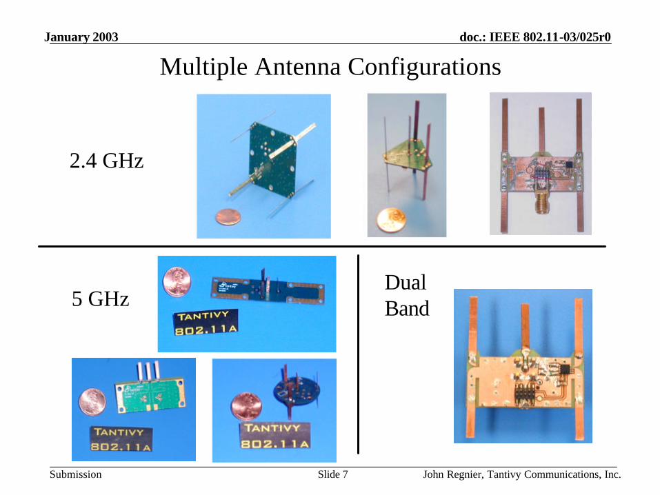
Multiple Antenna Configurations
5 GHz
2.4 GHz
DualBand

January 2003
John Regnier, Tantivy Communications, Inc.Slide 8
doc.: IEEE 802.11-03/025r0
Submission
• Gain– Omni mode: 0 dBi– Directional mode: 3.5 to 5 dBi
• Beam-width– 1 dB: 60°– 3 dB: 110°
• Front-to-back ratio: 13 dB• Interfaces
– RF: 50O– Control: 2 to 4 Digital signals– Power: 3 VDC, 200µA
Smart Antenna Description

January 2003
John Regnier, Tantivy Communications, Inc.Slide 9
doc.: IEEE 802.11-03/025r0
Submission
Representative Coverage Patterns
Directional PatternOmni Pattern
Omni & Directional Omni + 4 Directions
Directional pattern always has higher signal gain than Omni

January 2003
John Regnier, Tantivy Communications, Inc.Slide 10
doc.: IEEE 802.11-03/025r0
Submission
Smart Antenna Test Objectives
• Collect range-rate data with a 802.11b WLAN to investigate performance advantages with the use of Smart Antenna
• Investigate the impact of Smart Antennas for both downlink and uplink file transfers
• The goal of this testing is to demonstrate a data rate improvement with the Smart Antenna as compared to a switch diversity antenna

January 2003
John Regnier, Tantivy Communications, Inc.Slide 11
doc.: IEEE 802.11-03/025r0
Submission
Smart Antenna Test Equipment• Hardware
– Commercially available Access Point and Client / Station
• Software– WarFTPd 1.70.b01.04 (Aug 18 1998) application on the
laptop connected to the AP– DOS ftp command imbedded in batch files on the laptop
connected to the Client
• Antennas– AP: Internal diversity or External Smart Antenna– Client/Station: Internal diversity antenna

January 2003
John Regnier, Tantivy Communications, Inc.Slide 12
doc.: IEEE 802.11-03/025r0
Submission
Test SetupAccess Point
• Server - IBM ThinkPad• War FTPd software• Internal Switched Diversity Antenna• External Smart Antenna
Client/Station• Laptop - IBM ThinkPad• DOS FTP commands• Internal Switched Diversity Antenna

January 2003
John Regnier, Tantivy Communications, Inc.Slide 13
doc.: IEEE 802.11-03/025r0
Submission
Test Antenna• Photo and coverage patterns of test
antenna• Antenna provides eight directional
beams in 45º increments

January 2003
John Regnier, Tantivy Communications, Inc.Slide 14
doc.: IEEE 802.11-03/025r0
Submission
Smart Antenna Test Procedure
• File transfer size: 3 MB• Antenna Configurations
– Internal Switched Diversity– Smart Antenna in Omni mode– Smart Antenna at each of 4 angles (90° steps)
• Locate Client/Station at the desired test location• For each antenna configuration, transfer 5 files in
the desired direction using a DOS ftp command from Client/Station

January 2003
John Regnier, Tantivy Communications, Inc.Slide 15
doc.: IEEE 802.11-03/025r0
Submission
Smart Antenna Test Locations
Test Point TP# 6 7 8 9 10 28 29 11 12 13 14 15 16 18 19 20 21 22 23 24
Dist Tot (ft) 37 47 35 52 54 74 75 83 80 92 97 103 114 141 124 142 160 162 172 188
First Floor: Tantivy Corporate Headquarters
C . O . P .
FAX/COPY
REF
103MENSEC
104WOMENS105 EXIST STAIR
# 2
ELEC RM133
SERVER ROOM
C . O . P .
TX01
TP06 TP07 TP09
TP08
TP10TP28 TP12
TP13
TP11
TP15
TP29TP14
TP16
TP18
TP20TP19
TP21
TP23
TP24
TP22
Test Location
Access Point Location
LEGEND

January 2003
John Regnier, Tantivy Communications, Inc.Slide 16
doc.: IEEE 802.11-03/025r0
Submission
• Commercial Office Space• Exterior walls: Concrete block • Interior walls: Steel Studs with sheet rock• Ceiling height: 9 feet• Ceiling type: Suspended acoustic tiles• Data Collection: Daytime work hours
Smart Antenna Test Environment

January 2003
John Regnier, Tantivy Communications, Inc.Slide 17
doc.: IEEE 802.11-03/025r0
Submission
Smart Antenna Test: Data Analysis• Average the 5 file transfers
– Uplink and Downlink– Internal Switched Diversity Antenna– External Smart Antenna: Omni mode– External Smart Antenna: 4 directional positions
• Plots– Average Data for Uplink and Downlink
• Switched Diversity Antenna• Smart Antenna
– Min/Max/Avg Plot for Uplink and Downlink• Switched Diversity Antenna• Smart Antenna

January 2003
John Regnier, Tantivy Communications, Inc.Slide 18
doc.: IEEE 802.11-03/025r0
Submission
Smart Antenna Test Results - Downlink

January 2003
John Regnier, Tantivy Communications, Inc.Slide 19
doc.: IEEE 802.11-03/025r0
Submission
Smart Antenna Test Results - Uplink

January 2003
John Regnier, Tantivy Communications, Inc.Slide 20
doc.: IEEE 802.11-03/025r0
Submission
Smart Antenna: Downlink Min/Max/Avg

January 2003
John Regnier, Tantivy Communications, Inc.Slide 21
doc.: IEEE 802.11-03/025r0
Submission
Smart Antenna: Uplink Min/Max/Avg

January 2003
John Regnier, Tantivy Communications, Inc.Slide 22
doc.: IEEE 802.11-03/025r0
Submission
Smart Antenna Benefits Network Capacity
802.11bSmart Antenna
802.11bSwitched Diversity

January 2003
John Regnier, Tantivy Communications, Inc.Slide 23
doc.: IEEE 802.11-03/025r0
Submission
Average Network Throughput Comparison
0
0.5
1
1.5
2
2.5
3
3.5
11b Switched Diversity 11b Smart Antenna
Net
wo
rk T
hro
ug
htp
ut
Average Network Throughput

January 2003
John Regnier, Tantivy Communications, Inc.Slide 24
doc.: IEEE 802.11-03/025r0
Submission
The Smart Antenna improved WLAN performance• 82% increase in coverage (3.8dB to 5dB)• Benefits similar for Uplink and Downlink directions• Significant reduction in Min/Max difference results in
reduced variance• Performance improvements expected from interference
reduction• Test results were collected using existing technology,
not simulations
Summary