Web buckling tests on welded plate girders. Part 4: tests on plate
U. S. Department of Commerce
National Bureau of StandardsResearch Paper RP1934
Volume 41, November 1948
Part of the Journal of Research of the National Bureau of Standards
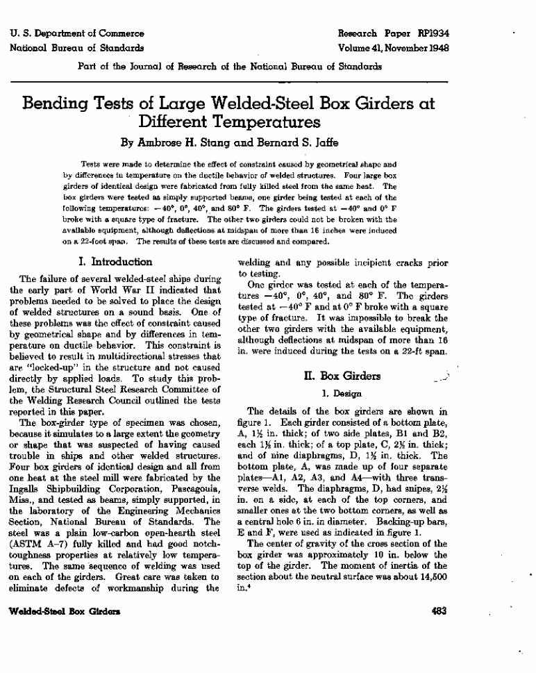
Bending Tests of Large Welded-Steel Box Girders atDifferent Temperatures
By Ambrose H. Stang and Bernard S. Jaffe
Tests were made to determine the effect of constraint caused by geometrical shape andby differences in temperature on the ductile behavior of welded structures. Four large boxgirders of identical design were fabricated from fully killed steel from the same heat. Thebox girders were tested as simply supported beams, one girder being tested at each of thefollowing temperatures: —40°, 0°, 40°, and 80° F. The girders tested at —40° and 0° Fbroke with a square type of fracture. The other two girders could not be broken with theavailable equipment, although deflections at midspan of more than 16 inches were inducedon a 22-foot span. The results of these tests are discussed and compared.
L IntroductionThe failure of several welded-steel ships during
the early part of World War II indicated thatproblems needed to be solved to place the designof welded structures on a sound basis. One ofthese problems was the effect of constraint causedby geometrical shape and by differences in tem-perature on ductile behavior. This constraint isbelieved to result in multidirectional stresses thatare "locked-up" in the structure and not causeddirectly by applied loads. To study this prob-lem, the Structural Steel Research Committee ofthe Welding Research Council outlined the testsreported in this paper.
The box-girder type of specimen was chosen,because it simulates to a large extent the geometryor shape that was suspected of having causedtrouble in ships and other welded structures.Four box girders of identical design and all fromone heat at the steel mill were fabricated by theIngalls Shipbuilding Corporation, Pascagoula,Miss., and tested as beams, simply supported, inthe laboratory of the Engineering MechanicsSection, National Bureau of Standards. Thesteel was a plain low-carbon open-hearth steel(ASTM A-7) fully killed and had good notch-toughness properties at relatively low tempera-tures. The same sequence of welding was usedon each of the girders. Great care was taken toeliminate defects of workmanship during the
welding and any possible incipient cracks priorto testing.
One girder was tested at each of the tempera-tures -40° , 0°, 40°, and 80° F. The girderstested at —40° F and at 0° F broke with a squaretype of fracture. It was impossible to break theother two girders with the available equipment,although deflections at midspan of more than 16in. were induced during the tests on a 22-ft span.
II. Box Girders >
1. Design
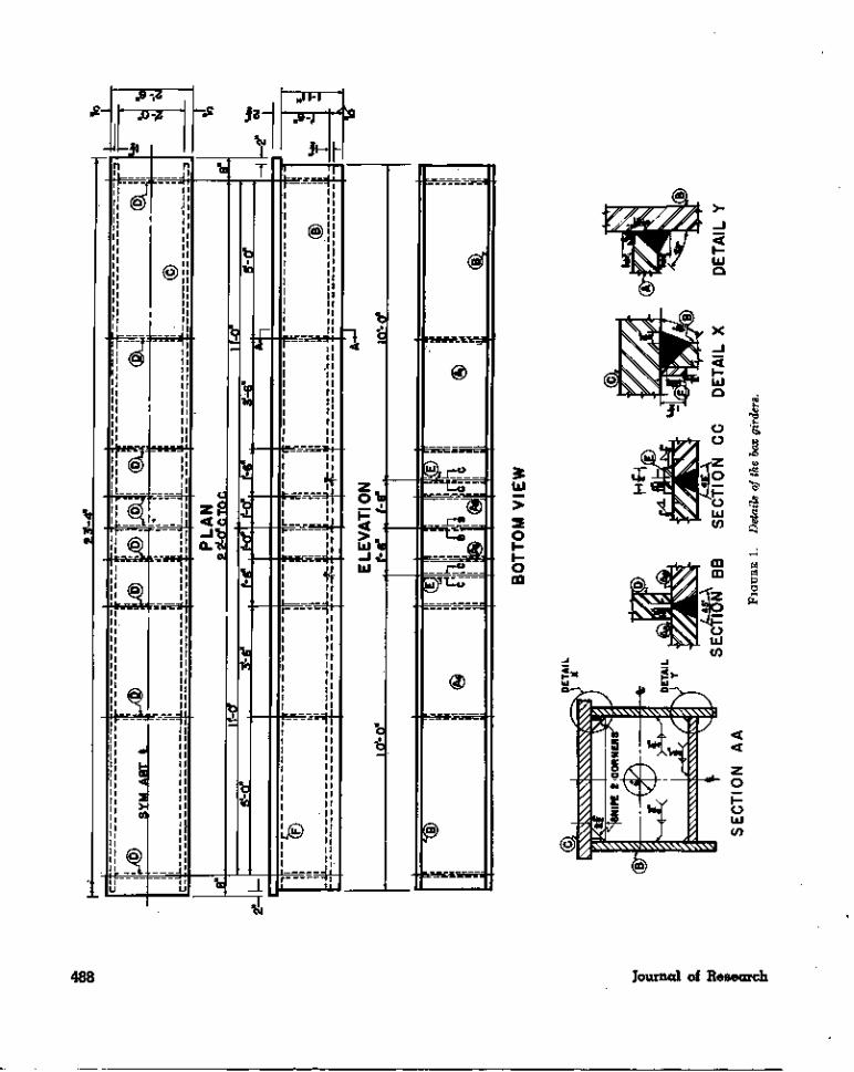
The details of the box girders are shown infigure 1. Each girder consisted of a bottom plate,A, iy2 in. thick; of two side plates, Bl and B2,each 1% in. thick; of a top plate, C, 2% in. thick;and of nine diaphragms, D, 1% in. thick. Thebottom plate, A, was made up of four separateplates—Al, A2, A3, and A4—with three trans-verse welds. The diaphragms, D, had snipes, 2%in. on a side, at each of the top corners, andsmaller ones at the two bottom corners, as well asa central hole 6 in. in diameter. Backing-up bars,E and F, were used as indicated in figure 1.
The center of gravity of the cross section of thebox girder was approximately 10 in. below thetop of the girder. The moment of inertia of thesection about the neutral surface was about 14,500in.4
Welded-Steel Box Girders 483

2. Fabrication
The sequence of assembling and welding of theparts of the girder was the same for each of thegirders and was as follows:
Plates Al, A2, A3, A4, Bl, B2, and D wereassembled, fitted, and tack-welded securely bywelding one pass on the diaphragm plates, D, tothe A and B plates. The outside welds of thetwo longitudinal butt joints joining the A to theB plates were made; the center diaphragm waswelded and welding of the other diaphragms pro-gressed to the ends. The back-up bars, E, wereinstalled on top of the A plates for the later trans-verse welds between the Al and A2 plates andbetween the A3 and A4 plates. The inside weldsof the two longitudinal butt joints between theA and B plates were completed, and the snipes atthe bottom of the diaphragms were welded. Theback-up bars, F, were installed for the longitudi-nal butt joints between the B and C plates, andthe strain gages were installed on the inside of thegirder. The C plate was fitted to the B plates,and the longitudinal butt joints between themwere made. The transverse butt joints betweenthe Al and A2, the A3 and A4, and the A2 andA3 plates were made, in that order, to completethe fabrication. The tops of the diaphragms, D,were not welded to the bottom of the C platebut formed a smooth bearing surface for plate C.
If cracks in the weld metal were revealed at anytime by magnafluxing, the metal around the crackwas chipped out and rewelded before the subse-quent welding pass was made.
The welding sequence, as described above, wasdesigned to set up large shrinkage stresses andproduce high values of locked-up stresses.
III. Coupons
Extra lengths of the steel plates, A, Bl, and B2,were furnished with each girder. Chemical anal-ysis of this material showed percentage contentsas follows: Carbon, 0.22; manganese, 0.56; phos-phorus, 0.015; and sulfur, 0.026.
From each of these lengths two tensile coupons,in the direction of rolling, were machined, six foreach girder. The coupons were 12 in. long, 1% in.in diameter in a reduced section 9 in. long, andwere threaded at both ends to fit the adaptorsof the pulling rods.
The tensile tests were made in a horizontal
Amsler testing machine, 100-kip capacity, at thesame temperature as that at which the correspond-ing box girder was tested. For those couponstested at temperatures below 80° F, the tempera-ture was maintained by carbon dioxide ice in aninsulated box surrounding the specimen. Fortemperatures of — 40° F and of 0° F, the tempera-ture was measured by means of two copper-con-stantan thermocouples attached one to each endof the reduced section of the specimen. A mer-cury thermometer was used for measuring thetemperature for tests at 40° and at 80° F.
The average results of the coupon tests are givenin table 1.
TABLE 1. Average results of tensile tests of coupons
Coupon length parallel to direction of rolling. Each value is the average forthe 6 coupons tested at the same temperature
Tem-pera-ture
°F-40
0+40+80
Young'smodulus
Kips/in.''29,39030,01030,18028, 580
Pois-son'sratio
(elastic)
0.273
.295
.270
Propor-tionallimit(offset
3X10⁻⁵)
Yield Tensilestrength strength
KipsI in.'28.325.822.421.3
Kips I in.*« 33. 9« 32.8b31.4b30.2
Kips! in.'68.770.167.765.6
Elonga-tion in
4 in.
Percent39.934.936.637.4
Reduc-tion ofarea
t Pe\rcent56.153.455.753.2
a Yield point by drop-of-beam method.t» Yield strength, 0.002-offset method.
The axial strains and the transverse strains wereeach determined by means of two SR-4 bondedresistance wire strain gages (A5 or A3) attachedat midlength of the specimen. Young's modulusof elasticity and Poisson's ratio in the elasticrange, and axial strain-stress and axial strain —Poisson's ratio data for plastic strains—were com-puted from these data. The remainder of theresults given in table 1 were computed in the con-ventional manner.
The values in table 1 show that the proportionallimit and yield-strength values decreased as thetemperature increased. The other values did notappear to be influenced by the temperature.
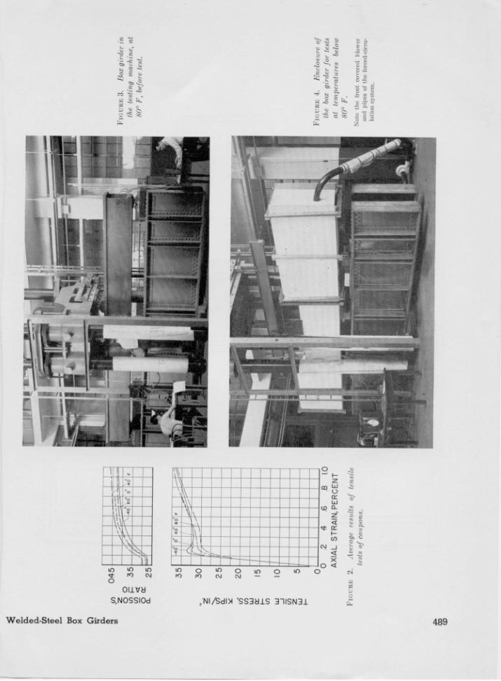
Figure 2 shows the average values for the stress-strain and Poisson's ratio-axial-strain relations.The latter values did not appear to vary consist-ently with temperature. In the stress-strain dia-gram, the stresses at the knee of the curves de-creased as the temperature increased, but on thelater ascending portions of the curves, the tem-perature effects appear to be negligible.
484 Journal of Research
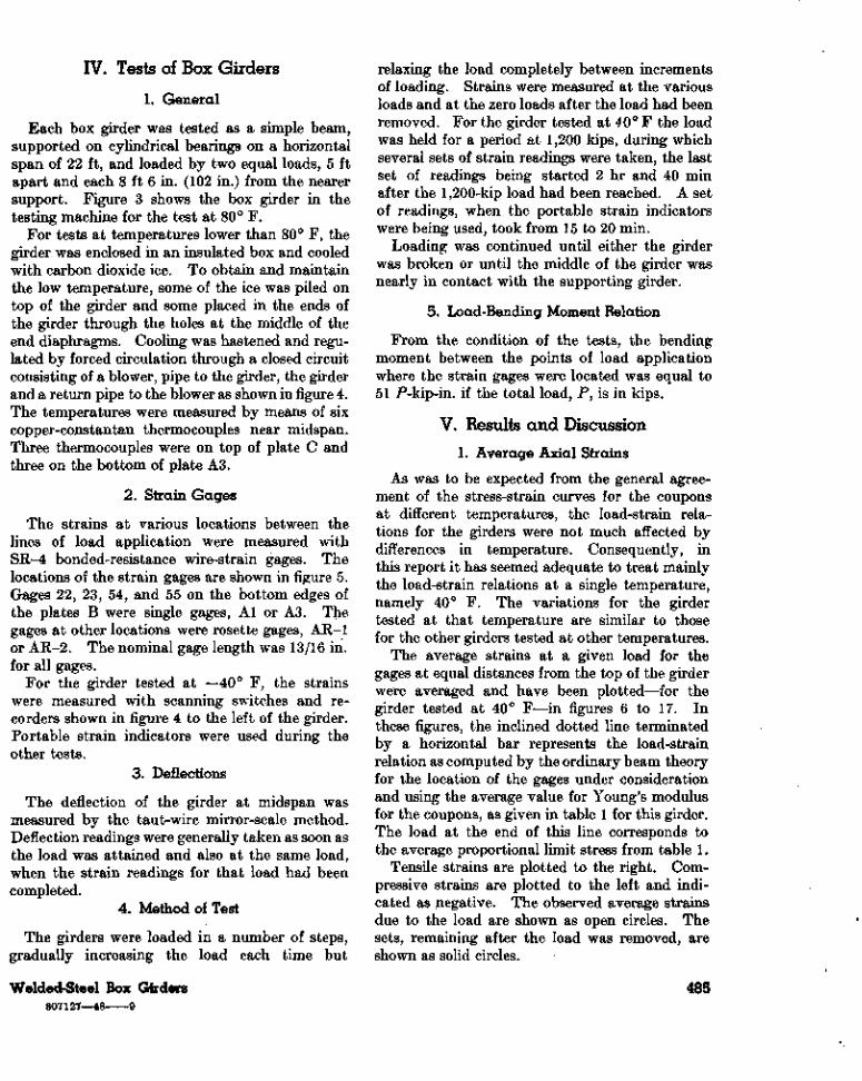
IV. Tests of Box Girders
1. General
Each box girder was tested as a simple beam,supported on cylindrical bearings on a horizontalspan of 22 ft, and loaded by two equal loads, 5 ftapart and each 8 ft 6 in. (102 in.) from the nearersupport. Figure 3 shows the box girder in thetesting machine for the test at 80° F.
For tests at temperatures lower than 80° F, thegirder was enclosed in an insulated box and cooledwith carbon dioxide ice. To obtain and maintainthe low temperature, some of the ice was piled ontop of the girder and some placed in the ends ofthe girder through the holes at the middle of theend diaphragms. Cooling was hastened and regu-lated by forced circulation through a closed circuitconsisting of a blower, pipe to the girder, the girderand a return pipe to the blower as shown in figure 4.The temperatures were measured by means of sixcopper-constantan thermocouples near midspan.Three thermocouples were on top of plate C andthree on the bottom of plate A3.
2. Strain Gages
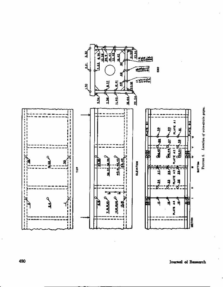
The strains at various locations between thelines of load application were measured withSR-4 bonded-resistance wire-strain gages. Thelocations of the strain gages are shown in figure 5.Gages 22, 23, 54, and 55 on the bottom edges ofthe plates B were single gages, Al or A3. Thegages at other locations were rosette gages, AR-1or AR-2. The nominal gage length was 13/16 in.for all gages.
For the girder tested at —40° F, the strainswere measured with scanning switches and re-corders shown in figure 4 to the left of the girder.Portable strain indicators were used during theother tests.
3. Deflections
The deflection of the girder at midspan wasmeasured by the taut-wire mirror-scale method.Deflection readings were generally taken as soon asthe load was attained and also at the same load,when the strain readings for that load had beencompleted.
4. Method of Test
The girders were loaded in a number of steps/gradually increasing the load each time but
relaxing the load completely between incrementsof loading. Strains were measured at the variousloads and at the zero loads after the load had beenremoved. For the girder tested at 40° F the loadwas held for a period at 1,200 kips, during whichseveral sets of strain readings were taken, the lastset of readings being started 2 hr and 40 minafter the 1,200-kip load had been reached. A setof readings, when the portable strain indicatorswere being used, took from 15 to 20 min.
Loading was continued until either the girderwas broken or until the middle of the girder wasnearly in contact with the supporting girder.
5. Load-Bending Moment Relation
From the condition of the tests, the bendingmoment between the points of load applicationwhere the strain gages were located was equal to51 P-kip-in. if the total load, P, is in kips.
V. Results and Discussion
1. Average Axial Strains
As was to be expected from the general agree-ment of the stress-strain curves for the couponsat different temperatures, the load-strain rela-tions for the girders were not much affected bydifferences in temperature. Consequently, inthis report it has seemed adequate to treat mainlythe load-strain relations at a single temperature,namely 40° F. The variations for the girdertested at that temperature are similar to thosefor the other girders tested at other temperatures.
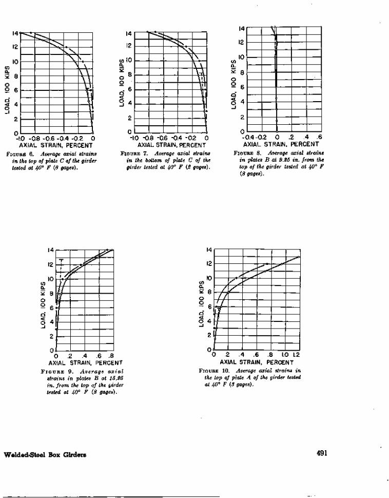
The average strains at a given load for thegages at equal distances from the top of the girderwere averaged and have been plotted—for thegirder tested at 40° F—in figures 6 to 17. Inthese figures, the inclined dotted line terminatedby a horizontal bar represents the load-strainrelation as computed by the ordinary beam theoryfor the location of the gages under considerationand using the average value for Young's modulusfor the coupons, as given in table 1 for this girder.The load at the end of this line corresponds tothe average proportional limit stress from table 1.
Tensile strains are plotted to the right. Com-pressive strains are plotted to the left and indi-cated as negative. The observed average strainsdue to the load are shown as open circles. Thesets, remaining after the load was removed, areshown as solid circles.
Welded-Steel Box Girders807127—48 9
485
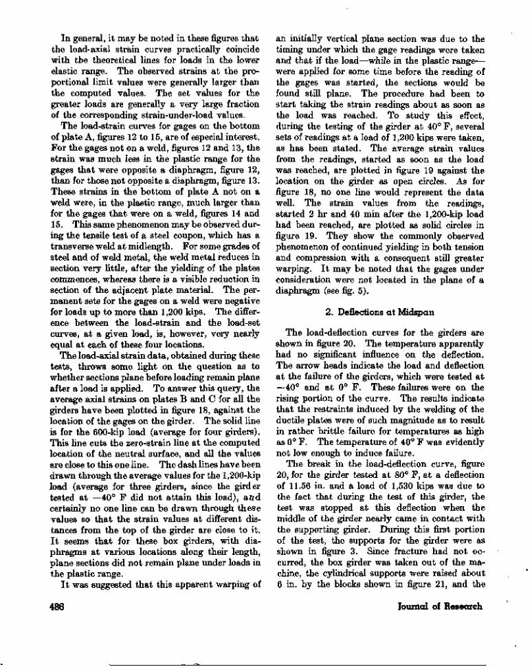
In general, it may be noted in these figures thatthe load-axial strain curves practically coincidewith the theoretical lines for loads in the lowerelastic range. The observed strains at the pro-portional limit values were generally larger thanthe computed values. The set values for thegreater loads are generally a very large fractionof the corresponding strain-under-load values.
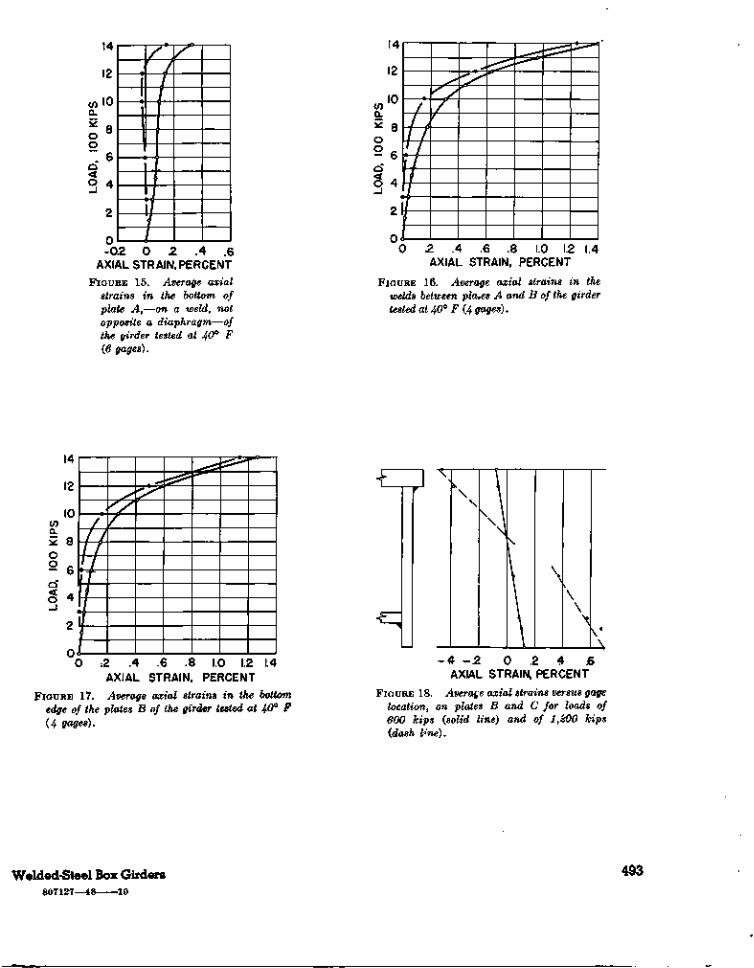
The load-strain curves for gages on the bottomof plate A, figures 12 to 15, are of especial interest.For the gages not on a weld, figures 12 and 13, thestrain was much less in the plastic range for thegages that were opposite a diaphragm, figure 12,than for those not opposite a diaphragm, figure 13.These strains in the bottom of plate A not on aweld were, in the plastic range, much larger thanfor the gages that were on a weld, figures 14 and15. This same phenomenon may be observed dur-ing the tensile test of a steel coupon, which has atransverse weld at midlength. For some grades ofsteel and of weld metal, the weld metal reduces insection very little, after the yielding of the platescommences, whereas there is a visible reduction insection of the adjacent plate material. The per-manent sets for the gages on a weld were negativefor loads up to more than 1,200 kips. The differ-ence between the load-strain and the load-setcurves, at a given load, is, however, very nearlyequal at each of these four locations.
The load-axial strain data, obtained during thesetests, throws some light on the question as towhether sections plane before loading remain planeafter a load is applied. To answer this query, theaverage axial strains on plates B and C for all thegirders have been plotted in figure 18, against thelocation of the gages on the girder. The solid lineis for the 600-kip load (average for four girders).This line cuts the zero-strain line at the computedlocation of the neutral surface, and all the valuesare close to this one line. The dash lines have beendrawn through the average values for the 1,200-kipload (average for three girders, since the girdertested at —40° F did not attain this load), a-Qdcertainly no one line can be drawn through thesevalues so that the strain values at different dis-tances from the top of the girder are close to it.It seems that for these box girders, with dia-phragms at various locations along their length,plane sections did not remain plane under loads inthe plastic range.
It was suggested that this apparent warping of
an initially vertical plane section was due to thetiming under which the gage readings were takenand that if the load—while in the plastic range—were applied for some time before the reading ofthe gages was started, the sections would befound still plane. The procedure had been tostart taking the strain readings about as soon asthe load was reached. To study this effect,during the testing of the girder at 40° F, severalsets of readings at a load of 1,200 kips were taken,as has been stated. The average strain valuesfrom the readings, started as soon as the loadwas reached, are plotted in figure 19 against thelocation on the girder as open circles. As forfigure 18, no one line would represent the datawell. The strain values from the readings,started 2 hr and 40 min after the 1,200-kip loadhad been reached, are plotted as solid circles infigure 19. They show the commonly observedphenomenon of continued yielding in both tensionand compression with a consequent still greaterwarping. It may be noted that the gages underconsideration were not located in the plane of adiaphragm (see fig. 5).
2. Deflections at Midspan
The load-deflection curves for the girders areshown in figure 20. The temperature apparentlyhad no significant influence on the deflection.The arrow heads indicate the load and deflectionat the failure of the girders, which were tested at—40° and at 0° F. These failures were on therising portion of the curve. The results indicatethat the restraints induced by the welding of theductile plates were of such magnitude as to resultin rather brittle failure for temperatures as highas 0° F. The temperature of 40° F was evidentfynot low enough to induce failure.
The break in the load-deflection curve, figure20, for the girder tested at 80° F, at a deflectionof 11.56 in. and a load of 1,530 kips was due tothe fact that during the test of this girder, thetest was stopped at this deflection when themiddle of the girder nearly came in contact withthe supporting girder. During this first portionof the test, the supports for the girder were asshown in figure 3. Since fracture had not oc-curred, the box girder was taken out of the ma-chine, the cylindrical supports were raised about6 in. by the blocks shown in figure 21, and the
486 Journal of Research
girder was again placed in the testing machine.The second portion of the test was made 7 daysafter the first portion of the test. On reloading,the load-deflection curve between loads of 1,530and 1,650 kips was not a smooth continuation ofthe load-deflection curve obtained during thefirst portion of the test but was much steeper.After the load of 1,650 kips had been attained,the deflection increased with little increase inload until the curve became practically a con-tinuation of that obtained during the first por-tion of the test. The moving of the girder andthe time between the two portions of the testevidently contributed to bringing about somechange in the load-deflection relation for thisgilder, which had already been subjected toplastic yielding.
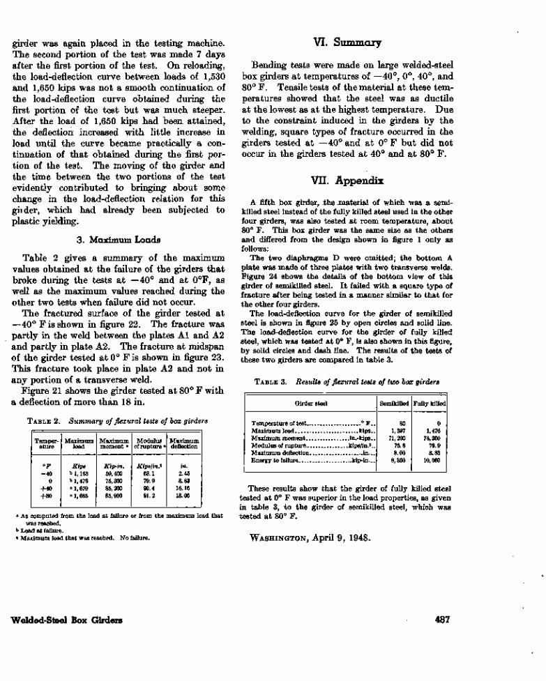
3. Maximum Loads
Table 2 gives a summary of the maximumvalues obtained at the failure of the girders thatbroke during the tests at —40° and at 0°F, aswell as the maximum values reached during theother two tests when failure did not occur.
The fractured surface of the girder tested at—40° F is shown in figure 22. The fracture waspartly in the weld between the plates Al and A2and partly in plate A2. The fracture at midspanof the girder tested at 0° F is shown in figure 23.This fracture took place in plate A2 and not inany portion of a transverse weld.
Figure 21 shows the girder tested at 80° F witha deflection of more than 18 in.
TABLE 2. Summary of flexural tests of box girders
Temper-ature
°F-40
0+40+80
Maximumload
Kipsb 1,165b 1,476° 1,670c 1,685
Maximummoment a
Kip-in.59,40075,30085,20085,900
Modulusof rupture »
Kips/in*63.179.990.491.2
Maximumdeflection
in.2.458.83
16.1618.06
VI, Summary
Bending tests were made on large welded-steelbox girders at temperatures of — 40°, 0°, 40°, and80° F. Tensile tests of the material at these tem-peratures showed that the steel was as ductileat the lowest as at the highest temperature. Dueto the constraint induced in the girders by thewelding, square types of fracture occurred in thegirders tested at —40° and at 0°F but did notoccur in the girders tested at 40° and at 80° F.
VII. Appendix
A fifth box girder, the material of which was a semi-killed steel instead of the fully killed steel used in the otherfour girders, was also tested at room temperature, about80° F. This box girder was the same size as the othersand differed from the design shown in figure 1 only asfollows:
The two diaphragms D were omitted; the bottom Aplate was made of three plates with two transverse welds.Figure 24 shows the details of the bottom view of thisgirder of semikilled steel. It failed with a square type offracture after being tested in a manner similar to that forthe other four girders.
The load-deflection curve for the girder of semikilledsteel is shown in figure 25 by open circles and solid line.The load-deflection curve for the girder of fully killedsteel, which was tested at 0° F, is also shown in this figure,by solid circles and dash line. The results of the tests ofthese two girders are compared in table 3.
TABLE 3. Results of flexural tests of two box girders
Girder steel
Temperature of test ° F__Maximum load _ ___ __kips._Maximum moment in.-kips__Modulus of rupture kips/in.2_.Maximum deflection in..Energy to failure. kip-in...
Semikilled
801,397
71,20075.68.00
8,350
Fully killed
01,476
75,30079.98.83
10,060
» As computed from the load at failure or from the maximum load thatwas reached.
Load at failure.o Maximum load that was reached. No failure.
These results show that the girder of fully killed steeltested at 0° F was superior in the load properties, as givenin table 3, to the girder of semikilled steel, which wastested at 80° F.
WASHINGTON, April 9, 1948.
Welded-Steel Box Girders 487
5:UJ
O03
488 Journal of Research
w o X aco
0
45
co |
- 3
5CO
<
-40°
80°
^= 0°
40°
F
<J7
Q.
CO CO UJ cr 1- co _) CO •z.
UJ
-40
I
//
0°4
0S
O /
F35 30 25 20 15 10 5 0
0 .2
4
.6
.8
1.0A
XIA
L S
TRA
IN, P
ER
CE
NT
FIG
UR
E 2.
A
vera
ge
resu
lts
of t
ensi
lete
sts
of c
oupo
ns.
FIG
UR
E 3.
B
ox g
ird
er i
nth
e te
stin
g m
achi
ne,
at80
° F
, be
fore
test
.
CO
FIG
UR
E 4.
E
ncl
osu
re o
fth
e bo
x gi
rder
for
test
sat
te
mpe
ratu
res
belo
w80
° F
.
Not
e th
e fr
ost
cove
red
blow
eran
d pi
pes
of t
he f
orce
d-ci
rcu-
lati
on s
yste
m.
I— •
I
fc \
s
Ui
&\ ° l *" -I
J 3 S
H 5] < 2)
TTITs!
O o
490 Journal of Research
14?
12
10
2 8o2 6
\\
VI\ I\1\li\
-1.0 -0.8 -0.6 -0.4 -0.2 0AXIAL STRAIN, PERCENT
FIGURE 6. Average axial strainsin the top of plate C of the girdertested at 40° F (6 gages).
14
12
,10
! 8i
. 6i
; 4
NV> \
\ \
vlMl
Xji
i1-1.0 -0.8 -0.6 -0.4 -0.2 0
AXIAL STRAIN, PERCENTFIGURE 7. Average axial strains
in the bottom of plate C of thegirder tested at 40° F {2 gages).
oo
\
0-0.4-0.2 0 .2 .4 .6AXIAL STRAIN, PERCENT
FIGURE 8. Average axial strainsin plates B at 9.25 in. from thetop of the girder tested at 40° F(8 gages).
14
12
10COQ_
* 8o— 6Q
0 .2 .4 .6 .8AXIAL STRAIN, PERCENT
F I G U R E 9. Average axial
strains in plates B at 15.25in. from the top of the girdertested at 40° F (8 gages).
Ti
11ft A
Ifi-i—j1
0 .2 .4 .6 .8 1.0 1.2AXIAL STRAIN, PERCENT
FIGURE 10. Average axial strains inthe top of plate A of the girder testedat 40° F (
Welded-Steel Box Girders 491

14
12
10COQ.
5 8oo 6Q< AO *
2
nl
//
/ j1 /iflT//
/
.—^
0 .2 .4 .6 .8 1.0 1.2 1.4 1.6AXIAL STRAIN, PERCENT
FIGURE 11. Average axial strains in platesB opposite the midheiyht of plate A of thegirder tested at 40° F (4 gages).
14
12
10
/ 4\
J1J
/^*
COQ_
oo 6Q< A,
_J .J
0 .2 .4 .6 .8 1.0 1.2AXIAL STRAIN, PERCENT
FIGURE 12. Average axial strains inthe bottom of plate A,—not on a weld,opposite a diaphragm—of the girdertested at 40° F (6 gages).
§ 4
2^
/
//
/ , /
1//
/<
0 .2 .4 .6 .8 1.0 1.2 1.4 1.6 1.8 2.0AXIAL STRAIN, PERCENT
FIGURE 13. Average axial strains in the bottom of plate A,—not on a weld, not opposite a diaphragm—of the girdertested at 40° F (3 gages).
1I1zt.
ZJ1
—I_/,
LZ//
2 6
-0.2 0 .2 .4AXIAL STRAIN, PERCENTFIGURE 14. Average axial
strains in the bottom ofplate A,—on a weld, op-posite a diaphragm—ofthe girder tested at 40° F{8 gages).
492 lournal of Research
14
12
0)10a.
oo
_7ZLJZ±j
±1Ji///
-0.2 0 .2 .4 .6AXIAL STRAIN, PERCENT
FIGURE 15. Average axialstrains in the bottom ofplate A,—on a weld, notopposite a diaphragm—ofthe girder tested at 40° F(6 gages).
o
Q
/
f/
///
1
/f
0 .2 .4 .6 .8 1.0 1.2 1.4AXIAL STRAIN, PERCENT
FIGURE 16. Average axial strains in thewelds between places A and B of the girdertested at 40° F (4 gages).
if)a.
O
OA
D,
14
12
10
8
6
4
2
Or
/
/ /
/ // /
/
/ -f -f
>̂/̂
0 ;2 .4 .6 .8 1.0 1.2 1.4AXIAL STRAIN, PERCENT
FIGURE 17. Average axial strains in the bottomedge of the plates B of the girder tested at 40° F(4 gages).
\\
- 4 - .2 0 .2 4 .6AXIAL STRAIN, PERCENT
FIGURE 18. Average axial strains versus gagelocation, on plates B and C for loads of600 kips (solid line) and of lfiOO kips{dash tine).
Welded-Steel Box Girders 493
807127—48 -10

-.4 -.2 0 .2 .4 .6 .8AXIAL STRAIN, PERCENT
FICTJRE 19. Average axial strains versus gagelocation for a load of 1,200 kips on the girdertested at 40° F.
Open circles are for readings started as soon as the load wasreached; solid circles for readings started 2 hr 40 min after theload was reached.
16
14
1?
00
KIP
SCD
O
Q" 6
O
~* 4
2
0
/
L2^ • - 4 0 F
, - /
- 0
— -
4 0°
—'
80*
*
F
0 4 8 12 16DEFLECTION, IN.
FIGURE 20. Deflection at mid-span for the girders.
FIGURE 21. Girder tested at 80° F when the deflection was18.06 in.
22. Fractured surface of the girder tested at —40° F.
494 Journal of Research
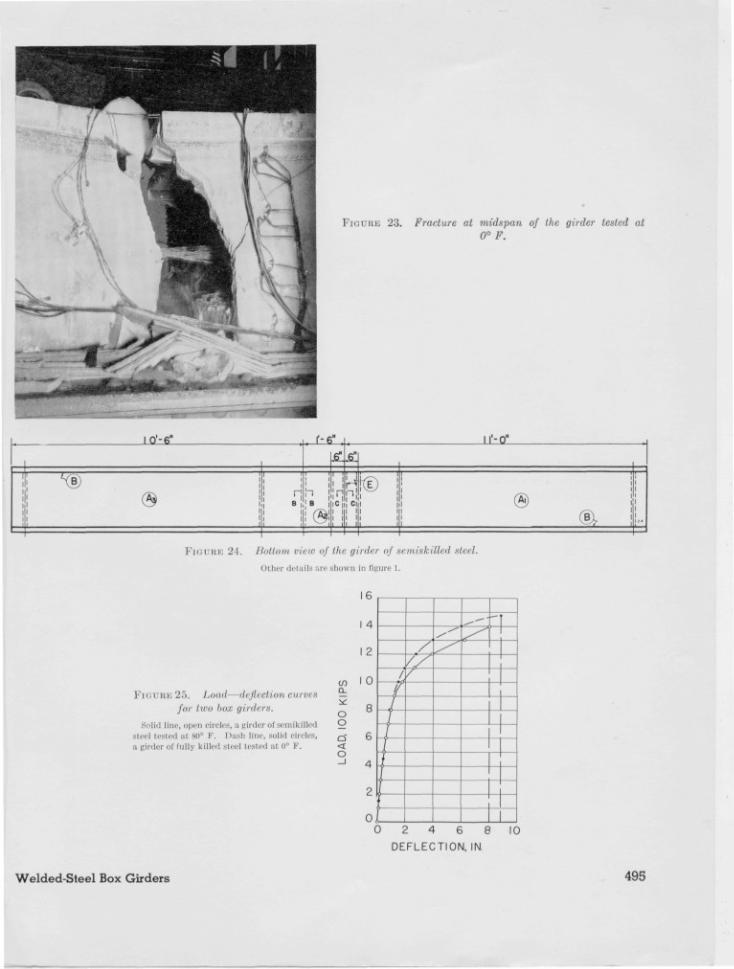
FIGURE 23. Fracture at midspan of the girder tested at
0° F.
I O'-6" f-6" Il'-O"
nnCl l ®
FIGURE 21. Bottom view of the girder of semi ski lied steel.
Other details are shown in figure i.
FIG CTBE 25. Loud— <lej! eel i<m curvesfor two box girders.
Solid line, open circles, a girder Of semikilledSteel (<'slcd at, H0° F. Dash line, solid circles,a girder or fully killed steel tested at o° F .
CL
oo
Q
O
16
I 4
I 2
I 0 I— f_I
~Y2_
f—
/'/
\
0 2 4 6 8
DEFLECTION, IN.
10
Welded-Steel Box Girders 495