
BENCHMARKING OF THE ACTUAL INJECTION OF THE PRODUCT VERSUS PLASTIC
24
BENCHMARKING OF THE ACTUAL INJECTION OF THE PRODUCT VERSUS PLASTIC SIMULATION SOFTWARE ZUL AMRI BIN A.BAKAR UNIVERSITI MALAYSIA PAHANG
Transcript of BENCHMARKING OF THE ACTUAL INJECTION OF THE PRODUCT VERSUS PLASTIC

BENCHMARKING OF THE ACTUAL INJECTION OF THE
PRODUCT VERSUS PLASTIC SIMULATION SOFTWARE
ZUL AMRI BIN A.BAKAR
UNIVERSITI MALAYSIA PAHANG

ii
SUPERVISOR’S DECLARATION
We hereby declare that we have checked this project and in our opinion this project is
satisfactory in terms of scope and quality for the award of the degree of Bachelor of
Mechanical Engineering with Manufacturing
Signature :
Name of Supervisor :
Position :
Date :
Signature :
Name of Panel :
Position :

iii
STUDENT’S DECLARATION
I hereby declare that the work in this thesis is my own except for quotations and
summaries which have been duly acknowledged. The thesis has not been accepted for
any degree and is not concurrently submitted for award of other degree.
Signature :
Name : ZUL AMRI BIN A.BAKAR
ID Number : ME05015
Date : 4 NOVEMBER 2008

iv
DEDICATION
“Dedicated to my family the mission of my life”

v
ACKNOWLEDGEMENTS
Gratefully expressed from deep of my heart and highly gratitude dedicated
toward my supervisor Mr. Zamzuri Hamedon for his precious guidance, invaluable ideas
and knowledge, constantly encourage and support during easy and hard time to make
this project available. Vast knowledge of him in multiple fields as well as technical and
science conduction always impressing me and the feeling will persist to stay with me
forever to be my model in achieving the future. I appreciate his consistent support from
the first day of meeting until this concluding moment. I am truly grateful for his
progressive vision about my training in science, his tolerances of my naive mistake, his
patience in guiding my understanding, and his commitment to my future career. I also
thankfully for the time spent for guiding me, transferring the knowledge and skills, and
correcting my many mistakes and problems.
My sincere thanks to staffs of Mechanical Lab, UMP especially Mr. Khairul
Azha in assisting, guiding and teaching me with his all dedications and sincere during all
my days working at the lab. I am grateful for his patience in explaining my mistakes and
misunderstanding which make this project available.
I am also indebted to my parents and family for their limitless love and supports
during the progress of this project and as well as my whole life. I also dedicated this
gratitude towards my colleagues for their ideas and support. Their encouragement and
sacrifices make many unforgettable memories, knowledge and experiences for me
during the years spent in UMP.

vi
ABSTRACT
The idea of this project, benchmarking of the actual injection of the product versus
plastics simulation software is to do analysis of the parameters that involved in the
plastic injection molding in order to determine the best solution to overcome the
problems and defects that occurred in the plastic injection molding. By actual injection
processes, the results that can be observed are limited such as temperature, stress and the
point of gate that are almost impossible to be analyzed by naked eye. Thus, for such
details information the engineer can depend on Computer Aided Engineer (CAE) or
Computer Aided Manufacturing (CAM) tools such as in this case Moldflow, in
generating the accurate data of the parameter that has been analyzed. The tools are
capable in assisting the designation of the mold and the parts that need to be produced
by generates the data that cannot be achieved by doing the actual experiments. Hence,
actual injection analysis needs quite a lot of effort to determine the optimal parameters
for the injection process by experienced expertise. Try and error method was traditional
way in injecting the part into fine product which consumed a lot of time and energy as
well as increase the production cost. The result between software simulation and the
actual injection might have slight differences because of several factors. The factors can
be determined by doing both analyses and comparing the result will generated the data
of error percentage of the simulation software to actual injection as same as factors of
the errors.

vii
ABSTRAK
Idea mengenai projek ini iaitu perbandingan antara injeksi sebenar produk dan perisian
simulasi plastik adalah untuk menganalisa faktor-faktor yang boleh diukur yang terlibat
secara langsung dalam arena acuan injeksi plastik. Ini adalah bertujuan untuk mencari
jalan penyelesaian terbaik untuk mengatasi masalah dan kecacatan yang terdapat pada
model injeksi plastik. Berdasarkan injeksi sebenar hasil analisis yang boleh diperhatikan
adalah terhad kepada beberapa permerhatian sahaja dan faktor seperti suhu, tekanan dan
titik kedudukan get adalah menghampiri mustahil untuk diperhatikan dengan
menggunakan deria penglihatan manusia. Oleh itu untuk maklumat terperinci seperti
perkara tersebut jurutera-jurutera boleh menggunakan perisian “Computer Aided
Engineer” (CAE) atau “Computer Aided Manufacturing” (CAM) seperti dalam kes ini
iaitu Moldflow untuk menghasilkan maklumat dan data yang tepat setelah menganalisa
permerhatian tersebut. Perisian tersebut berupaya untuk menbantu dalam mereka cipta
acuan dan model produk yang perlu dihasilkan dengan menghasilkan data yang tidak
dapat diperolehi dengan melakukan eksperimen injeksi sebenar. Eksperimen injeksi
sebenar memerlukan kepakaran dan tenaga yang tinggi untuk menghasilkan keadaan
terbaik bagi proses injeksi tersebut. Kaedah cuba jaya adalah kaedah tradisional yang
diguna pakai untuk menentukan keadaan terbaik tersebut namun ianya memerlukan
masa dan tenaga yang banyak di samping meningkatkan kos pembuatan. Nilai dan
keputusan yang dihasilkan oleh simulasi perisian dan injeksi sebenar berkemungkinan
mempunyai sedikit perbezaan yang disebabkan oleh beberapa faktor dan faktor-faktor
tersebut boleh dikenal pasti dengan melakukan kedua-dua analisa tersebut dan hasil
analisa tersebut dibandingkan. Perbandingan tersebut akan menghasilkan peratusan
kesilapan antara perisian simulasi dan injeksi sebenar.

viii
TABLE OF CONTENTS
Page
SUPERVISOR’S DECLARATION ii
STUDENT’S DECLARATION iii
DEDICATION iv
ACKNOWLEDGEMNT v
ABSTRACT vi
ABSTRAK vii
TABLE OF CONTENTS viii
LIST OF TABLES xi
LIST OF FIGURES xii
LIST OF ABREVIATIONS xiii
CHAPTER 1 INTRODUCTION
1.1 Introduction 1
1.2 Problem Statement 4
1.3 Project Objectives 4
1.4 Project Scopes 5
CHAPTER 2 LITERATURE REVIEW
2.1 Introduction 6
2.2 Injection Molding Machine 6
2.3 Important Components in Plastic Injection Molding Machine 8
2.4 Mold 8
2.5 Runner 9

ix
2.6 Defects on Plastic Injection Molding 11
2.7 Previous Research on Plastic Injection Molding Analysis 12
2.8 Materials of the Model 14
CHAPTER 3 METHODOLOGY
3.1 Introduction 17
3.2 Product Design 18
3.3 Simulation Software Analysis
21
3.4 Actual Injection Experiment 23
3.5 Benchmarking 24
3.6 Methodology Flowchart 25
CHAPTER 4 RESULT AND DISCUSSION
4.1 Software analysis results 27
4.2 Actual injection experiment results 31
4.3 Comparison between simulation software and actual injection 32
4.3.1 Comparison of parameters 324.3.2 Comparison of physical analysis result 35
4.4 Error percentage calculation 37
4.4.1 Dosage volume error percentage calculation 374.4.2 Injection pressure error percentage calculation 37
CHAPTER 5 CONCLUSION AND RECOMMENDATION
5.1 Conclusion 38
5.2 Recommendation 40
REFERENCES 41

x
APPENDICES
A Final Year Project Gantt Chart 42
B Final Year Project flow chart 43

xi
LIST OF TABLES
Table No. Page
2.1 Processing properties of ABS material 16
3.1 Dimension and properties of sprue, runner and gate 21
3.2 Dimension of the mold 21
4.1 Fill analysis result 28
4.2 Estimated sink mark 29
4.3 Estimated warpage 30
4.4 Actual injection analysis result 32
4.5 Comparison of results from actual injection and software simulation 33

xii
LIST OF FIGURES
Figure No. Page
2.1 Important part of injection molding machine 8
2.2 Conventional layout 10
2.3 Improved layout 10
2.4 Balanced H layout 11
2.5 Circular layout 11
3.1 3D view of paper rack model – Upper 19
3.2 3D views of paper rack model – Below 19
3.3 Upper view of paper rack model 20
3.4 Bottom view of paper rack model 20
3.5 Distorted area in round circle 20
3.6 Flowchart of software simulation operation 22
3.7 Mold of paper rack product 24
3.8 Methodology flowchart 26
4.1 Pie chart of cycle time 29
4.2 Sink mark 30
4.3 Warpage 31
4.4 Injected product by using software simulation result 34
4.5 Flashing defect 34
4.6 Air trap defect indicated by software in pink round shape 35
4.7 Weld line estimated by the colored line 36
4.8 Sink mark on both analyses 36

xiii
LIST OF ABBREVIATIONS
CAE Computer Aided Engineer
CAM Computer Aided Manufacturing
FEA Finite Element Analysis
MPA Moldflow Plastic Advisor
ABS Acrylonitrile-Butadiene-Styrene
MIMO Multiple-Input Multiple-Output
MPI Moldflow Plastic Insight

CHAPTER 1
INTRODUCTION
1.1 INTRODUCTION
Nowadays, plastic injection molding is become one of the important industry in
the world. This industry placed in the manufacturing field and most of the parts, objects
and goods surrounding are based on plastic material. Injection molding is one of the
manufacturing techniques from manufacturing engineering field in producing parts that
based on plastic material. The molten plastic that has been melted from the hopper
through the barrel will be injected at high pressure into a mold with the cavity of desired
parts shape. Major problem in plastic injection molding industry is the results are
somehow different from the simulation software. Thus, it will contribute serious
problems for the Quality Assistant and the engineer in order to predict the suitable
setting or design of the part and mold. This project will compare those results. The
parameters need to be selected as not all of the data or results can be observed by naked
eye by actual injection. Published software, Moldflow will be used during analysis by
simulation. In the end the results gained from those two approaches will be compared
and analyzed to observe if the results are same, acceptable or errors.

2
This analysis can be done in many approaches but based on this project’s title the
study has to be done by manual experimental and at the same time by plastic simulation
software. Benchmarking can be defined as comparison or to differentiate two or more
parameters that have been studied. From the title of this project, in other words, it means
to make comparison of the results, observations and consequences between the actual
manually handled plastic injection molding machine and the results that have been
analyzed by the plastic simulation software. There are some analysis can be compared
between the actual injection and software simulation. For an example is the common
defect occurred in plastic manufacturing industry which is shrinkage. Volumetric
shrinkage is the contraction of polymer due to the change in temperature from melt
temperature to ambient temperature [1]. High volumetric shrinkage can cause part
warpage, sink marks, critical dimensions that are too small and internal voids. Excessive
wall thickness and inadequate packing can both contribute to high volumetric shrinkage
in a part. The solutions to avoid this defect are altering the part design such as the wall
thickness and the other critical area. Second solution is altering the gate locations and
lastly altering the processing conditions by increase the packing pressure. There other
analysis that can be benchmark is the deflection of the finished products. The deflection
resulting from the Moldflow shows the deflection at each node of the part (warpage or
stress analysis), or each node of the wire or paddle (microchip encapsulation analysis),
based on a "best fit" technique, where the original geometry and the deformed geometry
are overlaid in such a way that they best fit together, or based on a defined anchor plane
defined. There are a number of possible variants of the deflection result according to:
• Analysis type - The result name may indicate the type of analysis that was run, that is,
either small deflection or large deflection. If this is not indicated in the result name,
then the results will apply to a small deflection analysis.
• Net vs component deflections - The net view of net deflections at each node, or the
component of the deflection either along the X, Y or Z axis. The axis directions are
determined by the defined anchor plane and are indicated in the anchor plane
symbols.

3
• All effects versus warpage contributors - There are four sets of deflection results. To
create these results, run a small deflection warpage analysis and select the Isolate
cause of warpage option on the Warp Settings page of the Process Settings Wizard.
There are also analyses that can not be compared between those two approaches
yet it is important to be analyzed such as for an example the fill time analysis. As in
Moldflow software the results of this analysis is called fill time result. The Fill time result
shows the position of the flow front at regular intervals as the cavity fills. Each color
contour represents the parts of the mold which were being filled at the same time. At the
start of injection, the result is dark blue, and the last places to fill are red. If the part is a
short shot, the section which did not fill has no color. Secondly, the analysis of time to
freeze also an important parameter yet can be observed by naked human eyes. Thus, from
Moldflow judgments the Time to freeze result is generated from a Midplane and Fusion
flow analysis, and shows the amount of time taken from the end of fill at 100% to the
ejection temperature. This result takes into account the dynamics of both filling and
packing phases, where new hot material enters the cavity. This new hot material affects
the cooling time.
Shrinkage is the amount by which a molded product is smaller than the size of
cavity space wherein it was produced by injecting plastic under high pressure injection
and at high temperature [2]. There are three rules regarding the shrinkage behavior which
the first rule is, there is a definite relationship between pressure (P), volume (V) and
temperature (T). This relationship is different for various plastic. Any and all conditions
that affect those parameters will affect the shrinkage. Second rule is when a volume of
plastic is heated it will expands. Then when it cools to the original temperature, it will
contract to the original volume. Third rule is when a plastic is compressed the volume
will be reduced. When the pressure is reduced to the original pressure it will return to its
original volume. The greater the temperature difference between the room temperature
and injected plastic then the shrinkage also will be greater. Timing also can affect the
shrinkage behavior where the longer the injection pressure is kept on the plastic in the
cavities the less will be shrinkage. In term of pressure, where the pressure on the plastic

4
(in cavity) is high, less shrinkage will take place but in the other hand when the area is
low in pressure the plastic will shrink more. It also can be affected by plastic material
characteristics. Each plastic has a typical coefficient of temperature expansion. In most
cases it is impossible to predict with certainty the correct shrinkage of a material since it
depends on so many factors.
1.2 PROBLEM STATEMENT
1. The differences of the result between the software and the machine are not 100%
the same
2. The detail about the defects that can not be analyzed by using simple observation
methods have to be determined by using software simulations
3. The condition of mold and software capabilities might influence the results of
both analyses.
1.3 PROJECT OBJECTIVES
a. To get the parameter value using the CAE or FEA software – by Moldflow
software
b. To use the data from Moldflow to setup plastic injection molding machines
c. Determine the differences of results of the parameters between actual
experiments and software simulation analysis

5
1.4 PROJECT SCOPES
a. Literature review will be done regarding to the title of this project
b. For this project Moldflow Plastic Advisor (MPA) software will be used for the
software analysis method.
c. Reversed engineering will be applied according to the already available mold to
obtain the parameters of the mold
d. The product designation is depends on the finished product and for this project
the product is paper rack.
e. The material type will be used is Acrylonitrile-butadiene-styrene (ABS).
f. The machine that will be used is Arburg 520C Allrounder 2000-800 for the
actual injection analysis.
g. The processing properties of the material will be used as reference for the
software analysis
h. The model of the product is design by using CAE software Solidwork
i. The machine will be setup by using results from the software for the actual
injection analysis.
j. The result from software analysis and the result from actual injection analysis
will be compared.

CHAPTER 2
LITERATURE REVIEW
2.1 INTRODUCTION
Parts that based on the plastic material can be produced in many ways and the
most popular approaches are by injection. The basic concept of this method is injecting
the molten plastic material into the mold with the cavity of the product’s shape and the
material will be cooled down then forming into solid form of the desired product’s shape
before it ejected by pin ejector and ready to be used. In injection molding process, there
are four main steps or cycles have to be taken namely filling cycle, cooling cycle, mold
open cycle and part ejects. The crucial step is during the filling cycle since the quality of
the goods and lifespan of the molds are depending seriously on this.
2.2 INJECTION MOLDING MACHINE
Basically, the injection molding machine functions as the holder of the mold and
injecting the molten material into the cavity inside of the mold. There are several types
of injection machine but most widely used are hydraulic type, all-electric and
combination of both types. Generally, an all electric type machine not very different
from hydraulic type in term of body mechanism [3]. However, there are also significant
differences between those two types of machine and the differences as stated below:
i. the uses of AC Servo Motor
ii. the uses of ball screw

7
iii. the uses of gear and timing belt
The existences of these components are to substitute original hydraulic element
such as hydraulic motor, directional valve, hydraulic board and cylinder. Since the
electric elements are used to drive the injection machine so it is therefore called “All-
Electric”. The advantages of this type of injection machine are no problem with oil
leakage as it does not use oil for hydraulic system thus will generate less pollution. It
also has less operation noise, less energy consumption and has high accuracy of mold
movement. In the other hand the operation cost of the machine is high with high cost of
servo motor. The durability of ball screw also needs to be put under consideration since
it has certain lifespan. This machine has slight difficulty on developing large tonnage
force model which can resulted instable power supply and also unable to use
accumulator to create transient high pressure. An injection molding machine is called
hydraulic type when it use hydraulic system to open or closed halves mold by a
reversible fluid motor actuated by a die control valve. The advantages of hydraulic type
machine are the mold is easier to be setup onto the machine, the clamp pressure can be
easily determined, low maintenance cost with low platen deflection since the force
concentrated at the center of the platen. Vice versa the disadvantages of this machine are
the oil for the hydraulic system tends to leakage and it requires large volume of
hydraulic oil. The energy consumption is inefficient and overcompensate is a must due
to compressibility of the oil. This machine also required large space.

8
2.3 IMPORTANT COMPONENT IN PLASTIC INJECTION MOLDING
MACHINE
Plastic injection molding machine consists of several components that assembled
into a whole machine.
Fig 2.1: Important part of injection molding machine
Source: Plastic Technology, BMF 4713 Teaching Handout (2008)
As referring to the diagram, there are two main unit in the injection molding
machines where they are stated as injection unit and clamping unit. In the clamping unit
is consisted by stationary platen, mold, moveable platen, tie rods, clamping cylinder and
in this case hydraulic cylinder since the machine is hydraulic type. The function of
clamping unit is to holds the mold together, open and closed the mold automatically, and
finish the injection process by ejects the finished product.
2.4 MOLD
Mold can be divided into two main types which are two-plate mold and three-
plate mold type. The main difference of these two types of the mold is about the function
of handling the runner. Three-plate mold has self-degating function which means the
runner is disassembled from the finished injected products by mean of mechanical

9
movements of the assembled mold. The three-plate mold has an extra plate compared to
the two-plate mold with present of stripper plate assembled between the fixed half mold
plate and top plate of sprue bushing. This function will produce two parting line instead
of a single parting line for the two-plate mold type where the extra parting line located at
the fixed half mold plate and stripper plate.
Three-plate mold is better when the quality of the surface finish on the products
is crucial matter since the runner and sprue part do not have to be cut manually by
manpower which the quality of the cutting will not be consistent with extra cost
consumed for the salary man. The detached sprue and runner will be treated as wastes
and depending on the material it can be recycle by crushing them back into particle or
pallet form. If the material used categorized in thermoset family it can not be recycled
since the chemical degradation of the material will be not resulting into a desired
finished product and can be harmful for the screw where it can burning inside the barrel.
2.5 RUNNER
Runner is channel into the mould plate to connect the sprue and gate to
impression. The type of runner can be defined as one of the most important factors that
should be considered before fabricating process and mainly there are two types of runner
namely cold runner and hot runner. They can be known by present of filament at the
runner where hot runner type is chosen for one mold. There are some significant criteria
differences of the two types of runner. The cold runner system has some disadvantages
such as high cost of energy and workmanship, high scrap ratio, low product quality of
surface appearances and requirement of high injection pressure. In the other way, hot
runner system is able to provide precisely adjustable process temperature, uniform
filling in multi-cavity molds, even heat distribution in the molds, improvement on
mechanical properties of the injected products, cuts in production cost and shorter mold
opening distance because absence of sprue while shorten the cycle time. The layout of
the runner system also needs to be considered as critical factor which it depend on the
shape of desired product and size. There are four main layouts such as conventional

10
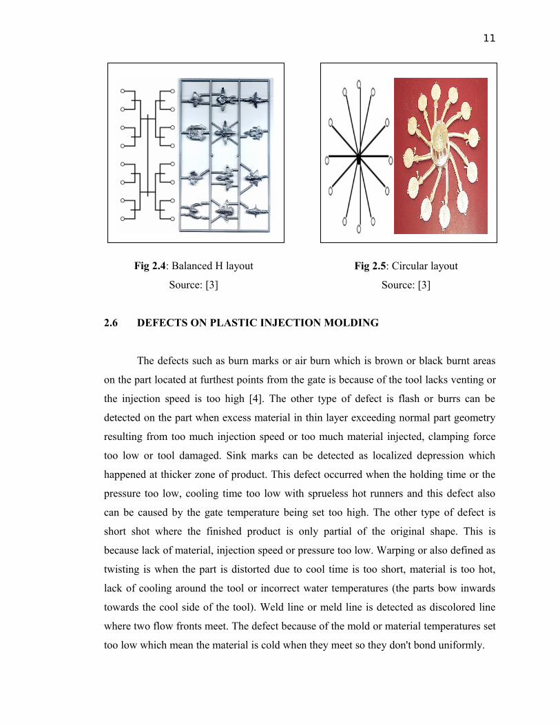
[Fig 2.2], improved [Fig 2.3], balanced H [Fig 2.4] and circular [Fig 2.5]. When
designing a mold the criteria of the mold is need to be categorized into consideration.
The runner should be providing maximum cross sectional area from the standpoint of
pressure transfer and a minimum contact area from the standpoint of heat transfer.
The following factors are should be considered while deciding the runner size.
The first factor is about the wall section and volume of the molding. The cross sectional
area of the runner must be sufficient to permit the molten material to pass through and
fill the impression before the runner freezes. The second factor is the distance between
impression and main runner or sprue where the resistance of flow is greatly depends on
the length of the runner. When the gap between the impression and sprue or main runner
is large it will make larger resistance for the flowing molten material. Thirdly is about
the runner cooling system where the large size of runner will increase the cooling time.
Fig 2.2: Conventional layout
Source: [3]
Fig 2.3: Improved layout
Source: [3]
11
Fig 2.4: Balanced H layout
Source: [3]
Fig 2.5: Circular layout
Source: [3]
2.6 DEFECTS ON PLASTIC INJECTION MOLDING
The defects such as burn marks or air burn which is brown or black burnt areas
on the part located at furthest points from the gate is because of the tool lacks venting or
the injection speed is too high [4]. The other type of defect is flash or burrs can be
detected on the part when excess material in thin layer exceeding normal part geometry
resulting from too much injection speed or too much material injected, clamping force
too low or tool damaged. Sink marks can be detected as localized depression which
happened at thicker zone of product. This defect occurred when the holding time or the
pressure too low, cooling time too low with sprueless hot runners and this defect also
can be caused by the gate temperature being set too high. The other type of defect is
short shot where the finished product is only partial of the original shape. This is
because lack of material, injection speed or pressure too low. Warping or also defined as
twisting is when the part is distorted due to cool time is too short, material is too hot,
lack of cooling around the tool or incorrect water temperatures (the parts bow inwards
towards the cool side of the tool). Weld line or meld line is detected as discolored line
where two flow fronts meet. The defect because of the mold or material temperatures set
too low which mean the material is cold when they meet so they don't bond uniformly.