Belongs to the future generation for technical advancement ... · Belongs to the future generation...
163
Belongs to the future generation for technical advancement; today PEDROLLO S.p.A. is a world reality, with a commercial network present in more than 140 countries. Founded in 1974 Pedrollo Spa is now a reference mark globally in the water supply sector. Covering an area of 60,000 square metres the Company utilises extremely high technology with a high level of automation which place the Company at the highest level in its field both for the level of investments as well as for the capability to control the quality throughout the entire production process.
Transcript of Belongs to the future generation for technical advancement ... · Belongs to the future generation...

Belongs to the future generation for technical advancement; today PEDROLLO S.p.A. is a worldreality, with a commercial network present in more than 140 countries.
Founded in 1974 Pedrollo Spa is now a reference mark globally in the water supply sector.
Covering an area of 60,000 square metres the Company utilises extremely high technology with a high levelof automation which place the Company at the highest level in its field both for the level of investments aswell as for the capability to control the quality throughout the entire production process.

Spread over 50.000 m2 and using most advanced production systems, it is the first company as totechnological investment in the electric water pump field.In the past year 1.3 million units were produced for the agricultural, industrial and domestic sectors.This is the result of the confidence shown by our clients and a promise for the future.


1993 - MARCO POLO AWARD:Best company, noticeable for economic growthin international markets during 1992, awardedby the Veneto Chambers of Commerce.
1979 - GOLD MEDAL:Awarded by the Verona Chamber of Commercefor high technical and commercial achievementsboth nationally and internationally.
1994 - GOLD MEDAL:Awarded by the Verona Chamber of Commercefor important technical improvements achievedwithin the company.


1995 - COMPANY TO WATCH:DATABANK of Milan “Best company of the year” award forPEDROLLO with regard to overall achievement.
1997 - PUMP TO WATCH:DATABANK of Milan “Submersible pump of the year” awardfor the TOP model, for innovative design and advancedtechnology.
2000 - PUMP TO WATCH:DATABANK of Milan has selected our 4SR “SubmersibleElectric water Pump” as “pump of the year” for its technicalinnovation.
2000 - QUALITY OF LIFE:awards the entrepreneur and the Company
“for its high sensitivity towards the community and for hisability to integrate the growth of his Company with coherentand continuing programmes in support of culture, the arts, theenvironment and social relations”.
2001 - ENTREPRENEUR OF THE YEAR 2001:awards the entrepreneur and the Company
at national level both “for its sensitivity towards social relationsand the constant attention towards the more needy populations,as well as for its products, as an answer to the basic needsof mankind which certainly include the availability of water”.


Pedrollo electric water pumps are distributed in 160 countries thus giving the Companya global presence, which results in an annual production of almost 2,000,000 units.
The range consists of 50 families of water pumps (drainage, submersible and shallowwell models) covering most of the applications in the domestic, civil, agricultural andindustrial fields.
Pedrollo Spa is an industrial reality which bases the strength of its products on concreteand tangible facts.


MOTORS
PERIPHERAL
CENTRIFUGAL
MULTI-STAGE
VERTICAL
STAINLESS-STEEL
SUBMERSIBLE
HYDROFRESH
PORTABLE
BRONZE
SUBMERSIBLE
SELF-PRIMING

PK Peripheral pumps 14PKS Self-priming peripheral pumps 16PQ Side suction peripheral pumps (for industrial uses) 18PQA Peripheral pumps (for industrial uses) 20CP Centrifugal pumps 22CP Standardized centrifugal pumps (EN 733 - DIN 24255) 262CP Two-stage centrifugal pumps (back-to-back impellers) 283-4 CP Multistage centrifugal pumps 303-4 CR Multistage centrifugal pumps (stainless steel pump body) 32VL Vertical monoblock multistage pumps 34VLE In-line monoblock multistage pumps 36JSW 1 Self-priming "JET" pumps 38JSW 2 Self-priming "JET" pumps 40JSW 3 Self-priming "JET" pumps 42JCR Self-priming "JET" pumps (stainless steel pump body) 44JDW Self-priming "JET" pumps (for deep wells) 46CK Self-priming liquid ring pumps (with anti-seize motor bracket) 50CKR Self-priming liquid ring pumps (with anti-seize impeller housing) 52NGA Centrifugal pumps with open impeller 54HF Centrifugal pumps 56NF Centrifugal pumps (with flanged connections) 60F Standardized centrifugal pumps (EN 733 - DIN 24255) 62SK 4" - 5" peripheral submersible pumps (with anti-seize impeller housing) 78SUMO Monoblock submersible pumps 804SR 4" submersible pumps 846SR 6" submersible pumps 96TOP Submersible DRAINAGE pumps (for clear water) 104TOP FLOOR Submersible DRAINAGE pumps (for clear water) 106TOP VORTEX Submersible VORTEX pumps (for dirty water) 108TOP MULTI Submersible DRAINAGE pumps (for clear water) 110H2O Submersible DRAINAGE pumps (for clear water) 112ZD Submersible DRAINAGE pumps (for clear water) 114ZVX Submersible VORTEX pumps (for dirty water) 116D Submersible DRAINAGE pumps (for clear o slightly dirty water) 118VX Submersible VORTEX pumps (for sewage) 120VX-I Submersible VORTEX pumps (for sewage) 122MC 10 Submersible DOUBLE CHANNEL impeller pumps (for sewage) 124MC 10-I Submersible DOUBLE CHANNEL impeller pumps (for sewage) 126DC Submersible DRAINAGE pumps (for clear o slightly dirty water) 128VXC Submersible VORTEX pumps (for sewage) 130PVXC Submersible VORTEX pumps, stationary versions (for sewage) 132MC Submersible SINGLE VANE impeller pumps (for sewage) 134PMC Submersible SINGLE VANE impeller pumps, stationary versions (for sewage) 136Bs Water pumps with brass pump body 138Bz Water pumps with bronze pump body 139BETTY Portable self-priming pumps (for garden use) 140HYDROFRESH Automatic booster systems 142ACCESSORIES 144Km1 Asynchronous single phase electric motors 158

EN 60 335-1IEC 335-1CEI 61-150
EN 60034-1IEC 34-1CEI 2-3
14
PERFORMANCE RANGEFlow rate up to 90 l/min (5.4 m3/h)Dynamic head up to 100 m
OPERATING LIMITSSuction lift up to 8 mFluid temperature up to + 60°CMaximum ambient temperature + 40°C
CONSTRUCTION AND SAFETY STANDARDS:
PUMP INSTALLATION AND APPLICATIONS
These pumps are suitable for handling clean water not containing abrasiveparticles and fluids which are not chemically aggressive to the pumpcomponents.RELIABLE, ECONOMICAL AND SIMPLE TO USE, THEY ARE SUITABLEFOR DOMESTIC APPLICATIONS AND FOR THE AUTOMATICDISTRIBUTION OF WATER FROM SURGE TANKS, FOR WATERINGGARDENS AND FOR BOOSTING INSUFFICIENT MAINS WATERPRESSURE.
peripheral pumps
PKm 60®
These pumps should be installed in a covered area, protected againstweather.
WARRANTY: 2 YEARS (according to our general sales conditions).
STRUCTURAL CHARACTERISTICS
� PUMP BODY:cast iron, with UNI ISO 228/1 gas threaded suction and deliveryopenings.
� MOTOR BRACKET patented nº 1289150:aluminium with front brass insert; reducing difficulties when startingthe pump after long periods without use, due to the impeller blocking.
� IMPELLER:brass with radial peripheral blades floating on the shaft.
� MOTOR SHAFT:AISI 430 F stainless steel (AISI 416 up to 0.50 kW).
� MECHANICAL SEAL:ceramic and graphite.
� MOTOR:the pumps are coupled to an asynchronous, high efficiency PEDROLLOinduction motor of suitable size, which is quiet, closed and externallyventilated, with an «IM B3» structural shape, suitable for continuousduty. INSULATION class F (B up to 0.75 kW).The thermal cutout relay (motor protector) is incorporated insingle phase motors.Three phase motors require an adequate external motor protector, withconnections according to current standards.
� PROTECTION:IP 44.
� REGISTERED MODEL nº 72753

15
100Imp. g.p.m.
US g.p.m.
0 10 20 30 40 50 60 70 80756555453525150
10
20
30
40
50
60
70
80
90
85 90 l/min
m /h3
5
52 3 4
0 5 10 15 20
feet0 5 10 15
300
250
200
150
100
50
0
0 1
PK 300
PK 200
PK 80
PK 70
PK 65
PK 90PK 100
PK 60
n1
h3
a
DN
1
DN2
h
h1
n
i
ms
w
f
h1
h2
DIMENSIONS
PERFORMANCE DATA AT n= 2900 1/min
40 38 33.5 29 24 19.5 15 10 555 50 45.5 40.5 36 31 27 22 17 865 62 57 52 47 42 37 32 27 1870 66 61 56 51 46 41 36.5 31 2290 82 71 60 49 38 27 17 585 80 75 70 65 60 55 50 45 35 25 1590 86 81 76 71 65.5 60 55 50 40 30 20 10
100 95 90 85 80 75 70 65 60 50 40 30 20 10
PKm 60® PK 60® 0.37 0.50PKm 65 PK 65 0.50 0.70PKm 70 PK 70 0.60 0.85PKm 80 PK 80 0.75 1PKm 90 PK 90 0.75 1PKm 100 PK 100 1.1 1.5PKm 200 PK 200 1.5 2––– PK 300 2.2 3
0 0.3 0.6 0.9 1.2 1.5 1.8 2.1 2.4 3.0 3.6 4.2 4.8 5.4
0 5 10 15 20 25 30 35 40 50 60 70 80 90Single phase Three phase kW HP
PUMP MODEL POWER Qm3/h
l/min
H(m)
PERFORMANCE CHART AT n= 2900 1/min
Flow rate Q �����
Tota
l dyn
amic
hea
d H
(m) ���� �
Q = FLOW RATE H = TOTAL DYNAMIC HEAD IN METERS Curve tolerance according to ISO 2548.
PKm 60® IS A REGISTERED MARK nº 602636 - REGISTERED MODEL nº 72753
PUMP MODEL DIMENSIONS mm
Single phase Three phase a f h h1 h2 h3 i m n n1 w s
PKm 60® PK 60® 1" 1" 42 243 152 63 75 138 20 80 120 100 55 7PKm 65 ––– 1" 1" 48 258 152 63 80 143 20 80 120 100 55 7––– PK 65 1" 1" 48 250 152 63 80 143 20 80 120 100 55 7PKm 70-80 PK 70-80 1" 1" 55 285 179 71 85 156 20 90 138 112 62 7PKm 90 PK 90 3/4" 3/4" 58 288 179 71 95 166 20 90 138 112 62 7PKm 100 PK 100 1" 1" 55 322 203 80 94 174 20 100 158 125 85 9PKm 200 ––– 1" 1" 55 342 203 80 94 174 20 100 158 125 95 9––– PK 200 1" 1" 55 322 203 80 94 174 20 100 158 125 85 9––– PK 300 1" 1" 55 342 203 80 94 174 20 100 158 125 95 9
DN1 DN2

EN 60 335-1IEC 335-1CEI 61-150
EN 60034-1IEC 34-1CEI 2-3
16
PKSm 60
CONSTRUCTION AND SAFETY STANDARDS:
PERFORMANCE RANGEFlow rate up to 50 l/min (3 m3/h)Dynamic head up to 70 m
OPERATING LIMITSSuction lift up to 9 mFluid temperature up to + 60°CMaximum ambient temperature + 40°C
self-priming peripheral pumps
PUMP INSTALLATION AND APPLICATIONS
These pumps are suitable for handling clean water not containing abrasiveparticles and fluids which are not chemically aggressive to the pumpcomponents.RELIABLE, COMPACT, ECONOMICAL AND SIMPLE TO USE, THEYARE PARTICULARLY SUITABLE FOR DOMESTIC APPLICATIONS,FOR USE WITH WATER IN GENERAL, FOR THE AUTOMATICDISTRIBUTION OF WATER FROM SURGE TANKS, FOR WATERINGGARDENS, AND FOR LIFTING WATER FROM TANKS OR WELLSDOWN TO A DEPTH OF 9 M; the pump is supplied with a check valve onthe suction side so that no foot valve is required.
These pumps should be installed in a covered area, protected againstweather.
WARRANTY: 2 YEARS(according to our general sales conditions).
STRUCTURAL CHARACTERISTICS
� PUMP BODY:cast iron, with UNI ISO 228/1 gas threaded suction and deliveryopenings.
� CHECK VALVE:built into the suction opening.
� MOTOR BRACKET patented nº 1289150:aluminium with front brass insert; reducing difficulties when startingthe pump after long periods without use, due to the impeller blocking.
� IMPELLER:brass with radial peripheral blades floating on the shaft.
� MOTOR SHAFT:AISI 430 F stainless steel (AISI 416 up to 0.50 kW).
� MECHANICAL SEAL:ceramic and graphite.
� MOTOR:the pumps are coupled to an asynchronous, high efficiency PEDROLLOinduction motor of suitable size, which is quiet, closed and externallyventilated, with an «IM B3» structural shape, suitable for continuousduty. INSULATION class F (B up to 0.75 kW).The thermal cutout relay (motor protector) is incorporated insingle phase motors.Three phase motors require an adequate external motor protector, withconnections according to current standards.
� PROTECTION: IP 44.
� REGISTERED MODEL nº 72753.

17
0 10 20 30 40 5045352515
PKS 80
PKS 70
PKS 65
PKS 60
0
l/min
m /h31 2 3
50
10
20
30
40
50
60
70
0.5 1.5 2.5
0
0 US g.p.m.
Imp. g.p.m.
5 10
5 10
100
150
200
0
feet
50
PERFORMANCE CHART AT n= 2900 1/min
Flow rate Q �����
Tota
l dyn
amic
hea
d H
(m) ���� �
PKSm 60 PKS 60 0.37 0.50
PKSm 65 PKS 65 0.50 0.70
PKSm 70 PKS 70 0.60 0.85
PKSm 80 PKS 80 0.75 1
0 0.3 0.6 0.9 1.2 1.5 1.8 2.1 2.4 2.7 3.0
0 5 10 15 20 25 30 35 40 45 50Single phase Three phase kW HP
PUMP MODEL POWER
40 38 33.5 29 24 19.5 15 10 5
55 50 45.5 40.5 36 31 27 22 17 12.5 8
65 62 57 52 47 42 37 32 27 22 18
70 66 61 56 51 46 41 36.5 31 27 22
PERFORMANCE DATA AT n= 2900 1/min
DIMENSIONS
PUMP MODEL DIMENSIONS mm
Single phase Three phase a f h h1 h2 h3 i m n K n1 w s
PKSm 60 PKS 60 1" 1" 29 230 192 156 34 190 110 80 150 120 100 55 7PKSm 65 ––– 1" 1" 29 238 192 156 34 190 110 80 150 120 100 55 7––– PKS 65 1" 1" 29 230 192 156 34 190 110 80 150 120 100 55 7PKSm 70 PKS 70 1" 1" 29 260 200 164 34 198 110 90 160 138 112 62 7PKSm 80 PKS 80 1" 1" 29 260 200 164 34 198 110 90 160 138 112 62 7
DN1 DN2
Q = FLOW RATE H = TOTAL DYNAMIC HEAD IN METERS Curve tolerance according to ISO 2548.
Qm3/h
l/min
H(m)

EN 60 335-1IEC 335-1CEI 61-150
EN 60034-1IEC 34-1CEI 2-3
18
PQm 60
CONSTRUCTION AND SAFETY STANDARDS:
side suction peripheral pumps(for industrial uses)
PERFORMANCE RANGEFlow rate up to 90 l/min (5.4 m3/h)Dynamic head up to 180 m
OPERATING LIMITSSuction lift up to 8 mFluid temperature up to + 60°CMaximum ambient temperature + 40°C
PUMP INSTALLATION AND APPLICATIONSThese pumps are suitable for pumping clean water not containing abrasiveparticles and fluids which are not chemically aggressive to the pumpcomponents.THE HYDRAULIC PERFORMANCE OF THESE STURDY AND COMPACTPUMPS ALSO MAKES THEM IDEALLY SUITED FOR INDUSTRIALAPPLICATIONS, SINCE THEY CAN BE INSTALLED IN CONDITIONSPROHIBITIVE FOR OTHER PUMP TYPES.These pumps should be installed in a covered area, protected againstweather.
WARRANTY: 2 YEARS(according to our general sales conditions).
STRUCTURAL CHARACTERISTICS� PUMP BODY: cast iron, with UNI ISO 228/1 gas threaded suction and
delivery openings.� MOTOR BRACKET patented nº 1289150:
aluminium with front brass insert; reducing difficulties when startingthe pump after long periods without use, due to the impeller blocking.
� IMPELLER: brass.� MOTOR SHAFT: AISI 430F stainless steel (AISI 416 up to 0.50 kW).� MECHANICAL SEAL: ceramic and graphite.� MOTOR: the pumps are coupled to an asynchronous, high efficiency
PEDROLLO induction motor of suitable size, which is quiet, closed andexternally ventilated, with an «IM B3» structural shape, suitable forcontinuous duty. INSULATION class F (B up to 0.75 kW) (PQ3000 classH).The thermal cutout relay (motor protector) is incorporated insingle phase motors.Three phase motors require an adequate external motor protector, withconnections according to current standards.
� PROTECTION: IP 44 (PQ 3000 IP 55).� REGISTERED MODEL nº 72753.
SPECIAL FEATURES ON REQUEST:⇒ AISI 316 stainless steel motor shaft⇒ EPDM, VITON (or other on request) mechanical seal⇒ IP 55 protection⇒ insulation class F⇒ other voltages⇒ 60 Hz frequency⇒ for higher temperature pumped liquids⇒ for use in areas with a higher temperature

19
0 10 20 30 40 50 60 70 80756555453525150
10
20
30
40
50
60
70
80
90
85 90 l/min
m /h3
5
52 3 4
0 5 10 15 20 US g.p.m.
Imp. g.p.m.feet
0 5 10 15
300
250
200
150
100
50
0
0 1
0 5 10
0 5 10 US g.p.m.
Imp. g.p.m.
0 10 20 30 40 50 l/min45352515
0 1 2 3
5
0.5 1.5 2.5 m3/h
feet
40
60
80
100
120
140
160
180
500
400
300
200
PQ 3000
100
PQ 90PQ 81
PQ 80
PQ 70
PQ 65PQ 60
PQ 300PQ 200
PQ 100
PQm 60 PQ 60 0.37 0.50PQm 65 PQ 65 0.50 0.70PQm 70 PQ 70 0.60 0.85PQm 80 PQ 80 0.75 1PQm 90 PQ 90 0.75 1PQm 100 PQ 100 1.1 1.5PQm 200 PQ 200 1.5 2––– PQ 300 2.2 3––– PQ 3000 2.2 3
0 0.3 0.6 0.9 1.2 1.5 1.8 2.1 2.4 3.0 3.6 4.2 4.8 5.4
0 5 10 15 20 25 30 35 40 50 60 70 80 9040 38 33.5 29 24 19.5 15 10 555 50 45.5 40.5 36 31 27 22 17 865 62 57 52 47 42 37 32 27 1870 66 61 56 51 46 41 36.5 31 2290 82 71 60 49 38 27 17 585 80 75 70 65 60 55 50 45 35 25 1590 86 81 76 71 65.5 60 55 50 40 30 20 10
100 95 90 85 80 75 70 65 60 50 40 30 20 10180 170 160 145 132 118 105 92 78 50
Single phase Three phase kW HP
H(m)
Qm3/hl/min
PUMP MODEL POWER
PERFORMANCE CHART AT n= 2900 1/min
PERFORMANCE DATA AT n= 2900 1/min
DIMENSIONS
Flow rate Q �����
Tota
l dyn
amic
hea
d H
(m) ���� �
Q = FLOW RATE H = TOTAL DYNAMIC HEAD IN METERS Curve tolerance according to ISO 2548.
DN1 DN2PUMP MODEL DIMENSIONS mm
Single phase Three phase a f h h1 h2 h3 i m n n1 w s
PQm 60 PQ 60 1" 1" 22 223 152 108 30 138 78 80 120 100 55 7PQm 65 ––– 1" 1" 22 234 152 113 30 143 78 80 120 100 57 7––– PQ 65 1" 1" 22 227 152 113 30 143 78 80 120 100 57 7PQm 70, 80 PQ 70, 80 1" 1" 22 253 179 121 30 151 83 90 138 112 62 7PQm 81 ––– 1/2" 1/2" 18 227 152 118 23 141 71 80 120 100 58 7––– PQ 81 1/2" 1/2" 18 220 152 118 23 141 71 80 120 100 58 7PQm 90 PQ 90 3/4" 3/4" 22 253 179 126 27 153 84 90 138 112 62 7PQm 100 PQ 100 1" 1" 25 292 203 140 30 170 89 100 158 125 85 9PQm 200 ––– 1" 1" 25 312 203 140 30 170 89 100 158 125 85 9––– PQ 200 1" 1" 25 292 203 140 30 170 89 100 158 125 85 9––– PQ 300 1" 1" 25 312 203 140 30 170 89 100 158 125 85 9––– PQ 3000 3/4" 3/4" 34 323 203 142 38 180 65 100 158 125 97 9
Pre
vale
nza
H (
m) ���� �
Portata Q �����
90 80 71 63 54 45 37 28 19 10
0 0.12 0.24 0.36 0.48 0.60 0.72 0.84 0.96 1.08
0 2 4 6 8 10 12 14 16 18Single phase Three phase kW HP
PUMP MODEL POWER
PQm 81 PQ 81 0.50 0.70
Qm3/hl/minH(m)

EN 60 335-1IEC 335-1CEI 61-150
EN 60034-1IEC 34-1CEI 2-3
20
EN 60034-1IEC 34-1CEI 2-3
PUMP INSTALLATION AND APPLICATIONSThese pumps are suitable for pumping clean water not containing abrasiveparticles and fluids which are not chemically aggressive to the pumpcomponents.THE HYDRAULIC PERFORMANCE OF THIS STURDY AND COMPACTPUMPS ALSO MAKES THEM IDEALLY SUITED FOR INDUSTRIALAPPLICATIONS, COOLING, CONDITIONING, IRONING PLANTS,BOILERS, ETC.This pump should be installed in a covered area, protected against weather.
WARRANTY: 2 YEARS(according to our general sales conditions).
PERFORMANCE RANGEFlow rate up to 50 l/min (3 m3/h)Dynamic head up to 70 m
OPERATING LIMITSSuction lift up to 8 mFluid temperature up to + 60°CMaximum ambient temperature + 40°C
CONSTRUCTION AND SAFETY STANDARDS:
STRUCTURAL CHARACTERISTICS� PUMP BODY:
technopolymer, with UNI ISO 228/1 gas threaded suction and deliveryopenings.
� PUMP BODY COVER:brass.
� MOTOR BRACKET patented nº 1289150:aluminium with front brass insert; reducing difficulties when startingthe pump after long periods without use, due to the impeller blocking.
� IMPELLER:brass.
� MOTOR SHAFT:AISI 430F stainless steel.
� MECHANICAL SEAL:ceramic and graphite.
� MOTOR:the pumps are coupled to an asynchronous, high efficiency PEDROLLOinduction motor of suitable size, which is quiet, closed and externallyventilated, with an «IM B3» structural shape, suitable for continuousduty. INSULATION class B.The thermal cutout relay (motor protector) is incorporated insingle phase motors.Three phase motors require an adequate external motor protector, withconnections according to current standards.
� PROTECTION:IP 44 .
� REGISTERED MODEL
SPECIAL FEATURES ON REQUEST:⇒ AISI 316 stainless steel motor shaft⇒ EPDM, VITON (or other on request) mechanical seal⇒ IP 55 protection⇒ insulation class F⇒ other voltages⇒ 60 Hz frequency⇒ for higher temperature pumped liquids⇒ for use in areas with a higher temperature
peripheral pumps for industrial uses(pump components free from ferrous materials)
PQA 70

21
m /h3
5
m0.60.15 0.3 0.45
0
10
20
30
40
50
60
70
0 10 20 30 40 5045352515
0
l/min
1 2 3
5
0.5 1.5 2.5
PQA 80
PQA 70
0
0 US g.p.m.
l/s
10
0.75
100
150
200
0
feet
50
250
Flow rate Q �����
Tota
l dyn
amic
hea
d H
(m) ���� �
PERFORMANCE CHART AT n= 2900 1/min
PERFORMANCE DATA AT n= 2900 1/min
DIMENSIONS
PQAm 70 PQA 70 0.60 0.85
PQAm 80 PQA 80 0.75 1
0 0.3 0.6 0.9 1.2 1.5 1.8 2.1 2.4 2.7 3.0
0 5 10 15 20 25 30 35 40 45 50Single phase Three phase kW HP
PUMP MODEL POWER
65 62 57 52 47 42 37 32 27 23 18
70 66 61 56 51 46 41 36.5 31 27 22
PUMP MODEL DIMENSIONS mm
Single phase Three phase a f h h1 h2 h3 i m n n1 w s
PQAm 70 PQA 70 1" 1" 22 255 179 121 30 151 83 90 138 112 62 7PQAm 80 PQA 80 1" 1" 22 255 179 121 30 151 83 90 138 112 62 7
DN1 DN2
Q = FLOW RATE H = TOTAL DYNAMIC HEAD IN METERS Curve tolerance according to ISO 2548.
H(m)
Qm3/h
l/min

EN 60 335-1IEC 335-1CEI 61-150
EN 60034-1IEC 34-1CEI 2-3
22
CPm 158
CONSTRUCTION AND SAFETY STANDARDS:
PERFORMANCE RANGEFlow rate up to 160 l/min (9.6 m3/h)Dynamic head up to 58 m
OPERATING LIMITSSuction lift up to 7 mFluid temperature up to + 60°CMaximum ambient temperature + 40°C
centrifugal pumps
PUMP INSTALLATION AND APPLICATIONS
These pumps are suitable for pumping clean water and fluids which are notchemically aggressive to the pump components.THEY ARE EXTREMELY RELIABLE, SIMPLE TO USE, QUIET ANDVIRTUALLY MAINTENANCE-FREE, FINDING MANY USES INDOMESTIC AND CIVIL APPLICATIONS, AND IN PARTICULAR THEAUTOMATIC DISTRIBUTION OF WATER FROM SMALL AND MEDIUM-SIZED SURGE TANKS, FOR TRANSFERRING WATER, FORWATERING GARDENS, ETC.
These pumps should be installed in a covered area, protected againstweather.
WARRANTY: 2 YEARS(according to our general sales conditions).
STRUCTURAL CHARACTERISTICS
� PUMP BODY:cast iron, with UNI ISO 228/1 gas threaded suction and deliveryopenings.
� PUMP BODY COVER:AISI 304 stainless steel, in cast iron on more powerful models.
� IMPELLER:brass, centrifugal radial flow (technopolymer impeller on request).
� MOTOR SHAFT:AISI 430F stainless steel (AISI 416 up to 0.60 kW).
� MECHANICAL SEAL:ceramic and graphite.
� MOTOR:the pumps are coupled to an asynchronous, high efficiency PEDROLLOinduction motor of suitable size, which is quiet, closed and externallyventilated, with an «IM B3» structural shape, suitable for continuousduty. INSULATION class F (B up to 0.75 kW).The thermal cutout relay (motor protector) is incorporated insingle phase motors.Three phase motors require an adequate external motor protector, withconnections according to current standards.
� PROTECTION:IP 44.
� REGISTERED MODEL nº 72753.

23
Imp. g.p.m.
10
20
25
35
45
50
5
15
30
40
55
0 20 6040 70 80 120 15030 50 90 140100 110 130 160201000
0
l/min
m3 /h1 2 3 4 5 6 7 8 9
0
0 US g.p.m.5
5
10
10
15 20
15 20
25 30
25 30
35 40
60 feet
20
40
60
80
100
120
140
160
180
CP 190
CP 200
CP130
CP100
CP158CP152
CP170
CP132A
CP150
CP132B
CP170M
PERFORMANCE CHART AT n= 2900 1/min
Flow rate Q �����
Tota
l dyn
amic
hea
d H
(m) ���� �
PERFORMANCE DATA AT n= 2900 1/min
DIMENSIONS
16 15 14 12.5 11 9 723 22 21 20 19 18 17 15.5 1420 –– 18 17 16 15 13.5 12 10.5 9 723 –– 22 21.5 21 20 19 18 17 16 14 12 933 32 31 29.5 28.5 27 25 23
29.5 –– 29 28.5 28 27.5 26.5 26 24.5 23 21 18 1536 34 33.5 33 32.5 31.5 30 28.5 27 2541 –– –– 38 37 36 35 33.5 32 30 27.5 25 2236 –– –– 35 34.5 33.5 33 32 31 30 29 28 26.5 25 23 21 1950 –– –– 46 44.5 43 41.5 40 38 36 34.5 32.5 30.5 28 2658 –– –– 55 54.5 53.5 52 51 49.5 48 46 44.5 42.5 40.5 38.5 36
CPm 100 CP 100 0.25 0.33CPm 130 CP 130 0.37 0.50CPm 132B CP 132B 0.45 0.60CPm 132A CP 132A 0.60 0.85CPm 152 CP 152 0.55 0.75CPm 150 CP 150 0.75 1CPm 158 CP 158 0.75 1CPm 170 CP 170 1.1 1.5CPm 170M CP 170M 1.1 1.5CPm 190 CP 190 1.5 2––– CP 200 2.2 3
Single phase Three phase kW HPPUMP MODEL POWER 0 0.6 1.2 1.8 2.4 3.0 3.6 4.2 4.8 5.4 6.0 6.6 7.2 7.8 8.4 9.0 9.6
0 10 20 30 40 50 60 70 80 90 100 110 120 130 140 150 160
H(m)
Qm3/hl/min
PUMP MODEL DIMENSIONS mmSingle phase Three phase a f h h1 h2 n n1 w s
CPm 100 CP 100 1" 1" 34 247 187 77 110 148 118 45 10CPm 130 CP 130 1" 1" 42 259 211 82 129 165 135 41 10CPm 132B CP 132B 1" 1" 42 259 211 82 129 165 135 41 10CPm 132A ––– 1" 1" 42 266 211 82 129 165 135 41 10––– CP 132A 1" 1" 42 259 211 82 129 165 135 41 10CPm 152-150-158 CP 152-150-158 1" 1" 42 285 240 92 148 190 160 38 10CPm 170-170M CP 170-170M 11/4" 1" 51 341 260 110 150 206 165 44.5 11CPm 190 ––– 11/4" 1" 51.5 358 290 115 175 242 206 32.5 11––– CP 190-200 11/4" 1" 51.5 338 290 115 175 242 206 32.5 11
DN1 DN2
Q = FLOW RATE H = TOTAL DYNAMIC HEAD IN METERS Curve tolerance according to ISO 2548.

EN 60 335-1IEC 335-1CEI 61-150
EN 60034-1IEC 34-1CEI 2-3
24
CP 220
EN 60034-1IEC 34-1CEI 2-3
CONSTRUCTION AND SAFETY STANDARDS:
PERFORMANCE RANGEFlow rate up to 800 l/min (48 m3/h)Dynamic head up to 48 m
OPERATING LIMITSSuction lift up to 7 mFluid temperature up to + 60°CMaximum ambient temperature + 40°C
PUMP INSTALLATION AND APPLICATIONSThese pumps are suitable for pumping clean water and fluids which are notchemically aggressive to the pump components.THEY ARE EXTREMELY RELIABLE, SIMPLE TO USE, QUIET ANDVIRTUALLY MAINTENANCE-FREE, FINDING MANY USES INDOMESTIC AND CIVIL APPLICATIONS, AND IN PARTICULAR THEAUTOMATIC DISTRIBUTION OF WATER FROM SMALL AND MEDIUM-
SIZED SURGE TANKS, FOR TRANSFERRING WATER, FORWATERING GARDENS, ETC.These pumps should be installed in a covered area, protected againstweather.
WARRANTY: 2 YEARS(according to our general sales conditions).
STRUCTURAL CHARACTERISTICS� PUMP BODY:
cast iron, with UNI ISO 228/1 gas threaded suction and deliveryopenings.
� PUMP BODY COVER:cast iron.
� IMPELLER:brass, centrifugal radial flow pump model.
� MOTOR SHAFT:AISI 430F stainless steel.
� MECHANICAL SEAL:ceramic and graphite.
� MOTOR:the pumps are coupled to an asynchronous, high efficiency PEDROLLOinduction motor of suitable size, which is quiet, closed and externallyventilated, with an «IM B3» structural shape, suitable for continuousduty. INSULATION class F.Three phase motors require an adequate external motor protector, withconnections according to current standards.
� PROTECTION:IP 44.
� REGISTERED MODEL nº 72753.
centrifugal pumps

25
50
100
0 US g.p.m.20 40 60 80 100 120 140
Imp. g.p.m.0 10 20 30 40 50 60 70 80 90 100 110 120 130 140 150 160 170
0
5
20
30
10
15
25
35
40
50
45
55
0 100
0
l/min
10
200 300 400 500 600 700
5 15 20 25 30 35 40
50 150 250 350 450 550 6500
feet
150
750 800
160 180 200
m3/h45
CP220A
CP220B
CP220C
CP220BM
CP220AM
CP220CM
PERFORMANCE CHART AT n= 2900 1/min
Flow rate Q �����
Tota
l dyn
amic
hea
d H
(m) ���� �
PERFORMANCE DATA AT n= 2900 1/min
DIMENSIONSPUMP MODEL DIMENSIONS mm
Single phase Three phase a f h h1 h2 n n1 n2 w s
CPm 220C ––– 2" 2" 70 425 328 136 192 265 190 250 40 14––– CP 220C 2" 2" 70 400 328 136 192 265 190 250 40 14––– CP 220B 2" 2" 70 425 328 136 192 265 190 250 40 14––– CP 220A 2" 2" 70 470 328 136 192 265 190 250 40 14––– CP 220CM 2" 2" 70 425 328 136 192 265 190 250 40 14––– CP 220BM 2" 2" 70 470 328 136 192 265 190 250 40 14––– CP 220AM 2" 2" 70 515 328 136 192 265 190 250 40 14
DN1 DN2
31 30 29 28 26.5 25 23 21 18
38 37 36 35 33.5 32 30 28 25
48 47 46 45 43.5 42 40 38 35
30 - 29 28.5 27.5 27 26 25 24 22.5 21 19.5 18 14 10
37 - 36 35.5 34.5 34 33 32 30.5 29 27.5 26 24 20 15
45 - 44 43.5 42.5 42 40.5 39.5 38.5 36.5 35 33 31 26 21
CPm 220C CP 220C 2.2 3
––– CP 220B 3 4
––– CP 220A 4 5.5
––– CP 220CM 3 4
––– CP 220BM 4 5.5
––– CP 220AM 5.5 7.5
0 3 6 9 12 15 18 21 24 27 30 33 36 42 48
0 50 100 150 200 250 300 350 400 450 500 550 600 700 800
PUMP MODEL POWER
Single phase Three phase kW HP
Q = FLOW RATE H = TOTAL DYNAMIC HEAD IN METERS Curve tolerance according to ISO 2548.
H(m)
Qm3/hl/min

EN 60 335-1IEC 335-1CEI 61-150
EN 60034-1IEC 34-1CEI 2-3
26
CP 25/200
CONSTRUCTION AND SAFETY STANDARDS:
standardized centrifugal pumps(EN 733 - DIN 24255)
PERFORMANCE RANGEFlow rate up to 250 l/min (15 m3/h)Dynamic head up to 61 m
OPERATING LIMITSSuction lift up to 7 mFluid temperature up to + 60°CMaximum ambient temperature + 40°C
PUMP INSTALLATION AND APPLICATIONSThese pumps are suitable for pumping clean water and fluids which are notchemically aggressive to the pump components.THIS SERIES OF PUMPS HAS BEEN SPECIFICALLY DESIGNED FORCIVIL, INDUSTRIAL OR AGRICULTURAL USE, WHERE THEIRCHARACTERISTIC STRENGTH AND RELIABILITY CAN BE USED TOTHE FULL.
Built according to EN 733 - DIN 24255, these pumps have standard overalldimensions, sizes and positioning of the delivery and suction openings,support base and other dimensions.This means that the pumps chosen will be adequately designed to handleheavy-duty operation and can be interchanged with other standardizedpumps.These pumps should be installed in a covered area, protected againstweather.
WARRANTY: 2 YEARS(according to our general sales conditions).
STRUCTURAL CHARACTERISTICS� PUMP BODY:
cast iron, built according to EN 733 - DIN 24255 and UNI 7467-NF E-44-111, with UNI ISO 228/1 gas threaded suction and delivery openings.
� IMPELLER:brass, centrifugal radial flow type.
� MOTOR SHAFT:AISI 430F stainless steel.
� MECHANICAL SEAL:ceramic and graphite.
� MOTOR:the pumps are coupled to an asynchronous, high efficiency PEDROLLOinduction motor of suitable size, which is quiet, closed and externallyventilated, suitable for continuous duty. INSULATION class F.The thermal cutout relay (motor protector) is incorporated insingle phase motors up to 1.5 kW.The remaining single phase motors and all three phase motors requirean adequate external motor protector, with connections according tocurrent standards.
� PROTECTION:IP 44.

27
50 100 150 200 25075 125 175 225010
0
l/min
m /h3
25
5 10 15
20
30
40
50
60
70
4321 6 7 8 9 11 12 13 14
0 US g.p.m.
Imp. g.p.m.feet
5 10 15 20 25 30 35 40 45 50 55 60 65
200
220
40
60
80
100
120
140
160
180
0 5 10 15 20 25 30 35 40 45 50 55
CP25/200AR
CP25/200A
CP25/160B
CP25/200B
CP25/160AR
CP25/160A
PERFORMANCE CHART AT n= 2900 1/min
PERFORMANCE DATA AT n= 2900 1/min
DIMENSIONS
Flow rate Q �����
Tota
l dyn
amic
hea
d H
(m) ���� �
33 32.5 32 31.5 31 30.5 30 29 28 26.5 24 21.5 18
38 37 36.8 36.5 36 35.5 35 34 33 31.5 29.5 27 24 20
42 41 41 40.5 40 39.5 39 38 37 36 34 31 28 24
49 48 47.5 47 46.5 45.5 45 44 43 41 38.5 36 32 28
57 56 55.8 55.5 55 54.5 53.5 53 52 50.5 48.5 46 43.5 40 33
61 60.5 60 59.5 59 58.5 58 57 56 55 53 50.5 48 44 37
CPm 25/160B CP 25/160B 1.1 1.5
CPm 25/160A CP 25/160A 1.5 2
––– CP 25/160AR 2.2 3
CPm 25/200B CP 25/200B 2.2 3
––– CP 25/200A 3 4
––– CP 25/200AR 4 5.5
0 3.0 3.6 4.2 4.8 5.4 6.0 6.6 7.5 8.4 9.6 10.8 12.0 13.2 15.0
0 50 60 70 80 90 100 110 125 140 160 180 200 220 250
PUMP MODEL POWER
Single phase Three phase kW HP
PUMP MODEL DIMENSIONS mmSingle phase Three phase a f h h1 h2 n n1 w1 w2 s
CPm 25/160B CP 25/160B 11/2" 1" 56 360 260 105 155 206 150 27.5 27.5 10CPm 25/160A ––– 11/2" 1" 56 380 260 105 155 206 150 27.5 27.5 10––– CP 25/160A 11/2" 1" 56 360 260 105 155 206 150 27.5 27.5 10––– CP 25/160AR 11/2" 1" 56 380 260 105 155 206 150 27.5 27.5 10CPm 25/200B ––– 11/2" 1" 60 384 305 125 180 252 210 23.5 39.5 11––– CP 25/200B 11/2" 1" 60 359 305 125 180 252 210 23.5 39.5 11––– CP 25/200A 11/2" 1" 60 384 305 125 180 252 210 23.5 39.5 11––– CP 25/200AR 11/2" 1" 60 430 305 125 180 252 210 23.5 39.5 11
DN1 DN2
Q = FLOW RATE H = TOTAL DYNAMIC HEAD IN METERS Curve tolerance according to ISO 2548.
H(m)
Qm3/hl/min

EN 60 335-1IEC 335-1CEI 61-150
EN 60034-1IEC 34-1CEI 2-3
28
2CPm 25/160
CONSTRUCTION AND SAFETY STANDARDS:
two-stage centrifugal pumps(back-to-back impellers)
PERFORMANCE RANGEFlow rate up to 400 l/min (24 m3/h)Dynamic head up to 112 m
OPERATING LIMITSSuction lift up to 7 mFluid temperature up to + 60°CMaximum ambient temperature + 40°C
PUMP INSTALLATION AND APPLICATIONSThese pumps are suitable for pumping clean water and fluids which are notchemically aggressive to the pump components.These pumps are an obvious choice wherever there is a need for high headvalues hard to reach with single impeller pumps, all thanks to the followingfeatures: extremely high outputs, suitable for continuous and heavy-dutyuse and particularly adaptable to a wide range of particular applications.2CP SERIES PUMPS ARE EXTREMELY RELIABLE, SIMPLE TO USE,QUIET AND VIRTUALLY MAINTENANCE-FREE, FINDING MANY USES
IN DOMESTIC, CIVIL AND INDUSTRIAL APPLICATIONS, THEAUTOMATIC DISTRIBUTION OF WATER FROM SURGE TANKS, FORWATERING GARDENS, FOR INCREASING THE MAINS SUPPLYPRESSURE, FOR FEEDING BOILERS, FOR COOLING SYSTEMS ANDFIRE-FIGHTING UNITS.These pumps should be installed in a covered area, protected againstweather.
WARRANTY: 2 YEARS(according to our general sales conditions).
STRUCTURAL CHARACTERISTICS� SUCTION BODY:
cast iron, with UNI ISO 228/1 gas threaded suction opening.� DELIVERY BODY:
cast iron, with UNI ISO 228/1 gas threaded delivery opening.� IMPELLERS:
brass, centrifugal radial flow type.� MOTOR SHAFT:
AISI 430F stainless steel.� MECHANICAL SEAL:
ceramic and graphite.� MOTOR:
the pumps are coupled to an asynchronous, high efficiency PEDROLLOinduction motor of suitable size, which is quiet, closed and externallyventilated, suitable for continuous duty. INSULATION class F (B up to0.75 kW).The thermal cutout relay (motor protector) is incorporated insingle phase motors up to 1.5 kW.The remaining single phase motors and all three phase motors requirean adequate external motor protector, with connections according tocurrent standards.
� PROTECTION:IP 44.
High efficiency, quiet running pumpswith ample, stable curves. Suitable forcontinuous heavy duty service indomestic, agricultural or industrialapplications.

29
100 40 60 80 100 120 140 160 180 200 220 240 260 280 300 320 340 360 380 400
100
110
20
50
40
30
60
70
90
80
0
l/min
m /h3
20
120
5 10 15 201 2 3 4 6 7 8 9 11 12 13 14 16 17 18 19 21 22 23 24
0 US g.p.m.
Imp. g.p.m.
50
feet
100
150
200
250
300
350
10 20 30 40 50 60 70 80 90 100
0 10 20 30 40 50 60 70 80
2CP25/140H
2CP25/130
2CP40/180A
2CP40/180B
2CP40/180C
2CP25/160B2CP25/160A
2CP32/200C2CP160/160
2CP32/210A
2CP32/210B
2CP32/200B
2CP25/140M
PUMP MODEL DIMENSIONS mmSingle phase Three phase a f h h1 h2 n n1 w s2CPm 25/130 2CP 25/130 11/4" 1" 74 335 213 89 124 180 145 15 102CPm 25/140H 2CP 25/140H 11/4" 1" 74 356 225 93 132 200 162 23 102CPm 25/140M 2CP 25/140M 11/2" 1" 74 356 225 93 132 200 162 23 102CPm 160/160 ––– 11/4" 1" 84 399 263 110 153 225 185 26 11––– 2CP 160/160 11/4" 1" 84 379 263 110 153 225 185 26 112CPm 25/160B ––– 11/2" 1" 86 401 263 110 153 225 185 26 11––– 2CP 25/160B 11/2" 1" 86 381 263 110 153 225 185 26 11––– 2CP 25/160A 11/2" 1" 86 401 263 110 153 225 185 26 112CPm 32/200C-B 2CP 32/200C-B 11/2" 11/4" 90 476 302 132 170 240 190 41 14––– 2CP 32/210B-A 2" 11/4" 112 570 334 139 195 284 232 25 142CPm 40/180C ––– 2" 11/2" 112 570 334 139 195 284 232 25 14––– 2CP 40/180C 2" 11/2" 112 526 334 139 195 284 232 25 14––– 2CP 40/180B-A 2" 11/2" 112 570 334 139 195 284 232 25 14
PERFORMANCE CHART AT n= 2900 1/min
Flow rate Q �����
Tota
l dyn
amic
hea
d H
(m) ���� �
PERFORMANCE DATA AT n= 2900 1/min
DIMENSIONS
0 1.2 1.8 2.4 3.0 3.6 4.2 4.8 5.4 6.0 6.6 7.5 8.4 9.6 10.812.0 15.0 18.0 21.0 24.0
0 20 30 40 50 60 70 80 90 100 110 125 140 160 180 200 250 300 350 400
2CPm 25/130 2CP 25/130 0.75 12CPm 25/140H 2CP 25/140H 1.1 1.52CPm 25/140M 2CP 25/140M 1.1 1.52CPm 160/160 2CP 160/160 1.5 22CPm 25/160B 2CP 25/160B 1.5 2––– 2CP 25/160A 2.2 32CPm 32/200C 2CP 32/200C 3 4
2CPm 32/200B 2CP 32/200B 4 5.5––– 2CP 32/210B 5.5 7.5––– 2CP 32/210A 7.5 102CPm 40/180C 2CP 40/180C 4 5.5––– 2CP 40/180B 5.5 7.5––– 2CP 40/180A 7.5 10
44 40 37 34 30 26 22 1854 53 51 49 46 42 38 34 29 2447 46 45.5 44 43 42 41 38 36 34 31 27 2266 64 62 60 57 53 49 44 39.5 35 3058 56 55 54 53 52 50 48 46 44 41 37 33 2668 66.5 65.5 65 63 62 60 58 56 54 51 47 42 35 2870 –– –– 66 65.5 65 64 63 62 60 59 56 53 49 45 4085 –– –– 81 80 79 78 77 76 75 74 72 69 66 62 58 4594 –– –– 94 93.5 93 92 91 90 89 87 85 83 79 75 70 56112 –– –– 111 110.8 110.5110.3 110 109 108 107 105 102 99 94 89 7464 –– –– –– –– –– –– –– –– 62 61 60 59 58 56 54.5 49 43 3576 –– –– –– –– –– –– –– –– 73 72.6 72 71 70 69 67.5 64 59.5 54 4688 –– –– –– –– –– –– –– –– 85 84.6 84 83 82 81 79.5 76 72 67 60
PUMP MODEL POWER
Single phase Three phase kW HP
H(m)
Qm3/h
l/min
Q = FLOW RATE H = TOTAL DYNAMIC HEAD IN METERS Curve tolerance according to ISO 2548.
DN1 DN2

EN 60 335-1IEC 335-1CEI 61-150
EN 60034-1IEC 34-1CEI 2-3
30
3CPm 80
CONSTRUCTION AND SAFETY STANDARDS:
multistage centrifugal pumps
PERFORMANCE RANGEFlow rate up to 110 l/min (6.6 m3/h)Dynamic head up to 50 m
OPERATING LIMITSSuction lift up to 7 mFluid temperature up to + 40°CMaximum ambient temperature + 40°C
PUMP INSTALLATION AND APPLICATIONSThese pumps are suitable for pumping clean water and fluids which are notchemically aggressive to the pump components.THEY ARE EXTREMELY RELIABLE, SIMPLE TO USE, QUIET ANDVIRTUALLY MAINTENANCE-FREE, FINDING MANY USES INDOMESTIC APPLICATIONS, IN PARTICULAR THE AUTOMATICDISTRIBUTION OF WATER FROM SMALL AND MEDIUM-SIZED SURGETANKS, FOR WATERING GARDENS, ETC.
These pumps should be installed in a covered area, protected againstweather.
WARRANTY: 2 YEARS(according to our general sales conditions).
STRUCTURAL CHARACTERISTICS� PUMP BODY:
cast iron, with UNI ISO 228/1 gas threaded suction and deliveryopenings.
� PUMP BODY COVER:AISI 304 stainless steel serving also as mechanical seal housing.
� IMPELLERS:centrifugal radial flow type, made of "General Electric" Noryl®
technopolymer (approved for drinking water).� MOTOR SHAFT:
AISI 416 stainless steel (AISI 430F for 4CP100).� MECHANICAL SEAL:
ceramic and graphite.� MOTOR:
the pumps are coupled to an asynchronous, high efficiency PEDROLLOinduction motor of suitable size, which is quiet, closed and externallyventilated, suitable for continuous duty. INSULATION class B.The thermal cutout relay (motor protector) is incorporated insingle phase motors.Three phase motors require an adequate external motor protector, withconnections according to current standards.
� PROTECTION: IP 44.
� REGISTERED MODEL nº VR9705.
Economical, compact and particularlyquiet, this range of domestic pumpsoffers high output with lowconsumption.

31
0 10 30 40 50 7020 60 80 90 100 110
0
l/min
m /h31 2 3 4 5 6
0
5
20
30
10
15
25
35
40
50
45
550 5 10 15 20
4CP100
3CP100
3CP80
4CP80
2CP80
100
0
feet
50
150
0 US g.p.m.
Imp. g.p.m.
5 10 15 20 25
PERFORMANCE CHART AT n= 2900 1/min
PERFORMANCE DATA AT n= 2900 1/min
DIMENSIONS
Flow rate Q �����
Tota
l dyn
amic
hea
d H
(m) ���� �
2CPm 80 2CP 80 0.37 0.50
3CPm 80 3CP 80 0.45 0.60
4CPm 80 4CP 80 0.60 0.85
3CPm 100 3CP 100 0.60 0.85
4CPm 100 4CP 100 0.75 1
0 0.3 0.6 0.9 1.2 1.5 1.8 2.4 3.0 3.6 4.2 4.8 5.4 6.0 6.6
0 5 10 15 20 25 30 40 50 60 70 80 90 100 110Single phase Three phase kW HP
PUMP MODEL POWER
27 26 25 24 22.5 21 20 16.5 13 9 5
38 36 35 34 33.5 31 29 25 20 15.5 10
50 48 47 45 43 40.5 38.5 33.5 28 22.5 16 10
36 35.5 35 34 33.5 32.5 32 30 28 26 23 20 17 13.5 10
46 45 44 43 42 41 40 38 35.5 33 30 26.5 22.5 19 15
Q = FLOW RATE H = TOTAL DYNAMIC HEAD IN METERS Curve tolerance according to ISO 2548.
H(m)
Qm3/h
l/min
PUMP MODEL DIMENSIONS mmSingle phase Three phase a f h h1 h2 n n1 w s
2-3CPm 80 2-3CP 80 1" 1" 102 323 175 134 41 148 116 12 9
4CPm 80 ––– 1" 1" 127 331 175 134 41 148 116 12 9
––– 4CP 80 1" 1" 127 323 175 134 41 148 116 12 9
3CPm 100 ––– 1" 1" 102 331 175 134 41 148 116 12 9
––– 3CP 100 1" 1" 102 323 175 134 41 148 116 12 9
4CPm 100 4CP 100 1" 1" 127 370 190 134 41 148 116 12 9
DN1 DN2

EN 60 335-1IEC 335-1CEI 61-150
EN 60034-1IEC 34-1CEI 2-3
32
3CRm 80
CONSTRUCTION AND SAFETY STANDARDS:
PERFORMANCE RANGEFlow rate up to 110 l/min (6.6 m3/h)Dynamic head up to 50 m
OPERATING LIMITSSuction lift up to 7 mFluid temperature up to + 40°CMaximum ambient temperature + 40°C
PUMP INSTALLATION AND APPLICATIONSThese pumps are suitable for pumping clean water and fluids which are notchemically aggressive to the pump components.THEY ARE EXTREMELY RELIABLE, SIMPLE TO USE, LIGHT, QUIETAND VIRTUALLY MAINTENANCE-FREE, FINDING MANY USES INDOMESTIC APPLICATIONS, IN PARTICULAR THE AUTOMATICDISTRIBUTION OF WATER FROM SMALL AND MEDIUM-SIZED SURGETANKS, FOR WATERING GARDENS, ETC.
These pumps should be installed in a covered area, protected againstweather.
WARRANTY: 2 YEARS(according to our general sales conditions).
STRUCTURAL CHARACTERISTICS� PUMP BODY:
AISI 304 stainless steel, with UNI ISO 228/1 gas threaded suction anddelivery openings.
� PUMP BODY COVER:AISI 304 stainless steel, serving also as mechanical seal housing.
� IMPELLERS:centrifugal radial flow type, made of "General Electric" Noryl®
technopolymer (approved for drinking water).� MOTOR SHAFT:
AISI 416 stainless steel.� MECHANICAL SEAL:
ceramic and graphite.� MOTOR:
the pumps are coupled to an asynchronous, high efficiency PEDROLLOinduction motor of suitable size, which is quiet, closed and externallyventilated, suitable for continuous duty. INSULATION class B.The thermal cutout relay (motor protector) is incorporated insingle phase motors.Three phase motors require an adequate external motor protector, withconnections according to current standards.
� PROTECTION:IP 44.
multistage centrifugal pumps(stainless steel pump body)
Economical, compact and particularlyquiet, this range of domestic pumpsoffers high output with lowconsumption.

33
0 10 30 40 50 7020 60 80 90 100 110
0
l/min
1 2 3 4 5 6
0
5
20
30
10
15
25
35
40
50
45
550 5 10 15 20
3CR100
3CR80
4CR80
100
0
feet
50
150
0 US g.p.m.
Imp. g.p.m.
5 10 15 20 25
m /h3
Flow rate Q �����
Tota
l dyn
amic
hea
d H
(m) ���� �
PERFORMANCE CHART AT n= 2900 1/min
PERFORMANCE DATA AT n= 2900 1/min
DIMENSIONS
38 36 35 34 32.5 31 29 25 20 15.5 10
50 48 47 45 43 40.5 38.5 33.5 28 22.5 16 10
36 35.5 35 34 33.5 32.5 32 30 28 25.5 23 20 17 13.5 10
3CRm 80 3CR 80 0.45 0.60
4CRm 80 4CR 80 0.60 0.85
3CRm 100 3CR 100 0.60 0.85
Single phase Three phase kW HP
PUMP MODEL POWER 0 0.3 0.6 0.9 1.2 1.5 1.8 2.4 3.0 3.6 4.2 4.8 5.4 6.0 6.6
0 5 10 15 20 25 30 40 50 60 70 80 90 100 110
Q = FLOW RATE H = TOTAL DYNAMIC HEAD IN METERS Curve tolerance according to ISO 2548.
H(m)
Qm3/h
l/min
PUMP MODEL DIMENSIONS mmSingle phase Three phase a f h h1 h2 n n1 w s
3CRm 80 3CR 80 1" 1" 90 345 174 122 52 160 120 95 9
4CRm 80 ––– 1" 1" 90 353 174 122 52 160 120 95 9
––– 4CR 80 1" 1" 90 345 174 122 52 160 120 95 9
3CRm 100 ––– 1" 1" 90 353 174 122 52 160 120 95 9
––– 3CR 100 1" 1" 90 345 174 122 52 160 120 95 9
DN1 DN2

EN 60 335-1IEC 335-1CEI 61-150
EN 60034-1IEC 34-1CEI 2-3
34
CONSTRUCTION AND SAFETY STANDARDS:
vertical monoblockmultistage pumps
PERFORMANCE RANGEFlow rate up to 120 l/min (7.2 m3/h)Dynamic head up to 105 m
OPERATING LIMITSSuction lift up to 7 mFluid temperature up to + 40°C
PUMP INSTALLATION AND APPLICATIONSThese pumps are suitable for pumping clean water and fluids which are notchemically aggressive to the pump components.THEY ARE EXTREMELY RELIABLE, SIMPLE TO USE AND QUIETFINDING MANY USES IN DOMESTIC APPLICATIONS, IN PARTICULARFOR INSTALLATIONS WITHOUT PROPER VENTILATION, IN LIMITEDSPACES AND SUBJECT TO WATER JETS, ETC.
WARRANTY: 2 YEARS(according to our general sales conditions).
STRUCTURAL CHARACTERISTICS� EXTERNAL SLEEVE:
AISI 304 stainless steel, with UNI ISO 228/1 gas threaded suctionand delivery openings.
� IMPELLERS AND DIFFUSERS:Noryl® "General Electric" technopolymer.
� DIAPHRAGM:AISI 304 stainless steel, complete with anti-wear rings.
� MOTOR SLEEVE:AISI 304 stainless steel.
� MOTOR SHAFT:AISI 430F stainless steel.
� MOTOR BRACKETS:brass.
� DOUBLE MECHANICAL SEAL:silicon carbide/silicon carbide on the pump side and sealing ring on themotor side (with barrier oil chamber to lubricate and cool the sealingsurfaces in the absence of water).
� BOLTS & SCREWS:AISI 304 stainless steel.
� MOTOR:completely removable and rewindable enclosed induction MOTOR,suitable for continuous duty. The thermal cutout relay (motorprotector) is incorporated in single phase motors up to 1.5 kW. Coolingof motor assured by the pumped liquid. INSULATION class F (providesthe motor with a considerable overload tolerance and substantiallyincreases the service life of the motor itself).
� PROTECTION:IP 68.
� SUPPLY CABLE:two meters "H07 RN-F" neoprene cable, with removable connector.
� CONTROL BOX:with capacitor and SHUKO plug on single phase versions.Protection IP 64.
Compact, extremely quiet, high output,low consumption pumps for domesticuse.

35
DN2a
w1 w1n
DN
1
h2
h1
s
f
w2 w2
h
0
0 5 10 15 20 25 30
5 10 2015
350
100
150
200
250
300
25
0
0
l/min10 20 30 40 50 60 70 80 90 100 110 120
1 2 3 4 5 6 7
20
40
60
80
100
0.5 1.5 2.5 3.5 4.5 5.5 6.5 7.5
120
130
8
VL 4/15
VL 4/11
VL 2/15
VL 2/11
VL 4/22
m /h3
PERFORMANCE CHART AT n= 2900 1/min
PERFORMANCE DATA AT n= 2900 1/min
DIMENSIONS
75 72 70 66 61 55 48 40 30
90 87 83 78 73 66 58 48 38
60 58 56 54 52 50 48 46 43 39 36 31 24
75 74 72 69 66 64 60 57 53 48 43 38 32
105 103 101 98 94 90 86 80 75 67 60 52 44
VLm 2/11 VL 2/11 1.1 1.5
VLm 2/15 VL 2/15 1.5 2
VLm 4/11 VL 4/11 1.1 1.5
VLm 4/15 VL 4/15 1.5 2
VLm 4/22 VL 4/22 2.2 3
0 0.6 1.2 1.8 2.4 3 3.6 4.2 4.8 5.4 6 6.6 7.2
0 10 20 30 40 50 60 70 80 90 100 110 120
PUMP MODEL POWER
Single phase Three phase kW HP
H(m)
Qm3/h
l/min
Q = FLOW RATE H = TOTAL DYNAMIC HEAD IN METERS Curve tolerance according to ISO 2548.
Flow rate Q �����
Tota
l dyn
amic
hea
d H
(m) ���� �
PUMP MODEL DIMENSIONS mmSingle phase Three phase a f h h1 h2 n W1 w2 s
VLm 2/11 VL 2/11 11/2” 11/4” 100 223 603 60 543 183 62 88.5 11
VLm 2/15 VL 2/15 11/2” 11/4” 100 223 633 60 573 183 62 88.5 11
VLm 4/11 VL 4/11 11/2” 11/4” 100 223 573 60 513 183 62 88.5 11
VLm 4/15 VL 4/15 11/2” 11/4” 100 223 603 60 543 183 62 88.5 11
VLm 4/22 VL 4/22 11/2” 11/4” 100 223 708 60 648 183 62 88.5 11
DN1 DN2

EN 60 335-1IEC 335-1CEI 61-150
EN 60034-1IEC 34-1CEI 2-3
36
CONSTRUCTION AND SAFETY STANDARDS:
PERFORMANCE RANGEFlow rate up to 120 l/min (7.2 m3/h)Dynamic head up to 105 m
OPERATING LIMITSSuction lift up to 7 mFluid temperature up to + 40°CMaximum ambient temperature + 40°C
in-line monoblock multistage pumps
PUMP INSTALLATION AND APPLICATIONSThese pumps are suitable for pumping clean water and fluids which are notchemically aggressive to the pump components.THEY ARE EXTREMELY RELIABLE, SIMPLE TO USE AND QUIETFINDING MANY USES IN DOMESTIC APPLICATIONS, IN PARTICULARFOR INSTALLATIONS WITHOUT PROPER VENTILATION, NEAR HEATSOURCES LIKE OVENS, IN LIMITED SPACES AND SPACES SUBJECTTO WATER JETS AND FOR INSTALLATION OVER VALUABLESURFACES (E.G. PARQUET, ETC.). AS EVENTUAL MECHANICALSEAL LEAKAGES CANNOT COME OUT FROM THE PUMP ITSELF.
The form of construction used for this series, with the various stagescompletely enclosed in a stainless steel external sleeve and high performanceallow these pumps to find reliable applications in equipping industrialmachinery.
WARRANTY: 2 YEARS(according to our general sales conditions).
STRUCTURAL CHARACTERISTICS� EXTERNAL SLEEVE:
AISI 304 stainless steel, with UNI ISO 228/1 gas threaded suctionand delivery openings.
� IMPELLERS AND DIFFUSERS:Noryl® "General Electric" technopolymer.
� DIAPHRAGM: AISI 304 stainless steel, complete with anti-wear rings.� MOTOR SLEEVE: AISI 304 stainless steel.� MOTOR SHAFT: AISI 430F stainless steel.� MOTOR BRACKETS: brass.� DOUBLE MECHANICAL SEAL:
silicon carbide/silicon carbide on the pump side and sealing ring on themotor side (with barrier oil chamber to lubricate and cool the sealingsurfaces in the absence of water).
� BOLTS & SCREWS: AISI 304 stainless steel.� MOTOR:
completely removable and rewindable enclosed induction MOTOR,suitable for continuous duty.The thermal cutout relay (motor protector) is incorporated in singlephase motors up to 1.5 kW. Cooling of motor assured by the pumpedliquid. INSULATION class F (provides the motor with a considerableoverload tolerance and substantially increases the service life of themotor itself).
� PROTECTION: IP 68.� SUPPLY CABLE:
two meters "H07 RN-F" neoprene cable with removable connector.� CONTROL BOX:
with capacitor and SHUKO plug on single phase versions.Protection IP 64.
Extremely quiet and high efficiency pumps.

37
0
0 5 10 15 20 25 30
5 10 2015
350
100
150
200
250
300
25
0
0
l/min10 20 30 40 50 60 70 80 90 100 110 120
1 2 3 4 5 6 7
20
40
60
80
100
0.5 1.5 2.5 3.5 4.5 5.5 6.5 7.5
120
130
8
VLE 4/15
VLE 4/11
VLE 2/15
VLE 2/11
VLE 4/22
m /h3
L
DN
DN
Ø
PERFORMANCE CHART AT n= 2900 1/min
PERFORMANCE DATA AT n= 2900 1/min
DIMENSIONS
Flow rate Q �����
Tota
l dyn
amic
hea
d H
(m) ���� �
75 72 70 66 61 55 48 40 30 - - - -
90 87 83 78 73 66 58 48 38 - - - -
60 58 56 54 52 50 48 46 43 39 36 31 24
75 74 72 69 66 64 60 57 53 48 43 38 32
105 103 101 98 94 90 86 80 75 67 60 52 44
VLEm 2/11 VLE 2/11 1.1 1.5
VLEm 2/15 VLE 2/15 1.5 2
VLEm 4/11 VLE 4/11 1.1 1.5
VLEm 4/15 VLE 4/15 1.5 2
VLEm 4/22 VLE 4/22 2.2 3
0 0.6 1.2 1.8 2.4 3 3.6 4.2 4.8 5.4 6 6.6 7.2
0 10 20 30 40 50 60 70 80 90 100 110 120
PUMP MODEL POWER
Single phase Three phase kW HP
H(m)
Qm3/h
l/min
Q = FLOW RATE H = TOTAL DYNAMIC HEAD IN METERS Curve tolerance according to ISO 2548.
DIMENSIONS mm
PUMP MODEL DN L Ø
Single phase Three phase
VLE 2/11 1 1/4" 547 547 153
VLE 2/15 1 1/4" 577 577 153
VLE 4/11 1 1/4" 517 517 153
VLE 4/15 1 1/4" 547 547 153
VLE 4/22 1 1/4" 652 652 153

EN 60 335-1IEC 335-1CEI 61-150
EN 60034-1IEC 34-1CEI 2-3
38
JSWm 1
CONSTRUCTION AND SAFETY STANDARDS:
self-priming "JET" pumps
PERFORMANCE RANGEFlow rate up to 50 l/min (3 m3/h)Dynamic head up to 47 m
OPERATING LIMITSSuction lift up to 9 mFluid temperature up to + 40°CMaximum ambient temperature + 40°C
CONSTRUCTION
Monoblock self-priming centrifugal pumps with ejector housed in the pumpbody.
PUMP INSTALLATION AND APPLICATIONS
THESE PUMPS ARE SUITABLE FOR PUMPING CLEAN WATER ANDFLUIDS WHICH ARE NOT CHEMICALLY AGGRESSIVE TO THE PUMPCOMPONENTS EVEN IN THE PRESENCE OF ENTRAPPED AIR IN THEFLUID BEING PUMPED.
THEY ARE EXTREMELY RELIABLE, ECONOMICAL AND SIMPLE TOUSE, BEING PARTICULARLY SUITABLE FOR DOMESTICAPPLICATIONS SUCH AS THE AUTOMATIC DISTRIBUTION OF WATERFROM SMALL AND MEDIUM-SIZED SURGE TANKS, FOR WATERINGGARDENS, ETC.These pumps should be installed in a covered area, protected againstweather.N.B. It is always advisable to install a foot valve or a non return valve on thesuction opening.
WARRANTY: 2 YEARS(according to our general sales conditions).
STRUCTURAL CHARACTERISTICS
� PUMP BODY: cast iron, with UNI ISO 228/1 gas threaded suction anddelivery openings, threaded side openings for installing a pressure gaugeand pressure switch.
� PUMP BODY COVER: AISI 304 stainless steel, serving also asmechanical seal housing.
� EJECTOR UNION: "General Electric" Noryl® technopolymer (approvedfor drinking water).
� IMPELLER: centrifugal radial flow in brass or "General Electric" Noryl®
technopolymer (approved for drinking water) on request.� MOTOR SHAFT: AISI 416 stainless steel.� MECHANICAL SEAL: ceramic and graphite.� MOTOR:
the pumps are coupled to an asynchronous, high efficiency PEDROLLOinduction motor of suitable size, which is quiet, closed and externallyventilated, suitable for continuous duty. INSULATION class B.The thermal cutout relay (motor protector) is incorporated insingle phase motors.Three phase motors require an adequate external motor protector, withconnections according to current standards.
� PROTECTION: IP 44.� REGISTERED MODEL nº 72753.

39
43
2
8
7
6
5
1
8
7
68
7
6
54
32
54
32
1
1
HS = 9m
HS = 9m
HS = 9m
10 20 30 40 50453525150
0
l/min
m /h3
5
1 2 3
10
15
20
25
30
35
40
5
1.50.5 2.5
45Imp. g.p.m.
100
0 US g.p.m.5 10
feet
50
0 5 10
JSW1B
JSW1C
JSW1A
HS
Flow rate Q �����
Tota
l dyn
amic
hea
d H
(m) ���� �
PERFORMANCE CHART AT n= 2900 1/min
PERFORMANCE DATA AT n= 2900 1/min
DIMENSIONS
Q = FLOW RATE H = TOTAL DYNAMIC HEAD IN METERS Curve tolerance according to ISO 2548.
35 32 27 24 21 19 17 16 15 14 13
41 36 31 27 24 22 20 19 17 16 15
47 42 38 34 31 28.5 26 24 22 21.5 19
JSWm 1C JSW 1C 0.37 0.50
JSWm 1B JSW 1B 0.50 0.70
JSWm 1A JSW 1A 0.60 0.85
Single phase Three phase kW HP
PUMP MODEL POWER 0 0.3 0.6 0.9 1.2 1.5 1.8 2.1 2.4 2.7 3.0
0 5 10 15 20 25 30 35 40 45 50
H(m)
Qm3/h
l/min
PUMP MODEL DIMENSIONI mmSingle phase Three phase a f h h1 h2 h3 n n1 w s
JSWm 1C JSW 1C 1" 1" 115 379 171 127 33.5 160.5 160 124 24 10
JSWm 1B JSW 1B 1" 1" 115 379 171 127 33.5 160.5 160 124 24 10
JSWm 1A ––– 1" 1" 115 387 171 127 33.5 160.5 160 124 24 10
––– JSW 1A 1" 1" 115 379 171 127 33.5 160.5 160 124 24 10
DN1 DN2

EN 60 335-1IEC 335-1CEI 61-150
EN 60034-1IEC 34-1CEI 2-3
40
JSWm 10
CONSTRUCTION AND SAFETY STANDARDS:
self-priming "JET" pumps
CONSTRUCTION
Monoblock self-priming centrifugal pumps with ejector housed in the pumpbody.
PUMP INSTALLATION AND APPLICATIONSTHESE PUMPS ARE SUITABLE FOR PUMPING CLEAN WATER ANDFLUIDS WHICH ARE NOT CHEMICALLY AGGRESSIVE TO THE PUMPCOMPONENTS EVEN IN THE PRESENCE OF ENTRAPPED AIR IN THEFLUID BEING PUMPED.THEY ARE EXTREMELY RELIABLE, ECONOMICAL AND SIMPLE TOUSE, BEING PARTICULARLY SUITABLE FOR DOMESTIC
PERFORMANCE RANGEFlow rate up to 80 l/min (4.8 m3/h)Dynamic head up to 70 m
OPERATING LIMITSSuction lift up to 9 mFluid temperature up to + 40°CMaximum ambient temperature + 40°C
APPLICATIONS SUCH AS THE AUTOMATIC DISTRIBUTION OF WATERFROM SMALL AND MEDIUM-SIZED SURGE TANKS, FOR WATERINGGARDENS, ETC.These pumps should be installed in a covered area, protected againstweather.N.B. It is always advisable to install a foot valve or a non return valve on thesuction opening.
WARRANTY: 2 YEARS(according to our general sales conditions).
STRUCTURAL CHARACTERISTICS
� PUMP BODY:cast iron, with UNI ISO 228/1 gas threaded suction and deliveryopenings, threaded side openings for installing a pressure gauge andpressure switch.
� PUMP BODY COVER:AISI 304 stainless steel, serving also as mechanical seal housing.
� EJECTOR UNION:"General Electric" Noryl® technopolymer (approved for drinking water).
� IMPELLER: centrifugal radial flow in brass or "General Electric" Noryl®
technopolymer (approved for drinking water) on request.� MOTOR SHAFT: AISI 430F stainless steel.� MECHANICAL SEAL: ceramic and graphite.� MOTOR:
the pumps are coupled to an asynchronous, high efficiency PEDROLLOinduction motor of suitable size, which is quiet, closed and externallyventilated, suitable for continuous duty. INSULATION class B (class Fonly 1.1 kW single phase).The thermal cutout relay (motor protector) is incorporated insingle phase motors.Three phase motors require an adequate external motor protector, withconnections according to current standards.
� PROTECTION:IP 44.
� REGISTERED MODEL nº 72753.

41
20
30
40
50
60
10
70
20 30 40 50 60 70 80100
0
l/min
0.5 1.5 2.5 3.5 4.51 2 3 4 m /h3
0 US g.p.m.5 10 15 20
Imp. g.p.m.feet
40
60
80
100
120
140
160
180
200
220
0 5 10 15
JSW15M
JSW12M
JSW10M
JSW15H
JSW12H
JSW10H
Flow rate Q �����
Tota
l dyn
amic
hea
d H
(m) ���� �
PERFORMANCE CHART AT n= 2900 1/min
PERFORMANCE DATA AT n= 2900 1/min
DIMENSIONS
JSWm 10H JSW 10H 0.75 1
JSWm 12H JSW 12H 0.90 1.25
JSWm 15H JSW 15H 1.1 1.5
JSWm 10M JSW 10M 0.75 1
JSWm 12M JSW 12M 0.90 1.25
JSWm 15M JSW 15M 1.1 1.5
56 51 47 44 41 39 36 32 30 28
64 58 54 51 48 45 43 38 36 34
70 66 62 58 54 51 48 43 41 38
46 42 40 38 37 35 33 30 29 27 25 23 21
50 48 46 44 42 41 39 36 35 33 31 29 27
55 52 50 48 46 45 43 40 39 37 35 33 30
Single phase Three phase kW HP PUMP MODEL POWER 0 0.3 0.6 0.9 1.2 1.5 1.8 2.4 2.7 3.0 3.6 4.2 4.8
0 5 10 15 20 25 30 40 45 50 60 70 80
PUMP MODEL DIMENSIONS mmSingle phase Three phase a f h h1 h2 h3 n n1 w s
JSWm 10H JSW 10H 1" 1" 113.5 402 201 147 35 182 180 142 22 10JSWm 12H JSW 12H 1" 1" 113.5 402 201 147 35 182 180 142 22 10JSWm 15H JSW 15H 1" 1" 113.5 402 201 147 35 182 180 142 22 10JSWm 10M JSW 10M 1" 1" 113.5 402 201 147 35 182 180 142 22 10JSWm 12M JSW 12M 1" 1" 113.5 402 201 147 35 182 180 142 22 10JSWm 15M JSW 15M 1" 1" 113.5 402 201 147 35 182 180 142 22 10
DN1 DN2
H(m)
Qm3/hl/min
Q = FLOW RATE H = TOTAL DYNAMIC HEAD IN METERS Curve tolerance according to ISO 2548.

EN 60 335-1IEC 335-1CEI 61-150
EN 60034-1IEC 34-1CEI 2-3
42
JSW 3
CONSTRUCTION AND SAFETY STANDARDS:
self-priming "JET" pumps
PERFORMANCE RANGEFlow rate up to 160 l/min (9.6 m3/h)Dynamic head up to 96 m
OPERATING LIMITSSuction lift up to 9 mFluid temperature up to + 40°CMaximum ambient temperature + 40°C
CONSTRUCTION
Monoblock self-priming centrifugal pumps with ejector housed in the pumpbody.
PUMP INSTALLATION AND APPLICATIONSTHESE PUMPS ARE SUITABLE FOR PUMPING CLEAN WATER ANDFLUIDS WHICH ARE NOT CHEMICALLY AGGRESSIVE TO THE PUMPCOMPONENTS EVEN IN THE PRESENCE OF ENTRAPPED AIR IN THEFLUID BEING PUMPED.
THEY ARE EXTREMELY RELIABLE, ECONOMICAL AND SIMPLE TOUSE, BEING PARTICULARLY SUITABLE FOR DOMESTIC, CIVIL ANDINDUSTRIAL APPLICATIONS SUCH AS THE AUTOMATICDISTRIBUTION OF WATER WORKING IN CONJUNCTION WITH SURGETANKS, FOR WATERING GARDENS, ETC.These pumps should be installed in a covered area, protected againstweather.N.B. It is always advisable to install a foot valve or a non return valve on thesuction opening.
WARRANTY: 2 YEARS(according to our general sales conditions).
STRUCTURAL CHARACTERISTICS� PUMP BODY: cast iron, with UNI ISO 228/1 gas threaded suction and
delivery openings, threaded side openings for installing a pressure gaugeand pressure switch.
� PUMP BODY COVER:cast iron, serving also as mechanical seal housing.
� EJECTOR UNION:"General Electric" Noryl® technopolymer (approved for drinking water).
� IMPELLER: brass, centrifugal radial flow type.� MOTOR SHAFT: AISI 430F stainless steel.� MECHANICAL SEAL:
ceramic and graphite.� MOTOR:
the pumps are coupled to an asynchronous, high efficiency PEDROLLOinduction motor of suitable size, which is quiet , closed and externallyventilated, suitable for continuous duty. INSULATION class F.The thermal cutout relay (motor protector) is incorporated in allsingle phase motors.Three phase motors require an adequate external motor protector, withconnections according to current standards.
� PROTECTION: IP 44.� REGISTERED MODEL n° 72753

43
DN2
n1
n
h
a
f
h3
w
DN
1
s
h1
h2
0
40 60 80 100 120 140 16010
20
20
30
40
50
60
70
80
1
l/min
m /h32 3 4 5 6 7 8 9
JSW3AM
JSW3CM
US g.p.m.
Imp. g.p.m.
50
feet
100
150
200
250
JSW3AH
JSW3BH
JSW3CH
JSW3AL
JSW3BL
JSW3CL
JSW3BM
0
10 20 30 40
10 20 30
0
0
Flow rate Q �����
Tota
l dyn
amic
hea
d H
(m) ���� �
PERFORMANCE CHART AT n= 2900 1/min
PERFORMANCE DATA AT n= 2900 1/min
DIMENSIONS
JSWm 3CH JSW 3CH 1.1 1.5JSWm 3BH JSW 3BH 1.5 2––– JSW 3AH 2.2 3JSWm 3CM JSW 3CM 1.1 1.5JSWm 3BM JSW 3BM 1.5 2––– JSW 3AM 2.2 3JSWm 3CL JSW 3CL 1.1 1.5JSWm 3BL JSW 3BL 1.5 2––– JSW 3AL 2.2 3
64 60 55 51 48 45 42.5 40 39 37 34 3176 70 67 64 61 58 55.5 53 51 49 45 41 3996 90 86 82 79 75 71.5 69 66 64 58 54 5052 50 48 45 44 42 40 38 37 35 32 29 27 23 2060 58 56 54 52 51 49 47 46 45 42 39 37 33 3074 70 68 67 65 63 61 59 58 56 54 51 49 44 4042 40 39 38 37 36 35 34 33 32 30 28 26 23 20 17 1551 48 46 45 44 43 42 41 40 39 37 35 33 30 27 24 2262 60 58 57 56 55 54 53 52 51 49 47 45 42 39 36.5 35
Single phase Three phase kW HP PUMP MODEL POWER 0 0.6 0.9 1.2 1.5 1.8 2.1 2.4 2.7 3.0 3.6 4.2 4.8 6.0 7.2 8.4 9.6
0 10 15 20 25 30 35 40 45 50 60 70 80 100 120 140 160
PUMP MODEL DIMENSIONS mmSingle phase Three phase a f h h1 h2 h3 n n1 w s
JSWm 3C.. JSW 3C.. 11/4" 1" 155 497 233 165 43 208 206 164 30 11JSWm 3B.. ––– 11/4" 1" 155 517 233 165 43 208 206 164 30 11––– JSW 3B.. 11/4" 1" 155 497 233 165 43 208 206 164 30 11––– JSW 3A.. 11/4" 1" 155 517 233 165 43 208 206 164 30 11
DN1 DN2
Q = FLOW RATE H = TOTAL DYNAMIC HEAD IN METERS Curve tolerance according to ISO 2548.
H(m)
Qm3/hl/min

EN 60 335-1IEC 335-1CEI 61-150
EN 60034-1IEC 34-1CEI 2-3
44
JCRm 1
CONSTRUCTION AND SAFETY STANDARDS:
self-priming "JET" pumps(stainless steel pump body)
CONSTRUCTIONMonoblock self-priming centrifugal pumps with ejector housed in the pumpbody.
PUMP INSTALLATION AND APPLICATIONSTHESE PUMPS ARE SUITABLE FOR PUMPING CLEAN WATER ANDFLUIDS WHICH ARE NOT CHEMICALLY AGGRESSIVE TO THE PUMPCOMPONENTS EVEN IN THE PRESENCE OF ENTRAPPED AIR IN THEFLUID BEING PUMPED.
PERFORMANCE RANGEFlow rate up to 80 l/min (4.8 m3/h)Dynamic head up to 72 m
OPERATING LIMITSSuction lift up to 9 mFluid temperature up to + 40°CMaximum ambient temperature + 40°C
THEY ARE EXTREMELY RELIABLE, LIGHT, ECONOMICAL ANDSIMPLE TO USE, FINDING MANY USES IN DOMESTIC APPLICATIONS,IN PARTICULAR THE AUTOMATIC DISTRIBUTION OF WATER FROMSMALL AND MEDIUM-SIZED SURGE TANKS, FOR WATERINGGARDENS, ETC.These pumps should be installed in a covered area, protected againstweather.N.B. It is always advisable to install a foot valve or a non return valve on thesuction opening.
WARRANTY: 2 YEARS (according to our general sales conditions).
STRUCTURAL CHARACTERISTICS� PUMP BODY:
AISI 304 stainless steel, with UNI ISO 228/1 gas threaded suctionand delivery openings.
� PUMP BODY COVER: AISI 304 stainless steel, serving also asmechanical seal housing.
� EJECTOR UNION:"General Electric" Noryl® technopolymer (approved for drinking water).
� IMPELLER: centrifugal radial flow in "General Electric" Noryl®
technopolymer (approved for drinking water).� MOTOR SHAFT: AISI 430F stainless steel (AISI416 up to 0.60 kW).� MECHANICAL SEAL: ceramic and graphite.� MOTOR:
the pumps are coupled to an asynchronous, high efficiency PEDROLLOinduction motor of suitable size, which is quiet, closed and externallyventilated, suitable for continuous duty. INSULATION class B (class Fonly 1.1 kW single phase).The thermal cutout relay (motor protector) is incorporated in allsingle phase motors.Three phase motors require an adequate external motor protector, withconnections according to current standards.
� PROTECTION: IP 44.

45
Imp. g.p.m.
20 30 40 50 60 70 80100
0
l/min
20
30
40
50
60
10
70
0.5 1.5 2.5 3.5 4.51 2 3 4
0 US g.p.m.5 10 15 20
100
50
150
200
0 5 10 15
JCR15M
JCR12M
JCR15H
JCR12H
JCR10H
JCR1A
JCR1B
JCR1C
JCR10M
feet
m /h3
Flow rate Q �����
Tota
l dyn
amic
hea
d H
(m) ���� �
PERFORMANCE CHART AT n= 2900 1/min
PERFORMANCE DATA AT n= 2900 1/min
DIMENSIONS
0 0.3 0.6 0.9 1.2 1.5 1.8 2.1 2.4 3.0 3.6 4.2 4.8
0 5 10 15 20 25 30 35 40 50 60 70 8035 32 27 24 21 19 17 16 15 1341 36 31 27 24 22 20 19 17 1547 42 38 34 31 28.5 26 24 22 1956 50 45 41 37 33 30 27 25 2264 58 53 48 44 40 36 33 31 2672 67 61 56 51 47 43 40 37 3246 44 41 39 37 35 32 30 28 25 22 21 1950 48 45 43 41 39 37 36 34 30 27 25 2355 53 50 48 46 43 41 39 37 34 31 29 27
JCRm 1C JCR 1C 0.37 0.50JCRm 1B JCR 1B 0.50 0.70JCRm 1A JCR 1A 0.60 0.85JCRm 10H JCR 10H 0.75 1JCRm 12H JCR 12H 0.90 1.25JCRm 15H JCR 15H 1.1 1.5JCRm 10M JCR 10M 0.75 1JCRm 12M JCR 12M 0.90 1.25JCRm 15M JCR 15M 1.1 1.5
Single phase Three phase kW HP
PUMP MODEL POWER
PUMP MODEL DIMENSIONS mmSingle phase Three phase a f h h1 h2 n n1 w s
JCRm 1C JCR 1C 1" 1" 90 345 174 122 52 160 120 95 9JCRm 1B JCR 1B 1" 1" 90 345 174 122 52 160 120 95 9JCRm 1A ––– 1" 1" 90 353 174 122 52 160 120 95 9––– JCR 1A 1" 1" 90 345 174 122 52 160 120 95 9JCRm 10H-M JCR 10H 11/4" 1" 117 406 206 145 55 184 135 110 10JCRm 12H-M JCR 12H 11/4" 1" 117 406 206 145 55 184 135 110 10JCRm 15H-M JCR 15H 11/4" 1" 117 406 206 145 55 184 135 110 10
DN1 DN2
Q = FLOW RATE H = TOTAL DYNAMIC HEAD IN METERS Curve tolerance according to ISO 2548.
H(m)
Qm3/h
l/min

EN 60 335-1IEC 335-1CEI 61-150
EN 60034-1IEC 34-1CEI 2-3
46
JDWm 1
EN 60 335-1IEC 335-1CEI 61-150
EN 60034-1IEC 34-1CEI 2-3
self-priming "JET" pumps(for deep wells)
PERFORMANCE RANGEFlow rate up to 3600 l/h
OPERATING LIMITSSuction lift up to 45 mFluid temperature up to + 40°CMaximum ambient temperature + 40°C
WARRANTY: 2 YEARS (according to our general sales conditions).
STRUCTURAL CHARACTERISTICS� PUMP BODY:
cast iron, with UNI ISO 228/1 gas threaded suction and deliveryopenings.
� JET BODY: cast iron.� IMPELLER: brass centrifugal radial flow type (technopolymer on
request).� MOTOR SHAFT: AISI 430F stainless steel (AISI 416 up to 0.50 kW).� MECHANICAL SEAL: ceramic and graphite.� MOTOR:
the pumps are coupled to an asynchronous, high efficiency PEDROLLOinduction motor of suitable size, which is quiet, closed and externallyventilated, suitable for continuous duty. INSULATION class F (class Bup to 0.75 kW).The thermal cutout relay (motor protector) is incorporated in allsingle phase motors.Three phase motors require an adequate external motor protector, withconnections according to current standards.
� PROTECTION: IP 44.
PUMP INSTALLATION AND APPLICATIONSThese pumps are suitable for pumping clean water and fluids which are notchemically aggressive to the pump components.The JDW series installed above ground with the jet body submergedguarantees functioning even when the static level of the well water falls asfar as 45 meters below the level of the installed pump.FOR THIS REASON THESE PUMPS ARE EXTREMELY RELIABLE,ECONOMICAL AND SIMPLE TO USE AND FIND MANY USES INDOMESTIC APPLICATIONS AND THE AUTOMATIC DISTRIBUTION OFWATER FROM SMALL AND MEDIUM-SIZED SURGE TANKS, FORWATERING GARDENS, ETC. IN ALL CASES WHERE THE SUCTIONDEPTH EXCEEDS THE NORMAL CAPACITY (9 METERS) FORSURFACE PUMPS.Always install a retention valve on the jet body opening. It is advisableto install a valve on the pump delivery opening, to ensure adequatecounter-pressure when working.Fill the pump body and the piping connecting the pump to the jet body with waterbefore starting up.Only 4” ejector (and model JDW 2) can be installed directly onto the pump body.In this case, when first starting up fill the pump body with water, without having tofill the suction piping.These pumps should be installed in a covered area, protected against weather.
CONSTRUCTION AND SAFETY STANDARDS:

47
DNp
fa
DN2
l
DN
3
a1DN
1
HS
a2
w
De
DN4
PERFORMANCE RANGESuction lift down to 45 mFlow rate up to 3600 l/h
JDW pumps for 4" wells (with submerged ejector)
(WITH EXTERNAL EJECTOR)
FLOW RATE LITRES/HOUR0 120 240 360 480 600 720 840 960 10801200 1440 1560 1680 1800 1920 2040 2160 2400 2700 3000 3300 3600
TOTAL DYNAMIC HEAD IN METERS
JDWm 1C/30-4” JDW 1C/30-4” 0.50 0.70 41 37 32 29 25 23 20 18 16 14 12JDWm 1B/30-4” JDW 1B/30-4” 0.60 0.85 45 41 37 33 30 27 24 22 20 18 16 12JDWm 1A/30-4” JDW 1A/30-4” 0.75 1 53 50 46 42 39 37 34 31 29 27 24 20JDWm 2/30-4” JDW 2/30-4” 1.1 1.5 81 75 70 65 61 57 53 50 47 44 41 35 32.5 30JDWm 1C/20-4” JDW 1C/20-4” 0.50 0.70 28 24 22 21 19 18 16 14 13 12 11 10 9JDWm 1B/20-4” JDW 1B/20-4” 0.60 0.85 31 28 26 25 23 21.5 20 18.5 17 16 15 13 12.5 11.5JDWm 1A/20-4” JDW 1A/20-4” 0.75 1 40 36 34 32 30 28 27 26 24.5 23 22 19 18 17 16 15 14JDWm 2/20-4” JDW 2/20-4” 1.1 1.5 67 65 62 60 58 56 54 52.5 51 49 47 44 42.5 41 39.5 38 36 35 32 29JDWm 1C/10-4” JDW 1C/10-4” 0.50 0.70 21 20 18 17 16 15.5 15 14 13 12 11.5 11 10 9.5 9JDWm 1B/10-4” JDW 1B/10-4” 0.60 0.85 24 23 22 21 20 19.5 19 18 17 16 15.5 14 13.5 13 12 11JDWm 1A/10-4” JDW 1A/10-4” 0.75 1 30 29 28 27 26 25.5 25 24 23 22 21 20 19.5 18.5 17.5 17 16 15JDWm 2/10-4” JDW 2/10-4” 1.1 1.5 51 50 49 48 47 46 45 44.5 44 43 42 41 40 39 38 37 36.5 36 34.5 33 30.5 29 27JDWm 1C/30-4” JDW 1C/30-4” 0.50 0.70 36 32 27 24 20 17 14 12JDWm 1B/30-4” JDW 1B/30-4” 0.60 0.85 38 34 31 28 25 21.5 19 17 14 12JDWm 1A/30-4” JDW 1A/30-4” 0.75 1 46 42 38 34 31 28 25 22 20 18 16JDWm 2/30-4” JDW 2/30-4” 1.1 1.5 74 68.5 63 59 54 50 46 43 40 37.5 35 32.5 30JDWm 2/20-4” JDW 2/20-4” 1.1 1.5 58 56 53 51 49 47 45.5 44 42 40 39 36 35 33 32 31 30JDWm 1C/30-4” JDW 1C/30-4” 0.50 0.70 23 19 15 12JDWm -1B/30-4” JDW 1B/30-4” 0.60 0.85 25 21 17 14JDWm 1A/30-4” JDW 1A/30-4” 0.75 1 32 27 22 18 15.5JDWm 2/30-4” JDW 2/30-4” 1.1 1.5 61 56 51 46.5 42 38 35 32.5 30JDWm 1A/30-4” JDW 1A/30-4” 0.75 1 25 18.5 14JDWm 2/30-4” JDW 2/30-4” 1.1 1.5 54 49 45 40 36 33 30JDWm 2/30-4” JDW 2/30-4” 1.1 1.5 47 42.5 38 34 30JDWm 2/30-4” JDW 2/30-4” 1.1 1.5 40 35 30
PUMP MODEL POWER HS
Single phase Three phase kW HP (m)
HS = SUCTION LIFT
4045
15
20
35
30
Curve tolerance according to ISO 2548.
PUMP MODEL DIMENSIONS mmSingle phase Three phase a a1 a2 f h h1 l n n1 w s
JDWm 1C JDW 1C 4" 11/4" 1" 1" 1" 96 69.5 46 148 325 181 92 181 180 144 24 10
JDWm 1B JDW 1B 4" 11/4" 1" 1" 1" 96 75 46 148 350 201 92 181 180 144 24 10
JDWm 1A JDW 1A 4" 11/4" 1" 1" 1" 96 75 46 148 350 201 92 181 180 144 24 10
JDWm 2 JDW 2 4" 11/4" 1" 1" 1" 96 75 46 148 408 233 110 207 206 164 22 10
DNpDN1 DN2DN3 DN4 De
PERFORMANCE DATA AT n= 2900 1/min
DIMENSIONS

48
fa
DN2
w
l
a1DN
1
DN
3
HS
a2
De
DN4
DNp
JDW pumps for 3" wells(with submerged ejector)
30HS = SUCTION LIFT
(WITH EXTERNAL EJECTOR)
FLOW RATE LITRES/HOUR0 120 240 360 480 600 720 840 960
TOTAL DYNAMIC HEAD IN METERS
JDWm 1C-3” JDW 1C-3” 0.50 0.70 32 28 24 22 19 18 15
JDWm 1B-3” JDW 1B-3” 0.60 0.85 36 32 29 26 24 22 19 17
JDWm 1A-3” JDW 1A-3” 0.75 1 39 35 32 29 27 25 22 20 17
JDWm 2-3” JDW 2-3” 1.1 1.5 61 56 51 46 42 38 35 33 30
JDWm 1C-3” JDW 1C-3” 0.50 0.70 26 23 19 17
JDWm 1B-3” JDW 1B-3” 0.60 0.85 30 27 24 21 18
JDWm 1A-3” JDW 1A-3” 0.75 1 33 30 27 23 21 17
JDWm 2-3” JDW 2-3” 1.1 1.5 55 50 46 41 37 33 30
JDWm 1C-3” JDW 1C-3” 0.50 0.70 19 15
JDWm 1B-3” JDW 1B-3” 0.60 0.85 23 19
JDWm 1A-3” JDW 1A-3” 0.75 1 27 24 22
JDWm 2-3” JDW 2-3” 1.1 1.5 47 43 39 36 33
JDWm 2-3” JDW 2-3” 1.1 1.5 39 34 30
25
15
20
Curve tolerance according to ISO 2548.
PUMP MODEL DIMENSIONS mmSingle phase Three phase a a1 a2 f h h1 l n n1 w s
JDWm 1C JDW 1C 3" 1" 1" 3/4" 1" 70 69.5 46 130 325 181 92 181 180 144 24 10
JDWm 1B JDW 1B 3" 1" 1" 3/4" 1" 70 69.5 46 130 350 201 92 181 180 144 24 10
JDWm 1A JDW 1A 3" 1" 1" 3/4" 1" 70 69.5 46 130 350 201 92 181 180 144 24 10
JDWm 2 JDW 2 3" 1" 1" 3/4" 1" 70 75 46 130 408 233 110 207 206 164 22 10
DNpDN1 DN2DN3 DN4 De
PERFORMANCE RANGESuction lift down to 30 mFlow rate up to 960 l/h
PERFORMANCE DATA AT n= 2900 1/min
DIMENSIONS
PUMP MODEL POWER HS
Single phase Three phase kW HP m

49
hh
1
n1n
s
fa
DN2
l
w
HS
a2
DN1
De
DN3
DNp
JDW pumps for 2" wells(with submerged ejector)
FLOW RATE LITRES/HOUR0 120 240 360 480 600 720 840 960 1080 1200
TOTAL DYNAMIC HEAD IN METERS
JDWm 1C-2” JDW 1C-2” 0.50 0.70 46 42 37 34 30 28 25 22 19 17JDWm 1B-2” JDW 1B-2” 0.60 0.85 50 46 42 39 35 32 30 27 24 21 19JDWm 1A-2” JDW 1A-2” 0.75 1 54 50 46 43 39 36 34 31 28 25 23JDWm 2-2” JDW 2-2” 1.1 1.5 85 78 74 70 66 61 57 53 48 44 40JDWm 1C-2” JDW 1C-2” 0.50 0.70 34 29 24 21 18 16 13 11JDWm 1B-2” JDW 1B-2” 0.60 0.85 38 33 29 26 23 21 18 16 14JDWm 1A-2” JDW 1A-2” 0.75 1 40 35 31 28 25 23 20 18 16JDWm 2-2” JDW 2-2” 1.1 1.5 71 63 58 54 50 46 43 39 36 34JDWm 1C-2” JDW 1C-2” 0.50 0.70 28 24 20 18 15 13JDWm 1B-2” JDW 1B-2” 0.60 0.85 32 28 25 23 20 17 14JDWm 1A-2” JDW 1A-2” 0.75 1 35 31 28 26 23 20 17JDWm 2-2” JDW 2-”2 1.1 1.5 64 59 55 51 47 43 39 36JDWm 1C-2” JDW 1C-2” 0.50 0.70 23 18 13JDWm 1B-2” JDW 1B-2” 0.60 0.85 27 22 18 15JDWm 1A-2” JDW 1A-2” 0.75 1 28 24 21 17JDWm 2-2” JDW 2-2” 1.1 1.5 56 50 46 42 38 34 31JDWm 1B-2” JDW 1B-2” 0.60 0.85 21 15JDWm 1A-2” JDW 1A-2” 0.75 1 23 18 15JDWm 2-2” JDW 2-2” 1.1 1.5 51 45 41 37 33JDWm 2-2” JDW 2-2” 1.1 1.5 41 36 33JDWm 2-2” JDW 2-2” 1.1 1.5 36 30
TIPO POTENZA HS
Monofase Trifase kW HP m
15
20
25
30
4045
HS = SUCTION LIFT
35
(WITH EXTERNAL EJECTOR)
Curve tolerance according to ISO 2548.
PUMP MODEL DIMENSIONS mmSingle phase Three phase a a1 a2 f h h1 l n n1 w s
JDWm 1C JDW 1C 2" 11/4" 1" 1" 49 75 46 123 374 206 97 184 190 149 24 10
JDWm 1B JDW 1B 2" 11/4" 1" 1" 49 75 46 123 374 206 97 184 190 149 24 10
JDWm 1A JDW 1A 2" 11/4" 1" 1" 49 75 46 123 374 206 97 184 190 149 24 10
JDWm 2 JDW 2 2" 11/4" 1" 1" 49 75 46 123 408 233 110 207 206 164 22 10
DNp DN1 DN2 DN3 De
PERFORMANCE RANGESuction lift down to 45 mFlow rate up to 1200 l/h
PERFORMANCE DATA AT n= 2900 1/min
DIMENSIONS

EN 60 335-1IEC 335-1CEI 61-150
EN 60034-1IEC 34-1CEI 2-3
50
CKm 80
CONSTRUCTION AND SAFETY STANDARDS:
PERFORMANCE RANGEFlow rate up to 50 l/min (3 m3/h)Dynamic head up to 51 m
OPERATING LIMITSSuction lift up to 9 mFluid temperature up to + 60°CMaximum ambient temperature + 40°C
PUMP INSTALLATION AND APPLICATIONS
These pumps are recommended for clean water without abrasive particlesand fluids which are not chemically aggressive to the pump components.THE PARTICULAR OPERATING PRINCIPLE FOR CK PUMPS MAKESTHEM SUITABLE FOR ALL APPLICATIONS WHERE AN EXTREMELYCOMPACT SELF-PRIMING PUMP IS REQUIRED TO DEAL WITH LOWOR IRREGULAR FLOW RATES. CORRECT OPERATION IS ALSOENSURED IN PROBLEM CASES:- WHEN PUMPING VOLATILE OR FOAMY FLUIDS;- WHEN HANDLING LIQUIDS MIXED WITH GAS;- TO ABSOLUTELY GUARANTEE PRIMING OR PROTECT AGAINSTDROPOUT.
The pumps should be installed in a covered area, protected againstweather.
WARRANTY: 2 YEARS (according to our general sales conditions).
STRUCTURAL CHARACTERISTICS� PUMP BODY:
cast iron, with UNI ISO 228/1 gas threaded suction and deliveryopenings.
� MOTOR BRACKET patented nº 1289150:aluminium with brass insert; reducing difficulties when starting thepump after long periods without use, due to the impeller blocking.
� IMPELLER:brass, with open radial blades.
� MOTOR SHAFT:AISI 430F stainless steel (AISI 416 up to 0.37 kW).
� MECHANICAL SEAL:ceramic, graphite and Viton.
� MOTOR:the pumps are coupled to an asynchronous, high efficiency PEDROLLOinduction motor of suitable size, which is quiet, closed and externallyventilated, suitable for continuous duty. INSULATION class B.The thermal cutout relay (motor protector) is incorporated in allsingle phase motors.Three phase motors require an adequate external motor protector, withconnections according to current standards.
� PROTECTION:IP 44.
SPECIAL FEATURE ON REQUEST
⇒ A type of CK 50 is available with bypass that reduces maximumdynamic head to 20 meters.
self-priming liquid ring pumps(with anti-seize motor bracket)

51
m /h3
CK50
CK90CK80
CK50-BP
0
10
20
30
40
10 20 30 40 50453525150 l/min5
0 1 2 32.51.50.5
feet
50
100
150
0 5 10
0 US g.p.m.5 10
Imp. g.p.m.
50
0
Flow rate Q �����
Tota
l dyn
amic
hea
d H
(m) ���� �
PERFORMANCE CHART AT n= 2900 1/min
PERFORMANCE DATA AT n= 2900 1/min
DIMENSIONS
35 31 27 24 20 16 13 9 5
20 20 20 20 20 16.5 13 9 5
48 46 42 38 34 30 26 22 18 10
51 49 45 41 37 33 29 25 21 13
0 0.3 0.6 0.9 1.2 1.5 1.8 2.1 2.4 3.0
0 5 10 15 20 25 30 35 40 50
CKm 50 CK 50 0.37 0.50
CKm 50-BP CK 50-BP 0.25 0.33
CKm 80 CK 80 0.60 0.85
CKm 90 CK 90 0.75 1
Single phase Three phase kW HP
PUMP MODEL POWER
PUMP MODEL DIMENSIONS mmSingle phase Three phase a f h h1 h2 h3 i m n n1 w s
CKm 50 CK 50 3/4" 3/4" 41 260 159 128 25 153 75 80 120 100 69 7
CKm 50-BP CK 50-BP 3/4" 3/4" 45 262 159 128 25 153 75 80 120 100 69 7
CKm 80 CK 80 1" 1" 45 291 179 136 31 167 85 90 134 112 77 7
CKm 90 CK 90 1" 1" 45 291 179 136 31 167 85 90 134 112 77 7
DN1 DN2
Q = FLOW RATE H = TOTAL DYNAMIC HEAD IN METERS Curve tolerance according to ISO 2548.
H(m)
Qm3/h
l/min

EN 60 335-1IEC 335-1CEI 61-150
EN 60034-1IEC 34-1CEI 2-3
52
CKRm 80
CONSTRUCTION AND SAFETY STANDARDS:
self-priming liquid ring pumps(with anti-seize impeller housing)
PERFORMANCE RANGEFlow rate up to 50 l/min (3 m3/h)Dynamic head up to 54 m
OPERATING LIMITSSuction lift up to 9 mFluid temperature up to + 60°CMaximum ambient temperature + 40°C
PUMP INSTALLATION AND APPLICATIONSThese pumps are recommended for clean water without abrasive particlesand fluids which are not chemically aggressive to the pump components.THE PARTICULAR OPERATING PRINCIPLE FOR CKR PUMPS MAKESTHEM SUITABLE FOR ALL APPLICATIONS WHERE A SELF-PRIMINGPUMP IS REQUIRED TO DEAL WITH LOW OR IRREGULAR FLOWRATES. CORRECT OPERATION IS ALSO ENSURED IN PROBLEMCASES:- WHEN PUMPING VOLATILE OR FOAMY FLUIDS;- WHEN HANDLING LIQUIDS MIXED WITH GAS;
- TO ABSOLUTELY GUARANTEE PRIMING OR PROTECT AGAINSTDROPOUT.
THESE PUMPS ARE COMPACT AND STURDY AND SUITABLE FORINDUSTRIAL USE IN OPERATING CONDITIONS WHICH ARE OFTENPROHIBITIVE FOR OTHER TYPES OF PUMP.The pumps should be installed in a covered area, protected againstweather.
WARRANTY: 2 YEARS (according to our general sales conditions).
STRUCTURAL CHARACTERISTICS� PUMP BODY:
cast iron with stainless steel/brass insert, to prevent the impellerblocking due to rust, and UNI ISO 228/1 gas threaded suction anddelivery openings.
� MOTOR BRACKET patented nº 1289150:aluminium with brass front insert; reducing difficulties when startingthe pump after long periods without use, due to the impeller blocking
� IMPELLER:brass with open radial blades.
� MOTOR SHAFT:AISI 430F stainless steel.
� MECHANICAL SEAL:ceramic, graphite and Viton.
� MOTOR:the pumps are coupled to an asynchronous, high efficiency PEDROLLOinduction motor of suitable size, which is quiet, closed and externallyventilated, suitable for continuous duty. INSULATION class B.The thermal cutout relay (motor protector) is incorporated in allsingle phase motors.Three phase motors require an adequate external motor protector, withconnections according to current standards.
� PROTECTION: IP 44.
Guaranteed priming and restarting evenafter extended periods without use, dueto the stainless steel/brass anti-seizeimpeller housing that prevents theformation of rust.

53
10 20 30 40 50453525150
0
l/min5
1 2 3
0
20
30
10
40
50
60
2.51.50.5
0 5 10
CKR 100
CKR 90CKR 80
0 US g.p.m.5 10
0
feet
50
150
100
Imp. g.p.m.
m /h3
PERFORMANCE CHART AT n= 2900 1/min
PERFORMANCE DATA AT n= 2900 1/min
DIMENSIONS
Flow rate Q �����
Tota
l dyn
amic
hea
d H
(m) ���� �
48 46 42 38 34 30 26 22 18 10
51 49 45 41 37 33 29 25 21 13
54 52 48 44 40 36 32 28 24 16
0 0.3 0.6 0.9 1.2 1.5 1.8 2.1 2.4 3.0
0 5 10 15 20 25 30 35 40 50
CKRm 80 CKR 80 0.60 0.85
CKRm 90 CKR 90 0.75 1
CKRm 100 CKR 100 0.90 1.25
Single phase Three phase kW HP
PUMP MODEL POWER
H(m)
Qm3/h
l/min
Q = FLOW RATE H = TOTAL DYNAMIC HEAD IN METERS Curve tolerance according to ISO 2548.
PUMP MODEL DIMENSIONS mmSingle phase Three phase a f h h1 h2 h3 i m n n1 w s
CKRm 80 CKR 80 1" 1" 45 291 179 136 31 167 85 90 134 112 77 7
CKRm 90 CKR 90 1" 1" 45 291 179 136 31 167 85 90 134 112 77 7
CKRm 100 CKR 100 1" 1" 45 291 179 136 31 167 85 90 134 112 77 7
DN1 DN2

EN 60 335-1IEC 335-1CEI 61-150
EN 60034-1IEC 34-1CEI 2-3
54
NGA 1
CONSTRUCTION AND SAFETY STANDARDS:
centrifugal pumps with open impeller
PUMP INSTALLATION AND APPLICATIONSNGA pumps are recommended for pumping water and fluids which are notchemically aggressive to the pump components. The open impeller designenables fairly large amounts of impurities to be pumped without danger ofclogging.
PERFORMANCE RANGEFlow rate up to 350 l/min (21 m3/h)Dynamic head up to 20 m
OPERATING LIMITSSuction lift up to 7 mFluid temperature up to + 40°CMaximum ambient temperature + 40°C*Maximum passage for suspended solids Ø 10mm
NGA PUMPS ARE VERY DEPENDABLE, SIMPLE TO USE, ANDVIRTUALLY MAINTENANCE-FREE. THEY SUIT A WIDE RANGE OFINDUSTRIAL APPLICATIONS, FOR WATERING GARDENS AND FORTRANSFERRING WATER FROM CANALS, RIVERS, TANKS, TUBS, ETC.These pumps should be installed in a covered area, protected againstweather.
WARRANTY: 2 YEARS(according to our general sales conditions).
STRUCTURAL CHARACTERISTICS� PUMP BODY:
cast iron, with UNI ISO 228/1 gas threaded suction and deliveryopenings.
� PUMP BODY COVER:AISI 304 stainless steel, serving also as mechanical seal housing.
� IMPELLER:technopolymer Noryl®,open type.
� MOTOR SHAFT:AISI 430F stainless steel.
� MECHANICAL SEAL:ceramic, graphite.
� MOTOR:the pumps are coupled to an asynchronous, high efficiency PEDROLLOinduction motor of suitable size, which is quiet, closed and externallyventilated, suitable for continuous duty.INSULATION class B.The thermal cutout relay (motor protector) is incorporated insingle phase motors.Three phase motors require an adequate external motor protector, andconnections are to be according to current standards.
� PROTECTION: IP 44.
For handling water with impurities*

55
10
15
20
0
5
25feet
10
20
30
40
50
60
70
0 25 50 75
0 25 50 75
0 5 10 15 20
0 50 100 150 200 250 300 350
NGA1A
NGA1B
NGA1C
PERFORMANCE CHART AT n= 2900 1/min
PERFORMANCE DATA AT n= 2900 1/min
DIMENSIONS
Flow rate Q �����
Tota
l dyn
amic
hea
d H
(m) ���� �
PUMP MODEL DIMENSIONS mmSingle phase Three phase a f h h1 h2 n n1 w s
NGAm 1C NGA 1C 11/2" 11/2" 41 297 227 92 135 190 160 50 10
NGAm 1B NGA 1B 11/2" 11/2" 41 297 227 92 135 190 160 50 10
NGAm 1A NGA 1A 11/2" 11/2" 41 297 227 92 135 190 160 50 10
DN1 DN2
0 3 6 9 12 15 18 19.5 21
0 50 100 150 200 250 300 325 350
NGAm 1C NGA 1C 0.50 0.70
NGAm 1B NGA 1B 0.60 0.85
NGAm 1A NGA 1A 0.75 1.00
16 15 14 12.5 11 8.5 6
18 17 16 14.5 13 10.5 8 6
20 19.5 18 16.5 15 12.5 10 8 6
PUMP MODEL POWER
Single phase Three phase kW HP
H(m)
Qm3/h
l/min
Q = FLOW RATE H = TOTAL DYNAMIC HEAD IN METERS Curve tolerance according to ISO 2548.
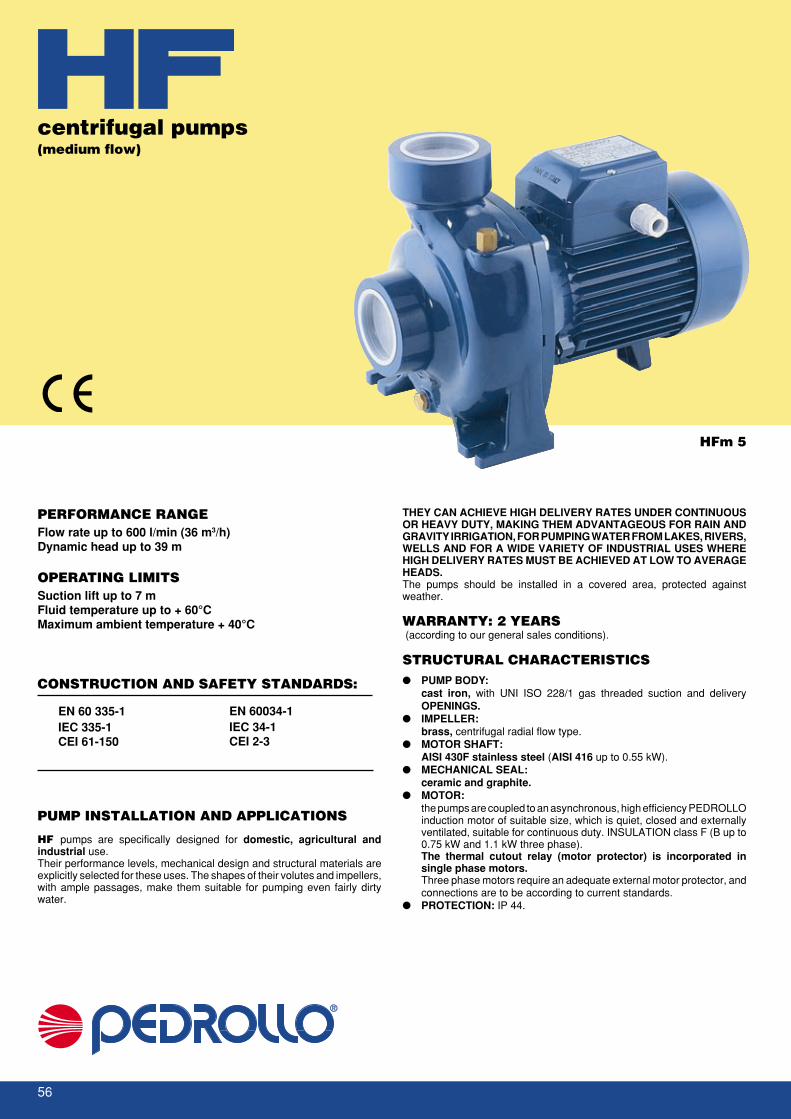
EN 60 335-1IEC 335-1CEI 61-150
EN 60034-1IEC 34-1CEI 2-3
56
HFm 5
CONSTRUCTION AND SAFETY STANDARDS:
centrifugal pumps(medium flow)
PUMP INSTALLATION AND APPLICATIONS
HF pumps are specifically designed for domestic, agricultural andindustrial use.Their performance levels, mechanical design and structural materials areexplicitly selected for these uses. The shapes of their volutes and impellers,with ample passages, make them suitable for pumping even fairly dirtywater.
PERFORMANCE RANGEFlow rate up to 600 l/min (36 m3/h)Dynamic head up to 39 m
OPERATING LIMITSSuction lift up to 7 mFluid temperature up to + 60°CMaximum ambient temperature + 40°C
THEY CAN ACHIEVE HIGH DELIVERY RATES UNDER CONTINUOUSOR HEAVY DUTY, MAKING THEM ADVANTAGEOUS FOR RAIN ANDGRAVITY IRRIGATION, FOR PUMPING WATER FROM LAKES, RIVERS,WELLS AND FOR A WIDE VARIETY OF INDUSTRIAL USES WHEREHIGH DELIVERY RATES MUST BE ACHIEVED AT LOW TO AVERAGEHEADS.The pumps should be installed in a covered area, protected againstweather.
WARRANTY: 2 YEARS (according to our general sales conditions).
STRUCTURAL CHARACTERISTICS� PUMP BODY:
cast iron, with UNI ISO 228/1 gas threaded suction and deliveryOPENINGS.
� IMPELLER:brass, centrifugal radial flow type.
� MOTOR SHAFT:AISI 430F stainless steel (AISI 416 up to 0.55 kW).
� MECHANICAL SEAL:ceramic and graphite.
� MOTOR:the pumps are coupled to an asynchronous, high efficiency PEDROLLOinduction motor of suitable size, which is quiet, closed and externallyventilated, suitable for continuous duty. INSULATION class F (B up to0.75 kW and 1.1 kW three phase).The thermal cutout relay (motor protector) is incorporated insingle phase motors.Three phase motors require an adequate external motor protector, andconnections are to be according to current standards.
� PROTECTION: IP 44.

57
0
0
l/min100 200 300 400 500 600
10 20 305 15 25 35
50 150 250 350 450 5500
5
10
15
20
25
50 1000
30
35
40
HF5C
HF5B
HF5AM
HF5BM
HF51B
HF50A
HF50B
HF51A
HF5A
HF70A
HF70B
HF60
0 US g.p.m.
Imp. g.p.m.
0
feet
10
20
30
40
50
60
70
50 100 150
120
80
90
100
110
m /h3
PERFORMANCE CHART AT n= 2900 1/min
PERFORMANCE DATA AT n= 2900 1/min
DIMENSIONS
Flow rate Q �����
Tota
l dyn
amic
hea
d H
(m) ���� �
0 3 6 9 12 15 18 21 24 30 36
0 50 100 150 200 250 300 350 400 500 6009 8.5 8.2 7.5 6.3 4.9 2.812 11.5 11.2 10.6 9.6 8 6
18.2 17.2 16 14 11.5 9 5.421.2 20.2 19 17 14.5 11.6 8.429 28 26.5 24.5 22 18.5 1533 32 30.5 28.5 26 22.5 1939 38 36.5 34.5 32 28.5 25
12.5 ––– 12 11.7 11 10.2 9.2 8 6.513.7 ––– 13.2 13 12.5 11.6 10.5 9.2 8 514.5 ––– 13.8 13.5 13.2 12.6 11.8 10.5 9.2 6.5 320.2 ––– 19.2 19 18 17 16 14 12 7.522.5 ––– 22 21.5 21 20 18.5 16.6 14.5 10
HFm 50B HF 50B 0.37 0.50HFm 50A HF 50A 0.55 0.75HFm 51B HF 51B 0.60 0.85HFm 51A HF 51A 0.75 1HFm 60 HF 60 1.1 1.5HFm 70B HF 70B 1.5 2––– HF 70A 2.2 3HFm 5C HF 5C 0.60 0.85HFm 5B HF 5B 0.75 1HFm 5A HF 5A 1.1 1.5HFm 5BM HF 5BM 1.1 1.5HFm 5AM HF 5AM 1.5 2
PUMP MODEL POWER
Single phase Three phase kW HP
PUMP MODEL DIMENSIONS mmSingle phase Three phase a f h h1 h2 n n1 w s
HFm 50B HF 50B 1 1/2" 1 1/2" 45 276 200 82 118 165 135 1 10HFm 50A ––– 1 1/2" 1 1/2" 45 283 200 82 118 165 135 1 10––– HF 50A 1 1/2" 1 1/2" 45 276 200 82 118 165 135 1 10HFm 51B-A HF 51B-A 1 1/2" 1 1/2" 45 300 225 92 133 190 160 4 10HFm 60 HF 60 1 1/2" 1 1/2" 48.5 347 269 114 155 216 171 12 12HFm 70B ––– 1 1/2" 1 1/2" 48.5 367 269 114 155 216 171 12 12––– HF 70B 1 1/2" 1 1/2" 48.5 347 269 114 155 216 171 12 12––– HF 70A 1 1/2" 1 1/2" 48.5 367 269 114 155 216 171 12 12HFm 5C-B-A HF 5C-B-A 2" 2" 60 332 238 97 141 196 160 14 11HFm 5BM HF 5BM 2" 2" 51 360 260 110 150 206 160 1 11HFm 5AM ––– 2" 2" 51 380 260 110 150 206 160 1 11––– HF 5AM 2" 2" 51 360 260 110 150 206 160 1 11
DN1 DN2
H(m)
Qm3/hl/min
Q = FLOW RATE H = TOTAL DYNAMIC HEAD IN METERS Curve tolerance according to ISO 2548.

EN 60 335-1IEC 335-1CEI 61-150
EN 60034-1IEC 34-1CEI 2-3
58
HF 6AR
CONSTRUCTION AND SAFETY STANDARDS:
PUMP INSTALLATION AND APPLICATIONSHF pumps are specifically designed for domestic, agricultural andindustrial use.Their performance levels, mechanical design and structural materials areexplicitly selected for these uses.The shapes of their volutes and impellers, with ample passages, make themsuitable for pumping even fairly dirty water.
PERFORMANCE RANGEFlow rate up to 1800 l/min (108 m3/h)Dynamic head up to 24.5 m
OPERATING LIMITSSuction lift up to 7 mFluid temperature up to + 60°CMaximum ambient temperature + 40°C
THEY CAN ACHIEVE HIGH DELIVERY RATES UNDER CONTINUOUSOR HEAVY DUTY, MAKING THEM ADVANTAGEOUS FOR RAIN ANDGRAVITY IRRIGATION, FOR PUMPING WATER FROM LAKES, RIVERS,WELLS AND FOR A WIDE VARIETY OF INDUSTRIAL USES WHEREHIGH DELIVERY RATES MUST BE ACHIEVED AT LOW TO AVERAGEHEADS.The pumps should be installed in a covered area, protected againstweather.
WARRANTY: 2 YEARS (according to our general sales conditions).
STRUCTURAL CHARACTERISTICS� PUMP BODY: cast iron, with UNI ISO 228/1 gas threaded suction
and delivery OPENINGS.� IMPELLER: brass, centrifugal radial flow type.� MOTOR SHAFT:
AISI 430F stainless steel.� MECHANICAL SEAL: ceramic and graphite.� MOTOR:
the pumps are coupled to an asynchronous, high efficiency PEDROLLOinduction motor of suitable size, which is quiet, closed and externallyventilated, suitable for continuous duty. INSULATION class F (B up to0.75 kW).The thermal cutout relay (motor protector) is incorporated insingle phase motors up to 1.5 kW.The remaining single phase motors and all three phase motors requirean adequate external motor protector, and connections are to beaccording to current standards.
� PROTECTION: IP 44.
centrifugal pumps(high flow)

59
60
0
5
10
15
20
0
0
l/min200 400 600 800 1000
10 3020 40 50
0 50 100 150 200
25
30
1400 1600 18001200
70 9080 100 110
0 US g.p.m.
Imp. g.p.m.
50 100 150 200 250 300
250 300 350
350 400 450
0
feet
10
20
30
40
50
60
70
80
90
m /h3
HF4
HF6A-6AR
HF6B-6BR
HF6C-6CR
HF8A
HF8B
HF20A
HF20B
PERFORMANCE CHART AT n= 2900 1/min
PERFORMANCE DATA AT n= 2900 1/min
DIMENSIONS
Flow rate Q �����
Tota
l dyn
amic
hea
d H
(m) ���� �
Q = FLOW RATE H = TOTAL DYNAMIC HEAD IN METERS Curve tolerance according to ISO 2548.
10 9.8 9.3 8.7 8 7 6 4.7 311.9 –– 11.7 11.3 10.7 10.2 9.2 8 6.7 5 314.7 –– 14.5 14 13.5 12.8 12 11 9.7 8.2 6.7 518.5 –– 18.1 17.8 17.2 16.8 16 15 13.8 12.2 10.5 8.3 611.9 –– 11.7 11.3 10.7 10.2 9.2 8 6.7 5 314.7 –– 14.5 14 13.5 12.8 12 11 9.7 8.2 6.7 518.5 –– 18.1 17.8 17.2 16.8 16 15 13.8 12.2 10.5 8.3 621.5 –– 21 20.7 20 19.5 18.8 17.8 16.5 15 13.5 11.2 924.5 –– 24 23.5 23 22.5 21.8 20.8 19.5 18.3 16.8 15 1316 –– –– –– 15.5 15.4 15.3 15.2 15 14.5 14 13 12 10.7 9 7 4.8 219 –– –– –– 18.5 18.4 18.3 18.2 18 17.5 17 16.2 15.2 13.7 12 10 7.8 5 2
PUMP MODEL POWER
Single phase Three phase kW HP
0 6 12 18 24 30 36 42 48 54 60 66 72 78 84 90 96 102 108
0 100 200 300 400 500 600 700 800 900 1000 1100 1200 1300 1400 1500 1600 17001800
Qm3/hl/min
HFm 4 HF 4 0.75 1HFm 6C HF 6C 1.1 1.5HFm 6B HF 6B 1.5 2––– HF 6A 2.2 3HFm 6CR HF 6CR 1.1 1.5HFm 6BR HF 6BR 1.5 2HFm 6AR HF 6AR 2.2 3HFm 8B HF 8B 3 4––– HF 8A 4 5.5HFm 20B HF 20B 3 4––– HF 20A 4 5.5
Hm
PUMP MODEL DIMENSIONS mmSingle phase Three phase a f h h1 h2 n n1 w s
HFm 4 HF 4 2 1/2" 2 1/2" 55 323 240 97 143 190 155 - 10HFm 6C HF 6C 3" 3" 68 385 312 120 192 240 190 6 12HFm 6B ––– 3" 3" 68 405 312 120 192 240 190 6 12––– HF 6B 3" 3" 68 385 312 120 192 240 190 6 12––– HF 6A 3" 3" 68 405 312 120 192 240 190 6 12HFm 6CR HF 6CR 4" 4" 70 387 312 120 192 240 190 6 12HFm 6BR ––– 4" 4" 70 407 312 120 192 240 190 6 12––– HF 6BR 4" 4" 70 387 312 120 192 240 190 6 12HFm 6AR ––– 4" 4" 70 430 312 120 192 240 190 6 12––– HF 6AR 4" 4" 70 407 312 120 192 240 190 6 12HFm 8B ––– 4" 4" 80 475 312 132 180 245 190 30 14––– HF 8B 4" 4" 80 429 312 132 180 245 190 30 14––– HF 8A 4" 4" 80 475 312 132 180 245 190 30 14HF m20B ––– 4" 4" 80 475 312 132 180 245 190 30 14––– HF 20B 4" 4" 80 429 312 132 180 245 190 30 14––– HF 20A 4" 4" 80 475 312 132 180 245 190 30 14
DN1 DN2

EN 60 335-1IEC 335-1CEI 61-150
EN 60034-1IEC 34-1CEI 2-3
60
NF 128
CONSTRUCTION AND SAFETY STANDARDS:
centrifugal pumps(with flanged connections)
PUMP INSTALLATION AND APPLICATIONSNF pumps are specifically designed for domestic, agricultural andindustrial use.Their performance levels, mechanical design and structural materials arespecifically selected for these uses.The shape of their volutes and impellers, with ample passages, make themsuitable for pumping even fairly dirty water.
PERFORMANCE RANGEFlow rate up to 1200 l/min (72 m3/h)Dynamic head up to 22.5 m
OPERATING LIMITSSuction lift up to 7 mFluid temperature up to + 60°CMaximum ambient temperature + 40°C
THEY CAN ACHIEVE HIGH DELIVERY RATES UNDER CONTINUOUSOR HEAVY DUTY, MAKING THEM ADVANTAGEOUS FOR RAIN ANDGRAVITY IRRIGATION, FOR PUMPING WATER FROM LAKES, RIVERS,WELLS AND FOR A WIDE VARIETY OF INDUSTRIAL USES WHEREHIGH DELIVERY RATES MUST BE ACHIEVED AT LOW TO AVERAGEHEADS.The pumps should be installed in a covered area, protected againstweather.
WARRANTY: 2 YEARS (according to our general sales conditions).
STRUCTURAL CHARACTERISTICS� PUMP BODY:
cast iron, with UNI ISO 228/1 gas threaded suction and deliveryFLANGES.
� IMPELLER:brass, centrifugal radial flow type.
� MOTOR SHAFT:AISI 430F stainless steel.
� MECHANICAL SEAL:ceramic and graphite.
� MOTOR:the pumps are coupled to an asynchronous, high efficiency PEDROLLOinduction motor of suitable size, which is quiet, closed and externallyventilated, suitable for continuous duty. INSULATION class F (B up to0.75 kW and 1.1 kW three phase).The thermal cutout relay (motor protector) is incorporated insingle phase motors.The remaining single phase motors and all three phase motors requirean adequate external motor protector, and connections must accordingto current standards.
� PROTECTION: IP 44.

61
fa
DN2
DN
1
w2w1
n
sn1
h1
h
h2
h3
0
0
100 200 300 400 500 600 700 800 900 1000 1100 1200
10 3020 40 6050 70
0
5
10
15
20
25
5 15 25 35 45 55 65 75
0 US g.p.m.
Imp. g.p.m.
50 100 150 200 250 300
0
feet
10
20
30
40
50
60
70
0 50 100 150 200 250
NF129A
NF129B
NF128B
NF130ANF130B
NF130C
NF128ANF128AR
PERFORMANCE CHART AT n= 2900 1/min
PERFORMANCE DATA AT n= 2900 1/min
DIMENSIONS
Flow rate Q �����
Tota
l dyn
amic
hea
d H
(m) ���� �
0 6 9 12 15 18 21 24 30 36 42 48 54 60 66 72
0 100 150 200 250 300 350 400 500 600 700 800 900 1000 1100 1200
12.5 12 11.7 11 10.2 9.2 8 6.513.7 13.2 13 12.5 11.6 10.5 9.2 8 514.5 13.8 13.5 13.2 12.6 11.5 10.5 9.2 6.5 320.2 19.2 19 18 17 16 14 12 7.522.5 22 21.5 21 20 18.5 16.6 14.5 1011.9 –– –– 11.7 11.5 11.3 11.1 10.7 10.2 9.1 8 6.7 5 314.7 –– –– 14.5 14.2 14 13.7 13.5 13.2 12 11 9.7 8.2 6.7 518.5 –– –– 18.1 18 17.8 17.5 17.2 16.8 16 15 13.8 12.2 10.5 8.3 6
NFm 128B NF 128B 0.60 0.85NFm 128A NF 128A 0.75 1NFm 128AR NF 128AR 1.1 1.5NFm 129B NF 129B 1.1 1.5NFm 129A NF 129A 1.5 2NFm 130C NF 130C 1.1 1.5NFm 130B NF 130B 1.5 2––– NF 130A 2.2 3
PUMP MODEL POWER
Single phase Three phase kW HP
PUMP MODEL DIMENSIONS mm
Single phase Three phase a f h h1 h2 h3 n n1 w1 w2 s
NFm 128B NF 128B 2" 2" 65 344 271 97 167 264 196 160 8 60 12NFm 128A NF 128A 2" 2" 65 344 271 97 167 264 196 160 8 60 12NFm 128AR NF 128AR 2" 2" 65 344 271 97 167 264 196 160 8 60 12NFm 129B NF 129B 2" 2" 56 372 276 110 159 269 206 160 1 62 11NFm 129A ––– 2" 2" 56 392 276 110 159 269 206 160 1 62 11––– NF 129A 2" 2" 56 372 276 110 159 269 206 160 1 62 11NFm 130C NF 130C 3" 3" 71 390 320 120 193 313 240 190 6 66 12NFm 130B ––– 3" 3" 71 410 320 120 193 313 240 190 6 66 12––– NF 130B 3" 3" 71 390 320 120 193 313 240 190 6 66 12––– NF 130A 3" 3" 71 410 320 120 193 313 240 190 6 66 12
DN1 DN2
H(m)
Qm3/hl/min
Q = FLOW RATE H = TOTAL DYNAMIC HEAD IN METERS Curve tolerance according to ISO 2548.

62
EN 60 335-1IEC 335-1CEI 61-150
EN 60034-1IEC 34-1CEI 2-3
EN 60034-1IEC 34-1CEI 2-3
PERFORMANCE RANGEFlow rate up to 2400 l/min (144 m3/h)Dynamic head up to 85 m
OPERATING LIMITSSuction lift up to 7 mFluid temperature up to + 60°CMaximum ambient temperature + 40°CMax operating pressure 10 bar
PUMP INSTALLATION AND APPLICATIONSThese pumps are recommended for clean water and fluids which are notchemically aggressive to the pump components. THEY ARE MAINLYUSED FOR CIVIL, INDUSTRIAL AND AGRICULTURAL APPLICATIONS,WHERE THEY MAKE THE MOST OF THEIR STURDINESS ANDDEPENDABILITY. They are manufactured to EN 733 - DIN 24255standards. Overall dimensions, sizes and positions of suction and deliveryopenings, support feet and performance comply with these standards.Theirstructural shape allows dismantling without disconnecting the pump bodyfrom the pipeline (back pull out), making them easy to use in widely varyingconditions.They should be installed in a covered area, protected against weather.
WARRANTY: 2 YEARS(according to our general sales conditions).
STRUCTURAL CHARACTERISTICS:� PUMP BODY:cast iron, manufactured to
EN 733 - DIN 24255 and UNI 7467-NF E-44-111 standards,built with flanged suction and delivery openings (UNI 2236 PN10).
� PUMP BODY COVER: cast iron, which closes the rear pump body andhouses the mechanical seal.
� IMPELLER: brass (cast iron for F 50/200-250, F 65/125-160-200).� MOTOR SHAFT: AISI 430F stainless steel.� MECHANICAL SEAL: ceramic and graphite.� MOTOR:
the pumps are coupled to an asynchronous, high efficiency PEDROLLOinduction motor of suitable size, which is quiet, closed and externallyventilated, suitable for continuous duty.INSULATION class F.Motors require an adequate external motor protector, and connectionsare to be according to current standards.
� PROTECTION:IP 44.
SPECIAL FEATURES ON REQUEST:
⇒ AISI 316 stainless steel motor shaft⇒ mechanical seal with different materials⇒ IP 55 protection⇒ other voltages⇒ 60 Hz frequency⇒ for higher temperature pumped liquids⇒ for use in areas with a higher temperature
CONSTRUCTION AND SAFETY STANDARDS:
F 50/250A
standardized centrifugal pumps(EN 733 - DIN 24255)

63
100 1000 l/min500 2000
100
50
feet
10200 300 400 600 800 1500
15
150
20
30
40
60
70
80
90
120
F 32/160
F 32/200H
F 32/200
F 40/160
F 50/250
F 40/200
F 50/160F 65/160
F 65/125
F 50/125
F 50/200
F 65/200
50
50
100
100
200 300
200
400
300
500
400
609
200
100
50
9042302115126
PERFORMANCE CHART AT n= 2900 1/min
Flow rate Q �����
Tota
l dyn
amic
hea
d H
(m) ���� �

64
PERFORMANCE CHART AT n= 2900 1/min
0
0
l/min100
5 10 15 20 25
50 150 200 250 300 350 400 450
10
20
30
0 US g.p.m.50 100
Imp. g.p.m.
125
0
5
10
15
1
2
3
63
60
63
55
15
25
35
2
4
100
75
50
H (
feet
)N
PS
H (
feet
)P
2 (
HP)
20
2.5
1.5
3
400 50 100
55
60
3.5
7
1
3
5
CBA
F32/160C
F32/160B
F32/160A
η= 65.5%
m /h3
PERFORMANCE DATA AT n= 2900 1/min
Portata Q �����
Inpu
t pow
er P
2 (k
W)
NP
SH
(m
)To
tal d
ynam
ic h
ead
H (m
) ���� �
25 24 23 21 19 16 13
31 30 29 28 26 23.5 20 16
38 37 36 34 32 30 27.5 24 20
0 6 9 12 15 18 21 24 27
0 100 150 200 250 300 350 400 450Single phase Three phase kW HP
PUMP MODEL POWER
Fm 32/160C F 32/160C 1.5 2
Fm 32/160B F 32/160B 2.2 3
Fm 32/160A F 32/160A 3 4
Q = FLOW RATE H = TOTAL DYNAMIC HEAD IN METERS
Qm3/h
l/min
H(m)
Curve tolerance according to ISO 2548.

65
PERFORMANCE CHART AT n= 2900 1/min
H (
feet
)N
PS
H (
feet
)P
2 (
HP)
2
3
4
5
6
7
2
3
4
5
6
7
8
9
10
30
40
50
60
0 50 100
0 50 100feet
80
100
120
140
160
180
25
35
45
5557
57
5550
45
55
20
0
0
100 200 300 400 500
5 10 15 20 25 30
0
5
10
15
207
1
3
5
CBA
F32/200C
η= 59%F32/200B
F32/200A
PERFORMANCE DATA AT n= 2900 1/min
Flow rate Q �����
Inpu
t pow
er P
2 (k
W)
NP
SH
(m
)To
tal d
ynam
ic h
ead
H (m
) ���� �
Single phase Three phase kW HP
PUMP MODEL POWER
46 44 43 41.5 40 38 36 34 31.5
54 52 50.5 49 47 45 43 41 38.5 36
60 57 56.5 56 55 53 52 50 47 44
Fm 32/200C F 32/200C 4 5.5
––– F 32/200B 5.5 7.5
––– F 32/200A 7.5 10
0 6 9 12 15 18 21 24 27 30
0 100 150 200 250 300 350 400 450 500
Q = FLOW RATE H = TOTAL DYNAMIC HEAD IN METERS
Qm3/hl/min
H(m)
Curve tolerance according to ISO 2548.

66
PERFORMANCE CHART AT n= 2900 1/min
0
2
4
6
0
5
10
15
H (
feet
)N
PS
H (
feet
)P
2 (
HP)
1
3
5
30
40
50
60 feet
80
100
120
140
160
180
25
35
45
55
20
0 50
0 50
0
0
100 200 300
5 10 15 20
50 150 250
2
3
4
2.0
2.5
3.0
3.5
4.0
4.5
5.0
5.5
BH
AH
F32/200BH
F32/200AH
η= 54%
45
50
52.5
52.5
PERFORMANCE DATA AT n= 2900 1/min
Flow rate Q �����
Inpu
t pow
er P
2 (k
W)
NP
SH
(m
)To
tal d
ynam
ic h
ead
H (m
) ���� �
Q = FLOW RATE H = TOTAL DYNAMIC HEAD IN METERS
49 45 42 39 34 28
59 55 52 49 44 38
Fm 32/200BH F 32/200BH 3 4
Fm 32/200AH F 32/200AH 4 5.5
0 6 9 12 15 18
0 100 150 200 250 300
Qm3/hl/min
H(m)
Curve tolerance according to ISO 2548.
Single phase Three phase kW HP
PUMP MODEL POWER

67
PERFORMANCE CHART AT n= 2900 1/min
0
6
2
H (
feet
)N
PS
H (
feet
)P
2 (
HP)
4
5
3
0
10
20
30
40
50
0
0
20
50 100 150
40
60
80
100
120
140
0 50 100 150
72
72
6560
68
74
0
0
100 200 300 400 500 600
5
700
10 15 20 25 30 35 40 45
2
4
0
5
10
15
1.0
2.5
4.0
C
F40/160C
F40/160B
F40/160A
B
A
74η= 75%
PERFORMANCE DATA AT n= 2900 1/min
Flow rate Q �����
Inpu
t pow
er P
2 (k
W)
NP
SH
(m
)To
tal d
ynam
ic h
ead
H (m
) ���� �
27 27 26.5 26 25.5 25 22.5 19 14
32 32 31.5 31 30.5 30 27.5 24 20
38 38 37.8 37 36.5 36 33.5 30 26 20
Fm 40/160C F 40/160C 2.2 3
Fm 40/160B F 40/160B 3 4
––– F 40/160A 4 5.5
0 6 9 12 15 18 24 30 36 42
0 100 150 200 250 300 400 500 600 700
Q = FLOW RATE H = TOTAL DYNAMIC HEAD IN METERS
Qm3/h
l/min
H(m)
Curve tolerance according to ISO 2548.
Single phase Three phase kW HP
PUMP MODEL POWER

68
PERFORMANCE CHART AT n= 2900 1/min
0
5
7
H (
feet
)N
PS
H (
feet
)P
2 (
HP)
10
6
8
9
20
30
40
50
60
0 50 100 150
80
100
120
140
160
180
0 50 100 150
5054
63
63
6058
60
58
25
35
45
55
0
0
100 200 300 400 500 600
5
700
10 15 20 25 30 35 40 45
1
2
3
4
0
5
10
3
5
8
4
6
7
F40/200A
A
F40/200B
B
η= 66%
PERFORMANCE DATA AT n= 2900 1/min
Flow rate Q �����
Inpu
t pow
er P
2 (k
W)
NP
SH
(m
)To
tal d
ynam
ic h
ead
H (m
) ���� �
48 47 46 45 43.5 42 39 35 30 24
56 54 53 52 51 49 46 42 37 32
F 40/200B 5.5 7.5
F 40/200A 7.5 10
PUMP MODEL POWER
Three phase kW HP
0 6 9 12 15 18 24 30 36 42
0 100 150 200 250 300 400 500 600 700
Q = FLOW RATE H = TOTAL DYNAMIC HEAD IN METERS
Qm3/h
l/min
H(m)
Curve tolerance according to ISO 2548.

69
PERFORMANCE CHART AT n= 2900 1/min
2
3
5
H (
feet
)N
PS
H (
feet
)P
2 (
HP)4
US g.p.m.500 100 150 200 250 300
10
20
300 50 100 150 200
20
Imp. g.p.m.250
0
5
15
25
40
60
80
100 200 300 400 500 600 700 800 900 1000 1100
5 10 15 20 25 30 35 40 45 50 55 60 65
0
1200
70
0
0 75
2
3
0
1
4
0
5
10
2
3
4
F50/125A
A
F50/125B
F50/125C
75
7370
6560
75
73
B
C
η= 77%
PERFORMANCE DATA AT n= 2900 1/min
Flow rate Q �����
Inpu
t pow
er P
2 (k
W)
NP
SH
(m
)To
tal d
ynam
ic h
ead
H (m
) ���� �
Fm 50/125C F 50/125C 2.2 3
Fm 50/125B F 50/125B 3 4
––– F 50/125A 4 5.5
0 18 24 30 36 42 48 54 60 66 72
0 300 400 500 600 700 800 900 1000 1100 1200
18.5 17.5 17 16.5 15.5 14.8 13.5 12 10.5 8.2 6
21.5 20.7 20 19.5 18.8 17.8 16.5 15 13.5 11.2 9
24.5 23.5 23 22.5 21.8 20.8 19.5 18.3 16.8 15 13
Q = FLOW RATE H = TOTAL DYNAMIC HEAD IN METERS
Qm3/h
l/min
H(m)
Curve tolerance according to ISO 2548.
Single phase Three phase kW HP
PUMP MODEL POWER

70
PERFORMANCE CHART AT n= 2900 1/min
5
6
9
H (
feet
)N
PS
H (
feet
)P
2 (
HP)
7
8
10
4
US g.p.m.500 100 150 200 250 300
10
20
30
400 50 100 150 200
50
Imp. g.p.m.250
7065
55 60
72
73
73
15
25
35
100
100 200 300 400 500 600 700 800 900 1000 1100
5 10 15 20 25 30 35 40 45 50 55 60 65
1200
70
0
0
2
3
0
1
4
0
5
10
3
5
7
6
4
F50/160A
AB
C
F50/160B
F50/160C
η= 75%
PERFORMANCE DATA AT n= 2900 1/min
Flow rate Q �����
Inpu
t pow
er P
2 (k
W)
NP
SH
(m
)To
tal d
ynam
ic h
ead
H (m
) ���� �
Fm 50/160C F 50/160C 4 5.5
––– F 50/160B 5.5 7.5
––– F 50/160A 7.5 10
0 18 24 30 36 42 48 54 60 66
0 300 400 500 600 700 800 900 1000 1100
27 27 26.5 25 24.5 23 20 18.5 16
33 32 31.7 31 30 29 27 26 24 21
38 37 36.8 36.5 36 34 33 32 30 27
Q = FLOW RATE H = TOTAL DYNAMIC HEAD IN METERS
Qm3/h
l/min
H(m)
Curve tolerance according to ISO 2548.
Single phase Three phase kW HP
PUMP MODEL POWER

71
PERFORMANCE CHART AT n= 2900 1/min
H (
feet
)N
PS
H (
feet
)P
2 (
HP)
15
US g.p.m.1000 200 300 400
0 100 200 300 400 Imp. g.p.m.
0 10 20 30 40 50 60 70 80 90 100 110
110
120
130
140
180
5
170
160
150
190
200
210
10
15
20
30
35
40
45
50
55
60
65
0 200 400 600 800 1000 1200 1400 1600 1800
0
2
4
6
5
10
15
20
6569
7071
73
73
71
F50/200A
ABC
F50/200C
F50/200B
20
25
10
η= 76%
PERFORMANCE DATA AT n= 2900 1/min
Flow rate Q �����
Inpu
t pow
er P
2 (k
W)
NP
SH
(m
)To
tal d
ynam
ic h
ead
H (m
) ���� �
PUMP MODEL POWER 0 24 36 48 60 72 84 96 102 108
Three phase kW HP 0 400 600 800 1000 1200 1400 1600 1700 1800
F 50/200C 11 15 46 46 45 44 42 39 36 33
F 50/200B 15 20 54 54 53 52 50 47 44 40 38
F 50/200A 18.5 25 63 63 62 61 60 57 54 50 48 45
Q = FLOW RATE H = TOTAL DYNAMIC HEAD IN METERS
Qm3/h
l/min
H(m)
Curve tolerance according to ISO 2548.

72
PERFORMANCE CHART AT n= 2900 1/min
15H
(fe
et)
NP
SH
(fe
et)
P2
(HP
)
20
30
40
50
60
70
80
90
100
150
200
250
US g.p.m.500 100 150 200
Imp. g.p.m.0 50 100 150 200
250
100
300
0 100 200 300 400 500 600 700 800 900
0 5 10 15 20 25 30 35 40 45 50 55
1000
60
6560
50
l/min
0
10
5
15
0
2
4
6
5
8
11
14
17
20
A
F50/250A
F50/250B
F50/250C
F50/250D
B
CD
20
25
10
η= 69%
PERFORMANCE DATA AT n= 2900 1/min
Flow rate Q �����
Inpu
t pow
er P
2 (k
W)
NP
SH
(m
)To
tal d
ynam
ic h
ead
H (m
) ���� �
PUMP MODEL POWER 0 18 24 30 36 42 48 54 60
Three phase kW HP 0 300 400 500 600 700 800 900 1000
F 50/250D 9.2 12.5 51 51 49 47 44 41 37 32
F 50/250C 11 15 59 59 58 57 54 51 47 42
F 50/250B 15 20 72 72 71 70 69 67 65 62 59
F 50/250A 18.5 25 85 85 84 83 82 80 77 76 73
Q = FLOW RATE H = TOTAL DYNAMIC HEAD IN METERS
Qm3/h
l/min
H(m)
Curve tolerance according to ISO 2548.

73
PERFORMANCE CHART AT n= 2900 1/min
3
7
H (
feet
)N
PS
H (
feet
)P
2 (
HP)
9
4
10
5
6
8
0
10
5
15
US g.p.m.1000 200 300 400 500 600
10
0 100 200 300 400
70
Imp. g.p.m.500
0 200 400 600 800 1000 1200 1400 1600 1800 2000 2200
0 10 20 30 40 50 60 70 80 90 100 110 120 130
2400
140 150
40
45
50
55
60
65
75
80
35
15
20
25
3
4
5
6
2
7
80
1
2
3
4
5
78 8387
87
A
F65/125A
F65/125B
F65/125C
BC
η= 88%
PERFORMANCE DATA AT n= 2900 1/min
Flow rate Q �����
Inpu
t pow
er P
2 (k
W)
NP
SH
(m
)To
tal d
ynam
ic h
ead
H (m
) ���� �
PUMP MODEL POWER 0 36 48 60 72 84 96 108 120 132
Three phase kW HP 0 600 800 1000 1200 1400 1600 1800 2000 2200
F 65/125C 4 5.5 16 16 16 15.5 14.5 13.5 12.5 11
F 65/125B 5.5 7.5 18 18 18 18 17 16.5 15.5 14.5 13
F 65/125A 7.5 10 23 23 23 23 22.5 22.5 22 21 19.5 18
H(m)
Q = FLOW RATE H = TOTAL DYNAMIC HEAD IN METERS
Qm3/h
l/min
Curve tolerance according to ISO 2548.

74
PERFORMANCE CHART AT n= 2900 1/min
0
H (
feet
)N
PS
H (
feet
)P
2 (
HP)15
10
20
2
4
6
8
10
20
5
15
25
US g.p.m.1000 200 300 400 500 600
10
20
30
40
500 100 200 300 400
50
150
100
Imp. g.p.m.500
0 200 400 600 800 1000 1200 1400 1600 1800 2000 2200
0 10 20 30 40 50 60 70 80 90 100 110 120 130
2400
140 150
75
78
7060 65
8078
80
45
35
25
15
5
7
9
11
13
15
F65/160A
A
F65/160B
F65/160C
BC
η= 81%
PERFORMANCE DATA AT n= 2900 1/min
Flow rate Q �����
Inpu
t pow
er P
2 (k
W)
NP
SH
(m
)To
tal d
ynam
ic h
ead
H (m
) ���� �
PUMP MODEL POWER 0 36 48 60 72 84 96 108 120 132 144
Three phase kW HP 0 600 800 1000 1200 1400 1600 1800 2000 2200 2400
F 65/160C 9.2 12.5 32 32 32 32 32 30 29 27 25 22
F 65/160B 11 15 37 36.5 36.5 36 35.5 34 33 31 29 26 23
F 65/160A 15 20 41 40.5 40.5 40 39.5 39 37.5 36 34 31 28
H(m)
Q = FLOW RATE H = TOTAL DYNAMIC HEAD IN METERS
Qm3/h
l/min
Curve tolerance according to ISO 2548.

75
PERFORMANCE CHART AT n= 2900 1/min
15H
(fe
et)
NP
SH
(fe
et)
P2
(HP
)20
10
25
0
10
5
15
US g.p.m.1000 200 300 400 500
0 100 200 300 400
100
Imp. g.p.m.
0 10 20 30 40 50 60 70 80 90 100 110 120
150
110
120
130
140
160
170
180
30
35
40
45
50
55
0 200 400 600 800 1000 1200 1400 1600 1800 2000
0
1
2
3
4
5
6
8
10
12
14
16
18
20
65
75
70
76
76
75
F65/200A
A
F65/200B
B
η= 77%
PERFORMANCE DATA AT n= 2900 1/min
Flow rate Q �����
Inpu
t pow
er P
2 (k
W)
NP
SH
(m
)To
tal d
ynam
ic h
ead
H (m
) ���� �
PUMP MODEL POWER 0 24 36 48 60 72 84 96 108 120 126
Three phase kW HP 0 400 600 800 1000 1200 1400 1600 1800 2000 2100
F 65/200B 15 20 46 46 46 45.5 45 44 42.5 41 38.5 35.5
F 65/200A 18.5 25 52 52 52 51.5 51 50 49 47 44.5 41.5 40
H(m)
Q = FLOW RATE H = TOTAL DYNAMIC HEAD IN METERS
Qm3/h
l/min
Curve tolerance according to ISO 2548.

76
DN DN
Q
D
Q
D
FLANGES D Q HOLES MAXDN Nº Ø THICKNESSmm mm mm mm mm32 140 100 4 18 1840 150 110 4 18 1850 165 125 4 18 2065 185 145 4 18 2080 200 160 8 18 22
Fm 32/160C F 32/160C 50 32 80 405 292 132 160 242 190 240 35 35 14
Fm 32/160B ––– 50 32 80 430 292 132 160 242 190 240 35 35 14
––– F 32/160B 50 32 80 405 292 132 160 242 190 240 35 35 14
Fm 32/160A F 32/160A 50 32 80 430 292 132 160 242 190 240 35 35 14
Fm 32/200C ––– 50 32 80 525 340 160 180 264 190 250 35 35 14
––– F 32/200C 50 32 80 481 340 160 180 264 190 250 35 35 14
––– F 32/200B 50 32 80 525 340 160 180 264 190 250 35 35 14
––– F 32/200A 50 32 80 525 340 160 180 264 190 250 35 35 14
Fm 40/160C ––– 65 40 80 430 292 132 160 240 190 240 35 35 14
––– F 40/160C 65 40 80 405 292 132 160 240 190 240 35 35 14
Fm 40/160B ––– 65 40 80 476 292 132 160 240 190 240 35 35 14
––– F 40/160B 65 40 80 430 292 132 160 240 190 240 35 35 14
––– F 40/160A 65 40 80 476 292 132 160 240 190 240 35 35 14
Fm 50/125C ––– 65 50 100 450 292 132 160 242 190 240 35 35 14
––– F 50/125C 65 50 100 434 292 132 160 242 190 240 35 35 14
Fm 50/125B ––– 65 50 100 495 292 132 160 242 190 240 35 35 14
––– F 50/125B 65 50 100 450 292 132 160 242 190 240 35 35 14
––– F 50/125A 65 50 100 495 292 132 160 242 190 240 35 35 14
DN1 DN2PUMP MODEL
Single phase Three phase a f h h1 h2 n n1 n2 w1 w2 s
––– F 40/200B 65 40 100 545 340 160 180 275 212 265 35 35 14
––– F 40/200A 65 40 100 545 340 160 180 275 212 265 35 35 14
DIMENSIONS (mm)
Fm 32/200BH F 32/200BH 50 32 80 481 340 160 180 264 190 250 35 35 14
Fm 32/200AH ––– 50 32 80 525 340 160 180 264 190 250 35 35 14
––– F 32/200AH 50 32 80 481 340 160 180 264 190 250 35 35 14

77
DN1 DN2PUMP MODEL
Single phase Three phase a f h h1 h2 n n1 n2 w1 w2 s
Fm 50/160C ––– 65 50 100 545 340 160 180 265 212 265 35 35 14
––– F 50/160C 65 50 100 501 340 160 180 265 212 265 35 35 14
––– F 50/160B 65 50 100 545 340 160 180 265 212 265 35 35 14
––– F 50/160A 65 50 100 545 340 160 180 265 212 265 35 35 14
––– F 50/200C 65 50 100 620 360 160 200 320 212 265 35 35 14
––– F 50/200B 65 50 100 715 360 160 200 320 212 265 35 35 14
––– F 50/200A 65 50 100 715 360 160 200 320 212 265 35 35 14
––– F 50/250D 65 50 100 605 405 180 225 336 250 320 47.5 47.5 14
––– F 50/250C 65 50 100 605 405 180 225 336 250 320 47.5 47.5 14
––– F 50/250B 65 50 100 700 405 180 225 336 250 320 47.5 47.5 14
––– F 50/250A 65 50 100 700 405 180 225 336 250 320 47.5 47.5 14
––– F 65/125C 80 65 100 546 340 160 180 292 212 280 47.5 47.5 14
––– F 65/125B 80 65 100 592 340 160 180 292 212 280 47.5 47.5 14
––– F 65/125A 80 65 100 592 340 160 180 292 212 280 47.5 47.5 14
––– F 65/200B 80 65 100 722 405 180 225 340 250 320 47.5 47.5 14
––– F 65/200A 80 65 100 722 405 180 225 340 250 320 47.5 47.5 14
––– F 65/160C 80 65 100 625 360 160 200 300 212 280 47.5 47.5 14
––– F 65/160B 80 65 100 625 360 160 200 300 212 280 47.5 47.5 14
––– F 65/160A 80 65 100 720 360 160 200 300 212 280 47.5 47.5 14
DIMENSIONS (mm)

EN 60 335-1IEC 335-1CEI 61-150
EN 60034-1IEC 34-1CEI 2-3
78
CONSTRUCTION AND SAFETY STANDARDS:
PERFORMANCE RANGEFlow rate up to 80 l/min (4.8 m3/h)Dynamic head up to 77 m
OPERATING LIMITSMaximum operating depth 40 mMaximum fluid temperature + 40°C
PUMP INSTALLATION AND APPLICATIONSSK pumps should be used in clean water not containing abrasive substances.THEIR DEPENDABILITY AND ECONOMICAL NATURE MAKE THEMPARTICULARLY SUITABLE FOR DOMESTIC USE, ESPECIALLY FORTHE AUTOMATIC DISTRIBUTION OF WATER WORKING INCONJUNCTION WITH SMALL SURGE TANKS AND FOR GARDENINGIN GENERAL, ETC.. SK pumps can be installed in wells with a diameter ofno less than 4" (100 mm) for 4SK and 5" (125 mm) for 5SK. The pump islowered into the well by means of the delivery pipe until it is completelyimmersed (min. 50 cm, and at least one meter from the bottom of the well)even when working, as pump operation may obviously cause the level of the
4" - 5" peripheral submersible pumps(with anti-seize impeller housing)
liquid in the well to fall. It is advisable to secure the pump using a stainlesssteel or nylon cable connected to the special holes on the discharge head.
WARRANTY: 1 YEAR(according to our general sales conditions).
STRUCTURAL CHARACTERISTICS� DISCHARGE HEAD: with anti-seize impeller housing (patented) in
brass/stainless steel.� IMPELLER: brass, with radial peripheral blades.� MOTOR SLEEVE: AISI 304 stainless steel.� MOTOR SHAFT: AISI 416 stainless steel (AISI 430F for 5SK).� MOTOR: completely removable and rewindable enclosed induction
motor, in oil bath, with built-in thermal cutout relay (motor protector)to allow for considerable supply voltage fluctuations, ensures continuousoperation at the maximum power required by the pump, cooled externallyby the liquid being pumped. INSULATION class F.
� PROTECTION: IP 68.� CONTROL BOX: with capacitor, bipolar switch and overload cutout with
manual reset supplied as standard. Protection IP 64.� SUPPLY CABLE: 10 meters "H07 RN-F" neoprene submersible with
removable connector.� CHECK VALVE: incorporated in the pump body.
4SKm 100� EXTERNAL DIAMETER 96 mm for 4" wells.� 1" UNI ISO 228/1 gas DELIVERY OPENING.� graphite/alumina MECHANICAL SEAL.
5SKm 100, 5SKm 100M, 5SKm 150� EXTERNAL DIAMETER 120 mm for 5" wells.� 11/4" UNI ISO 228/1 gas DELIVERY OPENING.� graphite/stainless steel MECHANICAL SEAL.
SPECIAL FEATURE ON REQUEST:
⇒ 20 meters “H07 RN-F” supply cable.⇒ 15, 30 meters “H05 VV-F” supply cable.
This new series of submersible pumps is fittedwith a patented anti-seize system (ensuring pumpoperation, even after being left idle for long peri-ods), an oversized motor in a biodegradable, non-toxic, alimentary quality oil bath.

79
250
10 20 30 40 50453525150
0
5
1 2.5 4
0
10
20
30
40
50
60
70
0.5 1.5 3
55 60 65 70 75 80
2 3.5
85
4.5
0
0 US g.p.m.
5
10
Imp. g.p.m.
5 15 20
10 15
50
100
150
200
feet80
5
5SKm100
4SKm100
5SKm100M
5SKm150
0
PERFORMANCE CHART AT n= 2900 1/min
PERFORMANCE DATA AT n= 2900 1/min
Flow rate Q �����
Tota
l dyn
amic
hea
d H
(m) ���� �
DIMENSIONSDIMENSIONS mm
DN Ø L
4SKm 100 1" 96 4665SKm 100 1 1/4" 120 3135SKm 100M 1 1/4" 120 3135SKm 150 1 1/4" 120 313
PUMPMODEL
68 62 55 49 43 37 30 24 17 5
77 70 63.5 57 50 43.5 37 30 23 10
42 40 37.5 35 32.5 30 27.5 25 22.5 17.5 13 8 3
53 50 47.5 45 42 39 37 34 31 26 21 15 10
0 0.3 0.6 0.9 1.2 1.5 1.8 2.1 2.4 3.0 3.6 4.2 4.8
0 5 10 15 20 25 30 35 40 50 60 70 80Single phase kW HP
PUMP MODEL POWER
4SKm 100 0.75 1
5SKm 100 0.75 1
5SKm 100M 0.75 1
5SKm 150 1.1 1.5
Q = FLOW RATE H = TOTAL DYNAMIC HEAD IN METERS Curve tolerance according to ISO 2548.
H(m)
Qm3/h
l/min

EN 60 335-1IEC 335-1CEI 61-150
EN 60034-1IEC 34-1CEI 2-3
80
monoblock submersible pumps
PUMP INSTALLATION AND APPLICATIONSTHESE PUMPS ARE SUITABLE FOR PUMPING CLEAN WATER ORFLUIDS WITH A SAND CONTENT OF NOT MORE THAN 50 g/m
3. THEIR
HIGH PERFORMANCE AND DEPENDABILITY MAKE THEM SUITABLEFOR USE IN DOMESTIC, CIVIL AND INDUSTRIAL FIELDS, FOR THEAUTOMATIC DISTRIBUTION OF WATER WORKING IN CONJUNCTIONWITH SURGE TANKS, FOR GARDENING, FOR WASHING ANDPRESSURE-BOOSTING SYSTEMS, ETC.
PERFORMANCE RANGEFlow rate up to 80 l/min (4.8 m3/h)Dynamic head up to 90 m
OPERATING LIMITSMaximum fluid temperature +40°CMaximum sand content 50 g/m3
Maximum operating depth 20 m below water levelMaximum emptying level 90 mm from the bottom (75 mm up to 0.75 kW)
The pump can be installed either vertically or horizontally; when installedvertically in a well, it is advisable to secure the pump by using a stainlesssteel or nylon cable connected to the special eyebolt provided on thedischarge head.
WARRANTY: 1 YEAR (according to our general sales conditions).
STRUCTURAL CHARACTERISTICS
� EXTERNAL SLEEVE: AISI 304 stainless steel, with 11/4" gas thread deliveryopening UNI ISO 228/1.
� IMPELLERS AND DIFFUSERS: Noryl® "General Electric"technopolymer.
� DIAPHRAGMS: AISI 304 stainless steel, complete with anti-wear rings.� MOTOR SLEEVE: AISI 304 stainless steel.� MOTOR SHAFT: AISI 430F stainless steel (AISI 416 up to 0,75 kW).� MOTOR BRACKETS: brass.� DOUBLE MECHANICAL SEAL: silicon carbide/silicon carbide
(graphite and alumina up to 0,75 kW) on the pump side and sealing ringon the motor side (with barrier oil chamber to lubricate and cool the sealingsurfaces in the absence of water).
� BOLTS, SCREWS AND FILTER: AISI 304 stainless steel.� MOTOR: completely removable and rewindable enclosed induction
MOTOR, suitable for continuous duty. The thermal cutout relay (motorprotector) is incorporated in single phase motors.
� PROTECTION: IP 68.� SUPPLY CABLE: 20 meters "H07 RN-F" submersible with removable
connector.� CONTROL BOX: with capacitor and schuko plug in single phase motors.
Protection IP 64� EXTERNAL FLOAT SWITCH: if requested for single phase motors.
SPECIAL FEATURES ON REQUEST:
⇒ External float switch (for single phase versions)⇒ Control box for three phase versions
CONSTRUCTION AND SAFETY STANDARDS:
SUMO is born from a careful mechanical fluiddynamics design, the best synthesis of performan-ce, reliability, rugged construction and simplemaintenance

81
LDN
Ø
0 5 10 15
0
feet
50
350
0 US g.p.m.
Imp. g.p.m.
5 10 15 20
100
150
200
250
300SUMO2/15
SUMO2/11
SUMO2/7
0 10 30 40 50 7020 60 80
0 1 2 3 4 5
0
20
40
80
60
100
120
SUMO2/5
Flow rate Q �����
Tota
l dyn
amic
hea
d H
(m) ���� �
PERFORMANCE CHART AT n= 2900 1/min
PERFORMANCE DATA AT n= 2900 1/min
DIMENSIONSDIMENSIONS mm
PUMP MODEL DN Stage N° L Ø
Single phase Three phase
SUMO 2/5 1 1/4" 3 377 377 135
SUMO 2/7 1 1/4" 5 475 475 135
SUMO 2/11 1 1/4" 5 545 545 153
SUMO 2/15 1 1/4" 6 575 575 153
Q = FLOW RATE H = TOTAL DYNAMIC HEAD IN METERS Curve tolerance according to ISO 2548.
SUMOm 2/5 SUMO 2/5 0.45 0.6
SUMOm 2/7 SUMO 2/7 0.75 1
SUMOm 2/11 SUMO 2/11 1.1 1.5
SUMOm 2/15 SUMO 2/15 1.5 2
36 35 33 31 28 26 25 23 22 20 18 16 14
60 58 55 51 47 44 42 38 36 32 28 23 18
75 72 70 66 61 58 55 52 48 44 40 35 30
90 87 83 78 73 70 66 62 58 53 48 44 38
0 0.6 1.2 1.8 2.4 2.7 3 3.3 3.6 3.9 4.2 4.5 4.8
0 10 20 30 40 45 50 55 60 65 70 75 80
H(m)
Qm3/h
l/min
PUMP MODEL POWER
Single phase Three phase kW HP

EN 60 335-1IEC 335-1CEI 61-150
EN 60034-1IEC 34-1CEI 2-3
82
PERFORMANCE RANGEFlow rate up to 120 l/min (7.2 m3/h)Dynamic head up to 105 m
OPERATING LIMITSMaximum fluid temperature +40°CMaximum sand content 50 g/m3
Maximum operating depth 20 m below water levelMaximum emptying level 90 mm from the bottom
PUMP INSTALLATION AND APPLICATIONSTHESE PUMPS ARE SUITABLE FOR PUMPING CLEAN WATER ORFLUIDS WITH A SAND CONTENT OF NOT MORE THAN 50 g/m
3. THEIR
HIGH PERFORMANCE AND DEPENDABILITY MAKE THEM SUITABLEFOR USE IN DOMESTIC, CIVIL AND INDUSTRIAL FIELDS, FOR THEAUTOMATIC DISTRIBUTION OF WATER WORKING IN CONJUNCTIONWITH SURGE TANKS, FOR GARDENING, FOR WASHING ANDPRESSURE-BOOSTING SYSTEMS, ETC.
monoblock submersible pumps
The pump can be installed either vertically or horizontally; when installedvertically in a well, it is advisable to secure the pump by using a stainlesssteel or nylon cable connected to the special eyebolt provided on thedischarge head.
WARRANTY: 1 YEAR (according to our general sales conditions).
STRUCTURAL CHARACTERISTICS� EXTERNAL SLEEVE: AISI 304 stainless steel, with 11/4" gas thread delivery
opening UNI ISO 228/1.� IMPELLERS AND DIFFUSERS: Noryl® "General Electric"
technopolymer.� DIAPHRAGMS: stainless steel AISI 304, complete with anti-wear rings.� MOTOR SLEEVE: AISI 304 stainless steel.� MOTOR SHAFT: AISI 430F stainless steel.� MOTOR BRACKETS: brass.� DOUBLE MECHANICAL SEAL: silicon carbide/silicon carbide on the
pump side and sealing ring on the motor side (with barrier oil chamber tolubricate and cool the sealing surfaces in the absence of water).
� BOLTS, SCREWS AND FILTERS: AISI 304 stainless steel.� MOTOR: Completely removable and rewindable enclosed induction
MOTOR, suitable for continuous duty. The thermal cutout relay (motorprotector) is incorporated (up to 1.5 kW) in single phase motors.
� PROTECTION: IP 68.� SUPPLY CABLE: 20 meters "H07 RN-F" submersible with removable
connector.� CONTROL BOX: with capacitor and schuko plug in single phase
motors.Protection IP64.� EXTERNAL FLOAT SWITCH: if requested for single phase motors.
SPECIAL FEATURES ON REQUEST:
⇒ External float switch (for single phase versions).⇒ Control box for three phase versions.
CONSTRUCTION AND SAFETY STANDARDS:
SUMO is born from a careful mechanical fluiddynamics design, the best synthesis of performan-ce, reliability, rugged construction and simplemaintenance

83
0
0 5 10 15 20 25 30
5 10 20 2515
0
50
350
100
150
200
250
300
00
0
l/min10 20 30 40 50 60 70 80 90 100 110 120
1 2 3 4 5 6 7
20
40
60
80
100
0.5 1.5 2.5 3.5 4.5 5.5 6.5 7.5
120
130
8
SUMO4/22
SUMO4/15
SUMO4/11
m /h3
LDN
Ø
Flow rate Q �����
Tota
l dyn
amic
hea
d H
(m) ���� �
PERFORMANCE CHART AT n= 2900 1/min
0 0.6 1.2 1.8 2.4 3 3.6 4.2 4.8 5.4 6 6.6 7.2
0 10 20 30 40 50 60 70 80 90 100 110 120
SUMOm 4/11 SUMO 4/11 1.1 1.5
SUMOm 4/15 SUMO 4/15 1.5 2
SUMOm 4/22 SUMO 4/22 2.2 3
60 58 56 54 52 50 48 46 43 39 36 31 24
75 74 72 69 66 64 60 57 53 48 43 38 32
105 103 101 98 94 90 86 80 75 67 60 52 44
PUMP MODEL POWER
Single phase Three phase kW HP
PERFORMANCE DATA AT n= 2900 1/min
Q = FLOW RATE H = TOTAL DYNAMIC HEAD IN METERS Curve tolerance according to ISO 2548.
H(m)
Qm3/h
l/min
DIMENSIONSDIMENSIONS mm
PUMP MODEL DN Stage N° L Ø
Single phase Three phase
SUMO 4/11 1 1/4" 4 515 515 153
SUMO 4/15 1 1/4" 5 545 545 153
SUMO 4/22 1 1/4" 7 650 650 153

84
EN 60 335-1IEC 335-1CEI 61-150
EN 60034-1IEC 34-1CEI 2-3
EN 60 335-1IEC 335-1CEI 61-150
EN 60034-1IEC 34-1CEI 2-3
4" submersible pumps(sand resistant)
PERFORMANCE RANGEFlow rate up to 375 l/min (22.5 m3/h)Dynamic head up to 525 m
OPERATING LIMITSMaximum fluid temperature + 30°CMaximum sand content: 150 g/m3
Starts: max. 20/h
PUMP INSTALLATION AND APPLICATIONS
THESE PUMPS ARE SUITABLE FOR PUMPING CLEAN WATER ORFLUIDS WITH A SAND CONTENT OF NOT MORE THAN 150 g/m
3.
THEIR HIGH PERFORMANCE AND DEPENDABILITY MAKE THEMSUITABLE FOR USE IN DOMESTIC, CIVIL AND INDUSTRIAL FIELDS,FOR THE AUTOMATIC DISTRIBUTION OF WATER WORKING INCONJUNCTION WITH SURGE TANKS, FOR GARDENING IN GENERAL,FOR WASHING AND PRESSURE-BOOSTING SYSTEMS, AND FORFIRE-FIGHTING PURPOSES, ETC.
WARRANTY: 1 YEAR (according to our general sales conditions).
STRUCTURAL CHARACTERISTICS� DISCHARGE HEAD AND MOTOR BRACKET: brass
AISI 304 stainless steel for models 4SR1/45-64, 4SR1.5/46-60, 4SR2/50-70, 4SR4/46-60-78, 4SR6/42-56, 4SR8/42, 4SR10/26-35, 4SR12/29,4SR15/24.
� CHECK VALVE: AISI 304 stainless steel, high-resistance check valve,enables the weight of the column of water to be dispersed without stressto the impellers and diffusers, thus ensuring long pump life.
� IMPELLERS: Lexan® "General Electric" technopolymer.� DIFFUSERS: Noryl® "General Electric" technopolymer.� BOWL: AISI 304 stainless steel.� EXTERNAL SLEEVE: AISI 304 stainless steel.� PUMP SHAFT: AISI 304 stainless steel.� TRANSMISSION COUPLING: AISI 316L stainless steel.� BOLTS, SCREWS, FILTER AND CABLE GUARD: AISI 304 stainless
steel.� MOTOR: 4” submersible: water filled "Franklin Electric" motor or rewindable
oil bath "Pedrollo" motor.� PROTECTION: IP 68.� SUPPLY CABLE: 1.5 meters "FE4DM/T" submersible supply cable.
SPECIAL FEATURES ON REQUEST:
⇒ AISI 304 stainless steel discharged head and motor bracket for brassversion
⇒ for water with sand content above 150 g/m3
⇒ other voltages⇒ 60 Hz frequency
CONSTRUCTION AND SAFETY STANDARDS:
The exclusive patented design of the water end,thanks to the combination of the front housingwith the axial movement of the impellers,guarantees the pump against any damage causedby sand, including blocking.

85
1
10
100
1000
1 10 100 l/min5 50 500
5
50
500
feet
30
3
328
132
110
20 30 200 300
12 18
30
20
40
200
300
400
600700800900
1.3
1.1
2.6
2.2
13
11
26
22
1640
164
33
16
631.81.20.60.3
PERFORMANCE CHART AT n= 2900 1/min
Flow rate Q �����
Tota
l dyn
amic
hea
d H
(m) ���� �
best efficiency point (m3/h)
impellers number
pump name
4 SR 1 m /13
well Ø 4”
single phase motor (max 2.2 kW)

86
0
feet
0
450
0
5 10 15 20 25 30
0.2 0.4 0.6 0.8 1 1.2 1.4 1.6 1.8
0
1 2 3 4 5 6 7
400
350
300
250
200
150
100
50
0
1400
1300
1200
1100
1000
900
800
700
600
500
400
300
200
100
0
1 2 3 4 5 6
4SR1/64
4SR1/45
4SR1/35
4SR1/25
4SR1/18
4SR1/13
4SR1/8
32
35
η =43%
4SR1m/8 ––– 0.25 0.334SR1m/13 4SR1/13 0.37 0.504SR1m/18 4SR1/18 0.55 0.754SR1m/25 4SR1/25 0.75 14SR1m/35 4SR1/35 1.1 1.54SR1m/45 4SR1/45 1.5 24SR1m/64 4SR1/64 2.2 3
0 0.3 0.6 0.9 1.2 1.5 1.8
0 5 10 15 20 25 30
47 45 42 37 31 24 1677 73 67 60 51 40 26
107 101 93 83 71 55 36148 140 129 115 98 77 50206 197 182 161 136 107 70266 254 234 207 176 137 90379 362 332 295 250 195 128
PUMP MODEL POWER
Single phase Three phase kW HP
PERFORMANCE CHART AT n= 2900 1/min
Flow rate Q �����
Tota
l dyn
amic
hea
d H
(m) ���� �
PERFORMANCE DATA AT n= 2900 1/min
Q = FLOW RATE H = TOTAL DYNAMIC HEAD IN METERS Curve tolerance according to ISO 2548.
H(m)
Qm3/h
l/min

87
4SR1.5/60
0
feet
1200
0
400
0 1
300
250
200
150
100
50
0
350
5 10 15 20 25 30 35 40
0.2 0.4 0.6 0.8 1 1.2 1.4 1.6 1.8 2 2.2 2.4 2.6 2.8
45
1100
1000
900
800
700
600
500
400
300
200
100
0
0
2 3 4 5 6 7 8 9 10 11 12
4SR1.5/46
4SR1.5/32
4SR1.5/25
4SR1.5/17
4SR1.5/13
4SR1.5/8
4SR1.5/6
1 2 3 4 5 6 7 8 9 10
31
28
η =48%
Flow rate Q �����
Tota
l dyn
amic
hea
d H
(m) ���� �
PERFORMANCE DATA AT n= 2900 1/min
Q = FLOW RATE H = TOTAL DYNAMIC HEAD IN METERS Curve tolerance according to ISO 2548.
PERFORMANCE CHART AT n= 2900 1/min
4SR1.5m/6 0.25 0.334SR1.5m/8 4SR1.5/8 0.37 0.504SR1.5m/13 4SR1.5/13 0.55 0.754SR1.5m/17 4SR1.5/17 0.75 14SR1.5m/25 4SR1.5/25 1.1 1.54SR1.5m/32 4SR1.5/32 1.5 24SR1.5m/46 4SR1.5/46 2.2 3
4SR1.5/60 3 4
38 36 34 33 30 27 24 20 15 1150 48 46 44 40 36 32 26 20 1481 78 75 71 66 59 52 43 33 23106 102 98 93 86 78 68 56 43 30156 151 144 136 127 115 100 83 64 45200 193 184 175 162 147 128 106 82 58288 277 265 250 233 211 184 153 117 83375 362 346 328 304 276 241 199 153 108
0 0.3 0.6 0.9 1.2 1.5 1.8 2.1 2.4 2.7
0 5 10 15 20 25 30 35 40 45
PUMP MODEL POWER
Single phase Three phase kW HP
H(m)
Qm3/h
l/min

88
0 2 4 6 8 10 12
00
0
10 20 30 40 50 60
40
80
120
160
200
240
0.5 1 1.5 2 2.5 3 3.5
280
320
360
400
440
480
0
feet
2 4 6 8 10 12 14
0
100
200
300
400
500
600
1200
1500
700
800
900
1000
1100
1300
1400
45
26
η =54%
4SR2/70
4SR2/50
4SR2/39
4SR2/27
4SR2/20
4SR2/13
4SR2/10
4SR2/7
0 0.6 1.2 1.8 2.4 3.0 3.6
0 10 20 30 40 50 60
4SR2m/7 4SR2/7 0.37 0.504SR2m/10 4SR2/10 0.55 0.754SR2m/13 4SR2/13 0.75 14SR2m/20 4SR2/20 1.1 1.54SR2m/27 4SR2/27 1.5 24SR2m/39 4SR2/39 2.2 3––– 4SR2/50 3 4––– 4SR2/70 4 5.5
48 46 44 39 33 25 1470 68 63 57 48 36 2090 88 82 74 62 46 26
135 130 122 111 93 71 39180 173 164 150 126 96 52260 250 238 216 183 138 75335 322 306 277 235 177 96465 448 427 388 328 248 135
PUMP MODEL POWER
Single phase Three phase kW HP
PERFORMANCE DATA AT n= 2900 1/min
Q = FLOW RATE H = TOTAL DYNAMIC HEAD IN METERS Curve tolerance according to ISO 2548.
H(m)
Qm3/h
l/min
Flow rate Q �����
Tota
l dyn
amic
hea
d H
(m) ���� �
PERFORMANCE CHART AT n= 2900 1/min

89
0
0
10 20 30 40 50 60 70 80 90 100
1 2 3 4 5 60.5 1.5 2.5 3.5 4.5 5.5
0
0
0
5 10 15 20 25
5 10 15 20feet
200
400
600
800
1000
1200
1400
1600
1800560
0
40
80
160
200
240
280
320
360
400
440
480
520
120
50
35
η =61%
4SR4/78
4SR4/60
4SR4/46
4SR4/35
4SR4/26
4SR4/18
4SR4/14
4SR4/94SR4/7
4SR4m/7 4SR4/7 0.55 0.754SR4m/9 4SR4/9 0.75 14SR4m/14 4SR4/14 1.1 1.54SR4m/18 4SR4/18 1.5 24SR4m/26 4SR4/26 2.2 3––– 4SR4/35 3 4––– 4SR4/46 4 5.5––– 4SR4/60 5.5 7.5––– 4SR4/78 7.5 10
46 44 42 40 38 35 32 28 23 1760 56 55 52 49 45 40 35 29 2392 88 85 81 76 70 63 55 45 35
120 112 109 104 98 90 81 70 58 45170 162 157 150 141 130 116 101 84 63230 220 211 202 190 175 157 137 113 85308 293 280 269 249 230 205 181 151 117405 385 370 350 325 300 270 235 195 155525 495 475 450 425 390 350 305 255 200
0 1.2 1.8 2.4 3.0 3.6 4.2 4.8 5.4 6.0
0 20 30 40 50 60 70 80 90 100
PUMP MODEL POWER
Single phase Three phase kW HP
PERFORMANCE DATA AT n= 2900 1/min
Q = FLOW RATE H = TOTAL DYNAMIC HEAD IN METERS Curve tolerance according to ISO 2548.
H(m)
Qm3/h
l/min
Flow rate Q �����
Tota
l dyn
amic
hea
d H
(m) ���� �
PERFORMANCE CHART AT n= 2900 1/min

90
00
25
0
50
75
100
125
150
175
200
225
250
275
300
25 50 75 100 125 150
1 2 3 4 5 6 7 8 9 10
0
0 10 20 30 405 15 25 35
100
200
300
400
500
600
700
325
350
375
800
900
400
1000
1100
1200
0 10 20 305 15 25 35
feet
50
55
η =65%
4SR6/56
4SR6/42
4SR6/31
4SR6/23
4SR6/17
4SR6/13
4SR6/9
4SR6/6
4SR6/4
PERFORMANCE DATA AT n= 2900 1/min
Q = FLOW RATE H = TOTAL DYNAMIC HEAD IN METERS Curve tolerance according to ISO 2548.
Flow rate Q �����
Tota
l dyn
amic
hea
d H
(m) ���� �
PERFORMANCE CHART AT n= 2900 1/min
0 1.5 3 4.5 6 7.5 9
0 25 50 75 100 125 150
4SR6m/4 4SR6/4 0.55 0.754SR6m/6 4SR6/6 0.75 14SR6m/9 4SR6/9 1.1 1.54SR6m/13 4SR6/13 1.5 24SR6m/17 4SR6/17 2.2 3––– 4SR6/23 3 4––– 4SR6/31 4 5.5––– 4SR6/42 5.5 7.5––– 4SR6/56 7.5 10
27 26 24 22 19 15 1140 38 36 33 29 24 1761 58 54 50 44 35 2687 83 78 71 61 49 35
114 107 100 91 79 62 45154 148 138 128 112 92 67210 200 186 170 149 121 86285 276 258 240 212 170 124380 365 340 315 280 233 173
PUMP MODEL
Single phase Three phase kW HP
H(m)
Qm3/h
l/min
POWER

91
feet
0
100
200
300
400
500
600
700
800
900
0 10 20 30 40
00
20
0
20 40 60 80 100 120 140 160 180 200
40
60
80
100
120
140
160
180
200
220
240
1 2 3 4 5 6 7 8 9 10 11 12
0 10 20 30 40 50
260
280
300
50
35
η =65%
4SR8/42
4SR8/31
4SR8/23
4SR8/17
4SR8/13
4SR8/9
4SR8/7
4SR8/4
PERFORMANCE DATA AT n= 2900 1/min
Q = FLOW RATE H = TOTAL DYNAMIC HEAD IN METERS Curve tolerance according to ISO 2548.
Flow rate Q �����
Tota
l dyn
amic
hea
d H
(m) ���� �
PERFORMANCE CHART AT n= 2900 1/min
0 2.4 3.6 4.8 6 7.2 8.4 9.6 10.8 12
0 40 60 80 100 120 140 160 180 200
4SR8m/4 4SR8/4 0.75 14SR8m/7 4SR8/7 1.1 1.54SR8m/9 4SR8/9 1.5 24SR8m/13 4SR8/13 2.2 3––– 4SR8/17 3 4––– 4SR8/23 4 5.5––– 4SR8/31 5.5 7.5––– 4SR8/42 7.5 10
27 26 25 24 23 22 20 17 13 1047 46 45 43 41 38 34 29 23 1660 58 57 55 52 48 43 37 30 2187 85 83 80 76 70 63 54 43 30
112 110 108 104 99 92 82 70 56 40153 150 146 141 134 124 111 95 76 53205 200 196 190 181 167 149 128 103 72280 272 266 257 244 225 202 175 140 98
PUMP MODEL POWER
Single phase Three phase kW HP
H(m)
Qm3/h
l/min

92
feet
00
20
0
25 50 75 100 125 150 175 200 225 250
40
60
80
100
120
140
160
180
200
220
240
2 4 6 8 10
0
0
50
10 20 30 40 50
0 10 20
550
100
150
200
250
300
350
400
450
500
12 14
600
650
700
750
60
30 40 50
40
44
η =63%
4SR10/35
4SR10/26
4SR10/20
4SR10/15
4SR10/10
4SR10/7
4SR10/5
PERFORMANCE DATA AT n= 2900 1/min
Q = FLOW RATE H = TOTAL DYNAMIC HEAD IN METERS Curve tolerance according to ISO 2548.
Flow rate Q �����
Tota
l dyn
amic
hea
d H
(m) ���� �
PERFORMANCE CHART AT n= 2900 1/min
0 3 4.5 6 7.5 9 10.5 12 13.5 15
0 50 75 100 125 150 175 200 225 250
4SR10m/5 4SR10/5 1.1 1.54SR10m/7 4SR10/7 1.5 24SR10m/10 4SR10/10 2.2 3––– 4SR10/15 3 4––– 4SR10/20 4 5.5––– 4SR10/26 5.5 7.5––– 4SR10/35 7.5 10
33 31 30 28 26 24 21 18 14 1046 43 41 39 37 34 30 25 20 1566 62 59 56 53 48 42 36 28 2098 92 88 84 79 72 64 53 42 30
130 123 118 112 106 96 85 71 56 40170 160 154 147 138 126 110 94 72 52230 216 208 197 184 168 148 126 100 70
PUMP MODEL POWER
Single phase Three phase kW HP
H(m)
Qm3/h
l/min

93
0
0
50 100 150 200
2 4 6 8 10 12
250 300
14 16 18 20
feet
0
50
600
100
150
200
250
300
350
400
450
500
0 10 20 30 80
0 10 20 70
650
700
550
30 40 50 60
40 50 60 70
0
25
50
75
100
125
200
150
175
225
40
45
η =58%
4SR12/29
4SR12/22
4SR12/16
4SR12/12
4SR12/9
4SR12/6
4SR12/4
PERFORMANCE DATA AT n= 2900 1/min
Q = FLOW RATE H = TOTAL DYNAMIC HEAD IN METERS Curve tolerance according to ISO 2548.
Flow rate Q �����
Tota
l dyn
amic
hea
d H
(m) ���� �
PERFORMANCE CHART AT n= 2900 1/min
0 3 6 9 12 13.2 14.4 15.6 16.8 18
0 50 100 150 200 220 240 260 280 300
4SR12m/4 4SR12/4 1.1 1.54SR12m/6 4SR12/6 1.5 24SR12m/9 4SR12/9 2.2 3––– 4SR12/12 3 4––– 4SR12/16 4 5.5––– 4SR12/22 5.5 7.5––– 4SR12/29 7.5 10
25 24 22 19 16 15 14 12 11 838 37 35 32 28 26 24 21 18 1456 55 52 48 42 39 36 32 27 2275 73 69 64 56 52 48 43 36 29100 97 93 86 75 70 64 57 48 38138 135 127 118 103 96 88 78 66 53182 176 167 155 135 126 116 103 88 71
PUMP MODEL POWER
Single phase Three phase kW HP
H(m)
Qm3/h
l/min

94
feet
0 25 50 75
0 25 50 75
0
0 5 10 15 20
25
50
75
100
125
150
0 50 100 150 200 250 300 3500
50
100
150
200
450
250
300
350
400
40
36
η =53%
4SR15/24
4SR15/18
4SR15/13
4SR15/10
4SR15/7
4SR15/5
PERFORMANCE DATA AT n= 2900 1/min
Q = FLOW RATE H = TOTAL DYNAMIC HEAD IN METERS Curve tolerance according to ISO 2548.
Flow rate Q �����
Tota
l dyn
amic
hea
d H
(m) ���� �
PERFORMANCE CHART AT n= 2900 1/min
0 3 6 9 12 15 18 21 22.5
0 50 100 150 200 250 300 350 375
4SR15m/5 4SR15/5 1.5 2
4SR15m/7 4SR15/7 2.2 3
––– 4SR15/10 3 4
––– 4SR15/13 4 5.5
––– 4SR15/18 5.5 7.5
––– 4SR15/24 7.5 10
31 30 28 26 23 20 15 10 7.5
44 42 40 37 32 27 20 13 10
62 60 57 52 46 38 30 20 15
80 77 72 68 60 50 40 25 19
112 108 102 95 85 71 55 37 27
150 145 138 126 112 95 75 50 36
PUMP MODEL POWER
Single phase Three phase kW HP
H(m)
Qm3/h
l/min

95
4SR pumps can be installed in wells with adiameter of no less than 4" (100 mm). Thepump is lowered into the well by means of thedelivery pipe until it is completely immersed(min. 50 cm, and at least one meter from thebottom of the well) even when working, aspump operation may obviously cause the levelof the liquid in the well to fall. The pump can beinstalled either vertically or horizontally; wheninstalled vertically in a well, it is advisable tosecure the pump by using a stainless steel ornylon cable connected to the special holesprovided on the discharge head.
PUMP MODEL DN L1L
1 ~ 3 ~ PUMP MODEL DN L1L
1 ~ 3 ~
DIMENSIONS (mm)
4SR1/8 11/4" 527 ––– 304
4SR1/13 11/4" 638 619 396
4SR1/18 11/4" 784 755 513
4SR1/25 11/4" 941 913 642
4SR1/35 11/4" 1156 1128 829
4SR1/45 11/4" 1417 1388 1061
4SR1/64 11/4" 1940 1835 1555
4SR1.5/6 11/4" 491 ––– 268
4SR1.5/8 11/4" 546 527 304
4SR1.5/13 11/4" 667 638 396
4SR1.5/17 11/4" 794 766 495
4SR1.5/25 11/4" 969 941 642
4SR1.5/32 11/4" 1128 1099 772
4SR1.5/46 11/4" 1534 1429 1155
4SR1.5/60 11/4" ––– 1785 1463
4SR2/7 11/4" 528 509 286
4SR2/10 11/4" 612 583 341
4SR2/13 11/4" 695 667 396
4SR2/20 11/4" 877 849 550
4SR2/27 11/4" 1035 1006 679
4SR2/39 11/4" 1386 1281 925
4SR2/50 11/4" ––– 1576 1229
4SR2/70 11/4" ––– 2154 1647
4SR4/7 11/4" 582 553 311
4SR4/9 11/4" 654 626 355
4SR4/14 11/4" 792 764 465
4SR4/18 11/4" 933 904 577
4SR4/26 11/4" 1214 1109 753
4SR4/35 11/4" - 1399 976
4SR4/46 11/4" - 1848 1319
4SR4/60 11/4" - 2273 1677
4SR4/78 11/4" - 2796 2074
4SR6/4 2" 553 524 282
4SR6/6 2" 641 613 342
4SR6/9 2" 759 731 432
4SR6/13 2" 933 904 577
4SR6/17 2" 1157 1052 696
4SR6/23 2" ––– 1324 901
4SR6/31 2" ––– 1749 1166
4SR6/42 2" ––– 2217 1520
4SR6/56 2" ––– 2761 2038
4SR8/4 2" 581 553 282
4SR8/7 2" 699 671 372
4SR8/9 2" 788 759 432
4SR8/13 2" 1038 933 577
4SR8/17 2" ––– 1119 696
4SR8/23 2" ––– 1484 901
4SR8/31 2" ––– 1863 1166
4SR8/42 2" ––– 2294 1520
4SR10/5 2" 744 716 417
4SR10/7 2" 875 846 519
4SR10/10 2" 1171 1066 710
4SR10/15 2" ––– 1425 1002
4SR10/20 2" ––– 1839 1256
4SR10/26 2" ––– 2297 1600
4SR10/35 2" ––– 2870 2096
4SR12/4 2" 693 665 366
4SR12/6 2" 824 795 468
4SR12/9 2" 1120 1015 659
4SR12/12 2" ––– 1234 811
4SR12/16 2" ––– 1636 1053
4SR12/22 2" ––– 2055 1358
4SR12/29 2" ––– 2527 1753
4SR15/5 2" 778 749 422
4SR15/7 2" 987 882 526
4SR15/10 2" ––– 1143 720
4SR15/13 2" ––– 1458 875
4SR15/18 2" ––– 1870 1173
4SR15/24 2" ––– 2296 1522

96
EN 60034-1IEC 34-1CEI 2-3
PUMP INSTALLATION AND APPLICATIONS
THESE PUMPS ARE SUITABLE FOR PUMPING CLEAN WATER ORFLUIDS WITH A SAND CONTENT OF NOT MORE THAN 50 g/m
3. THEIR
HIGH PERFORMANCE AND DEPENDABILITY MAKE THEM SUITABLEFOR USE IN DOMESTIC, CIVIL AND INDUSTRIAL FIELDS, FOR THEAUTOMATIC DISTRIBUTION OF WATER WORKING IN CONJUNCTIONWITH SURGE TANKS, FOR GARDENING, FOR PRESSURE-BOOSTINGSYSTEMS, AND FOR FIRE-FIGHTING PURPOSES, ETC.
WARRANTY: 1 YEAR(according to our general sales conditions).
STRUCTURAL CHARACTERISTICS
� DISCHARGE HEAD: cast iron, with UNI ISO 228-1 3" gas thread.� CHECK VALVE: high-resistance AISI 304 stainless steel,enables the
weight of the column of water to be discharged without stress to theimpellers and diffusers, thus ensuring long pump life.
The new 6SR is born from a careful mechanical fluid dynamicsdesign. The best synthesis for reliability, performance,efficiency and robustness, guaranteed by the combination ofthe materials used in its construction. The impeller, fixedinside a stout stainless steel cover, is made in Noryl, reinforcedwith fiberglass and covered with special rubber material,erosion and corrosion resistant.
CONSTRUCTION AND SAFETY STANDARDS:
6" submersible pumps(sand resistant)
PERFORMANCE RANGEFlow rate up to 600 l/min (36 m3/h)Dynamic head up to 390 m
OPERATING LIMITSMaximum fluid temperature + 30°CMaximum sand content 50 g/m3
Starts: max. 20/h
� IMPELLERS: made from fiberglass reinforced Noryl® "General Electric"technopolymer and covered by special rubber.
� BOWL: AISI 304 stainless steel.� EXTERNAL SLEEVE: AISI 304 stainless steel.� DIFFUSERS: made from fiberglass reinforced technopolymer.� PUMP SHAFT: AISI 304 stainless steel.� MOTOR BRACKET: cast iron, built to NEMA dimensional standards.� TRANSMISSION COUPLING: AISI 420 stainless steel.� BOLTS & SCREWS, FILTER AND CABLE GUARD: AISI 304 stainless
steel.� MOTOR: 4” submersible electric water filled "Franklin Electric" or
rewindable oil bath “Pedrollo” from 2.2 to 5.5 kW; 6” submersible electricwater filled "Franklin Electric" from 4 to 30 kW.
� PROTECTION: IP 68.� SUPPLY CABLE: "FE4DM/T" submersible. Supplied standard with 1.5
m of cable for 4” motor and 4 m for 6” motor.
SPECIAL FEATURES ON REQUEST:
⇒ other voltages.⇒ 60 Hz frequency.

97
feet1000
132
110
330
6S
R9
6S
R1
2
6S
R1
8
6S
R2
7
10
100
10 10050 50010
500
50
26
22
30
60
70
80
90
200
300
400
600
700
800
900
200 300
12 18
700
42
403020
40
30
20
150 400
24
5
4
8
6 8
11 53
44
80
66
105
88
31.81.20.6
13
11
l/min
170
100
65
130
230
650
980
1640
96
6 SR 9 /12
PERFORMANCE CHART AT n= 2900 1/min
Flow rate Q �����
Tota
l dyn
amic
hea
d H
(m) ���� �
impellers number
best efficiency point (m3/h)
pump name
well Ø 6”

98
feet
0
0
50 100 150
3 6 9 12 15
200 250
0 10 20 30 40 50
0 10 20
60
30 40 50
0
50
100
150
200
250
300
350
1000
1100
600
800
200
0
400
100
300
500
700
900
4035
η =60%
6SR9/24
6SR9/21
6SR9/17
6SR9/12
6SR9/9
6SR9/7
6SR9/5
0 3 6 9 12 15
0 50 100 150 200 250
6SR9/5 2.2 36SR9/7 3 46SR9/9 4 5.56SR9/12 5.5 7.56SR9/17 7.5 106SR9/21 9.3 12.56SR9/24 11 15
70 66 61 53 38 1598 92 85 74 53 21126 119 110 95 68 27168 158 146 127 91 36238 224 207 180 129 51294 278 256 222 160 63336 317 293 255 182 72
PUMP MODEL POWER
Three phase kW HP
PERFORMANCE DATA AT n= 2900 1/min
Q = FLOW RATE H = TOTAL DYNAMIC HEAD IN METERS Curve tolerance according to ISO 2548.
Flow rate Q �����
Tota
l dyn
amic
hea
d H
(m) ���� �
PERFORMANCE CHART AT n= 2900 1/min
H(m)
Qm3/h
l/min

99
feet
0
0
100 200 300
4 8 12 16 19.8
33050 150 250 3500
50
100
150
200
250
400
300
350
450
600
800
200
0
400
100
300
500
700
900
1400
1000
1100
1200
1300
0 10 20 30 40 50 60 70 80 90
0 10 20 30 40 50 60 70 80
52
47
η =67%
6SR12/28
6SR12/25
6SR12/21
6SR12/18
6SR12/15
6SR12/11
6SR12/8
6SR12/6
6SR12/4
0 3 6 9 12 15 18 19.8
0 50 100 150 200 250 300 330
6SR12/4 2.2 36SR12/6 3 46SR12/8 4 5.56SR12/11 5.5 7.56SR12/15 7.5 106SR12/18 9.3 12.56SR12/21 11 156SR12/25 13 17.56SR12/28 15 20
56 53 50 46 40 33 24 1684 80 79 69 60 50 36 24111 106 100 91 80 66 47 32153 146 138 125 110 91 65 44208 199 189 171 150 124 88 60250 239 225 205 180 149 106 72292 279 263 239 210 174 124 84349 331 313 285 250 206 147 100390 371 350 319 280 231 165 112
PUMP MODEL POWER
Three phase kW HP
PERFORMANCE DATA AT n= 2900 1/min
Q = FLOW RATE H = TOTAL DYNAMIC HEAD IN METERS Curve tolerance according to ISO 2548.
Flow rate Q �����
Tota
l dyn
amic
hea
d H
(m) ���� �
PERFORMANCE CHART AT n= 2900 1/min
H(m)
Qm3/h
l/min

100
0 20 40 60 80 100
feet
0
0
100 200 300 400
4 8 12 16 20 24
45050 150 250 350
28
0
50
100
150
200
250
400
300
350
450
600
800
200
0
400
100
300
500
700
900
1000
1100
1200
1400
1300
0 20 40 60 80 100 120
58
50
η =71%
6SR18/26
6SR18/22
6SR18/18
6SR18/15
6SR18/13
6SR18/11
6SR18/9
6SR18/6
6SR18/4
PERFORMANCE DATA AT n= 2900 1/min
Q = FLOW RATE H = TOTAL DYNAMIC HEAD IN METERS Curve tolerance according to ISO 2548.
Flow rate Q �����
Tota
l dyn
amic
hea
d H
(m) ���� �
PERFORMANCE CHART AT n= 2900 1/min
0 3 6 9 12 15 18 21 24 27
0 50 100 150 200 250 300 350 400 450
6SR18/4 4 5.56SR18/6 5.5 7.56SR18/9 7.5 106SR18/11 9.3 12.56SR18/13 11 156SR18/15 13 17.56SR18/18 15 206SR18/22 18.5 256SR18/26 22 30
54 53.8 53 51 49 46 42 37 30 2281 80.5 79 77 74 69 63 55 45 32
122 121 119 116 111 103 94 83 68 48149 148 145.5 141 135 126 115 101 83 59176 175 172 167 160 149 136 120 98 70203 202 199 193 185 172 157 138 113 80244 242 238 231 221 206 188 165 135 96298 296 291 282 270 252 230 202 165 118352 350 344 334 320 298 272 239 195 139
PUMP MODEL POWER
Three phase kW HP
H(m)
Qm3/h
l/min

101
0 25 50 75 100 125 150
0 25 50 75 100 125
feet
0
0
100 200 300
6 12 18 24
400 500 600
30 36
0
50
100
150
200
250
300
400
350
600
800
200
0
400
100
300
500
700
900
1000
1100
1200
56
41
η =68%
6SR27/27
6SR27/20
6SR27/17
6SR27/14
6SR27/12
6SR27/10
6SR27/8
6SR27/7
6SR27/5
PERFORMANCE DATA AT n= 2900 1/min
Q = FLOW RATE H = TOTAL DYNAMIC HEAD IN METERS Curve tolerance according to ISO 2548.
Flow rate Q �����
Tota
l dyn
amic
hea
d H
(m) ���� �
PERFORMANCE CHART AT n= 2900 1/min
0 6 12 18 24 30 36
0 100 200 300 400 500 600
6SR27/5 5.5 7.56SR27/7 7.5 106SR27/8 9.3 12.56SR27/10 11 156SR27/12 13 17.56SR27/14 15 206SR27/17 18.5 256SR27/20 22 306SR27/27 30 40
68 66 62 57 50 37 2295 92 87 80 70 52 31
109 106 99 91 80 59 35136 132 124 114 100 74 44164 159 149 137 120 89 53191 185 174 160 140 104 62231 224 211 194 170 126 75272 264 248 228 200 148 88367 356 335 308 270 205 119
PUMP MODEL POWER
Three phase kW HP
H(m)
Qm3/h
l/min

102
DN
Ø
L
L1
4”
6SR12/4 3" 884 1088 528 1376SR12/6 3" 1038 1175 616 1376SR12/8 3" 1285 1362 702 1376SR12/11 3" 1529 1577 832 1376SR12/15 - - - - -6SR12/18 - - - - -6SR12/21 - - - - -6SR12/25 - - - - -6SR12/28 - - - - -
PUMP MODEL DN L1 ØL
with 4F(1) motor with 4P(2) motor
6SR9/5 3" 928 1132 572 137
6SR9/7 3" 1082 1219 659 137
6SR9/9 3" 1329 1406 746 137
6SR9/12 3" 1573 1621 876 137
6SR9/17 - - - - -
6SR9/21 - - - - -
6SR9/24 - - - - -
6SR18/4 3" 1111 1188 528 1376SR18/6 3" 1312 1360 615 1376SR18/9 - - - - -6SR18/11 - - - - -6SR18/13 - - - - -6SR18/15 - - - - -6SR18/18 - - - - -6SR18/22 - - - - -6SR18/26 - - - - -
6SR27/5 3" 1316 1364 619 137
6SR27/7 - - - - -
6SR27/8 - - - - -
6SR27/10 - - - - -
6SR27/12 - - - - -
6SR27/14 - - - - -
6SR27/17 - - - - -
6SR27/20 - - - - -
6SR27/27 - - - - -
DIMENSIONS (mm)
(1) 4F MOTOR= “Franklin Electric”
(2) 4P MOTOR= “Pedrollo”

103
DN
L
L1
Ø
6”
6SR12/4 - - - -6SR12/6 - - - -6SR12/8 3" 1314 733 1416SR12/11 3" 1477 863 1416SR12/15 3" 1728 1082 1416SR12/18 3" 1891 1212 1416SR12/21 3" 2053 1342 1416SR12/25 3" 2292 1516 1416SR12/28 3" 2423 1647 141
PUMP MODEL DN L1 ØLwith 6F(3) motor
6SR9/5 - - - -
6SR9/7 - - - -
6SR9/9 3" 1357 776 141
6SR9/12 3" 1520 906 141
6SR9/17 3" 1815 1169 141
6SR9/21 3" 2021 1342 141
6SR9/24 3" 2184 1473 141
6SR18/4 3" 1140 559 1416SR18/6 3" 1260 646 1416SR18/9 3" 1422 776 1416SR18/11 3" 1542 863 1416SR18/13 3" 1706 995 1416SR18/15 3" 1858 1082 1416SR18/18 3" 1988 1212 1416SR18/22 3" 2228 1386 1416SR18/26 3" 2467 1560 141
6SR27/5 3" 1264 650 141
6SR27/7 3" 1402 756 141
6SR27/8 3" 1488 809 141
6SR27/10 3" 1625 914 141
6SR27/12 3" 1841 1065 141
6SR27/14 3" 1947 1171 141
6SR27/17 3" 2172 1330 141
6SR27/20 3" 2396 1489 141
6SR27/27 3" 2897 1860 141
DIMENSIONS (mm)
(3) 6F MOTOR= “Franklin Electric”
6SR pumps can be installed in wells with a diameter of no less than 6" (152 mm). The pumpis lowered into the well by means of the delivery pipe until it is completely immersed evenwhen working, as pump operation may obviously cause the level of the liquid in the well tofall. It is advisable to secure the pump by using a stainless steel or nylon cable connectedto the special holes provided on the discharge head.

EN 60 335-1IEC 335-1CEI 61-150
EN 60034-1IEC 34-1CEI 2-3
104
submersible DRAINAGE pumps(for clear water)
PERFORMANCE RANGEFlow rate up to 260 l/min (15.6 m3/h)Dynamic head up to 10.5 m
OPERATING LIMITSMaximum operating depth 3 m below water levelMaximum fluid temperature + 40°CMaximum passage for suspended solids Ø 10 mmMaximum emptying level 14 mm from the bottom
PUMP INSTALLATION AND APPLICATIONSTOP PUMPS ARE SUITABLE FOR LIFTING CLEAR WATER NOTCONTAINING ABRASIVE SUBSTANCES. THESE PUMPS HAVE BEENDESIGNED FOR EASY USE AND ARE EXTREMELY RELIABLE EVENWHEN SUBJECTED TO CONTINUOUS USE, SINCE THE MOTOR ISFULLY COOLED AND HAS AN AMPLE RESERVE OF POWER PLUS ADOUBLE MECHANICAL SEAL.THESE PUMPS ARE PARTICULARLY SUITABLE FOR DRAININGFLOODED AREAS (BASEMENTS, GARAGES, ETC.), WASTEDOMESTIC WATER DISPOSAL (DISHWASHERS, WASHINGMACHINES), SMALL-SCALE IRRIGATION FOR GARDENS IN GENERALFROM COLLECTION TANKS AND EMPTYING SUMP PITS.
WARRANTY: 1 YEAR (according to our general sales conditions).
STRUCTURAL CHARACTERISTICS� DELIVERY BODY AND SUCTION STRAINER:
made of fiberglass reinforced technopolymer, particularly resistant tomechanical stress, knocks and corrosion, fitted with UNI ISO 228/1 1”or 11/4” gas threaded vertical delivery opening.
� HOSE JOINT: technopolymer.� IMPELLER: "General Electric" Noryl® technopolymer open model.� MOTOR CASING: pressed AISI 304 stainless steel.� MOTOR SHAFT: AISI 416 stainless steel.� DOUBLE MECHANICAL SEAL: carbon/alumina on the pump side
and sealing ring on the motor side (with barrier oil chamber to lubricateand cool the sealing surfaces in the absence of water).
� MOTOR: sealed induction , suitable for continuous duty with built-inthermal cutout relay (motor protector). INSULATION Class F (providesthe motor with a considerable overload tolerance and substantiallyincreases the service life of the motor itself). Cooling of motor assuredby the liquid in which the pump is immersed.
� PROTECTION: IP 68.� SUPPLY CABLE: “H05 RN-F” neoprene submersible. Supplied
standard with 5 meters of cable and SCHUKO plug .� EXTERNAL FLOAT SWITCH: standard equipment.� REGISTERED MODEL n° 72765
SPECIAL FEATURES ON REQUEST:⇒ TOP2 LA, TOP3 LA: pumps for aggressive liquids with all metallic
components,in contact with pumped liquids, in AISI 316 stainless steel
⇒ 10 meters supply cable; for pumps intended for outdoor use, lengthcompulsory according to EN 60335-2-41
CONSTRUCTION AND SAFETY STANDARDS:
These pumps, already known for their innovativedesign and advanced technology, are now morerobust thanks to the substitution of the aluminiummotor casing with a stainless steel one.The hydraulic performance improves remarkably asa result of a new fluid dynamic design. The efficiencyand the flow rate have improved by an average of30%.

105
R
R
A
H
H1
DN
H m
in
D
min
E
0 1
0
1
2
3
4
5
6
7
8
9
0 20 40 100 160 18060 80 120 140 200
10
2 3 4 5 6 7 8 9 10 11 12
220 240 260
13 14 15 16 17
280
TOP 2
TOP 3
TOP 1
50
0 5 10 15 20 25 30 35 40 45
25
20
15
10
5
0
30
0 5 10 15 20 25 30 35 40 45 55 60 65 70
50 55 60
Noryl®
PUMP MODEL DIMENSIONS mmSingle phase A H H1 D min E H min min
TOP 1 1” 152 234 217 14 Adjustable 350 350
TOP 2 11/4” 152 254 237 14 Adjustable 350 350
TOP 3 11/4” 152 284 267 14 Adjustable 350 350
DN
PUMP MODEL POWER 0 1.2 2.4 3.6 4.8 6.0 7.2 8.4 9.6 10.8 12 13.2 14.4 15.6
Single phase kW HP 0 20 40 60 80 100 120 140 160 180 200 220 240 260
TOP 1 0.25 0.33 7 6 5.5 4.5 3.5 2.5 2 1
TOP 2 0.37 0.50 9 8 7.5 6.5 6 5.5 4.5 4 3 2.5 1.8 1
TOP 3 0.50 0.70 10.5 10 9 8.8 8 7.5 6.5 6 5.5 4.8 4 3.5 2.5 2
PERFORMANCE CHART AT n= 2900 1/min
PERFORMANCE DATA AT n= 2900 1/min
DIMENSIONS
Q = FLOW RATE H = TOTAL DYNAMIC HEAD IN METERS Curve tolerance according to ISO 2548.
Flow rate Q �����
Tota
l dyn
amic
hea
d H
(m) ���� �
H
(m)
Qm3/hl/min

EN 60 335-1IEC 335-1CEI 61-150
EN 60034-1IEC 34-1CEI 2-3
106
PERFORMANCE RANGEFlow rate up to 220 l/min (13.2 m3/h)Dynamic head up to 9 m
OPERATING LIMITSMaximum operating depth 3 m below water levelMaximum fluid temperature + 40°CMaximum passage for suspended solids Ø 5 mmMaximum emptying level 2 mm from the bottom
PUMP INSTALLATION AND APPLICATIONSTOP FLOOR PUMPS ARE SUITABLE FOR LIFTING CLEAR ORSLIGHTLY DIRTY WATER NOT CONTAINING ABRASIVESUBSTANCES. THESE PUMPS HAVE BEEN DESIGNED FOR EASYUSE AND ARE EXTREMELY RELIABLE EVEN WHEN SUBJECTED TOCONTINUOUS USE, SINCE THE MOTOR IS FULLY COOLED AND HASAN AMPLE RESERVE OF POWER PLUS A DOUBLE MECHANICALSEAL.THANKS TO THE CAPACITY TO DRAIN WATER DOWN TO 2 mm,THESE PUMPS ARE SUITABLE FOR DOMESTIC EMERGENCY USEFOR SMALL FLOODED AREAS AND FOR ALL THOSE APPLICATIONSWHERE MAXIMUM DRAINAGE POTENTIAL IS REQUESTED.
WARRANTY: 1 YEAR (according to our general sales conditions).
STRUCTURAL CHARACTERISTICS� DELIVERY BODY AND SUCTION STRAINER:
made from fiberglass reinforced technopolymer, particularly resistantto mechanical stress, knocks and corrosion, fitted with UNI ISO 228/11” or 11/4” gas threaded vertical delivery opening.
� HOSE JOINT:technopolymer.
� IMPELLER:"General Electric" Noryl® technopolymer open type.
� MOTOR CASING:pressed AISI 304 stainless steel.
� MOTOR SHAFT:AISI 416 stainless steel.
� DOUBLE MECHANICAL SEAL:carbon/alumina on the pump side and sealing ring on the motor side(with barrier oil chamber to lubricate and cool the sealing surfaces inthe absence of water).
� MOTOR:sealed induction , suitable for continuous duty with built-in thermal cutoutrelay (motor protector). INSULATION Class F (provides the motor witha considerable overload tolerance and substantially increases theservice life of the motor itself). Cooling of motor assured by the liquid inwhich the pump is immersed.
� PROTECTION:IP 68.
� SUPPLY CABLE:“H05 RN-F” neoprene submersible. Supplied standard with 5 metersof cable and SCHUKO plug.
� REGISTERED MODEL n° 72765
SPECIAL FEATURES ON REQUEST:⇒ external float switch
⇒ 10 meters supply cable; for pumps intended for outdoor use, lengthcompulsory according to EN 60335-2-41
CONSTRUCTION AND SAFETY STANDARDS:
submersible DRAINAGE pumps(for clear water)
These pumps, already known for the innovative designand advanced technology, has now a further robustnessthanks to the substitution of the aluminium motorcasing with stainless steel one.The hydraulic performance improves remarkably as aresult of a new fluid dynamic design. The efficiencyhas improved and consequently the flow rate by anaverage of 30%.Particularly designed for emergency situations to drainsmall flooded areas down to 2 mm from the floor.

107
10
10
0
l/min
m /h32 4 6 8 10 12
1
2
3
4
5
6
7
8
1 3 5 7 9 11 13
9 feet
US g.p.m.
Imp. g.p.m.
25
20
15
10
5
0200 2200
020 40 60 80 100 120 140 160 180
TOP1FLOOR
TOP2FLOOR
0 20 30 40
0 20 30 40 50
14 16
Noryl®
PERFORMANCE CHART AT n= 2900 1/min
PERFORMANCE DATA AT n= 2900 1/min
DIMENSIONS
Q = FLOW RATE H = TOTAL DYNAMIC HEAD IN METERS Curve tolerance according to ISO 2548.
Flow rate Q �����
Tota
l dyn
amic
hea
d H
(m) ���� �
PUMP MODEL POWER 0 1.2 2.4 3.6 4.8 6.0 7.2 8.4 9.6 10.8 12 13.2
Single phase kW HP 0 20 40 60 80 100 120 140 160 180 200 220
TOP1 FLOOR 0.25 0.33 7 6 5.5 4.5 3.5 2.5 2 1
TOP2 FLOOR 0.37 0.50 9 8 7.5 6.5 6 5.5 4.5 4 3 2.5 1.8 1
PUMP MODEL DIMENSIONS mmSingle phase A H H1 D min
TOP1 FLOOR 1” 152 234 217 2
TOP2 FLOOR 11/4” 152 254 237 2
DN
H
(m)
Qm3/hl/min

EN 60 335-1IEC 335-1CEI 61-150
EN 60034-1IEC 34-1CEI 2-3
108
PERFORMANCE RANGEFlow rate up to 180 l/min (10.8 m3/h)Dynamic head up to 7 m
OPERATING LIMITSMaximum operating depth 3 m below water levelMaximum fluid temperature + 40°CMaximum passage for suspended solids Ø 20 mmMaximum emptying level 25 mm from the bottom
submersible VORTEX pump(for dirty water)
CONSTRUCTION AND SAFETY STANDARDS:
PUMP INSTALLATION AND APPLICATIONS
TOP VORTEX PUMP IS SUITABLE FOR LIFTING DIRTY WATER, NOTCHEMICALLY AGGRESSIVE TO THE PUMP COMPONENTS. THISPUMP HAS BEEN DESIGNED FOR EASY USE AND IT IS EXTREMELYRELIABLE EVEN WHEN SUBJECTED TO CONTINUOUS USE, SINCETHE MOTOR IS FULLY COOLED. IT IS PARTICULARLY SUITED FORDOMESTIC USE, TO DRAIN DIRTY WATER IN ALL CASES WHERESUSPENDED SOLIDS UP TO Ø 20 MM HAVE TO BE DEALT WITH.RECOMMENDED APPLICATIONS THEREFORE INCLUDE EMPTYINGOF POOLS AND TANKS, DISPOSAL OF DOMESTIC SEWAGE, EMPTY-ING OF SUMP PITS.
WARRANTY: 1 YEAR (according to our general sales conditions).
STRUCTURAL CHARACTERISTICS� DELIVERY BODY and SUCTION STRAINER:
made of fiberglass reinforced technopolymer, particularly resistant tomechanical stress, knocks and corrosion, fitted with UNI ISO 228/111/4” gas threaded vertical delivery opening.
� HOSE JOINT: technopolymer with screw fitting.� IMPELLER: fiberglass reinforced NYLON PA6 technopolymer, open
model.� MOTOR CASING: AISI 304 stainless steel.� MOTOR SHAFT: AISI 416 stainless steel.� DOUBLE MECHANICAL SEAL: carbon/alumina on the pump side
and sealing ring on the motor side (with barrier oil chamber to lubricateand cool the sealing surfaces in the absence of water).
� MOTOR: sealed induction, suitable for continuous duty with built-inthermal cutout relay (motor protector). INSULATION Class F (providesthe motor with a considerable overload tolerance and substantiallyincreases the service life of the motor itself). Cooling of motor assuredby the liquid in which the pump is immersed.
� PROTECTION: IP 68.� SUPPLY CABLE: “H05 RN-F” neoprene submersible. Supplied
standard with 5 meters of cable and SCHUKO plug.� EXTERNAL FLOAT SWITCH: standard equipment.� REGISTERED MODEL n° 72765
SPECIAL FEATURES ON REQUEST:⇒ 10 meters supply cable, for pumps intended for outdoor use, length
compulsory according to EN 60335-2-41
These pumps, already known for the innovative designand advanced technology, has now a further robustnessthanks to the substitution of the aluminium motorcasing with stainless steel one.This model, thanks to the tested Vortex system, allowsthe empting of dirty water mixed with suspended solidbodies without any risk of impeller blockage.

109
R
R
A
HH1
DN
H m
in
D min
E
0
1
2
3
4
5
6
7
8
9 feet0
0 5 10 15 20 25 30
5 10 15 20 25
35
30
25
20
15
10
5
0
40
0 20 40 60 80 100 120
0 1 2 3 4 5 6 7 8
140 160
9
180
10 11
35 40
45
TOPVORTEXNYLON PA6
PUMP MODEL DIMENSIONS mmSingle phase A H H1 D min E H min min
TOP VORTEX 11/4” 152 285 268 25 Adjustable 350 350
DN
PUMP MODEL POWER 0 1.2 2.4 3.6 4.8 6.0 7.2 8.4 9.6 10.8
Single phase kW HP 0 20 40 60 80 100 120 140 160 180
TOP VORTEX 0.37 0.50 7 6.5 6 5.4 4.8 4.2 3.5 3 2.5 1.5
PERFORMANCE DATA AT n= 2900 1/min
DIMENSIONS
Q = FLOW RATE H = TOTAL DYNAMIC HEAD IN METERS Curve tolerance according to ISO 2548.
Flow rate Q �����
Tota
l dyn
amic
hea
d H
(m) ���� �
PERFORMANCE CHART AT n= 2900 1/min
H(m)
Qm3/hl/min

EN 60 335-1IEC 335-1CEI 61-150
EN 60034-1IEC 34-1CEI 2-3
110
PERFORMANCE RANGEFlow rate up to 100 l/min (6 m3/h)Dynamic head up to 36 m
OPERATING LIMITSMaximum operating depth 5 m below water levelMaximum fluid temperature + 40°CMaximum sand content 50 g/m3
Maximum emptying level 30 mm from the bottom
PUMP INSTALLATION AND APPLICATIONSTHESE PUMPS ARE SUITABLE FOR PUMPING CLEAN WATER ORFLUIDS WITH A SAND CONTENT OF NOT MORE THAN 50 g/m
3. THEIR
HIGH PERFORMANCE AND RELIABILITY MAKE THEM SUITABLEFOR USE IN DOMESTIC. DUE TO THEIR HIGH PERFORMANCE ANDRELIAILITY, THEY ARE SUITABLE FOR DOMESTIC WATER SUPPLYFROM TUBS, TANKS OR RELATIVELY DEEP WELLS. THEY MAY BEUSED TO TAKE RAIN WATER FROM TANKS TO FEED AN IRRIGATIONSYSTEM.
WARRANTY: 1 YEAR(according to our general sales conditions).
STRUCTURAL CHARACTERISTICS� DELIVERY BODY and SUCTION STRAINER: made from fiberglass
reinforced technopolymer, particularly resistant to mechanical stress,knocks and corrosion, fitted with UNI ISO 228/1 11/4” gas threadedvertical delivery opening.
� HOSE JOINT: technopolymer with screw fitting.� IMPELLERS: "General Electric" Lexan® technopolymer.� DIFFUSERS: "General Electric" Noryl® technopolymer.� BOWL: AISI 304 stainless steel.� MOTOR CASING: pressed AISI 304 stainless steel.� MOTOR SHAFT: AISI 416 stainless steel.� DOUBLE MECHANICAL SEAL: carbon/alumina on the pump side
and sealing ring on the motor side (with barrier oil chamber to lubricateand cool the sealing surfaces in the absence of water).
� MOTOR: sealed induction, suitable for continuous duty with built-inthermal cutout relay (motor protector). INSULATION Class F (providesthe motor with a considerable overload tolerance and substantiallyincreases the service life of the motor itself). Cooling of motor assuredby the liquid in which the pump is immersed.
� PROTECTION: IP 68.� SUPPLY CABLE: “H07RN-F” neoprene submersible.
Supplied standard with 5 meters of cable and SCHUKO plug.� EXTERNAL FLOAT SWITCH: standard equipment.� REGISTERED MODEL n° 72765
SPECIAL FEATURES ON REQUEST:⇒ 10 meters supply cable, for pumps intended for outdoor use, length
compulsory according to EN 60335-2-41
⇒ female/female THREAD COUPLING 11/4” x 11/4” gas equipped withclapet check valves
CONSTRUCTION AND SAFETY STANDARDS:
submersible DRAINAGE pumps(for clear water)
Cleverness and simplicity closed in an innovativedesign for an easy installation and use in gardening,emptying of basements, emptying or filling of deepwells. The choice of a multistage solution, in a lightand solid construction, allows TOP MULTI to combinea high flexibility of use together to an easy handling.

111
00 1 2 3 4 5 6 7
0 20 40 10060 80
5
10
15
20
25
30
35
40125
25
50
75
100
0 010 30 50 70 90 110
0 5 10 15 20 25
0 5 10 15 20
TOP MULTI1
TOP MULTI2
H
H1
DN
H m
in
D
min
E
A
PUMP MODEL POWER 0 0.6 1.2 1.8 2.4 3.0 3.6 4.2 4.8 5.4 6.0
Single phase kW HP 0 10 20 30 40 50 60 70 80 90 100
TOP MULTI 1 0.37 0.50 36 33 30.5 26.5 21.5 14.5 5
TOP MULTI 2 0.50 0.70 30 29 28 27 26 24 22 19 15 10.5 5
PERFORMANCE DATA AT n= 2900 1/min
Q = FLOW RATE H = TOTAL DYNAMIC HEAD IN METERS Curve tolerance according to ISO 2548.
Flow rate Q �����
Tota
l dyn
amic
hea
d H
(m) ���� �
PERFORMANCE CHART AT n= 2900 1/min
DIMENSIONS
H(m)
Qm3/hl/min
PUMP MODEL DIMENSIONS mmSingle phase A H H1 D min E H min min
TOP MULTI 1 11/4" 176 380 345 30 Adjustable 350 350
TOP MULTI 2 11/4" 176 380 345 30 Adjustable 350 350
DN

EN 60 335-1IEC 335-1CEI 61-150
EN 60034-1IEC 34-1CEI 2-3
112
submersible DRAINAGE pump(for clear water)
PUMP INSTALLATION AND APPLICATIONSH2O pump is designed to pump clear or slightly dirty water not containingabrasive substances.IT IS RECOMMENDED FOR EMPTYING SMALL VOLUMES SUCH ASFLOODED BASEMENTS AND GARAGES, HOLIDAY HOMES, TUBS,AND WASTE DOMESTIC WATER DISPOSAL.A purpose built pit with minimum dimensions 350x350x350h mm isrecommended for fixed installations.
PERFORMANCE RANGEFlow rate up to 120 l/min (7.2 m3/h)Dynamic head up to 7 m
OPERATING LIMITSMaximum operating depth 2 m below water levelMaximum fluid temperature + 40°CMaximum passage for suspended solids Ø 10 mmMaximum emptying level 9 mm from the bottom
WARRANTY: 1 YEAR (according to our general sales conditions).
STRUCTURAL CHARACTERISTICS� DELIVERY BODY:
AISI 304 stainless steel, with UNI ISO 228/1 11/4” gas threaded deliveryopening.
� BASE:AISI 304 stainless steel, providing the support base for the pump.
� IMPELLER:"General Electric" Noryl® technopolymer, open type.
� MOTOR SHAFT:AISI 416 stainless steel.
� MECHANICAL SEAL:carbon/alumina.
� MOTOR:sealed induction, designed for continuous duty. The thermal cutoutrelay (motor protector) is incorporated. INSULATION class B.
� PROTECTION:IP 68.
� SUPPLY CABLE:“H05 RN-F” neoprene submersible. Supplied standard with 5 meters ofcable and SCHUKO plug.
� EXTERNAL FLOAT SWITCH: standard equipment.
SPECIAL FEATURES ON REQUEST:⇒ 10 meters supply cable, for pumps intended for outdoor use, length
compulsory according to EN 60335-2-41
CONSTRUCTION AND SAFETY STANDARDS:

113
DE
H m
in
H
H1
DN
A min
H2O
00
0
1010 20 30 40 50 60 70 80 90 100 110 120
0 1 2 3 4 5 6 7
1
2
3
4
5
6
7
8
0.5 1.5 2.5 3.5 4.5 5.5 6.5 7.5
0
0
feet
5 10 15 20 25 30
0
5
10
15
20
25
0 5 10 15 20 25
Noryl®
0 1.2 2.4 3.6 4.8 6.0 7.2
0 20 40 60 80 100 120Single phase kW HP
PUMP MODEL POWER
7 6 5 4 3 2 1H2O 0.30 0.40
PUMP MODEL DIMENSIONS mmSingle phase A H H1 D min E H min min
H2O 11/4" 145 237 70 9 Adjustable 350 350
DN
PERFORMANCE DATA AT n= 2900 1/min
Q = FLOW RATE H = TOTAL DYNAMIC HEAD IN METERS Curve tolerance according to ISO 2548.
Flow rate Q �����
Tota
l dyn
amic
hea
d H
(m) ���� �
PERFORMANCE CHART AT n= 2900 1/min
DIMENSIONS
H(m)
Qm3/h
l/min

EN 60 335-1IEC 335-1CEI 61-150
EN 60034-1IEC 34-1CEI 2-3
114
PUMP INSTALLATION AND APPLICATIONSZD PUMPS ARE DESIGNED TO LIFT CLEAR OR SLIGHTLY DIRTYWATER CHEMICALLY NOT AGGRESSIVE TO THE PUMPCOMPONENTS, THESE PUMPS ARE PARTICULARLY SUITED INDOMESTIC APPLICATIONS FOR DRAINING FLOODED BASEMENTSAND GARAGES AND FOR EMPTYING TANKS; ZD PUMPS ARE SIMPLETO INSTALL AND RELIABLE FOR AUTOMATIC USE IN FIXEDINSTALLATIONS.A purpose built pit with minimum dimensions 450x450x450h mm isrecommended for fixed installations.
PERFORMANCE RANGEFlow rate up to 300 l/min (18 m3/h)Dynamic head up to 14 m
OPERATING LIMITSMaximum operating depth 5 m below water levelMaximum fluid temperature + 40°CMaximum passage for suspended solids Ø 10 mmMaximum emptying level 15 mm from the bottom
submersible DRAINAGE pumps(for clear water)
WARRANTY: 1 YEAR (according to our general sales conditions).
STRUCTURAL CHARACTERISTICS� PUMP BODY:
cast iron, with UNI ISO 228/1 11/2” gas threaded delivery opening.� MOTOR SLEEVE AND SUCTION STRAINER:
AISI 304 stainless steel.� IMPELLER:
"General Electric" Noryl® technopolymer, open type.� MOTOR SHAFT:
AISI 416 stainless steel.� MECHANICAL SEAL:
carbon/alumina.� MOTOR:
sealed induction in oil bath designed for continuous duty. The thermalcutout relay (motor protector) is incorporated. INSULATION class B.
� PROTECTION:IP 68.
� SUPPLY CABLE:“H07 RN-F” neoprene submersible. Supplied standard with 5 meters ofcable and SCHUKO plug.
� EXTERNAL FLOAT SWITCH: standard equipment.
SPECIAL FEATURES ON REQUEST:⇒ 10 meters supply cable, for pumps intended for outdoor use, length
compulsory according to EN 60335-2-41
Submersible DRAINAGE pumps for domesticuse. Economical, compact, reliable, particu-larly recommended for automatic use infixed installations. (for clear water)
CONSTRUCTION AND SAFETY STANDARDS:

115
A
H
B C
DN
H1
H m
in
ED
min
5
10
15
20
25
30
35
0
40
45
00
1
0
l/min
m /h3
25 50 75 100 125 150 175 200 225 250
2
3
4
5
6
7
8
9
10
11
12
5 10 15
13
14
15
275 300
ZDm1AR
ZDm1A
ZDm1B
feet
0 US g.p.m.
Imp. g.p.m.
10 20 30 40 50 60 70
0 10 20 30 40 50 60
Noryl®
PERFORMANCE DATA AT n= 2900 1/min
Q = FLOW RATE H = TOTAL DYNAMIC HEAD IN METERS Curve tolerance according to ISO 2548.
Flow rate Q �����
Tota
l dyn
amic
hea
d H
(m) ���� �
PERFORMANCE CHART AT n= 2900 1/min
DIMENSIONS
8.5 8 7.5 6.5 5.5 4.8 3.5 2.5 1
11 10.5 10 9 8.5 7.5 6.5 5.5 4 2.5 1.5
14 13.5 13 12.2 11.5 10.5 9.5 8.3 7 5.7 4.5 3.2 2
PUMP MODEL DIMENSIONS mmSingle phase A B C H H1 D min E H min min
ZDm 1B 11/2" 105 81 136 258 66 15 Adjustable 450 450ZDm 1A 11/2" 105 81 136 258 66 15 Adjustable 450 450ZDm 1AR 11/2" 105 81 136 273 66 15 Adjustable 450 450
DN
ZDm 1B 0.37 0.50
ZDm 1A 0.50 0.70
ZDm 1AR 0.60 0.85
PUMP MODEL POWER
Single phase kW HP
0 1.5 3.0 4.5 6.0 7.5 9.0 10.5 12.0 13.5 15.0 16.5 18.0
0 25 50 75 100 125 150 175 200 225 250 275 300
H(m)
Qm3/h
l/min

EN 60 335-1IEC 335-1CEI 61-150
EN 60034-1IEC 34-1CEI 2-3
116
submersible "VORTEX" pumps(for dirty water)
PUMP INSTALLATION AND APPLICATIONSZVX PUMPS ARE DESIGNED TO LIFT DIRTY WATER CHEMICALLYNOT AGGRESSIVE TO THE PUMP COMPONENTS. THEIRCONSTRUCTION PRINCIPLE MAKES THEM PARTICULARLYSUITABLE FOR DOMESTIC USE, IN ALL CASES WHERE SUSPENDEDSOLIDS UP TO Ø 35 MM HAVE TO BE DEALT WITH. RECOMMENDEDAPPLICATIONS THEREFORE INCLUDE DRAINING FLOODED AREASSUCH AS BASEMENTS AND GARAGES, AND ALSO FOR PUMPINGDOMESTIC WASTE AND THE DISPOSAL OF WASTE WATER.These pumps are easy to install and reliable when used automatically infixed installations. A purpose built pit with minimum dimensions450x450x450h mm is recommended for fixed installations.
PERFORMANCE RANGEFlow rate up to 300 l/min (18 m3/h)Dynamic head up to 10 m
OPERATING LIMITSMaximum operating depth 5 m below water levelFluid temperature up to + 40°CMaximum passage for suspended solids Ø 35 mmMaximum emptying level 40 mm from the bottom
WARRANTY: 1 YEAR (according to our general sales conditions).
STRUCTURAL CHARACTERISTICS� PUMP BODY:
cast iron, with UNI ISO 228/1 11/2” gas threaded delivery opening.� MOTOR SLEEVE:
AISI 304 stainless steel.� SUCTION COVER:
AISI 304 stainless steel .� IMPELLER:
fibergless reinforced technopolymer, open vortex impeller.� MOTOR SHAFT:
AISI 416 stainless steel .� MECHANICAL SEAL:
carbon/alumina.� MOTOR:
sealed induction in oil bath designed for continuous duty. The thermalcutout relay (motor protector) is incorporated. INSULATION class B.
� PROTECTION:IP 68.
� SUPPLY CABLE:“H07 RN-F” neoprene submersible. Supplied standard with 5 meters ofcable and SCHUKO plug.
� EXTERNAL FLOAT SWITCH:standard equipment.
SPECIAL FEATURES ON REQUEST:⇒ 10 meters supply cable, for pumps intended for outdoor use, length
compulsory according to EN 60335-2-41
Submersible VORTEX pumps for domestic use.Economical, compact, reliable, particularlyrecommended for automatic use in fixedinstallations.This model, thanks to the tested Vortex system,allows the emptying of dirty water mixed withsuspended solid bodies without any risk of impellerblockage.
CONSTRUCTION AND SAFETY STANDARDS:

117
DN
H1
C
H
A
H m
in
ED
minB
2
50 150100 175 200 250 30075 125 225 275 3250
0
25
5 10 15 20
0 10 20 30 40 50 60 70 80
0 10 20 30 40 50 60 70
feet
0
4
6
8
10
12
14
16
22
24
26
28
30
18
20
32
34
ZVX m1A
ZVX m1BNYLON PA6
PERFORMANCE DATA AT n= 2900 1/min
Q = FLOW RATE H = TOTAL DYNAMIC HEAD IN METERS Curve tolerance according to ISO 2548.
Flow rate Q �����
Tota
l dyn
amic
hea
d H
(m) ���� �
PERFORMANCE CHART AT n= 2900 1/min
DIMENSIONS
ZVXm 1B 0.50 0.70
ZVXm 1A 0.60 0.85
PUMP MODEL POWER
Single phase kW HP
0 1.5 3.0 4.5 6.0 7.5 9.0 10.5 12.0 15.0 18.0
0 25 50 75 100 125 150 175 200 250 300
9 8.5 7.8 7 6.3 5.5 4.8 3.8 3 1
10 9.8 9.2 8.6 8 7.3 6.5 5.8 5 3.2 1.5
Qm3/h
l/min
H(m)
PUMP MODEL DIMENSIONS mmSingle phase A B C H H1 D min E H min min
ZVXm 1B 11/2" Ø 35 mm 105 86 136 310 120 40 Adjustable 450 450
ZVXm 1A 11/2" Ø 35 mm 105 86 136 325 120 40 Adjustable 450 450
DNmaximum
suspendedsolid size

EN 60 335-1IEC 335-1CEI 61-150
EN 60034-1IEC 34-1CEI 2-3
118
submersible DRAINAGE pumps(for clear o slightly dirty water)
PUMP INSTALLATION AND APPLICATIONSTHESE PUMPS ARE DESIGNED FOR LIFTING CLEAN OR SLIGHTLYDIRTY WATER. THEY ARE PARTICULARLY SUITED FOR DOMESTIC,CIVIL AND PROFESSIONAL USE, TO EMPTY FLOODED BASEMENTS,GARAGES, ETC., AS WELL AS SWIMMING POOLS AND TANKS ANDTHE DISPOSAL OF NON SEWAGE REFLUENT WATER.THESE PUMPS ARE EASY TO INSTALL AND RELIABLE WHEN USEDAUTOMATICALLY IN FIXED INSTALLATIONS.A purpose built pit with minimum dimensions 500x500x500h mm isrecommended for fixed installations.
PERFORMANCE RANGEFlow rate up to 325 l/min (19.5 m3/h)Dynamic head up to 21 m
OPERATING LIMITSMaximum operating depth 5 m below water levelFluid temperature up to + 50°CMaximum passage for suspended solids Ø 10 mmMaximum emptying level 15 mm from the bottom
WARRANTY: 1 YEAR (according to our general sales conditions).
STRUCTURAL CHARACTERISTICS� PUMP BODY:
cast iron, with UNI ISO 228/1 11/2” gas threaded delivery opening.� MOTOR SLEEVE:
AISI 304 stainless steel.� SUCTION STRAINER:
AISI 304 stainless steel, providing the support base for the pump.� IMPELLER: Technopolymer, open type.� MOTOR SHAFT: AISI 430F stainless steel.� DOUBLE MECHANICAL SEAL: silicon carbide/silicon carbide on
the pump side and sealing ring on the motor side (with barrier oilchamber to lubricate and cool the sealing surfaces in the absence ofwater).
� MOTOR: sealed induction with double impregnated class F winding(ensuring extended motor life and wide range of use), designed forcontinuous duty, even with the pump partially submerged (min. 190mm). The thermal cutout relay (motor protector) is incorporated insingle phase models.
� PROTECTION: IP 68.� SUPPLY CABLE:
“H07 RN-F” neoprene submersible . Supplied standard with 5 meters ofcable, and SCHUKO plug on single phase versions.
� EXTERNAL FLOAT SWITCH: standard equipment.
SPECIAL FEATURES ON REQUEST:⇒ 10 meters supply cable, for pumps intended for outdoor use, length
compulsory according to EN 60335-2-41
Submersible DRAINAGE pumps for professionaluse. Built using oversized quality materials,extremely reliable and suitable for continuousheavy duty service (for clear o slightly dirtywater).
CONSTRUCTION AND SAFETY STANDARDS:

119
A
DN
H
B C
H1
H m
in
ED
min
0
2
4
6
8
10
12
14
16
50 150100 175 200 250 30075 125 225 275 3250
0
l/min
m /h3
25
5 10 15 20
18
20
22
D8
D6
D10
D18
D20
0
5
10
15
20
25
30
35
40
45
50
55
60
0 10 20 30 40 50 60 70 80
65
0 10 20 30 40 50 60 70
Technopolymer
Q = FLOW RATE H = TOTAL DYNAMIC HEAD IN METERS Curve tolerance according to ISO 2548.
Flow rate Q �����
Tota
l dyn
amic
hea
d H
(m) ���� �
PERFORMANCE CHART AT n= 2900 1/min
DIMENSIONS
9 8.5 8 7.5 6.8 6 5.2 4 2.6 112 11.5 11 10.5 9.8 9 8.2 7.2 6 4.8 3.5 215 14.5 14 13.2 12.5 11.8 11 10 9 8 6.8 5.4 4 217 16.5 15 13.5 12 10.7 9.2 7.7 521 20 19 17.5 16 15 13.5 12 10
Dm 6 ––– 0.45 0.60Dm 8 ––– 0.60 0.85Dm 10 D 10 0.75 1Dm 18 ––– 0.60 0.85Dm 20 D 20 0.75 1
PUMP MODEL POWER
Single phase Three phase kW HP
0 1.5 3.0 4.5 6.0 7.5 9.0 10.5 12.0 13.5 15.0 16.5 18.0 19.5
0 25 50 75 100 125 150 175 200 225 250 275 300 325
Qm3/h
l/min
H(m)
PUMP MODEL DIMENSIONS mmSingle phase Three phase A B C H H1 D min E H min min
Dm 6 ––– 11/2" 105 81 136 320 66 15 Adjustable 500 500Dm 8 ––– 11/2" 105 81 136 320 66 15 Adjustable 500 500Dm 10 D 10 11/2" 105 81 136 320 66 15 Adjustable 500 500Dm 18 ––– 11/2" 105 81 136 320 66 15 Adjustable 500 500Dm 20 D 20 11/2" 105 81 136 320 66 15 Adjustable 500 500
DN
PERFORMANCE DATA AT n= 2900 1/min

EN 60 335-1IEC 335-1CEI 61-150
EN 60034-1IEC 34-1CEI 2-3
120
submersible VORTEX pumps(for sewage)
PUMP INSTALLATION AND APPLICATIONSVX PUMPS ARE DESIGNED TO LIFT DIRTY WATER WHICH IS NOTCHEMICALLY AGGRESSIVE TO THE PUMP COMPONENTS. THEIRCONSTRUCTION PRINCIPLE MAKES THEM PARTICULARLYSUITABLE FOR DOMESTIC, CIVIL AND INDUSTRIAL APPLICATIONS,IN ALL CASES WHERE SUSPENDED SOLIDS UP TO Ø 50 MM HAVE TOBE DEALT WITH, SUCH AS WATER MIXED WITH MUD, GROUNDWATERAND SURFACE WATER.RECOMMENDED APPLICATIONS THEREFORE INCLUDE DRAININGFLOODING IN CONFINED AREAS SUCH AS DOMESTIC ANDINDUSTRIAL BASEMENTS AND GARAGES, UNDERGROUND CARPARKS, WASHING AREAS FOR MACHINERY AS WELL AS EMPTYINGSWIMMING POOLS AND TANKS AND ALSO FOR PUMPING DOMESTICWASTE, FOR EMPTYING CESSPITS, AND THE DISPOSAL OF SEWAGE,DIRTY AND WASTE WATER.
PERFORMANCE RANGEFlow rate up to 400 l/min (24 m3/h)Dynamic head up to 10 m
OPERATING LIMITSMaximum operating depth 5 m below water levelFluid temperature up to + 50°CMaximum passage for suspended solids Ø 50 mm
These pumps are easy to install and dependable when used automaticallyin fixed installations. A purpose built pit with minimum dimensions500x500x500h mm is recommended for fixed installations.
WARRANTY: 1 YEAR(according to our general sales conditions).
STRUCTURAL CHARACTERISTICS� PUMP BODY:
cast iron, with UNI ISO 228/1 11/2” or 2” gas threaded delivery opening.� MOTOR SLEEVE:
AISI 304 stainless steel.� BASE:
AISI 304 stainless steel.� IMPELLER:
AISI 304 stainless steel, open vortex type.� MOTOR SHAFT:
AISI 430F stainless steel.� DOUBLE MECHANICAL SEAL:
silicon carbide/silicon carbide on the pump side and sealing ring onthe motor side (with barrier oil chamber to lubricate and cool the sealingsurfaces in the absence of water).
� MOTOR:sealed induction with double impregnated class F winding (ensuringextended motor life and wide range of use), designed for continuousduty, even with the pump partially submerged (min. 250 mm). Thethermal cutout relay (motor protector) is incorporated in single phasemodels.
� PROTECTION:IP 68.
� SUPPLY CABLE:“H07 RN-F” neoprene submersible. Supplied standard with 5 meters ofcable, and SCHUKO plug on single phase versions.
� EXTERNAL FLOAT SWITCH:standard equipment.
SPECIAL FEATURES ON REQUEST:⇒ 10 meters supply cable, for pumps intended for outdoor use, length
compulsory according to EN 60335-2-41
Submersible VORTEX pumps for professionaluse. Built using oversized quality materials,extremely reliable and suitable for continuousheavy duty service (for sewage).
CONSTRUCTION AND SAFETY STANDARDS:

121
H m
in
A
DN
H1
B C
H
ED
min
2
4
6
8
10
50 150100 200 250 300 350 40000
0
11
9
7
5
3
1
5 10 15 20 25
VX8/50
VX8/35
VX10/35
VX10/50
0
0
2
4
6
8
10
12
14
16
22
24
26
28
30
10 20 30 40 50 60 70 80 90 100 110
18
20
32
34
0 10 20 30 40 50 60 70 80 90
Q = FLOW RATE H = TOTAL DYNAMIC HEAD IN METERS Curve tolerance according to ISO 2548.
Flow rate Q �����
Tota
l dyn
amic
hea
d H
(m) ���� �
PERFORMANCE CHART AT n= 2900 1/min
DIMENSIONS
PERFORMANCE DATA AT n= 2900 1/min
8.4 7.5 6.5 5.2 3.7 2
10 9.5 8.5 7.2 5.8 4 2
6 5.5 5 4.4 3.6 2.8 2 1
7.5 7 6.5 5.8 5 4 3.2 2.4 1.5
0 3 6 9 12 15 18 21 24
0 50 100 150 200 250 300 350 400Single phase Three phase kW HP
PUMP MODEL POWER
VXm 8/35 ––– 0.60 0.85
VXm 10/35 VX 10/35 0.75 1
VXm 8/50 ––– 0.60 0.85
VXm 10/50 VX 10/50 0.75 1
Qm3/h
l/min
H(m)
PUMP MODEL DIMENSIONS mmSingle phase Three phase A B C H H1 D min E H min min
VXm 8/35 ––– 11/2" Ø 35 mm 105 87 137 380 123 40 Adjustable 500 500
VXm 10/35 VX 10/35 11/2" Ø 35 mm 105 87 137 380 123 40 Adjustable 500 500
VXm 8/50 ––– 2" Ø 50 mm 110 90 150 410 153 55 Adjustable 500 500
VXm 10/50 VX 10/50 2" Ø 50 mm 110 90 150 410 153 55 Adjustable 500 500
DNmaximum
suspendedsolid size
Stainless steel

EN 60 335-1IEC 335-1CEI 61-150
EN 60034-1IEC 34-1CEI 2-3
122
submersible VORTEX pumps(for sewage)
PERFORMANCE RANGEFlow rate up to 400 l/min (24 m3/h)Dynamic head up to 10 m
OPERATING LIMITSMaximum operating depth 5 m below water levelFluid temperature up to + 50°CMaximum passage for suspended solids Ø 50 mm
PUMP INSTALLATION AND APPLICATIONSVX-I PUMPS ARE DESIGNED TO LIFT DIRTY WATER WHICH IS NOTCHEMICALLY AGGRESSIVE TO THE PUMP COMPONENTS. THEIRCONSTRUCTION PRINCIPLE MAKES THEM PARTICULARLYSUITABLE FOR DOMESTIC, CIVIL AND INDUSTRIAL APPLICATIONS,IN ALL CASES WHERE SUSPENDED SOLIDS UP TO Ø 50 MM HAVE TOBE DEALT WITH, SUCH AS WATER MIXED WITH MUD, GROUNDWATERAND SURFACE WATER.RECOMMENDED APPLICATIONS THEREFORE INCLUDE DRAININGFLOODING IN CONFINED AREAS SUCH AS DOMESTIC ANDINDUSTRIAL BASEMENTS AND GARAGES, UNDERGROUND CARPARKS, FOR WASHING AREAS FOR MACHINERY AS WELL AS
EMPTYING SWIMMING POOLS AND TANKS AND ALSO FOR PUMPINGDOMESTIC WASTE, FOR EMPTYING CESSPITS, AND THE DISPOSALOF SEWAGE, DIRTY AND WASTE WATER. These pumps are easy toinstall and dependable when used automatically in fixed installations.A purpose built pit with minimum dimensions 500x500x500h mm isrecommended for fixed installations.
WARRANTY: 1 YEAR(according to our general sales conditions).
STRUCTURAL CHARACTERISTICS� PUMP BODY: AISI 304 stainless steel, with UNI ISO 228/1 11/2” or 2”
gas threaded delivery opening.� MOTOR SLEEVE: AISI 304 stainless steel.� BASE: AISI 304 stainless steel.� IMPELLER: AISI 304 stainless steel, open type.� MOTOR SHAFT: AISI 316 stainless steel.� DOUBLE MECHANICAL SEAL: silicon carbide/silicon carbide on
the pump side and sealing ring on the motor side (with barrier oilchamber to lubricate and cool the sealing surfaces in the absence ofwater).
� MOTOR: sealed induction with double impregnated class F winding(ensuring extended motor life and wide range of use), designed forcontinuous duty, even with the pump partially submerged (min. 250mm). The thermal cutout relay (motor protector) is incorporated insingle phase models.
� PROTECTION: IP 68.� SUPPLY CABLE: “H07 RN-F” neoprene submersible. Supplied standard
with 5 meters of cable, and SCHUKO plug on single phase versions.� EXTERNAL FLOAT SWITCH: standard equipment.
SPECIAL FEATURES ON REQUEST:⇒ 10 meters supply cable, for pumps intended for outdoor use, length
compulsory according to EN 60335-2-41
Submersible VORTEX pumps for professionaluse. Built completely in stainless steel andoversized, extremely reliable and suitable forcontinuous heavy duty service (for sewage).
CONSTRUCTION AND SAFETY STANDARDS:

123
H m
in
H1
B
H
ED
min
DN
A
2
4
6
8
10
50 150100 200 250 300 350 40000
0
11
9
7
5
3
1
5 10 15 20 25
VX8/50-I
VX8/35-I
VX10/35-I
VX10/50-I
0
0
feet
2
4
6
8
10
12
14
16
22
24
26
28
30
10 20 30 40 50 60 70 80 90 100 110
18
20
32
34
0 10 20 30 40 50 60 70 80 90
Q = FLOW RATE H = TOTAL DYNAMIC HEAD IN METERS Curve tolerance according to ISO 2548.
Flow rate Q �����
Tota
l dyn
amic
hea
d H
(m) ���� �
PERFORMANCE CHART AT n= 2900 1/min
DIMENSIONS
PERFORMANCE DATA AT n= 2900 1/min
8.4 7.5 6.5 5.2 3.7 2
10 9.5 8.5 7.2 5.8 4 2
6 5.5 5 4.4 3.6 2.8 2 1
7.5 7 6.5 5.8 5 4 3.2 2.4 1.5
0 3 6 9 12 15 18 21 24
0 50 100 150 200 250 300 350 400Single phase Three phase kW HP
PUMP MODEL POWER
VXm 8/35-I ––– 0.60 0.85
VXm 10/35-I VX 10/35-I 0.75 1
VXm 8/50-I ––– 0.60 0.85
VXm 10/50-I VX 10/50-I 0.75 1
Qm3/h
l/min
H(m)
PUMP MODEL DIMENSIONS mmSingle phase Three phase A B H H1 D min E H min min
VXm 8/35-I ––– 11/2" Ø 35 mm 108 166 380 87 40 Adjustable 500 500
VXm 10/35-I VX 10/35-I 11/2" Ø 35 mm 108 166 380 87 40 Adjustable 500 500
VXm 8/50-I ––– 2" Ø 50 mm 118 166 410 108 55 Adjustable 500 500
VXm 10/50-I VX 10/50-I 2" Ø 50 mm 118 166 410 108 55 Adjustable 500 500
DN
Stainless steel
maximumsuspendedsolid size

EN 60 335-1IEC 335-1CEI 61-150
EN 60034-1IEC 34-1CEI 2-3
124
Submersible high efficiency DOUBLE CHANNELimpeller pump for professional use. Built usingquality materials and oversized, extremelyreliable and suitable for continuous heavy dutyservice. (for sewage)
submersible DOUBLE CHANNELimpeller pump (for sewage)
PUMP INSTALLATION AND APPLICATIONSTHE MC 10 SUBMERSIBLE PUMP IS DESIGNED TO HANDLE DIRTYWATER AND SEWAGE IN DOMESTIC AND CIVIL APPLICATIONS. IT ISFITTED WITH A STAINLESS STEEL “TWO CHANNEL” IMPELLER,AND IS SUITABLE FOR PUMPING LIQUIDS CONTAINING SUSPENDEDSOLIDS, INCLUDING SHORT FIBERS. IT IS PARTICULARLYRECOMMENDED FOR THE TRANSFER OF DOMESTIC SLUDGE,REFLUENT AND SURFACE WATER, WATER MIXED WITH MUD INAREAS SUCH AS: DOMESTIC HOUSING, INDUSTRIAL APPLICATIONSAND UNDERGROUND CAR PARKS.This pump is particularly dependable in fixed installations intended forautomatic use. a purpose built pit with minimum dimensions 500x500x500hmm is recommended for fixed installations.
PERFORMANCE RANGEFlow rate up to 500 l/min (30 m3/h)Dynamic head up to 12 m
OPERATING LIMITSMaximum operating depth 5 m below water levelFluid temperature up to + 50°CMaximum passage for suspended solids Ø 50 mm
WARRANTY: 1 YEAR(according to our general sales conditions).
STRUCTURAL CHARACTERISTICS� PUMP BODY:
cast iron, with UNI ISO 228/1 2” gas threaded delivery opening.� MOTOR SLEEVE:
AISI 304 stainless steel.� BASE:
AISI 304 stainless steel.� TWO CHANNEL IMPELLER:
AISI 304 stainless steel.� MOTOR SHAFT:
AISI 430F stainless steel.� DOUBLE MECHANICAL SEAL:
silicon carbide/silicon carbide on the pump side and sealing ring onthe motor side (with barrier oil chamber to lubricate and cool the sealingsurfaces in the absence of water).
� MOTOR:sealed induction with double impregnated class F winding (ensuringextended motor life and wide range of use), designed for continuousduty, even with the pump partially submerged (min. 250 mm). Thethermal cutout relay (motor protector) is incorporated in the singlephase model.
� PROTECTION:IP 68.
� SUPPLY CABLE:“H07 RN-F” neoprene submersible. Supplied standard with 5 meters ofcable, and SCHUKO plug on single phase versions.
� EXTERNAL FLOAT SWITCH:standard equipment.
SPECIAL FEATURES ON REQUEST:⇒ 10 meters supply cable, for pumps intended for outdoor use, length
compulsory according to EN 60335-2-41
CONSTRUCTION AND SAFETY STANDARDS:

125
H m
in
A
DN
H1
B C
H
ED
min
00
10
0
50 100 150 200 250 300 350 400 450 500
15
5
5 10 15 20 25 30
14
13
12
11
6
7
8
9
4
3
2
1
MC10
0
0
feet
10
20
30
40
10 20 30 40 50 60 70 80 90 100 110 120 130
5
15
25
35
45
0 10 20 30 40 50 60 70 80 90 100 110
Q = FLOW RATE H = TOTAL DYNAMIC HEAD IN METERS Curve tolerance according to ISO 2548.
Flow rate Q �����
Tota
l dyn
amic
hea
d H
(m) ���� �
PERFORMANCE CHART AT n= 2900 1/min
DIMENSIONS
PERFORMANCE DATA AT n= 2900 1/min
Single phase Three phase kW HP
PUMP MODEL POWER 0 3 6 9 12 15 18 21 24 27 30
0 50 100 150 200 250 300 350 400 450 500
12 10.7 9.7 8.7 7.8 6.8 5.9 5 4 3 2MCm 10 MC 10 0.75 1
Qm3/h
l/min
H(m)
PUMP MODEL DIMENSIONS mm
Single phase Three phase A B C H H1 D min E H min min
MCm 10 MC 10 2" Ø 50 mm 110 90 150 410 153 55 Adjustable 500 500
DN
Stainless steel
maximumsuspendedsolid size

EN 60 335-1IEC 335-1CEI 61-150
EN 60034-1IEC 34-1CEI 2-3
126
Submersible high efficiency DOUBLE CHANNELimpeller pump for professional use. Builtcompletely in stainless steel and oversized,extremely reliable and suitable for continuousheavy duty service (for sewage).
submersible DOUBLE CHANNEL impellerpump (for sewage)
PUMP INSTALLATION AND APPLICATIONSTHE MC 10-I SUBMERSIBLE PUMP IS DESIGNED TO HANDLE DIRTYWATER AND SEWAGE IN DOMESTIC AND CIVIL APPLICATIONS. IT ISFITTED WITH A STAINLESS STEEL TWO CHANNEL IMPELLER, ANDIS SUITABLE FOR PUMPING LIQUIDS CONTAINING SUSPENDEDSOLIDS, INCLUDING SHORT FIBERS. IT IS PARTICULARLYRECOMMENDED FOR THE TRANSFER OF DOMESTIC SLUDGE,REFLUENT AND SURFACE WATER, WATER MIXED WITH MUD INAREAS SUCH AS: DOMESTIC HOUSING, INDUSTRIAL APPLICATIONSAND UNDERGROUND CAR PARKS.
PERFORMANCE RANGEFlow rate up to 500 l/min (30 m3/h)Dynamic head up to 12 m
OPERATING LIMITSMaximum operating depth 5 m below water levelFluid temperature up to + 50°CMaximum passage for suspended solids Ø 50 mm
This pump is particularly dependable in fixed installations intended forautomatic use. A purpose built pit with minimum dimensions 500x500x500hmm is recommended for fixed installations.
WARRANTY: 1 YEAR(according to our general sales conditions).
STRUCTURAL CHARACTERISTICS� PUMP BODY: AISI 304 stainless steel, with UNI ISO 228/1 2” gas
threaded delivery opening.� MOTOR SLEEVE: AISI 304 stainless steel.� BASE: AISI 304 stainless steel.� TWO CHANNEL IMPELLER: AISI 304 stainless steel.� MOTOR SHAFT: AISI 316 stainless steel.� DOUBLE MECHANICAL SEAL:
silicon carbide/silicon carbide on the pump side and sealing ring onthe motor side (with barrier oil chamber to lubricate and cool the sealingsurfaces in the absence of water).
� MOTOR: sealed induction with double impregnated class F winding(ensuring extended motor life and wide range of use), designed forcontinuous duty, even with the pump partially submerged (min. 250mm). The thermal cutout relay (motor protector) is incorporated in thesingle phase model.
� PROTECTION: IP 68.� SUPPLY CABLE: “H07 RN-F” neoprene submersible. Supplied standard
with 5 meters of cable, and SCHUKO plug.� EXTERNAL FLOAT SWITCH:
standard equipment.
SPECIAL FEATURES ON REQUEST:⇒ 10 meters supply cable, for pumps intended for outdoor use, length
compulsory according to EN 60335-2-41
CONSTRUCTION AND SAFETY STANDARDS:

127
H m
in
H1
B
H
ED
min
DN
A
00
10
0
50 100 150 200 250 300 350 400 450 500
15
5
5 10 15 20 25 30
14
13
12
11
6
7
8
9
4
3
2
1
MC10-I
0
0
feet
10
20
30
40
10 20 30 40 50 60 70 80 90 100 110 120 130
5
15
25
35
45
0 10 20 30 40 50 60 70 80 90 100 110
Stainless steel
Q = FLOW RATE H = TOTAL DYNAMIC HEAD IN METERS Curve tolerance according to ISO 2548.
Tota
l dyn
amic
hea
d H
(m) ���� �
PERFORMANCE CHART AT n= 2900 1/min
DIMENSIONS
PERFORMANCE DATA AT n= 2900 1/min
Single phase Three phase kW HP
PUMP MODEL POWER 0 3 6 9 12 15 18 21 24 27 30
0 50 100 150 200 250 300 350 400 450 500
12 10.7 9.5 8.7 7.8 6.8 5.9 5 4 3 2MCm 10-I MC 10-I 0.75 1
Qm3/h
l/min
H(m)
PUMP MODEL DIMENSIONS mmSingle phase Three phase A B H H1 D min E H min min
MCm 10-I MC 10-I 2" Ø 50 mm 118 166 410 109 55 Adjustable 500 500
DNmaximum
suspendedsolid size

EN 60 335-1IEC 335-1CEI 61-150
EN 60034-1IEC 34-1CEI 2-3
128
PUMP INSTALLATION AND APPLICATIONSTHESE PUMPS ARE DESIGNED FOR LIFTING CLEAN OR SLIGHTLYDIRTY WATER. THEY ARE PARTICULARLY SUITED FOR DOMESTIC,CIVIL AND INDUSTRIAL USE, TO EMPTY FLOODED BASEMENTS,GARAGES AND TANKS AND THE DISPOSAL OF NON SEWAGEREFLUENT WATER. THESE PUMPS ARE PARTICULARLY STURDY,EASY TO INSTALL AND DEPENDABLE WHEN USED AUTOMATICALLYIN FIXED INSTALLATIONS.A purpose built pit with minimum dimensions 500x500x500h mm isrecommended for fixed installations.
WARRANTY: 1 YEAR (according to our general sales conditions).
STRUCTURAL CHARACTERISTICS� DELIVERY BODY:
cast iron, with UNI ISO 228/1 11/2” gas threaded delivery opening.� MOTOR CASING:
cast iron.� SUCTION STRAINER:
AISI 304 stainless steel.� IMPELLER: Technopolymer.� MOTOR SHAFT:
AISI 430F stainless steel.� DOUBLE MECHANICAL SEAL:
carbon/alumina on the pump side and sealing ring on the motor side(with barrier oil chamber to lubricate and cool the sealing surfaces in theabsence of water).
� MOTOR:sealed induction with double impregnated class F winding (ensuringextended motor life and wide range of use), designed for continuousduty, even with the pump partially submerged (min. 190 mm). Thethermal cutout relay (motor protector) is incorporated in single phasemodels.
� CONTROL BOX:with capacitor for single phase versions.Protection IP64.
� PROTECTION: IP 68.� SUPPLY CABLE: “H07 RN-F” neoprene submersible. Supplied standard
with 5 meters of cable, and SCHUKO plug.� EXTERNEL FLOAT SWITCH: for single phase versions.
SPECIAL FEATURES ON REQUEST:⇒ 10 meters supply cable, for pumps intended for outdoor use, length
compulsory according to EN 60335-2-41.
⇒ mechanical seal: silicon carbide/silicon carbide.
CONSTRUCTION AND SAFETY STANDARDS:
PERFORMANCE RANGEFlow rate up to 325 l/min (19.5 m3/h)Dynamic head up to 21 m
OPERATING LIMITSMaximum operating depth 10 m below water levelFluid temperature up to + 50°CMaximum passage for suspended solids Ø 10 mmMaximum emptying level 15 mm from the bottom
Submersible DRAINAGE pumps for professionaluse. Built using quality materials, oversized,extremely reliable and suitable for continuousheavy duty service (for clear o slightly dirtywater).
submersible DRAINAGE pumps(for clear o slightly dirty water)

129
0
2
4
6
8
10
12
14
16
50 150100 175 200 250 30075 125 225 275 3250
0
l/min
m /h3
25
5 10 15 20
18
20
22
DC8
DC6
DC10
DC18
DC20
0
5
10
15
20
25
30
35
40
45
50
55
60
0 10 20 30 40 50 60 70 80
65
0 10 20 30 40 50 60 70
H m
in
ED
min
A
DN
H
B C
H1
Flow rate Q �����
Tota
l dyn
amic
hea
d H
(m) ���� �
PERFORMANCE CHART AT n= 2900 1/min
DIMENSIONSPUMP MODEL DIMENSIONS mm
Single phase Three phase A B C H H1 D min E H min min
DCm 6 ––– 11/2" 105 90 136 285 66 15 Adjustable 500 500DCm 8 ––– 11/2" 105 90 136 285 66 15 Adjustable 500 500DCm 10 DC 10 11/2" 105 90 136 285 66 15 Adjustable 500 500DCm 18 ––– 11/2" 105 90 136 285 66 15 Adjustable 500 500DCm 20 DC 20 11/2" 105 90 136 285 66 15 Adjustable 500 500
DN
Technopolymer
Q = FLOW RATE H = TOTAL DYNAMIC HEAD IN METERS Curve tolerance according to ISO 2548.
PERFORMANCE DATA AT n= 2900 1/min
9 8.5 8 7.5 6.8 6 5.2 4 2.6 112 11.5 11 10.5 9.8 9 8.2 7.2 6 4.8 3.5 215 14.5 14 13.2 12.5 11.8 11 10 9 8 6.8 5.4 4 217 16.5 15 13.5 12 10.7 9.2 7.7 521 20 19 17.5 16 15 13.5 12 10
DCm 6 ––– 0.45 0.60DCm 8 ––– 0.60 0.85DCm 10 DC 10 0.75 1DCm 18 ––– 0.60 0.85DCm 20 DC 20 0.75 1
PUMP MODEL POWER
Single phase Three phase kW HP
0 1.5 3.0 4.5 6.0 7.5 9.0 10.5 12.0 13.5 15.0 16.5 18.0 19.5
0 25 50 75 100 125 150 175 200 225 250 275 300 325
Qm3/h
l/min
H(m)

EN 60 335-1IEC 335-1CEI 61-150
EN 60034-1IEC 34-1CEI 2-3
130
Submersible VORTEX pumps for professionaluse. Specifically designed for dirty water,sewage, industrial waste, etc. Extremelyreliable, sturdy and suitable for continuousheavy duty service on building sites andindustrial use. (for sewage)
submersible VORTEX pumps(for sewage)
PERFORMANCE RANGEFlow rate up to 1200 l/min (72 m3/h)Dynamic head up to 16 mMaximum suspended solid Ø 35 mm for VXC8-10/35Maximum suspended solid Ø 45 mm for VXC8-10/45Maximum suspended solid Ø 50 mm for VXC15-20-30/50Maximum suspended solid Ø 70 mm for VXC15-20-30/70
OPERATING LIMITSMaximum operating depth 10 mFluid temperature up to + 50°CMaximum passage for suspended solids Ø 70 mm
PUMP INSTALLATION AND APPLICATIONSTHE VORTEX TYPE IMPELLERS FITTED TO VXC PUMPS ARESUITABLE FOR HANDLING DIRTY WATER, SEWAGE, REFLUENTWATER, WATER MIXED WITH MUD, LIQUIDS CONTAINING AIR ORGAS, AS WELL AS TREATED AND PUTRID MUD. VXC PUMPS AREPARTICULARLY SUITABLE FOR INSTALLATION IN SEWERS,GALLERIES, EXCAVATION SITES, WELLS, CHANNELS,UNDERGROUND CAR PARKS, ETC.Manufactured entirely in extremely thick cast iron, these pumps are particularlysturdy, abrasion resistant and built to last. A purpose built pit with minimumdimensions 800x800x800h mm is recommended for fixed installations.
WARRANTY: 1 YEAR(according to our general sales conditions).
STRUCTURAL CHARACTERISTICS� PUMP BODY, BASE and MOTOR CASING :
cast iron.� IMPELLER:
cast iron, (AISI 304 stainless steel up to 0.75 kW), open vortex type.� SCREWS:
AISI 304 stainless steel.� MOTOR SHAFT:
AISI 304 stainless steel (AISI 430F stainless steel up to 0.75 kW).� DOUBLE MECHANICAL SEAL:
widia/silicon carbide (silicon carbide/silicon carbide up to 0.75 kW)on the pump side and sealing ring on the motor side (with barrier oilchamber to lubricate and cool the sealing surfaces in the absence ofwater).
� MOTOR:sealed induction MOTOR with double impregnated class F winding(ensuring extended motor life and wide range of use).The thermalcutout relay (motor protector) is incorporated in single phase models.• In the three phase versions (over 0.75 kW) three thermal overloadcutouts (motor protectors) are placed against the windings in seriesconnected by a grey cable. The two ends coming out from the supplycable must be properly connected to the contactor coil by the user.
� PROTECTION:IP 68.
� CONTROL BOX:with capacitor (and motor protector with manual reset for power above0,75kW) on single phase versions. Protection IP 64.
� NEOPRENE SUBMERSIBLE SUPPLY CABLE:• supplied standard with 5 meters of cable, and SCHUKO plug up to 0.75 kW• above 0.75 kW: supplied standard with 10 meters of cable; Singlephase:“H07 RN-F”; Three phase: “FG5 0K”.
� EXTERNAL FLOAT SWITCH:for single phase versions.
SPECIAL FEATURES ON REQUEST:⇒ 10 meters supply cable, for pumps intended for outdoor use, length
compulsory according to EN 60335-2-41(for versions up to 0,75 kW)
CONSTRUCTION AND SAFETY STANDARDS:

131
0
feet
10
20
30
40
50
0 10 3020 40 6050 705 15 25 35 45 55 65
0 100 200 300 400 500 600 700 800 900 1000 1100 12000
2
12
14
0 50 100 150 200 250
0 50 100 150 200 250 300
4
6
8
10
16
VXC30/50
VXC20/50
VXC15/50
VXC10/35
VXC8/35
VXC10/45VXC8/45
VXC30/70VXC20/70VXC15/70
m /h3
A
DN
H1
B C
H
H m
in
ED
min
Q = FLOW RATE H = TOTAL DYNAMIC HEAD IN METERS Curve tolerance according to ISO 2548.
Flow rate Q �����
Tota
l dyn
amic
hea
d H
(m) ���� �
PERFORMANCE CHART AT n= 2900 1/min
DIMENSIONS
PERFORMANCE DATA AT n= 2900 1/min
VXCm 8/35 ––– 0.60 0.85VXCm 10/35 VXC 10/35 0.75 1VXCm 8/45 ––– 0.60 0.85VXCm 10/45 VXC 10/45 0.75 1VXCm 15/50 VXC 15/50 1.1 1.5VXCm 20/50 VXC 20/50 1.5 2 ––– VXC 30/50 2.2 3VXCm 15/70 VXC 15/70 1.1 1.5VXCm 20/70 VXC 20/70 1.5 2––– VXC 30/70 2.2 3
Single phase Three phase kW HP
PUMP MODEL POWER 0 3 6 12 18 21 24 30 36 42 48 51 54 60 66 72
0 50 100 200 300 350 400 500 600 700 800 850 900 1000 1100 1200
8.4 7.5 6.5 3.710 9.5 8.5 5.8 26 5.5 5 3.6 2 1
7.5 7 6.5 5 3.2 2.4 1.511.5 ––– 10.5 9.5 8.2 7.2 6.5 4.5 213 ––– 12 11 9.5 9 8 6.5 4.5 216 ––– 15 14 13 12.3 11.5 10 8 5.9 3.3 26.5 ––– ––– 5.5 5 4.7 4.4 3.7 3 2.2 1.5 18.5 ––– ––– 7.4 6.7 6.3 6 5.2 4.5 3.6 2.8 2.4 2 111 ––– ––– 9.7 9 8.6 8.2 7.5 6.7 5.8 5 4.6 4.2 3.3 2.5 1.5
Qm3/h
l/min
H(m)
DNPUMP MODEL DIMENSIONS mmSingle phase Three phase A B C H H1 D min E H min min
VXCm 8/35 ––– 11/2" Ø 35 mm 105 87 137 350 123 40 Adjustable 500 500VXCm 10/35 VXC 10/35 11/2" Ø 35 mm 105 87 137 350 123 40 Adjustable 500 500VXCm 8/45 ––– 2" Ø 45 mm 110 90 150 375 148 55 Adjustable 500 500VXCm 10/45 VXC 10/45 2" Ø 45 mm 110 90 150 375 148 55 Adjustable 500 500VXCm 15-20/50 VXC 15-20-30/50 21/2" Ø 50 mm 162 124 212 475 173 55 Adjustable 800 800VXCm 15-20/70 VXC 15-20-30/70 3" Ø 70 mm 180 136 240 520 220 80 Adjustable 800 800
Cast iron Stainless steelup to 0.75 kW
maximumsuspendedsolid size

EN 60 335-1IEC 335-1CEI 61-150
EN 60034-1IEC 34-1CEI 2-3
132
submersible VORTEX pumps(for sewage)
PERFORMANCE RANGEFlow rate up to 1200 l/min (72 m3/h)Dynamic head up to 16 mMaximum suspended solid Ø 50 mm for PVXC15-20-30/50Maximum suspended solid Ø 70 mm for PVXC15-20-30/70
OPERATING LIMITSMaximum operating depth 10 mFluid temperature up to + 50°CMaximum passage for suspended solids Ø 70 mm
PUMP INSTALLATION AND APPLICATIONSTHE FREE VORTEX TYPE RETRACTED OPEN IMPELLERS FITTED TOPVXC PUMPS ARE SUITABLE FOR HANDLING REFLUENT WATER,WATER MIXED WITH MUD, LIQUIDS CONTAINING AIR OR GAS, ASWELL AS TREATED AND PUTRID MUD. PVXC PUMPS AREPARTICULARLY SUITABLE FOR INSTALLATION IN SEWERS,GALLERIES, WELLS, UNDERGROUND CAR PARKS, IN PURPOSEBUILT PITS.Manufactured entirely in extremely thick cast iron, these pumps are particularlysturdy, abrasion resistant and built to last. They are supplied with deliveryflange, discharge connector and guide rails for fixed installation.
WARRANTY: 1 YEAR(according to our general sales conditions).
STRUCTURAL CHARACTERISTICS� PUMP BODY, BASE, MOTOR CASING AND DISCHARGE
CONNECTOR: cast iron.� IMPELLER: cast iron, open vortex type.� SCREWS: AISI 304 stainless steel.� MOTOR SHAFT: AISI 304 stainless steel.� DOUBLE MECHANICAL SEAL: widia/silicon carbide on the pump
side and sealing ring on the motor side (with barrier oil chamber tolubricate and cool the sealing surfaces in the absence of water).
� MOTOR: sealed induction with double impregnated class F winding(ensuring extended motor life and wide range of use), designed forcontinuous duty, even with the pump partially submerged min. 350mm (PVXC ../50) min. 400 mm (PVXC ../70). The thermal cutout relay(motor protector) is incorporated in single phase models.• In the three phase versions three thermal overload cutouts (motorprotectors) are placed against the windings in series connected by agrey cable. The two ends coming out from the supply cable must beproperly connected to the contactor coil by the user.
� PROTECTION: IP 68.� CONTROL BOX : with capacitor and motor protector with manual reset
on single phase versions. Protection IP 64.� SUPPLY CABLE:
• Single phase: 10 meters “H07 RN-F” neoprene submersible.• Three phase: 10 meters “FG5 0K 4 x 1.5 mm2 + 2 x 0.5 mm2” neoprene
submersible.� EXTERNAL FLOAT SWITCH: for single phase versions.
CONSTRUCTION AND SAFETY STANDARDS:
Submersible VORTEX pumps in stationaryversion. Extremely reliable, sturdy and suitablefor continuous heavy duty service on buildingsites and industrial use. Specifically designedfor dirty water, sewage, industrial waste, etc.
stationary versions

133
E
ND
B
DN
M
C
A
H
W
F
G
0
feet
10
20
30
40
50
0 10 3020 40 6050 705 15 25 35 45 55 65
0 100 200 300 400 500 600 700 800 900 1000 1100 12000
2
12
14
0 50 100 150 200 250
0 50 100 150 200 250 300
4
6
8
10
16PVXC30/50
PVXC20/50
PVXC15/50
PVXC30/70PVXC20/70PVXC15/70
m /h3
Q = FLOW RATE H = TOTAL DYNAMIC HEAD IN METERS Curve tolerance according to ISO 2548.
Flow rate Q �����
Tota
l dyn
amic
hea
d H
(m) ���� �
PERFORMANCE CHART AT n= 2900 1/min
DIMENSIONS
PERFORMANCE DATA AT n= 2900 1/min
PVXCm 15/50 PVXC 15/50 1.1 1.5PVXCm 20/50 PVXC 20/50 1.5 2 ––– PVXC 30/50 2.2 3PVXCm 15/70 PVXC 15/70 1.1 1.5PVXCm 20/70 PVXC 20/70 1.5 2––– PVXC 30/70 2.2 3
Single phase Three phase kW HP
PUMP MODEL POWER 0 6 12 18 21 24 27 30 36 42 48 51 54 60 66 72
0 100 200 300 350 400 450 500 600 700 800 850 900 1000 1100 1200
11.5 10.5 9.5 8.2 7.2 6.5 5.6 4.5 213 12 11 9.5 9 8 7,2 6.5 4.5 216 15 14 13 12.3 11.5 10.8 10 8 5.9 3.3 26.5 ––– 5.5 5 4.7 4.4 4 3.7 3 2.2 1.5 18.5 ––– 7.4 6.7 6.3 6 5.6 5.2 4.5 3.6 2.8 2.4 2 111 ––– 9.7 9 8.6 8.2 7.8 7.5 6.7 5.8 5 4.6 4.2 3.3 2.5 1.5
Qm3/h
l/min
H(m)
PUMP MODEL DIMENSIONS mmSingle phase Three phase A B C D E F G H M N W
PVXCm 15-20/50 PVXC 15-20-30/50 21/2" Ø 50 mm 60 116 51 490 62 247 79.5 372 200 120 72
PVXCm 15-20/70 PVXC 15-20-30/70 3" Ø 70 mm 60 150 70 570 95 270 91 395 256 150 92
DN
Cast iron
maximumsuspendedsolid size

EN 60 335-1IEC 335-1CEI 61-150
EN 60034-1IEC 34-1CEI 2-3
134
High efficiency, submersible pumps forprofessional use. Extremely sturdy and suitablefor continuous heavy duty service on buildingsites and industrial use. Specifically designedfor dirty water, sewage, industrial waste, etc.
PUMP INSTALLATION AND APPLICATIONSMC PUMPS ARE FITTED WITH CAST IRON SINGLE VANE IMPELLERS,AND ARE SUITABLE FOR PUMPING LIQUIDS CONTAINING SOLIDS INSUSPENSION, INCLUDING SHORT FIBERS. MC PUMPS AREPARTICULARLY RECOMMENDED FOR HANDLING WASTE WATERAND SEWAGE, REFLUENT WATER, WATER MIXED WITH MUD,GROUNDWATER AND SURFACE WATER IN AREAS SUCH AS:RESIDENTIAL HOUSING BLOCKS, PUBLIC BUILDINGS, INDUSTRIES,MULTI-STOREY CAR PARKS, CAR WASHES, ETC.Manufactured entirely in extremely thick cast iron, these pumps are particularlysturdy, abrasion resistant and built to last. A purpose built pit with minimumdimensions 800x800x800h mm is recommended for fixed installations.
WARRANTY: 1 YEAR(according to our general sales conditions).
STRUCTURAL CHARACTERISTICS� PUMP BODY, BASE AND MOTOR CASING: cast iron.� IMPELLER: cast iron, single vane type (AISI 304 stainless steel, two
channel type, up to 0.75 kW).� SCREWS: AISI 304 stainless steel.� MOTOR SHAFT: AISI 304 stainless steel (AISI 430F stainless steel
up to 0.75 kW).� DOUBLE MECHANICAL SEAL: widia/silicon carbide (silicon
carbide/silicon carbide up to 0.75 kW) on the pump side and sealingring on the motor side (with barrier oil chamber to lubricate and cool thesealing surfaces in the absence of water).
� MOTOR: Sealed induction motor with double impregnated class Fwinding.The thermal cutout relay (motor protector) is incorporated in singlephase models.• In the three phase versions (over 0.75 kW) three thermal overloadcutouts (motor protectors) are placed against the windings in seriesconnected by a grey cable. The two ends coming out from the supplycable must be properly connected to the contactor coil by the user.
� PROTECTION: IP 68.� CONTROL BOX: with capacitor (and motor protector with manual reset
for power above 0,75kW) on single phase versions. Protection IP 64.� NEOPRENE SUBMERSIBLE SUPPLY CABLE:
• up to 0.75 kW: supplied standard with 5 meters of cable, and SCHUKOplug.• above 0.75 kW: supplied standard with 10 meters of cable; Singlephase:“H07 RN-F”; Three phase: “FG5 0K” .
� EXTERNAL FLOAT SWITCH: for single phase versions.
SPECIAL FEATURES ON REQUEST:⇒ 10 meters supply cable, for pumps intended for outdoor use, length
compulsory according to EN 60335-2-41(up to 0.75 kW).
CONSTRUCTION AND SAFETY STANDARDS:
submersible SINGLE VANE impeller pumpsDOUBLE CHANNEL IMPELLER (up to 0.75 kW)(for sewage)
PERFORMANCE RANGEFlow rate up to 1600 l/min (96 m3/h)Dynamic head up to 24 mMaximum suspended solid Ø 45 mm for MC10/45Maximum suspended solid Ø 50 mm for MC15-20-30/50Maximum suspended solid Ø 70 mm for MC30/70
OPERATING LIMITSMaximum operating depth 10 mFluid temperature up to + 50°CMaximum passage for suspended solids Ø 70 mm

135
0
4
8
12
16
0 10 20 30 40 50 60 70 80
0 200 400 600 800 1000 12000
10
20
30
60
70
20
24
1400 1600
90 100
40
50
0 400300200100
0 300200100
MC15/50
MC20/50
MC30/50
MC10/45
MC30/70
A
DN
H1
B C
H
H m
in
ED
min
MCm 10/45 MC 10/45 0.75 1
MCm 15/50 MC 15/50 1.1 1.5
MCm 20/50 MC 20/50 1.5 2
––– MC 30/50 2.2 3
––– MC 30/70 2.2 3
12 10.7 9.7 7.8 5.9 4 2
16 ––– 14 12.5 10.5 8.5 7 5 3 1
18 ––– 16 14 12.5 10.5 9 7 5 3 1
24 ––– 22 20 18 16 14 12 10 8 6 4 2
13 ––– ––– 11.5 11 10.2 9.5 8.8 8.2 7.6 6.8 6 5.3 4.8 3.2 2
Flow rate Q �����
Tota
l dyn
amic
hea
d H
(m) ���� �
PERFORMANCE CHART AT n= 2900 1/min
PERFORMANCE DATA AT n= 2900 1/min
Q = FLOW RATE H = TOTAL DYNAMIC HEAD IN METERS Curve tolerance according to ISO 2548.
DIMENSIONS
Single phase Three phase kW HP
PUMP MODEL POWER 0 3 6 12 18 24 30 36 42 48 54 60 66 72 84 96
0 50 100 200 300 400 500 600 700 800 900 1000 1100 1200 1400 1600
Qm3/h
l/min
H(m)
PUMP MODEL DIMENSIONS mmSingle phase Three phase A B C H H1 D min E H min min
MCm 10/45 MC 10/45 2" Ø 45 mm 110 90 150 375 148 55 Adjustable 500 500
MCm 15/50 MC 15/50 21/2" Ø 50 mm 162 124 212 475 173 55 Adjustable 800 800
MCm 20/50 MC 20/50 21/2" Ø 50 mm 162 124 212 475 173 55 Adjustable 800 800
––– MC 30/50 21/2" Ø 50 mm 162 124 212 475 173 55 Adjustable 800 800
––– MC 30/70 3" Ø 70 mm 180 136 240 520 220 80 Adjustable 800 800
DN
Cast iron Stainless steelup to 0.75 kW
maximumsuspendedsolid size

EN 60 335-1IEC 335-1CEI 61-150
EN 60034-1IEC 34-1CEI 2-3
136
CONSTRUCTION AND SAFETY STANDARDS:
stationary versions
High efficiency, submersible SINGLE VANEpumps in stationary version. Extremely sturdyand suitable for continuous heavy duty serviceon building sites and industrial use. Specificallydesigned for dirty water, sewage, industrialwaste, etc.
submersible SINGLE VANE impellerpumps (for sewage)
PUMP INSTALLATION AND APPLICATIONSPMC PUMPS ARE FITTED WITH CAST-IRON SINGLE VANEIMPELLERS, AND ARE SUITABLE FOR PUMPING LIQUIDSCONTAINING SOLIDS IN SUSPENSION, INCLUDING SHORT FIBERS.PMC PUMPS ARE PARTICULARLY RECOMMENDED FOR HANDLINGWASTE WATER AND SEWAGE, REFLUENT WATER, WATER MIXEDWITH MUD, GROUNDWATER AND SURFACE WATER IN AREAS SUCHAS: RESIDENTIAL HOUSING BLOCKS, PUBLIC BUILDINGS,INDUSTRIES, MULTI-STOREY CAR PARKS, CAR WASHES, INPURPOSE BUILT PITS.Manufactured entirely in extremely thick cast iron, these pumps are particularlysturdy, abrasion resistant and built to last. They are supplied with deliveryflange, discharge connector and guide rails for fixed installation.
WARRANTY: 1 YEAR(according to our general sales conditions).
STRUCTURAL CHARACTERISTICS� PUMP BODY, BASE, MOTOR CASING AND DISCHARGE
CONNECTOR:cast iron.
� IMPELLER:cast iron, single vane type.
� SCREWS:AISI 304 stainless steel.
� MOTOR SHAFT:AISI 304 stainless steel.
� DOUBLE MECHANICAL SEAL:widia/silicon carbide on the pump side and sealing ring on the motorside (with barrier oil chamber to lubricate and cool the sealing surfacesin the absence of water).
� MOTOR:sealed induction with double impregnated class F winding (ensuringextended motor life and wide range of use), designed for continuousduty, even with the pump partially submerged min. 350 mm (PMC../50) min. 400 mm (PMC ../70). The thermal cutout relay (motorprotector) is incorporated in single phase models.• In the three phase versions three thermal overload cutouts (motorprotectors) are placed against the windings in series connected by agrey cable. The two ends coming out from the supply cable must beproperly connected to the contactor coil by the user.
� PROTECTION:IP 68.
� CONTROL BOX:with capacitor and motor protector with manual reset (on single phaseversions). Protection IP 64.
� SUPPLY CABLE:• Single phase: 10 meters “H07 RN-F” neoprene submersible.• Three phase: 10 meters “FG5 0K 4 x 1.5 mm2 + 2 x 0.5 mm2” neoprene
submersible.� EXTERNAL FLOAT SWITCH: for single phase versions.
PERFORMANCE RANGEFlow rate up to 1600 l/min (96 m3/h)Dynamic head up to 24 m
OPERATING LIMITSMaximum operating depth 10 mFluid temperature up to + 50°CMaximum passage for suspended solids Ø 70 mm

137
0
4
8
12
16
0 10 20 30 40 50 60 70 80
0 200 400 600 800 1000 12000
10
20
30
60
70
20
24
1400 1600
90 100
40
50
0 400300200100
0 300200100
PMC15/50
PMC20/50
PMC30/50
PMC30/70
E
ND
B
DN
M
C
A
H
W
F
G
Flow rate Q �����
Tota
l dyn
amic
hea
d H
(m) ���� �
PERFORMANCE CHART AT n= 2900 1/min
Cast iron
DIMENSIONSPUMP MODEL DIMENSIONS mm
Single phase Three phase A B C D E F G H M N W
PMCm 15-20/50 PMC 15-20-30/50 21/2" Ø 50 mm 60 116 51 490 62 247 79.5 372 200 120 72
––– PMC 30/70 3" Ø 70 mm 60 150 70 570 95 270 91 395 256 150 92
DN
0 6 12 15 18 24 30 36 42 48 54 60 66 72 84 96
0 100 200 250 300 400 500 600 700 800 900 1000 1100 1200 1400 1600
16 14 12.5 11.5 10.5 8.5 7 5 3 118 16 14 13 12.5 10.5 9 7 5 3 124 22 20 19 18 16 14 12 10 8 6 4 213 ––– 11.5 11.2 11 10.2 9.5 8.8 8.2 7.6 6.8 6 5.3 4.8 3.2 2
Qm3/h
l/min
H(m)
PMCm 15/50 PMC 15/50 1.1 1.5PMCm 20/50 PMC 20/50 1.5 2 ––– PMC 30/50 2.2 3––– PMC 30/70 2.2 3
Single phase Three phase kW HP
PUMP MODEL POWER
PERFORMANCE DATA AT n= 2900 1/min
Q = FLOW RATE H = TOTAL DYNAMIC HEAD IN METERS Curve tolerance according to ISO 2548.
maximumsuspendedsolid size

EN 60 335-1IEC 335-1CEI 61-150
EN 60034-1IEC 34-1CEI 2-3
138
with brass pump body
EN 60034-1IEC 34-1CEI 2-3
CONSTRUCTION AND SAFETY STANDARDS:
PUMP INSTALLATION AND APPLICATIONSTHE HYDRAULIC PERFORMANCE OF THESE STURDY AND COMPACTPUMPS ALSO MAKES THEM IDEALLY SUITED FOR INDUSTRIALAPPLICATIONS, SINCE THEY CAN BE INSTALLED IN CONDITIONSPROHIBITIVE FOR OTHER PUMP TYPES.
PERFORMANCE RANGEFlow rate up to 18 l/min (1.1 m3/h)Dynamic head up to 90 m
OPERATING LIMITSMaximum ambient temperature + 60°C
PQ 81- Bs X X X X X X
MECHANICALSEAL
“OR” RING
NBRceramic-graphite
ALLUMINIUMWITH BRASS
INSERT
PUMP BODY MOTOR BRACKET IMPELLER SHAFT
BRASSUNI EN 12165
BRASSUNI EN 12165 NBR
STEELX12CrS13 (UNI)
AISI 416
PUMP MODEL
STRUCTURAL CHARACTERISTICS
PQm 81-Bs PQ 81-Bs 0.50 0.70 2 ÷ 18 80 ÷ 10 1/2" 1/2"
PUMP MODEL POWER PERFORMANCE CONNECTIONS
Single phase Three phase kW HP Q (l/min) H (meters c.a.) Suction Delivery
Q = FLOW RATE H = TOTAL DYNAMIC HEAD IN METERS Curve tolerance according to ISO 2548.
PERFORMANCE DATA AT n= 2900 1/min
These pumps should be installed in a covered area, protected againstweather.
WARRANTY: 2 YEARS(according to our general sales conditions).
STRUCTURAL CHARACTERISTICS� MOTOR: the pumps are coupled to an asynchronous, high efficiency
PEDROLLO induction motor of suitable size, which is quiet, closed andexternally ventilated, suitable for continuous duty. INSULATION classB.The thermal cutout relay (motor protector) is incorporated insingle phase motors.Three phase motors require an adequate external motor protector, withconnections according to current standards.
� PROTECTION: IP 44.
SPECIAL FEATURES ON REQUEST:⇒ AISI 316 stainless steel motor shaft
⇒ EPDM, VITON (or other on request) mechanical seal
⇒ IP 55 protection
⇒ insulation class F
⇒ other voltage

139
EN 60034-1IEC 34-1CEI 2-3
CONSTRUCTION AND SAFETY STANDARDS:
PUMP INSTALLATION AND APPLICATIONSTHESE PUMPS ARE RECOMMENDED FOR USE WITH VARIOUSLIQUIDS USES, SUCH AS: SEA WATER, LIQUID DETERGENTS, ANDARE SUITABLE FOR HANDLING LIQUIDS WHICH ARE COMPATIBLEWITH THE COMPONENT PARTS OF THE PUMP.They must be installed in a covered area, protected against weather.
WARRANTY: 2 YEARS(according to our general sales conditions).
STRUCTURAL CHARACTERISTICS� MOTOR:
the pumps are coupled to an asynchronous, high efficiency PEDROLLOinduction motor of suitable size, which is quiet, closed and externallyventilated, suitable for continuous duty. INSULATION class B.The thermal cutout relay (motor protector) is incorporated insingle phase motors.Three phase motors require an adequate external motor protector, withconnections according to current standards.
� PROTECTION:IP 44.
PERFORMANCE RANGEFlow rate up to 40 l/min (2.4 m3/h)Dynamic head up to 40 m
OPERATING LIMITSMaximum ambient temperature + 60°C
with bronze pump body
PKm 60-Bz PK 60-Bz 0.37 0.50 5 ÷ 40 38 ÷ 5 1" 1"
PQm 60-Bz PQ 60- Bz 0.37 0.50 5 ÷ 40 38 ÷ 5 1" 1"
PUMP MODEL POWER PERFORMANCE CONNECTIONS
Single phase Three phase kW HP Q (l/min) H (meters c.a.) Suction Delivery
Q = FLOW RATE H = TOTAL DYNAMIC HEAD IN METERS Curve tolerance according to ISO 2548.
PERFORMANCE DATA AT n= 2900 1/min
PK 60® - Bz X X X X X X
PQ 60 - Bz X X X X X X
MECHANICALSEAL
“OR” RING
VITONceramic-graphite
ALLUMINIUMWITH BRASS
INSERT
PUMP BODY MOTOR BRACKET IMPELLER SHAFT
BRONZEG-Cu Sn5
UNI 7013-8°
BRASSUNI EN 12165 VITON
STEELX8CrNiMo1712 (UNI)
AISI 316
PUMP MODEL
STRUCTURAL CHARACTERISTICS

EN 60 335-1IEC 335-1CEI 61-150
EN 60034-1IEC 34-1CEI 2-3
140
BETTY 60
PERFORMANCE RANGEFlow rate up to 50 l/min (3 m3/h)Dynamic head up to 50 m
OPERATING LIMITSSuction lift up to 9 mFluid temperature up to + 40°CMaximum ambient temperature + 40°C
portable self-priming pumps(for garden use)
PUMP INSTALLATION AND APPLICATIONSPortable self-priming pumps able to expell air bubbles present in suctionpipe.THESE PUMPS ARE RECOMMENDED FOR VARIOUS USES, SUCH AS:GARDENING, HORTICULTURE, WASHING, HOBBY APPLICATIONSAND ARE SUITABLE FOR HANDLING LIQUIDS WHICH ARECOMPATIBLE WITH THE COMPONENT PARTS OF THE PUMP.
WARRANTY: 2 YEARS(according to our general sales conditions).
CONSTRUCTION AND SAFETY STANDARDS:

141
BETTYNOX 2
BETTY 2
BETTY 60 0.37 0.50 5 ÷ 40 38÷ 5 1" 1"
BETTY 65 0.50 0.70 5 ÷ 50 50 ÷ 8 1" 1"
BETTY 1 0.37 0.50 5 ÷ 50 32 ÷ 13 1" 1"
BETTY 2 0.50 0.70 5 ÷ 50 36 ÷ 15 1" 1"
BETTY 3 0.60 0.85 5 ÷ 50 42 ÷ 19 1" 1"
BETTYNOX 1 0.37 0.50 5 ÷ 50 32 ÷ 13 1" 1"
BETTYNOX 2 0.50 0.70 5 ÷ 50 36 ÷ 15 1" 1"
BETTYNOX 3 0.60 0.85 5 ÷ 50 42 ÷ 19 1" 1"
PUMP MODEL POWER PERFORMANCE CONNECTIONS
Single phase kW HP Q (l/min) H (meters c.a.) Suction Delivery
Q = FLOW RATE H = TOTAL DYNAMIC HEAD IN METERS Curve tolerance according to ISO 2548.
PERFORMANCE DATA AT n= 2900 1/min

142
EN 60 335-1IEC 335-1CEI 61-150
EN 60034-1IEC 34-1CEI 2-3
PERFORMANCE RANGEFlow rate up to 9600 l/h (9.6 m3/h)Dynamic head up to 80 mPerformance up to 3 flats
PUMP INSTALLATION AND APPLICATIONSTHESE SMALL AUTOMATIC BOOSTER SYSTEMS ARE SUITABLEFOR DISTRIBUTING WATER UNDER PRESSURE IN RESIDENTIALHOUSING AND SMALL-SCALE AGRICULTURAL APPLICATIONS.THEIR SPECIAL OPERATING SYSTEM MAKES THEM ANAPPROPRIATE SOLUTION IN ALL CASES WHERE WATER FLOWRATES DO NOT ENSURE SUITABLE OPERATING PRESSURES.HYDROFRESH units are designed to meet specific requirements for:reliability, low purchase cost and low operating cost,safety, ease ofinstallation all units are supplied pre-assembled, complete with all electricaland water connections, ready for installation.
WARRANTY: 2 YEARS (according to our general sales conditions).
automatic booster systems
N.B. The pre-filling with air of the membrane tanks is regulated by the surge tank group set to a value 0.2 bar less than the minimum setting of the pressure switch. “Square D” Adjustable pressure switch (1.4 ÷ 2.8 bar pre-setted)➔ for details of pumps, please refer to the pages in this catalogue which feature the relevant pump type.
DATI TECNICI POWER TANK CAPACITY MAX. SUGGESTED PRESSURE FLATSLITRES OUTPUT * SETTING (BAR) SERVED
PKm 60® /24 CL o SF 0.37 0.50 20 24 1800 1.4 2.8 1PKm 65 /24 CL o SF 0.50 0.70 20 24 2700 1.4 2.8 1 ÷ 2PKm 70 /24 CL o SF 0.60 0.85 20 24 2900 2.0 3.5 2PKm 80 /24 CL o SF 0.75 1 20 24 3000 2.0 3.5 2PKm 100 /24 CL o SF 1.1 1.5 20 24 3000 3.5 5 2PKSm 60 /24 CL o SF 0.37 0.50 20 24 1800 1.4 2.8 1PKSm 65 /24 CL o SF 0.50 0.70 20 24 2700 1.4 2.8 1 ÷ 2PKSm 70 /24 CL o SF 0.60 0.85 20 24 2900 2.0 3.5 2PKSm 80 /24 CL o SF 0.75 1 20 24 3000 2.0 3.5 2CPm 152 /24 CL o SF 0.55 0.75 20 24 4200 1.4 2.8 1CPm 158 /24 CL o SF 0.75 1 20 24 5400 1.4 2.8 1CPm 170 /24 CL o SF 1.1 1.5 20 24 7200 2.0 3.5 2CPm 170M /24 CL o SF 1.1 1.5 20 24 8400 2.0 3.5 22CPm 25/130 /24 CL o SF 0.75 1 20 24 4800 1.4 2.8 1 ÷ 22CPm 25/140H /24 CL o SF 1.1 1.5 20 24 5300 3.0 4.4 22CPm 25/140M /24 CL o SF 1.1 1.5 20 24 6900 3.0 4.4 23CPm 80 /24 CL o SF 0.45 0.60 20 24 3500 1.4 2.8 14CPm 80 /24 CL o SF 0.60 0.85 20 24 3900 2 3.5 1 ÷ 23CPm 100 /24 CL o SF 0.60 0.85 20 24 6000 1.4 2.8 24CPm 100 /24 CL o SF 0.75 1 20 24 5800 2 3.5 23CRm 80 /24 CL o SF 0.45 0.60 20 24 3500 1.4 2.8 14CRm 80 /24 CL o SF 0.60 0.85 20 24 3900 2 3.5 1 ÷ 23CRm 100 /24 CL o SF 0.60 0.85 20 24 6000 1.4 2.8 2JSWm 1C /24 CL o SF 0.37 0.50 20 24 2400 1.4 2.8 1JSWm 1B /24 CL o SF 0.50 0.70 20 24 2700 1.4 2.8 1JSWm 1A /24 CL o SF 0.60 0.85 20 24 2800 2.0 3.5 1 ÷ 2JSWm 10H /24 CL o SF 0.75 1 20 24 3000 2 3.5 1 ÷ 2JSWm 12H /24 CL o SF 0.90 1.25 20 24 3000 2.5 4.2 1 ÷ 2JSWm 15H /24 CL o SF 1.1 1.5 20 24 3000 3 5 1 ÷ 2JSWm 10M /24 CL o SF 0.75 1 20 24 4800 1.8 3.5 2JSWm 12M /24 CL o SF 0.90 1.25 20 24 4800 2 4 2JSWm 15M /24 CL o SF 1.1 1.5 20 24 4800 2.5 4.3 2JSWm 3CH /24 CL o SF 1.1 1.5 20 24 4200 3.0 4.4 2JSWm 3CM /24 CL o SF 1.1 1.5 20 24 7200 2.0 3.5 2 ÷ 3JSWm 3CL /24 CL o SF 1.1 1.5 20 24 9600 1.4 2.8 2 ÷ 3JCRm 1C /24 CL o SF 0.37 0.50 20 24 2400 1.4 2.8 1JCRm 1B /24 CL o SF 0.50 0.70 20 24 2700 1.4 2.8 1JCRm 1A /24 CL o SF 0.60 0.85 20 24 2800 2.0 3.5 1 ÷ 2JCRm 10H /24 CL o SF 0.75 1 20 24 3000 2 3.5 1 ÷ 2JCRm 12H /24 CL o SF 0.90 1.25 20 24 3000 2.5 4.2 1 ÷ 2JCRm 15H /24 CL o SF 1.1 1.5 20 24 3000 3 5 1 ÷ 2JCRm 10M /24 CL o SF 0.75 1 20 24 4800 1.8 3.5 2JCRm 12M /24 CL o SF 0.90 1.25 20 24 4800 2 4 2JCRm 15M /24 CL o SF 1.1 1.5 20 24 4800 2.5 4.3 2
Single phase kW HP cylindrical spherical Q (litres/h) minimum maximum
HYDROFRESH
PERFORMANCE DATA AT n= 2900 1/min
CONSTRUCTION AND SAFETY STANDARDS:

143
F
ED
HD
N1
DN2
C
B
H2
A
DN
2D
N1
H1
HYDROFRESH / 24SF(spherical tank)
HYDROFRESH / 24CL(cylindrical tank)
economical version
HYDROFRESH / 24 CL COMPONENTS� WATER PUMP.� 20 litres CYLINDRICAL TANK with membrane.� 500 mm FLEXIBLE HOSE.� Adjustable Square D PRESSURE SWITCH (preset at 1.4 - 2.8 bar).� PRESSURE GAUGE.� 3/5 way brass CONNECTOR.� 1.5 m SUPPLY CABLE with Schuko plug.
classical version
PUMP MODEL DIMENSIONS mmDN1 DN2
PKm 60® / 24 381 360 513 540 255 475 338 63 168 1" 1"
PKm 65 / 24 389 360 518 540 255 480 338 63 173 1" 1"
PKm 70-80 / 24 409 360 531 540 255 490 346 71 186 1" 1"
PKm 100 / 24 447 360 549 540 255 510 355 80 204 1" 1"
PKSm 60 / 24 381 360 565 540 255 540 426 156 220 1" 1"
PKSm 65 / 24 389 360 565 540 255 540 426 156 220 1" 1"
PKSm 70-80 / 24 409 360 577 540 255 550 434 164 232 1" 1"
CPm 152-158 / 24 434 360 617 540 255 580 372 92 272 1" 1"
CPm 170-170M/ 24 470 360 635 540 255 595 385 110 290 11/4" 1"
2CPm 25/130 / 24 441 360 588 540 255 550 364 89 243 11/4" 1"
2CPm 25/140H / 24 462 360 599 540 255 562 368 93 254 11/4" 1"
2CPm 25/140M/ 24 462 360 599 540 255 562 368 93 254 11/2" 1"
3CPm 80 / 24 401 360 550 540 255 510 409 134 205 1" 1"
4CPm 80 / 24 408 360 550 540 255 510 409 134 205 1" 1"
3CPm 100 / 24 408 360 550 540 255 510 409 134 205 1" 1"
4CPm 100 / 24 423 360 550 540 255 510 409 134 205 1" 1"
3CRm 80 / 24 435 360 548 540 255 509 397 122 204 1" 1"
4CRm 80 / 24 443 360 548 540 255 509 397 122 204 1" 1"
3CRm 100 / 24 423 360 548 540 255 509 397 122 204 1" 1"
JSWm 1C-1B / 24 434 360 536 540 265 497 402 127 192 1" 1"
JSWm 1A / 24 441 360 536 540 265 497 402 127 192 1" 1"
JSWm 10H / 24 460 360 555 540 315 515 422 147 210 1" 1"
JSWm 12H / 24 460 360 555 540 315 515 422 147 210 1" 1"
JSWm 15H / 24 460 360 555 540 315 515 422 147 210 1" 1"
JSWm 10M / 24 460 360 555 540 315 515 422 147 210 1" 1"
JSWm 12M / 24 460 360 555 540 315 515 422 147 210 1" 1"
JSWm 15M / 24 460 360 555 540 315 515 422 147 210 1" 1"
JSWm 3CH / 24 522 360 583 540 290 545 440 165 238 11/4" 1"
JSWm 3CM / 24 522 360 583 540 290 545 440 165 238 11/4" 1"
JSWm 3CL / 24 522 360 583 540 290 545 440 165 238 11/4" 1"
JCRm 1C-1B / 24 435 360 548 540 255 509 397 122 204 1" 1"
JCRm 1A / 24 443 360 548 540 255 509 397 122 204 1" 1"
JCRm 10H / 24 460 360 579 540 255 539 420 145 208 11/4" 1"
JCRm 12H / 24 460 360 579 540 255 539 420 145 208 11/4" 1"
JCRm 15H / 24 460 360 579 540 255 539 420 145 208 11/4" 1"
JCRm 10M / 24 460 360 579 540 255 539 420 145 208 11/4" 1"
JCRm 12M / 24 460 360 579 540 255 539 420 145 208 11/4" 1"
JCRm 15M / 24 460 360 579 540 255 539 420 145 208 11/4" 1"
Single phase A B C D E F H H1 H2
HYDROFRESH / 24 SF COMPONENTS� WATER PUMP.� 24 litres SPHERICAL TANK with membrane.� Adjustable Square D PRESSURE SWITCH (preset at 1.4 - 2.8 bar).� PRESSURE GAUGE.� 3/5 way brass CONNECTOR.� 1.5 m SUPPLY CABLE with Schuko plug.

144
SF SPHERICAL TANK (WITH INTERCHANGEABLE MEMBRANE)
MODEL CONNECTION MEMBRANE CAPACITY
24 SF 1" gas for alimentary liquids 24 litres
Max operating pressure 8 bar. Max operating temperature + 60°C
CL CYLINDRICAL TANK (WITH INTERCHANGEABLE MEMBRANE)
MODEL CONNECTION MEMBRANE CAPACITY
24 CL 1" gas for alimentary liquids 20 litres60 CL 1" gas for alimentary liquids 60 litres100CL 1" gas for alimentary liquids 100 litres200CL 1" gas for alimentary liquids 200 litres300CL 1" gas for alimentary liquids 300 litres
Max operating pressure 10 bar. Max operating temperature + 60°C
VT VERTICAL TANK (WITH INTERCHANGEABLE MEMBRANE)
MODEL CONNECTION MEMBRANE CAPACITY
5 VT 1" gas for alimentary liquids 5 litres
8 VT 1" gas for alimentary liquids 8 litres
18 VT 1" gas for alimentary liquids 18 litres
60 VT 1" gas for alimentary liquids 60 liters
100VT 1" gas for alimentary liquids 100 litres
200VT 1" gas for alimentary liquids 200 litres
300VT 1" gas for alimentary liquids 300 litres
500VT 1" gas for alimentary liquids 500 litres
Max operating pressure 10 bar. Max operating temperature + 60°C

145
KC 24 FULL KIT FOR PRESSURE UNITS
MODEL
KC 24 (cylindrical kit with 24 litres cylindrical tank)
COMPONENTS KC 24• 24 CL cylindrical tank 20 liters• MR 6 pressure gauge 0 ÷ 6 bar• R 5 5-way connector 1" gas• FSG 2 SQUARE D adjustable pressure switch (preset at 1.4 ÷ 2.8 bar)• TFG 5 1" gas flexible hose with elbow (500 mm)
COMPONENTS KS• 24 SF spherical tank 24 liters• MR 6 pressure gauge 0 ÷ 6 bar• R 5 5-way connector 1" gas• FSG 2 SQUARE D adjustable pressure switch (preset at 1.4 ÷ 2.8 bar)
KS FULL KIT FOR PRESSURE UNITS
MODEL
KS 24 (spherical kit)
Max operating pressure 10 bar - Max operating temperature + 60°C
MC 6
MR 6
PRESSURE GAUGESMODEL CONNECTION DIAMETER SCALE
MC 6 1/4" - central 50 mm 0 ÷ 6 bar
MR 6 1/4" - side 63 mm 0 ÷ 6 bar
MR 10 1/4" - side 63 mm 0 ÷ 10 bar
COMPONENTS KC 60• 60 CL cylindrical tank• MR 10 pressure gauge• R 5 5-way connector• FSG 2 SQUARE D adjustable pressure switch (preset at 1.4 ÷ 2.8 bar)• TFG 6 1" gas flexible hose with elbow (600 mm)
MODEL
KC 60 (cylindrical kit with 60 litres cylindrical tank)
KC 60 FULL KIT FOR PRESSURE UNITS

146
NEW
EASYPRESS 3 ELECTRONIC PRESSURE REGULATOR FOR PUMPS
MODEL VOLT Hz CURRENT CONNECTIONS MAX FLOW RATE
EASYPRESS 3 220÷250 50÷60 10 Amp 1" x 1" 10 m3/h
• EASYPRESS 3 (NEW)Electronic device for starting and stopping small single phase pumps, when the tap is openedand closed. It adjusts flow rate and pressure, keeping these constant.This device automatically stops the pump in the absence of water.
MT1 MECHANICAL FLOW METER
MODEL FLOW RATE MAX OPERATING PRESSURE
MT1 20 ÷ 80 l/min 3,5 bar
MT1 Volumetric flow meter designed for private use. Metering Diesel or Kerosene.
EASYPRESS ELECTRONIC PRESSURE REGULATOR FOR PUMPS
MODEL VOLT Hz CURRENT CONNECTIONS MAX FLOW RATE
EASYPRESS 220÷250 50÷60 10 Amp 1" x 1" 10 m3/h
• EASYPRESSElectronic device for starting and stopping small single phase pumps, when the tap is openedand closed. It adjusts flow rate and pressure, keeping these constant.This device automatically stops the pump in the absence of water.
NZ NOZZLE WITH SPIRAL PIPE
MODEL CONNECTION
NZ 0.75 3/4" gas
NZ 1.00 1" gas
Aluminium nozzle complete with 4 meters spiral pipe and connections.

147
FLOAT SWITCHES (V.D.E.-I.M.Q. approved)
FLOAT SWITCHES WITH OUTLET (V.D.E.-I.M.Q. approved)
H07 RN-F cable:Simple function float switches (emptying), with 10 Amp switch.A07 VV-F cable:Double function float switches (emptying and filling), with 10 Amp switch.
MODEL CABLE CABLE LENGTH
0315/3 H07 RN-F (also available A07 VV-F) 3 meters
0315/5 H07 RN-F (also available A07 VV-F) 5 meters
MODEL CABLE CABLE LENGTH
T 80/3 H07 RN-F (also available A07 VV-F) 3 meters
T 80/5 H07 RN-F (also available A07 VV-F) 5 meters
H07 RN-F cable:Simple function float switches (emptying), double watertight protection chamber, with 10 Amp switch.A07 VV-F cable:Double function float switches (emptying and filling), double watertight protection chamber, with 10 Amp switch.
H07 RN-F cable:Simple function float switches (emptying), simple protection, with 20 Amp switch.A07 VV-F cable:Double function float switches (emptying and filling), simple protection, with 20 Amp switch.
MODEL CABLE CABLE LENGTH
SMALL 3 H07 RN-F (also available A07 VV-F) 3 meters
SMALL 5 H07 RN-F (also available A07 VV-F) 5 meters
MODEL CABLE CABLE LENGTH
SMALL SI/3 H07 RN-F 3 metersSMALL SI/5 H07 RN-F 5 metersSMALL SI/10 H07 RN-F 10 meters
Simple function float switches (emptying), simple protection, with 20 Amp switch.
MODEL CABLE CABLE LENGTH
T 80 SI/3 H07 RN-F 3 meters
T 80 SI/5 H07 RN-F 5 metersT 80 SI/10 H07 RN-F 10 meters
Simple function float switches (emptying), double watertight protection chamber, with 10 Amp switch.
MODEL CABLE CABLE LENGTH
0315 SI/3 H07 RN-F 3 meters0315 SI/5 H07 RN-F 5 meters
0315 SI/10 H07 RN-F 10 meters
Simple function float switches (emptying), with 10 Amp switch.

148
The range of filters is able to satisfy the requests of domestic use, and solve problems in case of blurred water, presence of sand, rust, solid impurity andeliminate excess chlorine. The correct choice of the filter ensures an optimum functioning of plants and improves quality of water.
WATER FILTERS
MODEL MATERIAL FILTRATION SAND TURBIDITY CHLORINE NOTES
RL polyester 50 µ ✮ ✮ - washable
FA polypropylene 50 µ ✮ ✮ - disposable
HA polyphosphate - - - ✮ disposable
RL FILTER CARTRIDGES
MODEL CARTRIDGE FILTRATION HEIGHT
RL 5 polyester 50 µ 5"
RL 7 polyester 50 µ 7"
RL 10 polyester 50 µ 10"
FA FILTER CARTRIDGES
MODEL CARTRIDGE FILTRATION HEIGHT
FA 5 polypropylene 50 µ 5"
FA 7 polypropylene 50 µ 7"
FA 10 polypropylene 50 µ 10"
HA CARTRIDGE WITH POLYPHOSPHATE CRYSTALS
MODEL CARTRIDGE HEIGHT
HA 10 polyphosphate crystals 10"

149
DEPURAL MOBILE FILTER
MODEL CARTRIDGE HEIGHT
DEPURAL 10 polypropylene 10"
ABS head for alimentary use. AS body for alimentary use.Can be connected to all kind of taps using a flexible hose, to provide water wich is filtered and free of impurities.It is made from materials suitable for alimentary use and can also be utilized to purify drinking water, inconjunction with suitable cartridge.
F FILTER HOLDERS
MODEL CARTRIDGE HEIGHT CONNECTIONS
MEDIUM - F 0.75 5" 3/4"
MEDIUM - F 1 5" 1"
JUNIOR - F 0.75 7" 3/4"
JUNIOR - F 1 7" 1"
SENIOR - F 0.75 10" 3/4"
SENIOR - F 1 10" 1"
Max working pressure 10 bar (at the temperature of +20°C) • Max working temperature + 50 °C (at the pressure of 3 bar).Plastic head.
K FILTER HOLDERS
MODEL CARTRIDGE HEIGHT CONNECTIONS
MEDIUM - K 0.75 5" 3/4"
MEDIUM - K 1 5" 1"
JUNIOR - K 0.75 7" 3/4"
JUNIOR - K 1 7" 1"
SENIOR - K 1.5 10" 11/2"
SENIOR - K 2 10" 2"
Max working pressure 10 bar (at the temperature of +20°C) • Max working temperature + 50 °C (at the pressure of 3 bar).Brass head with air release valve.
KEYSMODEL FILTER TYPE
KEY K K
KEY F F
KEY DEPURAL DEPURAL
Suitable for assembling and disassembling cartridges from filter holders.

150
RP HOSE CONNECTORS
MODEL CONNECTION
RP 0.75 3/4" gas
RP 1 1" gas
RP 1.25 11/4" gas
RP 1.5 11/2" gas
RP 2 2" gas
RP: polyamide (PA nylon) hose connectors.
RPG ELBOW HOSE CONNECTORS
MODEL CONNECTION
RPG 0.75 3/4" gasRPG 1 1" gasRPG 1.25 11/4" gasRPG 1.5 11/2" gasRPG 2 2" gas
RP: polyamide (PA nylon) hose connectors.
TF ANTI VIBRATION FLEXIBLE HOSES
MODEL HOSE CONNECTIONS LENGTH
TF 5 1" 1" x 1" gas 500 mm
TF 6 1" 1" x 1" gas 600 mm
TF 10 1" 1" x 1" gas 1000 mm
TF: anti vibration flexible hoses with 1" gas male/female connectors, in EPDM nontoxic rubber, with externallyreinforced blue spiral (cold water use) galvanized steel wire.
TFG ANTI VIBRATION FLEXIBLE HOSE WITH ELBOW
MODEL HOSE CONNECTIONS LENGTH
TFG 5 3/4" 1" x 1" gas 500 mm
TFG 6 1" 1" x 1" gas 600 mm
TFG: anti vibration flexible hose with 1" gas male/female connectors, in EPDM nontoxic rubber, with externallyreinforced blue spiral (cold water use) galvanized steel wire.

151
MODEL CONNECTION AVAILABLE LENGTHS
TP 1.25 1 1/4" gas 5 - 10 - 20 meters
TP 1.50 1 1/2" gas 5 - 10 - 20 meters
TP 2.00 2" gas 5 - 10 - 20 meters
TP 2.50 2 1/2" gas 5 - 10 - 20 meters
TP 3.00 3" gas 5 - 10 - 20 meters
TP FLAT HOSES IN PVC
TP: flat delivery hose, complete with coupling sleeve, in plastic-covered PVC resistant to abrasion andatmospheric agents. Suitable for irrigation work even with fertilizers and for water evacuation in conjunctionwith SUBMERSIBLE pumps.
GARDEN KIT FLEXIBLE SUCTION HOSE
MODEL CONNECTION AVAILABLE LENGTHS
GARDEN KIT 1" gas 7 meters
GARDEN KIT: plastic flexible hose reinforced with stainless steel spiral complete with 1" gas foot valve .➸ Recommended for BETTY and BETTYNOX water pumps.
TEFLONMODEL LENGTH
TFN 1 12 m
FANSMODEL DIMENSIONS SHAFT DIAMETER
14VN05 85 x 18 mm 12 mm
14VN06 105 x 22 mm 12 mm
14VN07 126 x 25 mm 14.5 mm
14VN08 138 x 27 mm 20 mm
14VN09 160 x 33 mm 24 mm
14VN10162 155 x 37 mm 28 mm
14VN132 175 x 45 mm 36 mm

152
VR CHECK VALVES
MODEL CONNECTION
VR 0.5 1/2" gas
VR 0.75 3/4" gasVR 1 1" gasVR 1.25 11/4" gas
VR 1.5 11/2" gasVR 2 2" gas
VR: brass check valves.
R 3 R 5
R 3 - 5 WAY CONNECTORS
MODEL CONNECTION
R 3 - 3 WAYS 1" gas
R 5 - 5 WAYS 1" gas
R 3: brass three way connector with 1" gas connections.
R 5: brass five way connector with 1" gas e 1/4" gas connections
AR 3 WAY CONNECTORS FOR AIR VOLUME CONTROL
MODEL CONNECTION SIDE CONNECTION
AR 1.00 1" x 1" gas 1/8" gas
AR 1.25 11/4"x 11/4" gas 1/8" gas
AR 1.50 11/2"x 11/2" gas 1/8" gas
AR 2.00 2" x 2" gas 1/8" gas
AR: 3 way brass connectors for air volume controls.
VF: brass foot valves, stainless steel suction filter.
VF FOOT VALVES
MODEL CONNECTION
VF 0.5 1/2" gas
VF 0.75 3/4" gas
VF 1 1" gas
VF 1.25 11/4" gas
VF 1.5 11/2" gas
VF 2 2" gas

153
SQUARE D
MODEL DIMENSIONS
6201 ZZ 12 x 32 x 10 mm6202 ZZ 15 x 35 x 11 mm6203 17 x 40 x 12 mm6203 ZZ 17 x 40 x 12 mm6204 ZZ 20 x 47 x 14 mm6205 ZZ 25 x 52 x 15 mm6206 ZZ (C3) ENS 30 x 62 x 16 mm6304 ZZ 20 x 52 x 15 mm6304 ZZ (C3) ENS 20 x 52 x 15 mm6306 ZZ (C3) ENS 30 x 72 x 19 mm6307 ZZ (C3) ENS 35 x 80 x 21 mm6308 ZZ (C3) ENS 40 x 90 x 23 mm6310 ZZ (C3) ENS 50 x110 x 27 mm
PRESSURE SWITCHES
MODEL PRODUCER OPERATION SETTING*
FSG 2 SQUARE D single phase 1.4 ÷ 2.8 bar
FYG 22 SQUARE D single phase 2.8 ÷ 7.0 bar
FYG 32 SQUARE D single phase 5.6 ÷ 10.5 bar
* ADJUSTABLE
BEARINGS SELECTED FOR ELECTRIC MOTORS
PRESSURE SWITCHESMODEL PRODUCER OPERATION SETTING*
PM 5 ITALTECNICA single phase 1.4 ÷ 2.8 bar
PT 5SK ITALTECNICA three phase 1.4 ÷ 2.8 bar
* ADJUSTABLE
ITALTECNICA

154
FNAR PNL
RN
AR PNL
DV FN MG
FN
MECHANICAL SEALS FOR SURFACE PUMPS
MODEL Ø SHAFT mm
AR 12, 13, 14
PNL 12
FN 14,18, 20, 24, 38
FN-NU 18, 32
MODEL CAPACITY VOLTAGE FREQUECY
06 F 6.3 µF 450 V 50 ÷ 60 Hz10 F 10 µF 450 V 50 ÷ 60 Hz12 F 12.5 µF 450 V 50 ÷ 60 Hz14 F 14 µF 450 V 50 ÷ 60 Hz16 F 16 µF 450 V 50 ÷ 60 Hz20 F 20 µF 450 V 50 ÷ 60 Hz25 F 25 µF 450 V 50 ÷ 60 Hz25 F 25 µF 250 V 50 ÷ 60 Hz31 F 31.5 µF 450 V 50 ÷ 60 Hz45 F 45 µF 450 V 50 ÷ 60 Hz60 F 60 µF 450 V 50 ÷ 60 Hz
CE mark and VDE-IMQ approved capacitors
CAPACITORS TYPE F WITH FASTON CONNECTION
CE mark and VDE-IMQ approved capacitors
CAPACITORS TYPE C WITH CABLE CONNECTION
MODEL CAPACITY VOLTAGE FREQUECY
08 C 8 µF 450 V 50 ÷ 60 Hz
10 C 10 µF 450 V 50 ÷ 60 Hz
12 C 12.5 µF 450 V 50 ÷ 60 Hz
14 C 14 µF 450 V 50 ÷ 60 Hz
16 C 16 µF 450 V 50 ÷ 60 Hz
20 C 20 µF 450 V 50 ÷ 60 Hz
MECHANICAL SEALS FOR SUBMERSIBLE PUMPS
MODEL PUMP TYPE Ø SHAFT mm
AR VP H2O - TOP - ZD - ZVX 12
PNL 4SK 100 - SUMO 16
FN SUMO - VL - VLE 18
DV FN VXC - PVXC - MC - PMC 20
RN 5SK 100 - 5SK 100M - 5SK 150 15 - 17
MG1S1 D - VX - VXI - MC 10 - MC10I - DC - VXC 14
Also available with different materials
Also available with different materials

155
CABLES WITH PLUGMODEL CABLE SECTION LENGTH PLUG
H05 PVC 3 x 0.75 mm2 150 cm Schuko
H07 RN-F 3 x 1 mm2 150 cm Schuko
Supply cable for single phase surface pumps complete with die-cast Schuko plug.
SUPPLY CABLES CABLE SECTION TYPE WEIGHT PER METER
4 x 1 mm2 H07 RN-F 0,165 kg4 x 1,5 mm2 H07 RN-F 0,205 kg4 x 2,5 mm2 H07 RN-F 0,290 kg
4 x 4 mm2 H07 RN-F 0,420 kg4 x 6 mm2 H07 RN-F 0,505 kg4 x 10 mm2 H07 RN-F 1,030 kg
4 x 16 mm2 H07 RN-F 2,050 kg
Supply cable for submersible pumps.
CABLE JUNCTION KITS RESIN TYPE
MODEL EXTERNAL DIAMETER SECTION
RPS 1 32 mm from 4x1 to 4x2,5 mm2
RPS 2 42 mm from 4x4 to 4x10 mm2
RPS 3 48 mm from 4x4 to 4x16 mm2
RPS 4 54 mm from 4x10 to 4x35 mm2
RPS 5 65 mm from 4x16 to 4x35 mm2
RPS 6 80 mm from 4x35 to 4x95 mm2
Recommended version
CABLE JUNCTION KITS HEAT SHRINK TYPE
MODEL SECTION
GPS 1 from 4x1 to 4x2,5 mm2
GPS 2 from 4x4 to 4x6 mm2
GPS 3 4x10 mm2
GPS 4 4x16 mm2
GPS 5 4x25 mm2
GPS 6 4x35 mm2
Economical version

156
COMPONENTS QES:• Flame retardant plastic box • Tripolar contactor • Adjustable thermic relay • Fuses• POWER MAINS warning light • MAN-0-AUT selectorFor a correct choice, check that the ampere input of the electric motor is as given in the chart.*Preset for the connection of the cutout relay (motor protector) of VXC,PVXC, MC, PMC models.
QES*THREE PHASE CONTROL BOXES FOR SUBMERSIBLE PUMPS.
MODELS VXC, PVXC, MC, PMC
COMPONENTS QEM:Direct starter in flame retardant plastic box • Rotanting switch • Micro circuit breaker • Capacitor • POWERMAINS warning lightFor a correct choice, check that the ampere input of the electric motor is as given in thechart.
COMPONENTS QET• Flame retardant plastic box • Contactor • Adjustable thermic relay • Fuses • POWER MAINS warning light• MAN-0-AUT selectorFor a correct choice, check that the ampere input of the electric motor is as given in thechart.
QEM SINGLE PHASE CONTROL BOXES FOR SUBMERSIBLE PUMPS
QET THREE PHASE CONTROL BOXES FOR SUBMERSIBLE PUMPS
⇒ single phase 220 ÷ 230V 50 Hz
⇒ three phase 380 ÷ 415V 50 Hz
⇒ three phase 380 ÷ 415 V 50/60 Hz
MODEL MOTOR POWER NOMINALthree phase kW HP CURRENT
QES 150 1.1 1.5 4.2 Amp
QES 200 1.5 2 5.2 Amp
QES 300 2.2 3 6.5 Amp
MODEL MOTOR POWER CAPACITOR NOMINALSingle phase kW HP µF CURRENT
QEM 033 0.25 0.33 12.5 3.5 Amp
QEM 050 0.33 0.50 16 4.5 Amp
QEM 075 0.55 0.75 20 6 Amp
QEM 100 0.75 1 30 7 Amp
QEM 150 1.1 1.5 40 11 Amp
QEM 200 1.5 2 50 13 Amp
QEM 300 2.2 3 75 18 Amp
MODEL MOTOR POWER CAPACITOR NOMINALthree phase kW HP µF CURRENT
QET 050 0.33 0.50 1.7 Amp
QET 075 0.55 0.75 2 Amp
QET 100 0.75 1 2.5 Amp
QET 150 1.1 1.5 3.9 Amp
QET 200 1.5 2 4.8 Amp
QET 300 2.2 3 7 Amp
QET 400 3 4 9 Amp
QET 550 4 5.5 11.5 Amp
QET 750 5.5 7.5 15.5 Amp
QET 1000 7.5 10 21.5 Amp
QET 1250 9.2 12.5 23.5 Amp
QET 1500 11 15 27.5 Amp
QET 1750 13 17.5 31.5 Amp
QET 2000 15 20 36 Amp
QET 2500 18.5 25 45 Amp
QET 3000 22 30 54 Amp

157
Levelcontrolprobes
Levelcontrolprobes
QSM* SINGLE PHASE CONTROL BOXES FOR SUBMERSIBLE PUMPS
* CONTROL BOXES DESIGNED FOR USE IN CONJUNCTION WITH ELECTRODES
COMPONENTS QSM• Flame retardant plastic box • Contactor • Adjustable thermic relay • Electrodes (avoid dry running) • Capacitor• MAN-0-AUT selector • Fuses • POWER MAINS warning light • EMERGENCY warning light
For a correct choice, check that the ampere input and the capacitor rating for the electric motor are asgiven in the chart.
COMPONENS QST• Flame retardant plastic box • Contactor • Adjustable thermic relay • Electrodes (avoid dry running) • Fuses• POWER MAINS warning light • EMERGENCY warning light
For a correct choice, check that the ampere input of the electric motor is as given in the chart.
QST* THREE PHASE CONTROL BOXES FOR SUBMERSIBLE PUMPS
* CONTROL BOXES DESIGNED FOR USE IN CONJUNCTION WITH ELECTRODES
⇒ single phase 220 ÷ 230V 50 Hz
⇒ three phase 380 ÷ 415V 50 Hz
MODEL MOTOR POWER CAPACITOR NOMINAL
Single phase kW HP µF CURRENT
QSM 033 0.25 0.33 12.5 3 Amp
QSM 050 0.33 0.50 16 4 Amp
QSM 075 0.55 0.75 20 5 Amp
QSM 100 0.75 1 30 6.6 Amp
QSM 150 1.1 1.5 40 10.2 Amp
QSM 200 1.5 2 50 13 Amp
QSM 300 2.2 3 75 17.5 Amp
MODEL MOTOR POWER NOMINAL
three phase kW HP CURRENT
QST 050 0.33 0.50 1.7 Amp
QST 075 0.55 0.75 2 Amp
QST 100 0.75 1 2.5 Amp
QST 150 1.1 1.5 3.9 Amp
QST 200 1.5 2 4.8 Amp
QST 300 2.2 3 7 Amp
QST 400 3 4 9 Amp
QST 550 4 5.5 11.5 Amp
QST 750 5.5 7.5 15.5 Amp
QST 1000 7.5 10 21.5 Amp
QST 1250 9.2 12.5 23.5 Amp
QST 1500 11 15 27.5 Amp
QST 1750 13 17.5 31.5 Amp
QST 2000 15 20 36 Amp
QST 2500 18.5 25 45 Amp
QST 3000 22 30 54 Amp

EN 60 335-1IEC 335-1CEI 61-150
EN 60034-1IEC 34-1CEI 2-3
158
EN 60 335-1IEC 335-1CEI 61-150
EN 60034-1IEC 34-1CEI 2-3
asynchronous single phase electric motors
STRUCTURAL CHARACTERISTICSKm 1 asynchronous single-phase PEDROLLO electric motors are closed motorswith external ventilation and permanent capacitors.Motors are manufactured according to CEI EN 60034-1 (2-3 - booklet 1110)standards.
POWER RATINGS 50 Hz0.25 ÷ 3 kW (0.33 ÷ 4 HP) 2 POLES0.18 ÷ 2.2 kW (0.25 ÷ 3 HP) 4 POLES
OPERATING LIMITS± 5% rated voltageMaximum ambient temperature +40 °CInstallation altitude up to 1000 meters above sea level
� MOTOR: induction closed with external ventilation (ICH1 method according toIEC 34-6 and CEI 2-7) with IMB3 - IMB5 - IMB14 structural shape, designed forcontinuous duty.
- The motor casing is made of die-cast aluminium with top mounted terminal box.- The stator pack is made of low-leakage magnetic laminations (2.6 ÷ 3 Watt/kg.).- Stator windings are manufactured automatically using wire with double class H
insulation; heads are carefully bound and shaped by pressure. Impregnation isby a continuous “PREHEATING - IMMERSION - BAKING” cycle, with polyesterresin, class F. This gives a high quality winding with excellent insulation andfilling, plus improved head transmission to the outside.
- Insulation class B for H63 and H71 motors, class F for H80 - H90 - H100 motors.� MOTOR CASING: aluminium.� SHIELDS: Die-cast aluminium (with cast iron insert on MEC 100).� FAN: glass-reinforced thermoplastic.� MOTOR SHAFT: dynamically balanced with life-lubricated bearings.� TERMINAL BOX: with PG 11 cable gland for H63-H71-H80 motors, PG 16 for
H90-H100 motors.� CAPACITOR: VDE-approved high performance permanent .� PROTECTION IP 44 according to IEC 34-5 (on request IP55).� BALANCE according to N quality grade, IEC 34-14 standard.� VOLTAGE: motors are available from stock for single-phase 230Volt power
supplies. Motors are designed to accept maximum ± 5% mains voltage variationswith respect to rated values.
� FREQUENCY: motors are available from stock for 50 Hz frequencies.
WARRANTY: 2 YEARS (according to our general sales conditions).
SPECIAL FEATURES ON REQUEST:⇒ other voltages are available on request
⇒ motors for 60 Hz frequencies are available on request
These motors are designed andmanufactured with the most advancedtechnologies using the best materials toobtain a superior product as forsturdiness, reliability and efficiency. Thepossibility of using them continuously inheavy conditions, makes them suitablefor professional, industrial, agriculturaland do-it-yourself purposes.
CONSTRUCTION AND SAFETY STANDARDS:

159
P1
N1 D
T1
EL
F
GA
M1
HE
S1
EL
D
BC
BC KBA
BB
F
GA
ABA
AA
HA H
HD
Z
L
D
E
NP
LATF
GA
HEM
S
B14 IM 3601
B3 IM 1001 B5 IM 3001
Km1 - 63 A/2 0.25 0.33 2730 1.8 10 0.93 65 0.70 2.9 0.00025Km1 - 63 B/2 0.37 0.50 2730 2.75 12.5 0.90 66 0.70 3.1 0.00035Km1 - 71 A/2 0.37 0.50 2800 3.0 10 0.83 65 0.72 3.4 0.00045Km1 - 71 B/2 0.55 0.75 2800 4.2 20 0.86 66 0.70 3.0 0.00053Km1 - 71 C/2 0.75 1 2800 5.2 25 0.93 68 0.71 3.2 0.00058Km1 - 80 A/2 0.75 1 2800 5.6 31.5 0.90 72 0.75 3.3 0.00095Km1 - 80 B/2 1.1 1.5 2800 7.5 35 0.90 72 0.77 3.3 0.0012Km1 - 80 C/2 1.5 2 2800 9.7 45 0.93 72 0.70 3.5 0.0014Km1 - 90 S/2 1.5 2 2850 9.6 45 0.93 74 0.72 3.6 0.0013Km1 - 90 LA/2 1.8 2.5 2860 13.0 45 0.83 74 0.75 3.5 0.0023Km1 - 90 LB/2 2.2 3 2840 16.0 50 0.83 74 0.70 3.6 0.0026Km1 - 100 LA/2 2.2 3 2870 14.5 55 0.87 76 0.75 3.6 0.0055Km1 - 100 LB/2 3 4 2870 18.5 60 0.80 79 0.70 4.2 0.0069
MOTOR TYPE NOMINAL POWER RPM NOMINAL CAPACITOR POWER EFFICIENCY STARTING TORQUE STARTING CURRENT JCURRENT FACTOR
Single phase kW HP min-1 Amp µF cos ϕ % NOMINAL TORQUE NOMINAL CURRENT kgm2
2 POLES - 230 V - 50 Hz
Km1 - 71 A/4 0.25 0.33 1380 2.2 10 0.87 57 0.75 2.5 0.0005
Km1 - 71 B/4 0.37 0.50 1380 3.1 14 0.91 57 0.75 2.6 0.00073
Km1 - 80 A/4 0.55 0.75 1400 4.5 20 0.93 62 0.78 2.6 0.0022
Km1 - 80 B/4 0.75 1 1400 5.5 25 0.95 62 0.73 2.7 0.0028
Km1 - 90 S/4 1.1 1.5 1420 7.8 31.5 0.98 62 0.72 2.6 0.0037
Km1 - 90 LA/4 1.5 2 1420 10.8 40 0.95 64 0.75 2.8 0.0049
Km1 - 90 LB/4 1.8 2.5 1430 12.5 45 0.95 66 0.65 2.7 0.0053
Km1 - 100 LB/4 2.2 3 1430 14 55 0.95 72 0.60 2.6 0.0055
4 POLES - 230 V - 50 Hz
MOTOR TYPE DIMENSIONS mm2 Poles 4 Poles A AA AB AD B BA BB BC C D E F GA H HA HD HE K L LA M M1 N N1 P P1 S S1 T T1 Z
Km1 - 63 A/2 - 100 22 120 119 80 23.5 98 9 40 11 23 4 12.5 63 8 152 91 7 209 9 115 75 95 60 140 90 9 M5 3 2.5 49.5Km1 - 63 B/2 - 100 22 120 119 80 23.5 98 9 40 11 23 4 12.5 63 8 152 91 7 209 9 115 75 95 60 140 90 9 M5 3 2.5 49.5Km1 - 71 A/2 Km1 - 71 A/4 112 23 134 141 90 24.5 110 10 45 14 30 5 16 71 8 162.5 91.5 7 243 9 130 85 110 70 160 105 9.5 M6 3.5 2.5 61Km1 - 71 B/2 Km1 - 71 B/4 112 23 134 141 90 24.5 110 10 45 14 30 5 16 71 8 162.5 91.5 7 243 9 130 85 110 70 160 105 9.5 M6 3.5 2.5 61Km1 - 71 C/2 - 112 23 134 141 90 24.5 110 10 45 14 30 5 16 71 8 162.5 91.5 7 243 9 130 85 110 70 160 105 9.5 M6 3.5 2.5 61Km1 - 80 A/2 Km1 - 80 A/4 125 27.5 152 161 100 32 124 12 50 19 40 6 21.5 80 10 202.5 122.5 9 279 10.5 165 100 130 80 200 120 11.5 M6 3.5 3 69Km1 - 80 B/2 Km1 - 80 B/4 125 27.5 152 161 100 32 124 12 50 19 40 6 21.5 80 10 202.5 122.5 9 279 10.5 165 100 130 80 200 120 11.5 M6 3.5 3 69Km1 - 80 C/2 - 125 27.5 152 161 100 32 124 12 60 19 40 6 21.5 80 10 202.5 122.5 9 299 10.5 165 100 130 80 200 120 11.5 M6 3.5 3 69Km1 - 90 S/2 Km1 - 90 S/4 140 30 170 176 100 32.5 125 12.5 56 24 50 8 27 90 10 218.5 128.5 9 297 10 165 115 130 95 200 140 11.5 M8 3.5 3 75Km1 - 90 LA/2 Km1 - 90 LA/4 140 30 170 176 125 32.5 150 12.5 56 24 50 8 27 90 10 218.5 128.5 9 322 10 165 115 130 95 200 140 11.5 M8 3.5 3 75Km1 - 90 LB/2 Km1 - 90 LB/4 140 30 170 176 125 32.5 150 12.5 56 24 50 8 27 90 10 218.5 128.5 9 322 10 165 115 130 95 200 140 11.5 M8 3.5 3 75Km1 - 100 LA/2 - 160 34 194 197 140 37 170 15 63 28 60 8 31 100 11 245 145 12 368 14 215 130 180 110 250 160 14 M8 4 3.5 95Km1 - 100 LB/2 Km1 - 100 LB/4 160 34 194 197 140 37 170 15 63 28 60 8 31 100 11 245 145 12 368 14 215 130 180 110 250 160 14 M8 4 3.5 95
Authorization n° prot. 1064 / 27.3.87
ComitatoElettrotecnicoItaliano

160
for straight piping, internal diameter 15-250 mm, capacity Q 8 - 8330 l/min.
Flow rate Q �����
loss
in m
eter
s fo
r 10
0 m
of p
ipin
g ���� �
The chart values are for cold water or liquids with equal kinematic viscosity, for factory-new cast-iron piping. The friction loss values H obtained from the chart must be multipliedby: 0.8 for new laminated steel piping, 1.25 for old, slightly rusted iron piping, 1.7 for incrusted piping, where the reduced section of the piping, caused by incrustation, has to betaken into account.
EXAMPLE: Flow rate Q = 500 l/min, new steel piping Ø 80 mm, length 50 m.Find the flow rate on the horizontal axis, follow up vertically to the intersection with DN 80 mm. Read off the friction loss on the vertical axis.H
v = 4.6 m every 100 m of piping.
Hv' = 4.6 x 0.8 = 3.68 m/100 (steel piping).
To consider the real length of the piping:H
v" = 3.68 x 50:100 = 1.84 m (for 50 m of piping).
The flow speed is calculated considering the point of intersection, to be found between the oblique lines with values 1.5-2 m/sec. Thus in the case being considered the valueis: C = approx. 1.7 meters/sec.
FRICTION LOSS DIAGRAM

161
MOTOR TYPE lowering cable section mm2
kW HP 4x1 4 x 1.5 4 x 2.5 4 x 4 4 x 6 4 x 10 4 x 16 4 x 25 4 x 35 4 x 50 4 x 70
three phase V 400 - 50 Hz max cable length from motor to control panel (in meters)0,37 0,50 3000,55 0,75 250 3800,75 1 195 2951,1 1,5 145 215 3601,5 2 105 160 265 4252,2 3 70 110 180 290 440
3 4 55 85 140 220 3304 5,5 40 60 105 165 250 415
5,5 7,5 45 75 120 180 300 4807,5 10 35 55 95 135 220 340 5859,2 12,5 47 75 115 190 300 47011 15 40 65 95 160 260 40513 17,5 60 85 140 225 350 49015 20 50 75 125 195 305 430
18,5 25 58 100 155 245 340 48522 30 49 85 130 205 285 410 57030 40 36 63 96 152 210 305 425
3% voltage drop - Max ambient temperature + 30°C
SINGLE PHASE
SUBMERSIBLE PUMPS
THREE PHASEMOTOR TYPE lowering cable section mm2
kW HP 4x1 4 x 1.5 4 x 2.5 4 x 4 4 x 6 4 x 10 4 x 16 4 x 25 4 x 35 4 x 50 4 x 70
three phase V 400 - 50 Hz max cable length from motor to control panel (in meters)0,37 0,50 100 152 2550,55 0,75 83 126 210 3380,75 1 65 99 165 265 4051,1 1,5 48 72 120 192 292 4851,5 2 53 88 142 215 3602,2 3 60 97 147 245 392
3 4 47 73 110 183 295 5104 5,5 55 83 138 220 380
5,5 7,5 60 100 160 275 3857,5 10 45 73 114 195 275 3959,2 12,5 64 100 157 220 31511 15 54 87 135 190 270 37813 17,5 75 117 164 236 33015 20 65 102 144 205 287
18,5 25 82 114 162 22522 30 69 95 137 19030 40 70 102 142
MOTOR TYPE lowering cable section mm2
kW HP 4X1 4 x 1.5 4 x 2.5 4 x 4 4 x 6 4 x 10 4x 16
single phase V 230 - 50 Hz max cable length from motor to control panel (in meters)0,25 0,33 70 105 1700,37 0,50 60 90 1400,55 0,75 45 70 110 1800,75 1 35 50 85 140 2101,1 1,5 25 35 60 95 145 2401,5 2 30 45 75 115 190 3052,2 3 30 50 75 125 200
max cable length for submersible electric motors

162
CONVERSION OF THE UNIT
MASS
kilogram pound hundredweight tonne ton long short tonkg lb cwt t tn sh. tn
1 2.205 0.0197 0.001 9.84 x 10⁻⁴ 0.00110.454 1 0.0089 4.54 x 10⁻⁴ 4.46 x 10⁻⁴ 5.0 x 10⁻⁴
50.802 112 1 0.0508 0.05 0.0561000 2204.6 19.684 1 0.9842 1.10231016 2240 20 1.0161 1 1.102907.2 2000 17.857 0.9072 0.8929 1
LIQUID MEASURE
cubic meter litre milliliter Imp. gallon US gallon cubic footm3 l ml Imp. gal US gal ft3
1 1000 1 x 10⁶ 220 264.2 35.31470.001 1 1000 0.22 0.2642 0.03531 x 10⁻⁶ 0.001 1 2.2 x 10⁻⁴ 2.642 x 10⁻⁴ 3.53 x 10⁻⁵
0.00455 4.546 4546 1 1.201 0.16050.00378 3.785 3785 0.8327 1 0.13370.0283 28.317 28.317 6.2288 7.4805 1
millimeter centimeter meter inch foot yardmm cm m in ft yd
1 0.1 0.001 0.0394 0.0033 0.001110 1 0.01 0.3937 0.0328 0.0109
1000 100 1 39.3701 3.2808 1.093625.4 2.54 0.0254 1 0.0833 0.0278
304.8 30.48 0.3048 12 1 0.3333914.4 91.44 0.9144 36 3 1
LENGTH
1 kilometer = 1000 meters = 0.62137 miles1 mile = 1609.34 meters = 1.60934 kilometers
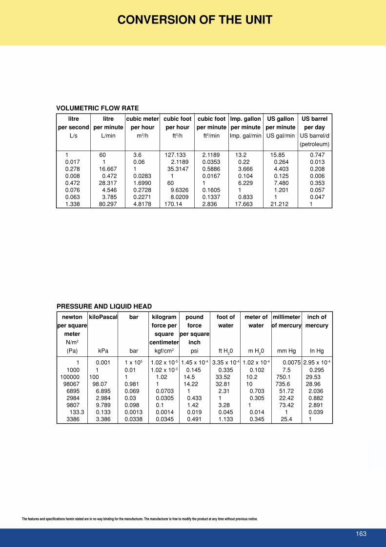
163
The features and specifications herein stated are in no way binding for the manufacturer. The manufacturer is free to modify the product at any time without previous notice.
CONVERSION OF THE UNIT
PRESSURE AND LIQUID HEAD
newton kiloPascal bar kilogram pound foot of meter of millimeter inch ofper square force per force water water of mercury mercury
meter square per squareN/m2 centimeter inch(Pa) kPa bar kgf/cm2 psi ft H20 m H20 mm Hg In Hg
1 0.001 1 x 10⁵ 1.02 x 10⁻⁵ 1.45 x 10⁻⁴ 3.35 x 10⁻⁴ 1.02 x 10⁻⁴ 0.0075 2.95 x 10⁻⁴
1000 1 0.01 1.02 x 10⁻² 0.145 0.335 0.102 7.5 0.295100000 100 1 1.02 14.5 33.52 10.2 750.1 29.53
98067 98.07 0.981 1 14.22 32.81 10 735.6 28.966895 6.895 0.069 0.0703 1 2.31 0.703 51.72 2.0362984 2.984 0.03 0.0305 0.433 1 0.305 22.42 0.8829807 9.789 0.098 0.1 1.42 3.28 1 73.42 2.891133.3 0.133 0.0013 0.0014 0.019 0.045 0.014 1 0.039
3386 3.386 0.0338 0.0345 0.491 1.133 0.345 25.4 1
VOLUMETRIC FLOW RATE
litre litre cubic meter cubic foot cubic foot Imp. gallon US gallon US barrelper second per minute per hour per hour per minute per minute per minute per day
L/s L/min m3/h ft3/h ft3/min Imp. gal/min US gal/min US barrel/d(petroleum)
1 60 3.6 127.133 2.1189 13.2 15.85 0.7470.017 1 0.06 2.1189 0.0353 0.22 0.264 0.0130.278 16.667 1 35.3147 0.5886 3.666 4.403 0.2080.008 0.472 0.0283 1 0.0167 0.104 0.125 0.0060.472 28.317 1.6990 60 1 6.229 7.480 0.3530.076 4.546 0.2728 9.6326 0.1605 1 1.201 0.0570.063 3.785 0.2271 8.0209 0.1337 0.833 1 0.0471.338 80.297 4.8178 170.14 2.836 17.663 21.212 1

164

![WANG ET AL: TACKLING THE UNANNOTATED: SCENE ...2 WANG ET AL: TACKLING THE UNANNOTATED: SCENE GRAPH GENERATION [16] is introduced to facilitate the advancement in the scene graph generation](https://static.fdocuments.net/doc/165x107/6087c7a9ed66401bf25b097f/wang-et-al-tackling-the-unannotated-scene-2-wang-et-al-tackling-the-unannotated.jpg)