
BELL SYSTEM PRACTICES SECTION 592-013-200 …etler.com/docs/BSP/592/592-013-200_I4.pdfBELL SYSTEM...
8
( ( ( BELL SYSTEM PRACTICES Plant Series SECTION 592-013-200 Issue 4, May 1970 AT&TCo Standard DATA SET 202A INSTALLATION & CONNECTIONS 1. GENERAL 1.01 This section covers installation and connection information concerning Data Set (DS) 202A. This section does not include information concerning business machines used with data sets. 1.02 This section is being reissued to: eCombine the installation information with the connection information formerly in Section 592-013-400, Issue 1 eAdd information on data output signal level (option L, M) eAdd information on power level requirements at the serving central office. Because of extensive revision, change arrows have been omitted. 1.03 The DS 202A should be installed in conformance with existing practices covering installation of station sets. See the section entitled Data Sets, General Installation and Connection Information (590-010-200). 2. INSTALLATION 2.01 The preferred installation locates the data set apart from the business machine equipment on a nearby desk, table stand, or in a Bell System-provided equipment cabinet or rack. 2.02 The DS 202A should be located so that the interface cord supplied by the business machine will not exceed 50 feet in length (to reduce stray capacitance and to conform to EIA standards). 2.03 In order to maintain quality service and to minimize interference from related devices, it is preferable to use data sets on individual lines that do not have extensions. 2.04 The customer must furnish a 3-wire ac outlet to accept a plug with two parallel blades and a U-shaped grounding pin. The outlet must not be under control of a switch. 2.05 To avoid the possibility of data errors due to a potential difference between data set ground and business machine ground, the outlet for the data set power cord should be served from the same ac distribution panel as the business machine. If they are not served from the same panel, a test using the 6A impulse counter should be used to detect the presence of noise potentials. This test procedure is described in Section 592-013-500. If test requirement is not met, data set ground and business machine ground must be bonded together. The method of providing this bond should be in accordance with local instructions. 2.06 To minimize inductive interference to data signals on the telephone (data) line, the line should not be carried in the same run as cable between data set and customer business machine or lines connected to de teletypewriter services. If this condition cannot be met, it will be necessary to run telephone (data) line in type SK (shielded) station wire between data set and cable distribution terminal or building entrance. Ground shield at one end only, preferably the distribution terminal end. 2.07 Verify that the loop and overall facilities have been tested and meet transmission requirements as specified: eSwitched Telephone Network (See Section 314-205-501.) ePrivate Line Service (See Section 314-410-500.) © American Telephone and Telegraph Company, 1970 Printed in U.S.A. Page 1
Transcript of BELL SYSTEM PRACTICES SECTION 592-013-200 …etler.com/docs/BSP/592/592-013-200_I4.pdfBELL SYSTEM...

(
(
(
BELL SYSTEM PRACTICES Plant Series
SECTION 592-013-200 Issue 4, May 1970 AT&TCo Standard
DATA SET 202A
INSTALLATION & CONNECTIONS
1. GENERAL
1.01 This section covers installation and connection information concerning Data Set (DS) 202A.
This section does not include information concerning business machines used with data sets.
1.02 This section is being reissued to:
eCombine the installation information with the connection information formerly in Section 592-013-400, Issue 1
eAdd information on data output signal level (option L, M)
eAdd information on power level requirements at the serving central office.
Because of extensive revision, change arrows have been omitted.
1.03 The DS 202A should be installed in conformance with existing practices covering installation
of station sets. See the section entitled Data Sets, General Installation and Connection Information (590-010-200).
2. INSTALLATION
2.01 The preferred installation locates the data set apart from the business machine equipment
on a nearby desk, table stand, or in a Bell System-provided equipment cabinet or rack.
2.02 The DS 202A should be located so that the interface cord supplied by the business
machine will not exceed 50 feet in length (to reduce stray capacitance and to conform to EIA standards).
2.03 In order to maintain quality service and to minimize interference from related devices,
it is preferable to use data sets on individual lines that do not have extensions.
2.04 The customer must furnish a 3-wire ac outlet to accept a plug with two parallel blades
and a U-shaped grounding pin. The outlet must not be under control of a switch.
2.05 To avoid the possibility of data errors due to a potential difference between data set
ground and business machine ground, the outlet for the data set power cord should be served from the same ac distribution panel as the business machine. If they are not served from the same panel, a test using the 6A impulse counter should be used to detect the presence of noise potentials. This test procedure is described in Section 592-013-500. If test requirement is not met, data set ground and business machine ground must be bonded together.
The method of providing this bond should be in accordance with local instructions.
2.06 To minimize inductive interference to data signals on the telephone (data) line, the line
should not be carried in the same run as cable between data set and customer business machine or lines connected to de teletypewriter services. If this condition cannot be met, it will be necessary to run telephone (data) line in type SK (shielded) station wire between data set and cable distribution terminal or building entrance. Ground shield at one end only, preferably the distribution terminal end.
2.07 Verify that the loop and overall facilities have been tested and meet transmission
requirements as specified:
eSwitched Telephone Network (See Section 314-205-501.)
ePrivate Line Service (See Section 314-410-500.)
© American Telephone and Telegraph Company, 1970 Printed in U.S.A. Page 1

SECTION 592-013-200
2.08 Wiring options and overa ll transmission requirements should be specified on the
service order or circuit layout card.
2.09 For information on installation tests, refer to Section 592-013-500.
2. 10 The data set must meet signal-level requirements which allow the data signal level to be no
greater than -12 dBm at the serving central office.
ft Take proper steps to ensure that the customer is not billed for test calls. Refer to the section entitled Crediting Charges on Test Calls (010-250-001).
3. CONNECTIONS AND OPTION PROCEDURES
To prevent possible damage to electronic components in the data set, do not make power connection until all other connections have been made.
3.01 Figures 1 and 2 show the location of terminal boards and miscellaneous parts in DS 202A.
3.02 The data set covers should be removed and replaced as follows:
e Removal:
{a) Loosen, b ut do not remove, the capt iv e screws located around the base.
(b) Remove rear cover.
(c) Remove front cover.
e Replacement:
(a) Position the front cove r on the data se t without securing its mounting screws. Align
plunger slots and mounting brackets with their mating components .
(b) Position the rear cover on the data set so that the bottom edges of the front and rear
covers are in a lig nm ent and seated firmly on the base pan assemb ly. Tig hte n th e cap tiv e screws located on the sides of the data set.
(c) Tighten the remaining captive screws.
POWER SUPPLY FUSES UNDER COVER
COVER SCREW
POWER CORD
MA CH IN E CONNECTION
Fig. 1-Data Set 202A, Rear View
Page 2

ISS 4, SECTION 592-013-200
)
COVER SCREWS
Fig. 2- Data Set 202A, Front View
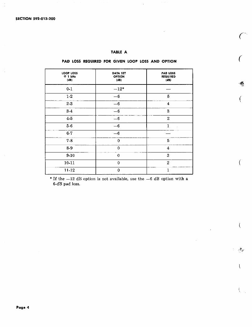
3.03 Table A shows the padding required to ensure that DS 202A conforms to the output
power level requirement for different values of local loop loss.
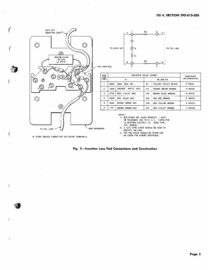
3.04 If a pad is required, it can be constructed locally and installed (see Fig. 3), or it can
be ordered from Western Electric Company by specifying the F-type and pad loss required.
3.05 See Tables E and C for wiring options and connections.
3.06 The spare keys are wired for lA key telephone system operation without a hold
feature. To convert spare keys for lAl operation without a hold feature:
(a) Mo\·e S-Y switchhook lead from 1 to lE on terminal strip TEl.
(b) Move S-ER switchhook lead from 2 to M on terminal strip TEl.
(c) Strap terminals 1 and 2 on terminal strip TEL
3.07 To convert spare pickup keys to nonlocking signal keys, remove screw P-12A892 and
store. Make the following connection changes:
(a) For spare key one, move W-ER lead from M to SG on TEl.
(b) For spare key two, move EK-ER lead from M to SG on TEL
(c) Spare key three is convertible only if the automatic answer circuit is not controlled
by this key. Move Y option strap (connected to terminal 7) from M to SG on TEl.
3.08 Figure 4 shows line connections for the data set and associated telephone circuit.
3.09 Where possible, unused conductors should be secured to spare terminals. Tape and
store unused cord or cable connectors when spare terminals are not available.
Page 3
SECTION 592-013-200
Page 4
TABLE A
PAD LOSS REQUIRED FOR GIVEN LOOP LOSS AND OPTION
LOOP LOSS DATA SET PAD LOSS @1kHz OPTION REQUIRED
(dB) (dB) (dB)
0-1 -12* -
1-2 -6 5
2-3 -6 4
3-4 -6 3
4-5 -6 2
5-6 -6 1
6-7 -6 -
7-8 0 5
8-9 0 4
9-10 0 3
10-11 0 2
11-12 0 1
*If the -12 dB option is not available, use the -6 dB option with a 6-dB pad loss.
(
(
(
(
(
(
(
(
PAD LOSS (DB)
I
2
3
4
5
6
* STORE UNUSED CONDUCTORS ON VACANT TERMINALS
ISS 4, SECTION 592-013-200
TO DATA SET 6 TO TEL LINE
8200
3900
2700
2000
1500
1100
Rl
R R2 R
RESISTOR VALUE (OHMS)
Rl R2 AND R3
GRAY RED RED 47 YELLOW VIOLET BLACK
ORANGE WHITE REO 110 BROWN BROWN BROWN
REO VIOLET RED 160 BROWN BLUE BROWN
REO BLACK REO 220 RED REO BROWN
BROWN GREEN REO 240 REO YELLOW BROWN
BROWN BROWN RED 270 REO VIOLET BROWN
NOTES: I. RESISTORS ARE ALLEN BRADLEY, I WATT,
5~ TOLERANCE (KS- 19151 Ll ). CAPAC! TOR IS WESTERN ELECTRIC CO. 5420 TYPE, IUf, 200VDC.
2. A I 0 I C TYP[ COVER SHOULD BE USED TO PROTECT THE PAD.
3. THE PAD VALUE SHOULD BE STENCILED ON COVER fOR fUTURE REfERENCE.
ORDERING INFORMATION
F-5BIOI
F-58102
F-58103
F-58104
F-58105
F-58106
Fig. 3--lnsertion Loss Pad Connections and Construction
Page 5

SECTION 592-013-200
TABLE B
PROVIDE STRAPS
FEATURE OPTION (SEE NOTE)
QUANTITY
FROM TO
With Pushbutton z DR, TB1 3H,TB1
Automatic 7, TB1 6, TB1 1 Per Answering Without Pushbutton y DR, TB1 6, TB1 Circuit
7, TB1 M,TB1
Output of -12 dBm is required for short L*, M K,TB2 5, TB2 subscriber loop operation. 15, TB2 M,TB2
--Output of -6 dBm is required for normal M 15, TB2 M, TB2 1 Per subscriber loop operation. Circuit
Output of 0 dBm is required for long K 15, TB2 K,TB2 subscriber loop operation.
Equalizer is required for switched net- J H1, TB2 J~, TB2 work application. Hz, TB2 J2, TB2
4, TB2 J:J, TB2 1 Per HH1, TB2 H2, TB2 Circuit
Equalizer is not required on private lines H H2, TB2 H1,TB2 already equalized. 4, TB2 H:l, TB2
Clamp on demodulator output when noise G 9, TB2 G,TB2 protection is required. 1 Per
Clamp removed on demodulator output. Circuit Noise protection is not required. F 9, TB2 F,TB2
900 or less bits/sec operation E 8, TB2 E1,TB2 10, TB2 E2, TB2 1 Per
--1200 bits/sec operation D 8, TB2 D~, TB2 Circuit
10, TB2 D2, TB2
9000 Termination Q 1, TB2 3, TB2 1 Per --
6000 Termination N 1, TB2 2, TB2 Circuit
Note: In early model sets, leads listed in the FROM column were permanently connected. Later model set straps have spade tips on both ends.
* The L option is available only when the set is stamped with the code J1D202A or 202A1 with series D or 2, respectively.
Page 6
(
• I
i

ISS 4, SECTION 592-013-200
( TABLE C
( FEATURE ON INTERFACE TO CUSTOMER
No remote release (Customer Contact closure from 20 to 21 provides ready. Contact open holds permanent short circuit will not allow automatic answer. from 19 to 20 on interface lead.)
Ready and remote release com- Contact closure from 19 to 20 provides ready. Contact open bined (Customer holds perma- will not allow automatic answer. nent short circuit from 20 to 21
Contact open during or after data transmission provides re-on interface lead.) mote release.
Ready and remote release inde- Contact closure from 20 to 21 provides ready. Contact open pendent. will not allow automatic answer.
Contact open from 19 to 20 gives remote release. Contact 19 to 20 normally closed during data transmission.
Page 7

SECTION 592-013-200
TBI
-(;IR
~IT
01B
.n.IH
DATA SET
TB3
ll~~ ~ ~--r-~et------------------------------~1---------~-{~~ZR
f@lj _,.,. 2T
Page 8 8 Pages
-----ir~,~i-- * * ~ :: ~~{ ~
~3R ~~~
83T
I
* TAPED AND STORED AT TBI IN ALL SETS EXCEPT LIST B.
* * WIRED TO S2 AND S3 AT TBI AND TO NO.2 MAKE CONTACT OF C RELAY ON ALL SETS MANUFACTURED AS LIST B.
Fig. 4--Data Set 202A, Connections
(
(