Bell & Gossett Circulators and Hydronic Specialties …€¦ · Bell & Gossett Circulators and...
16
Bell & Gossett Circulators and Hydronic Specialties for Heating and Potable Water Systems Bulletin A-50K Bell & Gossett
Transcript of Bell & Gossett Circulators and Hydronic Specialties …€¦ · Bell & Gossett Circulators and...
Bell & Gossett Circulators and Hydronic
Specialties for Heating andPotable Water Systems
Bulletin A-50K
Bell & Gossett
2
Dimensions & Weights
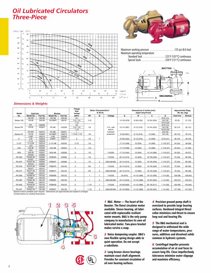
Maximum working pressure . . . . . . . . . . . . . . . . . . .125 psi (8.6 bar)Maximum operating temperature
Standard Seal . . . . . . . . . . . . . . . . . 225°F (107°C) continuousSpecial Seals . . . . . . . . . . . . . . . . . . 250°F (121°C) continuous
1 B&G Motor — The heart of theBooster. The finest circulator motoravailable. Sleeve bearing, oil lubri-cated with replaceable resilientmotor mounts. B&G is the only pumpcompany to manufacture its own oillubricated motor. Two-piece bracketmakes service a snap.
2 Noise dampening coupler. B&G’sown flexible spring design adds toquiet operation. Do not accept a substitute.
3 Long bronze sleeve bearingsmaintain exact shaft alignment.Provides for constant circulation ofoil over bearing surfaces.
4 Precision ground pump shaft isoversized to provide large bearingsurfaces. Hardened integral thrustcollar minimizes end-thrust to ensurelong seal and bearing life.
5 The B&G mechanical seal isdesigned to withstand the widerange of water temperatures, pres-sures, additives and dissolved solidscommon in hydronic systems.
6 Centrifugal impeller preventsaccumulation of air at seal faces toassure long life. Close impeller/bodytolerances minimize water slippageand maximize efficiency.
PD40PD38
PD37
PD35
HD3
HV
2”
2-1/2” & LD3
PR
SER100
Oil Lubricated Circulators Three-Piece
Oil Lubricated CirculatorsCompact Design/Series LR
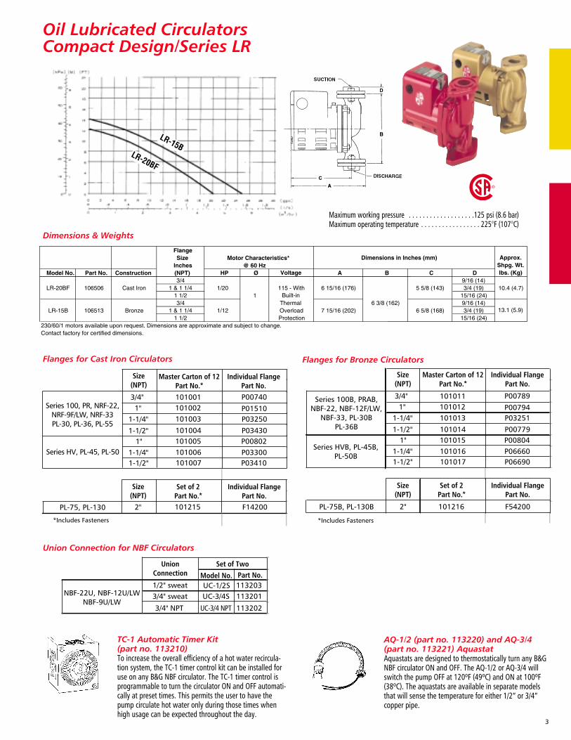
Dimensions & Weights
Maximum working pressure . . . . . . . . . . . . . . . . . . .125 psi (8.6 bar)Maximum operating temperature . . . . . . . . . . . . . . . . . 225°F (107°C)
LR-20BF
LR-15B
TC-1 Automatic Timer Kit (part no. 113210)To increase the overall efficiency of a hot water recircula-tion system, the TC-1 timer control kit can be installed foruse on any B&G NBF circulator. The TC-1 timer control isprogrammable to turn the circulator ON and OFF automati-cally at preset times. This permits the user to have thepump circulate hot water only during those times whenhigh usage can be expected throughout the day.
AQ-1/2 (part no. 113220) and AQ-3/4(part no. 113221) Aquastat Aquastats are designed to thermostatically turn any B&GNBF circulator ON and OFF. The AQ-1/2 or AQ-3/4 willswitch the pump OFF at 120ºF (49ºC) and ON at 100ºF(38ºC). The aquastats are available in separate modelsthat will sense the temperature for either 1/2” or 3/4”copper pipe.
Master Carton of 12Part No.*
Individual FlangePart No.
Size(NPT)
Set of 2Part No.*
Individual FlangePart No.
UnionConnection
Set of TwoPart No.
PL-75, PL-130
*Includes Fasteners
2" 101215 F14200
1132033/4" sweatNBF-22U, NBF-12U/LW
NBF-9U/LW
1/2" sweat
3/4" NPT
113201
113202
UC-1/2SUC-3/4S
UC-3/4 NPT
Model No.
P03410P03300P00802P03430
P03250P01510
P00740
101007101006101005101004
101003101002101001
Size(NPT)
1-1/2"1-1/4"
1-1/4"
1-1/2"1"
1"3/4"
Series 100, PR, NRF-22,NRF-9F/LW, NRF-33PL-30, PL-36, PL-55
Series HV, PL-45, PL-50
Size(NPT)
Master Carton of 12Part No.*
Individual FlangePart No.
Size(NPT)
Set of 2Part No.*
Individual FlangePart No.
Series 100B, PRAB,NBF-22, NBF-12F/LW,
NBF-33, PL-30BPL-36B
Series HVB, PL-45B,PL-50B
PL-75B, PL-130B
*Includes Fasteners
2" 101216 F54200
101017101016101015101014
P06690P06660P00804P00779
P03251P00794
P00789
101013101012101011
1-1/2"1-1/4"
1-1/4"
1-1/2"1"
1"3/4"
3
Union Connection for NBF Circulators
Flanges for Cast Iron Circulators Flanges for Bronze Circulators
4
Maintenance-Free CirculatorsCast Iron Wet Rotor/NRF
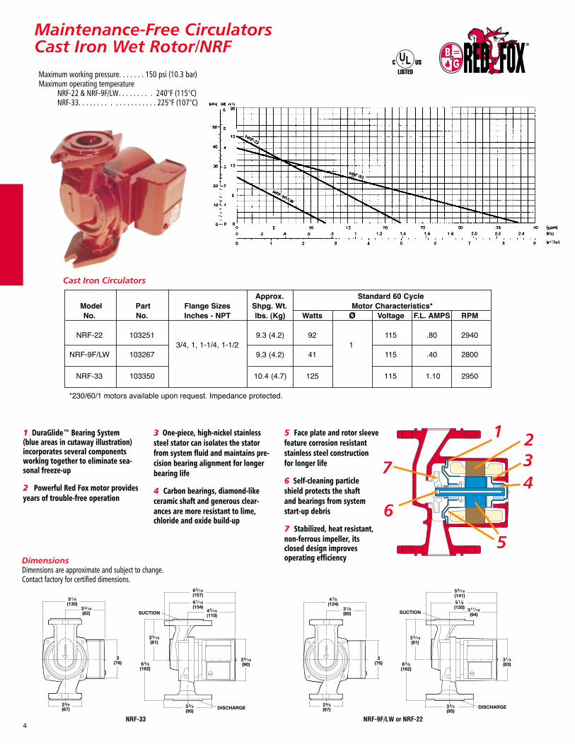
Cast Iron Circulators
1 DuraGlide™ Bearing System (blue areas in cutaway illustration)incorporates several componentsworking together to eliminate sea-sonal freeze-up
2 Powerful Red Fox motor providesyears of trouble-free operation
3 One-piece, high-nickel stainlesssteel stator can isolates the statorfrom system fluid and maintains pre-cision bearing alignment for longerbearing life
4 Carbon bearings, diamond-likeceramic shaft and generous clear-ances are more resistant to lime, chloride and oxide build-up
5 Face plate and rotor sleeve feature corrosion resistant stainless steel constructionfor longer life
6 Self-cleaning particleshield protects the shaft and bearings from systemstart-up debris
7 Stabilized, heat resistant, non-ferrous impeller, its closed design improves operating efficiency
Maximum working pressure. . . . . . . 150 psi (10.3 bar)Maximum operating temperature
NRF-22 & NRF-9F/LW. . . . . . . . . 240°F (115°C)NRF-33. . . . . . . . . . . . . . . . . . . . 225°F (107°C)
NRF-9F/LW or NRF-22 NRF-33
DimensionsDimensions are approximate and subject to change.Contact factory for certified dimensions.
51⁄8(130)
33⁄16(82)
25⁄8(67)
3(76)
SUCTION
DISCHARGE
33⁄16(81)
63⁄8(162)
39⁄16(90)
33⁄4(95)
63⁄16(157)
61⁄16(154)
45⁄16(110)
47⁄8(124)
31⁄8(80)
25⁄8(67)
3(76)
SUCTION
59⁄16(141)
DISCHARGE
311⁄16(94)
33⁄16(81)
63⁄8(162)
31⁄4(83)
33⁄4(95)
51⁄8(130)
1 234
5
6
7
5
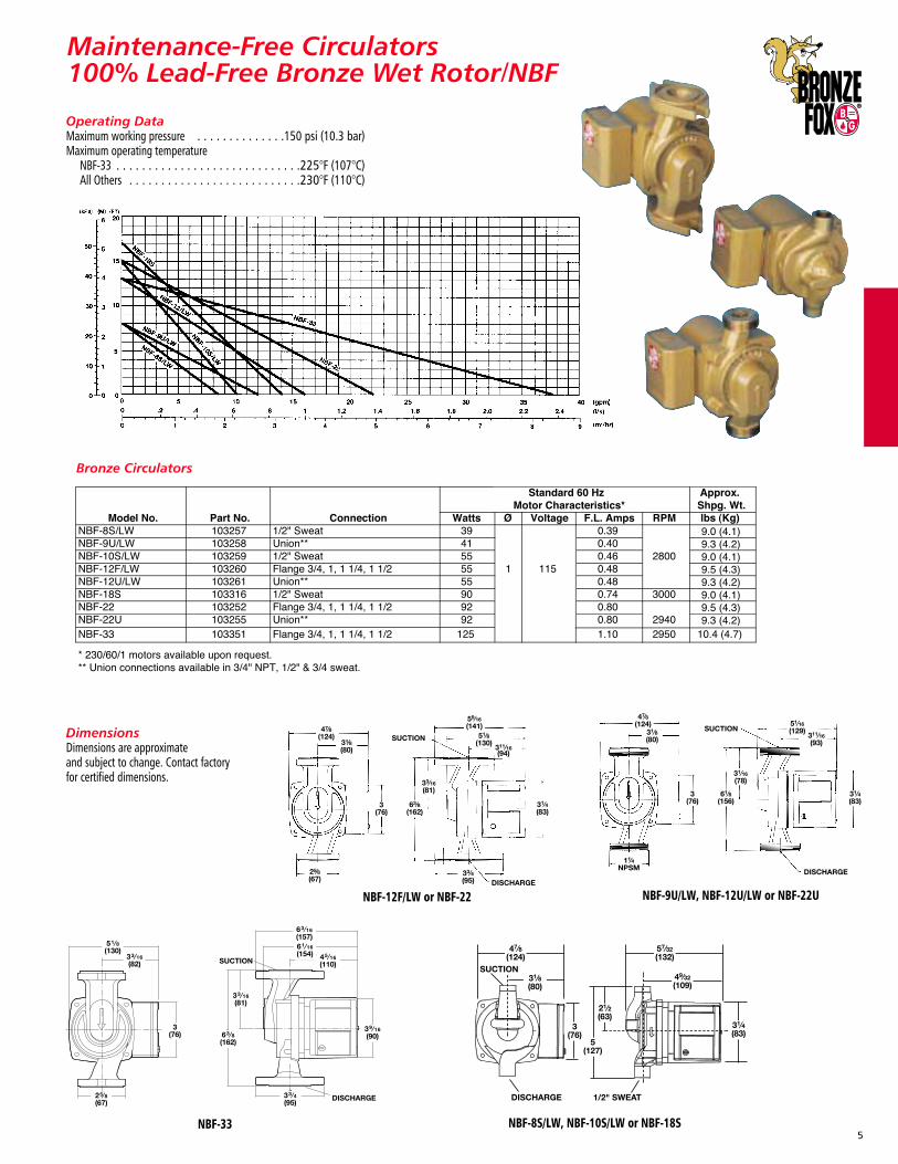
Maintenance-Free Circulators100% Lead-Free Bronze Wet Rotor/NBF
Bronze Circulators
Operating DataMaximum working pressure . . . . . . . . . . . . . .150 psi (10.3 bar)Maximum operating temperature
NBF-33 . . . . . . . . . . . . . . . . . . . . . . . . . . . . .225°F (107°C)All Others . . . . . . . . . . . . . . . . . . . . . . . . . . .230°F (110°C)
DimensionsDimensions are approximate and subject to change. Contact factory for certified dimensions.
NBF-12F/LW or NBF-22 NBF-9U/LW, NBF-12U/LW or NBF-22U
NBF-8S/LW, NBF-10S/LW or NBF-18S
DISCHARGE
SUCTION
11⁄4NPSM
47⁄8(124)
31⁄8(80)
3(76)
51⁄16(129)
311⁄16(93)
31⁄4(83)
61⁄8(156)
31⁄16(78)
47⁄8(124)
DISCHARGE
SUCTION31⁄8(80)
3(76)
25⁄8(67)
63⁄8(162)
33⁄16(81)
59⁄16(141)
51⁄8(130)
311⁄16(94)
31⁄4(83)
33⁄4(95)
NBF-33
51⁄8(130)
33⁄16(82)
25⁄8(67)
3(76)
SUCTION
DISCHARGE
33⁄16(81)
63⁄8(162)
39⁄16(90)
33⁄4(95)
63⁄16(157)61⁄16(154) 45⁄16
(110)
Maintenance-Free Circulators
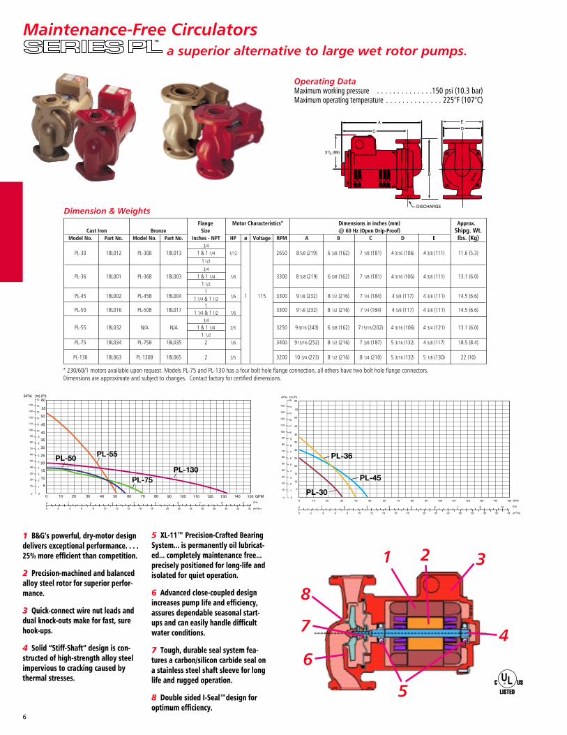
1 B&G’s powerful, dry-motor designdelivers exceptional performance. . . .25% more efficient than competition.
2 Precision-machined and balancedalloy steel rotor for superior perfor-mance.
3 Quick-connect wire nut leads anddual knock-outs make for fast, surehook-ups.
4 Solid “Stiff-Shaft” design is con-structed of high-strength alloy steelimpervious to cracking caused bythermal stresses.
5 XL-11™ Precision-Crafted BearingSystem... is permanently oil lubricat-ed... completely maintenance free...precisely positioned for long-life andisolated for quiet operation.
6 Advanced close-coupled designincreases pump life and efficiency,assures dependable seasonal start-ups and can easily handle difficultwater conditions.
7 Tough, durable seal system fea-tures a carbon/silicon carbide seal ona stainless steel shaft sleeve for longlife and rugged operation.
8 Double sided I-Seal™design foroptimum efficiency.
1 2 3
4
5
6
7
8
Dimension & Weights
* 230/60/1 motors available upon request. Models PL-75 and PL-130 has a four bolt hole flange connection, all others have two bolt hole flange connectors. Dimensions are approximate and subject to changes. Contact factory for certified dimensions.
Flange Motor Characteristics* Dimensions in inches (mm) Approx.Cast Iron Bronze Size @ 60 Hz (Open Drip-Proof) Shipg. Wt.
Model No. Part No. Model No. Part No. Inches - NPT HP ø Voltage RPM A B C D E Ibs. (Kg)3/4
PL-30 1BL012 PL-30B 1BL013 1 & 1 1/4 1/12 2650 8 5/8 (219) 6 3/8 (162) 7 1/8 (181) 4 3/16 (106) 4 3/8 (111) 11.6 (5.3)11/2
3/4
PL-36 1BL001 PL-36B 1BL003 1 & 1 1/4 1/6 3300 8 5/8 (219) 6 3/8 (162) 7 1/8 (181) 4 3/16 (106) 4 3/8 (111) 13.1 (6.0)1 1/2
1PL-45 1BL002 PL-45B 1BL004 1 1/4 & 1 1/2 1/6 1 115 3300 91/8 (232) 8 1/2 (216) 7 1/4 (184) 4 5/8 (117) 4 3/8 (111) 14.5 (6.6)
1PL-50 1BL016 PL-50B 1BL017 1 1/4 & 1 1/2 1/6 3300 9 1/8 (232) 8 1/2 (216) 7 1/4 (184) 4 5/8 (117) 4 3/8 (111) 14.5 (6.6)
3/4
PL-55 1BL032 N/A N/A 1 & 1 1/4 2/5 3250 9 9/16 (243) 6 3/8 (162) 715/16 (202) 4 3/16 (106) 4 3/4 (121) 13.1 (6.0)1 1/2
PL-75 1BL034 PL-75B 1BL035 2 1/6 3400 915/16 (252) 8 1/2 (216) 7 3/8 (187) 5 3/16 (132) 4 5/8 (117) 18.5 (8.4)
PL-130 1BL063 PL-130B 1BL065 2 2/5 3200 10 3/4 (273) 8 1/2 (216) 8 1/4 (210) 5 3/16 (132) 5 1/8 (130) 22 (10)
6
Operating DataMaximum working pressure . . . . . . . . . . . . . .150 psi (10.3 bar)Maximum operating temperature . . . . . . . . . . . . . . 225°F (107°C)
a superior alternative to large wet rotor pumps.
7
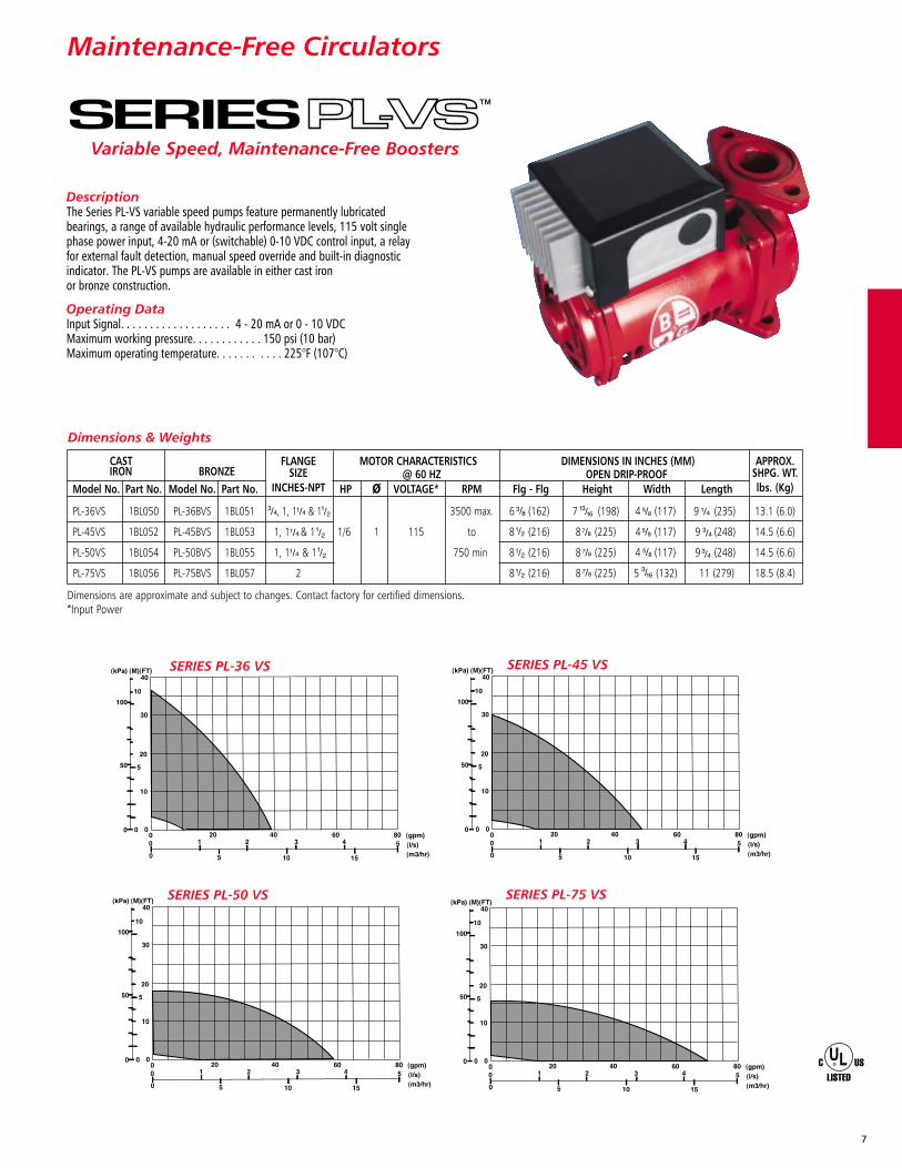
SERIES PL-36 VS
SERIES PL-75 VS
SERIES PL-45 VS
SERIES PL-50 VS
DescriptionThe Series PL-VS variable speed pumps feature permanently lubricatedbearings, a range of available hydraulic performance levels, 115 volt singlephase power input, 4-20 mA or (switchable) 0-10 VDC control input, a relayfor external fault detection, manual speed override and built-in diagnosticindicator. The PL-VS pumps are available in either cast iron or bronze construction.
Operating DataInput Signal. . . . . . . . . . . . . . . . . . . 4 - 20 mA or 0 - 10 VDCMaximum working pressure. . . . . . . . . . . . 150 psi (10 bar)Maximum operating temperature. . . . . . . . . . . 225°F (107°C)
Maintenance-Free Circulators
Variable Speed, Maintenance-Free Boosters
Dimensions & Weights
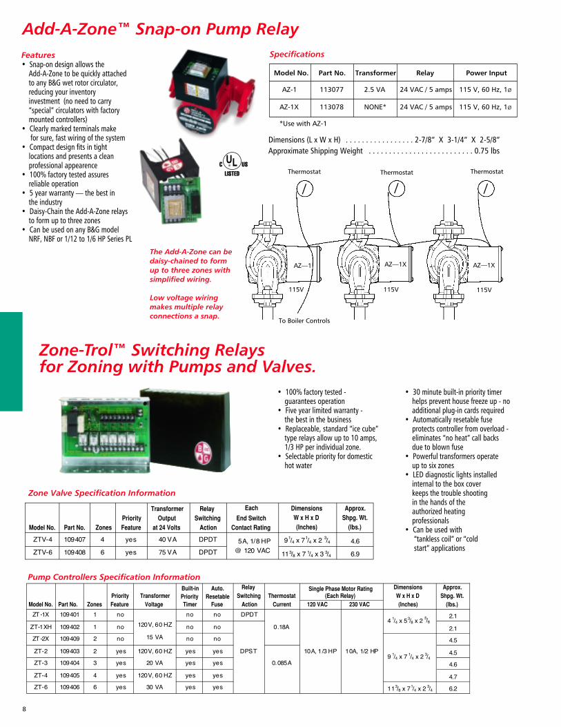
Add-A-Zone™ Snap-on Pump Relay
Pump Controllers Specification Information
Zone Valve Specification Information
• 30 minute built-in priority timer helps prevent house freeze up - no additional plug-in cards required
• Automatically resetable fuse protects controller from overload - eliminates “no heat” call backs due to blown fuse
• Powerful transformers operate up to six zones
• LED diagnostic lights installed internal to the box coverkeeps the trouble shootingin the hands of the authorized heating professionals
• Can be used with“tankless coil” or “cold start” applications
Features• Snap-on design allows the
Add-A-Zone to be quickly attached to any B&G wet rotor circulator, reducing your inventory investment (no need to carry “special” circulators with factory mounted controllers)
• Clearly marked terminals make for sure, fast wiring of the system
• Compact design fits in tight locations and presents a clean professional appearence
• 100% factory tested assures reliable operation
• 5 year warranty — the best in the industry
• Daisy-Chain the Add-A-Zone relays to form up to three zones
• Can be used on any B&G model NRF, NBF or 1/12 to 1/6 HP Series PL
The Add-A-Zone can bedaisy-chained to form up to three zones with simplified wiring.
Low voltage wiringmakes multiple relayconnections a snap.
/ /ThermostatThermostat Thermostat
To Boiler Controls
AZ—1
/
AZ—1XAZ—1X
115V 115V 115V
8
Specifications
Dimensions (L x W x H) . . . . . . . . . . . . . . . . . 2-7/8” X 3-1/4” X 2-5/8”Approximate Shipping Weight . . . . . . . . . . . . . . . . . . . . . . . . . . 0.75 lbs
• 100% factory tested - guarantees operation
• Five year limited warranty - the best in the business
• Replaceable, standard “ice cube”type relays allow up to 10 amps, 1/3 HP per individual zone.
• Selectable priority for domestic hot water
Zone-Trol™ Switching Relays for Zoning with Pumps and Valves.
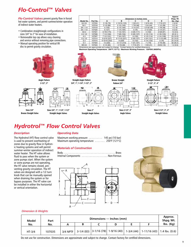
Flo-Control™ Valves
Hydrotrol™ Flow Control Valves
D
B
CA
E
Flo-Control Valves prevent gravity flow in forcedhot water systems, and permit summer/winter operationof indirect water heaters.
• Combination straight/angle configurations insizes 3/4” to 2” for ease of installation.
• Removeable top cap allows easy cleaning and service without removing pipe connections.
• Manual operating position for vertical liftdisc to permit gravity circulation.
Angle Pattern2-1/2”, 3”
Straight-Angle Pattern3/4”, 1”, 1-1/4”, 1-1/2”, 2”
Straight Pattern2-1/2”, 3”, 4”
Bronze StraightPattern 3/4”
Sizes 3/4”Bronze Straight Valve
9
A
A
A
B
C D
E
F
Description
The Hydrotrol (HT) flow control valveis used to prevent overheating ofzones due to gravity flow in hydron-ic heating systems and will permitsummer-winter operation of indirectwater heater. The HT valve allowsfluid to pass when the system orzone pumps start. When the systemor zone pumps are not operating,the HT valve remains closed, pre-venting gravity circulation. The HTvalves are designed with a 1/2 turnknob that can be manually openedwhen draining the system or forbypass purposes. The HT valve canbe installed in either the horizontalor vertical orientation.
Operating Data
Maximum working pressure . . . . . . . . . . 145 psi (10 bar)Maximum operating temperature . . . . . . . 250°F (121°C)
Materials of Construction
Body . . . . . . . . . . . . . . . . . . . . . . . . . . . . . . . . . . . . . . BrassInternal Components . . . . . . . . . . . . . . . . . . . Non-Ferrous
Dimension & Weights
Sizes 3/4”, 1”, 1-1/4”, 1-1/2”Straight Angle Valves
Sizes 2-1/2”, 3”, 4”Straight Valves
Sizes 2”Straight Angle Valves
Sizes 2-1/2”, 3”Angle Valves
10
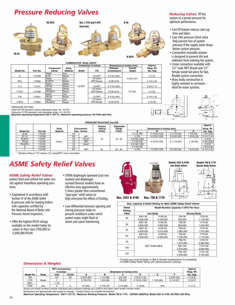
ASME Safety Relief Valves
Dimensions & Weights
ASME Safety Relief Valvesprotect fired and unfired hot water ves-sels against hazardous operating pres-sures.
• Engineered in accordance withSection IV of the ASME boiler & pressure code for heating boilerswith capacities certified bythe National Board of Boiler andPressure Vessel Inspectors.
• Offer the highest BTUH ratings available on the market today forvalves in their class (790,000 to5,999,000 BTUH)
• EPDM diaphragm operated (cast ironmodels) and diaphragmassisted (bronze models) have aneffective area approximately 5 times greater than conventional“pop-type” relief valves tohelp overcome the effects of fouling.
• Low differential between opening andclosing pressures helps toprevent conditions under which system water might flash tosteam and cause hammering.
Models 3301 & 4100Iron Body Valves
Nos. 3301 & 4100 Nos. 790 & 1170
Models 790 & 1170Bronze Body Valves
Pressure Reducing Valves Reducing Valves fill the system to a preset pressure for optimum performance.
• Fast fill feature reduces start-uptime and labor.
• Low inlet pressure check valve help prevent loss of systempressure if the supply water dropsbelow system pressure.
• Convenient cleanable strainer is designed to prevent dirt andsediment from entering the system.
• Union connection available with 1/2” male NPT thread and 1/2”female sweat tail-piece for fast, flexible system connection.
• Brass body construction ishighly resistant to corrosion --ideal for water systems.
Nos. F-3TU and F-8TUDual Unit
FB-38
FB-38TU B-38
B-38TU
11
Copper Red Ring Monoflo® FittingsDimensions & WeightsCopper Red Ring Monoflo Fittings let you use a single pipe
to serve as both supply and return main.
• Connect risers to the main, assuringproper diversion of water to eachheating unit regardless of type and its position in the system.
• Recommended for most installations including cast ironnon-ferrous baseboards, free-standing radiation or convectors.
• Only one fitting is needed for most installations for adequate diversionfor upfeed radiation. For most applications, a second fitting can beused if higher resistance is required.
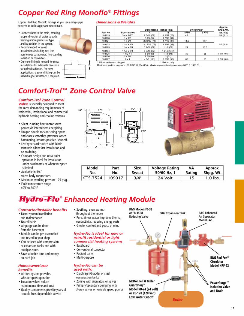
Enhanced Heating Module
Boiler
Contractor/installer benefits• Faster system installation
and maintenance• No callbacks• Air purge can be done
from the basement• Module can be pre-assembled
and tested in your shop• Can be used with compression
or expansion tanks and withmultiple zones
• Save valuable time and moneyon each job
Homeowner/user benefits• Air-free system provides
whisper-quiet operation• Isolation valves reduce
maintenance time and cost• Quality components provide years of
trouble-free, dependable service
• Soothing, even warmththroughout the house
• Pure, airless water improves thermalconductivity, reducing energy costs
• Greater comfort and peace of mind
Hydro-Flo is ideal for new orretrofit residential or lightcommercial heating systems• Baseboard• Conventional convector• Radiant panel• Multi-purpose
Hydro-Flo can be used with:• Diaphragm/bladder or steel
compression tanks• Zoning with circulators or valves• Primary/secondary pumping with
3-way valves or variable speed pumps
B&G Models FB-38or FB-38TUReducing Valve
B&G Expansion Tank B&G EnhancedAIr SeparatorModel EAS
McDonnell & MillerGuardDog™ Model RB-24 (24 volt) or RB-120 (120 volt) Low Water Cut-off
B&G Red Fox®
CirculatorModel NRF-22
PowerPurge™Isolation Valveand Drain
Comfort-Trol™ Zone Control ValveComfort-Trol Zone ControlValve is specially designed to meetthe most demanding requirements ofresidential, institutional and commercialhydronic heating and cooling systems.
• Silent -running heat motor savespower via intermittent energizing.
• Unique double torsion spring opens and closes smoothly, prevents water hammering, assures positive shut-off.
• Leaf-type stack switch with blade terminals allow fast installation andno soldering.
• Compact design and ultra-quiet operation is ideal for installation under baseboards or wherever spaceis limited.
• Available in 3/4” sweat body connections.
• Maximum working pressure 125 psig.• Fluid temperature range
40°F to 240°F
Inline Air SeparatorDescriptionThe B&G In-Line Air Separator isspecificaly designed to efficientlyseparate air from circulating water inhydronic heating and cooling sys-tems to assure quiet operation.
Operating DataMaximum working pressure . . . . . . . . . . . . . . . .175 psig (1,207 kPa)Maximum operating temperature . . . . . . . . . . . . . . . . . 300°F (149°C)
ConstructionOne Piece Cast Iron
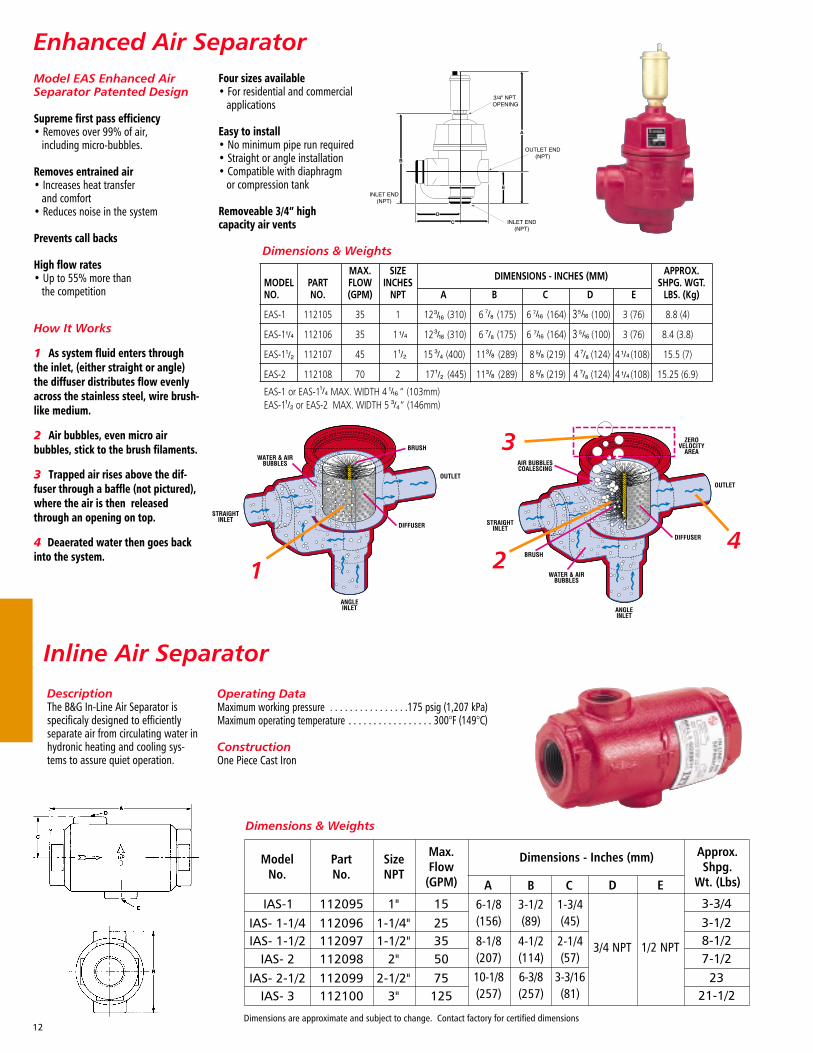
Enhanced Air Separator
1 2
3
4
Model EAS Enhanced AirSeparator Patented Design
Supreme first pass efficiency• Removes over 99% of air,
including micro-bubbles.
Removes entrained air• Increases heat transfer
and comfort• Reduces noise in the system
Prevents call backs
High flow rates• Up to 55% more than
the competition
Dimensions & Weights
Four sizes available• For residential and commercial
applications
Easy to install• No minimum pipe run required• Straight or angle installation• Compatible with diaphragm
or compression tank
Removeable 3/4” high capacity air vents
12
How It Works
1 As system fluid enters throughthe inlet, (either straight or angle)the diffuser distributes flow evenlyacross the stainless steel, wire brush-like medium.
2 Air bubbles, even micro air bubbles, stick to the brush filaments.
3 Trapped air rises above the dif-fuser through a baffle (not pictured),where the air is then releasedthrough an opening on top.
4 Deaerated water then goes backinto the system.
Dimensions & Weights
.
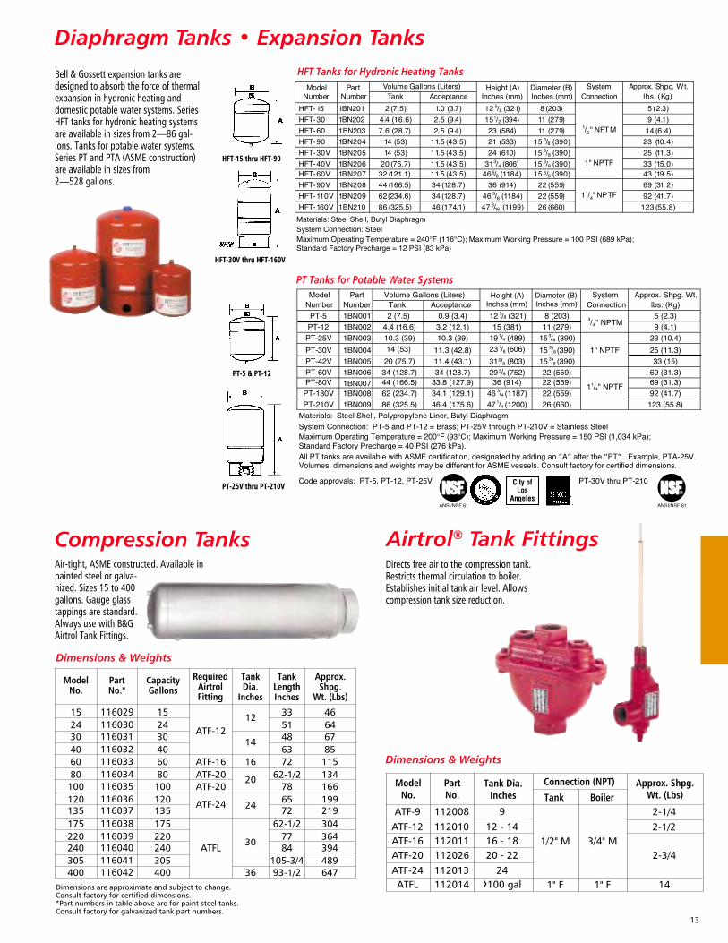
Diaphragm Tanks • Expansion Tanks
Compression Tanks Airtrol® Tank FittingsDirects free air to the compression tank.Restricts thermal circulation to boiler.Establishes initial tank air level. Allowscompression tank size reduction.
Air-tight, ASME constructed. Available inpainted steel or galva-nized. Sizes 15 to 400gallons. Gauge glasstappings are standard.Always use with B&GAirtrol Tank Fittings.
Bell & Gossett expansion tanks aredesigned to absorb the force of thermalexpansion in hydronic heating anddomestic potable water systems. SeriesHFT tanks for hydronic heating systemsare available in sizes from 2—86 gal-lons. Tanks for potable water systems,Series PT and PTA (ASME construction)are available in sizes from 2—528 gallons.
City of Los
Angeles
HFT-15 thru HFT-90
HFT-30V thru HFT-160V
PT-5 & PT-12
PT-25V thru PT-210V
HFT Tanks for Hydronic Heating Tanks
PT Tanks for Potable Water Systems
13
Dimensions & Weights
Dimensions & Weights
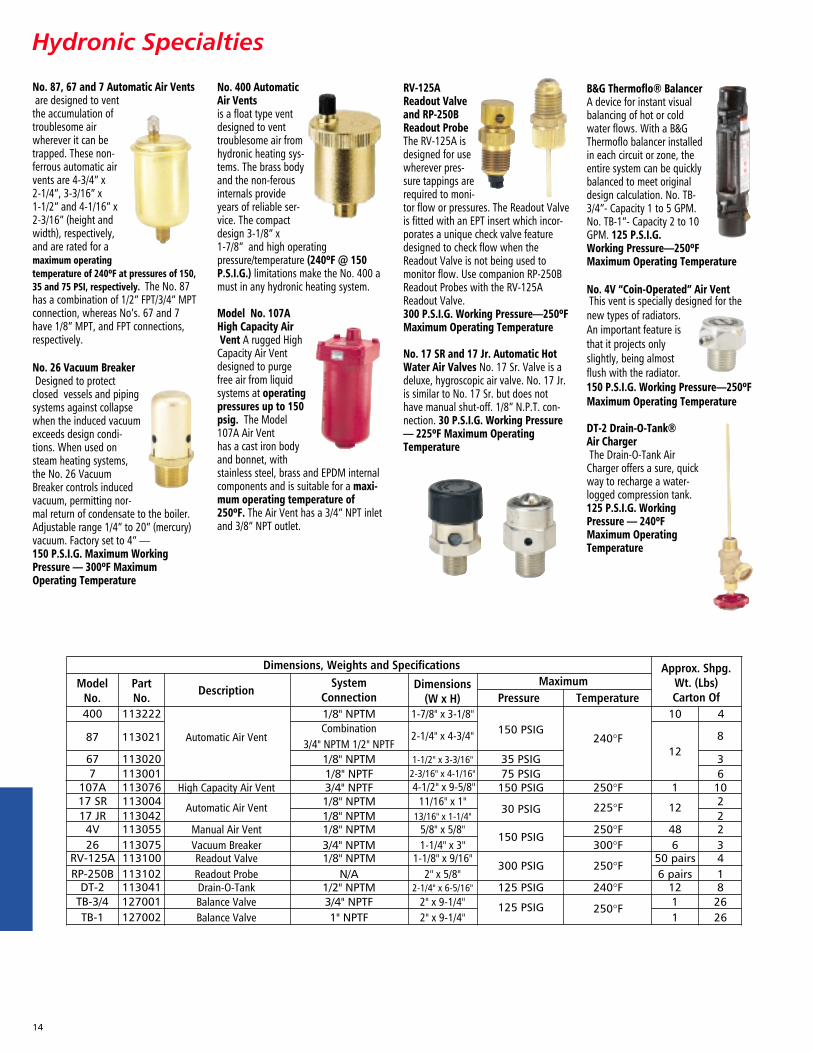
Hydronic Specialties
No. 87, 67 and 7 Automatic Air Ventsare designed to ventthe accumulation oftroublesome airwherever it can betrapped. These non-ferrous automatic airvents are 4-3/4” x 2-1/4”, 3-3/16” x 1-1/2” and 4-1/16” x2-3/16” (height andwidth), respectively,and are rated for amaximum operatingtemperature of 240ºF at pressures of 150,35 and 75 PSI, respectively. The No. 87has a combination of 1/2” FPT/3/4” MPTconnection, whereas No’s. 67 and 7have 1/8” MPT, and FPT connections,respectively.
No. 26 Vacuum BreakerDesigned to protectclosed vessels and pipingsystems against collapsewhen the induced vacuumexceeds design condi-tions. When used onsteam heating systems,the No. 26 VacuumBreaker controls inducedvacuum, permitting nor-mal return of condensate to the boiler.Adjustable range 1/4” to 20” (mercury)vacuum. Factory set to 4” —150 P.S.I.G. Maximum WorkingPressure — 300ºF MaximumOperating Temperature
No. 400 AutomaticAir Ventsis a float type ventdesigned to venttroublesome air fromhydronic heating sys-tems. The brass bodyand the non-ferousinternals provideyears of reliable ser-vice. The compactdesign 3-1/8” x 1-7/8” and high operatingpressure/temperature (240ºF @ 150P.S.I.G.) limitations make the No. 400 amust in any hydronic heating system.
Model No. 107AHigh Capacity AirVent A rugged High
Capacity Air Ventdesigned to purgefree air from liquidsystems at operatingpressures up to 150psig. The Model107A Air Vent has a cast iron bodyand bonnet, withstainless steel, brass and EPDM internalcomponents and is suitable for a maxi-mum operating temperature of250ºF. The Air Vent has a 3/4” NPT inletand 3/8” NPT outlet.
RV-125AReadout Valveand RP-250BReadout ProbeThe RV-125A isdesigned for usewherever pres-sure tappings arerequired to moni-tor flow or pressures. The Readout Valveis fitted with an EPT insert which incor-porates a unique check valve featuredesigned to check flow when theReadout Valve is not being used tomonitor flow. Use companion RP-250BReadout Probes with the RV-125AReadout Valve. 300 P.S.I.G. Working Pressure—250ºFMaximum Operating Temperature
No. 17 SR and 17 Jr. Automatic HotWater Air Valves No. 17 Sr. Valve is adeluxe, hygroscopic air valve. No. 17 Jr.is similar to No. 17 Sr. but does nothave manual shut-off. 1/8” N.P.T. con-nection. 30 P.S.I.G. Working Pressure— 225ºF Maximum OperatingTemperature
B&G Thermoflo® BalancerA device for instant visual balancing of hot or coldwater flows. With a B>hermoflo balancer installedin each circuit or zone, theentire system can be quicklybalanced to meet originaldesign calculation. No. TB-3/4”- Capacity 1 to 5 GPM.No. TB-1”- Capacity 2 to 10GPM. 125 P.S.I.G.Working Pressure—250ºFMaximum Operating Temperature
No. 4V “Coin-Operated” Air VentThis vent is specially designed for thenew types of radiators.An important feature isthat it projects onlyslightly, being almostflush with the radiator.150 P.S.I.G. Working Pressure—250ºFMaximum Operating Temperature
DT-2 Drain-O-Tank® Air ChargerThe Drain-O-Tank AirCharger offers a sure, quickway to recharge a water-logged compression tank. 125 P.S.I.G. WorkingPressure — 240ºFMaximum OperatingTemperature
14
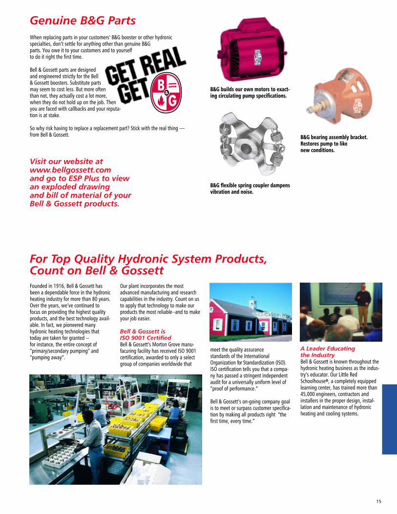
For Top Quality Hydronic System Products,Count on Bell & Gossett
Genuine B&G Parts
Founded in 1916, Bell & Gossett hasbeen a dependable force in the hydronicheating industry for more than 80 years.Over the years, we’ve continued tofocus on providing the highest qualityproducts, and the best technology avail-able. In fact, we pioneered manyhydronic heating technologies thattoday are taken for granted -- for instance, the entire concept of “primary/secondary pumping” and“pumping away”.
When replacing parts in your customers’ B&G booster or other hydronicspecialties, don’t settle for anything other than genuine B&Gparts. You owe it to your customers and to yourselfto do it right the first time.
Bell & Gossett parts are designedand engineered strictly for the Bell& Gossett boosters. Substitute partsmay seem to cost less. But more oftenthan not, they actually cost a lot more,when they do not hold up on the job. Thenyou are faced with callbacks and your reputa-tion is at stake.
So why risk having to replace a replacement part? Stick with the real thing — from Bell & Gossett.
Visit our website at www.bellgossett.com and go to ESP Plus to view an exploded drawing and bill of material of your Bell & Gossett products.
Our plant incorporates the mostadvanced manufacturing and researchcapabilities in the industry. Count on usto apply that technology to make ourproducts the most reliable--and to makeyour job easier.
Bell & Gossett is ISO 9001 CertifiedBell & Gossett’s Morton Grove manu-facuring facility has received ISO 9001certification, awarded to only a selectgroup of companies worldwide that
A Leader Educating the IndustryBell & Gossett is known throughout thehydronic heating business as the indus-try’s educator. Our Little RedSchoolhouse®, a completely equippedlearning center, has trained more than45,000 engineers, contractors andinstallers in the proper design, instal-lation and maintenance of hydronicheating and cooling systems.
B&G builds our own motors to exact-ing circulating pump specifications.
B&G bearing assembly bracket.Restores pump to like new conditions.
B&G flexible spring coupler dampensvibration and noise.
meet the quality assurance standards of the InternationalOrganization for Standardization (ISO).ISO certification tells you that a compa-ny has passed a stringent independentaudit for a universally uniform level of“proof of performance.”
Bell & Gossett’s on-going company goalis to meet or surpass customer specifica-tion by making all products right “thefirst time, every time.”
15
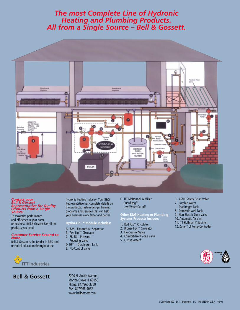
The most Complete Line of Hydronic Heating and Plumbing Products.
All from a Single Source – Bell & Gossett.
Contact your Bell & GossettRepresentative for QualityProducts from a SingleSource.To maximize performance and efficiency in your home or business, Bell & Gossett has all theproducts you need.
Customer Service Second toNone.Bell & Gossett is the Leader in R&D andtechnical education throughout the
hydronic heating industry. Your B&GRepresentative has complete details onthe products, system design, trainingprograms and services that can helpyour business work faster and better.
Hydro-Flo.™ Module Includes:
A. EAS - Ehanced Air SeparatorB. Red Fox™ CirculatorC. FB-38 -- Pressure
Reducing ValveD. HFT— Diaphragm TankE. Flo-Control Valve
F. ITT McDonnell & Miller GuardDog™ Low Water Cut-off
Other B&G Heating or PlumbingSystems Products Include:
1. Red Fox™ Circulator2. Bronze Fox™ Circulator3. Flo-Control Valve4. Comfort-Trol® Zone Valve5. Circuit Setter®
6. ASME Safety Relief Valve7. Potable Water
Diaphragm Tank8. Domestic Well Tank9. Non-Electric Zone Valve10. Automatic Air Vent11. ITT Hoffman Y-Strainer12. Zone-Trol Pump Controller
©Copyright 2001 by ITT Industries, Inc. PRINTED IN U.S.A 05/01
8200 N. Austin Avenue Morton Grove, IL 60053 Phone: 847/966-3700FAX: 847/966-9052www.bellgossett.com
Bell & Gossett