Belarus 1025, 1025.2, 1025.3 Operation manual MTZ
205
BELARUS 1025/1025.2/1025.3 1025 – 0000010OM OPERATION MANUAL The fourth edition, revised and supplemented 2008
description
1025 Series ManualEnglish
Transcript of Belarus 1025, 1025.2, 1025.3 Operation manual MTZ
BELARUS 1025/1025.2/1025.3
1025 – 0000010OM
OPERATION MANUAL
The fourth edition, revised and supplemented
2008
The present operation manual has been compiled by A.G.Sanchuk, engineer of MSDB-MTW, with participation of the leading specialists of Central Special Design Bureau of RUE “Minsk Tractor Works”
Executive Editor — I.N. Uss, Director of the Scientific- Technical Center Chief designer
Managing Editor — O.N. Natalevich, head of Design Bureau
Tractors Belarus 1025/1025.2/1025.3 Operation manual. 4th edition, revised and supplemented.
Operation manual contains brief description and technical characteristics of tractors Belarus 1025/1025.2/1025.3 manufactured by Minsk Tractor Works. Principal rules of machine operation are set forth, data on their adjustments and maintenance are given.
The manual is intended for operators of tractors Belarus.
Due to policy of PA “MTW” aimed at constant update of items being manufactured, design of some assembly units and parts of tractor Belarus may be changed without being shown in the present edition.
Some technical data and figures given in this book may differ from actual ones on your tractor. Dimensions and values of mass are approximate (given for reference). You may obtain detailed information from your dealers of Belarus.
RUE “Minsk Tractor Works”, 2008 All rights reserved. No part of this manual may be reproduced in any form whatsoever without written permit of RUE “Minsk Tractor Works”
FOR THE ATTENTION OF OPERATORS
1. Before starting work thoroughly study the present operation manual and strictly follow all operation and maintenance directions.
2. Be sure to run the tractor in for thirty hours. Put load up to 80% of rated power before the first maintenance M-1 (125 hours).
3. Your tractor is equipped with range-type gear box. It means ranges are shifted by means of toothed-type coupling and gears within each range – by synchronizers.
To shift the range: — Press out the clutch pedal and wait until full tractor stop; — Using range shifting lever smoothly and without jerks engage the required range; — Smoothly release the clutch pedal.
To put in gear: — Press out the clutch pedal; — Smoothly, without sharp jerks move gear shifting lever and hold it pressed until gear is
fully put in; — Smoothly release the clutch pedal.
Put in gears within the range while running only during transport operation on hard surface and dirt roads. During the off-road (ploughed field, peat field, sand soil) tractor travel gear shifting while running IS NOT ALLOWED due to sharp stop of the machine. In this case use earlier selected gear to travel across these legs. Failure to observe these operation directions leads to fast wear of gears’ splines and toothed-type couplings, as well as damage of synchronizers.
ATTENTION! If, with clutch pedal pressed out, ranges and gears are shifted with grinding sound, promptly address the dealer’s center to correct malfunction.
4. Follow directions for switching PTO. With PTO control lever engaged, smoothly, with 2…4 s delay in the middle of travel from the neutral to PTO switching to avoid damage of shaft, reduction gears and PTO driving end.
5. Make adjustment of wheel and parking brakes only on horizontal terrain with diesel shut down and wedges placed at the front and back sides of rear wheels to exclude accidental movement of the tractor.
6. Do not operate the tractor without storage batteries connected to the electrical equipment system and “ground” switch being off with the running engine.
Belarus 1025/1025.2/1025.3 ______________________________________________ Contents 1
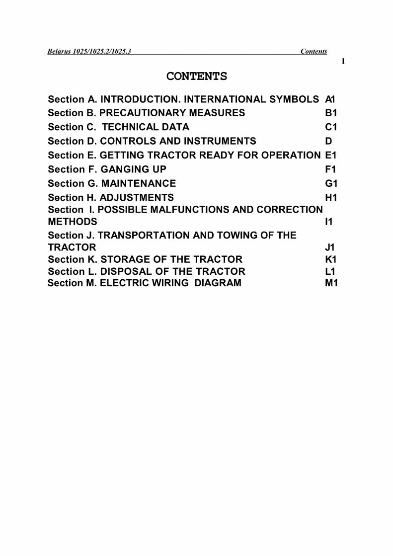
CONTENTS
Section А. INTRODUCTION. INTERNATIONAL SYMBOLS А1
Section B. PRECAUTIONARY MEASURES B1
Section C. TECHNICAL DATA C1
Section D. CONTROLS AND INSTRUMENTS D
Section E. GETTING TRACTOR READY FOR OPERATION E1
Section F. GANGING UP F1
Section G. MAINTENANCE G1
Section H. ADJUSTMENTS H1 Section I. POSSIBLE MALFUNCTIONS AND CORRECTION METHODS I1 Section J. TRANSPORTATION AND TOWING OF THE TRACTOR J1
Section K. STORAGE OF THE TRACTOR K1
Section L. DISPOSAL OF THE TRACTOR L1
Section M. ELECTRIC WIRING DIAGRAM M1
Belarus 1025/1025.2/1025.3 Section А.Introduction А1
Section А. INTRODUCTION
The present operation manual contains major technical data and recommendations on the operation and maintenance of tractors Belarus 1025/1025.2/1025.3.
Tractors Belarus 1025/1025.2/1025.3 are designed for executing various agricultural works with mounted, half-mounted and trailing machines and implements, in transportation, with loading, unloading mechanisms, harvesting complexes and for driving stationary machines.
Tractor Belarus 1025 – is a base model with engine Д-245, rated power of 77 kW (104.6 hp), front drive axle (FDA) of portal type with coned wheel reduction gears, hydraulic mounting system with power regulator and traction-coupling mechanism TCM-1J (cross-piece).
Tractors Belarus 1025.2 and Belarus 1025.3 are modifications of the base model.
Tractor Belarus 1025.2 – with engine Д-245 with rated power of 77 kW (104.6 hp), beam-type FDA with planetary-cylindrical wheel reduction gears, hydraulic mounting system with power regulator and traction-coupling mechanism TCM1J (cross-piece), or hydraulic lift and lift-type TCM with yoke TCM-3V.
Tractors Belarus 1025 and Belarus 1025.2 can be equipped (optionally) with engine Д-245S with rated power of 79 kW (107.3 hp), certified according to the 1st stage of Directive 2000/25 ЕС.
Tractor Belarus 1025.3 – with engine Д-245S2 has rated power of 81 kW (110.0 hp), beam-type FDA with planetary-cylindrical wheel reduction gears, hydraulic mounting system with power regulator and traction-coupling mechanism TCM-1J (cross-piece), or hydraulic lift and lift-type TCM-3 (yoke). Updated design of the cabin and hood. Engine Д-245S2 is certified according to 2nd stage of Directive 2000/25 EC.
ATTENTION! Prolonged and reliable tractor operation is possible only if proper operation and timely maintenance are observed
ATTENTION! Before putting new tractor into operation study the present
operation manual and strictly follow recommendations thereof, to avoid accidents, injures or mutilations.
Note: Reference in the present manual text made to “left-side” or “right-side” are made from the view of the observer standing behind the running tractor.
Note: Due to constant tractor update and improvement of working conditions, changes, not indicated in the present edition, may be introduced to the tractor design.
Re-equipment and alteration of tractor design without approval of the manufacturer are forbidden.
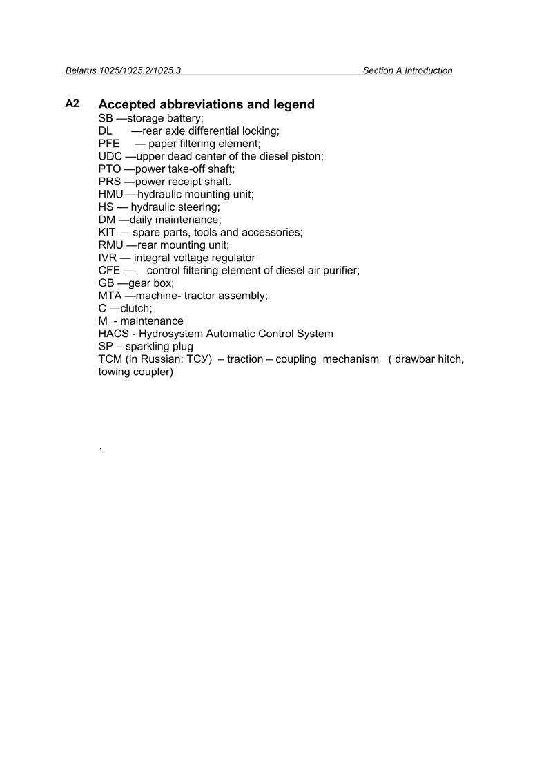
Belarus 1025/1025.2/1025.3 Section A Introduction А2 Accepted abbreviations and legend
SB —storage battery; DL —rear axle differential locking; PFE — paper filtering element; UDC —upper dead center of the diesel piston; PTO —power take-off shaft; PRS —power receipt shaft. HMU —hydraulic mounting unit; HS — hydraulic steering; DM —daily maintenance; KIT — spare parts, tools and accessories; RMU —rear mounting unit; IVR — integral voltage regulator CFE — control filtering element of diesel air purifier; GB —gear box; МТА —machine- tractor assembly; С —clutch; M - maintenance HACS - Hydrosystem Automatic Control System SP – sparkling plug TCM (in Russian: ТСУ) – traction – coupling mechanism ( drawbar hitch, towing coupler) .
Belarus 1025/1025.2/1025.3 section А. IntroductionА3
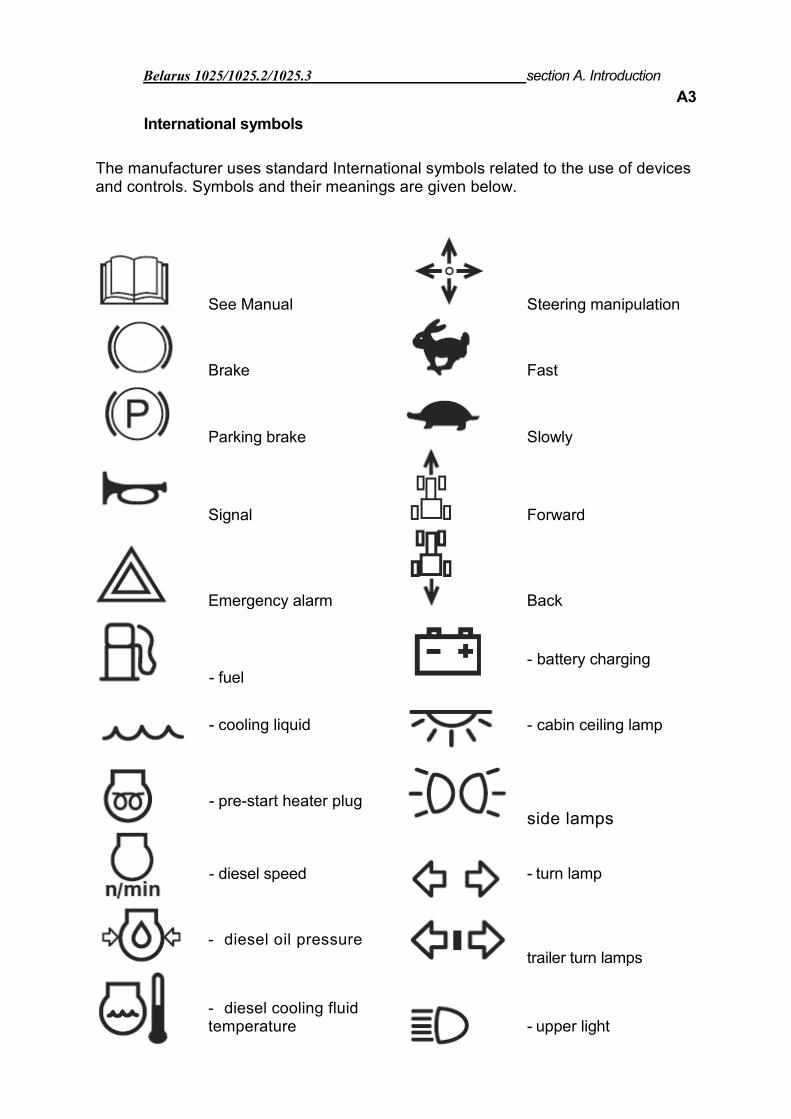
International symbols
The manufacturer uses standard International symbols related to the use of devices and controls. Symbols and their meanings are given below.
See Manual Steering manipulation
Brake Fast
Parking brake Slowly
Signal Forward
Emergency alarm Back
- fuel - battery charging
- cooling liquid
- cabin ceiling lamp
- pre-start heater plug side lamps
- diesel speed
- turn lamp
- diesel oil pressure trailer turn lamps
- diesel cooling fluid temperature
- upper light
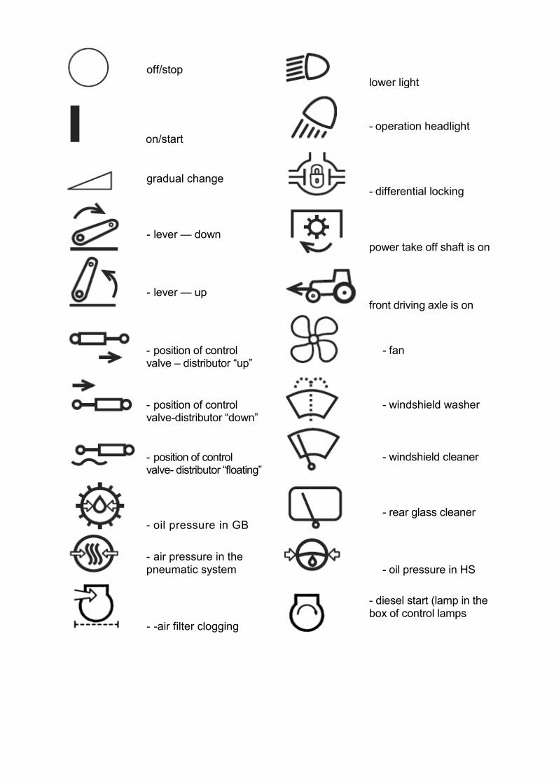
off/stop lower light
on/start - operation headlight
gradual change - differential locking
- lever — down power take off shaft is on
- lever — up front driving axle is on
- position of control valve – distributor “up”
- fan
- position of control valve-distributor “down”
- windshield washer
- position of control valve- distributor “floating”
- windshield cleaner
- oil pressure in GB - rear glass cleaner
- air pressure in the pneumatic system - oil pressure in HS
- -air filter clogging
- diesel start (lamp in the box of control lamps
Belarus Section B Safety requirements B1
Section B Safety requirements
Strict observance of precautionary measures and abidance by tractor control and maintenance directions guarantee complete safety of its operation. General directions Carefully study operator’s manual before using the tractor. Insufficient knowledge of tractor operation and maintenance may be the cause of accidents. 1. The tractor can be operated only
by trained and qualified specialists briefed on safety engineering and fire safety.
2. If tractor is provided with safety belt, use it during operation. If tractor is not equipped with safety belt, address your dealer.
3. Do not place a passenger in the cabin, unless additional seat and railing are provided. There is no other safe place for a passenger in the cabin!
4. Keep all warning plates tidy. 5. If plates are damaged or lost,
replace them with new ones. 6. Before starting work carefully
examine the tractor, trailing machine, mounted implement and hitch. Start the work only being sure they are fully operational. Trailing agricultural machinery and transport trailers must be provided with rigid hitches, excluding their sway and run-over during transportation.
Precautionary measures during tractor operation
Attention! Do not start the diesel being out of operator’s working seat. Stay always inside the cabin during diesel start up and controls manipulation.
7. Before starting the diesel, parking brake should be engaged, lever of power take-off shaft (PTO) in the position “off”, levers of range and GB gears shifting – in the position “neutral”. Switch of GB pump drive should be in position driven from “diesel”.
8. Do not start the diesel up and do not use control levers being out of operator’s working place.
9. Before starting movement warn people around and those working on trailing machines with a horn.
10. Do not leave the moving tractor. 11. Before leaving the cabin disengage
PTO, engage parking brake and pull out starter switching key.
12. Do not operate the tractor inside closed rooms not properly ventilated. Exhaust gases may be the cause of death!
13. When malfunction appears immediately stop the tractor and correct the trouble.
Belarus 1025/1025.2/1025.3 Section B. Safety requirementsB2
13.1. If diesel or steering wheel fail during operation, immediately stop the tractor. Remember that with diesel shut down much greater effort has to be applied to the steering wheel.
14. Do not work under lifted agricultural implements. During prolonged breaks do not leave mounted implement in lifted position.
15. If the front part of the tractor drives off the ground when mounting heavy machines and implements, put front load.
16. When operating with frontal loader fill rear tires with liquid ballast.
17. Before lifting or lowering a mounting agricultural implement, as well as when turning, make sure in advance that there is no danger of brushing against somebody, or hit against an obstacle.
18. During transport travel with mounted machines or implements always use mechanism for fixing the mounting in the lifted position (for HMS without hydraulic lift).
19. The gimbal gear for transferring rotation from tractor PTO to assembly tools should be protected.
20.Make sure any additional equipment or auxiliary devices are properly installed, and also that they are intended to be ganged up with your tractor. Remember, that if not properly operated, your tractor may be perilous both for you and other persons. Do not use equipment
not intended for use on yoyr tractor.
21. To avoid overturning take care when running the tractor. Choose safe speed in accordance with road conditions, in particular when travelling on cross-country terrain, across ditches, slopes and at sharp turns.
22. When operating on slopes expand tractor wheel span to maximum.
23. Do not turn sharp under full load and at high travelling speed.
24. When using tractor for transport purposes:
• Increase tractor wheel span up to 1600 mm (64’’);
• Interlock braking pedals, check and adjust brakes for synchronous action, if necessaryс;
• Check functioning of parking brake; • Check state of light and sound
alarms; • Transport trailers should be
provided with rigid hitch and additionally coupled by means safety chain or steel rope;
• Never move down the hill with gear disengaged (coasting). Move at one and the same gear both uphill and downhill;
• Do not operate the trailer without stand-alone brakes, if its mass exceeds by half total actual tractor mass. The faster you move and the larger the mass being towed, the larger safe distance should be;
• Disengage FDA to avoid excessive wear of driving parts and tires .
Belarus 1025/1025.2/1025.3 Section B. Safety requirements B3
• do not use rear axle differential interlock at speed over 10 km/h and when turning.
• Do not stop the tractor on slope. If the stop is necessary, put in the 1st gear and engage the parking brake.
25. When operating PTO driven equipment, before leaving the cabin to disconnect the equipment, shut down diesel and make sure PTO drive end fully stopped.
26. Do not put on loose clothes in the vicinity of PTO or rotating mechanisms.
27. When operating PTO driven stationary machines, always engage the parking brake and block rear wheels on both sides.. Make sure the machine is securely fixed.
28. Be sure to install fencing of PTO drive end, and if PTO is not used shift PTO range switch to middle position.
29. Do not make cleaning, adjustment or service of PTO driven equipment with running diesel.
Precautionary measures during maintenance
30. Never fill in the tractor with diesel running.
31. Do not smoke when filling tractor with fuel.
32. Do not fill in fuel tanks to the full. Have some space for fuel expansion.
33. Never add gasoline or other mixtures to diesel fuel. Such combinations may create
high danger of combustion or explosion. 34. Correctly use summer and winter
grades of fuel. Fill in the fuel tank at the end of each day to reduce night-time moisture condensation.
35. Perform all operations related to cleaning of diesel and tractor, preparation for work, maintenance and so on, with diesel shut down and tractor braked.
36. The cooling system is functioning under pressure, which is maintained by means of the valve installed in the filling neck cover. It is dangerous to remove cover on the hot diesel. To avoid burns of face and hands be careful to open the plug of radiator neck on the hot diesel. First, put tight cloth on the plug and put on a mitten.
37. To avoid burns take care when draining cooling fluid or water from the cooling system, hot oil from diesel, hydraulic system and transmission.
38. Take care when handling storage batteries, as electrolyte may cause burns when splashed on skin.
39. To avoid danger of explosion keep open flame sources away from diesel fuel system and storage batteries.
40. Keep tractor, brakes and steering in particular, operational for your own safety and those close by.
41. Do not make any alterations to the tractor or its individual components without approval of your dealer and manufacturer.
Belarus 1025/1025.2/1025.3 РSection B. Safety requirements
B 4
Otherwise tractor guarantee service is discontinued.
42. Fill the tractor only with oils and lubricants recommended by the manufacturer. The use of other lubricants strictly forbidden.!
Safety requirements in operating and maintaining electrical equipment
43. To avoid damage of semiconductor devices and resistors take the following precautions:
• do not disconnect storage batteries with running engine. This will result in peak voltage in the charge circuit and inevitable damage of diodes and transistors;
• do not disconnect electrical wiring before diesel is shut down and all electrical switches are off.;
• do not cause short-circuit due to wrong wiring connection. Short-circuiting or wrong polarity will cause damage of diodes and transistors;
• do not connect SB to the electrical equipment system until polarity of terminals and voltage are checked;
• do not check electric current ‘by spark”, as this will immediately lead to transistors’ break-down;
• do not switch of “ground” with diesel running;
• do not operate tractor without SB.
Hygiene requirements
• Daily fill thermal bottle with pure drinking water; • The first-aid kit must be staffed with bandages, iodine, salmiac, boric vaseline, soda, validole and analgine; • Depending on work conditions use natural cabin ventilation or air heating and cooling system. • During continuos work during the shift for over 2.5 hours, use individual noise protection means under GOST 12.4.051-87 (earphones).
Fire safety requirements.
1. Tractor has to be equipped with fire fighting means – a shovel and fire extinguisher. Do not operate the tractor without fire fighting tools. 2. Never fill in the tractor with running engine. 3. Do not smoke when filling the tractor with fuel. 4. Do not fill in fuel tanks to the full. Have some space for fuel expansion. 5. Never add gasoline or other mixtures to diesel fuel. Such combinations may create higher danger of inflammation or explosion. 6. Sites of tractors’ parking and storage of fuel and lubricants must be equipped with fire fighting means. 7. Fill tractors with fuel and lubricants mechanically with diesel shut down. Use illumination at night time.
Belarus 1025/1025.2/1025.3 section B. Safety requirements B5
Filling of fuel tanks using buckets is not recommended. 8. Clean parts and assembly units off vegetation remains when doing repairs in field conditions using electric-gas welding. 9. Do not allow staining of collector and muffler with dust, fuel, straw, etc.
10. Do not allow winding of straw on rotating parts of machines ganged up with tractor. 11. When rinsing parts and assembly units with kerosine and gasoline, take measures to prevent inflammation of rinsing fluid vapors. 12. Do not allow tractor operation in fire sensitive places with hood and other protective fixtures being taken off heated diesel parts.
13. Do not use open flame for heating oil in the diesel casing, when filling fuel tanks and burning stains in the radiator core. 14. When flame hotbed appears, cover it with sand, sacking or some other tight cloth. Use carbon-dioxide fire extinguisher. Do not pour water on burning fuel. 15. Avoid easily inflammable materials close by outlet manifold and muffler. 16. Switch off “ground” when tractor stops operation.
Belarus 1025/1025.2/1025.3 Section C. Technical data C1
Section C. TECHNICAL DATA
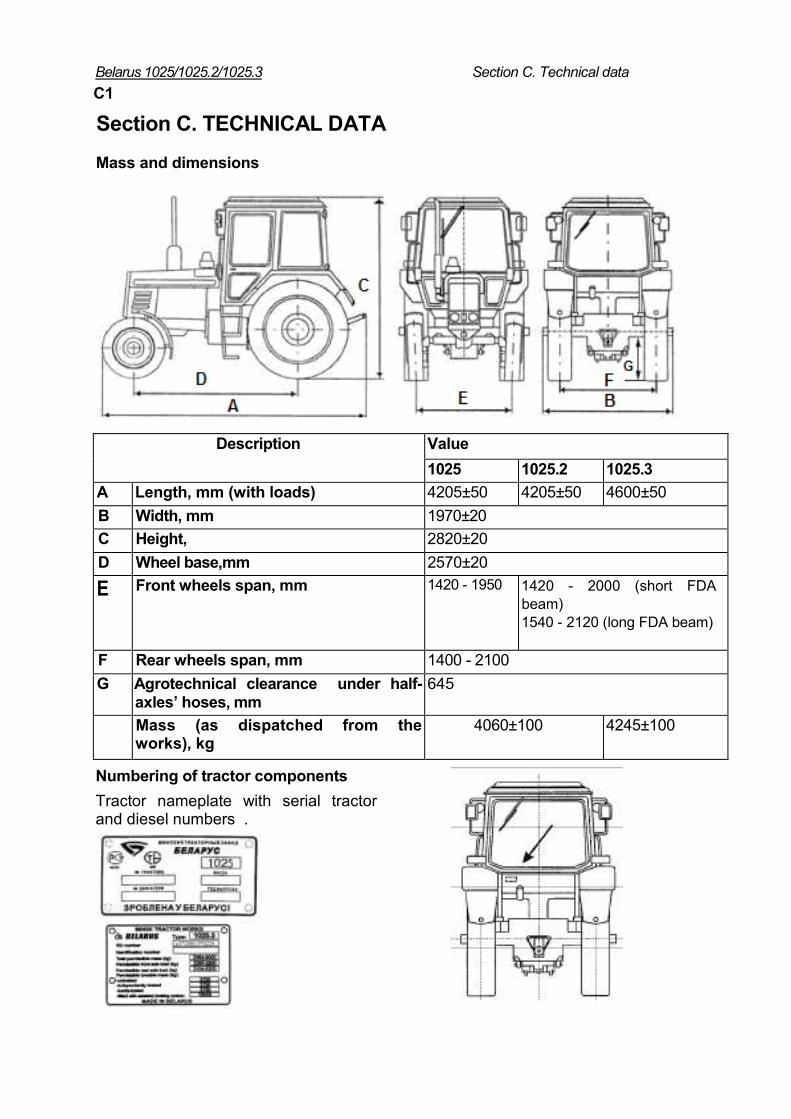
Mass and dimensions
Description Value
1025 1025.2 1025.3
А Length, mm (with loads) 4205±50 4205±50 4600±50
B Width, mm 1970±20
C Height, 2820±20
D Wheel base,mm 2570±20
E Front wheels span, mm 1420 - 1950 1420 - 2000 (short FDA beam) 1540 - 2120 (long FDA beam)
F Rear wheels span, mm 1400 - 2100
G Agrotechnical clearance under half-axles’ hoses, mm
645
Mass (as dispatched from the works), kg
4060±100 4245±100
Numbering of tractor components Tractor nameplate with serial tractor and diesel numbers .
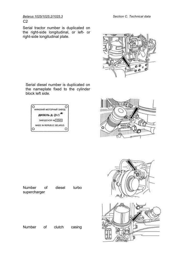
Belarus 1025/1025.2/1025.3 Section C. Technical data C2
Serial tractor number is duplicated on the right-side longitudinal, or left- or right-side longitudinal plate.
Serial diesel number is duplicated on the nameplate fixed to the cylinder block left side.
Number of diesel turbo supercharger Number of clutch casing
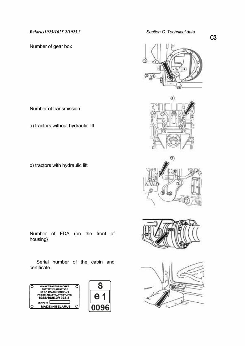
Belarus1025/1025.2/1025.3 Section C. Technical data C3
Number of gear box
Number of transmission
а) tractors without hydraulic lift
b) tractors with hydraulic lift
Number of FDA (on the front of housing}
Serial number of the cabin and certificate
Belarus 1025/1025.2/1025.3 Section C. Technical data C4
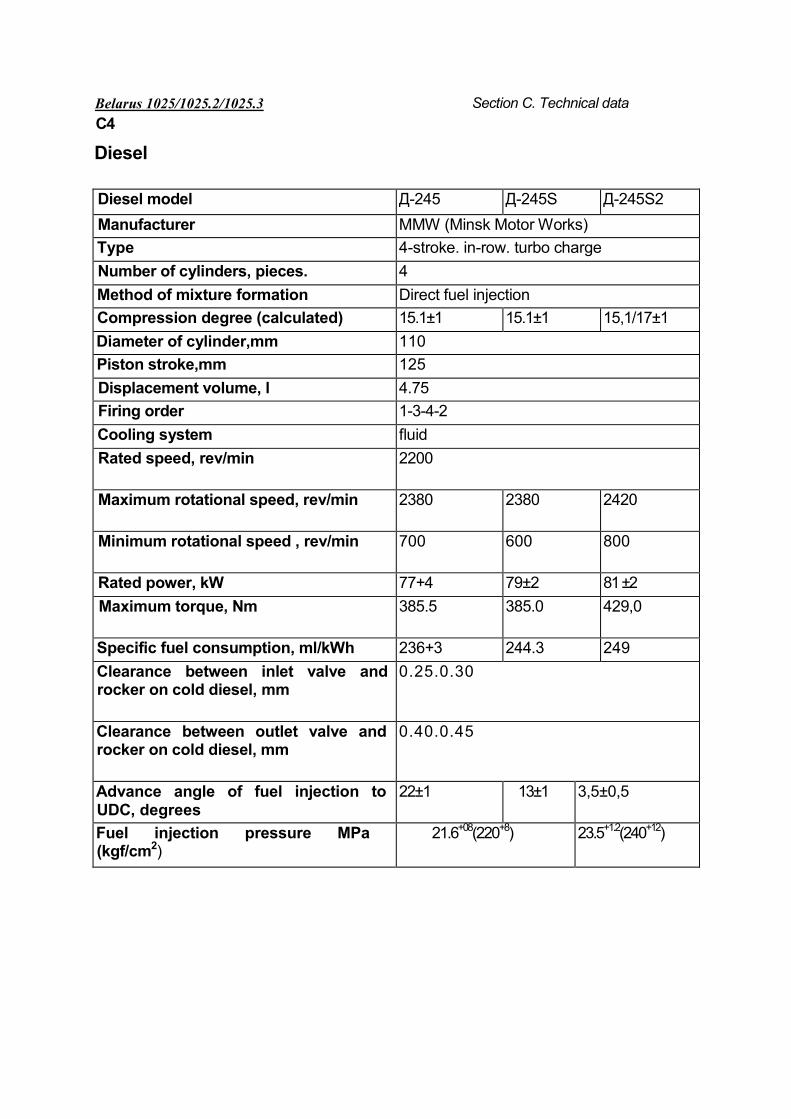
Diesel
Diesel model Д-245 Д-245S Д-245S2
Manufacturer MMW (Minsk Motor Works) Type 4-stroke. in-row. turbo charge
Number of cylinders, pieces. 4
Method of mixture formation Direct fuel injection
Compression degree (calculated) 15.1±1 15.1±1 15,1/17±1
Diameter of cylinder,mm 110
Piston stroke,mm 125
Displacement volume, l 4.75
Firing order 1-3-4-2
Cooling system fluid
Rated speed, rev/min 2200
Maximum rotational speed, rev/min 2380 2380 2420
Minimum rotational speed , rev/min 700 600 800
Rated power, kW 77+4 79±2 81 ±2
Maximum torque, Nm 385.5 385.0 429,0
Specific fuel consumption, ml/kWh 236+3 244.3 249
Clearance between inlet valve and rocker on cold diesel, mm
0.25.0.30
Clearance between outlet valve and rocker on cold diesel, mm
0.40.0.45
Advance angle of fuel injection to UDC, degrees
22±1 13±1 3,5±0,5
Fuel injection pressure MPa (kgf/cm2)
21.6+08(220+8) 23.5+1.2(240+12)
Belarus 1025/1025.2/1025.3 Section C. Technical data C5
Diesel fuel supply system
Fuel pump Type: four-plunger, in-row, with booster pump: Diesel D - 4 УТНИ-Т, НЗТА; Diesel Д-245S - РР4М10Р1f-3480 MOTORPAL or UTNI-Т or 773-01, YAZDA; D i e s e l Д - 2 4 5 S 2 - 7 7 3 - 0 1 Т , Y A Z D A ; Regulator: mechanical, centrifugal, all-mode, direct action, automatic increase of fuel supply during diesel start. Pressure of fuel injection start — 21.6+0,8МPa (220+8 kgf/cm2) for diesels Д-245, Д-245S; 23.5+1,2 MPa (240+12 кgf/cm2) for diesel Д-245S2. Nozzles: FDM-22 17.1112010-01 Diesel Д-245; 17.1112010-10 (MOTORPAL) or 171.1112010-01 diesel Д-245S ; 4 4 5 . 1 1 1 2 0 1 0 - 5 0 o r 172.1112010-11.01 diesel Д-245S2.
Air purifier
Combined: monocyclone (dry centrifugal purification) and air purifier with oil bath (for Д-245, Д-245S). With paper filtering element for Д-245S2. Turbo super charger: centripetal radial one-shaft turbine with centrifugal super charger can be used. Foreign-made turbo super chargers OHB (cooler of charged air for diesel Д-24582) installed in front of water radiator. It is intended for cooling air charged in the input diesel manifold.
Diesel cooling system Type: fluid, enclosed, with forced fluid circulation, temperature control using thermostat and radiator shutter, controlled from the operator’s seat (for Belarus 1025.3 – without the radiator shutter with expansion tank). Normal operation temperature from 80°С to 95°С. Cooling system capacity is 19 l. Cooling fluid OJ-40, OJ-65, Tosol A40M, Tosol A65M.
Diesel lubrication system
Type: combined with fluid-oil heat exchanger (FOE). Oil purification: centrifugal oil and meshed oil pre-filter. For diesel Д-245S2 filter with disposable paper filtering element is used. Minimum oil pressure is : 0.08 MPa (0.8 kgf/cm2) at 600 rev/min. Operation pressure is 0.2...0.3 MPa(2...3 kgf/cm2).Maximum pressure on the cold diesel is up to 0.6 MPa (6 kgf/cm2). Lubrication system capacity is 15 l.
Diesel starting system Electric starter of 24 V or (12 V optional), rated power 4.0 kW. Easy start device: - Д-245, Д-245S – electric torch heater; - Д-245S2 – spark plug . Generator Alternating current, rated voltage 14 v, power 1150 W.
Belarus 1025/1025.2/1025.3 Section C В. Technical data C6
Clutch Type: Dry, friction, two-disk. Mechanical drive. Disk diameter: 340 mm.
Gear box
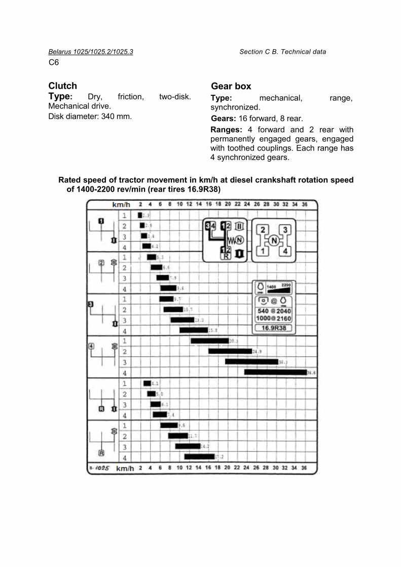
Type: mechanical, range, synchronized. Gears: 16 forward, 8 rear. Ranges: 4 forward and 2 rear with permanently engaged gears, engaged with toothed couplings. Each range has 4 synchronized gears.
Rated speed of tractor movement in km/h at diesel crankshaft rotation speed of 1400-2200 rev/min (rear tires 16.9R38)
Belarus 1025/1025.2/1025.3 Section C. Technical data
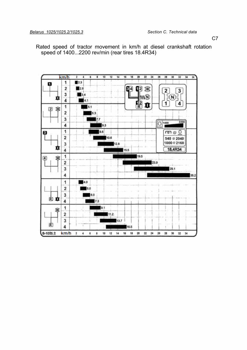
Rated speed of tractor movement in km/h at diesel crankshaft rotation speed of 1400...2200 rev/min (rear tires 18.4R34)
С7
Belarus 1025/1025.2/1025.3 Section C. Technical data C 8
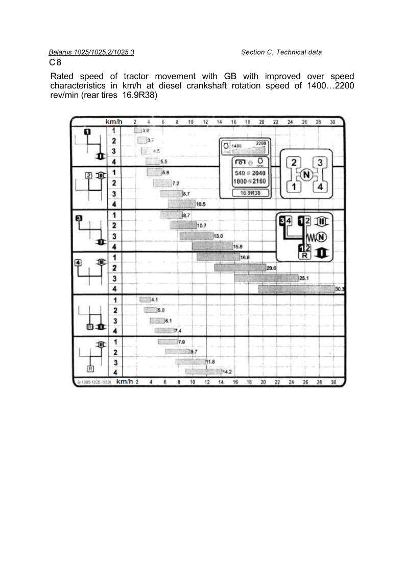
Rated speed of tractor movement with GB with improved over speed characteristics in km/h at diesel crankshaft rotation speed of 1400…2200 rev/min (rear tires 16.9R38)
Belarus 1025/1025.2/1025.3 Section C. Technical data C9
Rear axle Main gear: a pair of coned gears with circular tooth. Side gears: a pair of straight-toothed cylindrical gears for each side. Differential interlock mechanism: hydraulically driven friction clutch, dry or “wet”, (for tractors with “wet” brakes functioning in oil). Differential: coned with four satellites.
Brakes Wheel brakes: rear wheels; two- or three disk, dry or “wet” (optional), eight-disk with mechanical separate drive, pedals for each brake. Diameter of disks – 204 mm. Parking brake: rear wheels via differential to side gears. Disk-type, dry, with mechanical hand drive. Control lever is at the right hand of the operator. Diameter of disks is 180 mm.
Front driving axle (FDA)
Main gear: coned gears with circular tooth. Type of differential: self-locking with increased friction. End gears: coned (for 1025), or planetary-cylindrical wheel reduction gears (for 1025.2, 1025.3). Drive: built in GB cylindrical reduction gear and friction multi-disk “wet” clutch, propeller shaft.
FDA control: hydraulic with three operation modes: - FDA is switched off; - FDA switches on automatically (only with forward movement); - FDA is switched on by force.
Steering
Type: hydraulic, three dimensional (HS). Fuel pump: NSH14, gear-type, left-side rotation. Volumetric constant - 14 cm3/rev. Type of metering pump — gerotor. Volumetric constant 160 cm3/rev. Pressure of safety valve adjustment — 14 MPa (140 kgfс/cm2). Pressure of shock-proof valves adjustment — 20 MPa (200 kgf/cm2). Executive mechanism: two-way hydraulic cylinder. Diameter of cylinder — 63 mm, Cylinder stroke — 200 mm. Adjustment limits of steering wheel position: • tilt angle - from 25°to 40° with
fixation in 4 positions, • height in the range of 100 mm. Free steering wheel travel not more than 25°.
Belarus 1025/1025.2/1025.3 Section C. Technical data C 10
PTO drive Type: stand-alone, two-speed and synchronous
Switching clutch: planetary reduction gear with belt brakes. Drive: hydraulic-mechanical, lever at the right operator’ s hand. Revolutions of PTO drive end: Stand-alone drive
I — 540 rev/min at 2040 rev/min of diesel II — 1000 rev/min at 2160 rev/min of diesel. Synchronous drive 3.4 rev/m of travel on tires 16,9R38. 3.5 rev/m of travel on tires 18,4R38. PTO drive end: 8 splines (according to standard SAE with 6 splines) for 540 rev/min and 21 splines at 1000 rev/min. Rotation direction: clockwise, if looking at shaft end face. Hydraulic mounting system (HMS) Type: Belarus 1025 – remote-cyl inder system with power regulator; Belarus 1025.2/1025.3 – remote-cylinder with hydraulic lift, or (optional) with power regulator It provides control of agricultural implements position: • height control; • power control; • position control; • combined (mixed) control HMS with power regulator. Distributor: Р80-3/4-222-3Gg, of control valve type. It has the following positions: “lift”, “neutral”, “lowering” and “floating”. Position “lift” is fixed with automatic return to position “neutral” upon actuation of the safety valve
. Optionally, sectional distributor RS-213 Belarus, having improved leak tightness and reduced effort on control handles, can be installed. Positions “neutral” and “floating” are fixed. Power regulator — hydraulic control-valve distributor providing forced RMU lowering. Switch of control methods: mechanical, providing power, position and mixed methods of control. Power cylinder: Cylinder diameter — 125 mm, piston stroke — 200 mm. RMU RMU fixing mechanism
Type: Mechanical using gripper that locks rotation valve with tractor frame. Supply oil pump Type: gear. Pump capacity — at least 56 l/min at 2100 rev/min of diesel. Hydraulic system outlets: two side way, two rear way (one is back-up) and one drainage – for RS-213 Belarus; one side way, two rear way and one drainage for Р80-3/4-222-3Gg. Maximum hydraulic system pressure is 180... 200 kgf/cm2. HMU with hydraulic lift Regulator assembly is built in hydraulic lift housing. Forced RMU lowering is not available.
Belarus 1025/1025.2/1025.3 Section C. Technical data C11
Distributor: RP70 - 1221 or RS-213 Mita, of three sectional flow type. It has the following positions: “lift”, “neutral”, “lowering” and “floating”. Power cylinder: plunger cylinder (2 pieces) diameter — 80 mm, plunger stroke — 220 mm.
Rear mounting unit: Type: joint four-link. Load lifting capacity: at least 3.5 kN when braces are installed on additional points. Tractors equipped with power regulator have split lower tie-rods. Optionally, tie rods are one-piece (made of strip) or telescopic. Tractors with hydraulic lift are equipped with telescopic lower tie-rods, or as one-piece, optionally. *
Electrical equipment
Tractor-system voltage: 12 V. Power supply system: two storage batteries, 12 V each, capacity – 88 A/h. Alternating current generator with built-in rectifier and regulator, power 1150 W. Illumination and light alarm system: • front road headlights with lower and
higher light; • front and rear operation headlights; • front and rear lamps; • illumination of instruments panel and
license plate ;
• cabin illumination ceiling lamp; • emergency light alarm; • lamps of sign “long vehicle”. 0ther equipment: • sound alarm (buzzer).
It is switched on when diesel oil pressure drops to below rated value, or cooling fluid temperature exceeds the rated level;
• Front and rear glass wipers, windshield washer;
• Combination of devices, electrical tachometer-speedometer and boxes of control lamps.
Connecting electric power consumers: multi-terminal combined socket.
Pneumatic system Compressor Type: one-cylinder, air-cooled. Drive of trailer brake control Type0: pneumatic, one–wire, , interlocked with tractor brakes. Optionally, two-wired drive is provided.
Wheels Front: 13,6-20 (Belarus 1025) or 360/70R20; 360/70R24 (Belarus 1025.2/1025.3) Rear: 16,9R38 (Belarus 1025) или 18,4R34 (Belarus 1025.2/1025.3)
Belarus 1025/1025.2/1025.3 Section D.Controls and instruments
Section D. CONTROLS AND INSTRUMENTS
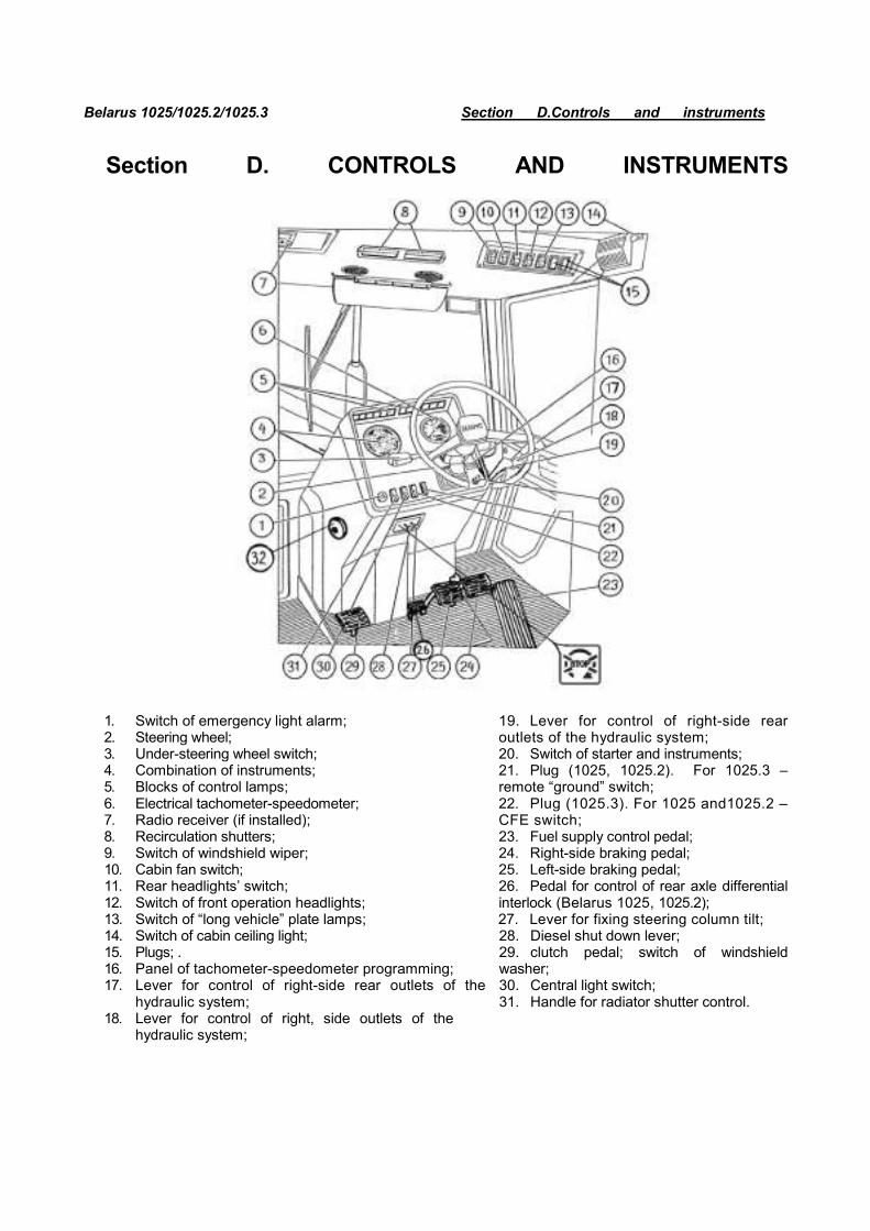
1. Switch of emergency light alarm; 2. Steering wheel; 3. Under-steering wheel switch; 4. Combination of instruments; 5. Blocks of control lamps; 6. Electrical tachometer-speedometer; 7. Radio receiver (if installed); 8. Recirculation shutters; 9. Switch of windshield wiper; 10. Cabin fan switch; 11. Rear headlights’ switch; 12. Switch of front operation headlights; 13. Switch of “long vehicle” plate lamps; 14. Switch of cabin ceiling light; 15. Plugs; . 16. Panel of tachometer-speedometer programming; 17. Lever for control of right-side rear outlets of the
hydraulic system; 18. Lever for control of right, side outlets of the
hydraulic system;
19. Lever for control of right-side rear outlets of the hydraulic system; 20. Switch of starter and instruments; 21. Plug (1025, 1025.2). For 1025.3 –remote “ground” switch; 22. Plug (1025.3). For 1025 and1025.2 –CFE switch; 23. Fuel supply control pedal; 24. Right-side braking pedal; 25. Left-side braking pedal; 26. Pedal for control of rear axle differential interlock (Belarus 1025, 1025.2); 27. Lever for fixing steering column tilt; 28. Diesel shut down lever; 29. clutch pedal; switch of windshield washer; 30. Central light switch; 31. Handle for radiator shutter control.
Belarus 1025/1025.2/1025.3 Section D.Controls and instruments D2
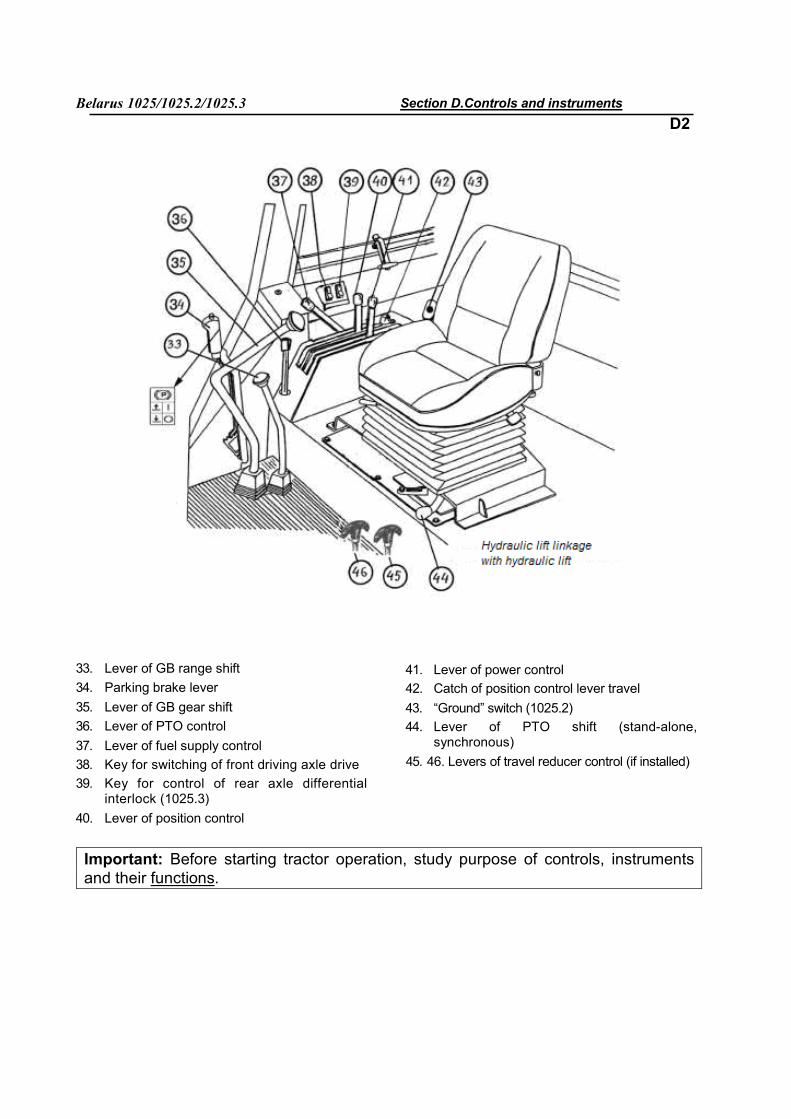
33. Lever of GB range shift 34. Parking brake lever 35. Lever of GB gear shift 36. Lever of PTO control 37. Lever of fuel supply control 38. Key for switching of front driving axle drive 39. Key for control of rear axle differential
interlock (1025.3) 40. Lever of position control
41. Lever of power control 42. Catch of position control lever travel 43. “Ground” switch (1025.2) 44. Lever of PTO shift (stand-alone,
synchronous) 45. 46. Levers of travel reducer control (if installed)
Important: Before starting tractor operation, study purpose of controls, instruments and their functions.
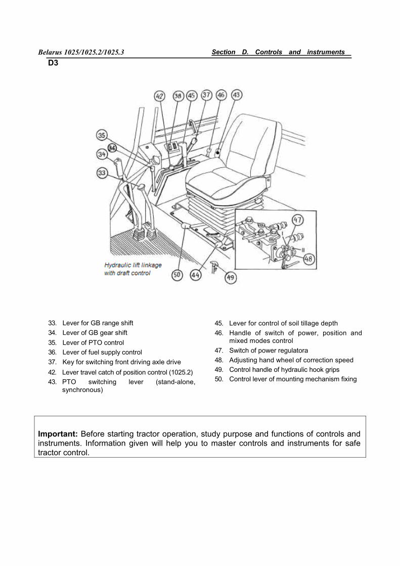
Belarus 1025/1025.2/1025.3 Section D. Controls and instruments D3
33. Lever for GB range shift 34. Lever of GB gear shift 35. Lever of PTO control 36. Lever of fuel supply control 37. Key for switching front driving axle drive
42. Lever travel catch of position control (1025.2) 43. PTO switching lever (stand-alone,
synchronous)
45. Lever for control of soil tillage depth 46. Handle of switch of power, position and
mixed modes control 47. Switch of power regulatorа 48. Adjusting hand wheel of correction speed 49. Control handle of hydraulic hook grips 50. Control lever of mounting mechanism fixing
Important: Before starting tractor operation, study purpose and functions of controls and instruments. Information given will help you to master controls and instruments for safe tractor control.
Belarus 1025/1025.2/1025.3 Section D. Controls and instruments D4
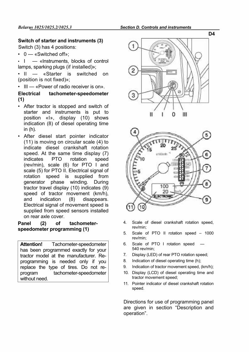
Switch of starter and instruments (3) Switch (3) has 4 positions: • 0 — «Switched off»; • I — «Instruments, blocks of control lamps, sparking plugs (if installed)»; • II — «Starter is switched on (position is not fixed)»; • III — «Power of radio receiver is on». Electrical tachometer-speedometer (1) • After tractor is stopped and switch of
starter and instruments is put to position «I», display (10) shows indication (8) of diesel operating time in (h).
• After diesel start pointer indicator (11) is moving on circular scale (4) to indicate diesel crankshaft rotation speed. At the same time display (7) indicates PTO rotation speed (rev/min), scale (6) for PTO I and scale (5) for PTO II. Electrical signal of rotation speed is supplied from generator phase winding. During tractor travel display (10) indicates (9) speed of tractor movement (km/h), and indication (8) disappears. Electrical signal of movement speed is supplied from speed sensors installed on rear axle cover.
Panel (2) of tachometer-speedometer programming (1)
Attention! Tachometer-speedometer has been programmed exactly for your tractor model at the manufacturer. Re-programming is needed only if you replace the type of tires. Do not re-program tachometer-speedometer without need.
4. Scale of diesel crankshaft rotation speed, rev/min;
5. Scale of PTO II rotation speed – 1000 rev/min;
6. Scale of PTO I rotation speed — 540 rev/min;
7. Display (LED) of rear PTO rotation speed; 8. Indication of diesel operating time (h); 9. Indication of tractor movement speed, (km/h); 10. Display (LCD) of diesel operating time and
tractor movement speed; 11. Pointer indicator of diesel crankshaft rotation
speed.
Directions for use of programming panel are given in section “Description and operation”.
Belarus 1025/1025.2/1025.3 Section D. Controls and instruments
D5
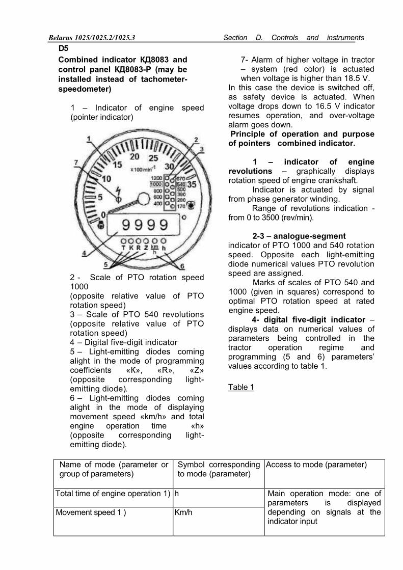
Combined indicator КД8083 and control panel КД8083-P (may be installed instead of tachometer-speedometer)
1 – Indicator of engine speed (pointer indicator)
2 - Scale of PTO rotation speed 1000 (opposite relative value of PTO rotation speed) 3 – Scale of PTO 540 revolutions (opposite relative value of PTO rotation speed) 4 – Digital five-digit indicator 5 – Light-emitting diodes coming alight in the mode of programming coefficients «К», «R», «Z» (opposite corresponding light-emitting diode). 6 – Light-emitting diodes coming alight in the mode of displaying movement speed «km/h» and total engine operation time «h» (opposite corresponding light-emitting diode).
7- Alarm of higher voltage in tractor – system (red color) is actuated when voltage is higher than 18.5 V.
In this case the device is switched off, as safety device is actuated. When voltage drops down to 16.5 V indicator resumes operation, and over-voltage alarm goes down. Principle of operation and purpose of pointers combined indicator.
1 – indicator of engine revolutions – graphically displays rotation speed of engine crankshaft.
Indicator is actuated by signal from phase generator winding.
Range of revolutions indication -from 0 to 3500 (rev/min).
2-3 – analogue-segment indicator of PTO 1000 and 540 rotation speed. Opposite each light-emitting diode numerical values PTO revolution speed are assigned.
Marks of scales of PTO 540 and 1000 (given in squares) correspond to optimal PTO rotation speed at rated engine speed.
4- digital five-digit indicator – displays data on numerical values of parameters being controlled in the tractor operation regime and programming (5 and 6) parameters’ values according to table 1.
Table 1
Name of mode (parameter or group of parameters)
Symbol corresponding to mode (parameter)
Access to mode (parameter)
Total time of engine operation 1) h Main operation mode: one of parameters is displayed depending on signals at the indicator input
Movement speed 1 ) Km/h
Belarus 1025/1025.2/1025.3 Section D. Controls and instruments D6
Precise total time of engine operation 1 )
Т Programming mode (access only from control panel)
Transfer coefficients 2) К
Radius of rear wheel rolling R
Number of gear teeth 3) Z
1 ) Access only for review. 2) Number of parameters in group – four: К1, К2, К3, К4 (see table 2). 3) Number of parameters in group - two: Z1, Z2 (see table 3)
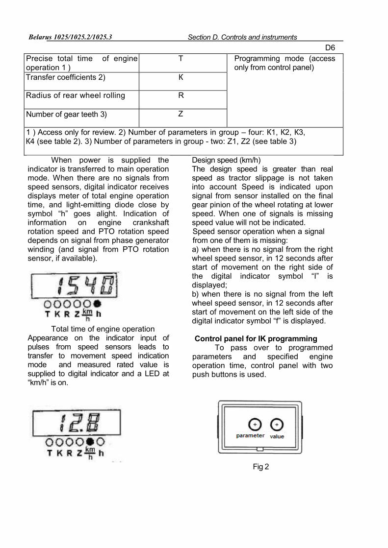
When power is supplied the indicator is transferred to main operation mode. When there are no signals from speed sensors, digital indicator receives displays meter of total engine operation time, and light-emitting diode close by symbol “h” goes alight. Indication of information on engine crankshaft rotation speed and PTO rotation speed depends on signal from phase generator winding (and signal from PTO rotation sensor, if available).
Total time of engine operation Appearance on the indicator input of pulses from speed sensors leads to transfer to movement speed indication mode and measured rated value is supplied to digital indicator and a LED at “km/h” is on.
Design speed (km/h) The design speed is greater than real speed as tractor slippage is not taken into account Speed is indicated upon signal from sensor installed on the final gear pinion of the wheel rotating at lower speed. When one of signals is missing speed value will not be indicated. Speed sensor operation when a signal from one of them is missing: а) when there is no signal from the right wheel speed sensor, in 12 seconds after start of movement on the right side of the digital indicator symbol “I” is displayed; b) when there is no signal from the left wheel speed sensor, in 12 seconds after start of movement on the left side of the digital indicator symbol “f” is displayed.
Control panel for IK programming To pass over to programmed
parameters and specified engine operation time, control panel with two push buttons is used.
Fig 2
Belarus 1025/1025.2/1025.3 Section D. Controls and instruments D7
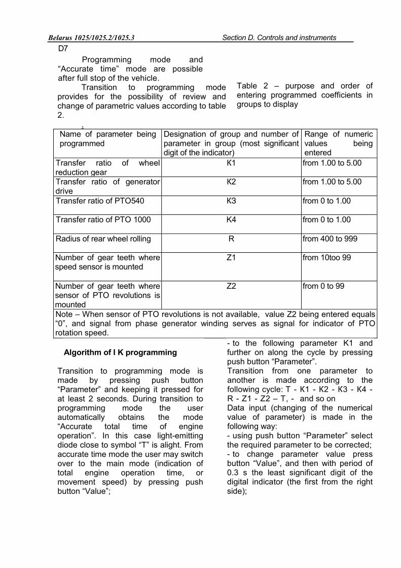
Programming mode and “Accurate time” mode are possible after full stop of the vehicle.
Transition to programming mode provides for the possibility of review and change of parametric values according to table 2.
. Name of parameter being programmed
Designation of group and number of parameter in group (most significant digit of the indicator)
Range of numeric values being entered
Transfer ratio of wheel reduction gear
К1 from 1.00 to 5.00
Transfer ratio of generator drive
К2 from 1.00 to 5.00
Transfer ratio of PTO540 КЗ from 0 to 1.00
Transfer ratio of PTO 1000 K4 from 0 to 1.00
Radius of rear wheel rolling R from 400 to 999
Number of gear teeth where speed sensor is mounted
Z1 from 10toо 99
Number of gear teeth where sensor of PTO revolutions is mounted
Z2 from 0 to 99
Note – When sensor of PTO revolutions is not available, value Z2 being entered equals “0”, and signal from phase generator winding serves as signal for indicator of PTO rotation speed.
Algorithm of I K programming
Transition to programming mode is made by pressing push button “Parameter” and keeping it pressed for at least 2 seconds. During transition to programming mode the user automatically obtains the mode “Accurate total time of engine operation”. In this case light-emitting diode close to symbol “T” is alight. From accurate time mode the user may switch over to the main mode (indication of total engine operation time, or movement speed) by pressing push button “Value”;
- to the following parameter K1 and further on along the cycle by pressing push button “Parameter”. Transition from one parameter to another is made according to the following cycle: Т - К1 - К2 - К3 - К4 - R - Z1 - Z2 – Т, - and so on Data input (changing of the numerical value of parameter) is made in the following way: - using push button “Parameter” select the required parameter to be corrected; - to change parameter value press button “Value”, and then with period of 0.3 s the least significant digit of the digital indicator (the first from the right side);
Table 2 – purpose and order of entering programmed coefficients in groups to display
Belarus 1025/1025.2/1025.3 Section D. Controls and instruments
- using push button “Value” set the required value of the least significant digit of the parameter selected; - press button “Parameter” for a short time, and the second to the right digit of the digital indicator should start flashing; - using button “Value” set the required value of the second to the right digit of the parameter being corrected; - press button “Parameter” for a short time, and the third to the right digit of the digital indicator should start flashing; - using button “value set the required value in the third to the right digit of the parameter being corrected; - fix the entered value by pressing button “Parameter”; - next pressing of button “Parameter” will result in transfer to the following parameter. Programming LED indicators’ operation of PTO rotation speed: - when sensor of PTO revolutions is not installed (signal from phase generator winding serves as signal for indication of PTO rotation speed), value of parameter Z2 being entered( number of pinion teeth where sensor of PTO revolutions is mounted) equals zero, and entered values of transfer ratios of PTO 540 (K3) and PTO 1000(K4) should correspond to a concrete tractor model and be in the range of 0.01…0.99), and value K3 being entered should be less then entered value K4.; - - when sensor of PTO revolutions is installed, value of parameter Z2 being entered should be in the range of 1…99, and o or 1 should be considered as values of coefficients K3 and K4 ( “1” if this PTO is used, and “0” – if this PTO is not used).
D8
Errors in indicator programming may occur if values of coefficients K3, K4, Z2 are entered in a wrong way: а) entered value КЗ>К4 (К3, К4 are not equal to «0» or «1»), and Z2=0 (i.e., signal from phase generator winding serves as signal for indication of PTO rotation speed); b) entered value К3<К4, but Z2^0, and К3, К4 are not equal to «0» or «1»; c) entered value К3=К4=0, (Z2 – any number other than «0»). If programming process has been interrupted due to supply voltage switch off, then upon switching it on the indicator will switch over to the mode of accurate time “T”, and flashing light-emitting diodes’ indicators «К», «R», and «Z» will be added, warning of the error made and programming process interruption. Programming mode is aborted: а) in 7-9 seconds (if errors were not made during data enter) after the last pressing of any button from any parameter being reviewed or programmed, except the mode of accurate time. In this case indicator goes over to the main operation mode (indication of total engine operation time or movement speed); b) from the mode “Accurate time” to the mode “Total time” when pressing button “Value”. If at the time of supply voltage switching off the indicator was in the mode of accurate time (and values of parameters accessible for programming didn’t change or were entered correctly), transition to main operation mode will be made without error indication.
Belarus 1025/1025.2/1025.3 Section D. Controls and instruments
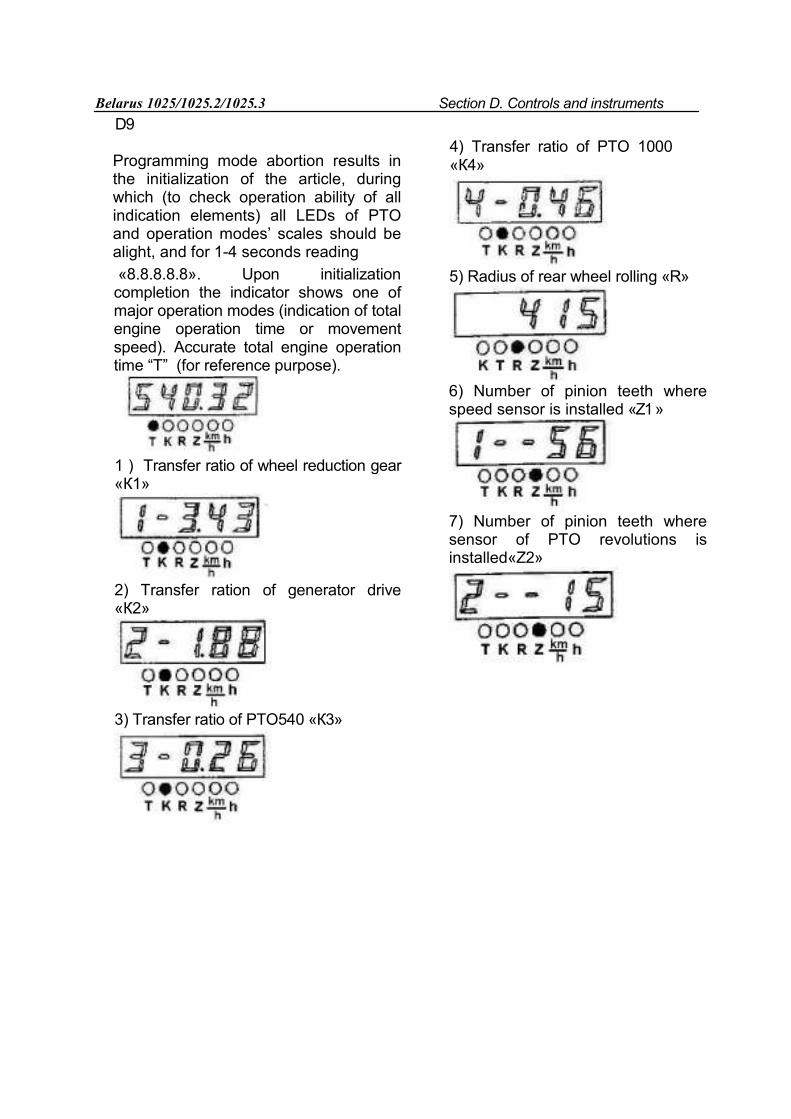
D9 Programming mode abortion results in the initialization of the article, during which (to check operation ability of all indication elements) all LEDs of PTO and operation modes’ scales should be alight, and for 1-4 seconds reading «8.8.8.8.8». Upon initialization completion the indicator shows one of major operation modes (indication of total engine operation time or movement speed). Accurate total engine operation time “T” (for reference purpose).
1 ) Transfer ratio of wheel reduction gear «К1»
2) Transfer ration of generator drive «К2»
3) Transfer ratio of PTO540 «К3»
4) Transfer ratio of PTO 1000 «К4»
5) Radius of rear wheel rolling «R»
6) Number of pinion teeth where speed sensor is installed «Z1 »
7) Number of pinion teeth where sensor of PTO revolutions is installed«Z2»
Belarus 1025/1025.2/1025.3 Section D. Controls and instruments
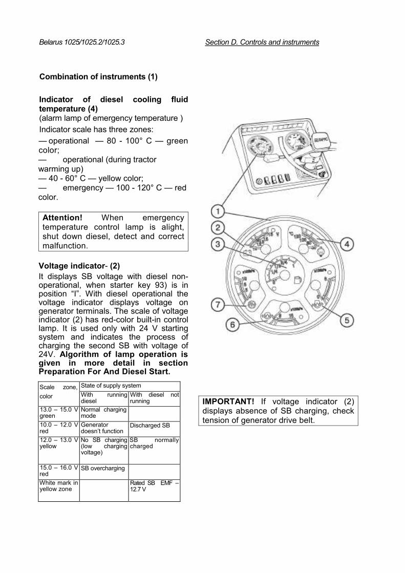
Combination of instruments (1)
Indicator of diesel cooling fluid temperature (4) (alarm lamp of emergency temperature ) Indicator scale has three zones: — operational — 80 - 100° С — green color; — operational (during tractor warming up) — 40 - 60° С — yellow color; — emergency — 100 - 120° С — red color.
Attention! When emergency temperature control lamp is alight, shut down diesel, detect and correct malfunction.
Voltage indicator- (2) It displays SB voltage with diesel non-operational, when starter key 93) is in position “I”. With diesel operational the voltage indicator displays voltage on generator terminals. The scale of voltage indicator (2) has red-color built-in control lamp. It is used only with 24 V starting system and indicates the process of charging the second SB with voltage of 24V. Algorithm of lamp operation is given in more detail in section Preparation For And Diesel Start.
Scale zone, color
State of supply system With running diesel
With diesel not running
13.0 – 15.0 V green
Normal charging mode
10.0 – 12.0 V red
Generator doesn’t function
Discharged SB
12.0 – 13.0 V yellow
No SB charging (low charging voltage)
SB normally charged
15.0 – 16.0 V red
SB overcharging
White mark in yellow zone
Rated SB EMF – 12.7 V
IMPORTANT! If voltage indicator (2) displays absence of SB charging, check tension of generator drive belt.
Belarus 1025/1025.2/1025.3 Section D. Controls and instruments D11
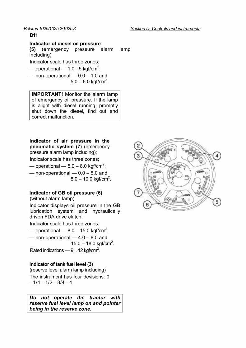
Indicator of diesel oil pressure (5) (emergency pressure alarm lamp including) Indicator scale has three zones: — operational — 1.0 - 5 kgf/cm2; — non-operational — 0.0 – 1.0 and
5.0 – 6.0 kgf/cm2.
IMPORTANT! Monitor the alarm lamp of emergency oil pressure. If the lamp is alight with diesel running, promptly shut down the diesel, find out and correct malfunction.
Indicator of air pressure in the pneumatic system (7) (emergency pressure alarm lamp including); Indicator scale has three zones; — operational — 5.0 – 8.0 kgf/cm2; — non-operational — 0.0 – 5.0 and
8.0 – 10.0 kgf/cm2.
Indicator of GB oil pressure (6) (without alarm lamp) Indicator displays oil pressure in the GB lubrication system and hydraulically driven FDA drive clutch. Indicator scale has three zones: — operational — 8.0 – 15.0 kgf/cm2; — non-operational — 4.0 – 8.0 and
15.0 – 18.0 kgf/cm2. Rated indications — 9... 12 kgf/cm2.
Indicator of tank fuel level (3) (reserve level alarm lamp including) The instrument has four devisions: 0 - 1/4 - 1/2 - 3/4 - 1.
Do not operate the tractor with reserve fuel level lamp on and pointer being in the reserve zone.
Belarus 1025/1025.2/1025.3 Section D. Controls and instruments
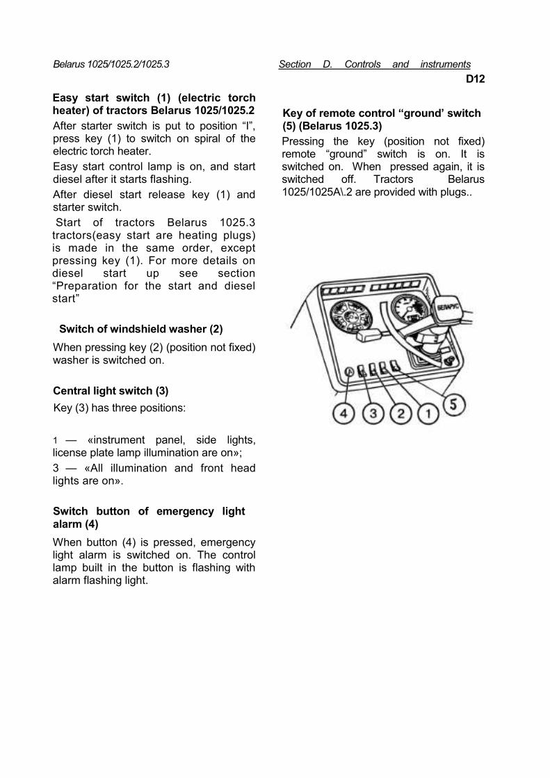
Easy start switch (1) (electric torch heater) of tractors Belarus 1025/1025.2
After starter switch is put to position “I”, press key (1) to switch on spiral of the electric torch heater. Easy start control lamp is on, and start diesel after it starts flashing. After diesel start release key (1) and starter switch. Start of tractors Belarus 1025.3 tractors(easy start are heating plugs) is made in the same order, except pressing key (1). For more details on diesel start up see section “Preparation for the start and diesel start”
Switch of windshield washer (2) When pressing key (2) (position not fixed) washer is switched on.
Central light switch (3) Key (3) has three positions: 1 — «instrument panel, side lights, license plate lamp illumination are on»; 3 — «All illumination and front head lights are on».
D12
Key of remote control “ground’ switch (5) (Belarus 1025.3) Pressing the key (position not fixed) remote “ground” switch is on. It is switched on. When pressed again, it is switched off. Tractors Belarus 1025/1025A\.2 are provided with plugs..
Switch button of emergency light alarm (4) When button (4) is pressed, emergency light alarm is switched on. The control lamp built in the button is flashing with alarm flashing light.
Belarus 1025/1025.2/1025.3 Section D. Controls and instruments
D13
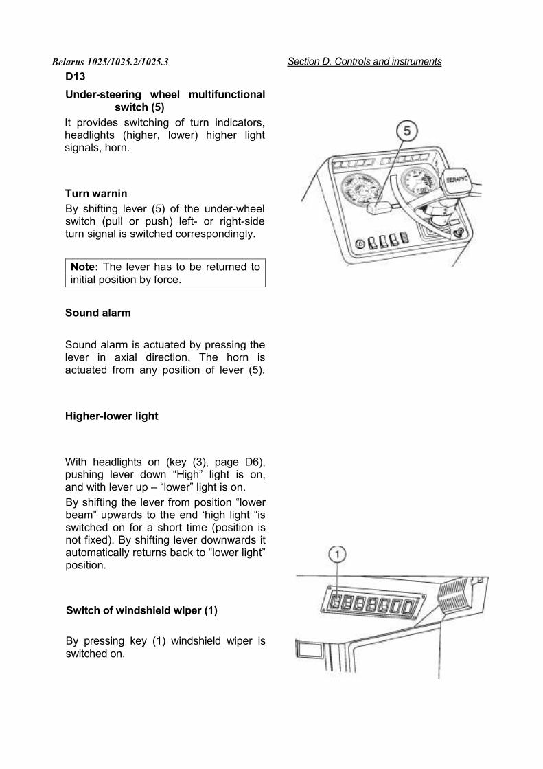
Under-steering wheel multifunctional switch (5)
It provides switching of turn indicators, headlights (higher, lower) higher light signals, horn.
Turn warnin By shifting lever (5) of the under-wheel switch (pull or push) left- or right-side turn signal is switched correspondingly.
Note: The lever has to be returned to initial position by force.
Sound alarm
Sound alarm is actuated by pressing the lever in axial direction. The horn is actuated from any position of lever (5).
Higher-lower light
With headlights on (key (3), page D6), pushing lever down “High” light is on, and with lever up – “lower” light is on. By shifting the lever from position “lower beam” upwards to the end ‘high light “is switched on for a short time (position is not fixed). By shifting lever downwards it automatically returns back to “lower light” position.
Switch of windshield wiper (1)
By pressing key (1) windshield wiper is switched on.
Belarus 1025/1025.2/1025.3 Section D. Controls and instruments D 14
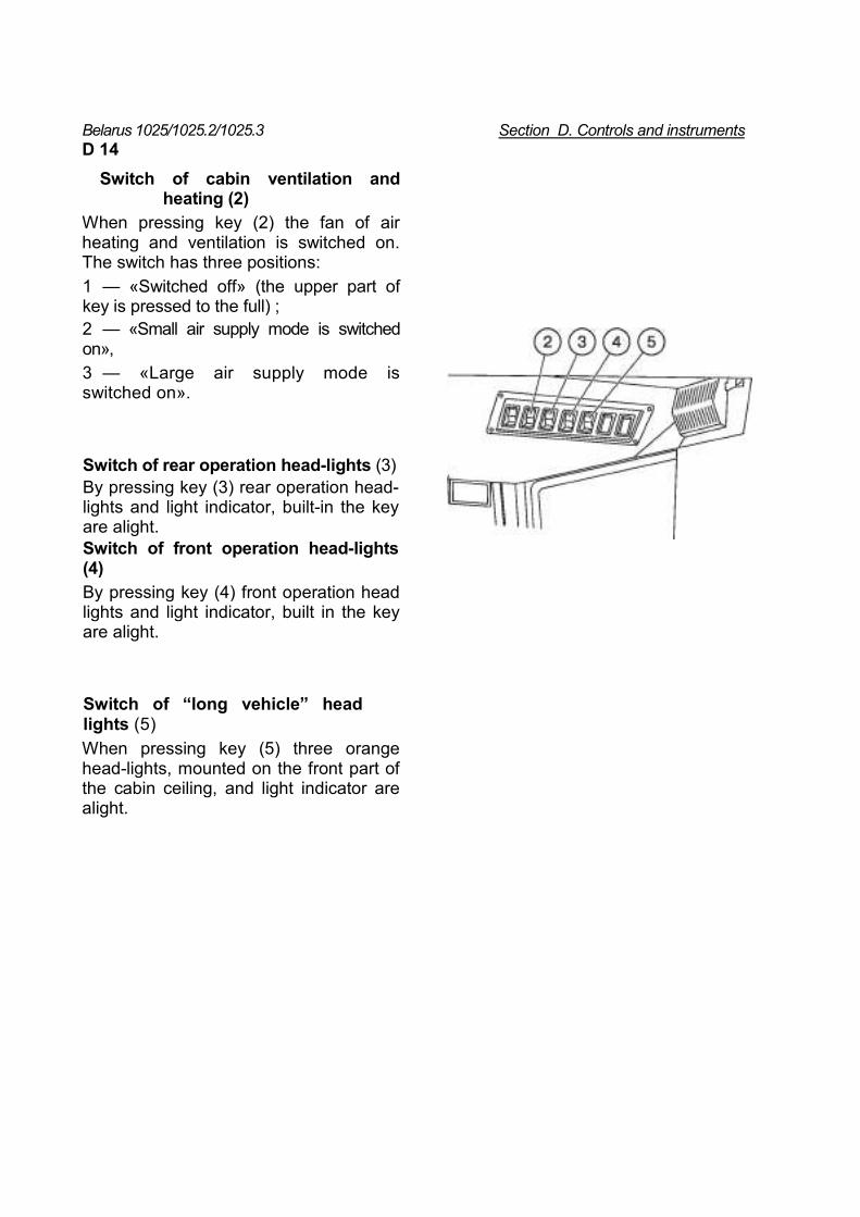
Switch of cabin ventilation and heating (2)
When pressing key (2) the fan of air heating and ventilation is switched on. The switch has three positions: 1 — «Switched off» (the upper part of key is pressed to the full) ; 2 — «Small air supply mode is switched on», 3 — «Large air supply mode is switched on».
Switch of rear operation head-lights (3) By pressing key (3) rear operation head-lights and light indicator, built-in the key are alight. Switch of front operation head-lights (4) By pressing key (4) front operation head lights and light indicator, built in the key are alight.
Switch of “long vehicle” head lights (5) When pressing key (5) three orange head-lights, mounted on the front part of the cabin ceiling, and light indicator are alight.
Belarus 1025/1025.2/1025.3 Section D .Controls and instruments D15
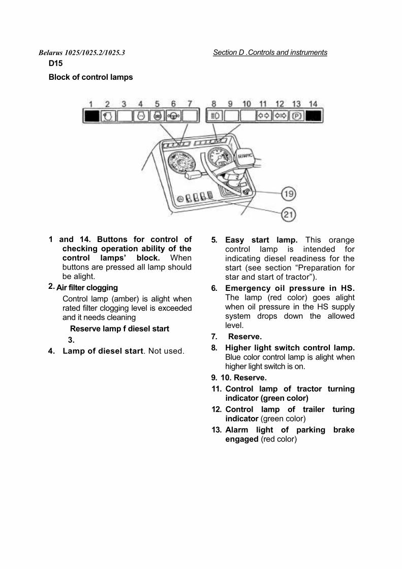
Block of control lamps
1 and 14. Buttons for control of checking operation ability of the control lamps’ block. When buttons are pressed all lamp should be alight.
Air filter clogging Control lamp (amber) is alight when rated filter clogging level is exceeded and it needs cleaning
Reserve lamp f diesel start 3.
4. Lamp of diesel start. Not used.
5. Easy start lamp. This orange control lamp is intended for indicating diesel readiness for the start (see section “Preparation for star and start of tractor”).
6. Emergency oil pressure in HS. The lamp (red color) goes alight when oil pressure in the HS supply system drops down the allowed level.
7. Reserve. 8. Higher light switch control lamp.
Blue color control lamp is alight when higher light switch is on.
9. 10. Reserve. 11. Control lamp of tractor turning
indicator (green color) 12. Control lamp of trailer turing
indicator (green color) 13. Alarm light of parking brake
engaged (red color)
2.
Belarus 1025/1025.2/1025.3 Section D. Controls and instruments D16
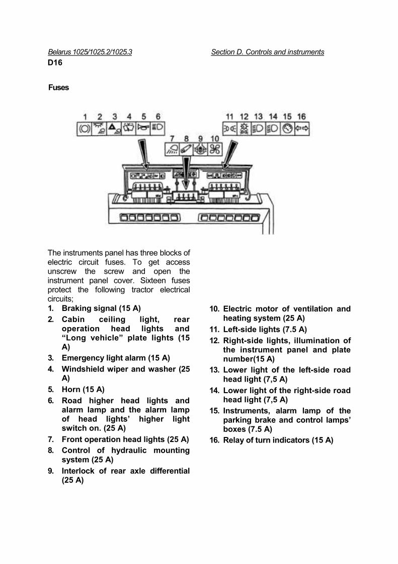
Fuses
The instruments panel has three blocks of electric circuit fuses. To get access unscrew the screw and open the instrument panel cover. Sixteen fuses protect the following tractor electrical circuits; 1. Braking signal (15 А) 2. Cabin ceiling light, rear
operation head lights and “Long vehicle” plate lights (15 А)
3. Emergency light alarm (15 А) 4. Windshield wiper and washer (25
А) 5. Horn (15 А) 6. Road higher head lights and
alarm lamp and the alarm lamp of head lights’ higher light switch on. (25 А)
7. Front operation head lights (25 А) 8. Control of hydraulic mounting
system (25 А) 9. Interlock of rear axle differential
(25 А)
10. Electric motor of ventilation and heating system (25 А)
11. Left-side lights (7.5 А) 12. Right-side lights, illumination of
the instrument panel and plate number(15 А)
13. Lower light of the left-side road head light (7,5 А)
14. Lower light of the right-side road head light (7,5 А)
15. Instruments, alarm lamp of the parking brake and control lamps’ boxes (7.5 А)
16. Relay of turn indicators (15 А)
Belarus 1025/1025.2/1025.3 Section D. Controls and instrumentsD17
Connecting elements of the electrical equipment
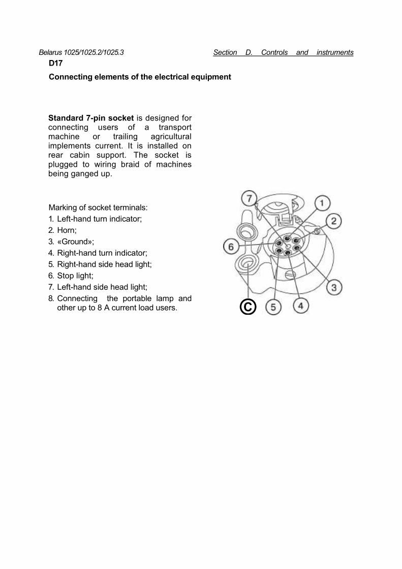
Standard 7-pin socket is designed for connecting users of a transport machine or trailing agricultural implements current. It is installed on rear cabin support. The socket is plugged to wiring braid of machines being ganged up.
Marking of socket terminals: 1. Left-hand turn indicator; 2. Horn; 3. «Ground»; 4. Right-hand turn indicator; 5. Right-hand side head light; 6. Stop light; 7. Left-hand side head light; 8. Connecting the portable lamp and
other up to 8 A current load users. ©
Belarus 1025/1025.2/1025.3 Section D. Controls and instruments D18
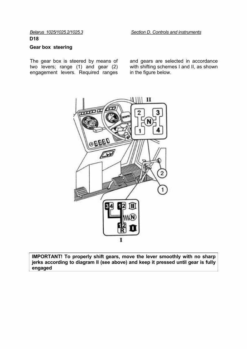
Gear box steering
The gear box is steered by means of two levers; range (1) and gear (2) engagement levers. Required ranges
and gears are selected in accordance with shifting schemes I and II, as shown in the figure below.
IMPORTANT! To properly shift gears, move the lever smoothly with no sharp jerks according to diagram II (see above) and keep it pressed until gear is fully engaged
Belarus 1025/1025.2/1025.3 Section D. Controls and instrumenmts
D19
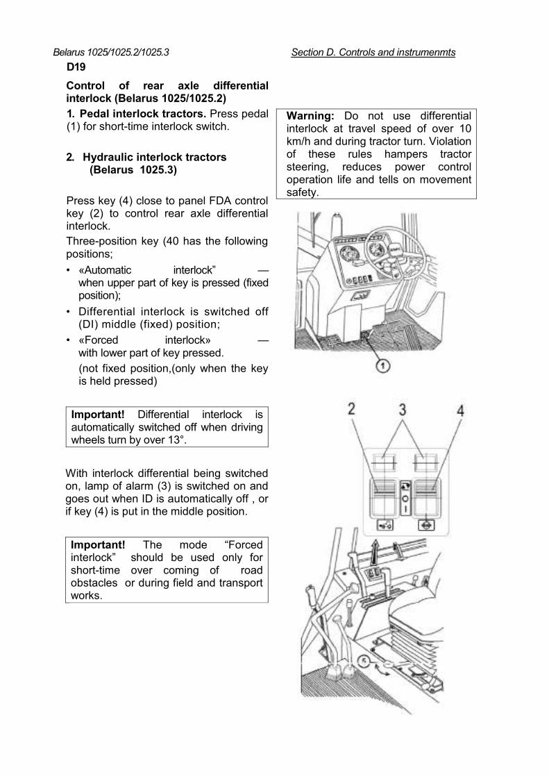
Control of rear axle differential interlock (Belarus 1025/1025.2) 1. Pedal interlock tractors. Press pedal (1) for short-time interlock switch.
2. Hydraulic interlock tractors (Belarus 1025.3)
Press key (4) close to panel FDA control key (2) to control rear axle differential interlock. Three-position key (40 has the following positions; • «Automatic interlock” —
when upper part of key is pressed (fixed position);
• Differential interlock is switched off (DI) middle (fixed) position;
• «Forced interlock» — with lower part of key pressed. (not fixed position,(only when the key is held pressed)
Important! Differential interlock is automatically switched off when driving wheels turn by over 13°.
With interlock differential being switched on, lamp of alarm (3) is switched on and goes out when ID is automatically off , or if key (4) is put in the middle position.
Important! The mode “Forced interlock” should be used only for short-time over coming of road obstacles or during field and transport works.
Warning: Do not use differential interlock at travel speed of over 10 km/h and during tractor turn. Violation of these rules hampers tractor steering, reduces power control operation life and tells on movement safety.
Belarus 1025/1025.2/1025.3 Section S. Controls and instruments
Control of RMU fixing mechanism (HMU without hydraulic lift) Lever (5) (see figure on page D 14): • «RMU is interlocked» — the end left-
hand position (as tractor moves)-
D20 To interlock the implement lift it to the top utmost position by having moved power mode control lever to the utmost rear position and then turning it to the left-hand end position. To unlock RMU lift the implement and shift the lever to the end right-hand position.
• «RMU is unlocked » — the end right-hand position.
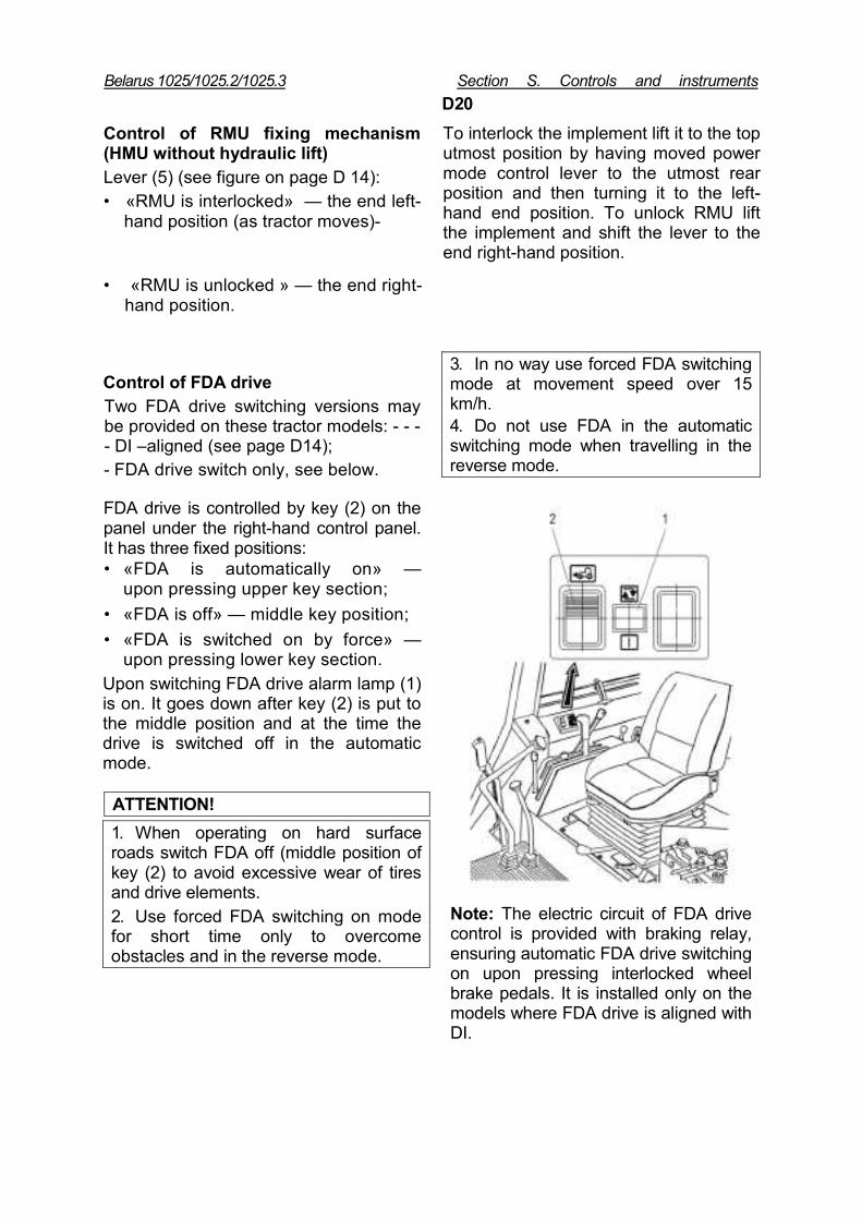
Control of FDA drive Two FDA drive switching versions may be provided on these tractor models: - - - - DI –aligned (see page D14); - FDA drive switch only, see below.
FDA drive is controlled by key (2) on the panel under the right-hand control panel. It has three fixed positions: • «FDA is automatically on» —
upon pressing upper key section; • «FDA is off» — middle key position; • «FDA is switched on by force» —
upon pressing lower key section. Upon switching FDA drive alarm lamp (1) is on. It goes down after key (2) is put to the middle position and at the time the drive is switched off in the automatic mode.
ATTENTION! 1. When operating on hard surface roads switch FDA off (middle position of key (2) to avoid excessive wear of tires and drive elements. 2. Use forced FDA switching on mode for short time only to overcome obstacles and in the reverse mode.
3. In no way use forced FDA switching mode at movement speed over 15 km/h. 4. Do not use FDA in the automatic switching mode when travelling in the reverse mode.
Note: The electric circuit of FDA drive control is provided with braking relay, ensuring automatic FDA drive switching on upon pressing interlocked wheel brake pedals. It is installed only on the models where FDA drive is aligned with DI.
Belarus 1025/1025.2/1025.3 Section D. Controls and instruments
D21
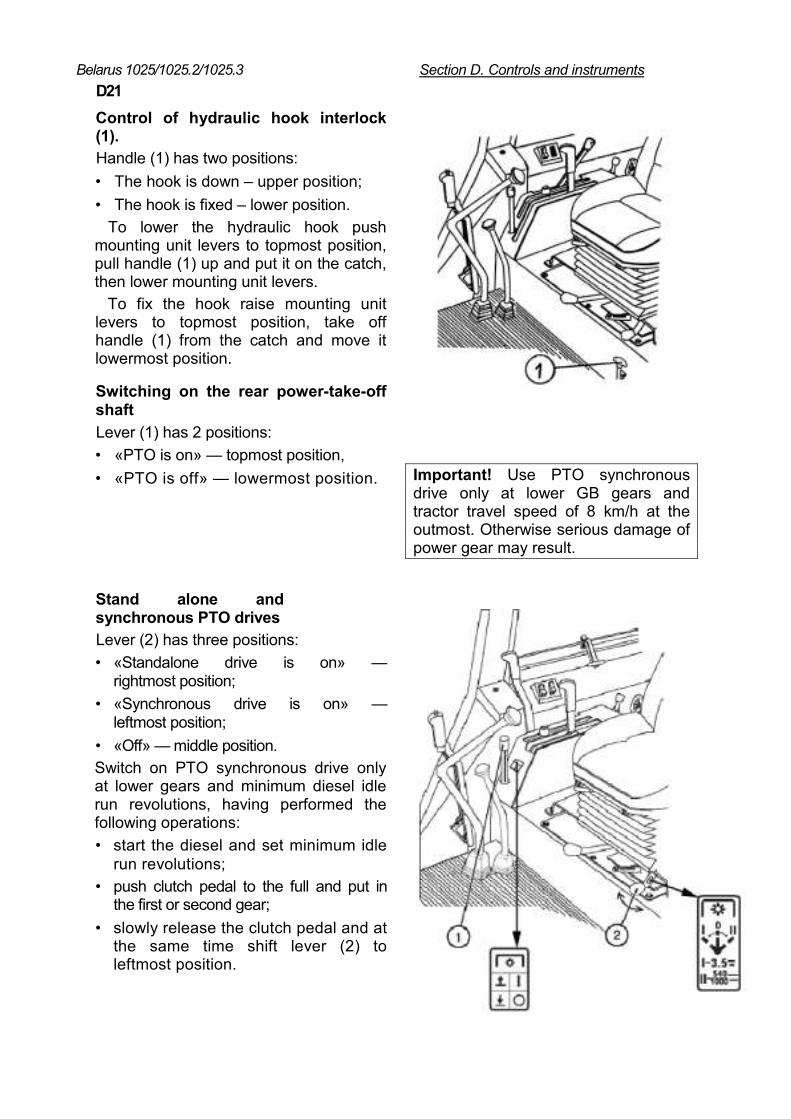
Control of hydraulic hook interlock (1). Handle (1) has two positions: • The hook is down – upper position; • The hook is fixed – lower position.
To lower the hydraulic hook push mounting unit levers to topmost position, pull handle (1) up and put it on the catch, then lower mounting unit levers.
To fix the hook raise mounting unit levers to topmost position, take off handle (1) from the catch and move it lowermost position.
Switching on the rear power-take-off shaft Lever (1) has 2 positions: • «PTO is on» — topmost position, • «PTO is off» — lowermost position.
Important! Use PTO synchronous drive only at lower GB gears and tractor travel speed of 8 km/h at the outmost. Otherwise serious damage of power gear may result.
Stand alone and synchronous PTO drives
Lever (2) has three positions: • «Standalone drive is on» —
rightmost position; • «Synchronous drive is on» —
leftmost position; • «Off» — middle position. Switch on PTO synchronous drive only at lower gears and minimum diesel idle run revolutions, having performed the following operations: • start the diesel and set minimum idle
run revolutions; • push clutch pedal to the full and put in
the first or second gear; • slowly release the clutch pedal and at
the same time shift lever (2) to leftmost position.
Belarus /1025.3 Section D. Controls and instruments D22
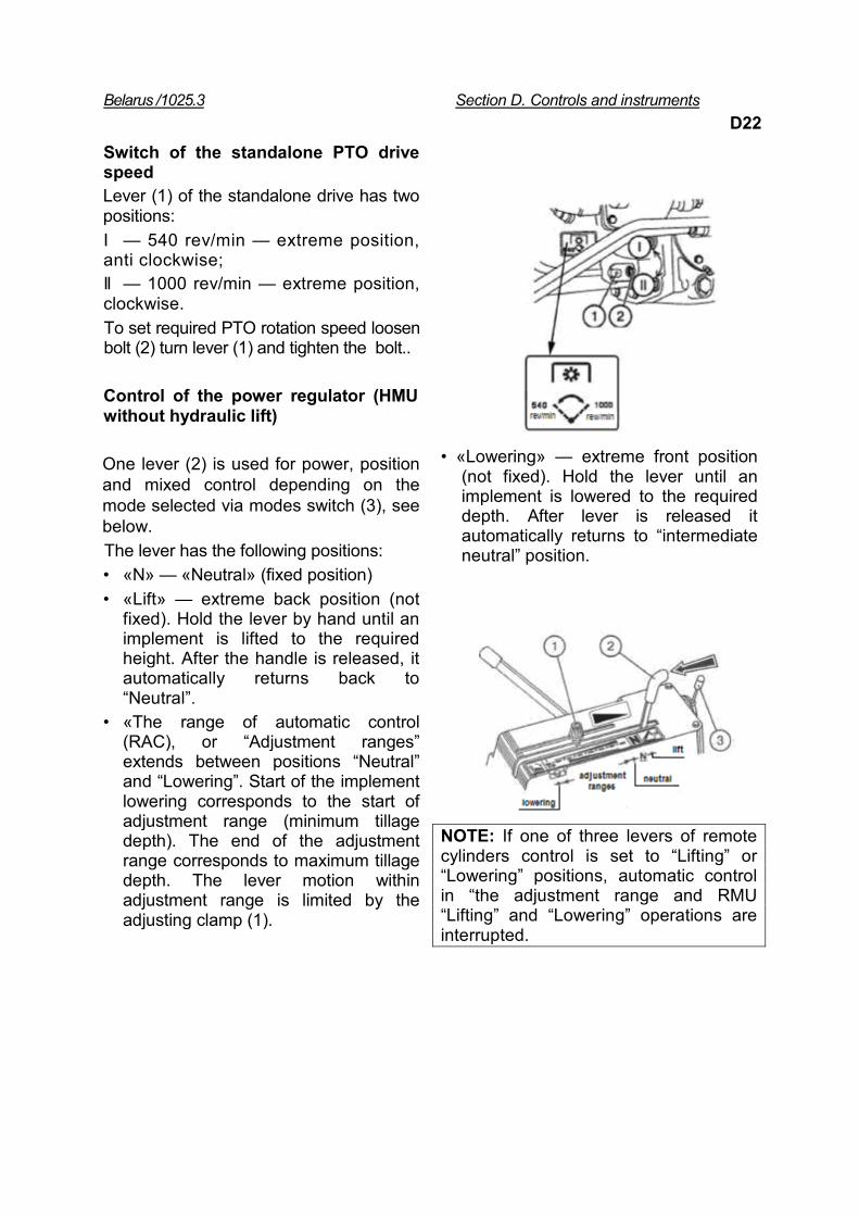
Switch of the standalone PTO drive speed Lever (1) of the standalone drive has two positions: I — 540 rev/min — extreme position, anti clockwise; II — 1000 rev/min — extreme position, clockwise. To set required PTO rotation speed loosen bolt (2) turn lever (1) and tighten the bolt..
Control of the power regulator (HMU without hydraulic lift)
One lever (2) is used for power, position and mixed control depending on the mode selected via modes switch (3), see below. The lever has the following positions: • «N» — «Neutral» (fixed position) • «Lift» — extreme back position (not
fixed). Hold the lever by hand until an implement is lifted to the required height. After the handle is released, it automatically returns back to “Neutral”.
• «The range of automatic control (RAC), or “Adjustment ranges” extends between positions “Neutral” and “Lowering”. Start of the implement lowering corresponds to the start of adjustment range (minimum tillage depth). The end of the adjustment range corresponds to maximum tillage depth. The lever motion within adjustment range is limited by the adjusting clamp (1).
• «Lowering» — extreme front position
(not fixed). Hold the lever until an implement is lowered to the required depth. After lever is released it automatically returns to “intermediate neutral” position.
NOTE: If one of three levers of remote cylinders control is set to “Lifting” or “Lowering” positions, automatic control in “the adjustment range and RMU “Lifting” and “Lowering” operations are interrupted.
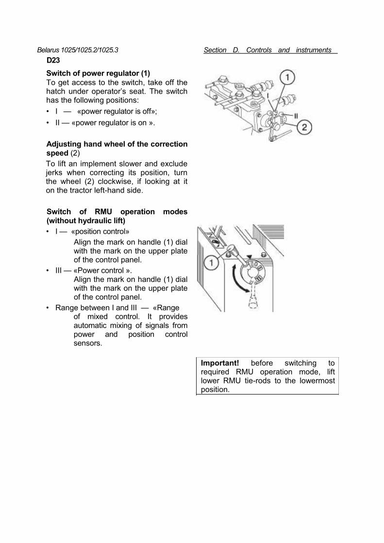
Belarus 1025/1025.2/1025.3 Section D. Controls and instruments D23
Switch of power regulator (1) To get access to the switch, take off the hatch under operator’s seat. The switch has the following positions: • I — «power regulator is off»; • II — «power regulator is on ».
Adjusting hand wheel of the correction speed (2) To lift an implement slower and exclude jerks when correcting its position, turn the wheel (2) clockwise, if looking at it on the tractor left-hand side.
Switch of RMU operation modes (without hydraulic lift) • I — «position control»
Align the mark on handle (1) dial with the mark on the upper plate of the control panel.
• III — «Power control ». Align the mark on handle (1) dial with the mark on the upper plate of the control panel.
• Range between I and III — «Range of mixed control. It provides automatic mixing of signals from power and position control sensors.
Important! before switching to required RMU operation mode, lift lower RMU tie-rods to the lowermost position.
Belarus 1025/1025.2/1025.3 Section D. Controls and instruments D24
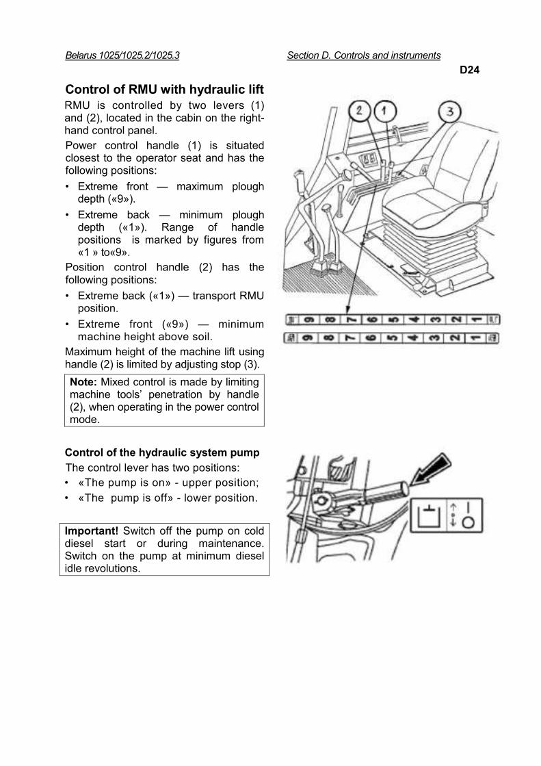
Control of RMU with hydraulic lift
RMU is controlled by two levers (1) and (2), located in the cabin on the right-hand control panel. Power control handle (1) is situated closest to the operator seat and has the following positions: • Extreme front — maximum plough
depth («9»). • Extreme back — minimum plough
depth («1»). Range of handle positions is marked by figures from «1 » to«9».
Position control handle (2) has the following positions: • Extreme back («1») — transport RMU
position. • Extreme front («9») — minimum
machine height above soil. Maximum height of the machine lift using handle (2) is limited by adjusting stop (3). Note: Mixed control is made by limiting machine tools’ penetration by handle (2), when operating in the power control mode.
Control of the hydraulic system pump
The control lever has two positions: • «The pump is on» - upper position; • «The pump is off» - lower position.
Important! Switch off the pump on cold diesel start or during maintenance. Switch on the pump at minimum diesel idle revolutions.
Belarus 1025/1025.2/1025.3 Section D Controls and instruments D25
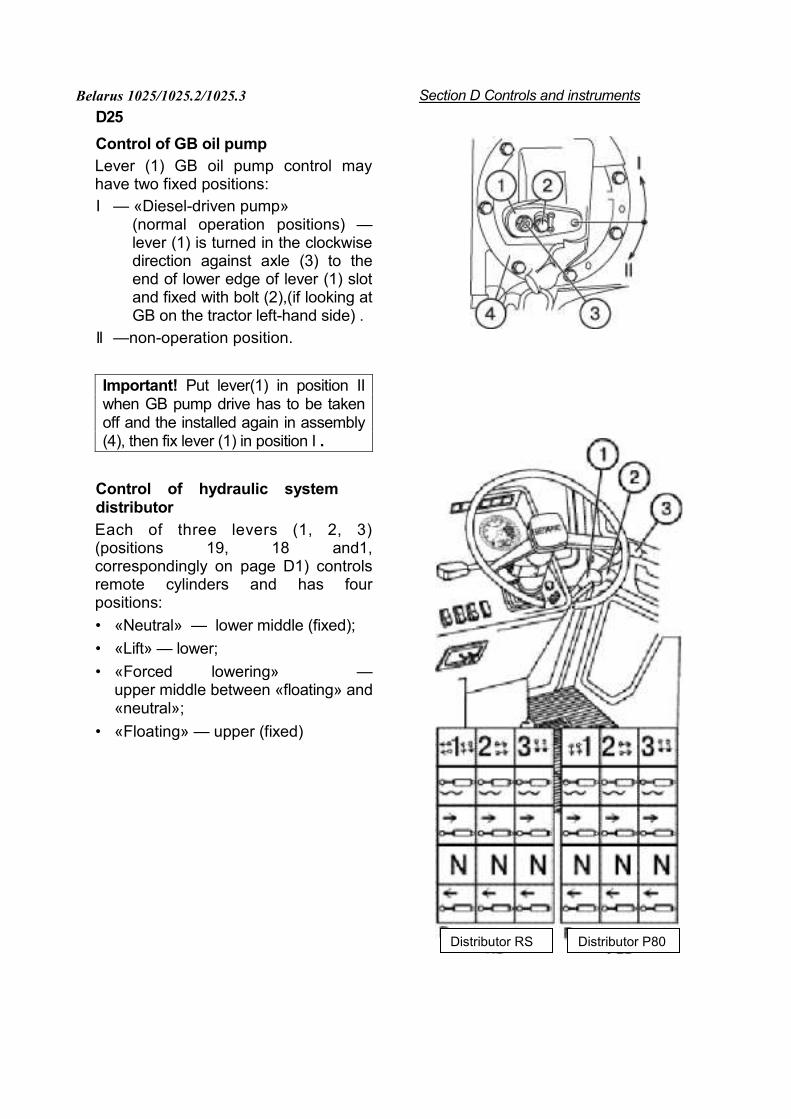
Control of GB oil pump Lever (1) GB oil pump control may have two fixed positions: I — «Diesel-driven pump»
(normal operation positions) — lever (1) is turned in the clockwise direction against axle (3) to the end of lower edge of lever (1) slot and fixed with bolt (2),(if looking at GB on the tractor left-hand side) .
II —non-operation position.
Important! Put lever(1) in position II when GB pump drive has to be taken off and the installed again in assembly (4), then fix lever (1) in position I .
Control of hydraulic system distributor
Each of three levers (1, 2, 3) (positions 19, 18 and1, correspondingly on page D1) controls remote cylinders and has four positions: • «Neutral» — lower middle (fixed); • «Lift» — lower; • «Forced lowering» —
upper middle between «floating» and «neutral»;
• «Floating» — upper (fixed)
Distributor RS Distributor P80
Belarus 1025/1025.2/1025.3 Section D. Controls and instruments D26
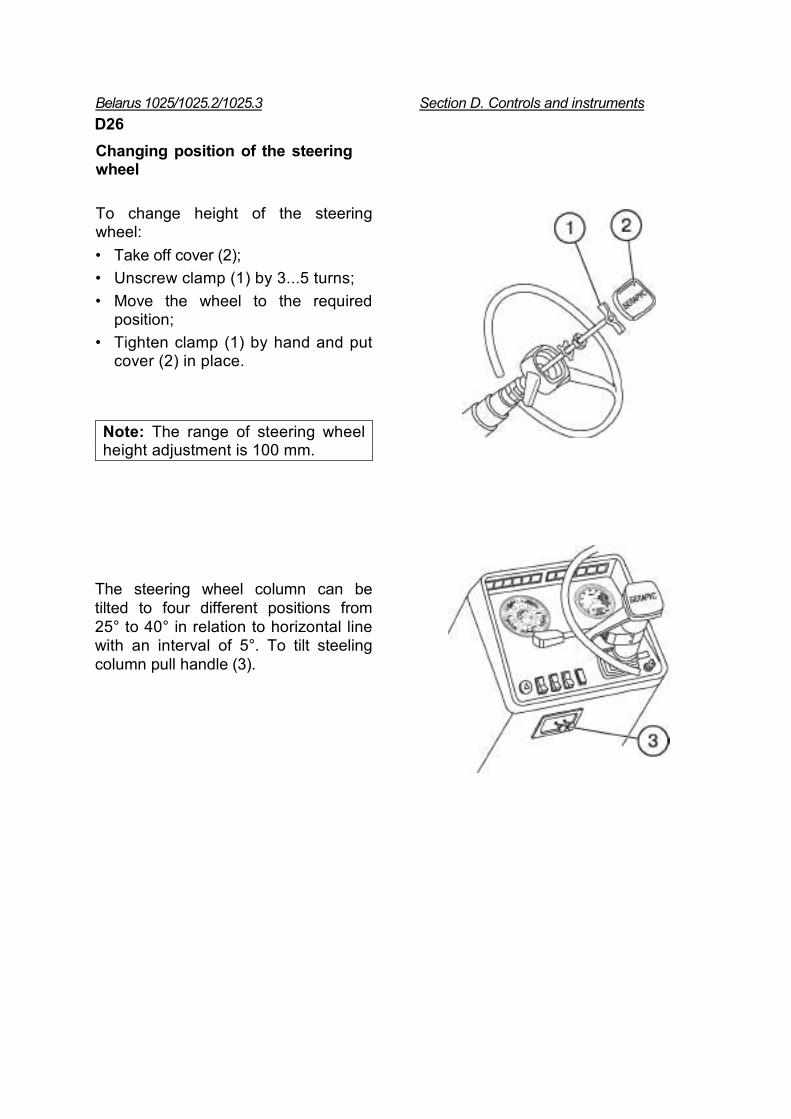
Changing position of the steering wheel
To change height of the steering wheel: • Take off cover (2); • Unscrew clamp (1) by 3...5 turns; • Move the wheel to the required
position; • Tighten clamp (1) by hand and put
cover (2) in place.
Note: The range of steering wheel height adjustment is 100 mm.
The steering wheel column can be tilted to four different positions from 25° to 40° in relation to horizontal line with an interval of 5°. To tilt steeling column pull handle (3).
Belarus 1025/1025.2/1025.3 Section D. Controls and instruments D27
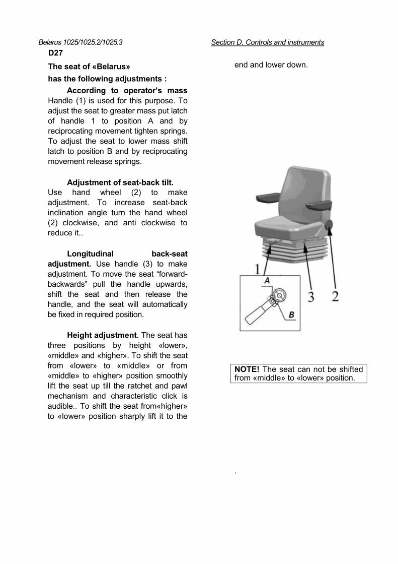
The seat of «Belarus» has the following adjustments :
According to operator’s mass Handle (1) is used for this purpose. To adjust the seat to greater mass put latch of handle 1 to position A and by reciprocating movement tighten springs. To adjust the seat to lower mass shift latch to position B and by reciprocating movement release springs.
Adjustment of seat-back tilt. Use hand wheel (2) to make adjustment. To increase seat-back inclination angle turn the hand wheel (2) clockwise, and anti clockwise to reduce it..
Longitudinal back-seat adjustment. Use handle (3) to make adjustment. To move the seat “forward-backwards” pull the handle upwards, shift the seat and then release the handle, and the seat will automatically be fixed in required position.
Height adjustment. The seat has three positions by height «lower», «middle» and «higher». To shift the seat from «lower» to «middle» or from «middle» to «higher» position smoothly lift the seat up till the ratchet and pawl mechanism and characteristic click is audible.. To shift the seat from«higher» to «lower» position sharply lift it to the
end and lower down.
NOTE! The seat can not be shifted from «middle» to «lower» position.
.
Belarus 1025/1025.2/1025.3 Section D. Controls and instrumentsD28
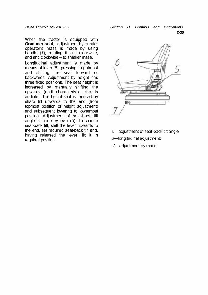
When the tractor is equipped with Grammer seat, adjustment by greater operator’s mass is made by using handle (7), rotating it anti clockwise, and anti clockwise – to smaller mass. Longitudinal adjustment is made by means of lever (6), pressing it rightmost and shifting the seat forward or backwards. Adjustment by height has three fixed positions. The seat height is increased by manually shifting the upwards (until characteristic click is audible). The height seat is reduced by sharp lift upwards to the end (from topmost position of height adjustment) and subsequent lowering to lowermost position. Adjustment of seat-back tilt angle is made by lever (5). To change seat-back tilt, shift the lever upwards to the end, set required seat-back tilt and, having released the lever, fix it in required position.
5—adjustment of seat-back tilt angle
6—longitudinal adjustment;
7—adjustment by mass
Belarus 1025/1025.2/1025.3 Section D. Controls and instruments
D29
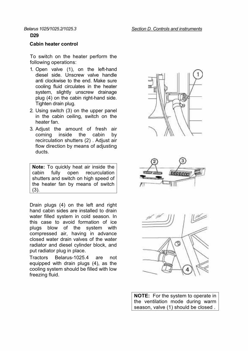
Cabin heater control
To switch on the heater perform the following operations: 1. Open valve (1), on the left-hand
diesel side. Unscrew valve handle anti clockwise to the end. Make sure cooling fluid circulates in the heater system, slightly unscrew drainage plug (4) on the cabin right-hand side. Tighten drain plug.
2. Using switch (3) on the upper panel in the cabin ceiling, switch on the heater fan.
3. Adjust the amount of fresh air coming inside the cabin by recirculation shutters (2) . Adjust air flow direction by means of adjusting ducts.
Note: To quickly heat air inside the cabin fully open recurculation shutters and switch on high speed of the heater fan by means of switch (3).
Drain plugs (4) on the left and right hand cabin sides are installed to drain water filled system in cold season. In this case to avoid formation of ice plugs blow of the system with compressed air, having in advance closed water drain valves of the water radiator and diesel cylinder block, and put radiator plug in place. Tractors Belarus-1025.4 are not equipped with drain plugs (4), as the cooling system should be filled with low freezing fluid.
NOTE: For the system to operate in the ventilation mode during warm season, valve (1) should be closed .
Belarus 1025/1025.2/1025.3 Section D. Controls and instruments D30
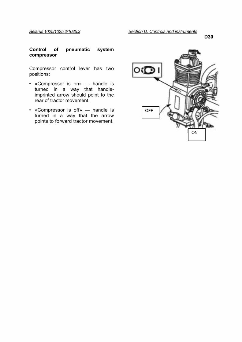
Control of pneumatic system compressor
Compressor control lever has two positions:
• «Compressor is on» — handle is turned in a way that handle-imprinted arrow should point to the rear of tractor movement.
• «Compressor is off» — handle is turned in a way that the arrow points to forward tractor movement.
OFF
ON
Belarus 1025/1025.2/1025.3 Section E.Tractor preparation for operation
E1
Section E. Preparation of tractor for operation
Before putting new tractor in operation perform the following procedures: • wash the tractor; • remove protective PCV sheathes; • carefully examine the tractor, check it for completeness, take off storage batteries, bring the to operational state and put in place; • put in place drain radiator and diesel cylinder block valves attached to tractor and stored in a separate instruments’ box; • check tightness of threaded connections and tighten them, if needed; • unpack the muffler, placed in the tractor cabin and install it on the exhaust manifold with outlet cut directed forward to tractor movement. Put tightening hose at the distance of 8…12 mm away from the muffler manifold end face. . Torque nuts to 44…56 Nm.
• check oil pressure in diesel casing, transmission, FDA case, end drives’ reduction gears, oil tanks of the hydraulic systems and HS, and fill it up, if required; • drain remaining fuel from fuel tanks and refill them with settled fresh fuel : winder grade in cold season and summer grade in summer; • refill the diesel cooling system with cooling fluid up to upper end face of the filling neck; • check and, if necessary, adjust tension of the generator belt; • grease tractor mechanisms and assemblies in accordance with directions of the present operation manual; • check and, if necessary, bring to norm tires’ pressure.
ATTENTION! Before putting the tractor into operation check if protective fencing shields (rear PTO end drives, etc.) are available.).
PREPARATION FOR START AND DIESEL START
Start at normal conditions (+4°С and above) IMPORTANT! Start the diesel and check instruments’ operation only being on the operator’s seat.
IMPORTANT! Never start the diesel with the cooling system not filled up!
• Engage tractor parking brake; • Open fuel tank cock; Tractors with hydraulic lift are not provided with the cock.
Fill up and bleed the fuel supply system to remove air. • Set fuel supply control levers to the
middle position , and PTO control lever to position “Switched off”;
• Set gear and range shifting levers to neutral position;
• Switch on “ground”; • Turn starter switch to position «I»
(fixed). The lamp of emergency HS oil pressure in the box of control lamps should light.
Belarus 1025/1025.2/1025.3 Section E. Preparation for operation
E2 And in the flashing mode with 1 Hz
frequency the control lamp of the parking brake alarm, and in combination of instruments: the lamp of emergency diesel oil pressure (the buzzer is audible), air pressure indicator (if it is lower of the allowable limit), voltage indicator and fuel level indicator (if fuel in tanks is on the reserve level);
• Put starter switch key to position«II» («Start»).
• Hold the key until diesel is started, but for not more than 15 seconds. If diesel doesn’t start, repeated start make not earlier than 30…40 seconds. If after three attempts diesel doesn’t start, find out the cause and correct it.
• After starting the diesel check functioning of all indicating lamps and instruments’ readings (cooling fluid temperature, oil pressure in diesel and GB, storage batteries’ charging, etc.) Let diesel operate at 1000 rev/min until pressure within operation range gets stable.
• Control lamp of the second SB charging should go down after diesel start. It means that the second 24 V voltage SB is being charged by means of the voltage converter. If charging control lamp is still on after diesel start, it means that the second battery is not being charged, and the cause has to be found and corrected. .
IMPORTANT! Your tractor is equipped with turbo supercharged diesel. High turbo supercharger revolutions require proper lubrication during diesel start. When starting diesel after prolonged storage, use starter to rotate the crankshaft for about 10 seconds without fuel supply to provide lubrication of turbo supercharger bearings. Let diesel operate idle for 2…3 minutes before loading it.
Starting at low temperatures (+4°С and below) 1. Diesel is equipped with electric torch heater
Important! To avoid damage of power gear, do not push or tow tractor to start diesel.
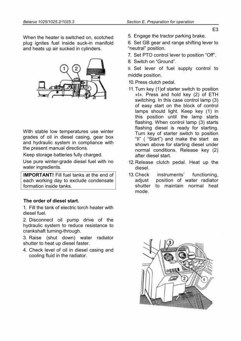
Electric torch heater is efficient in the ambient temperature range of from +4°С to - 20°С. It consists of tank (1) with diesel fuel and heating element (2) (spark plug, electromagnetic valve and nozzle). .
Never use ether substances to make start easier when electric torch heater is installed. The use of ether may lead to explosion in the inlet manifold and serious injury or mutilation. When ether means are used to make start easier, disconnect and insulate wiring of the electric torch heater, installed on the suck-in diesel manifold.
Belarus 1025/1025.2/1025.3 Section E. Preparation for operation
When the heater is switched on, scotched plug ignites fuel inside suck-in manifold and heats up air sucked in cylinders.
With stable low temperatures use winter grades of oil in diesel casing, gear box and hydraulic system in compliance with the present manual directions. Keep storage batteries fully charged. Use pure winter-grade diesel fuel with no water ingredients. IMPORTANT! Fill fuel tanks at the end of each working day to exclude condensate formation inside tanks.
The order of diesel start. 1. Fill the tank of electric torch heater with diesel fuel. 2. Disconnect oil pump drive of the hydraulic system to reduce resistance to crankshaft turning-through. 3. Raise (shut down) water radiator shutter to heat up diesel faster. 4. Check level of oil in diesel casing and
cooling fluid in the radiator.
E3 5. Engage the tractor parking brake. 6. Set GB gear and range shifting lever to “neutral” position. 7. Set PTO control lever to position “Off”. 8. Switch on “Ground”. 9. Set lever of fuel supply control to middle position. 10. Press clutch pedal. 11. Turn key (1)of starter switch to position
«I». Press and hold key (2) of ETH switching. In this case control lamp (3) of easy start on the block of control lamps should light. Keep key (1) in this position until the lamp starts flashing. When control lamp (3) starts flashing diesel is ready for starting. Turn key of starter switch to position “II” ( “Start”) and make the start as shown above for starting diesel under normal conditions. Release key (2) after diesel start.
12. Release clutch pedal. Heat up the diesel.
13. Check instruments’ functioning, adjust position of water radiator shutter to maintain normal heat mode.
Belarus 1025/1025.2/1025.3 Section E. Preparation for operation
E4
2. Diesel is equipped with incandescent plugs. • Perform operations 1 - 10 from section "The order of diesel start". • Keep the key in position “I” for more than 2 seconds. In this case easy start control lamp lights to indicate switching on of incandescent plug. Keep the key in this position . As soon as control lamp starts flashing, diesel is ready for start. • Turn key of starter switch to position “II” and make start as shown above for diesel start under normal conditions.
After diesel start control lamp goes down and sound alarm is switched off. • Perform operations 12 and 13 from section "The order of diesel start”.
If the control lamp lights in the interrupted mode with frequency of 2 Hz after diesel start for 3 minutes, it means that terminals of incandescent plugs relay are wrong. Shut down the diesel, disconnect ground switch and correct malfunction. .
Starting off and movement of tractor
Note: When selecting required movement speed, use the table of movement speed, given in section “C”
• Disengage the parking brake, smoothly release the clutch pedal and increase diesel rotation speed, the tractor will start movement.
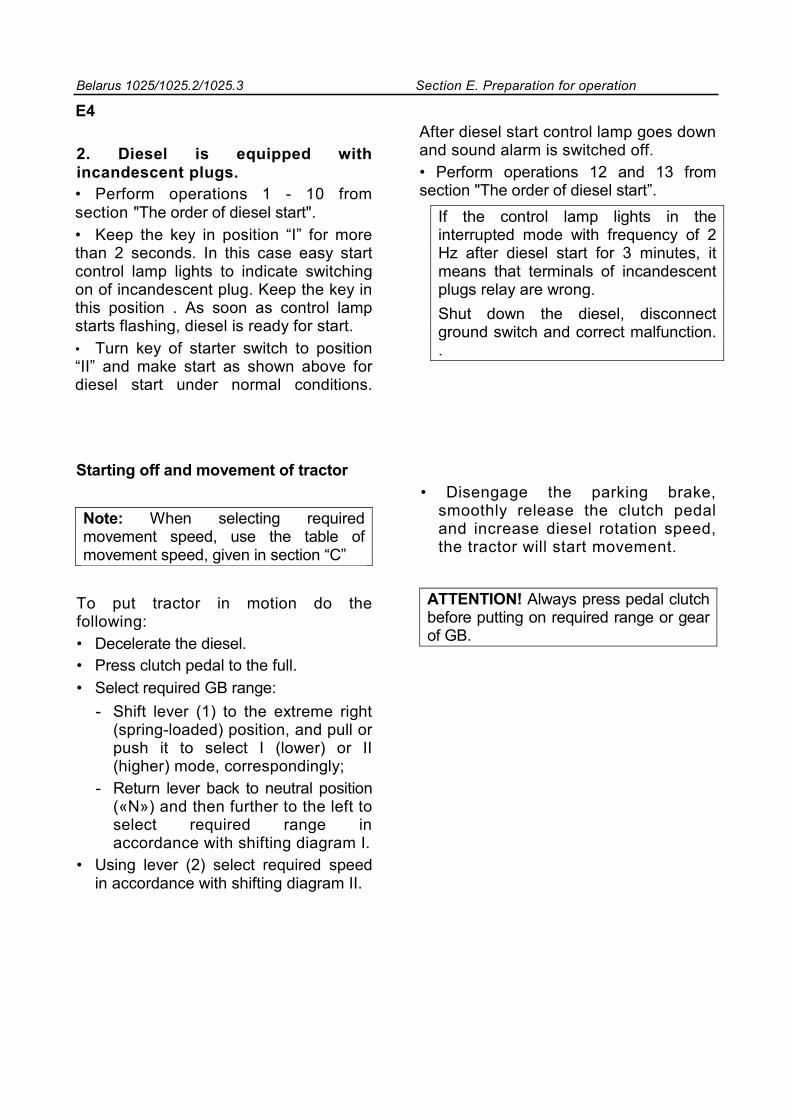
To put tractor in motion do the following: • Decelerate the diesel. • Press clutch pedal to the full. • Select required GB range:
- Shift lever (1) to the extreme right (spring-loaded) position, and pull or push it to select I (lower) or II (higher) mode, correspondingly;
- Return lever back to neutral position («N») and then further to the left to select required range in accordance with shifting diagram I.
• Using lever (2) select required speed in accordance with shifting diagram II.
ATTENTION! Always press pedal clutch before putting on required range or gear of GB.
Belarus 1025/1025.2/1025.3 Section E. Preparation for operation
E5
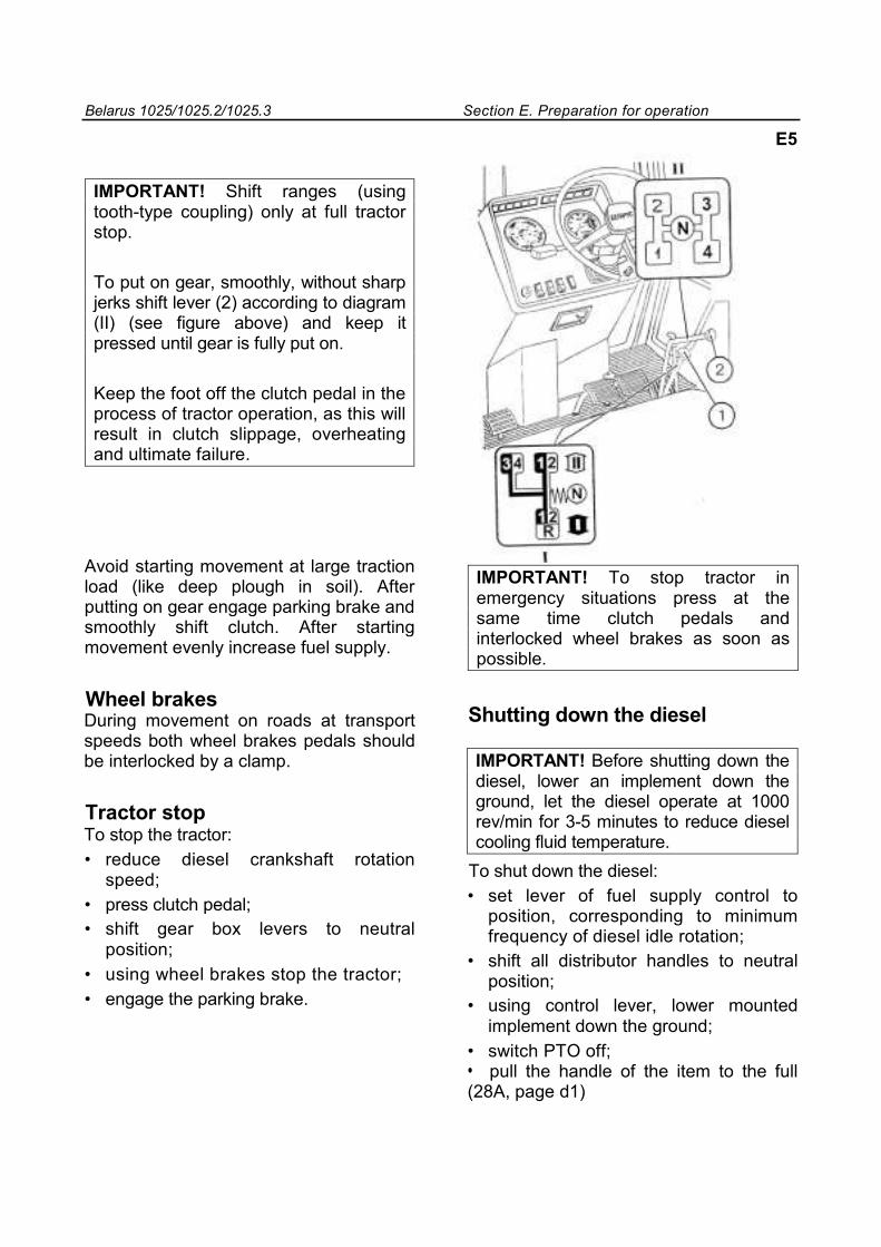
IMPORTANT! Shift ranges (using tooth-type coupling) only at full tractor stop.
To put on gear, smoothly, without sharp jerks shift lever (2) according to diagram (II) (see figure above) and keep it pressed until gear is fully put on.
Keep the foot off the clutch pedal in the process of tractor operation, as this will result in clutch slippage, overheating and ultimate failure.
Avoid starting movement at large traction load (like deep plough in soil). After putting on gear engage parking brake and smoothly shift clutch. After starting movement evenly increase fuel supply.
Wheel brakes During movement on roads at transport speeds both wheel brakes pedals should be interlocked by a clamp.
Tractor stop To stop the tractor: • reduce diesel crankshaft rotation
speed; • press clutch pedal; • shift gear box levers to neutral
position; • using wheel brakes stop the tractor; • engage the parking brake.
IMPORTANT! To stop tractor in emergency situations press at the same time clutch pedals and interlocked wheel brakes as soon as possible.
Shutting down the diesel
IMPORTANT! Before shutting down the diesel, lower an implement down the ground, let the diesel operate at 1000 rev/min for 3-5 minutes to reduce diesel cooling fluid temperature.
To shut down the diesel: • set lever of fuel supply control to
position, corresponding to minimum frequency of diesel idle rotation;
• shift all distributor handles to neutral position;
• using control lever, lower mounted implement down the ground;
• switch PTO off; • pull the handle of the item to the full (28A, page d1)

Belarus 1025/1025.2/1025.3 Рsection E. Preparation for operation
E6
• switch “the ground” off
IMPORTANT! Tractor Belarus is equipped with hydraulic-volumetric steering. If diesel is shut down the oil pump driven by diesel crankshaft , doesn’t supply HS hydraulic system and it automatically is transferred to the manual steering mode, that requires greater force applied to the steering wheel to turn the tractor.
Running - in
IMPORTANT! The first thirty hours of tractor operation have great impact on operation parameters and life of the tractor, and its diesel in particular.
Your new tractor will demonstrate reliable and long-term operation on condition it is properly run-in and all required service operations are performed in recommended periods. IMPORTANT! The first fifteen hours of operation should be spent on light transport works, and the remaining running-in time – on light field works using HMS.
The signs of overload are drastic drop of revolutions, smoking and absence of diesel response to increase of fuel supply. Operation at high gear under load leads to excessive wear of diesel friction parts. 4. Operation of tractor at too low gear with small load and at high diesel revolutions will cause over consumption of fuel. Correct choice of the gear for each concrete operation mode saves fuel and reduces diesel wear.
During 30-hours’ running-in observe the following precautionary measures: 1. Monitor instruments’ readings, lubrication
system, cooling and power supply operation. Check level of fluids and oil in filling reservoirs.
2. Check tightness of outside fastening connections.
3. Do not overload the diesel, do not allow smoking drastic drop of revolutions.
Belarus 1025/1025.2/1025.3 Section E. Preparation for operation
5. Run-in the tractor during easy works (sowing, cultivation, grass cutting, transport). Load diesel by not more than 50% of the rated power.
6. Avoid prolonged operation without load in conditions of maximum or minimum diesel speed.
7. Avoid prolonged tractor operation in conditions of permanent diesel speed.
8. To guarantee correct alignment of clutch friction parts during run-in, engage the clutch more frequently and smoothly.
9. Make regular daily maintenance in compliance with recommendations set forth in the present instruction manual.
Upon completion of 30-hours’ run-in perform maintenance operations according to directions set forth in section G “Scheduled maintenance”, page G6.
Warning: To avoid injuries, before starting diesel make sure all protective fencing is in its proper place.
E7
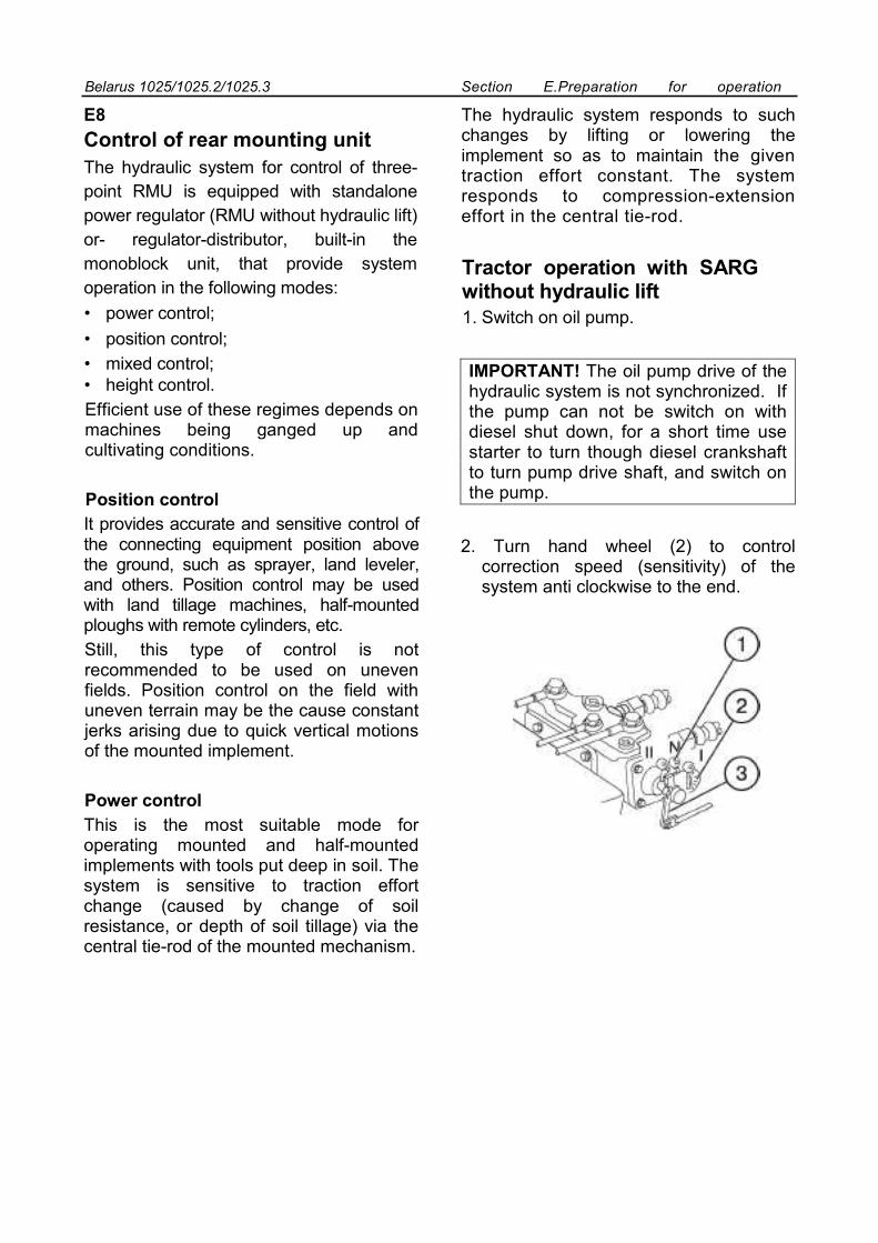
Belarus 1025/1025.2/1025.3 Section E.Preparation for operation
E8
Control of rear mounting unit The hydraulic system for control of three-point RMU is equipped with standalone power regulator (RMU without hydraulic lift) or- regulator-distributor, built-in the monoblock unit, that provide system operation in the following modes: • power control; • position control; • mixed control; • height control. Efficient use of these regimes depends on machines being ganged up and cultivating conditions.
Position control It provides accurate and sensitive control of the connecting equipment position above the ground, such as sprayer, land leveler, and others. Position control may be used with land tillage machines, half-mounted ploughs with remote cylinders, etc. Still, this type of control is not recommended to be used on uneven fields. Position control on the field with uneven terrain may be the cause constant jerks arising due to quick vertical motions of the mounted implement.
Power control This is the most suitable mode for operating mounted and half-mounted implements with tools put deep in soil. The system is sensitive to traction effort change (caused by change of soil resistance, or depth of soil tillage) via the central tie-rod of the mounted mechanism.
The hydraulic system responds to such changes by lifting or lowering the implement so as to maintain the given traction effort constant. The system responds to compression-extension effort in the central tie-rod.
Tractor operation with SARG without hydraulic lift
1. Switch on oil pump.
IMPORTANT! The oil pump drive of the hydraulic system is not synchronized. If the pump can not be switch on with diesel shut down, for a short time use starter to turn though diesel crankshaft to turn pump drive shaft, and switch on the pump.
2. Turn hand wheel (2) to control correction speed (sensitivity) of the system anti clockwise to the end.
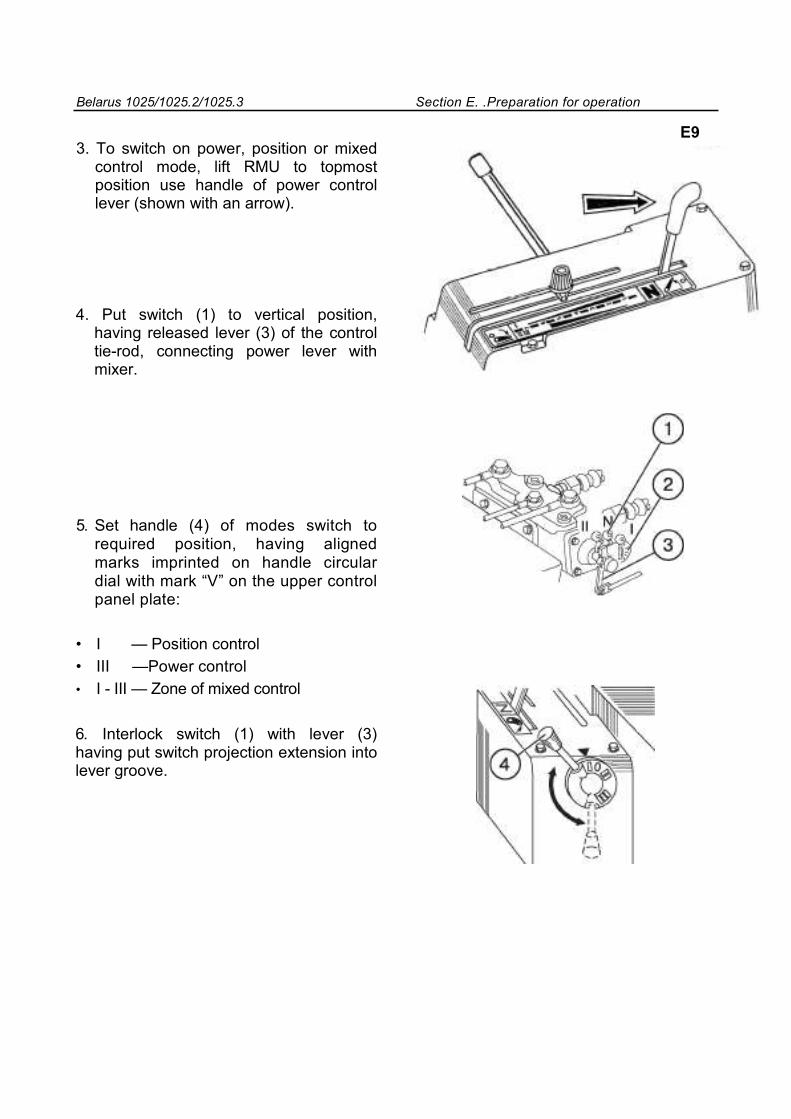
Belarus 1025/1025.2/1025.3 Section E. .Preparation for operation
3. To switch on power, position or mixed control mode, lift RMU to topmost position use handle of power control lever (shown with an arrow).
4. Put switch (1) to vertical position, having released lever (3) of the control tie-rod, connecting power lever with mixer.
5. Set handle (4) of modes switch to required position, having aligned marks imprinted on handle circular dial with mark “V” on the upper control panel plate:
• I — Position control • III —Power control • I - III — Zone of mixed control
6. Interlock switch (1) with lever (3) having put switch projection extension into lever groove.
E9
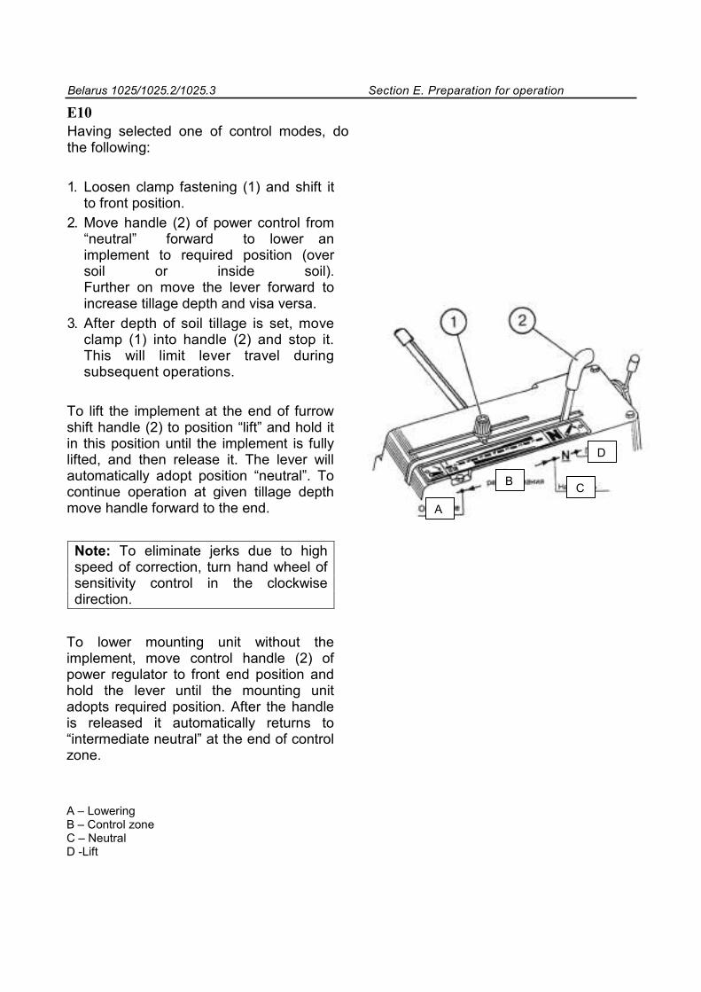
Belarus 1025/1025.2/1025.3 Section E. Preparation for operation
E10 Having selected one of control modes, do the following:
1. Loosen clamp fastening (1) and shift it to front position.
2. Move handle (2) of power control from “neutral” forward to lower an implement to required position (over soil or inside soil). Further on move the lever forward to increase tillage depth and visa versa.
3. After depth of soil tillage is set, move clamp (1) into handle (2) and stop it. This will limit lever travel during subsequent operations.
To lift the implement at the end of furrow shift handle (2) to position “lift” and hold it in this position until the implement is fully lifted, and then release it. The lever will automatically adopt position “neutral”. To continue operation at given tillage depth move handle forward to the end.
Note: To eliminate jerks due to high speed of correction, turn hand wheel of sensitivity control in the clockwise direction.
To lower mounting unit without the implement, move control handle (2) of power regulator to front end position and hold the lever until the mounting unit adopts required position. After the handle is released it automatically returns to “intermediate neutral” at the end of control zone.
A – Lowering B – Control zone C – Neutral D -Lift
A
B C
D
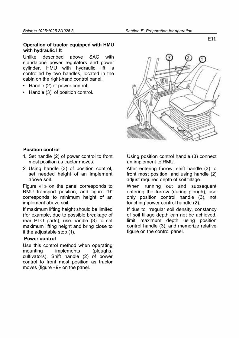
Belarus 1025/1025.2/1025.3 Section E. Preparation for operation
Operation of tractor equipped with HMU with hydraulic lift Unlike described above SAC with standalone power regulators and power cylinder, HMU with hydraulic lift is controlled by two handles, located in the cabin on the right-hand control panel. • Handle (2) of power control; • Handle (3) of position control.
E11
Position control 1. Set handle (2) of power control to front
most position as tractor moves. 2. Using handle (3) of position control,
set needed height of an implement above soil.
Figure «1» on the panel corresponds to RMU transport position, and figure “9” corresponds to minimum height of an implement above soil. If maximum lifting height should be limited (for example, due to possible breakage of rear PTO parts), use handle (3) to set maximum lifting height and bring close to it the adjustable stop (1). Power control Use this control method when operating mounting implements (ploughs, cultivators). Shift handle (2) of power control to front most position as tractor moves (figure «9» on the panel.
Using position control handle (3) connect an implement to RMU. After entering furrow, shift handle (3) to front most position, and using handle (2) adjust required depth of soil tillage. When running out and subsequent entering the furrow (during plough), use only position control handle (3), not touching power control handle (2). If due to irregular soil density, constancy of soil tillage depth can not be achieved, limit maximum depth using position control handle (3), and memorize relative figure on the control panel.
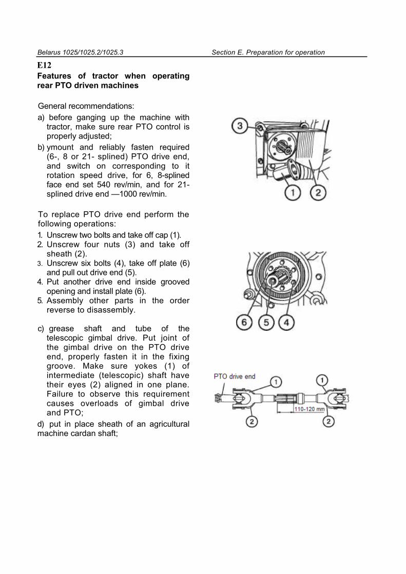
Belarus 1025/1025.2/1025.3 Section E. Preparation for operation
E12 Features of tractor when operating rear PTO driven machines
General recommendations: а) before ganging up the machine with
tractor, make sure rear PTO control is properly adjusted;
b) уmount and reliably fasten required (6-, 8 or 21- splined) PTO drive end, and switch on corresponding to it rotation speed drive, for 6, 8-splined face end set 540 rev/min, and for 21-splined drive end —1000 rev/min.
To replace PTO drive end perform the following operations: 1. Unscrew two bolts and take off cap (1). 2. Unscrew four nuts (3) and take off
sheath (2). 3. Unscrew six bolts (4), take off plate (6)
and pull out drive end (5). 4. Put another drive end inside grooved
opening and install plate (6). 5. Assembly other parts in the order
reverse to disassembly.
c) grease shaft and tube of the telescopic gimbal drive. Put joint of the gimbal drive on the PTO drive end, properly fasten it in the fixing groove. Make sure yokes (1) of intermediate (telescopic) shaft have their eyes (2) aligned in one plane. Failure to observe this requirement causes overloads of gimbal drive and PTO;
d) put in place sheath of an agricultural machine cardan shaft;
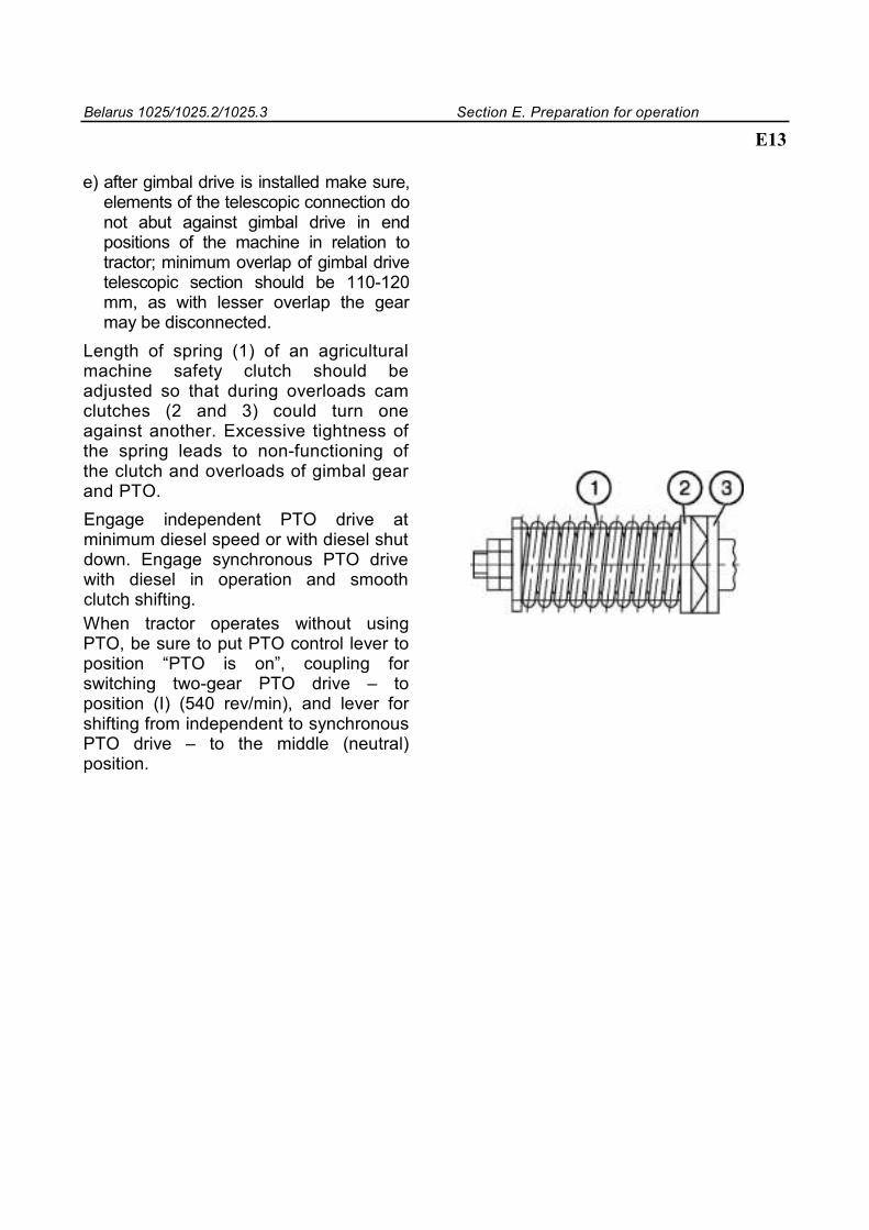
Belarus 1025/1025.2/1025.3 Section E. Preparation for operation
E13
e) after gimbal drive is installed make sure, elements of the telescopic connection do not abut against gimbal drive in end positions of the machine in relation to tractor; minimum overlap of gimbal drive telescopic section should be 110-120 mm, as with lesser overlap the gear may be disconnected.
Length of spring (1) of an agricultural machine safety clutch should be adjusted so that during overloads cam clutches (2 and 3) could turn one against another. Excessive tightness of the spring leads to non-functioning of the clutch and overloads of gimbal gear and PTO. Engage independent PTO drive at minimum diesel speed or with diesel shut down. Engage synchronous PTO drive with diesel in operation and smooth clutch shifting. When tractor operates without using PTO, be sure to put PTO control lever to position “PTO is on”, coupling for switching two-gear PTO drive – to position (I) (540 rev/min), and lever for shifting from independent to synchronous PTO drive – to the middle (neutral) position.
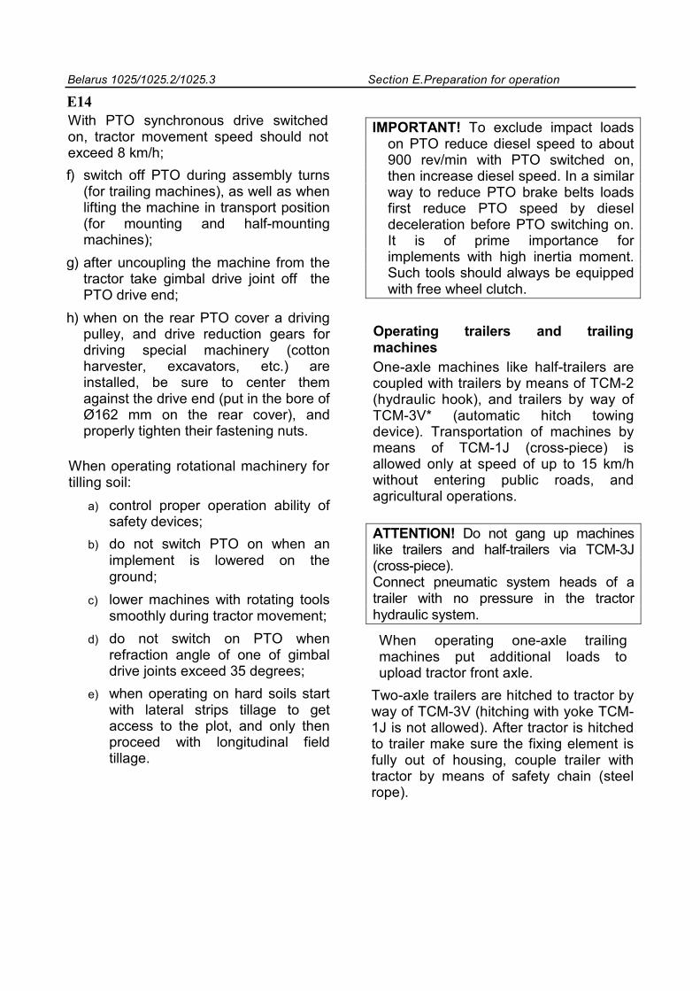
Belarus 1025/1025.2/1025.3 Section E.Preparation for operation
E14 With PTO synchronous drive switched on, tractor movement speed should not exceed 8 km/h; f) switch off PTO during assembly turns
(for trailing machines), as well as when lifting the machine in transport position (for mounting and half-mounting machines);
g) after uncoupling the machine from the tractor take gimbal drive joint off the PTO drive end;
h) when on the rear PTO cover a driving pulley, and drive reduction gears for driving special machinery (cotton harvester, excavators, etc.) are installed, be sure to center them against the drive end (put in the bore of Ø162 mm on the rear cover), and properly tighten their fastening nuts.
When operating rotational machinery for tilling soil:
a) control proper operation ability of safety devices;
b) do not switch PTO on when an implement is lowered on the ground;
c) lower machines with rotating tools smoothly during tractor movement;
d) do not switch on PTO when refraction angle of one of gimbal drive joints exceed 35 degrees;
e) when operating on hard soils start with lateral strips tillage to get access to the plot, and only then proceed with longitudinal field tillage.
IMPORTANT! To exclude impact loads on PTO reduce diesel speed to about 900 rev/min with PTO switched on, then increase diesel speed. In a similar way to reduce PTO brake belts loads first reduce PTO speed by diesel deceleration before PTO switching on. It is of prime importance for implements with high inertia moment. Such tools should always be equipped with free wheel clutch.
Operating trailers and trailing machines One-axle machines like half-trailers are coupled with trailers by means of TCM-2 (hydraulic hook), and trailers by way of TCM-3V* (automatic hitch towing device). Transportation of machines by means of TCM-1J (cross-piece) is allowed only at speed of up to 15 km/h without entering public roads, and agricultural operations. ATTENTION! Do not gang up machines like trailers and half-trailers via TCM-3J (cross-piece). Connect pneumatic system heads of a trailer with no pressure in the tractor hydraulic system.
When operating one-axle trailing machines put additional loads to upload tractor front axle.
Two-axle trailers are hitched to tractor by way of TCM-3V (hitching with yoke TCM-1J is not allowed). After tractor is hitched to trailer make sure the fixing element is fully out of housing, couple trailer with tractor by means of safety chain (steel rope).
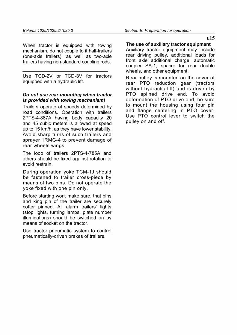
Belarus 1025/1025.2/1025.3 Section E. Preparation for operation
When tractor is equipped with towing mechanism, do not couple to it half-trailers (one-axle trailers), as well as two-axle trailers having non-standard coupling rods.
Use ТСD-2V or ТСD-ЗV for tractors equipped with a hydraulic lift.
Do not use rear mounting when tractor is provided with towing mechanism! Trailers operate at speeds determined by road conditions. Operation with trailers 2PTS-4-887A having body capacity 20 and 45 cubic meters is allowed at speed up to 15 km/h, as they have lower stability. Avoid sharp turns of such trailers and sprayer 1RMG-4 to prevent damage of rear wheels wings. The loop of trailers 2PTS-4-785A and others should be fixed against rotation to avoid restrain. During operation yoke TCM-1J should be fastened to trailer cross-piece by means of two pins. Do not operate the yoke fixed with one pin only. Before starting work make sure, that pins and king pin of the trailer are securely cotter pinned. All alarm trailers’ lights (stop lights, turning lamps, plate number illuminations) should be switched on by means of socket on the tractor. Use tractor pneumatic system to control pneumatically-driven brakes of trailers.
E15 The use of auxiliary tractor equipment Auxiliary tractor equipment may include rear driving pulley, additional loads for front axle additional charge, automatic coupler SA-1, spacer for rear double wheels, and other equipment. Rear pulley is mounted on the cover of rear PTO reduction gear (tractors without hydraulic lift) and is driven by PTO splined drive end. To avoid deformation of PTO drive end, be sure to mount the housing using four pin and flange centering in PTO cover. Use PTO control lever to switch the pulley on and off.
Belarus 1025/1025.2/1025.3 Section F. Ganging up
Section F GANGING UP
Ganging up of tractors includes a set of works, related to selection of machines, determination of possibility and technology of their coupling to tractors, setting and adjustment of mechanisms of all machine-tractor assembly (MTA) elements. Tractor is ganged up to the following types of agricultural machines and implements; • mounted – coupled to three-point tractor mounting unit. In transport position machine mass is fully taken by tractor; • Half-mounted - are coupled to three-point tractor mounting unit and have support wheels. In transport position machine mass is partly taken by tractor, and partly – by own wheels. When transferring machine from operation position to transport position, coupling point is shifted by force to new position by height. • Half-trailers - are coupled to three-point mounting unit or traction-coupling mechanism of tractor. In transport position machine mass is partly taken by tractor and partly – by own wheels. When transferring machine from operation to transport position, coupling point doesn’t change its position by height. • • trailers – are coupled to traction-coupling tractor device. In transport position machine mass is taken its chassis. When transferring machine from operation to transport position the joint connected to tractor doesn’t change its position by height
F1 ATTENTION! 1. The manufacturer guarantees reliable tractor operation in full completeness when used as part of different agricultural machine-tractor assemblies, composed of standard ganging up system (mounting unit, traction-coupling mechanisms) as a power unit. 2. The use of mounted machines (machine mass is fully taken by tractor: excavators, loaders, etc.) for coupling of which tractor openings and additional assembly units are used, is non-standard way of ganging up. When machines not agreed with manufacturer are mounted, consumers’ claims should be accepted by organizations, which erected and checked equipment. Tractor operates with all machines, which comply with its technical characteristics in power, mass, coupling and dimensional size. The present section deals with data on operation equipment for ganging up, methodology of selecting machines for these tractors, rated values of loading and speed modes of tractor as part of MTA.
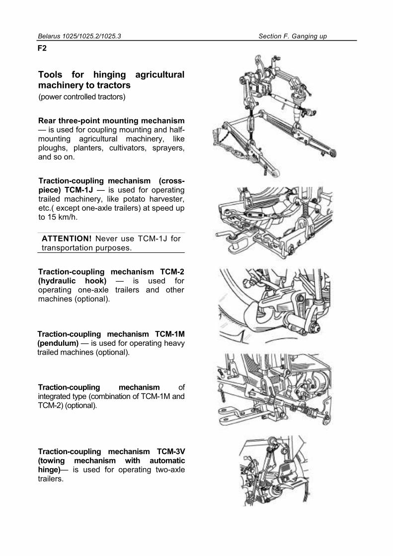
Belarus 1025/1025.2/1025.3 Section F. Ganging up
F2
Tools for hinging agricultural machinery to tractors
(power controlled tractors)
Rear three-point mounting mechanism — is used for coupling mounting and half-mounting agricultural machinery, like ploughs, planters, cultivators, sprayers, and so on.
Traction-coupling mechanism (cross-piece) TCM-1J — is used for operating trailed machinery, like potato harvester, etc.( except one-axle trailers) at speed up to 15 km/h.
ATTENTION! Never use TCM-1J for transportation purposes.
Traction-coupling mechanism TCM-2 (hydraulic hook) — is used for operating one-axle trailers and other machines (optional).
Traction-coupling mechanism TCM-1M (pendulum) — is used for operating heavy trailed machines (optional).
Traction-coupling mechanism of integrated type (combination of TCM-1M and TCM-2) (optional).
Traction-coupling mechanism TCM-3V (towing mechanism with automatic hinge)— is used for operating two-axle trailers.
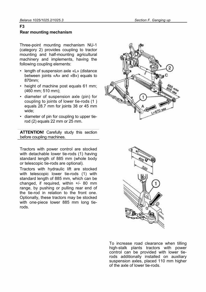
Belarus 1025/1025.2/1025.3 Section F. Ganging up
F3 Rear mounting mechanism
Three-point mounting mechanism NU-1 (category 2) provides coupling to tractor mounting and half-mounting agricultural machinery and implements, having the following coupling elements: • length of suspension axle «L» (distance
between joints «А» and «В») equals to 870mm;
• height of machine post equals 61 mm; (460 mm; 510 mm);
• diameter of suspension axle (pin) for coupling to joints of lower tie-rods (1 ) equals 28.7 mm for joints 38 or 45 mm wide;
• diameter of pin for coupling to upper tie-rod (2) equals 22 mm or 25 mm.
ATTENTION! Carefully study this section before coupling machines.
Tractors with power control are stocked with detachable lower tie-rods (1) having standard length of 885 mm (whole body or telescopic tie-rods are optional). Tractors with hydraulic lift are stocked with telescopic lower tie-rods (1) with standard length of 885 mm, which can be changed, if required, within +/- 80 mm range, by pushing or pulling rear end of the tie-rod in relation to the front one. Optionally, these tractors may be stocked with one-piece lower 885 mm long tie-rods.
To increase road clearance when tilling high-stalk plants tractors with power control can be provided with lower tie-rods additionally installed on auxiliary suspension axles, placed 110 mm higher of the axle of lower tie-rods.
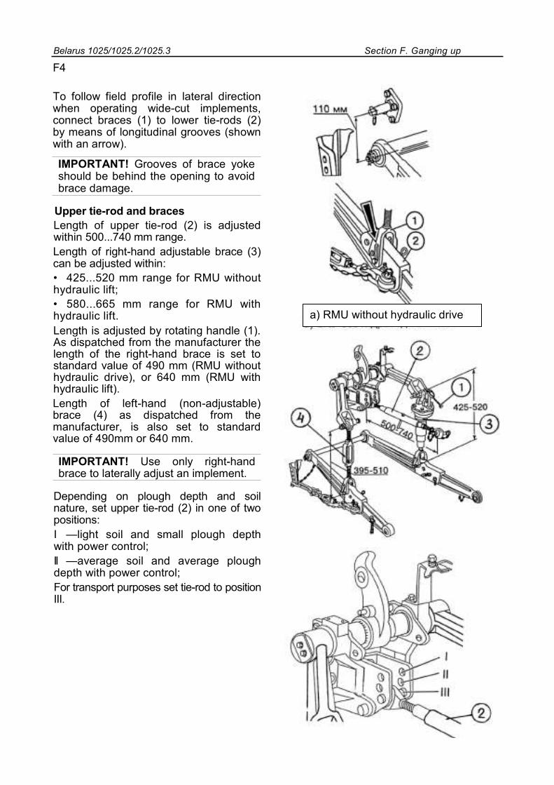
Belarus 1025/1025.2/1025.3 Section F. Ganging up
F4 To follow field profile in lateral direction when operating wide-cut implements, connect braces (1) to lower tie-rods (2) by means of longitudinal grooves (shown with an arrow).
IMPORTANT! Grooves of brace yoke should be behind the opening to avoid brace damage.
Upper tie-rod and braces Length of upper tie-rod (2) is adjusted within 500...740 mm range. Length of right-hand adjustable brace (3) can be adjusted within: • 425...520 mm range for RMU without hydraulic lift; • 580...665 mm range for RMU with hydraulic lift. Length is adjusted by rotating handle (1). As dispatched from the manufacturer the length of the right-hand brace is set to standard value of 490 mm (RMU without hydraulic drive), or 640 mm (RMU with hydraulic lift). Length of left-hand (non-adjustable) brace (4) as dispatched from the manufacturer, is also set to standard value of 490mm or 640 mm.
IMPORTANT! Use only right-hand brace to laterally adjust an implement.
Depending on plough depth and soil nature, set upper tie-rod (2) in one of two positions: I —light soil and small plough depth with power control; II —average soil and average plough depth with power control; For transport purposes set tie-rod to position III.
a) RMU without hydraulic drive
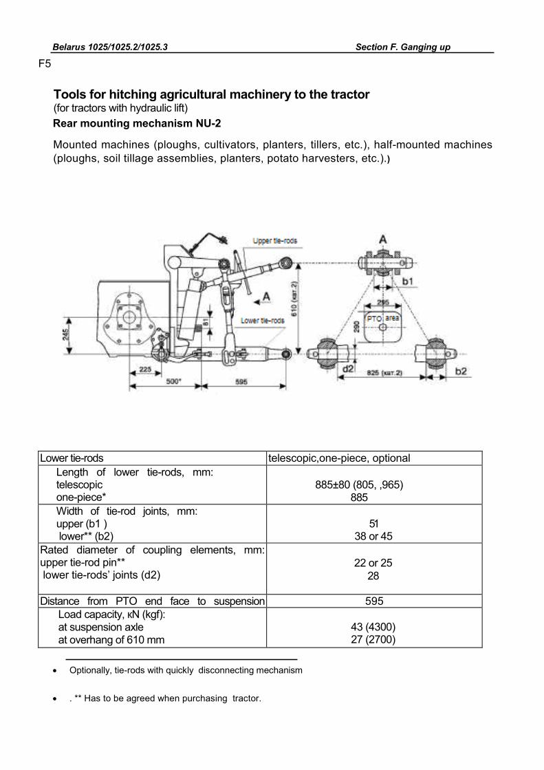
Belarus 1025/1025.2/1025.3 Section F. Ganging up
F5
Tools for hitching agricultural machinery to the tractor (for tractors with hydraulic lift) Rear mounting mechanism NU-2
Mounted machines (ploughs, cultivators, planters, tillers, etc.), half-mounted machines (ploughs, soil tillage assemblies, planters, potato harvesters, etc.).)
Lower tie-rods telescopic,one-piece, optional Length of lower tie-rods, mm: telescopic one-piece*
885±80 (805, ,965)
885 Width of tie-rod joints, mm: upper (b1 ) lower** (b2)
51
38 or 45 Rated diameter of coupling elements, mm: upper tie-rod pin** lower tie-rods’ joints (d2)
22 or 25
28
Distance from PTO end face to suspension
595 Load capacity, кN (kgf): at suspension axle at overhang of 610 mm
43 (4300) 27 (2700)
• Optionally, tie-rods with quickly disconnecting mechanism
• . ** Has to be agreed when purchasing tractor.
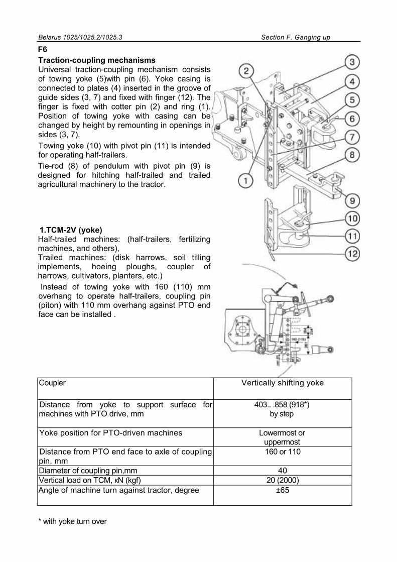
Belarus 1025/1025.2/1025.3 Section F. Ganging up
F6 Traction-coupling mechanisms Universal traction-coupling mechanism consists of towing yoke (5)with pin (6). Yoke casing is connected to plates (4) inserted in the groove of guide sides (3, 7) and fixed with finger (12). The finger is fixed with cotter pin (2) and ring (1). Position of towing yoke with casing can be changed by height by remounting in openings in sides (3, 7). Towing yoke (10) with pivot pin (11) is intended for operating half-trailers. Tie-rod (8) of pendulum with pivot pin (9) is designed for hitching half-trailed and trailed agricultural machinery to the tractor. 1.TCM-2V (yoke) Half-trailed machines: (half-trailers, fertilizing machines, and others), Trailed machines: (disk harrows, soil tilling implements, hoeing ploughs, coupler of harrows, cultivators, planters, etc.) Instead of towing yoke with 160 (110) mm overhang to operate half-trailers, coupling pin (piton) with 110 mm overhang against PTO end face can be installed .
Coupler Vertically shifting yoke
Distance from yoke to support surface for machines with PTO drive, mm
403.. .858 (918*) by step
Yoke position for PTO-driven machines Lowermost or uppermost
Distance from PTO end face to axle of coupling pin, mm
160 or 110
Diameter of coupling pin,mm 40 Vertical load on TCM, кN (kgf) 20 (2000) Angle of machine turn against tractor, degree ±65
* with yoke turn over
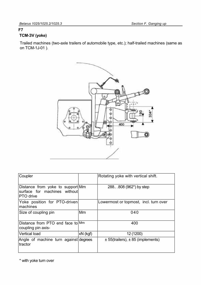
Belarus 1025/1025.2/1025.3 Section F. Ganging up
F7
TCM-ЗV (yoke)
Trailed machines (two-axle trailers of automobile type, etc.); half-trailed machines (same as on TCM-1J-01 ).
Coupler Rotating yoke with vertical shift.
Distance from yoke to support surface for machines without PTO drive
Mm 288.. .808 (962*) by step
Yoke position for PTO-driven machines
Lowermost or topmost, incl. turn over
Size of coupling pin Mm 040
Distance from PTO end face to coupling pin axis-
Mm 400
Vertical load кN (kgf) 12 (1200) Angle of machine turn against tractor
degrees ± 55(trailers), ± 85 (implements)
* with yoke turn over
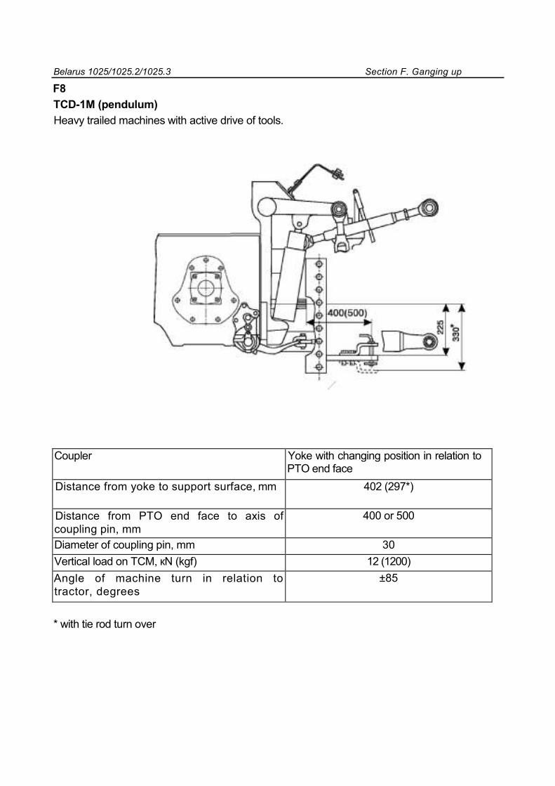
Belarus 1025/1025.2/1025.3 Section F. Ganging up
F8
ТСD-1М (pendulum) Heavy trailed machines with active drive of tools.
Coupler Yoke with changing position in relation to PTO end face
Distance from yoke to support surface, mm 402 (297*)
Distance from PTO end face to axis of coupling pin, mm
400 or 500
Diameter of coupling pin, mm 30
Vertical load on TCM, кN (kgf) 12 (1200) Angle of machine turn in relation to tractor, degrees
±85
* with tie rod turn over
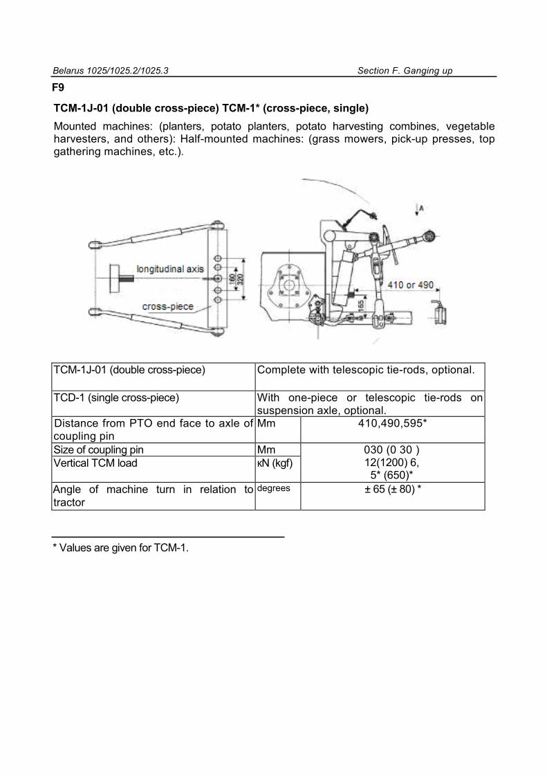
Belarus 1025/1025.2/1025.3 Section F. Ganging up
F9
TCM-1J-01 (double cross-piece) TCM-1* (cross-piece, single) Mounted machines: (planters, potato planters, potato harvesting combines, vegetable harvesters, and others): Half-mounted machines: (grass mowers, pick-up presses, top gathering machines, etc.).
TCM-1J-01 (double cross-piece) Complete with telescopic tie-rods, optional.
ТСD-1 (single cross-piece) With one-piece or telescopic tie-rods on suspension axle, optional.
Distance from PTO end face to axle of coupling pin
Mm 410,490,595*
Size of coupling pin Mm 030 (0 30 ) 12(1200) 6,
5* (650)* Vertical TCM load кN (kgf)
Angle of machine turn in relation to tractor
degrees ± 65 (± 80) *
* Values are given for TCM-1.
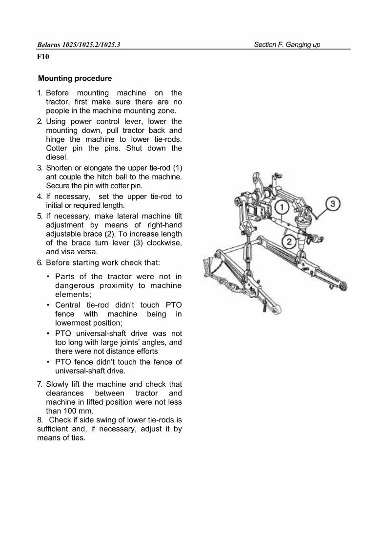
Belarus 1025/1025.2/1025.3 Section F. Ganging up
F10
Mounting procedure
1. Before mounting machine on the tractor, first make sure there are no people in the machine mounting zone.
2. Using power control lever, lower the mounting down, pull tractor back and hinge the machine to lower tie-rods. Cotter pin the pins. Shut down the diesel.
3. Shorten or elongate the upper tie-rod (1) ant couple the hitch ball to the machine. Secure the pin with cotter pin.
4. If necessary, set the upper tie-rod to initial or required length.
5. If necessary, make lateral machine tilt adjustment by means of right-hand adjustable brace (2). To increase length of the brace turn lever (3) clockwise, and visa versa.
6. Before starting work check that:
• Parts of the tractor were not in dangerous proximity to machine elements;
• Central tie-rod didn’t touch PTO fence with machine being in lowermost position;
• PTO universal-shaft drive was not too long with large joints’ angles, and there were not distance efforts
• PTO fence didn’t touch the fence of universal-shaft drive.
7. Slowly lift the machine and check that clearances between tractor and machine in lifted position were not less than 100 mm.
8. Check if side swing of lower tie-rods is sufficient and, if necessary, adjust it by means of ties.
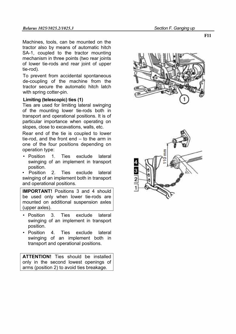
Belarus 1025/1025.2/1025.3 Section F. Ganging up
F11
Machines, tools, can be mounted on the tractor also by means of automatic hitch SA-1, coupled to the tractor mounting mechanism in three points (two rear joints of lower tie-rods and rear joint of upper tie-rod). To prevent from accidental spontaneous de-coupling of the machine from the tractor secure the automatic hitch latch with spring cotter-pin. Limiting (telescopic) ties (1) Ties are used for limiting lateral swinging of the mounting lower tie-rods both in transport and operational positions. It is of particular importance when operating on slopes, close to excavations, walls, etc. Rear end of the tie is coupled to lower tie-rod, and the front end – to the arm in one of the four positions depending on operation type: • Position 1. Ties exclude lateral
swinging of an implement in transport position.
• Position 2. Ties exclude lateral swinging of an implement both in transport and operational positions. IMPORTANT! Positions 3 and 4 should be used only when lower tie-rods are mounted on additional suspension axles (upper axles). • Position 3. Ties exclude lateral
swinging of an implement in transport position.
• Position 4. Ties exclude lateral swinging of an implement both in transport and operational positions.
ATTENTION! Ties should be installed only in the second lowest openings of arms (position 2) to avoid ties breakage.
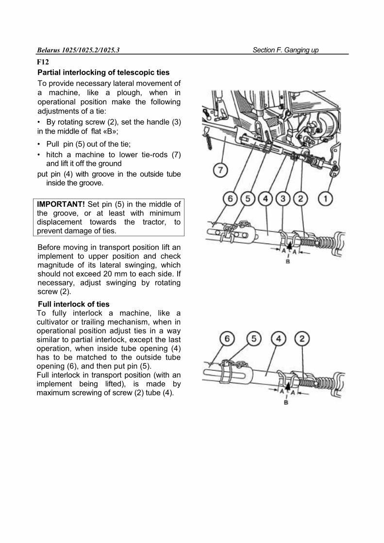
Belarus 1025/1025.2/1025.3 Section F. Ganging up
F12 Partial interlocking of telescopic ties
To provide necessary lateral movement of a machine, like a plough, when in operational position make the following adjustments of a tie: • By rotating screw (2), set the handle (3) in the middle of flat «В»; • Pull pin (5) out of the tie; • hitch a machine to lower tie-rods (7)
and lift it off the ground put pin (4) with groove in the outside tube
inside the groove.
IMPORTANT! Set pin (5) in the middle of the groove, or at least with minimum displacement towards the tractor, to prevent damage of ties.
Before moving in transport position lift an implement to upper position and check magnitude of its lateral swinging, which should not exceed 20 mm to each side. If necessary, adjust swinging by rotating screw (2). Full interlock of ties To fully interlock a machine, like a cultivator or trailing mechanism, when in operational position adjust ties in a way similar to partial interlock, except the last operation, when inside tube opening (4) has to be matched to the outside tube opening (6), and then put pin (5). Full interlock in transport position (with an implement being lifted), is made by maximum screwing of screw (2) tube (4).
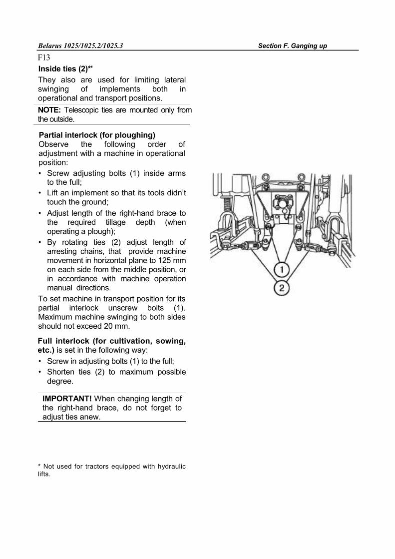
Belarus 1025/1025.2/1025.3 Section F. Ganging up
F13
Inside ties (2)*' They also are used for limiting lateral swinging of implements both in operational and transport positions. NOTE: Telescopic ties are mounted only from the outside.
Partial interlock (for ploughing) Observe the following order of adjustment with a machine in operational position: • Screw adjusting bolts (1) inside arms
to the full; • Lift an implement so that its tools didn’t
touch the ground; • Adjust length of the right-hand brace to
the required tillage depth (when operating a plough);
• By rotating ties (2) adjust length of arresting chains, that provide machine movement in horizontal plane to 125 mm on each side from the middle position, or in accordance with machine operation manual directions.
To set machine in transport position for its partial interlock unscrew bolts (1). Maximum machine swinging to both sides should not exceed 20 mm.
Full interlock (for cultivation, sowing, etc.) is set in the following way: • Screw in adjusting bolts (1) to the full; • Shorten ties (2) to maximum possible
degree.
IMPORTANT! When changing length of the right-hand brace, do not forget to adjust ties anew.
* Not used for tractors equipped with hydraulic lifts.
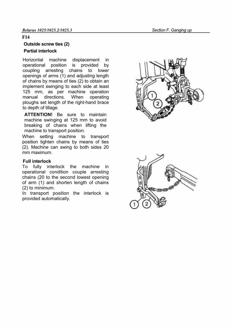
Belarus 1025/1025.2/1025.3 Section F. Ganging up
F14
Outside screw ties (2) Partial interlock
Horizontal machine displacement in operational position is provided by coupling arresting chains to lower openings of arms (1) and adjusting length of chains by means of ties (2) to obtain an implement swinging to each side at least 125 mm, as per machine operation manual directions. When operating ploughs set length of the right-hand brace to depth of tillage. ATTENTION! Be sure to maintain machine swinging at 125 mm to avoid breaking of chains when lifting the machine to transport position.
When setting machine to transport position tighten chains by means of ties (2). Machine can swing to both sides 20 mm maximum.
Full interlock To fully interlock the machine in operational condition couple arresting chains (20 to the second lowest opening of arm (1) and shorten length of chains (2) to minimum. In transport position the interlock is provided automatically.
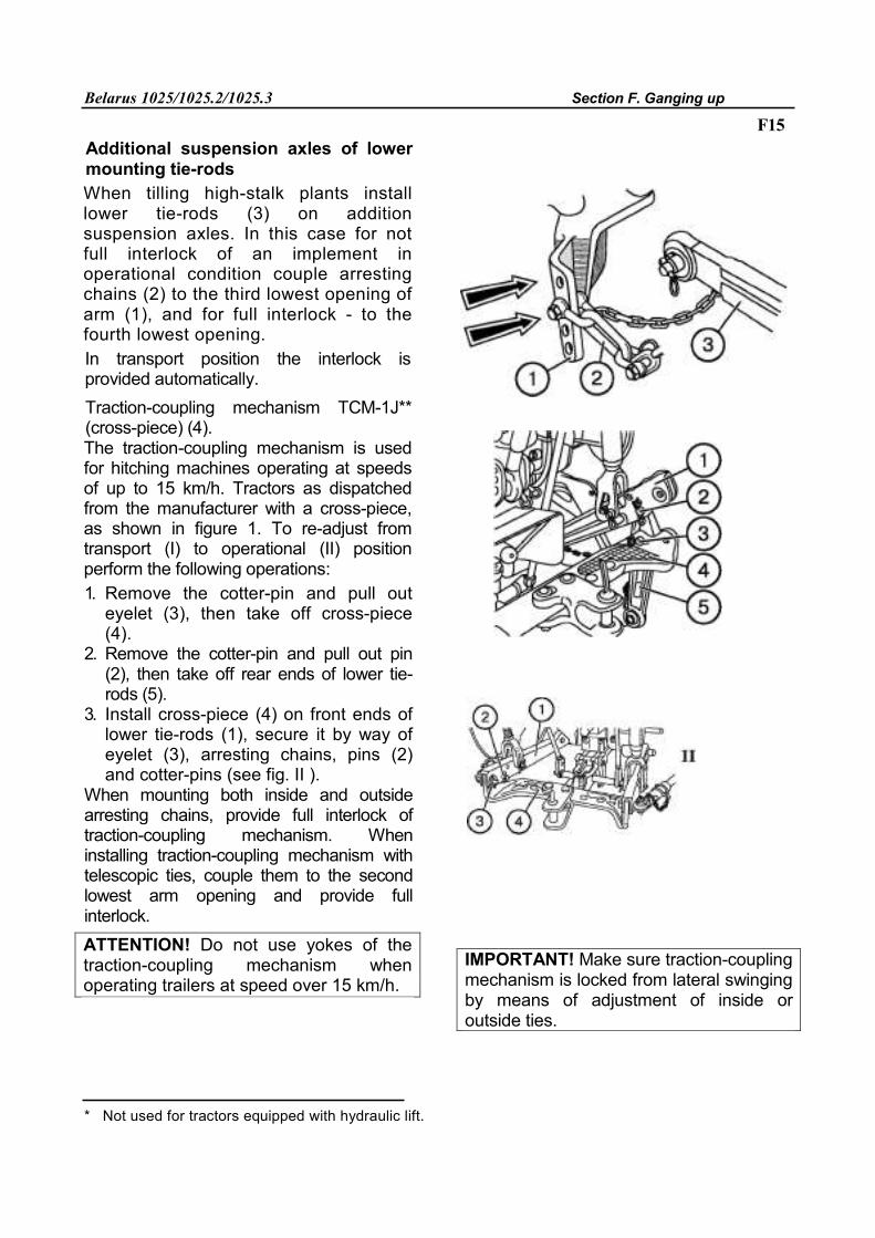
Belarus 1025/1025.2/1025.3 Section F. Ganging up
F15 Additional suspension axles of lower mounting tie-rods When tilling high-stalk plants install lower tie-rods (3) on addition suspension axles. In this case for not full interlock of an implement in operational condition couple arresting chains (2) to the third lowest opening of arm (1), and for full interlock - to the fourth lowest opening. In transport position the interlock is provided automatically. Traction-coupling mechanism TCM-1J** (cross-piece) (4). The traction-coupling mechanism is used for hitching machines operating at speeds of up to 15 km/h. Tractors as dispatched from the manufacturer with a cross-piece, as shown in figure 1. To re-adjust from transport (I) to operational (II) position perform the following operations: 1. Remove the cotter-pin and pull out
eyelet (3), then take off cross-piece (4).
2. Remove the cotter-pin and pull out pin (2), then take off rear ends of lower tie-rods (5).
3. Install cross-piece (4) on front ends of lower tie-rods (1), secure it by way of eyelet (3), arresting chains, pins (2) and cotter-pins (see fig. II ).
When mounting both inside and outside arresting chains, provide full interlock of traction-coupling mechanism. When installing traction-coupling mechanism with telescopic ties, couple them to the second lowest arm opening and provide full interlock. ATTENTION! Do not use yokes of the traction-coupling mechanism when operating trailers at speed over 15 km/h.
IMPORTANT! Make sure traction-coupling mechanism is locked from lateral swinging by means of adjustment of inside or outside ties.
* Not used for tractors equipped with hydraulic lift.
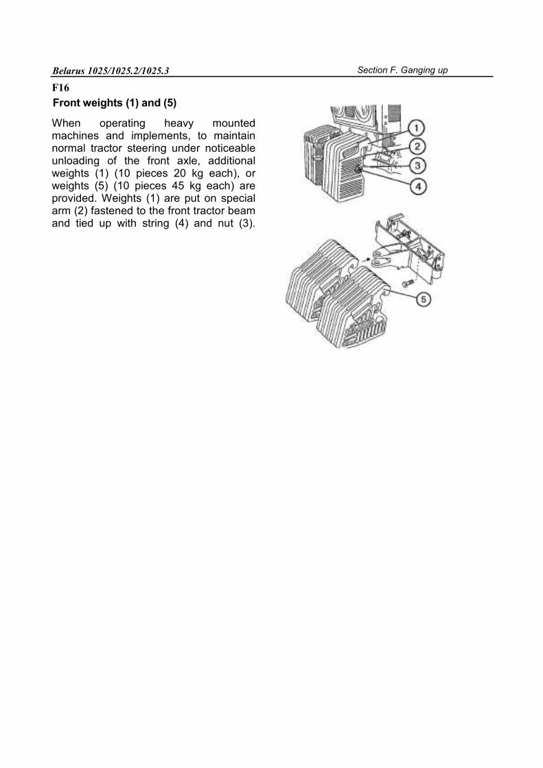
Belarus 1025/1025.2/1025.3 Section F. Ganging up
F16
Front weights (1) and (5)
When operating heavy mounted machines and implements, to maintain normal tractor steering under noticeable unloading of the front axle, additional weights (1) (10 pieces 20 kg each), or weights (5) (10 pieces 45 kg each) are provided. Weights (1) are put on special arm (2) fastened to the front tractor beam and tied up with string (4) and nut (3).
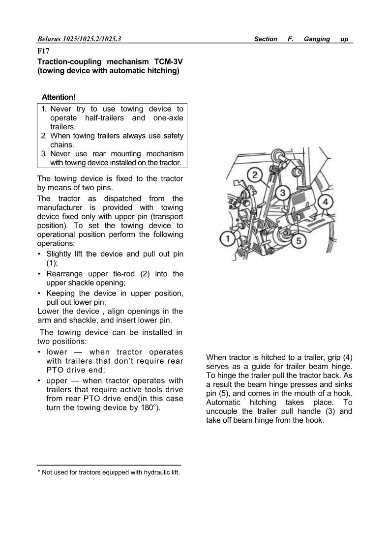
Belarus 1025/1025.2/1025.3 Section F. Ganging up
F17 Traction-coupling mechanism TCM-3V (towing device with automatic hitching)
Attention!1. Never try to use towing device to
operate half-trailers and one-axle trailers.
2. When towing trailers always use safety chains.
3. Never use rear mounting mechanism with towing device installed on the tractor.
The towing device is fixed to the tractor by means of two pins. The tractor as dispatched from the manufacturer is provided with towing device fixed only with upper pin (transport position). To set the towing device to operational position perform the following operations: • Slightly lift the device and pull out pin
(1); • Rearrange upper tie-rod (2) into the
upper shackle opening; • Keeping the device in upper position,
pull out lower pin; Lower the device , align openings in the arm and shackle, and insert lower pin. The towing device can be installed in two positions: • lower — when tractor operates
with trailers that don’t require rear PTO drive end;
• upper — when tractor operates with trailers that require active tools drive from rear PTO drive end(in this case turn the towing device by 180°).
When tractor is hitched to a trailer, grip (4) serves as a guide for trailer beam hinge. To hinge the trailer pull the tractor back. As a result the beam hinge presses and sinks pin (5), and comes in the mouth of a hook. Automatic hitching takes place. To uncouple the trailer pull handle (3) and take off beam hinge from the hook.
* Not used for tractors equipped with hydraulic lift.
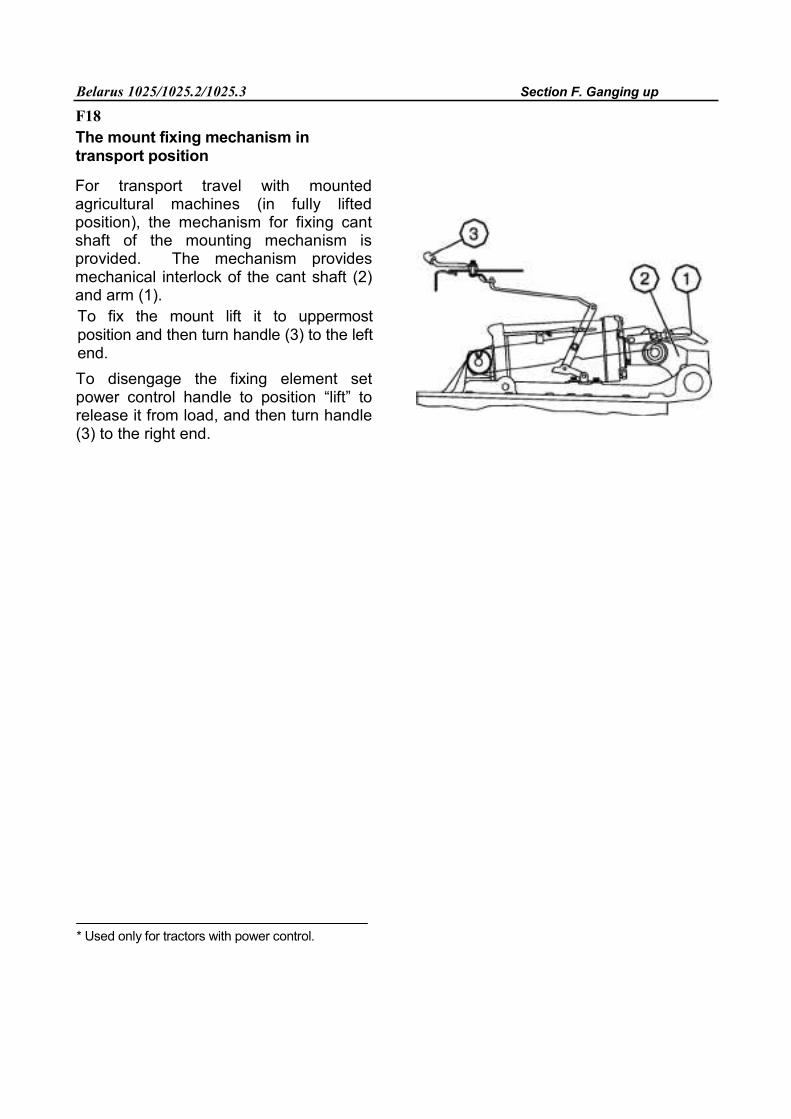
Belarus 1025/1025.2/1025.3 Section F. Ganging up
F18 The mount fixing mechanism in transport position
For transport travel with mounted agricultural machines (in fully lifted position), the mechanism for fixing cant shaft of the mounting mechanism is provided. The mechanism provides mechanical interlock of the cant shaft (2) and arm (1). To fix the mount lift it to uppermost position and then turn handle (3) to the left end. To disengage the fixing element set power control handle to position “lift” to release it from load, and then turn handle (3) to the right end.
* Used only for tractors with power control.
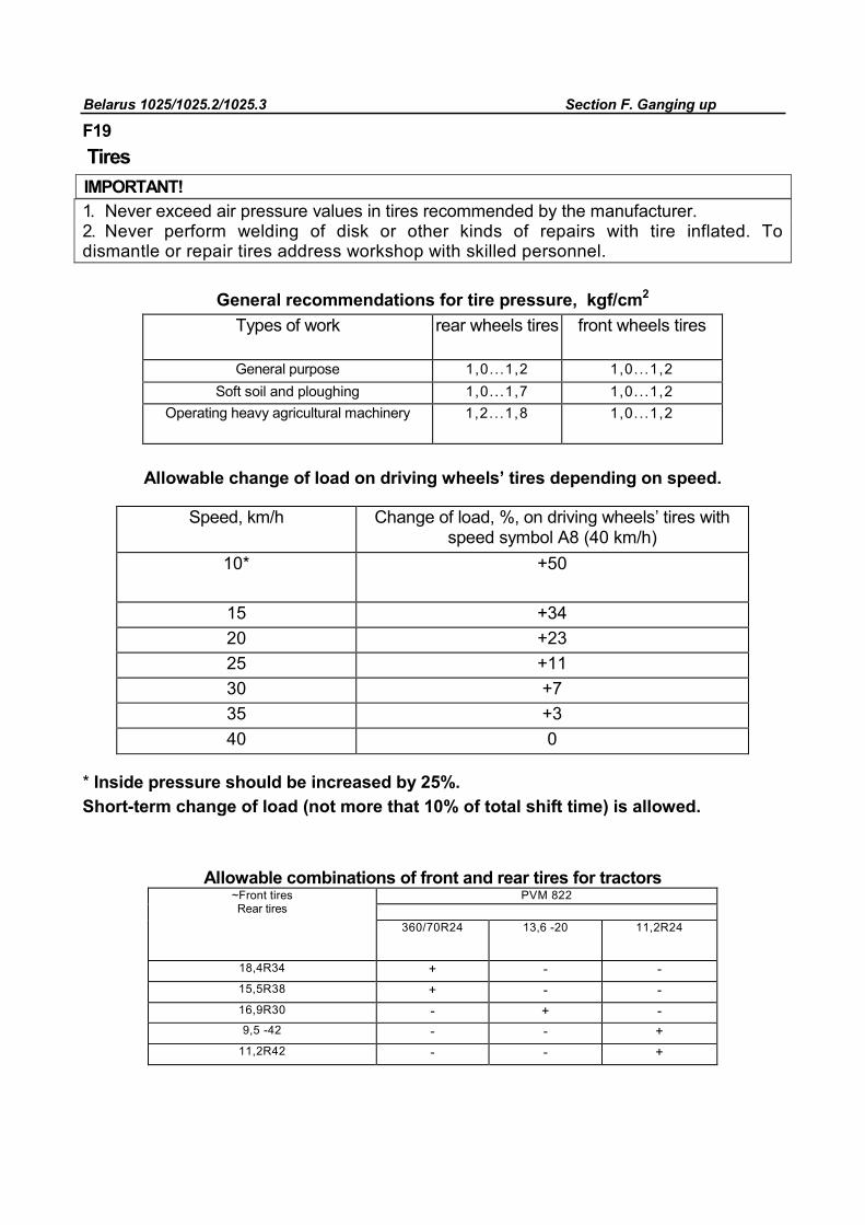
Belarus 1025/1025.2/1025.3 Section F. Ganging up
F19
Tires IMPORTANT! 1. Never exceed air pressure values in tires recommended by the manufacturer. 2. Never perform welding of disk or other kinds of repairs with tire inflated. To dismantle or repair tires address workshop with skilled personnel.
General recommendations for tire pressure, kgf/cm2
Types of work rear wheels tires front wheels tires
General purpose 1,0...1,2 1,0...1,2 Soft soil and ploughing 1,0...1,7 1,0...1,2
Operating heavy agricultural machinery 1,2...1,8 1,0...1,2
Allowable change of load on driving wheels’ tires depending on speed.
Speed, km/h Change of load, %, on driving wheels’ tires with speed symbol А8 (40 km/h)
10* +50
15 +34
20 +23
25 +11
30 +7
35 +3
40 0
* Inside pressure should be increased by 25%. Short-term change of load (not more that 10% of total shift time) is allowed.
Allowable combinations of front and rear tires for tractors
~Front tires Rear tires
PVM 822
360/70R24 13,6 -20 11,2R24
18,4R34 + - - 15,5R38 + - - 16,9R30 - + - 9,5 -42 - - +
11,2R42 - - +
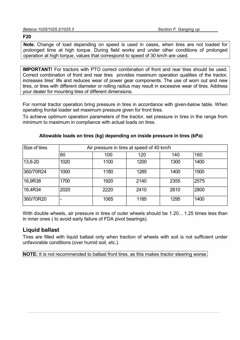
Belarus 1025/1025.2/1025.3 Section F. Ganging up
F20
Note. Change of load depending on speed is used in cases, when tires are not loaded for prolonged time at high torque. During field works and under other conditions of prolonged operation at high torque, values that correspond to speed of 30 km/h are used.
IMPORTANT! For tractors with PTO correct combination of front and rear tires should be used. Correct combination of front and rear tires provides maximum operation qualities of the tractor, increases tires’ life and reduces wear of power gear components. The use of worn out and new tires, or tires with different diameter or rolling radius may result in excessive wear of tires. Address your dealer for mounting tires of different dimensions.
For normal tractor operation bring pressure in tires in accordance with given-below table. When operating frontal loader set maximum pressure given for front tires. To achieve optimum operation parameters of the tractor, set pressure in tires in the range from minimum to maximum in compliance with actual loads on tires.
Allowable loads on tires (kg) depending on inside pressure in tires (kPa)
Size of tires Air pressure in tires at speed of 40 km/h
80 100 120 140 160
13,6-20 1020 1100 1200 1300 1400
360/70R24 1000 1180 1285 1400 1500
16,9R38 1700 1920 2140 2355 2575
18,4R34 2020 2220 2410 2610 2800
360/70R20 - 1065 1185 1295 1400
With double wheels, air pressure in tires of outer wheels should be 1.20... 1.25 times less than in inner ones ( to avoid early failure of FDA pivot bearings).
Liquid ballast
Tires are filled with liquid ballast only when traction of wheels with soil is not sufficient under unfavorable conditions (over humid soil, etc.).
NOTE: It is not recommended to ballast front tires, as this makes tractor steering worse.
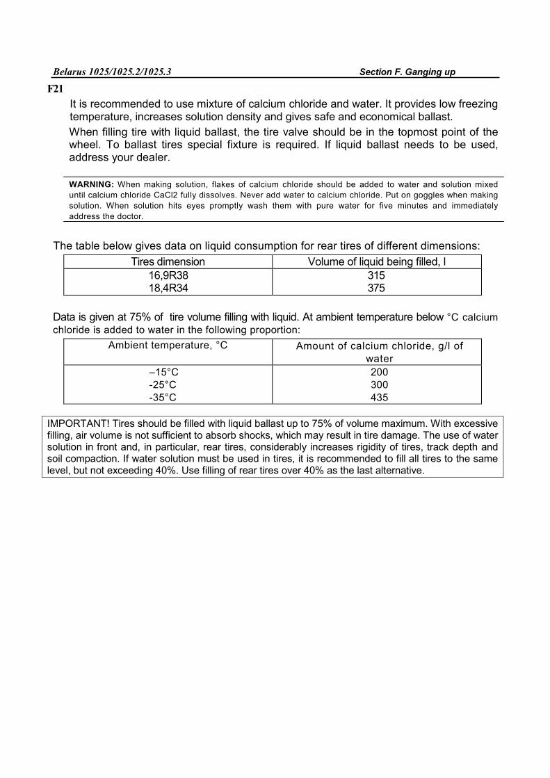
Belarus 1025/1025.2/1025.3 Section F. Ganging up
F21 It is recommended to use mixture of calcium chloride and water. It provides low freezing temperature, increases solution density and gives safe and economical ballast. When filling tire with liquid ballast, the tire valve should be in the topmost point of the wheel. To ballast tires special fixture is required. If liquid ballast needs to be used, address your dealer.
WARNING: When making solution, flakes of calcium chloride should be added to water and solution mixed until calcium chloride CaCl2 fully dissolves. Never add water to calcium chloride. Put on goggles when making solution. When solution hits eyes promptly wash them with pure water for five minutes and immediately address the doctor.
The table below gives data on liquid consumption for rear tires of different dimensions:
Tires dimension Volume of liquid being filled, l 16,9R38 18,4R34
315 375
Data is given at 75% of tire volume filling with liquid. At ambient temperature below °С calcium chloride is added to water in the following proportion:
Ambient temperature, °С Amount of calcium chloride, g/l of water
–15°С -25°С -35°С
200 300 435
IMPORTANT! Tires should be filled with liquid ballast up to 75% of volume maximum. With excessive filling, air volume is not sufficient to absorb shocks, which may result in tire damage. The use of water solution in front and, in particular, rear tires, considerably increases rigidity of tires, track depth and soil compaction. If water solution must be used in tires, it is recommended to fill all tires to the same level, but not exceeding 40%. Use filling of rear tires over 40% as the last alternative.
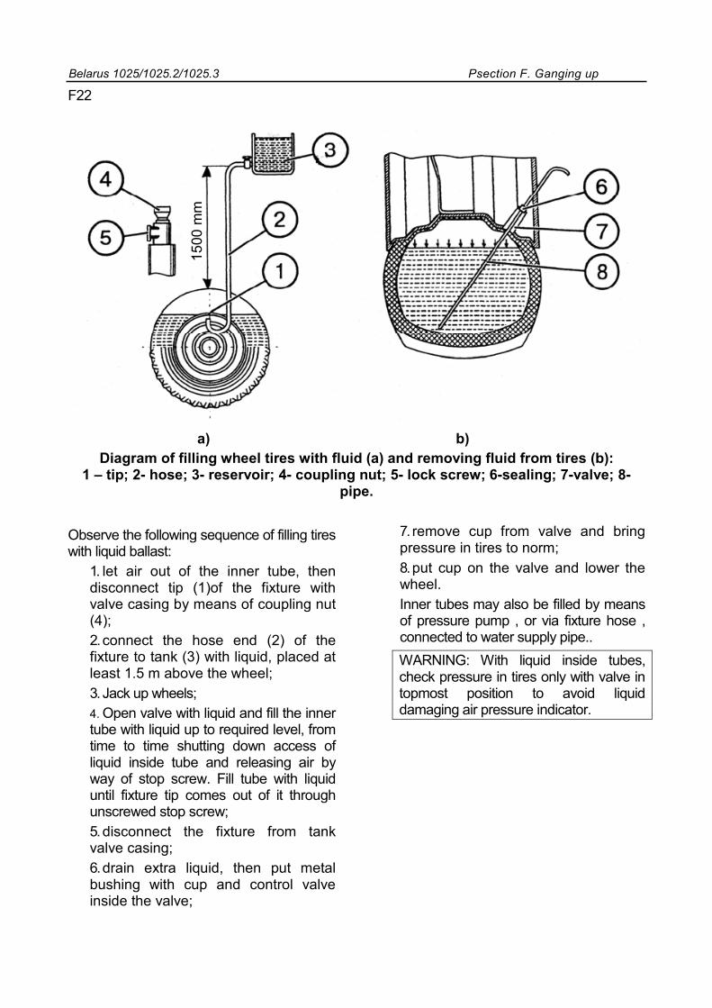
Belarus 1025/1025.2/1025.3 Рsection F. Ganging up
F22
a) b) Diagram of filling wheel tires with fluid (a) and removing fluid from tires (b):
1 – tip; 2- hose; 3- reservoir; 4- coupling nut; 5- lock screw; 6-sealing; 7-valve; 8- pipe.
Observe the following sequence of filling tires with liquid ballast:
1. let air out of the inner tube, then disconnect tip (1)of the fixture with valve casing by means of coupling nut (4); 2. connect the hose end (2) of the fixture to tank (3) with liquid, placed at least 1.5 m above the wheel; 3. Jack up wheels; 4. Open valve with liquid and fill the inner tube with liquid up to required level, from time to time shutting down access of liquid inside tube and releasing air by way of stop screw. Fill tube with liquid until fixture tip comes out of it through unscrewed stop screw; 5. disconnect the fixture from tank valve casing; 6. drain extra liquid, then put metal bushing with cup and control valve inside the valve;
7. remove cup from valve and bring pressure in tires to norm; 8. put cup on the valve and lower the wheel. Inner tubes may also be filled by means of pressure pump , or via fixture hose , connected to water supply pipe.. WARNING: With liquid inside tubes, check pressure in tires only with valve in topmost position to avoid liquid damaging air pressure indicator.
1500
mm
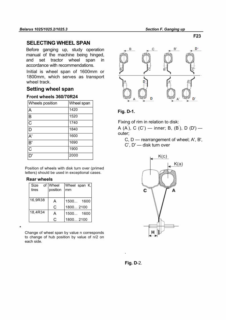
Belarus 1025/1025.2/1025.3 Section F. Ganging up
F23
SELECTING WHEEL SPAN
Before ganging up, study operation manual of the machine being hinged, and set tractor wheel span in accordance with recommendations. Initial is wheel span of 1600mm or 1800mm, which serves as transport wheel track. Setting wheel span Front wheels 360/70R24
Wheels position Wheel span
А 1420
В 1520
С 1740
D 1840
А' 1600
В' 1690
С 1900
D' 2000
Position of wheels with disk turn over (primed letters) should be used in exceptional cases.
Rear wheels
Size of tires
Wheel position
Wheel span К, mm
16,9R38 А С
1500... 1600 1800... 2100
18,4R34 А С
1500... 1600 1800... 2100
Change of wheel span by value n corresponds to change of hub position by value of n/2 on each side.
Fig. D-1.
Fixing of rim in relation to disk: А (А’), С (С’) — inner; В, (В’), D (D') — outer;
С, D — rearrangement of wheel; А', В', С’, D' — disk turn over .
Fig. D-2.
*
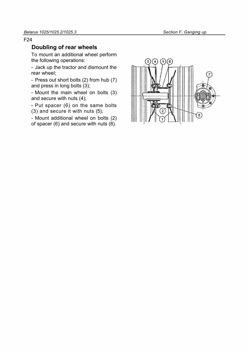
Belarus 1025/1025.2/1025.3 Section F. Ganging up
F24
Doubling of rear wheels
To mount an additional wheel perform the following operations: - Jack up the tractor and dismount the rear wheel; - Press out short bolts (2) from hub (7) and press in long bolts (3); - Mount the main wheel on bolts (3) and secure with nuts (4); - Put spacer (6) on the same bolts (3) and secure it with nuts (5); - Mount additional wheel on bolts (2) of spacer (6) and secure with nuts (8).
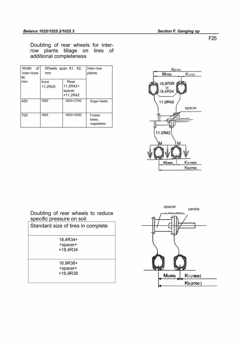
Belarus 1025/1025.2/1025.3 Section F. Ganging up
F25 Doubling of rear wheels for inter-row plants tillage on tires of additional completeness
Width of inter-rows М, mm
Wheels span К1, К2, mm
Inter-row plants
front 11,2R20
Rear 11,2R42+ spacer +11,2R42
450 1800 1800+2700 Sugar beets
700 1800 1800+3000 Fodder beets, vegetables
Doubling of rear wheels to reduce specific pressure on soil Standard size of tires in complete
18,4R34+ +spacer+ +18,4R34
16,9R38+ +spacer+ +16,9R38
spacer centre
Belarus 1025/1025.2/1025.3 Section F. Ganging up
F26 Conditions of safe ganging up To ensure safe and reliable tractor operation follow recommendations providing for stability, allowable loads on axles and tires at different movement speed and air pressure in them. Load on the front axle should always (with hinged implement or without it) be at least 20% (0.2) of operation tractor mass itself. Otherwise the tractor will not be stable enough in steering. ATTENTION! 1. Load on tires, as well as type and
mass of ballast can be determined only by weighting. When purpose of use changes, always correct ballast mass and air pressure in tires. 2. Values of limit and intermediate
loads on tractor tires, as well as values of relative inside pressure, are set by the manufacturer of tires and given in the table.
3. To determine value of load on tires use the following method of tractor weighting: - Front axle is weighted (with machines lowered down); - Rear axle is weighted (with lifted machines); - The concrete value of mass part on the wheel is estimated by dividing by half (by two), of the weighted value, correspondingly, front or rear axle.
ATTENTION! During operations with large torque (ploughing, etc.) observe recommendations valid for 30 km/h. Total load-carrying capacity of double tires should not exceed single tire load-carrying capacity by not more than 1.7 times. 4. Adding weight to tires by filling tractor tires with solution should be used only in case of insufficient wheels traction with soil under unfavorable conditions (over humid soil, etc.). If wheels traction is satisfactory, tires filling is not recommended due to overloading of transmission and operation tractor mounting equipment. Under no circumstances fill tires to the full, as their carcass may break when running over an obstacle.
Maximum allowable load on tractor axle*, kN*, Maximum allowable operation tractor mass, kN (kg)
front rear
70 (7140) BELARUS 1025 24 53 BELARUS 1025.2 38 53 BELARUS 1025.3 38 53
* If by results of weighting and additional ballasting load values exceed allowable, ganging up of such machines is forbidden.
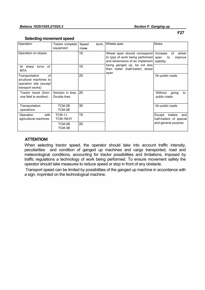
Belarus 1025/1025.2/1025.3 Section F. Ganging up
F27
Selecting movement speed
Operation Tractor complete equipment
Speed km/h, maxе
Wheels span Notes
Operation on slopes 10 Wheel span should correspond to type of work being performed and dimensions of an implement being ganged up: be not less than trailer (half-trailer) wheel span
Increase of wheel span to improve stability
At sharp turns of MTA
10
Transportation of a/cultural machines to operation site (except transport works)
20 On public roads
Tractor travel (from one field to another)
Solution in tires. Double tires
20 Without going to public roads
Transportation operations
TCM-2В TCM-3В
30 On public roads
Operation with agricultural machines
TCM-1J TCM-1М-01
15 Except trailers and half-trailers of special and general purpose TCM-2В
TCM-3В 20
ATTENTION! When selecting tractor speed, the operator should take into account traffic intensity, peculiarities and condition of ganged up machines and cargo transported, road and meteorological conditions, accounting for tractor possibilities and limitations, imposed by traffic regulations a technology of work being performed. To ensure movement safety the operator should take measures to reduce speed or stop in front of any obstacle. Transport speed can be limited by possibilities of the ganged up machine in accordance with a sign, imprinted on the technological machine.
Belarus 1025/1025.2/1025.3 Section F. Ganging up
F28
Movement of tractor on public roads More stringent requirements are imposed an vehicles travelling on public roads. During movement the tractor and ganged up machine should comply with directions for technical operation. The tractor owner and operator are responsible for observance of official requirements of traffic regulations and technical requirements of non-rail vehicles operation. Machines with width exceeding tractor dimensions should be equipped with cat eyes. Movement on public roads of tractors overall dimensions of which, be it with a machine or without machine, with trailers or half-trailers, loaded or unloaded, requires special permits and according to special rules, if at least one of the following indices is exceeded: 1. by height - 4 m from the road surface. 2. By width - 2.55 m. 3. By length - 20 m for tractors as part of long vehicle (road train). 4. if cargo extends beyond transport vehicle dimensions by two meters and above. Deviation from given norms requires agreement of authorities responsible for traffic regulation.
It is forbidden to: • To gang up machines and transport cargo, when load distribution on axles and tires exceeds values given in tractor operation manual. • use trailed and half-trailed machines , including trailers and half-trailers, without safety steel ropes (chains). Safety chain (steel rope) should be fixed on the tractor in one of vacant openings of the mounting mechanism (attach hardware should be included in the complete equipment of the machine being ganged up). • Use machines on the basis of trailers and half-trailers (of general and special purpose) not equipped with wheel and parking brakes. • Use TCM-1J (cross-piece) for transportation of general purpose motor-vehicles, except works performance in assembly with agricultural machines. • Move on all roads, including railway crossings, with machines not set to transport position •Move without special permit across railway crossings of electrical railroad sections when dimensions by height exceed four meters. • Move on public roads in the reverse mode, as light and illumination devices are designed for forward movement only.
• Tow agricultural machines loaded with technological cargo. • Trailer-based machines should have plates with maximum speed limit signs attached on the front or left-hand side. It is desirable to have tractor wheel span matched to trailer (half-trailer) wheel span during transport works.
Belarus 1025/1025.2/1025.3 Section F. Ganging up
• Ganging up of the tractor as part of road train (tractor + half-trailer + trailer) is allowed only on roads with hard and dry surface and slope not more than 4%. • Seven-pin socket is provided on the tractor for connecting alarm devices of machines being ganged up. • Do not allow people in trailers of agricultural machines during movement and mounted mechanism operation.
F29
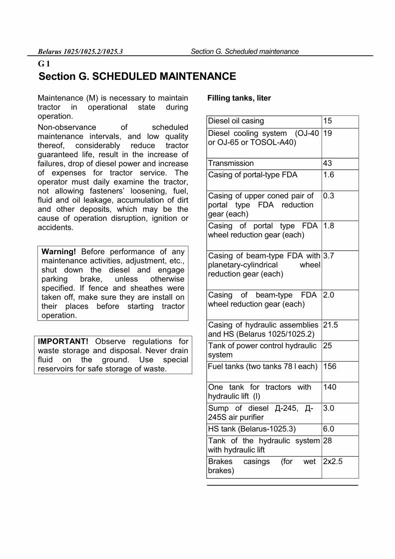
Belarus 1025/1025.2/1025.3 Section G. Scheduled maintenance
G 1
Section G. SCHEDULED MAINTENANCE
Maintenance (M) is necessary to maintain tractor in operational state during operation. Non-observance of scheduled maintenance intervals, and low quality thereof, considerably reduce tractor guaranteed life, result in the increase of failures, drop of diesel power and increase of expenses for tractor service. The operator must daily examine the tractor, not allowing fasteners’ loosening, fuel, fluid and oil leakage, accumulation of dirt and other deposits, which may be the cause of operation disruption, ignition or accidents.
Warning! Before performance of any maintenance activities, adjustment, etc., shut down the diesel and engage parking brake, unless otherwise specified. If fence and sheathes were taken off, make sure they are install on their places before starting tractor operation.
IMPORTANT! Observe regulations for waste storage and disposal. Never drain fluid on the ground. Use special reservoirs for safe storage of waste.
Filling tanks, liter
Diesel oil casing 15
Diesel cooling system (OJ-40 or OJ-65 or TOSOL-А40)
19
Transmission 43
Casing of portal-type FDA 1.6
Casing of upper coned pair of portal type FDA reduction gear (each)
0.3
Casing of portal type FDA wheel reduction gear (each)
1.8
Casing of beam-type FDA with planetary-cylindrical wheel reduction gear (each)
3.7
Casing of beam-type FDA wheel reduction gear (each)
2.0
Casing of hydraulic assemblies and HS (Belarus 1025/1025.2)
21.5
Tank of power control hydraulic system
25
Fuel tanks (two tanks 78 l each) 156
One tank for tractors with hydraulic lift (l)
140
Sump of diesel Д-245, Д-245S air purifier
3.0
HS tank (Belarus-1025.3) 6.0
Tank of the hydraulic system with hydraulic lift
28
Brakes casings (for wet brakes)
2x2.5
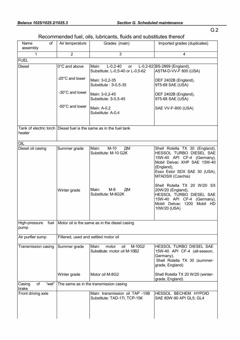
Belarus 1025/1025.2/1025.3 Section G. Scheduled maintenance
G 2 Recommended fuel, oils, lubricants, fluids and substitutes thereof
Name of assembly
Air temperature Grades (main) Imported grades (duplicates)
1 2 3 4 FUEL Diesel 0°С and above
-20°С and lower
-30°С and lower
-50°С and lower
Main: L-0,2-40 or L-0,2-62 Substitute: L-0,5-40 or L-0,5-62 Main: 3-0,2-35 Substitute : З-0,5-35 Main: 3-0,2-45 Substitute: З-0,5-45 Main: A-0,2 Substitute: A-0,4
BS-2869 (England), ASTM-D-VV-F 800 (USA) DEF 2402B (England), 975-68 SAE (USA) DEF 2402B (England), 975-68 SAE (USA) SAE VV-F-800 (USA)
Tank of electric torch heater
Diesel fuel is the same as in the fuel tank
OIL Diesel oil casing Summer grade
Winter grade
Main: M-10 ДМ Substitute: М-10 G2К Main: М-8 ДМ Substitute: М-8G2К
Shell Rotella TX 30 (England), HESSOL TURBO DIESEL SAE 15W-40 API CF-4 (Germany), Mobil Delvac XHP SAE 15W-40 (England), Esso Estor SDX SAE 30 (USA), M7ADSIII (Czechia) Shell Rotella TX 20 W/20 SX 20W/20 (England), HESSOL TURBO DIESEL SAE 15W-40 API CF-4 (Germany), Mobil Delvac 1200 Mobil HD 10W/20 (USA)
High-pressure fuel pump
Motor oil is the same as in the diesel casing
Air purifier sump Filtered, used and settled motor oil
Transmission casing Summer grade Winter grade
Main: motor oil М-10G2 Substitute: motor oil М-10В2 Motor oil М-8G2
HESSOL TURBO DIESEL SAE 15W-40 API CF-4 (all-season, Germany), Shell Rotella TX 30 (summer-grade, England) Shell Rotella TX 20 W/20 (winter-grade, England)
Casing of “wet” brake
The same as in the transmission casing
Front driving axle Main: transmission oil ТАP -15В Substitute: ТАD-17I, ТСP-15К
HESSOL BECHEM HYPOID SAE 80W-90 API GL5; GL4
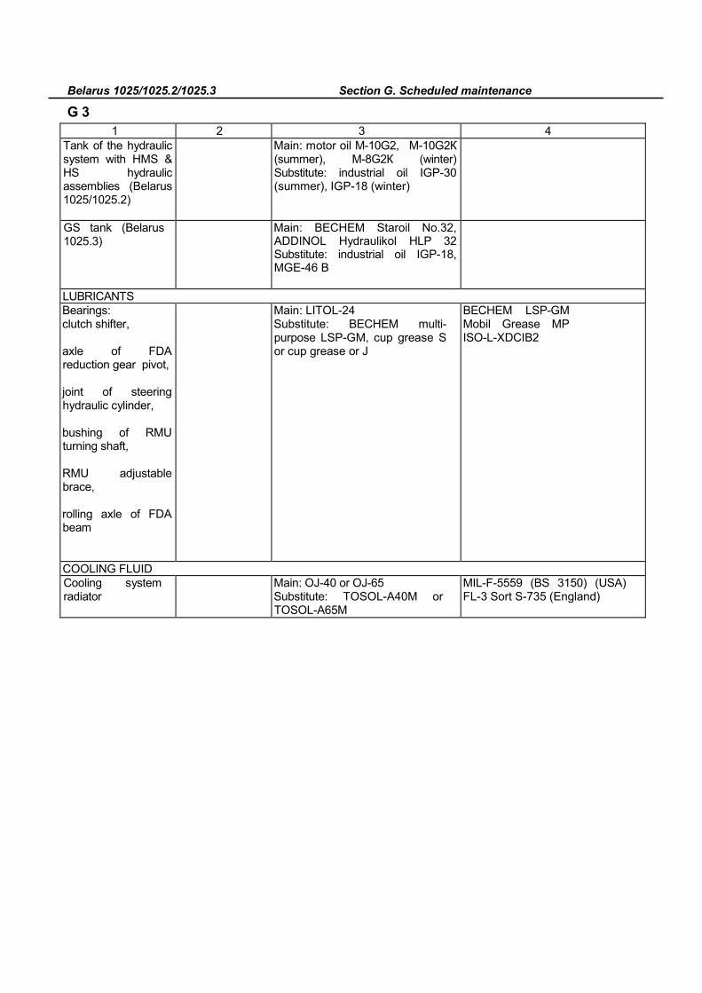
Belarus 1025/1025.2/1025.3 Section G. Scheduled maintenance
G 3
1 2 3 4 Tank of the hydraulic system with HMS & HS hydraulic assemblies (Belarus 1025/1025.2)
Main: motor oil М-10G2, М-10G2К (summer), М-8G2К (winter) Substitute: industrial oil IGP-30 (summer), IGP-18 (winter)
GS tank (Belarus 1025.3)
Main: BECHEM Staroil No.32, ADDINOL Hydraulikol HLP 32 Substitute: industrial oil IGP-18, МGЕ-46 В
LUBRICANTS Bearings: clutch shifter, axle of FDA reduction gear pivot, joint of steering hydraulic cylinder, bushing of RMU turning shaft, RMU adjustable brace, rolling axle of FDA beam
Main: LITOL-24 Substitute: BECHEM multi-purpose LSP-GM, cup grease S or cup grease or J
ВЕСНЕМ LSP-GM Mobil Grease MP ISO-L-XDCIB2
COOLING FLUID Cooling system radiator
Main: ОJ-40 or ОJ-65 Substitute: TOSOL-А40М or TOSOL-А65М
MIL-F-5559 (BS 3150) (USA) FL-3 Sort S-735 (England)
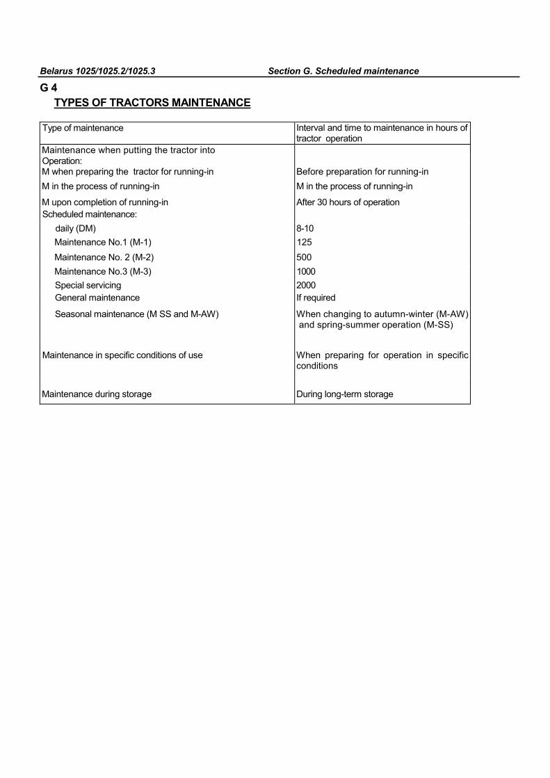
Belarus 1025/1025.2/1025.3 Section G. Scheduled maintenance
G 4 TYPES OF TRACTORS MAINTENANCE
Type of maintenance Interval and time to maintenance in hours of tractor operation
Maintenance when putting the tractor into
Operation: M when preparing the tractor for running-in Before preparation for running-in M in the process of running-in M in the process of running-in
M upon completion of running-in After 30 hours of operation Scheduled maintenance:
daily (DM) 8-10 Maintenance No.1 (M-1) 125 Maintenance No. 2 (M-2) 500 Maintenance No.3 (M-3) 1000 Special servicing 2000 General maintenance If required
Seasonal maintenance (M SS and M-AW) When changing to autumn-winter (M-AW) and spring-summer operation (M-SS)
Maintenance in specific conditions of use When preparing for operation in specific
conditions
Maintenance during storage During long-term storage
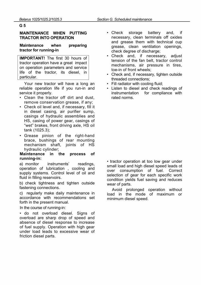
Belarus 1025/1025.2/1025.3 Section G. Scheduled maintenance
G 5
MAINTENANCE WHEN PUTTING TRACTOR INTO OPERATION
Maintenance when preparing tractor for running-in
IMPORTANT! The first 30 hours of tractor operation have a great impact on operation parameters and service life of the tractor, its diesel, in particular.
Your new tractor will have a long an reliable operation life if you run-in and service it properly. • Clean the tractor off dirt and dust,
remove conservation grease, if any; • Check oil level and, if necessary, fill it
in diesel casing, air purifier sump, casings of hydraulic assemblies and HS, casing of power gear, casings of “wet” brakes, front driving axle, HS oil tank (1025.3);
• Grease pinion of the right-hand brace, bushings of rear mounting mechanism shaft, joints of HS hydraulic cylinder;
Maintenance in the process of running-in: а) monitor instruments’ readings, operation of lubrication , cooling and supply systems. Control level of oil and fluid in filling reservoirs. b) check tightness and tighten outside fastening connections. c) regularly make daily maintenance in accordance with recommendations set forth in the present manual. In the course of running-in: • do not overload diesel. Signs of overload are sharp drop of speed and absence of diesel response to increase of fuel supply. Operation with high gear under load leads to excessive wear of friction diesel parts.
• Check storage battery and, if necessary, clean terminals off oxides and grease them with technical cup grease, clean ventilation openings, check degree of discharge;
• Check and, if necessary, adjust tension of the fan belt, tractor control mechanisms, air pressure in tires, toe-in of front wheels;
• Check and, if necessary, tighten outside threaded connections;
• Fill radiator with cooling fluid; • Listen to diesel and check readings of
instrumentation for compliance with rated norms.
• tractor operation at too low gear under small load and high diesel speed leads ot over consumption of fuel. Correct selection of gear for each specific work condition yields fuel saving and reduces wear of parts.
Avoid prolonged operation without load in the mode of maximum or minimum diesel speed.
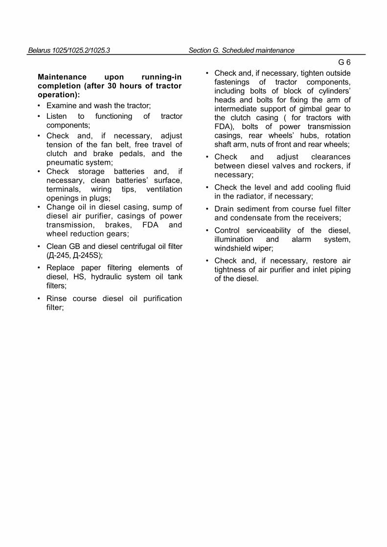
Belarus 1025/1025.2/1025.3 Section G. Scheduled maintenance
Maintenance upon running-in completion (after 30 hours of tractor operation): • Examine and wash the tractor; • Listen to functioning of tractor
components; • Check and, if necessary, adjust
tension of the fan belt, free travel of clutch and brake pedals, and the pneumatic system;
• Check storage batteries and, if necessary, clean batteries’ surface, terminals, wiring tips, ventilation openings in plugs;
• Change oil in diesel casing, sump of diesel air purifier, casings of power transmission, brakes, FDA and wheel reduction gears;
• Clean GB and diesel centrifugal oil filter (Д-245, Д-245S);
• Replace paper filtering elements of diesel, HS, hydraulic system oil tank filters;
• Rinse course diesel oil purification filter;
G 6
• Check and, if necessary, tighten outside fastenings of tractor components, including bolts of block of cylinders’ heads and bolts for fixing the arm of intermediate support of gimbal gear to the clutch casing ( for tractors with FDA), bolts of power transmission casings, rear wheels’ hubs, rotation shaft arm, nuts of front and rear wheels;
• Check and adjust clearances between diesel valves and rockers, if necessary;
• Check the level and add cooling fluid in the radiator, if necessary;
• Drain sediment from course fuel filter and condensate from the receivers;
• Control serviceability of the diesel, illumination and alarm system, windshield wiper;
• Check and, if necessary, restore air tightness of air purifier and inlet piping of the diesel.
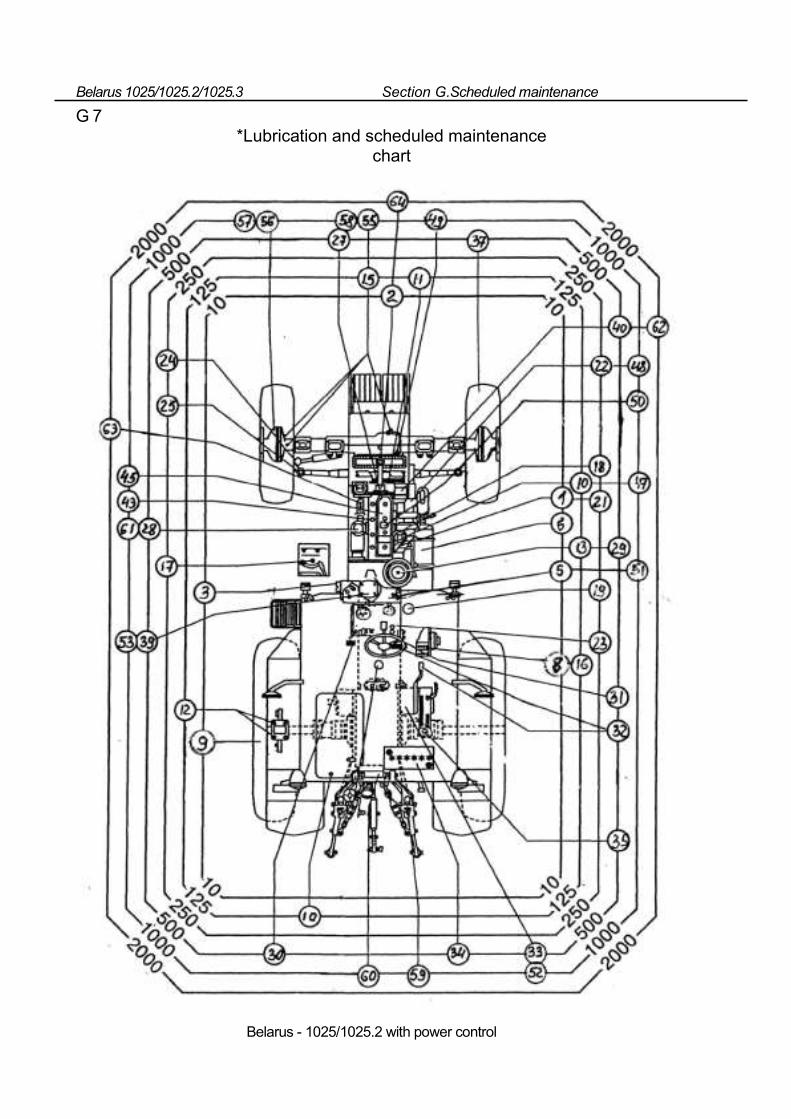
Belarus 1025/1025.2/1025.3 Section G.Scheduled maintenance
G 7 *Lubrication and scheduled maintenance
chart
Belarus - 1025/1025.2 with power control
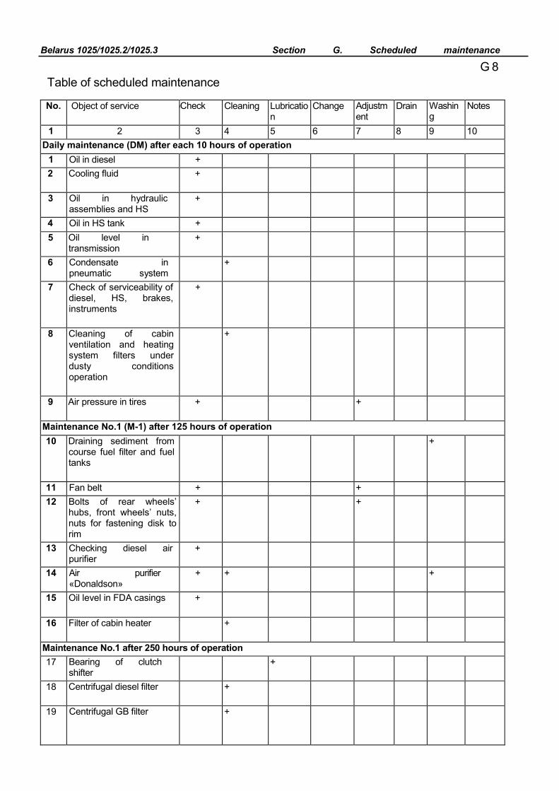
Belarus 1025/1025.2/1025.3 Section G. Scheduled maintenance
G 8 Table of scheduled maintenance
No. Object of service рCheck Cleaning Lubrication
Change Adjustment
Drain Washing
Notes
1 2 3 4 5 6 7 8 9 10 Daily maintenance (DM) after each 10 hours of operation
1 Oil in diesel + 2 Cooling fluid +
3 Oil in hydraulic assemblies and HS
+
4 Oil in HS tank + 5 Oil level in
transmission +
6 Condensate in pneumatic system
li d
+
7 Check of serviceability of diesel, HS, brakes, instruments
+
8 Cleaning of cabin ventilation and heating system filters under dusty conditions operation
+
9 Air pressure in tires + +
Maintenance No.1 (M-1) after 125 hours of operation 10 Draining sediment from
course fuel filter and fuel tanks
+
11 Fan belt + + 12 Bolts of rear wheels’
hubs, front wheels’ nuts, nuts for fastening disk to rim
+ +
13 Checking diesel air purifier
+
14 Air purifier «Donaldson»
+ + +
15 Oil level in FDA casings +
16 Filter of cabin heater +
Maintenance No.1 after 250 hours of operation 17 Bearing of clutch
shifter +
18 Centrifugal diesel filter +
19 Centrifugal GB filter +
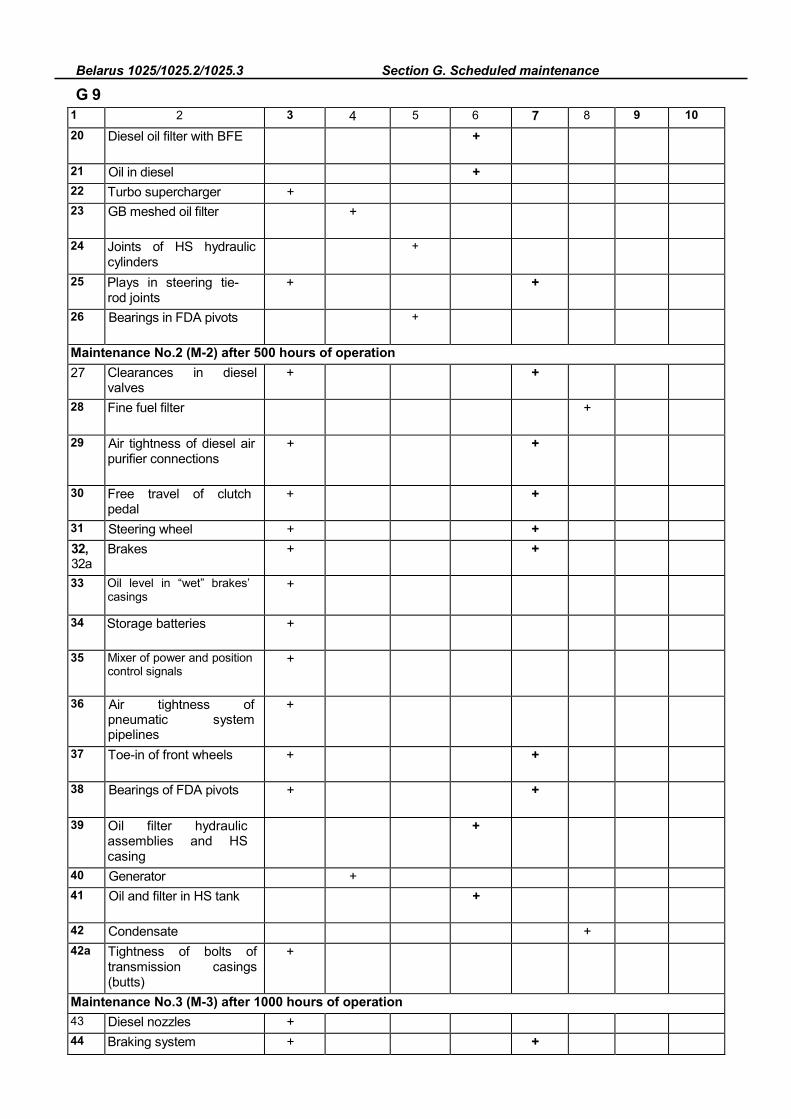
Belarus 1025/1025.2/1025.3 Section G. Scheduled maintenance
G 9
1 2 3 4 5 6 7 8 9 10 20 Diesel oil filter with BFE +
21 Oil in diesel + 22 Turbo supercharger + 23 GB meshed oil filter +
24 Joints of HS hydraulic cylinders
+
25 Plays in steering tie-rod joints
+ +
26 Bearings in FDA pivots +
Maintenance No.2 (M-2) after 500 hours of operation 27 Clearances in diesel
valves + +
28 Fine fuel filter +
29 Air tightness of diesel air purifier connections
+ +
30 Free travel of clutch pedal
+ +
31 Steering wheel + + 32, 32а
Brakes + +
33 Oil level in “wet” brakes’ casings
+
34 Storage batteries +
35 Mixer of power and position control signals
+
36 Air tightness of pneumatic system pipelines
+
37 Toe-in of front wheels + +
38 Bearings of FDA pivots + +
39 Oil filter hydraulic assemblies and HS casing
+
40 Generator + 41 Oil and filter in HS tank +
42 Condensate + 42а Tightness of bolts of
transmission casings (butts)
+
Maintenance No.3 (M-3) after 1000 hours of operation 43 Diesel nozzles + 44 Braking system + +
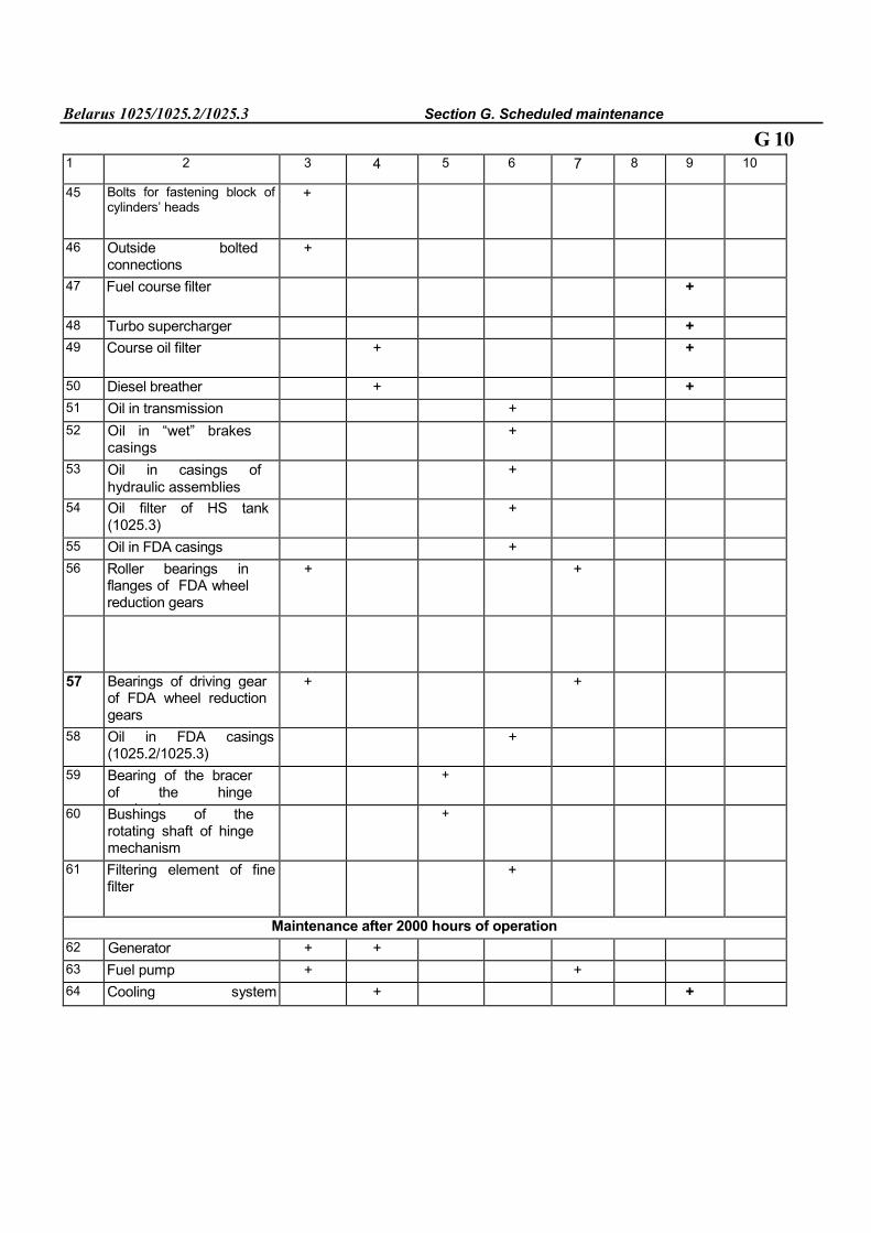
Belarus 1025/1025.2/1025.3 Section G. Scheduled maintenance
G 10
1 2 3 4 5 6 7 8 9 10
45 Bolts for fastening block of cylinders’ heads
+
46 Outside bolted connections
+
47 Fuel course filter +
48 Turbo supercharger + 49 Course oil filter + +
50 Diesel breather + + 51 Oil in transmission + 52 Oil in “wet” brakes
casings +
53 Oil in casings of hydraulic assemblies
+
54 Oil filter of HS tank (1025.3)
+
55 Oil in FDA casings + 56 Roller bearings in
flanges of FDA wheel reduction gears
+ +
57 Bearings of driving gear of FDA wheel reduction gears
+ +
58 Oil in FDA casings (1025.2/1025.3)
+
59 Bearing of the bracer of the hinge
h i
+
60 Bushings of the rotating shaft of hinge mechanism
+
61 Filtering element of fine filter
+
Maintenance after 2000 hours of operation 62 Generator + + 63 Fuel pump + + 64 Cooling system
+ +
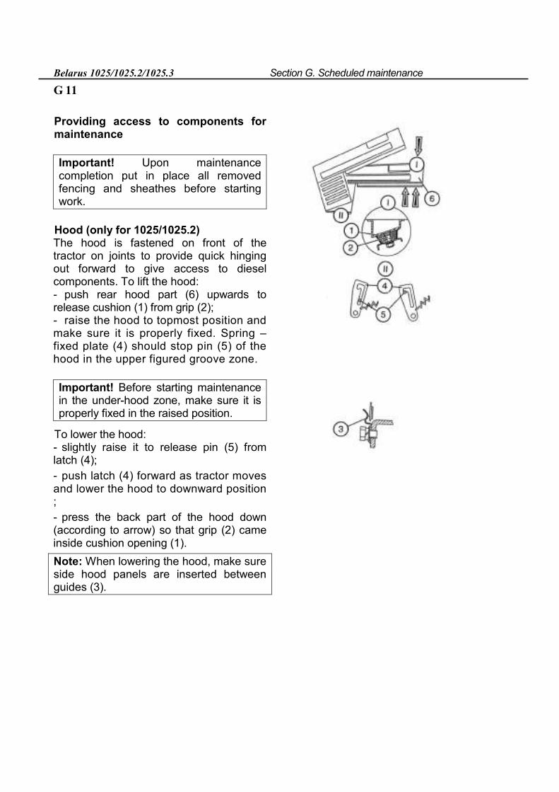
Belarus 1025/1025.2/1025.3 Section G. Scheduled maintenance
G 11
Providing access to components for maintenance
Important! Upon maintenance completion put in place all removed fencing and sheathes before starting work.
Hood (only for 1025/1025.2) The hood is fastened on front of the tractor on joints to provide quick hinging out forward to give access to diesel components. To lift the hood: - push rear hood part (6) upwards to release cushion (1) from grip (2); - raise the hood to topmost position and make sure it is properly fixed. Spring –fixed plate (4) should stop pin (5) of the hood in the upper figured groove zone.
Important! Before starting maintenance in the under-hood zone, make sure it is properly fixed in the raised position.
To lower the hood: - slightly raise it to release pin (5) from latch (4); - push latch (4) forward as tractor moves and lower the hood to downward position ; - press the back part of the hood down (according to arrow) so that grip (2) came inside cushion opening (1). Note: When lowering the hood, make sure side hood panels are inserted between guides (3).
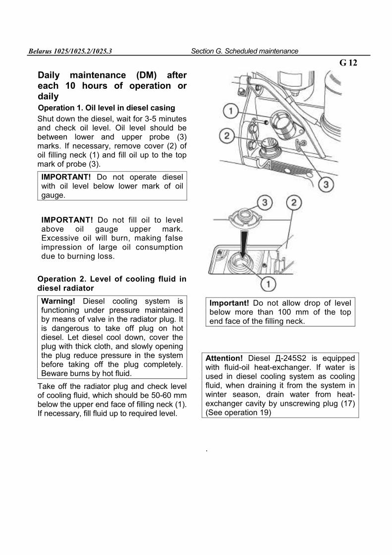
Belarus 1025/1025.2/1025.3 Section G. Scheduled maintenance
G 12
Daily maintenance (DM) after each 10 hours of operation or daily
Operation 1. Oil level in diesel casing
Shut down the diesel, wait for 3-5 minutes and check oil level. Oil level should be between lower and upper probe (3) marks. If necessary, remove cover (2) of oil filling neck (1) and fill oil up to the top mark of probe (3). IMPORTANT! Do not operate diesel with oil level below lower mark of oil gauge.
IMPORTANT! Do not fill oil to level above oil gauge upper mark. Excessive oil will burn, making false impression of large oil consumption due to burning loss.
Operation 2. Level of cooling fluid in diesel radiator
Warning! Diesel cooling system is functioning under pressure maintained by means of valve in the radiator plug. It is dangerous to take off plug on hot diesel. Let diesel cool down, cover the plug with thick cloth, and slowly opening the plug reduce pressure in the system before taking off the plug completely. Beware burns by hot fluid.
Take off the radiator plug and check level of cooling fluid, which should be 50-60 mm below the upper end face of filling neck (1). If necessary, fill fluid up to required level.
Important! Do not allow drop of level below more than 100 mm of the top end face of the filling neck.
Attention! Diesel Д-245S2 is equipped with fluid-oil heat-exchanger. If water is used in diesel cooling system as cooling fluid, when draining it from the system in winter season, drain water from heat-exchanger cavity by unscrewing plug (17) (See operation 19)
.
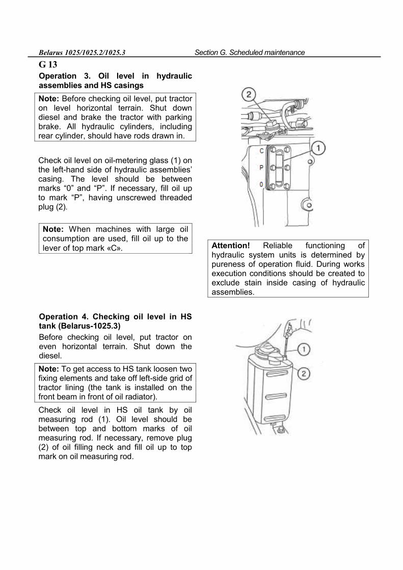
Belarus 1025/1025.2/1025.3 Section G. Scheduled maintenance
G 13 Operation 3. Oil level in hydraulic assemblies and HS casings
Note: Before checking oil level, put tractor on level horizontal terrain. Shut down diesel and brake the tractor with parking brake. All hydraulic cylinders, including rear cylinder, should have rods drawn in.
Check oil level on oil-metering glass (1) on the left-hand side of hydraulic assemblies’ casing. The level should be between marks “0” and “P”. If necessary, fill oil up to mark “P”, having unscrewed threaded plug (2).
Note: When machines with large oil consumption are used, fill oil up to the lever of top mark «С». Attention! Reliable functioning of
hydraulic system units is determined by pureness of operation fluid. During works execution conditions should be created to exclude stain inside casing of hydraulic assemblies.
Operation 4. Checking oil level in HS tank (Belarus-1025.3) Before checking oil level, put tractor on even horizontal terrain. Shut down the diesel. Note: To get access to HS tank loosen two fixing elements and take off left-side grid of tractor lining (the tank is installed on the front beam in front of oil radiator). Check oil level in HS oil tank by oil measuring rod (1). Oil level should be between top and bottom marks of oil measuring rod. If necessary, remove plug (2) of oil filling neck and fill oil up to top mark on oil measuring rod.
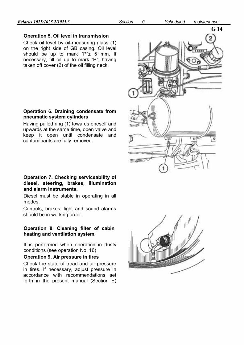
Belarus 1025/1025.2/1025.3 Section G. Scheduled maintenance
G 14 Operation 5. Oil level in transmission Check oil level by oil-measuring glass (1) on the right side of GB casing. Oil level should be up to mark “P”± 5 mm. If necessary, fill oil up to mark “P”, having taken off cover (2) of the oil filling neck.
Operation 6. Draining condensate from pneumatic system cylinders
Having pulled ring (1) towards oneself and upwards at the same time, open valve and keep it open until condensate and contaminants are fully removed. Operation 7. Checking serviceability of diesel, steering, brakes, illumination and alarm instruments. Diesel must be stable in operating in all modes. Controls, brakes, light and sound alarms should be in working order.
Operation 8. Cleaning filter of cabin heating and ventilation system.
It is performed when operation in dusty conditions (see operation No. 16) Operation 9. Air pressure in tires Check the state of tread and air pressure in tires. If necessary, adjust pressure in accordance with recommendations set forth in the present manual (Section E)
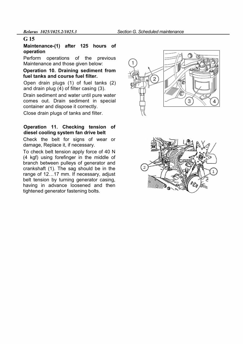
Belarus 1025/1025.2/1025.3 Section G. Scheduled maintenance
G 15
Maintenance-(1) after 125 hours of operation Perform operations of the previous Maintenance and those given below: Operation 10. Draining sediment from fuel tanks and course fuel filter. Open drain plugs (1) of fuel tanks (2) and drain plug (4) of filter casing (3). Drain sediment and water until pure water comes out. Drain sediment in special container and dispose it correctly. Close drain plugs of tanks and filter.
Operation 11. Checking tension of diesel cooling system fan drive belt Check the belt for signs of wear or damage, Replace it, if necessary. To check belt tension apply force of 40 N (4 kgf) using forefinger in the middle of branch between pulleys of generator and crankshaft (1). The sag should be in the range of 12…17 mm. If necessary, adjust belt tension by turning generator casing, having in advance loosened and then tightened generator fastening bolts.
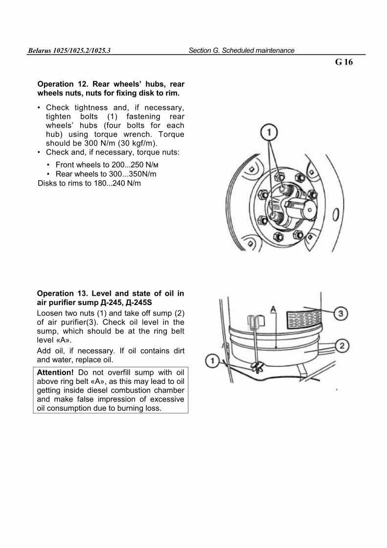
Belarus 1025/1025.2/1025.3 Section G. Scheduled maintenance
G 16
Operation 12. Rear wheels’ hubs, rear wheels nuts, nuts for fixing disk to rim.
• Check tightness and, if necessary, tighten bolts (1) fastening rear wheels’ hubs (four bolts for each hub) using torque wrench. Torque should be 300 N/m (30 kgf/m).
• Check and, if necessary, torque nuts:
• Front wheels to 200...250 N/м • Rear wheels to 300...350N/m
Disks to rims to 180...240 N/m
Operation 13. Level and state of oil in air purifier sump Д-245, Д-245S Loosen two nuts (1) and take off sump (2) of air purifier(3). Check oil level in the sump, which should be at the ring belt level «А». Add oil, if necessary. If oil contains dirt and water, replace oil. Attention! Do not overfill sump with oil above ring belt «А», as this may lead to oil getting inside diesel combustion chamber and make false impression of excessive oil consumption due to burning loss.
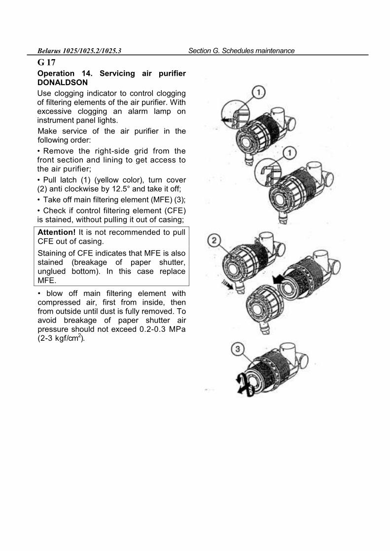
Belarus 1025/1025.2/1025.3 Section G. Schedules maintenance
G 17 Operation 14. Servicing air purifier DONALDSON Use clogging indicator to control clogging of filtering elements of the air purifier. With excessive clogging an alarm lamp on instrument panel lights. Make service of the air purifier in the following order: • Remove the right-side grid from the front section and lining to get access to the air purifier; • Pull latch (1) (yellow color), turn cover (2) anti clockwise by 12.5° and take it off; • Take off main filtering element (MFE) (3); • Check if control filtering element (CFE) is stained, without pulling it out of casing; Attention! It is not recommended to pull CFE out of casing. Staining of CFE indicates that MFE is also stained (breakage of paper shutter, unglued bottom). In this case replace MFE. • blow off main filtering element with compressed air, first from inside, then from outside until dust is fully removed. To avoid breakage of paper shutter air pressure should not exceed 0.2-0.3 MPa (2-3 kgf/cm2).
Belarus 1025/1025.2/1025.3 Section G. Scheduled maintenance
Direct air flow at an angle to the surface of a filtering element. During servicing protect filtering element from mechanical damage and oiling. When filtering element is stained or oiled, and blowing off with air is not efficient, it should be washed in solution of soap paste OP-7 or OP-10 and water heated to temperature of 40-50°С. Solution is prepared at proportion 20 grams of paste per one liter of water. If paste is not available, one may use solution of household detergent with the same concentration. To wash the element, put it in washing solution for thirty minutes, then thoroughly rinse it for 15 minutes in the same solution and them in pure water heated to 35...45°С, and dry up for 24 hours. Do not use open flame and air with temperature above +70°С for drying .
G 18
• make assembly of the air purifier in the reverse order;
Note: Under dusty conditions check state of MFE after each 20 hours of tractor operation.
• put right-side lining grid in place.
Attention! After assembling the air purifier check air tightness of all inlet duct connections. To this end start the diesel and at medium crankshaft rotation speed shut air purifier pipe. Diesel should quickly stop functioning. Otherwise, find out and correct leakage.
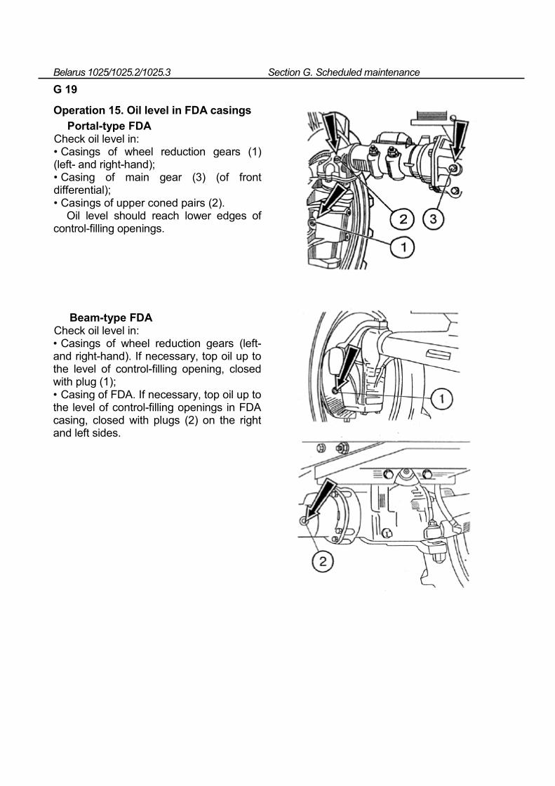
Belarus 1025/1025.2/1025.3 Section G. Scheduled maintenance
G 19
Operation 15. Oil level in FDA casings
Portal-type FDA Check oil level in: • Casings of wheel reduction gears (1) (left- and right-hand); • Casing of main gear (3) (of front differential); • Casings of upper coned pairs (2).
Oil level should reach lower edges of control-filling openings.
Beam-type FDA Check oil level in: • Casings of wheel reduction gears (left- and right-hand). If necessary, top oil up to the level of control-filling opening, closed with plug (1); • Casing of FDA. If necessary, top oil up to the level of control-filling openings in FDA casing, closed with plugs (2) on the right and left sides.
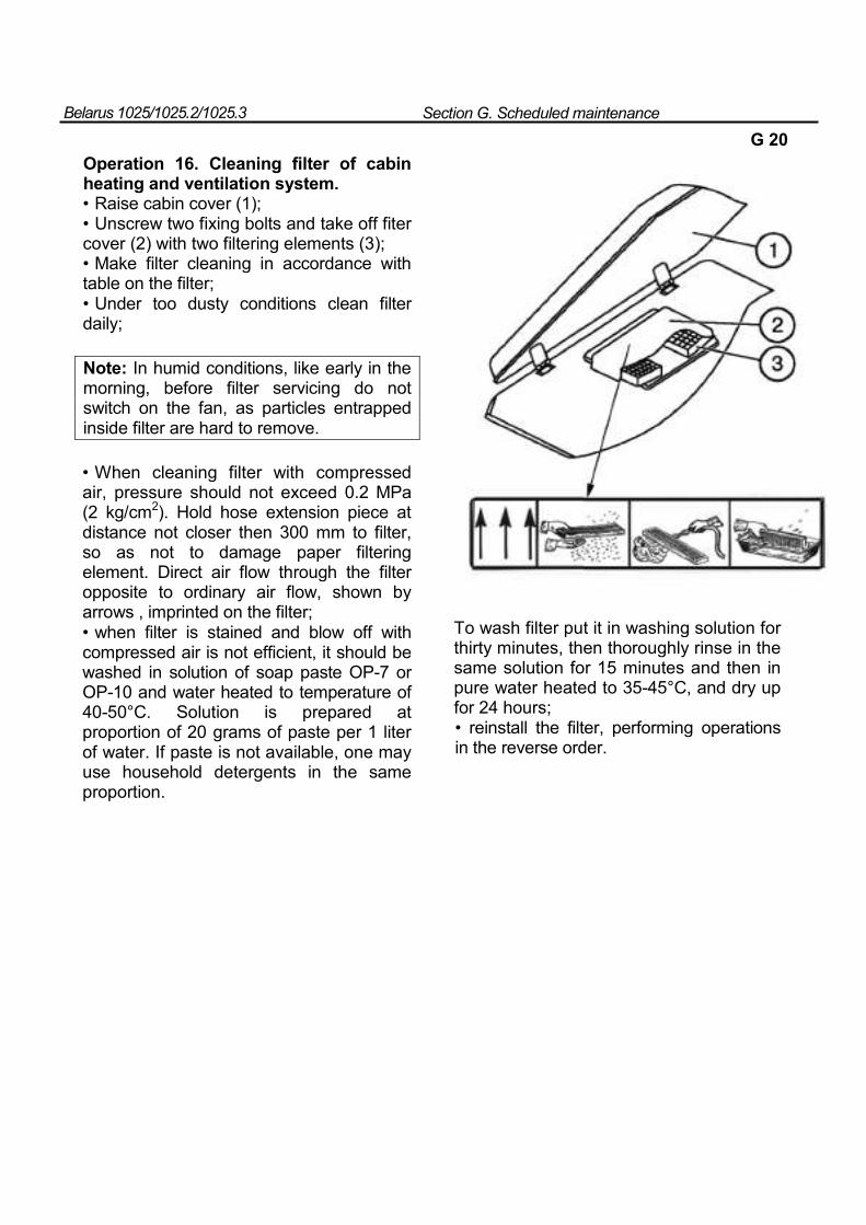
Belarus 1025/1025.2/1025.3 Section G. Scheduled maintenance
G 20
Operation 16. Cleaning filter of cabin heating and ventilation system. • Raise cabin cover (1); • Unscrew two fixing bolts and take off fiter cover (2) with two filtering elements (3); • Make filter cleaning in accordance with table on the filter; • Under too dusty conditions clean filter daily;
Note: In humid conditions, like early in the morning, before filter servicing do not switch on the fan, as particles entrapped inside filter are hard to remove.
• When cleaning filter with compressed air, pressure should not exceed 0.2 MPa (2 kg/cm2). Hold hose extension piece at distance not closer then 300 mm to filter, so as not to damage paper filtering element. Direct air flow through the filter opposite to ordinary air flow, shown by arrows , imprinted on the filter; • when filter is stained and blow off with compressed air is not efficient, it should be washed in solution of soap paste OP-7 or OP-10 and water heated to temperature of 40-50°С. Solution is prepared at proportion of 20 grams of paste per 1 liter of water. If paste is not available, one may use household detergents in the same proportion.
To wash filter put it in washing solution for thirty minutes, then thoroughly rinse in the same solution for 15 minutes and then in pure water heated to 35-45°С, and dry up for 24 hours; • reinstall the filter, performing operations in the reverse order.
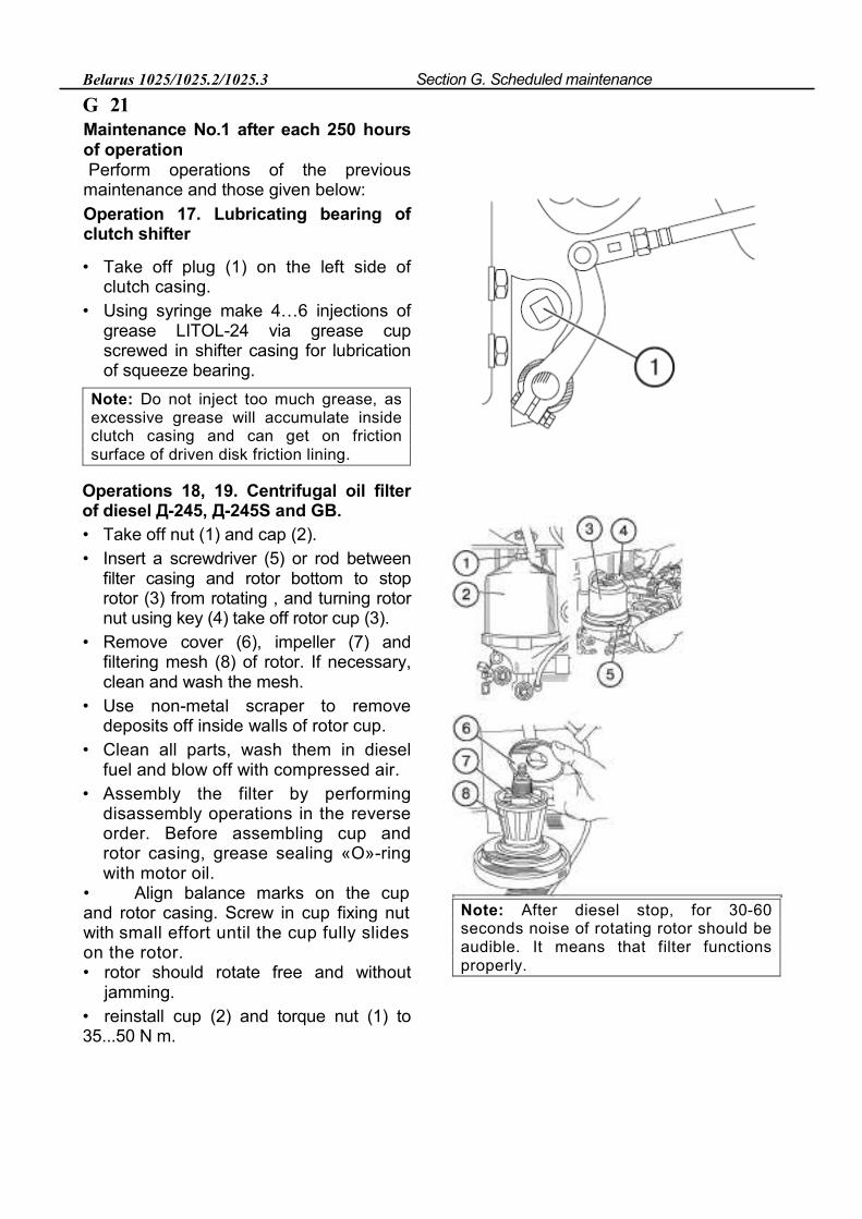
Belarus 1025/1025.2/1025.3 Section G. Scheduled maintenance
G 21 Maintenance No.1 after each 250 hours of operation Perform operations of the previous
maintenance and those given below: Operation 17. Lubricating bearing of clutch shifter
• Take off plug (1) on the left side of clutch casing.
• Using syringe make 4…6 injections of grease LITOL-24 via grease cup screwed in shifter casing for lubrication of squeeze bearing.
Note: Do not inject too much grease, as excessive grease will accumulate inside clutch casing and can get on friction surface of driven disk friction lining.
Operations 18, 19. Centrifugal oil filter of diesel Д-245, Д-245S and GB. • Take off nut (1) and cap (2). • Insert a screwdriver (5) or rod between
filter casing and rotor bottom to stop rotor (3) from rotating , and turning rotor nut using key (4) take off rotor cup (3).
• Remove cover (6), impeller (7) and filtering mesh (8) of rotor. If necessary, clean and wash the mesh.
• Use non-metal scraper to remove deposits off inside walls of rotor cup.
• Clean all parts, wash them in diesel fuel and blow off with compressed air.
• Assembly the filter by performing disassembly operations in the reverse order. Before assembling cup and rotor casing, grease sealing «О»-ring with motor oil.
• Align balance marks on the cup and rotor casing. Screw in cup fixing nut with small effort until the cup fully slides on the rotor. • rotor should rotate free and without
jamming. • reinstall cup (2) and torque nut (1) to 35...50 N m.
Note: After diesel stop, for 30-60 seconds noise of rotating rotor should be audible. It means that filter functions properly.
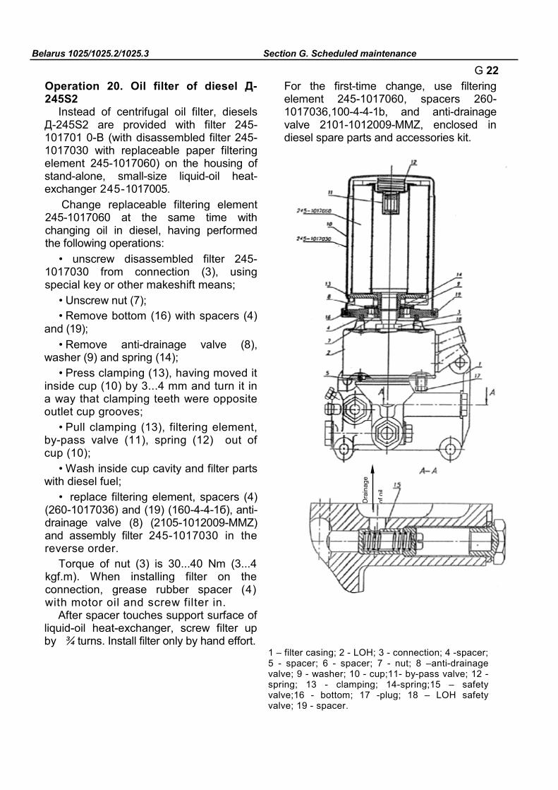
Belarus 1025/1025.2/1025.3 Section G. Scheduled maintenance
G 22 Operation 20. Oil filter of diesel Д-245S2
Instead of centrifugal oil filter, diesels Д-245S2 are provided with filter 245-101701 0-В (with disassembled filter 245-1017030 with replaceable paper filtering element 245-1017060) on the housing of stand-alone, small-size liquid-oil heat-exchanger 245-1017005.
Change replaceable filtering element 245-1017060 at the same time with changing oil in diesel, having performed the following operations:
• unscrew disassembled filter 245-1017030 from connection (3), using special key or other makeshift means;
• Unscrew nut (7); • Remove bottom (16) with spacers (4)
and (19); • Remove anti-drainage valve (8),
washer (9) and spring (14); • Press clamping (13), having moved it
inside cup (10) by 3...4 mm and turn it in a way that clamping teeth were opposite outlet cup grooves;
• Pull clamping (13), filtering element, by-pass valve (11), spring (12) out of cup (10);
• Wash inside cup cavity and filter parts with diesel fuel;
• replace filtering element, spacers (4) (260-1017036) and (19) (160-4-4-1б), anti-drainage valve (8) (2105-1012009-ММZ) and assembly filter 245-1017030 in the reverse order.
Torque of nut (3) is 30...40 Nm (3...4 kgf.m). When installing filter on the connection, grease rubber spacer (4) with motor oil and screw filter in.
After spacer touches support surface of liquid-oil heat-exchanger, screw filter up by ¾ turns. Install filter only by hand effort.
For the first-time change, use filtering element 245-1017060, spacers 260-1017036,100-4-4-1b, and anti-drainage valve 2101-1012009-ММZ, enclosed in diesel spare parts and accessories kit.
1 – filter casing; 2 - LOH; 3 - connection; 4 -spacer; 5 - spacer; 6 - spacer; 7 - nut; 8 –anti-drainage valve; 9 - washer; 10 - cup;11- by-pass valve; 12 - spring; 13 - clamping; 14-spring;15 – safety valve;16 - bottom; 17 -plug; 18 – LOH safety valve; 19 - spacer.
Dra
inag
e of
oil

Belarus 1025/1025.2/1025.3 Section G. Scheduled maintenance
G 23
Instead of built-up filter 245-1017030 with replaceable paper filtering element, one may install permanently sealed filter-cartridges, including anti-drainage and by-pass valves with dimensions in diameter - 95...105 mm; height -140...160 mm; mating thread -3/4-16 UNF.
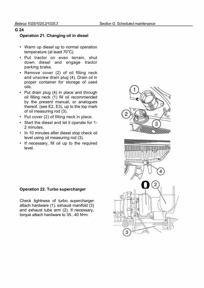
Belarus 1025/1025.2/1025.3 Section G. Scheduled maintenance
G 24
Operation 21. Changing oil in diesel
• Warm up diesel up to normal operation temperature (at least 70°С).
• Put tractor on even terrain, shut down diesel and engage tractor parking brake.
• Remove cover (2) of oil filling neck and unscrew drain plug (4). Drain oil in proper container for storage of used oils.
• Put drain plug (4) in place and through oil filling neck (1) fill oil recommended by the present manual, or analogues thereof. (see E2, E3), up to the top mark of oil measuring rod (3).
• Put cover (2) of filling neck in place. • Start the diesel and let it operate for 1-
2 minutes. • In 10 minutes after diesel stop check oil
level using oil measuring rod (3). • If necessary, fill oil up to the required
level.
Operation 22. Turbo supercharger
Check tightness of turbo supercharger attach hardware (1), exhaust manifold (3) and exhaust tube arm (2). If necessary, torque attach hardware to 35...40 N•m.
0
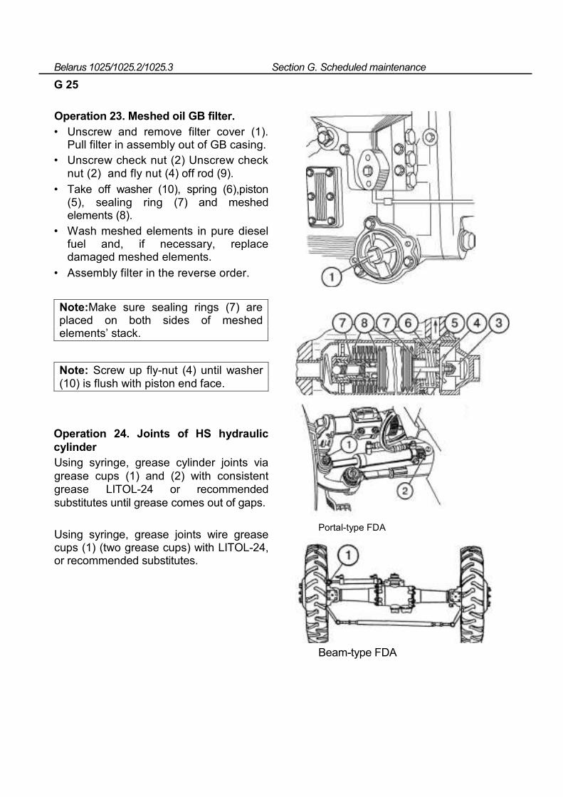
Belarus 1025/1025.2/1025.3 Section G. Scheduled maintenance
G 25
Operation 23. Meshed oil GB filter. • Unscrew and remove filter cover (1).
Pull filter in assembly out of GB casing. • Unscrew check nut (2) Unscrew check
nut (2) and fly nut (4) off rod (9). • Take off washer (10), spring (6),piston
(5), sealing ring (7) and meshed elements (8).
• Wash meshed elements in pure diesel fuel and, if necessary, replace damaged meshed elements.
• Assembly filter in the reverse order.
Note:Make sure sealing rings (7) are placed on both sides of meshed elements’ stack.
Note: Screw up fly-nut (4) until washer (10) is flush with piston end face.
Operation 24. Joints of HS hydraulic cylinder Using syringe, grease cylinder joints via grease cups (1) and (2) with consistent grease LITOL-24 or recommended substitutes until grease comes out of gaps.
Using syringe, grease joints wire grease cups (1) (two grease cups) with LITOL-24, or recommended substitutes.
Portal-type FDA
Beam-type FDA
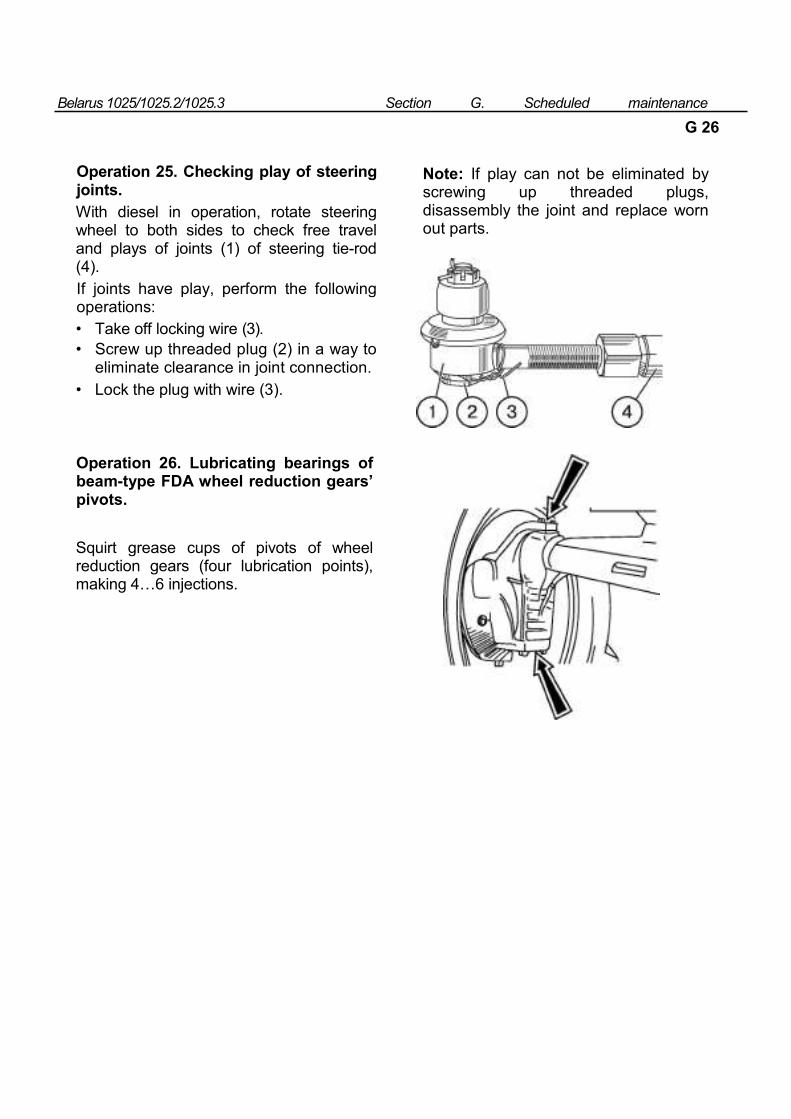
Belarus 1025/1025.2/1025.3 Section G. Scheduled maintenance
G 26
Operation 25. Checking play of steering joints. With diesel in operation, rotate steering wheel to both sides to check free travel and plays of joints (1) of steering tie-rod (4). If joints have play, perform the following operations: • Take off locking wire (3). • Screw up threaded plug (2) in a way to
eliminate clearance in joint connection. • Lock the plug with wire (3).
Note: If play can not be eliminated by screwing up threaded plugs, disassembly the joint and replace worn out parts.
Operation 26. Lubricating bearings of beam-type FDA wheel reduction gears’ pivots.
Squirt grease cups of pivots of wheel reduction gears (four lubrication points), making 4…6 injections.
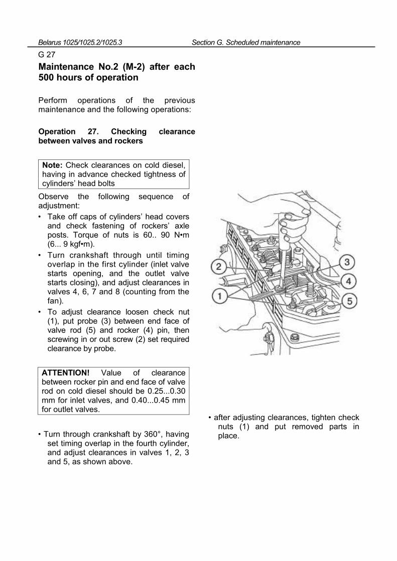
Belarus 1025/1025.2/1025.3 Section G. Scheduled maintenance
G 27
Maintenance No.2 (M-2) after each 500 hours of operation
Perform operations of the previous maintenance and the following operations:
Operation 27. Checking clearance between valves and rockers
Note: Check clearances on cold diesel, having in advance checked tightness of cylinders’ head bolts
Observe the following sequence of adjustment: • Take off caps of cylinders’ head covers
and check fastening of rockers’ axle posts. Torque of nuts is 60.. 90 N•m (6... 9 kgf•m).
• Turn crankshaft through until timing overlap in the first cylinder (inlet valve starts opening, and the outlet valve starts closing), and adjust clearances in valves 4, 6, 7 and 8 (counting from the fan).
• To adjust clearance loosen check nut (1), put probe (3) between end face of valve rod (5) and rocker (4) pin, then screwing in or out screw (2) set required clearance by probe.
ATTENTION! Value of clearance between rocker pin and end face of valve rod on cold diesel should be 0.25...0.30 mm for inlet valves, and 0.40...0.45 mm for outlet valves.
• Turn through crankshaft by 360°, having set timing overlap in the fourth cylinder, and adjust clearances in valves 1, 2, 3 and 5, as shown above.
• after adjusting clearances, tighten check nuts (1) and put removed parts in place.
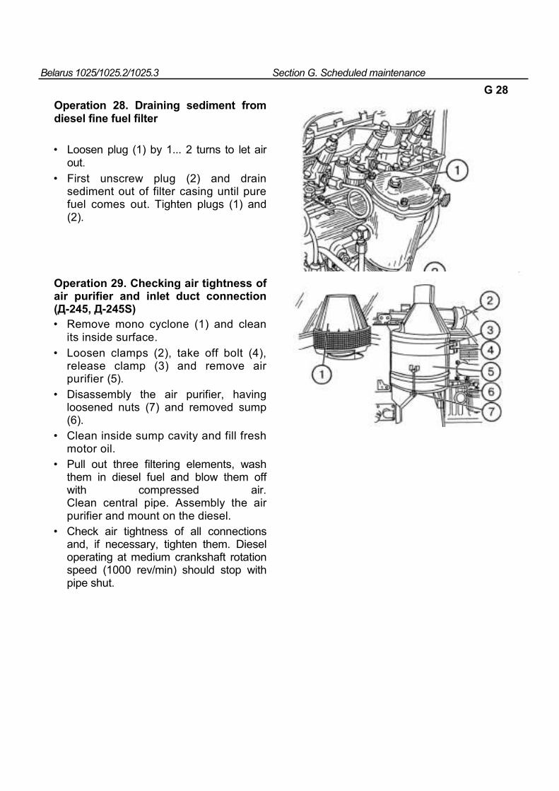
Belarus 1025/1025.2/1025.3 Section G. Scheduled maintenance
G 28 Operation 28. Draining sediment from diesel fine fuel filter
• Loosen plug (1) by 1... 2 turns to let air out.
• First unscrew plug (2) and drain sediment out of filter casing until pure fuel comes out. Tighten plugs (1) and (2).
Operation 29. Checking air tightness of air purifier and inlet duct connection (Д-245, Д-245S) • Remove mono cyclone (1) and clean
its inside surface. • Loosen clamps (2), take off bolt (4),
release clamp (3) and remove air purifier (5).
• Disassembly the air purifier, having loosened nuts (7) and removed sump (6).
• Clean inside sump cavity and fill fresh motor oil.
• Pull out three filtering elements, wash them in diesel fuel and blow them off with compressed air. Clean central pipe. Assembly the air purifier and mount on the diesel.
• Check air tightness of all connections and, if necessary, tighten them. Diesel operating at medium crankshaft rotation speed (1000 rev/min) should stop with pipe shut.
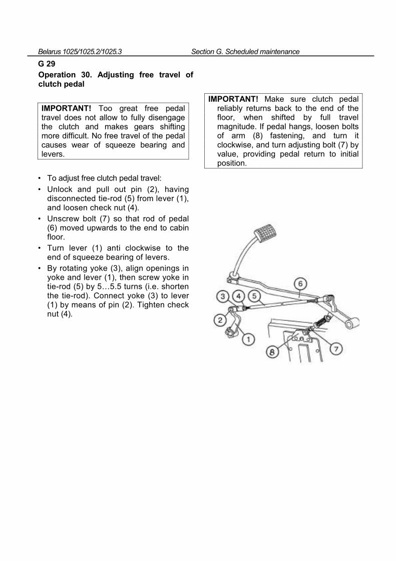
Belarus 1025/1025.2/1025.3 Section G. Scheduled maintenance
G 29 Operation 30. Adjusting free travel of clutch pedal
IMPORTANT! Too great free pedal travel does not allow to fully disengage the clutch and makes gears shifting more difficult. No free travel of the pedal causes wear of squeeze bearing and levers.
• To adjust free clutch pedal travel: • Unlock and pull out pin (2), having
disconnected tie-rod (5) from lever (1), and loosen check nut (4).
• Unscrew bolt (7) so that rod of pedal (6) moved upwards to the end to cabin floor.
• Turn lever (1) anti clockwise to the end of squeeze bearing of levers.
• By rotating yoke (3), align openings in yoke and lever (1), then screw yoke in tie-rod (5) by 5…5.5 turns (i.e. shorten the tie-rod). Connect yoke (3) to lever (1) by means of pin (2). Tighten check nut (4).
IMPORTANT! Make sure clutch pedal reliably returns back to the end of the floor, when shifted by full travel magnitude. If pedal hangs, loosen bolts of arm (8) fastening, and turn it clockwise, and turn adjusting bolt (7) by value, providing pedal return to initial position.
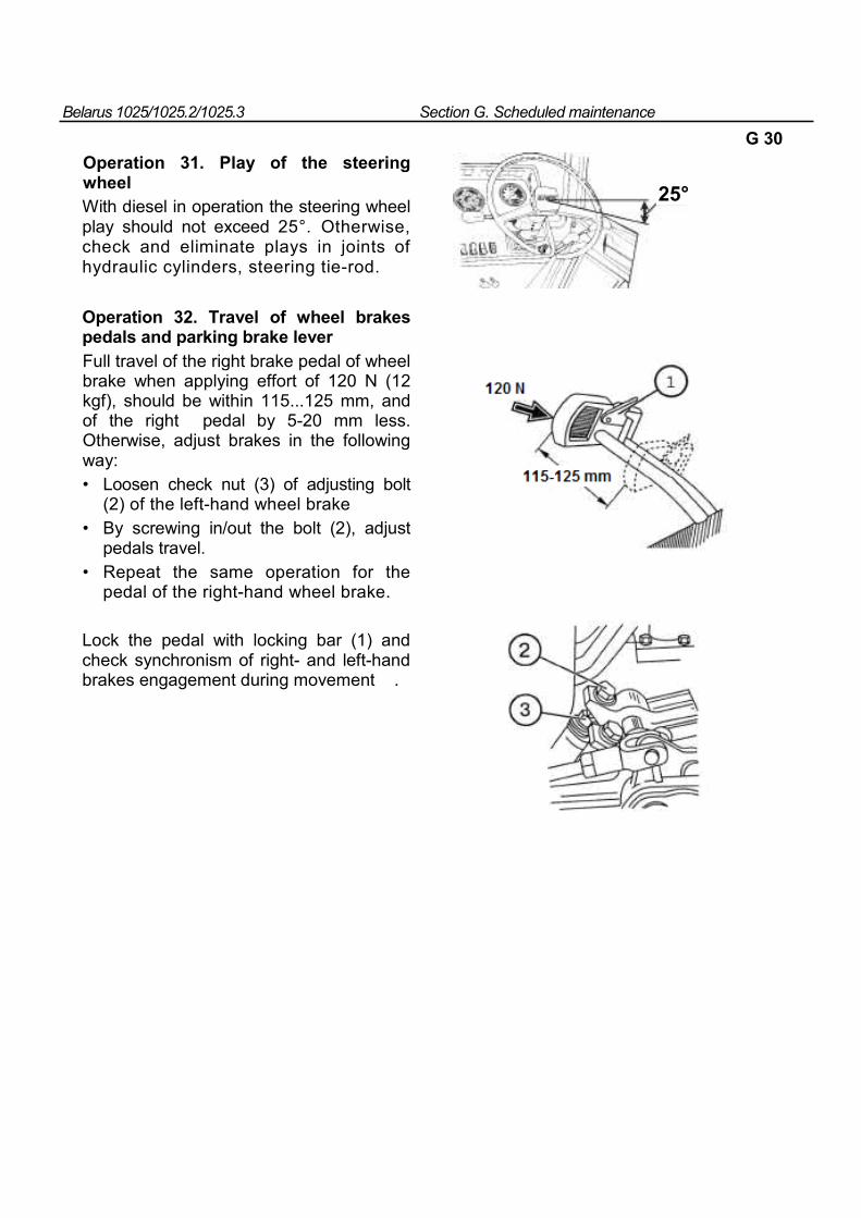
Belarus 1025/1025.2/1025.3 Section G. Scheduled maintenance
G 30
Operation 31. Play of the steering wheel With diesel in operation the steering wheel play should not exceed 25°. Otherwise, check and eliminate plays in joints of hydraulic cylinders, steering tie-rod.
Operation 32. Travel of wheel brakes pedals and parking brake lever
Full travel of the right brake pedal of wheel brake when applying effort of 120 N (12 kgf), should be within 115...125 mm, and of the right pedal by 5-20 mm less. Otherwise, adjust brakes in the following way: • Loosen check nut (3) of adjusting bolt
(2) of the left-hand wheel brake • By screwing in/out the bolt (2), adjust
pedals travel. • Repeat the same operation for the
pedal of the right-hand wheel brake.
Lock the pedal with locking bar (1) and check synchronism of right- and left-hand brakes engagement during movement .
25°
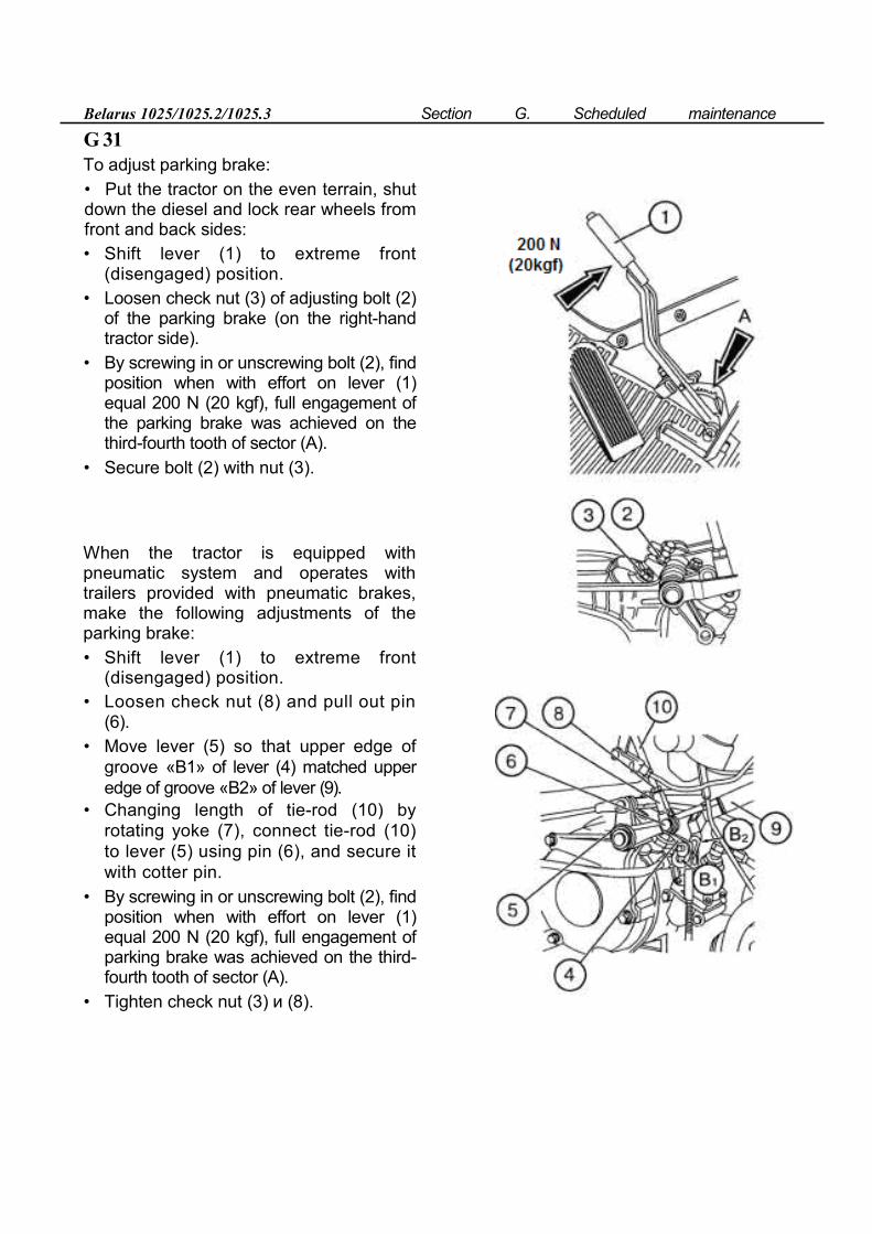
Belarus 1025/1025.2/1025.3 Section G. Scheduled maintenance
G 31
To adjust parking brake: • Put the tractor on the even terrain, shut down the diesel and lock rear wheels from front and back sides: • Shift lever (1) to extreme front
(disengaged) position. • Loosen check nut (3) of adjusting bolt (2)
of the parking brake (on the right-hand tractor side).
• By screwing in or unscrewing bolt (2), find position when with effort on lever (1) equal 200 N (20 kgf), full engagement of the parking brake was achieved on the third-fourth tooth of sector (A).
• Secure bolt (2) with nut (3).
When the tractor is equipped with pneumatic system and operates with trailers provided with pneumatic brakes, make the following adjustments of the parking brake: • Shift lever (1) to extreme front
(disengaged) position. • Loosen check nut (8) and pull out pin
(6). • Move lever (5) so that upper edge of
groove «В1» of lever (4) matched upper edge of groove «В2» of lever (9).
• Changing length of tie-rod (10) by rotating yoke (7), connect tie-rod (10) to lever (5) using pin (6), and secure it with cotter pin.
• By screwing in or unscrewing bolt (2), find position when with effort on lever (1) equal 200 N (20 kgf), full engagement of parking brake was achieved on the third-fourth tooth of sector (А).
• Tighten check nut (3) и (8).
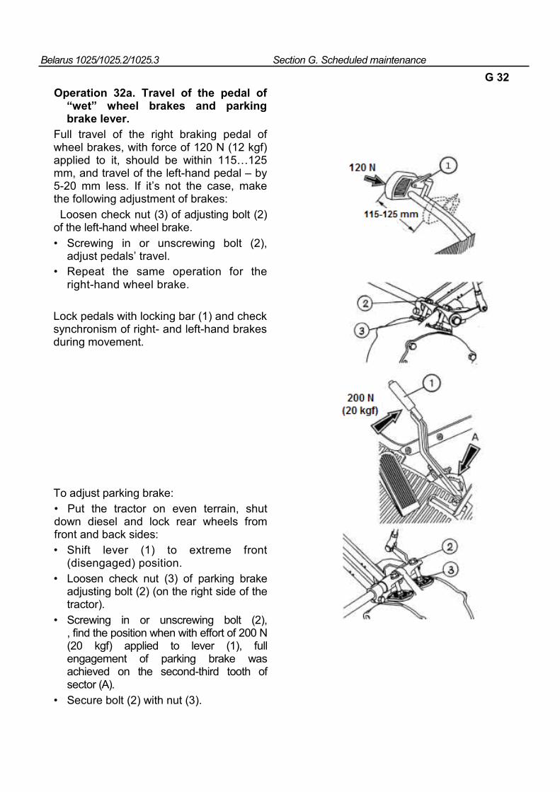
Belarus 1025/1025.2/1025.3 Section G. Scheduled maintenance
G 32 Operation 32а. Travel of the pedal of
“wet” wheel brakes and parking brake lever.
Full travel of the right braking pedal of wheel brakes, with force of 120 N (12 kgf) applied to it, should be within 115…125 mm, and travel of the left-hand pedal – by 5-20 mm less. If it’s not the case, make the following adjustment of brakes: Loosen check nut (3) of adjusting bolt (2) of the left-hand wheel brake. • Screwing in or unscrewing bolt (2),
adjust pedals’ travel. • Repeat the same operation for the
right-hand wheel brake.
Lock pedals with locking bar (1) and check synchronism of right- and left-hand brakes during movement.
To adjust parking brake: • Put the tractor on even terrain, shut down diesel and lock rear wheels from front and back sides: • Shift lever (1) to extreme front
(disengaged) position. • Loosen check nut (3) of parking brake
adjusting bolt (2) (on the right side of the tractor).
• Screwing in or unscrewing bolt (2), , find the position when with effort of 200 N (20 kgf) applied to lever (1), full engagement of parking brake was achieved on the second-third tooth of sector (А).
• Secure bolt (2) with nut (3).
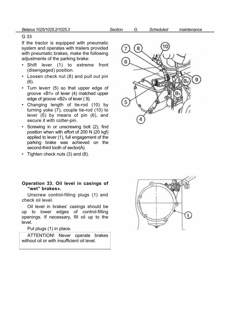
Belarus 1025/1025.2/1025.3 Section G. Scheduled maintenance
G 33 If the tractor is equipped with pneumatic system and operates with trailers provided with pneumatic brakes, make the following adjustments of the parking brake: • Shift lever (1) to extreme front
(disengaged) position. • Loosen check nut (8) and pull out pin
(6). • Turn leverг (5) so that upper edge of
groove «В1» of lever (4) matched upper edge of groove «В2» of lever ( 9).
• Changing length of tie-rod (10) by turning yoke (7), couple tie-rod (10) to lever (5) by means of pin (6), and secure it with cotter-pin.
• Screwing in or unscrewing bolt (2), find position when with effort of 200 N (20 kgf) applied to lever (1), full engagement of the parking brake was achieved on the second-third tooth of sector(А).
• Tighten check nuts (3) and (8).
Operation 33. Oil level in casings of “wet” brakes». Unscrew control-filling plugs (1) and
check oil level. Oil level in brakes’ casings should be
up to lower edges of control-filling openings. If necessary, fill oil up to the level.
Put plugs (1) in place. ATTENTION! Never operate brakes
without oil or with insufficient oil level.
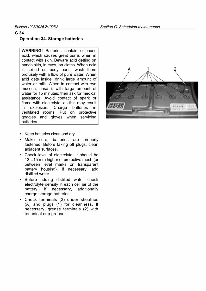
Belarus 1025/1025.2/1025.3 Section G. Scheduled maintenance
G 34
Operation 34. Storage batteries
WARNING! Batteries contain sulphuric acid, which causes great burns when in contact with skin. Beware acid getting on hands skin, in eyes, on cloths. When acid is spilled on body parts, wash them profusely with a flow of pure water. When acid gets inside, drink large amount of water or milk. When in contact with eye mucosa, rinse it with large amount of water for 15 minutes, then ask for medical assistance. Avoid contact of spark or flame with electrolyte, as this may result in explosion. Charge batteries in ventilated rooms. Put on protective goggles and gloves when servicing batteries.
• Keep batteries clean and dry. • Make sure, batteries are properly
fastened. Before taking off plugs, clean adjacent surfaces.
• Check level of electrolyte. It should be 12…15 mm higher of protective mesh (or between level marks on transparent battery housing). If necessary, add distilled water.
• Before adding distilled water check electrolyte density in each cell jar of the battery. If necessary, additionally charge storage batteries.
• Check terminals (2) under sheathes (A) and plugs (1) for cleanness. If necessary, grease terminals (2) with technical cup grease.
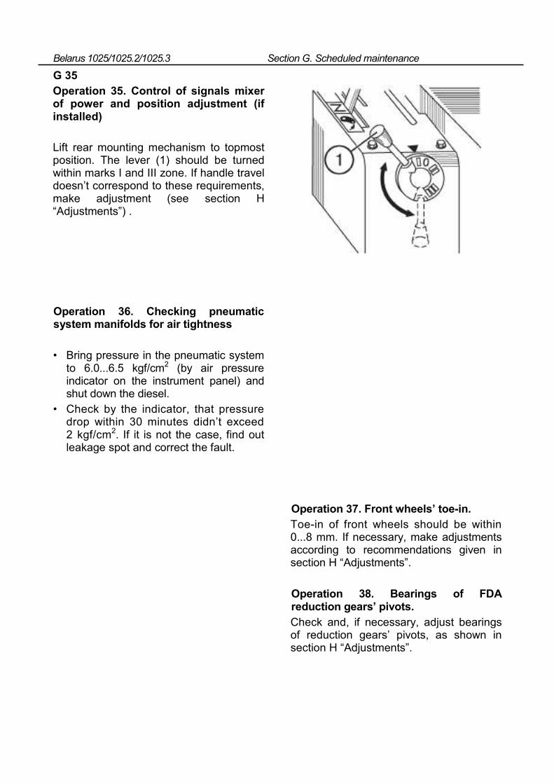
Belarus 1025/1025.2/1025.3 Section G. Scheduled maintenance
G 35 Operation 35. Control of signals mixer of power and position adjustment (if installed)
Lift rear mounting mechanism to topmost position. The lever (1) should be turned within marks I and III zone. If handle travel doesn’t correspond to these requirements, make adjustment (see section H “Adjustments”) .
Operation 36. Checking pneumatic system manifolds for air tightness
• Bring pressure in the pneumatic system to 6.0...6.5 kgf/cm2 (by air pressure indicator on the instrument panel) and shut down the diesel.
• Check by the indicator, that pressure drop within 30 minutes didn’t exceed 2 kgf/cm2. If it is not the case, find out leakage spot and correct the fault.
Operation 37. Front wheels’ toe-in. Toe-in of front wheels should be within 0...8 mm. If necessary, make adjustments according to recommendations given in section H “Adjustments”.
Operation 38. Bearings of FDA reduction gears’ pivots. Check and, if necessary, adjust bearings of reduction gears’ pivots, as shown in section H “Adjustments”.
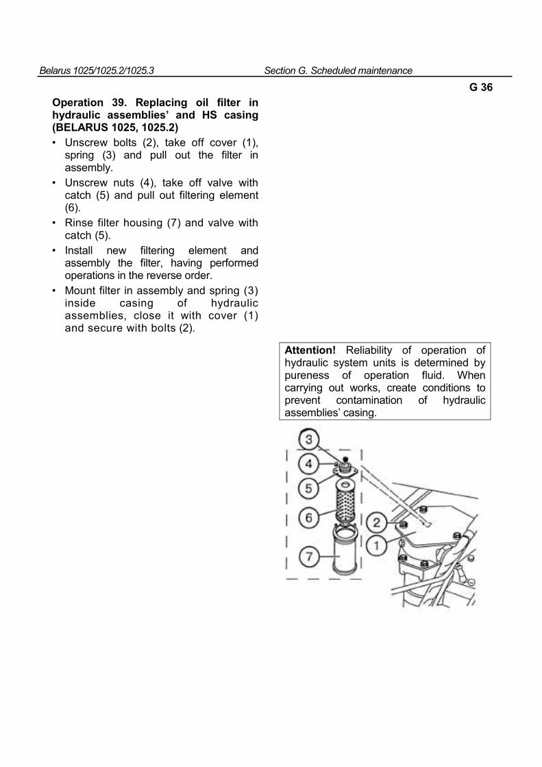
Belarus 1025/1025.2/1025.3 Section G. Scheduled maintenance
G 36
Operation 39. Replacing oil filter in hydraulic assemblies’ and HS casing (BELARUS 1025, 1025.2) • Unscrew bolts (2), take off cover (1),
spring (3) and pull out the filter in assembly.
• Unscrew nuts (4), take off valve with catch (5) and pull out filtering element (6).
• Rinse filter housing (7) and valve with catch (5).
• Install new filtering element and assembly the filter, having performed operations in the reverse order.
• Mount filter in assembly and spring (3) inside casing of hydraulic assemblies, close it with cover (1) and secure with bolts (2).
Attention! Reliability of operation of hydraulic system units is determined by pureness of operation fluid. When carrying out works, create conditions to prevent contamination of hydraulic assemblies’ casing.
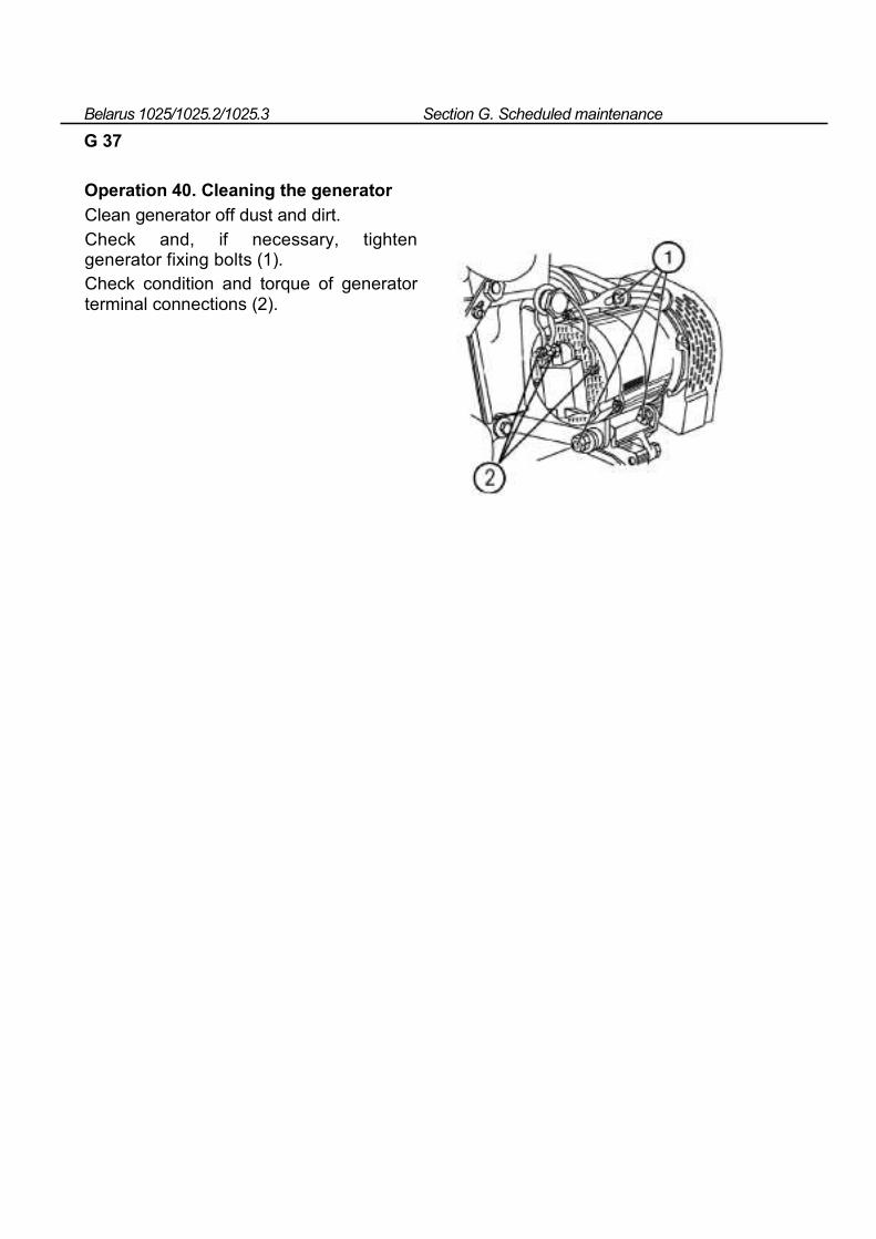
Belarus 1025/1025.2/1025.3 Section G. Scheduled maintenance
G 37
Operation 40. Cleaning the generator
Clean generator off dust and dirt. Check and, if necessary, tighten generator fixing bolts (1). Check condition and torque of generator terminal connections (2).
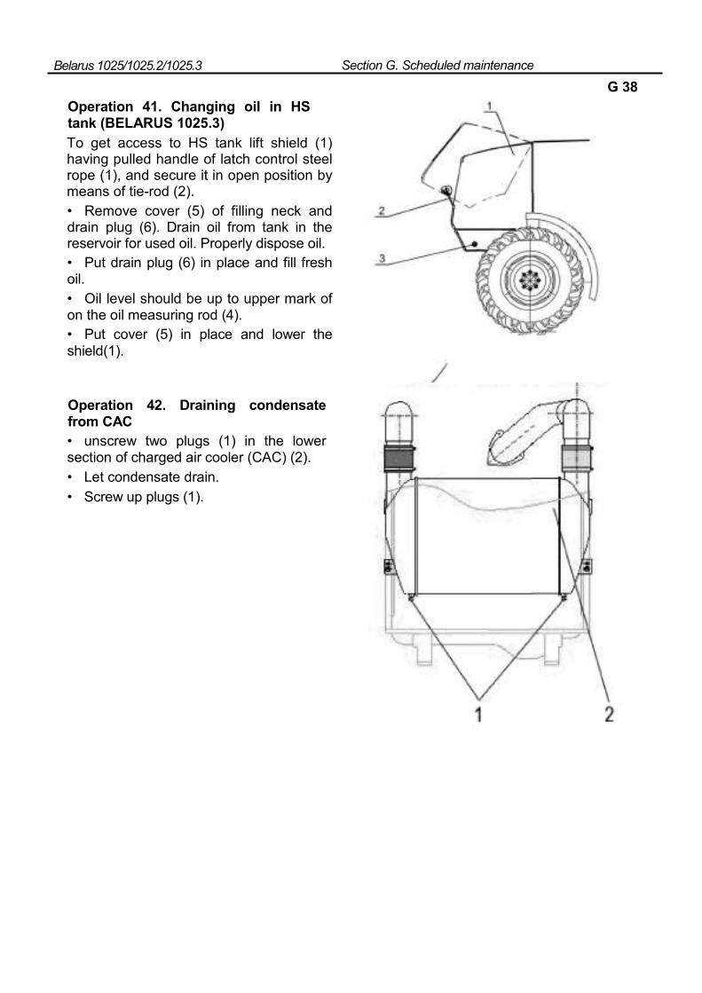
Belarus 1025/1025.2/1025.3 Section G. Scheduled maintenance
G 38
Operation 41. Changing oil in HS tank (BELARUS 1025.3) To get access to HS tank lift shield (1) having pulled handle of latch control steel rope (1), and secure it in open position by means of tie-rod (2). • Remove cover (5) of filling neck and drain plug (6). Drain oil from tank in the reservoir for used oil. Properly dispose oil. • Put drain plug (6) in place and fill fresh oil. • Oil level should be up to upper mark of on the oil measuring rod (4). • Put cover (5) in place and lower the shield(1).
Operation 42. Draining condensate from CAC • unscrew two plugs (1) in the lower section of charged air cooler (CAC) (2). • Let condensate drain. • Screw up plugs (1).
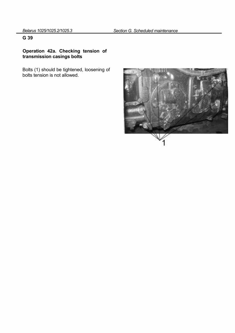
Belarus 1025/1025.2/1025.3 Section G. Scheduled maintenance
G 39
Operation 42а. Checking tension of transmission casings bolts
Bolts (1) should be tightened, loosening of bolts tension is not allowed.
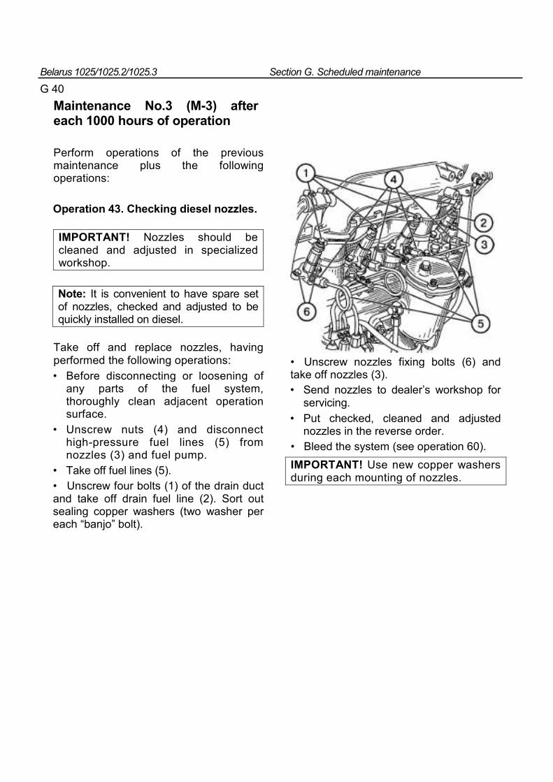
Belarus 1025/1025.2/1025.3 Section G. Scheduled maintenance
G 40
Maintenance No.3 (M-3) after each 1000 hours of operation
Perform operations of the previous maintenance plus the following operations:
Operation 43. Checking diesel nozzles.
IMPORTANT! Nozzles should be cleaned and adjusted in specialized workshop.
Note: It is convenient to have spare set of nozzles, checked and adjusted to be quickly installed on diesel.
Take off and replace nozzles, having performed the following operations: • Before disconnecting or loosening of
any parts of the fuel system, thoroughly clean adjacent operation surface.
• Unscrew nuts (4) and disconnect high-pressure fuel lines (5) from nozzles (3) and fuel pump.
• Take off fuel lines (5). • Unscrew four bolts (1) of the drain duct and take off drain fuel line (2). Sort out sealing copper washers (two washer per each “banjo” bolt).
• Unscrew nozzles fixing bolts (6) and take off nozzles (3). • Send nozzles to dealer’s workshop for
servicing. • Put checked, cleaned and adjusted
nozzles in the reverse order. • Bleed the system (see operation 60). IMPORTANT! Use new copper washers during each mounting of nozzles.
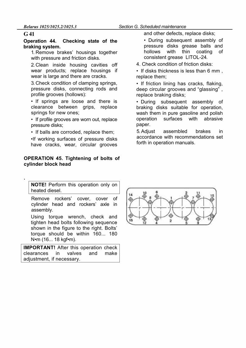
Belarus 1025/1025.2/1025.3 Section G. Scheduled maintenance
G 41 Operation 44. Checking state of the braking system.
1. Remove brakes’ housings together with pressure and friction disks. 2. Clean inside housing cavities off wear products; replace housings if wear is large and there are cracks. 3. Check condition of clamping springs, pressure disks, connecting rods and profile grooves (hollows): • If springs are loose and there is clearance between grips, replace springs for new ones; • If profile grooves are worn out, replace pressure disks; • If balls are corroded, replace them; •If working surfaces of pressure disks have cracks, wear, circular grooves
and other defects, replace disks; • During subsequent assembly of pressure disks grease balls and hollows with thin coating of consistent grease LITOL-24.
4. Check condition of friction disks: • If disks thickness is less than 6 mm , replace them; • If friction lining has cracks, flaking, deep circular grooves and “glassing” , replace braking disks; • During subsequent assembly of braking disks suitable for operation, wash them in pure gasoline and polish operation surfaces with abrasive paper. 5. Adjust assembled brakes in accordance with recommendations set forth in operation manuals.
OPERATION 45. Tightening of bolts of cylinder block head
.
NOTE! Perform this operation only on heated diesel. Remove rockers’ cover, cover of cylinder head and rockers’ axle in assembly. Using torque wrench, check and tighten head bolts following sequence shown in the figure to the right. Bolts’ torque should be within 160... 180 N•m (16... 18 kgf•m).
IMPORTANT! After this operation check clearances in valves and make adjustment, if necessary.
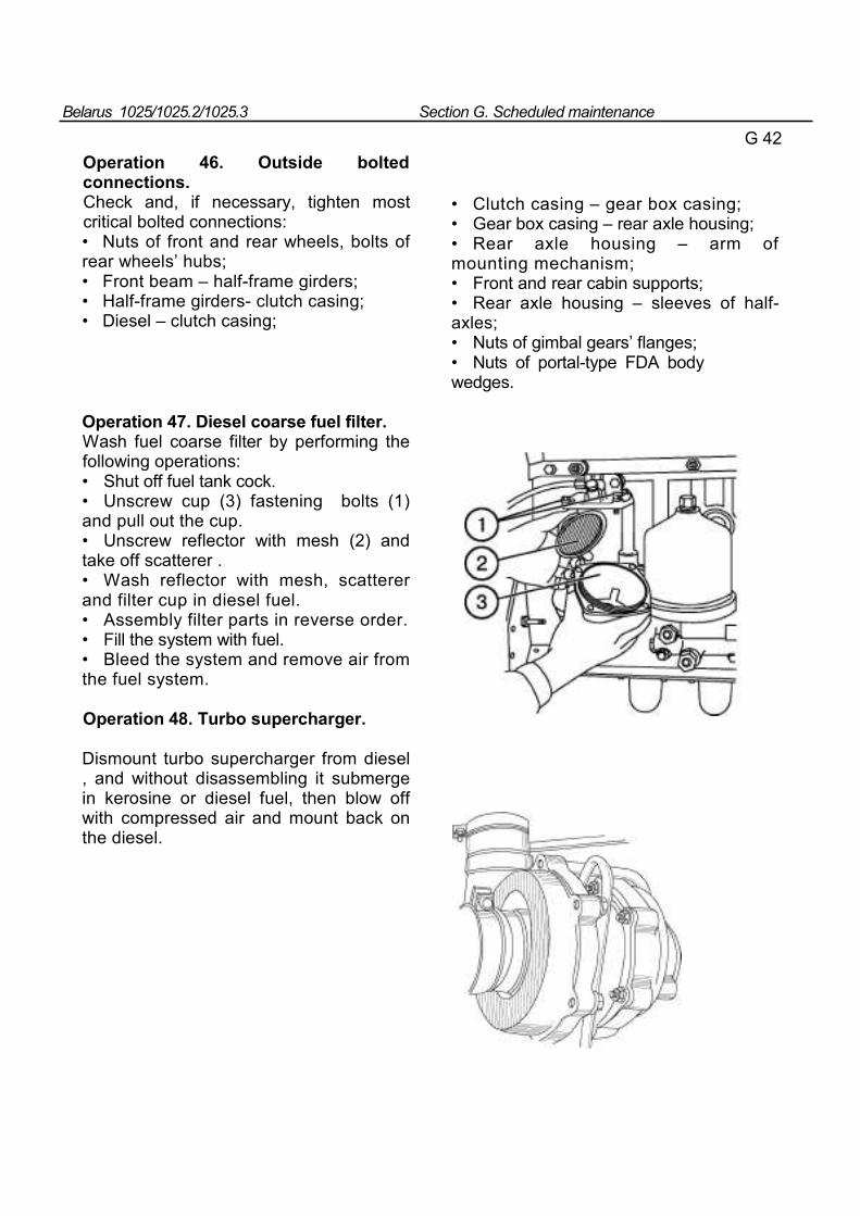
Belarus 1025/1025.2/1025.3 Section G. Scheduled maintenance
G 42
Operation 46. Outside bolted connections. Check and, if necessary, tighten most critical bolted connections: • Nuts of front and rear wheels, bolts of rear wheels’ hubs; • Front beam – half-frame girders; • Half-frame girders- clutch casing; • Diesel – clutch casing;
• Clutch casing – gear box casing; • Gear box casing – rear axle housing; • Rear axle housing – arm of mounting mechanism; • Front and rear cabin supports; • Rear axle housing – sleeves of half-axles; • Nuts of gimbal gears’ flanges; • Nuts of portal-type FDA body wedges.
Operation 47. Diesel coarse fuel filter. Wash fuel coarse filter by performing the following operations: • Shut off fuel tank cock. • Unscrew cup (3) fastening bolts (1) and pull out the cup. • Unscrew reflector with mesh (2) and take off scatterer . • Wash reflector with mesh, scatterer and filter cup in diesel fuel. • Assembly filter parts in reverse order. • Fill the system with fuel. • Bleed the system and remove air from the fuel system.
Operation 48. Turbo supercharger.
Dismount turbo supercharger from diesel , and without disassembling it submerge in kerosine or diesel fuel, then blow off with compressed air and mount back on the diesel.
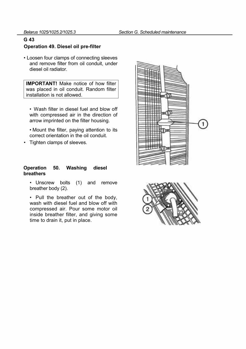
Belarus 1025/1025.2/1025.3 Section G. Scheduled maintenance
G 43 Operation 49. Diesel oil pre-filter
• Loosen four clamps of connecting sleeves and remove filter from oil conduit, under diesel oil radiator.
IMPORTANT! Make notice of how filter was placed in oil conduit. Random filter installation is not allowed.
• Wash filter in diesel fuel and blow off with compressed air in the direction of arrow imprinted on the filter housing.
• Mount the filter, paying attention to its correct orientation in the oil conduit.
• Tighten clamps of sleeves.
Operation 50. Washing diesel breathers
• Unscrew bolts (1) and remove breather body (2).
• Pull the breather out of the body, wash with diesel fuel and blow off with compressed air. Pour some motor oil inside breather filter, and giving some time to drain it, put in place.
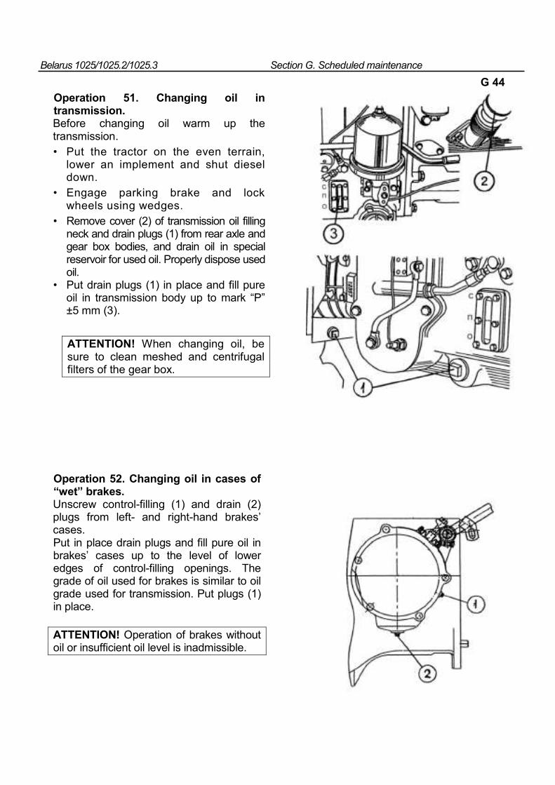
Belarus 1025/1025.2/1025.3 Section G. Scheduled maintenance
G 44
Operation 51. Changing oil in transmission. Before changing oil warm up the transmission. • Put the tractor on the even terrain,
lower an implement and shut diesel down.
• Engage parking brake and lock wheels using wedges.
• Remove cover (2) of transmission oil filling neck and drain plugs (1) from rear axle and gear box bodies, and drain oil in special reservoir for used oil. Properly dispose used oil.
• Put drain plugs (1) in place and fill pure oil in transmission body up to mark “P” ±5 mm (3).
ATTENTION! When changing oil, be sure to clean meshed and centrifugal filters of the gear box.
Operation 52. Changing oil in cases of “wet” brakes. Unscrew control-filling (1) and drain (2) plugs from left- and right-hand brakes’ cases. Put in place drain plugs and fill pure oil in brakes’ cases up to the level of lower edges of control-filling openings. The grade of oil used for brakes is similar to oil grade used for transmission. Put plugs (1) in place.
ATTENTION! Operation of brakes without oil or insufficient oil level is inadmissible.
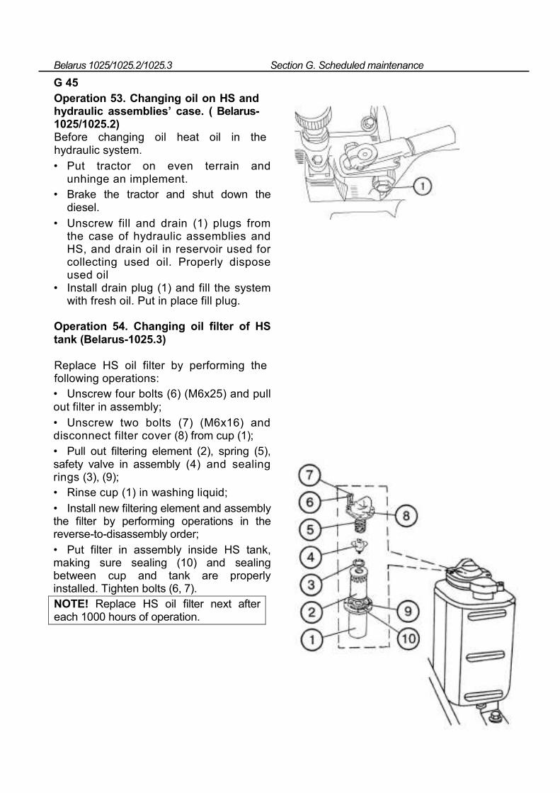
Belarus 1025/1025.2/1025.3 Section G. Scheduled maintenance
G 45 Operation 53. Changing oil on HS and hydraulic assemblies’ case. ( Belarus-1025/1025.2) Before changing oil heat oil in the hydraulic system. • Put tractor on even terrain and
unhinge an implement. • Brake the tractor and shut down the
diesel. • Unscrew fill and drain (1) plugs from
the case of hydraulic assemblies and HS, and drain oil in reservoir used for collecting used oil. Properly dispose used oil
• Install drain plug (1) and fill the system with fresh oil. Put in place fill plug.
Operation 54. Changing oil filter of HS tank (Belarus-1025.3)
Replace HS oil filter by performing the following operations: • Unscrew four bolts (6) (М6х25) and pull out filter in assembly; • Unscrew two bolts (7) (М6х16) and disconnect filter cover (8) from cup (1); • Pull out filtering element (2), spring (5), safety valve in assembly (4) and sealing rings (3), (9); • Rinse cup (1) in washing liquid; • Install new filtering element and assembly the filter by performing operations in the reverse-to-disassembly order; • Put filter in assembly inside HS tank, making sure sealing (10) and sealing between cup and tank are properly installed. Tighten bolts (6, 7). NOTE! Replace HS oil filter next after each 1000 hours of operation.
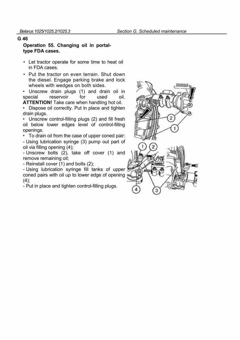
Belarus 1025/1025.2/1025.3 Section G. Scheduled maintenance
G 46 Operation 55. Changing oil in portal-type FDA cases.
• Let tractor operate for some time to heat oil in FDA cases.
• Put the tractor on even terrain. Shut down the diesel. Engage parking brake and lock wheels with wedges on both sides.
• Unscrew drain plugs (1) and drain oil in special reservoir for used oil. ATTENTION! Take care when handling hot oil. • Dispose oil correctly. Put in place and tighten drain plugs. • Unscrew control-filling plugs (2) and fill fresh oil below lower edges level of control-filling openings. • To drain oil from the case of upper coned pair:
- Using lubrication syringe (3) pump out part of oil via filling opening (4); - Unscrew bolts (2), take off cover (1) and remove remaining oil; - Reinstall cover (1) and bolts (2); - Using lubrication syringe fill tanks of upper coned pairs with oil up to lower edge of opening (4); - Put in place and tighten control-filling plugs.
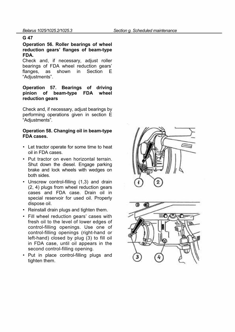
Belarus 1025/1025.2/1025.3 Section g. Scheduled maintenance
G 47 Operation 56. Roller bearings of wheel reduction gears’ flanges of beam-type FDA. Check and, if necessary, adjust roller bearings of FDA wheel reduction gears’ flanges, as shown in Section E “Adjustments”.
Operation 57. Bearings of driving pinion of beam-type FDA wheel reduction gears
Check and, if necessary, adjust bearings by performing operations given in section E “Adjustments”.
Operation 58. Changing oil in beam-type FDA cases.
• Let tractor operate for some time to heat oil in FDA cases.
• Put tractor on even horizontal terrain. Shut down the diesel. Engage parking brake and lock wheels with wedges on both sides.
• Unscrew control-filling (1,3) and drain (2, 4) plugs from wheel reduction gears cases and FDA case. Drain oil in special reservoir for used oil. Properly dispose oil.
• Reinstall drain plugs and tighten them. • Fill wheel reduction gears’ cases with
fresh oil to the level of lower edges of control-filling openings. Use one of control-filling openings (right-hand or left-hand) closed by plug (3) to fill oil in FDA case, until oil appears in the second control-filling opening.
• Put in place control-filling plugs and tighten them.
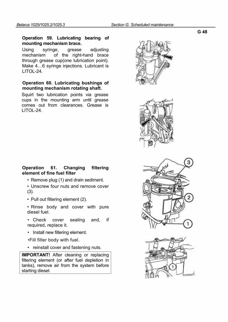
Belarus 1025/1025.2/1025.3 Section G. Scheduled maintenance
G 48
Operation 59. Lubricating bearing of mounting mechanism brace. Using syringe, grease adjusting mechanism of the right-hand brace through grease cup(one lubrication point). Make 4…6 syringe injections. Lubricant is LITOL-24.
Operation 60. Lubricating bushings of mounting mechanism rotating shaft. Squirt two lubrication points via grease cups in the mounting arm until grease comes out from clearances. Grease is LITOL-24.
Operation 61. Changing filtering element of fine fuel filter
• Remove plug (1) and drain sediment. • Unscrew four nuts and remove cover (3).
• Pull out filtering element (2). • Rinse body and cover with pure diesel fuel.
• Check cover sealing and, if required, replace it. • Install new filtering element. •Fill filter body with fuel. • reinstall cover and fastening nuts.
IMPORTANT! After cleaning or replacing filtering element (or after fuel depletion in tanks), remove air from the system before starting diesel.
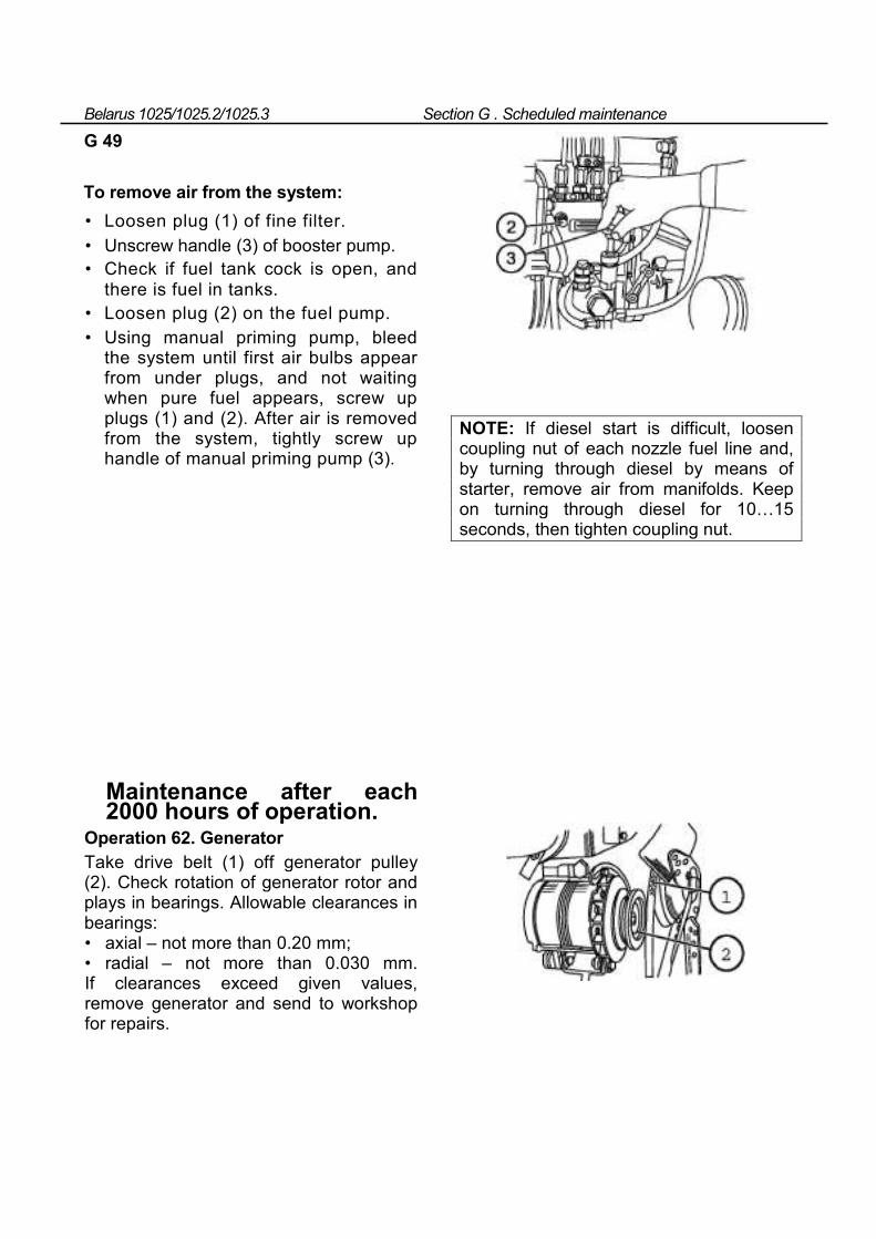
Belarus 1025/1025.2/1025.3 Section G . Scheduled maintenance
G 49
To remove air from the system: • Loosen plug (1) of fine filter. • Unscrew handle (3) of booster pump. • Check if fuel tank cock is open, and
there is fuel in tanks. • Loosen plug (2) on the fuel pump. • Using manual priming pump, bleed
the system until first air bulbs appear from under plugs, and not waiting when pure fuel appears, screw up plugs (1) and (2). After air is removed from the system, tightly screw up handle of manual priming pump (3).
NOTE: If diesel start is difficult, loosen coupling nut of each nozzle fuel line and, by turning through diesel by means of starter, remove air from manifolds. Keep on turning through diesel for 10…15 seconds, then tighten coupling nut.
Maintenance after each 2000 hours of operation.
Operation 62. Generator Take drive belt (1) off generator pulley (2). Check rotation of generator rotor and plays in bearings. Allowable clearances in bearings: • axial – not more than 0.20 mm; • radial – not more than 0.030 mm. If clearances exceed given values, remove generator and send to workshop for repairs.
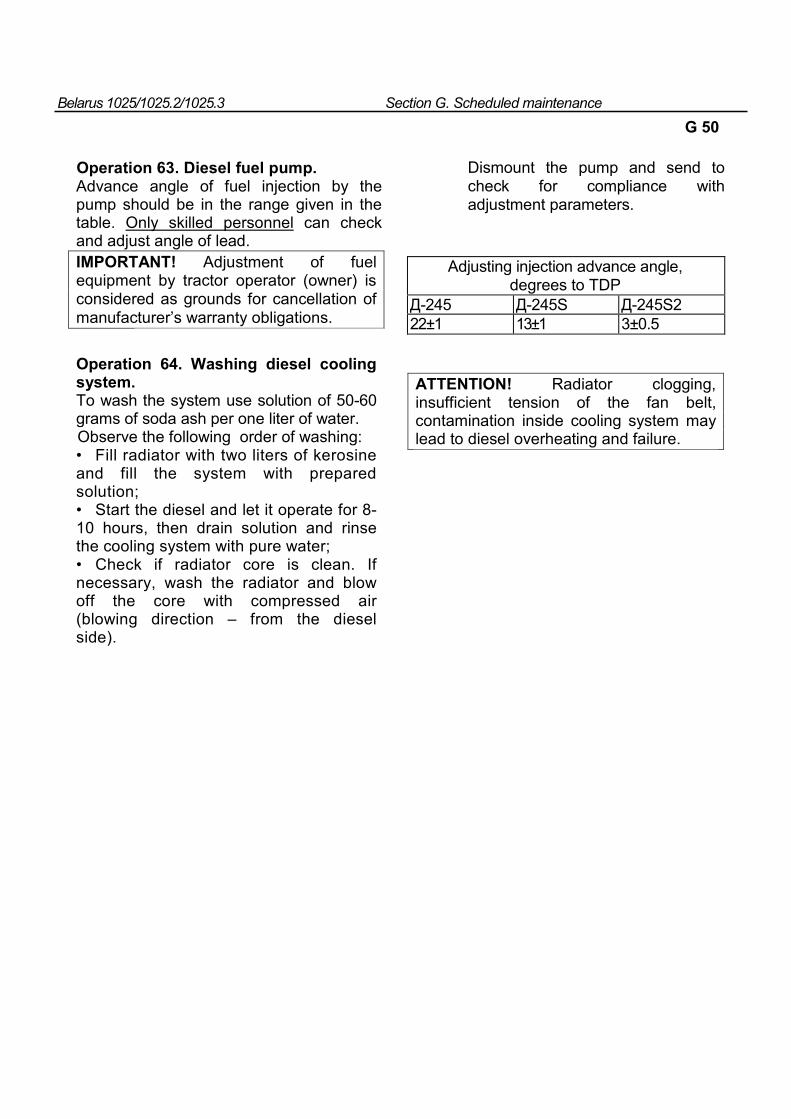
Belarus 1025/1025.2/1025.3 Section G. Scheduled maintenance
G 50
Operation 63. Diesel fuel pump. Advance angle of fuel injection by the pump should be in the range given in the table. Only skilled personnel can check and adjust angle of lead. IMPORTANT! Adjustment of fuel equipment by tractor operator (owner) is considered as grounds for cancellation of manufacturer’s warranty obligations.
Dismount the pump and send to check for compliance with adjustment parameters.
Adjusting injection advance angle, degrees to TDP
Д-245 Д-245S Д-245S2 22±1 13±1 3±0.5
Operation 64. Washing diesel cooling system. To wash the system use solution of 50-60 grams of soda ash per one liter of water. Observe the following order of washing: • Fill radiator with two liters of kerosine and fill the system with prepared solution; • Start the diesel and let it operate for 8-10 hours, then drain solution and rinse the cooling system with pure water; • Check if radiator core is clean. If necessary, wash the radiator and blow off the core with compressed air (blowing direction – from the diesel side).
ATTENTION! Radiator clogging, insufficient tension of the fan belt, contamination inside cooling system may lead to diesel overheating and failure.
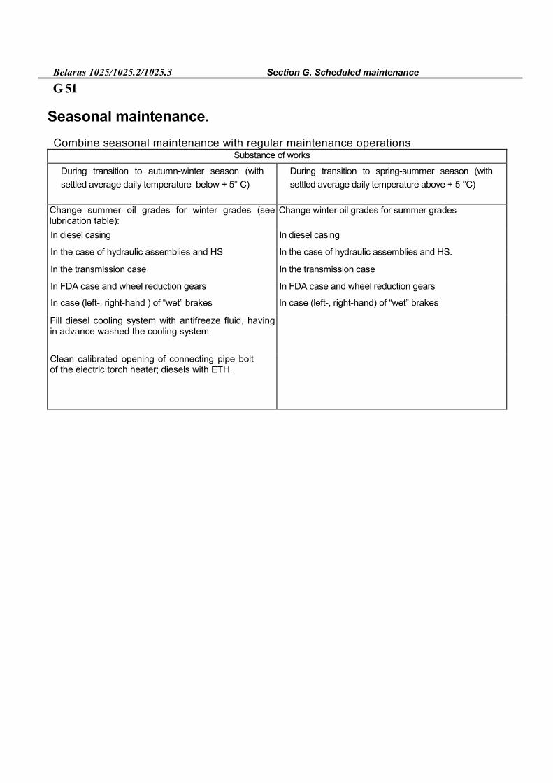
Belarus 1025/1025.2/1025.3 Section G. Scheduled maintenance
G 51
Seasonal maintenance. Combine seasonal maintenance with regular maintenance operations
Substance of works
During transition to autumn-winter season (with settled average daily temperature below + 5° С)
During transition to spring-summer season (with settled average daily temperature above + 5 °С)
Change summer oil grades for winter grades (see lubrication table):
Change winter oil grades for summer grades
In diesel casing In diesel casing
In the case of hydraulic assemblies and HS In the case of hydraulic assemblies and HS.
In the transmission case In the transmission case
In FDA case and wheel reduction gears In FDA case and wheel reduction gears
In case (left-, right-hand ) of “wet” brakes In case (left-, right-hand) of “wet” brakes
Fill diesel cooling system with antifreeze fluid, having in advance washed the cooling system
Clean calibrated opening of connecting pipe bolt of the electric torch heater; diesels with ETH.
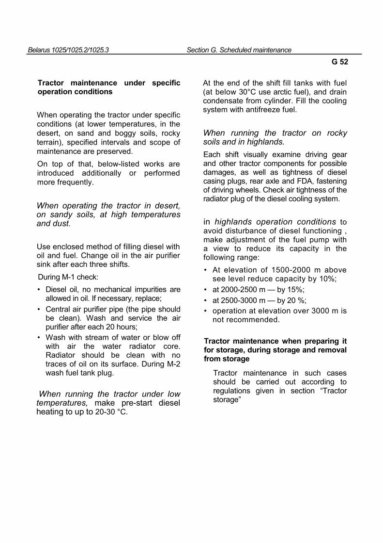
Belarus 1025/1025.2/1025.3 Section G. Scheduled maintenance
G 52
Tractor maintenance under specific operation conditions
When operating the tractor under specific conditions (at lower temperatures, in the desert, on sand and boggy soils, rocky terrain), specified intervals and scope of maintenance are preserved. On top of that, below-listed works are introduced additionally or performed more frequently.
When operating the tractor in desert, on sandy soils, at high temperatures and dust.
Use enclosed method of filling diesel with oil and fuel. Change oil in the air purifier sink after each three shifts. During M-1 check: • Diesel oil, no mechanical impurities are
allowed in oil. If necessary, replace; • Central air purifier pipe (the pipe should
be clean). Wash and service the air purifier after each 20 hours;
• Wash with stream of water or blow off with air the water radiator core. Radiator should be clean with no traces of oil on its surface. During M-2 wash fuel tank plug.
When running the tractor under low temperatures, make pre-start diesel heating to up to 20-30 °С.
At the end of the shift fill tanks with fuel (at below 30°С use arctic fuel), and drain condensate from cylinder. Fill the cooling system with antifreeze fuel.
When running the tractor on rocky soils and in highlands. Each shift visually examine driving gear and other tractor components for possible damages, as well as tightness of diesel casing plugs, rear axle and FDA, fastening of driving wheels. Check air tightness of the radiator plug of the diesel cooling system.
in highlands operation conditions to avoid disturbance of diesel functioning , make adjustment of the fuel pump with a view to reduce its capacity in the following range: • At elevation of 1500-2000 m above
see level reduce capacity by 10%; • at 2000-2500 m — by 15%; • at 2500-3000 m — by 20 %; • operation at elevation over 3000 m is
not recommended.
Tractor maintenance when preparing it for storage, during storage and removal from storage
Tractor maintenance in such cases should be carried out according to regulations given in section “Tractor storage”
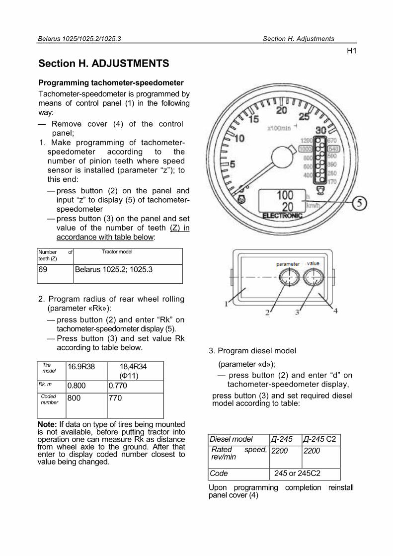
Belarus 1025/1025.2/1025.3 Section H. Adjustments
H1
Section H. ADJUSTMENTS
Programming tachometer-speedometer
Tachometer-speedometer is programmed by means of control panel (1) in the following way: — Remove cover (4) of the control
panel; 1. Make programming of tachometer-
speedometer according to the number of pinion teeth where speed sensor is installed (parameter “z”); to this end: — press button (2) on the panel and
input “z” to display (5) of tachometer-speedometer
— press button (3) on the panel and set value of the number of teeth (Z) in accordance with table below:
Number of teeth (Z)
Tractor model
69 Belarus 1025.2; 1025.3
2. Program radius of rear wheel rolling (parameter «Rk»): — press button (2) and enter “Rk” on
tachometer-speedometer display (5). — Press button (3) and set value Rk
according to table below.
Tire model 16.9R38 18,4R34
(Ф11) Rk, m 0.800 0.770 Coded number 800 770
3. Program diesel model
(parameter «d»); — press button (2) and enter “d” on
tachometer-speedometer display, press button (3) and set required diesel model according to table:
Note: If data on type of tires being mounted is not available, before putting tractor into operation one can measure Rk as distance from wheel axle to the ground. After that enter to display coded number closest to value being changed.
Diesel model Д-245 Д-245 С2 Rated speed, rev/min
2200 2200
Code 245 or 245С2
Upon programming completion reinstall panel cover (4)
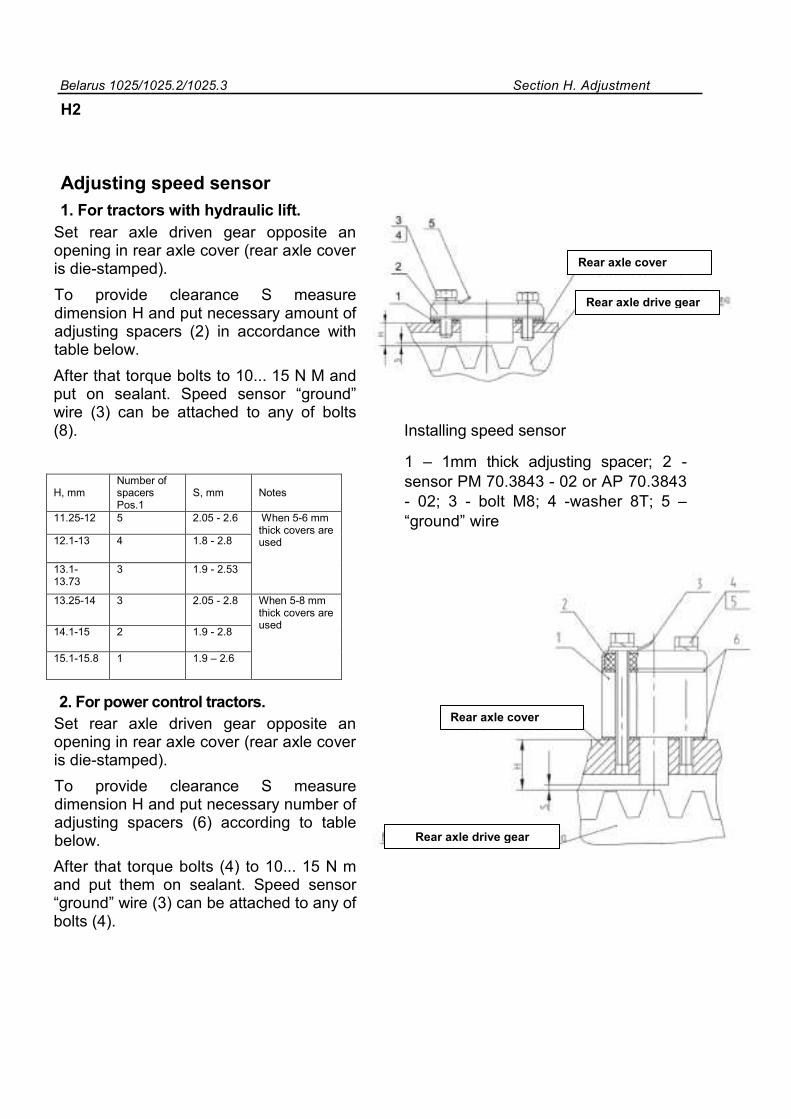
Belarus 1025/1025.2/1025.3 Section H. Adjustment
H2
Adjusting speed sensor
1. For tractors with hydraulic lift. Set rear axle driven gear opposite an opening in rear axle cover (rear axle cover is die-stamped). To provide clearance S measure dimension H and put necessary amount of adjusting spacers (2) in accordance with table below. After that torque bolts to 10... 15 N M and put on sealant. Speed sensor “ground” wire (3) can be attached to any of bolts (8). Installing speed sensor
1 – 1mm thick adjusting spacer; 2 - sensor РМ 70.3843 - 02 or АР 70.3843 - 02; 3 - bolt М8; 4 -washer 8Т; 5 –“ground” wire
2. For power control tractors.
Set rear axle driven gear opposite an opening in rear axle cover (rear axle cover is die-stamped). To provide clearance S measure dimension H and put necessary number of adjusting spacers (6) according to table below. After that torque bolts (4) to 10... 15 N m and put them on sealant. Speed sensor “ground” wire (3) can be attached to any of bolts (4).
H, mm
Number of spacers Pos.1
S, mm
Notes
11.25-12 5 2.05 - 2.6 When 5-6 mm thick covers are used 12.1-13 4 1.8 - 2.8
13.1-13.73
3 1.9 - 2.53
13.25-14 3 2.05 - 2.8 When 5-8 mm thick covers are used 14.1-15 2 1.9 - 2.8
15.1-15.8 1 1.9 – 2.6
Rear axle cover
Rear axle drive gear
Rear axle cover
Rear axle drive gear
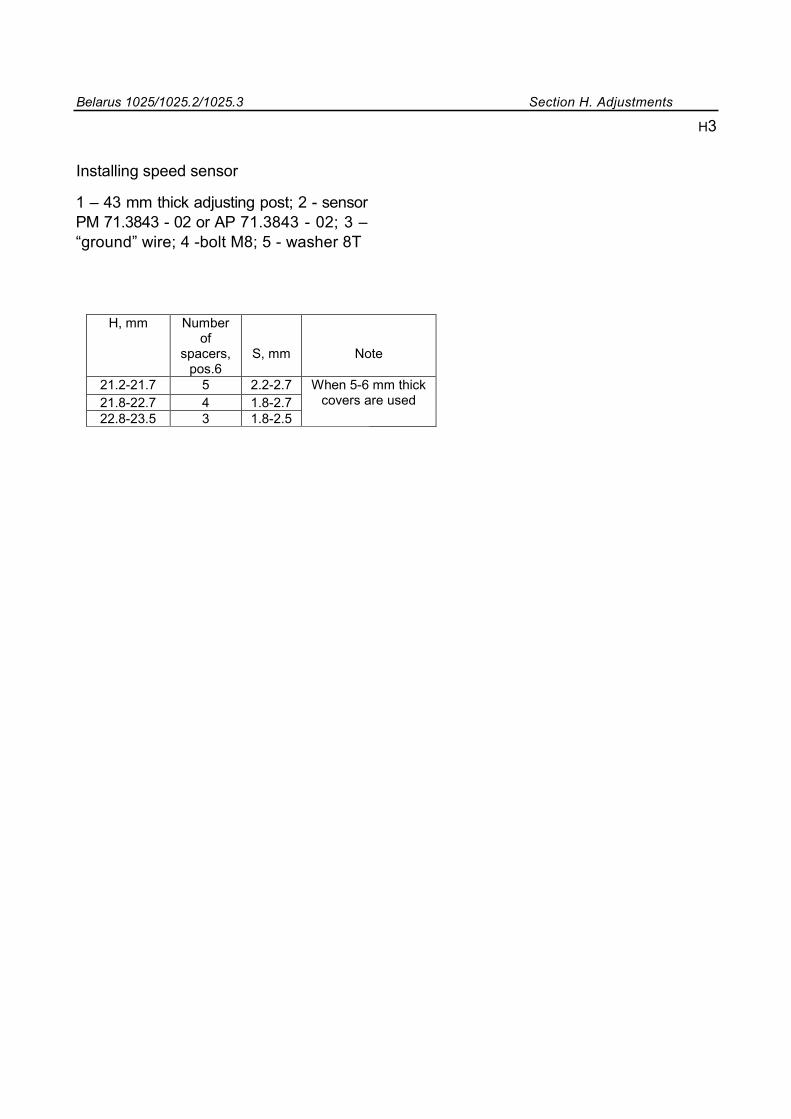
Belarus 1025/1025.2/1025.3 Section H. Adjustments
Installing speed sensor
1 – 43 mm thick adjusting post; 2 - sensor РМ 71.3843 - 02 or АР 71.3843 - 02; 3 –“ground” wire; 4 -bolt М8; 5 - washer 8Т
H, mm Number
of spacers,
pos.6
S, mm
Note
21.2-21.7 5 2.2-2.7 When 5-6 mm thick covers are used 21.8-22.7 4 1.8-2.7
22.8-23.5 3 1.8-2.5
H3
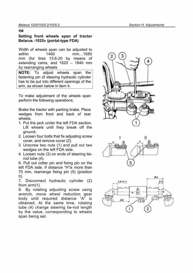
Belarus 1025/1025.2/1025.3 Section H. Adjustments
H4 Setting front wheels span of tractor Belarus -1025» (portal-type FDA)
Width of wheels span can be adjusted to within 1460 mm…1680 mm (for tires 13.6-20 by means of extending cams, and 1620 – 1840 mm by rearranging wheels NOTE: To adjust wheels span the fastening pin of steering hydraulic cylinder has to be put into different openings of the arm, as shown below in item 4.
To make adjustment of the wheels span perform the following operations;
Brake the tractor with parking brake. Place wedges from front and back of rear wheels. 1. Put the jack under the left FDA section.
Lift wheels until they break off the ground.
2. Loosen four bolts that fix adjusting screw cover, and remove cover (2).
3. Unscrew two nuts (1) and pull out two wedges on the left FDA side.
4. Loosen nuts (3) on ends of steering tie-rod tube (4).
6. Pull out cotter pin and fixing pin on the left FDA side. If distance “H”is more than 70 mm, rearrange fixing pin (5) (position II). 7. Disconnect hydraulic cylinder (2) from arm(1). 8. By rotating adjusting screw using wrench, move wheel reduction gear body until required distance “A” is obtained. At the same time, rotating tube (4) change steering tie-rod length by the value, corresponding to wheels span being set.
Ui=Ln
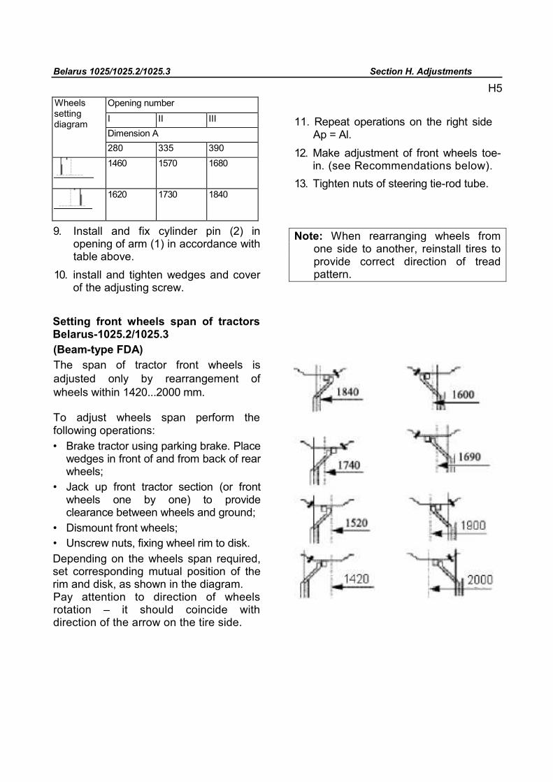
Belarus 1025/1025.2/1025.3 Section H. Adjustments
H5 Wheels setting diagram
Opening number
I II III Dimension А 280 335 390
1460 1570 1680
1620 1730 1840
11. Repeat operations on the right side Ap = Al.
12. Make adjustment of front wheels toe-in. (see Recommendations below).
13. Tighten nuts of steering tie-rod tube.
9. Install and fix cylinder pin (2) in opening of arm (1) in accordance with table above.
10. install and tighten wedges and cover of the adjusting screw.
Note: When rearranging wheels from one side to another, reinstall tires to provide correct direction of tread pattern.
Setting front wheels span of tractors Belarus-1025.2/1025.3 (Beam-type FDA) The span of tractor front wheels is adjusted only by rearrangement of wheels within 1420...2000 mm.
To adjust wheels span perform the following operations: • Brake tractor using parking brake. Place
wedges in front of and from back of rear wheels;
• Jack up front tractor section (or front wheels one by one) to provide clearance between wheels and ground;
• Dismount front wheels; • Unscrew nuts, fixing wheel rim to disk. Depending on the wheels span required, set corresponding mutual position of the rim and disk, as shown in the diagram. Pay attention to direction of wheels rotation – it should coincide with direction of the arrow on the tire side.
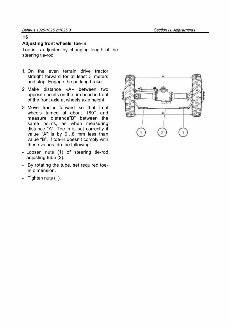
Belarus 1025/1025.2/1025.3 Section H. Adjustments
H6 Adjusting front wheels’ toe-in Toe-in is adjusted by changing length of the steering tie-rod.
1. On the even terrain drive tractor straight forward for at least 3 meters and stop. Engage the parking brake.
2. Make distance «А» between two opposite points on the rim bead in front of the front axle at wheels axle height.
3. Move tractor forward so that front wheels turned at about 180° and measure distance”В” between the same points, as when measuring distance “A”. Toe-in is set correctly if value “A” is by 0…8 mm less than value “B”. If toe-in doesn’t comply with these values, do the following:
- Loosen nuts (1) of steering tie-rod adjusting tube (2).
- By rotating the tube, set required toe-in dimension.
- Tighten nuts (1).
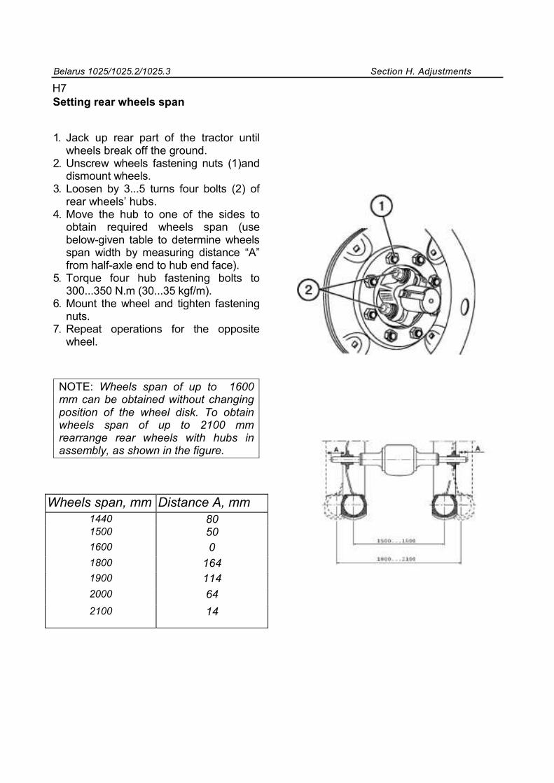
Belarus 1025/1025.2/1025.3 Section H. Adjustments
H7 Setting rear wheels span
1. Jack up rear part of the tractor until wheels break off the ground.
2. Unscrew wheels fastening nuts (1)and dismount wheels.
3. Loosen by 3...5 turns four bolts (2) of rear wheels’ hubs.
4. Move the hub to one of the sides to obtain required wheels span (use below-given table to determine wheels span width by measuring distance “A” from half-axle end to hub end face).
5. Torque four hub fastening bolts to 300...350 N.m (30...35 kgf/m).
6. Mount the wheel and tighten fastening nuts.
7. Repeat operations for the opposite wheel.
NOTE: Wheels span of up to 1600 mm can be obtained without changing position of the wheel disk. To obtain wheels span of up to 2100 mm rearrange rear wheels with hubs in assembly, as shown in the figure.
Wheels span, mm Distance А, mm
1440 80 1500 50 1600 0 1800 164 1900 114 2000 64
2100 14
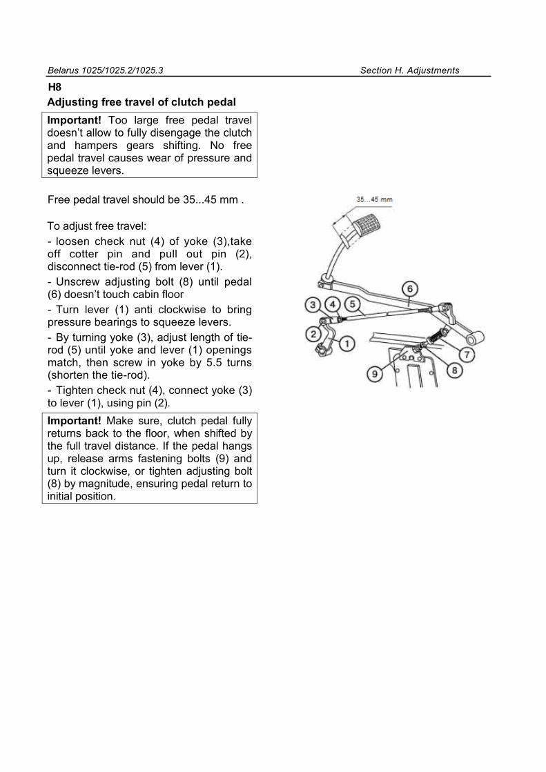
Belarus 1025/1025.2/1025.3 Section H. Adjustments
H8 Adjusting free travel of clutch pedal Important! Too large free pedal travel doesn’t allow to fully disengage the clutch and hampers gears shifting. No free pedal travel causes wear of pressure and squeeze levers.
Free pedal travel should be 35...45 mm .
To adjust free travel: - loosen check nut (4) of yoke (3),take off cotter pin and pull out pin (2), disconnect tie-rod (5) from lever (1). - Unscrew adjusting bolt (8) until pedal (6) doesn’t touch cabin floor - Turn lever (1) anti clockwise to bring pressure bearings to squeeze levers. - By turning yoke (3), adjust length of tie-rod (5) until yoke and lever (1) openings match, then screw in yoke by 5.5 turns (shorten the tie-rod). - Tighten check nut (4), connect yoke (3) to lever (1), using pin (2). Important! Make sure, clutch pedal fully returns back to the floor, when shifted by the full travel distance. If the pedal hangs up, release arms fastening bolts (9) and turn it clockwise, or tighten adjusting bolt (8) by magnitude, ensuring pedal return to initial position.
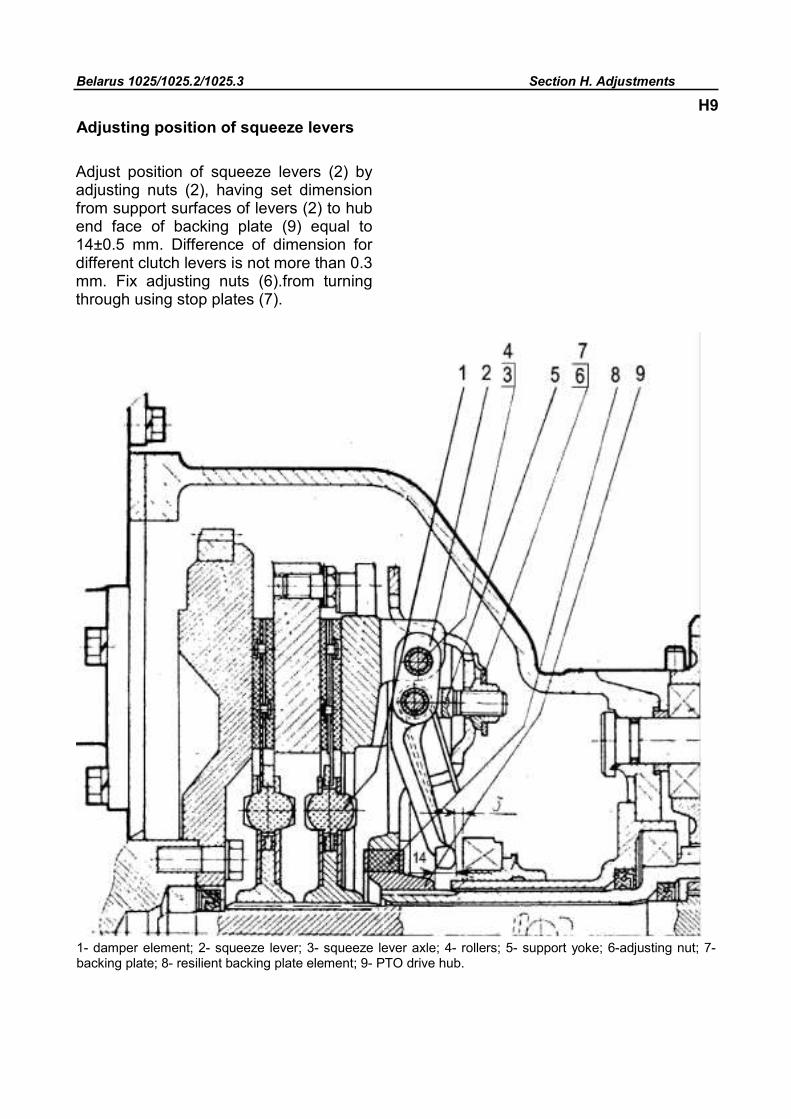
Belarus 1025/1025.2/1025.3 Section H. Adjustments
Adjusting position of squeeze levers
Adjust position of squeeze levers (2) by adjusting nuts (2), having set dimension from support surfaces of levers (2) to hub end face of backing plate (9) equal to 14±0.5 mm. Difference of dimension for different clutch levers is not more than 0.3 mm. Fix adjusting nuts (6).from turning through using stop plates (7).
1- damper element; 2- squeeze lever; 3- squeeze lever axle; 4- rollers; 5- support yoke; 6-adjusting nut; 7- backing plate; 8- resilient backing plate element; 9- PTO drive hub.
H9
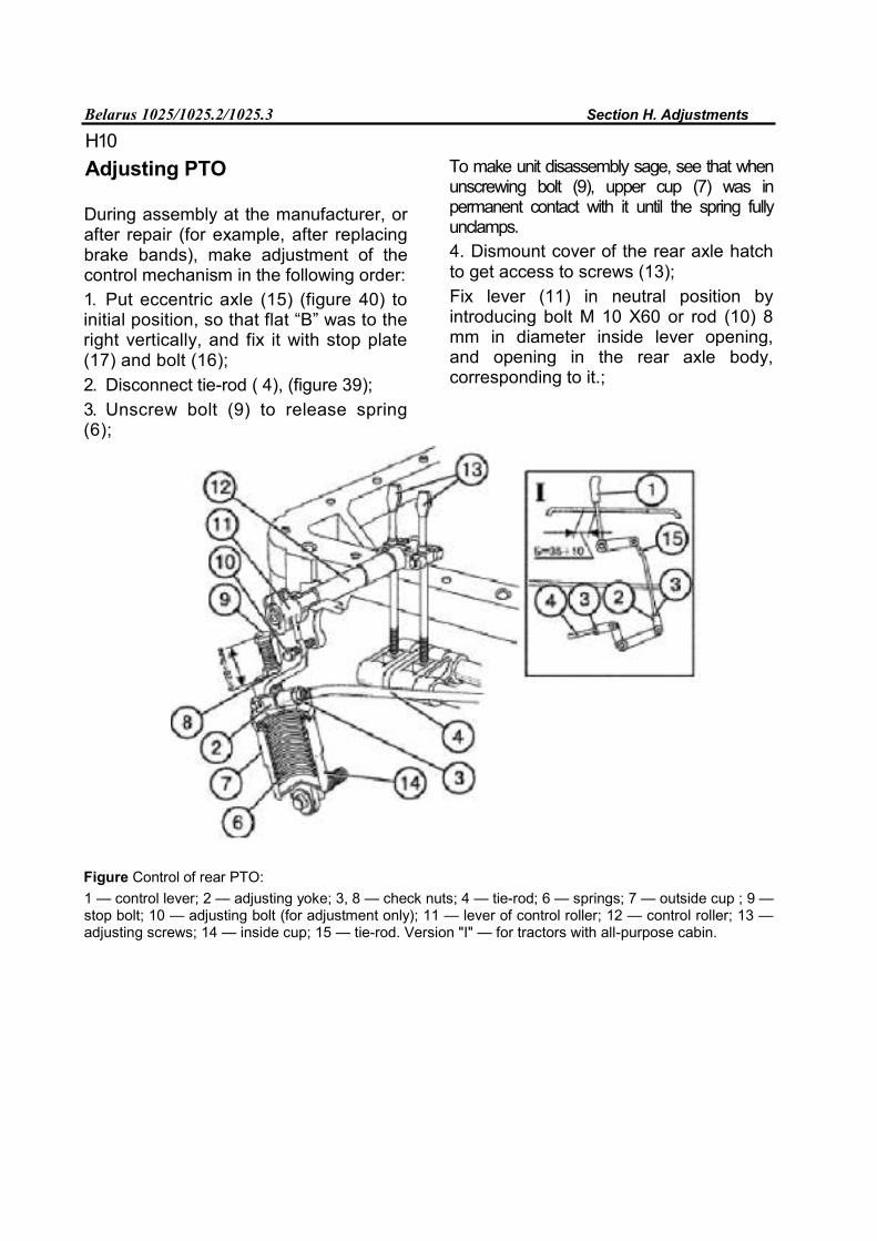
Belarus 1025/1025.2/1025.3 Section H. Adjustments
H10
Adjusting PTO
During assembly at the manufacturer, or after repair (for example, after replacing brake bands), make adjustment of the control mechanism in the following order: 1. Put eccentric axle (15) (figure 40) to initial position, so that flat “B” was to the right vertically, and fix it with stop plate (17) and bolt (16); 2. Disconnect tie-rod ( 4), (figure 39); 3. Unscrew bolt (9) to release spring (6);
To make unit disassembly sage, see that when unscrewing bolt (9), upper cup (7) was in permanent contact with it until the spring fully unclamps. 4. Dismount cover of the rear axle hatch to get access to screws (13); Fix lever (11) in neutral position by introducing bolt M 10 Х60 or rod (10) 8 mm in diameter inside lever opening, and opening in the rear axle body, corresponding to it.;
Figure Control of rear PTO: 1 — control lever; 2 — adjusting yoke; 3, 8 — check nuts; 4 — tie-rod; 6 — springs; 7 — outside cup ; 9 — stop bolt; 10 — adjusting bolt (for adjustment only); 11 — lever of control roller; 12 — control roller; 13 — adjusting screws; 14 — inside cup; 15 — tie-rod. Version "I" — for tractors with all-purpose cabin.
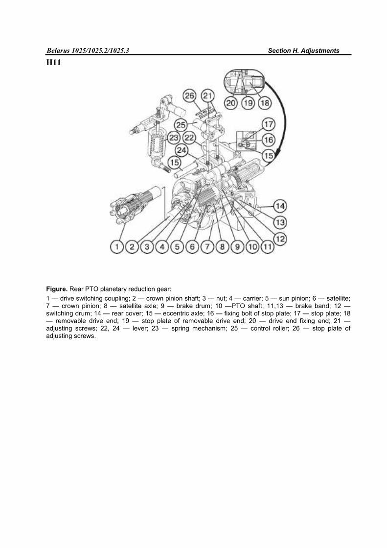
Belarus 1025/1025.2/1025.3 Section H. Adjustments
H11
Figure. Rear PTO planetary reduction gear: 1 — drive switching coupling; 2 — crown pinion shaft; 3 — nut; 4 — carrier; 5 — sun pinion; 6 — satellite; 7 — crown pinion; 8 — satellite axle; 9 — brake drum; 10 —PTO shaft; 11,13 — brake band; 12 — switching drum; 14 — rear cover; 15 — eccentric axle; 16 — fixing bolt of stop plate; 17 — stop plate; 18 — removable drive end; 19 — stop plate of removable drive end; 20 — drive end fixing end; 21 — adjusting screws; 22, 24 — lever; 23 — spring mechanism; 25 — control roller; 26 — stop plate of adjusting screws.
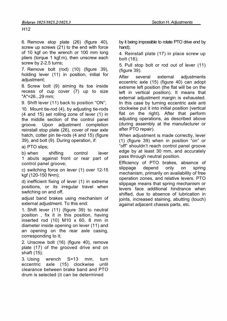
Belarus 1025/1025.2/1025.3 Section H. Adjustments
H12
6. Remove stop plate (26) (figure 40), screw up screws (21) to the end with force of 10 kgf on the wrench or 100 mm long pliers (torque 1 kgf.m), then unscrew each screw by 2-2.5 turns; 7. Remove bolt (rod) (10) (figure 39), holding lever (11) in position, initial for adjustment; 8. Screw bolt (9) aiming its toe inside recess of cup cover (7) up to size "А"=26...29 mm; 9. Shift lever (11) back to position “ON”; 10. Mount tie-rod (4), by adjusting tie-rods (4 and 15) set rolling zone of lever (1) in the middle section of the control panel groove. Upon adjustment completion reinstall stop plate (26), cover of rear axle hatch, cotter pin tie-rods (4 and 15) (figure 39), and bolt (9). During operation, if: а) PTO slips; b) when shifting control lever 1 abuts against front or rear part of control panel groove; c) switching force on lever (1) over 12-15 kgf (120-150 N•m); d) inefficient fixing of lever (1) in extreme positions, or its irregular travel when switching on and off, adjust band brakes using mechanism of external adjustment. To this end: 1. Shift lever (11) (figure 39) to neutral position , fix it in this position, having inserted rod (10) M10 x 60, 8 mm in diameter inside opening on lever (11) and an opening on the rear axle casing, corresponding to it; 2. Unscrew bolt (16) (figure 40), remove plate (17) of the grooved drive end on shaft (15); 3. Using wrench S=13 mm, turn eccentric axle (15) clockwise until clearance between brake band and PTO drum is selected (it can be determined
by it being impossible to rotate PTO drive end by hand); 4. Reinstall plate (17) in place screw up bolt (16); 5. Pull stop bolt or rod out of lever (11) (figure 39). After several external adjustments eccentric axle (15) (figure 40) can adopt extreme left position (the flat will be on the left in vertical position). It means that external adjustment margin is exhausted. In this case by turning eccentric axle anti clockwise put it into initial position (vertical flat on the right). After that perform adjusting operations, as described above (during assembly at the manufacturer or after PTO repair). When adjustment is made correctly, lever (1) (figure 39) when in position “on” or “off” shouldn’t reach control panel groove edge by at least 30 mm, and accurately pass through neutral position. Efficiency of PTO brakes, absence of slippage depend only on spring mechanism, primarily on availability of free operation zones, and relative levers. PTO slippage means that spring mechanism or levers face additional hindrance when shifted, due to absence of lubrication in joints, increased staining, abutting (touch) against adjacent chassis parts, etc.
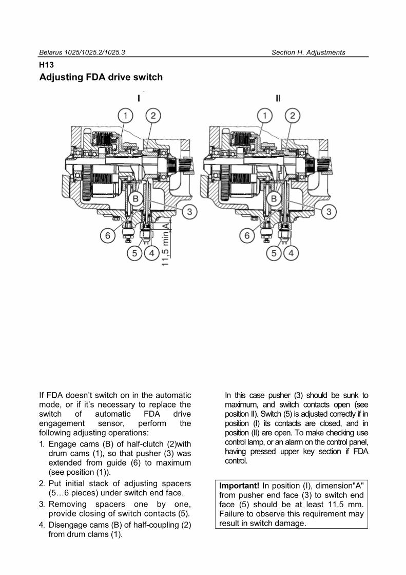
Belarus 1025/1025.2/1025.3 Section H. Adjustments
H13
Adjusting FDA drive switch
I
If FDA doesn’t switch on in the automatic mode, or if it’s necessary to replace the switch of automatic FDA drive engagement sensor, perform the following adjusting operations: 1. Engage cams (В) of half-clutch (2)with
drum cams (1), so that pusher (3) was extended from guide (6) to maximum (see position (1)).
2. Put initial stack of adjusting spacers (5…6 pieces) under switch end face.
3. Removing spacers one by one, provide closing of switch contacts (5).
4. Disengage cams (В) of half-coupling (2) from drum clams (1).
In this case pusher (3) should be sunk to maximum, and switch contacts open (see position II). Switch (5) is adjusted correctly if in position (I) its contacts are closed, and in position (II) are open. To make checking use control lamp, or an alarm on the control panel, having pressed upper key section if FDA control.
Important! In position (I), dimension"А" from pusher end face (3) to switch end face (5) should be at least 11.5 mm. Failure to observe this requirement may result in switch damage.
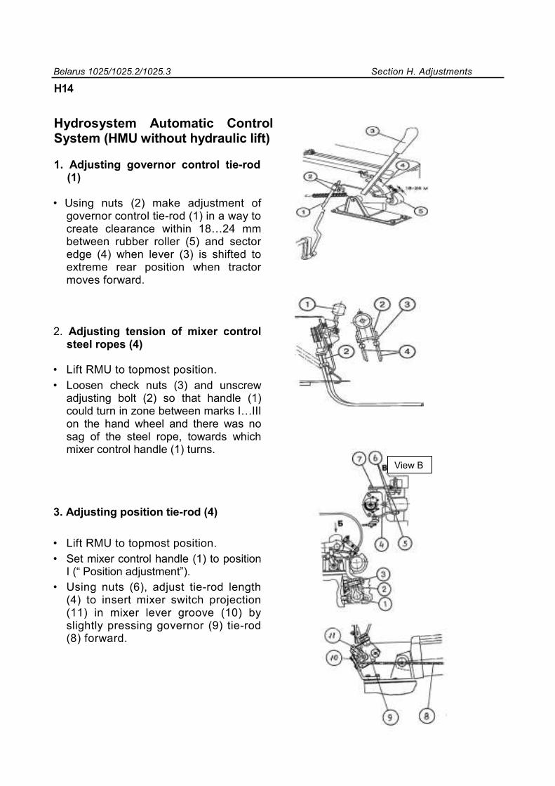
Belarus 1025/1025.2/1025.3 Section H. Adjustments
H14
Hydrosystem Automatic Control System (HMU without hydraulic lift)
1. Adjusting governor control tie-rod (1)
• Using nuts (2) make adjustment of governor control tie-rod (1) in a way to create clearance within 18…24 mm between rubber roller (5) and sector edge (4) when lever (3) is shifted to extreme rear position when tractor moves forward.
2. Adjusting tension of mixer control steel ropes (4)
• Lift RMU to topmost position. • Loosen check nuts (3) and unscrew
adjusting bolt (2) so that handle (1) could turn in zone between marks I…III on the hand wheel and there was no sag of the steel rope, towards which mixer control handle (1) turns.
3. Adjusting position tie-rod (4)
• Lift RMU to topmost position. • Set mixer control handle (1) to position
I (“ Position adjustment”). • Using nuts (6), adjust tie-rod length
(4) to insert mixer switch projection (11) in mixer lever groove (10) by slightly pressing governor (9) tie-rod (8) forward.
View B
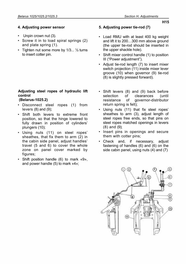
Belarus 1025/1025.2/1025.3 Section H. Adjustments
H15 4. Adjusting power sensor
• Unpin crown nut (3). • Screw it in to load spiral springs (2)
and plate spring (1). • Tighten nut some more by 1/3... ½ turns
to insert cotter pin.
5. Adjusting power tie-rod (7)
• Load RMU with at least 400 kg weight and lift it to 200…300 mm above ground (the upper tie-rod should be inserted in the upper shackle hole).
• Shift mixer control handle (1) to position III (“Power adjustment”).
• Adjust tie-rod length (7) to insert mixer switch projection (11) inside mixer lever groove (10) when governor (9) tie-rod (8) is slightly pressed forward).
Adjusting steel ropes of hydraulic lift control (Belarus-1025.2)
• Disconnect steel ropes (1) from levers (8) and (9);
• Shift both levers to extreme front position, so that the hinge lowered to fully drawn in position of cylinders’ plungers (10);
• Using nuts (11) on steel ropes’ sheathes, that fix them to arm (2) in the cabin side panel, adjust handles’ travel (5 and 6) to cover the whole zone on panel cover marked by figures;
• Shift position handle (6) to mark «9», and power handle (5) to mark «4»;
• Shift levers (8) and (9) back before selection of clearances (until resistance of governor-distributor return spring is felt);
• Using nuts (11) that fix steel ropes’ sheathes to arm (3), adjust length of steel ropes free ends, so that pins on steel ropes matched openings in levers (8) and (9);
• Insert pins in openings and secure them with cotter pins;
• Check and, if necessary, adjust fastening of handles (6) and (6) on the side cabin panel, using nuts (4) and (7)
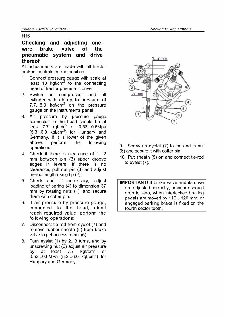
Belarus 1025/1025.2/1025.3 Section H. Adjustments
H16
Checking and adjusting one-wire brake valve of the pneumatic system and drive thereof All adjustments are made with all tractor brakes’ controls in free position. 1. Connect pressure gauge with scale at
least 10 kgf/cm2 to the connecting head of tractor pneumatic drive.
2. Switch on compressor and fill cylinder with air up to pressure of 7.7...8.0 kgf/cm2 on the pressure gauge on the instruments panel.
3. Air pressure by pressure gauge connected to the head should be at least 7.7 kgf/cm2 or 0.53...0.6Mpa (5.3...6.0 kgf/cm2) for Hungary and Germany. If it is lower of the given above, perform the following operations:
4. Check if there is clearance of 1…2 mm between pin (3) upper groove edges in levers. If there is no clearance, pull out pin (3) and adjust tie-rod length using tip (2).
5. Check and, if necessary, adjust loading of spring (4) to dimension 37 mm by rotating nuts (1), and secure them with cotter pin.
6. If air pressure by pressure gauge, connected to the head, didn’t reach required value, perform the following operations:
7. Disconnect tie-rod from eyelet (7) and remove rubber sheath (5) from brake valve to get access to nut (6).
8. Turn eyelet (1) by 2...3 turns, and by unscrewing nut (6) adjust air pressure by at least 7.7 kgf/cm2 or 0.53...0.6MPa (5.3...6.0 kgf/cm2) for Hungary and Germany.
9. Screw up eyelet (7) to the end in nut (6) and secure it with cotter pin. 10. Put sheath (5) on and connect tie-rod
to eyelet (7).
IMPORTANT! If brake valve and its drive are adjusted correctly, pressure should drop to zero, when interlocked braking pedals are moved by 110…120 mm, or engaged parking brake is fixed on the fourth sector tooth.
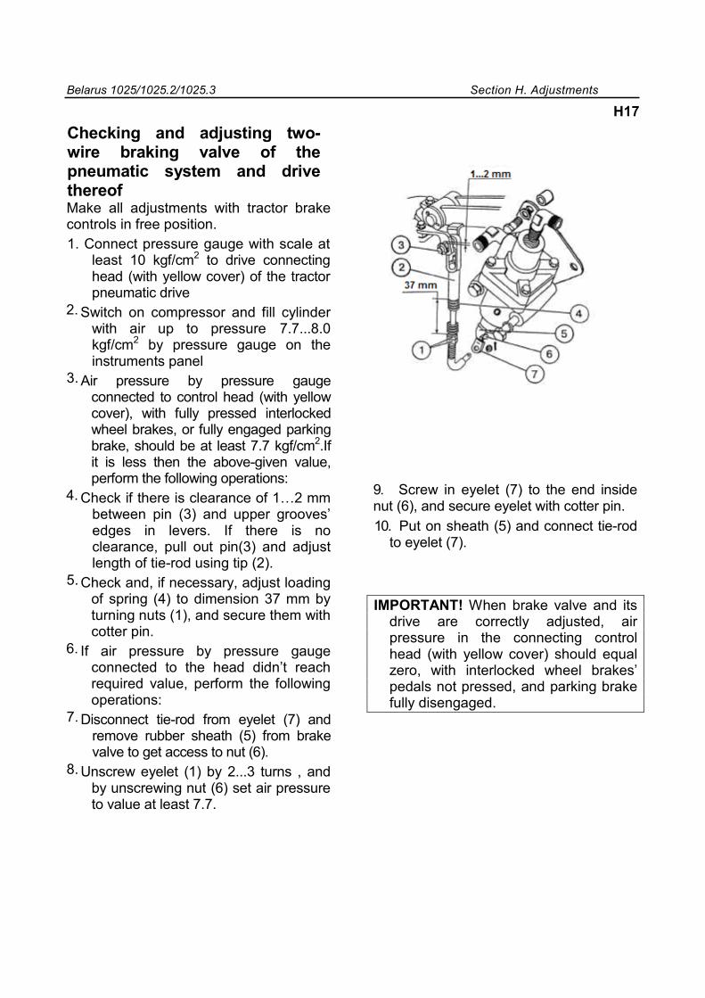
Belarus 1025/1025.2/1025.3 Section H. Adjustments
H17
Checking and adjusting two-wire braking valve of the pneumatic system and drive thereof Make all adjustments with tractor brake controls in free position. 1. Connect pressure gauge with scale at
least 10 kgf/cm2 to drive connecting head (with yellow cover) of the tractor pneumatic drive
Switch on compressor and fill cylinder with air up to pressure 7.7...8.0 kgf/cm2 by pressure gauge on the instruments panel
Air pressure by pressure gauge connected to control head (with yellow cover), with fully pressed interlocked wheel brakes, or fully engaged parking brake, should be at least 7.7 kgf/cm2.If it is less then the above-given value, perform the following operations:
Check if there is clearance of 1…2 mm between pin (3) and upper grooves’ edges in levers. If there is no clearance, pull out pin(3) and adjust length of tie-rod using tip (2).
Check and, if necessary, adjust loading of spring (4) to dimension 37 mm by turning nuts (1), and secure them with cotter pin.
If air pressure by pressure gauge connected to the head didn’t reach required value, perform the following operations:
Disconnect tie-rod from eyelet (7) and remove rubber sheath (5) from brake valve to get access to nut (6).
Unscrew eyelet (1) by 2...3 turns , and by unscrewing nut (6) set air pressure to value at least 7.7.
9. Screw in eyelet (7) to the end inside nut (6), and secure eyelet with cotter pin. 10. Put on sheath (5) and connect tie-rod
to eyelet (7).
IMPORTANT! When brake valve and its drive are correctly adjusted, air pressure in the connecting control head (with yellow cover) should equal zero, with interlocked wheel brakes’ pedals not pressed, and parking brake fully disengaged.
2.
3.
4.
5.
6.
7.
8.
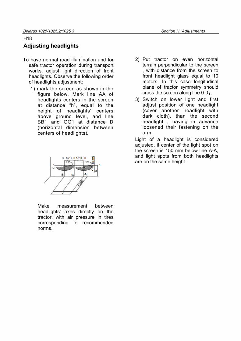
Belarus 1025/1025.2/1025.3 Section H. Adjustments
H18
Adjusting headlights
To have normal road illumination and for safe tractor operation during transport works, adjust light direction of front headlights. Observe the following order of headlights adjustment: 1) mark the screen as shown in the
figure below. Mark line AA of headlights centers in the screen at distance “h”, equal to the height of headlights’ centers above ground level, and line BB1 and GG1 at distance D (horizontal dimension between centers of headlights).
2) Put tractor on even horizontal terrain perpendicular to the screen , with distance from the screen to front headlight glass equal to 10 meters. In this case longitudinal plane of tractor symmetry should cross the screen along line 0-01;
3) Switch on lower light and first adjust position of one headlight (cover another headlight with dark cloth), than the second headlight , having in advance loosened their fastening on the arm.
Light of a headlight is considered adjusted, if center of the light spot on the screen is 150 mm below line A-A, and light spots from both headlights are on the same height.
Make measurement between headlights’ axes directly on the tractor, with air pressure in tires corresponding to recommended norms.
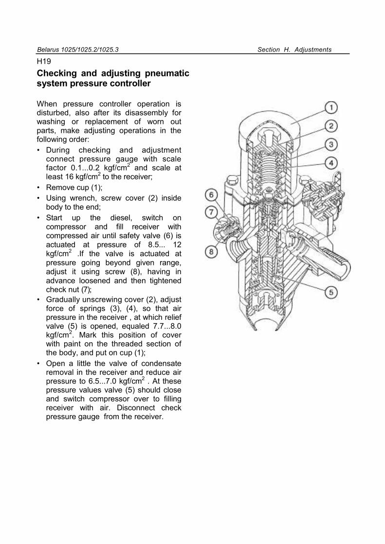
Belarus 1025/1025.2/1025.3 Section H. Adjustments
H19
Checking and adjusting pneumatic system pressure controller
When pressure controller operation is disturbed, also after its disassembly for washing or replacement of worn out parts, make adjusting operations in the following order: • During checking and adjustment
connect pressure gauge with scale factor 0.1...0.2 kgf/cm2 and scale at least 16 kgf/cm2 to the receiver;
• Remove cup (1); • Using wrench, screw cover (2) inside
body to the end; • Start up the diesel, switch on
compressor and fill receiver with compressed air until safety valve (6) is actuated at pressure of 8.5... 12 kgf/cm2 .If the valve is actuated at pressure going beyond given range, adjust it using screw (8), having in advance loosened and then tightened check nut (7);
• Gradually unscrewing cover (2), adjust force of springs (3), (4), so that air pressure in the receiver , at which relief valve (5) is opened, equaled 7.7...8.0 kgf/cm2. Mark this position of cover with paint on the threaded section of the body, and put on cup (1);
• Open a little the valve of condensate removal in the receiver and reduce air pressure to 6.5...7.0 kgf/cm2 . At these pressure values valve (5) should close and switch compressor over to filling receiver with air. Disconnect check pressure gauge from the receiver.
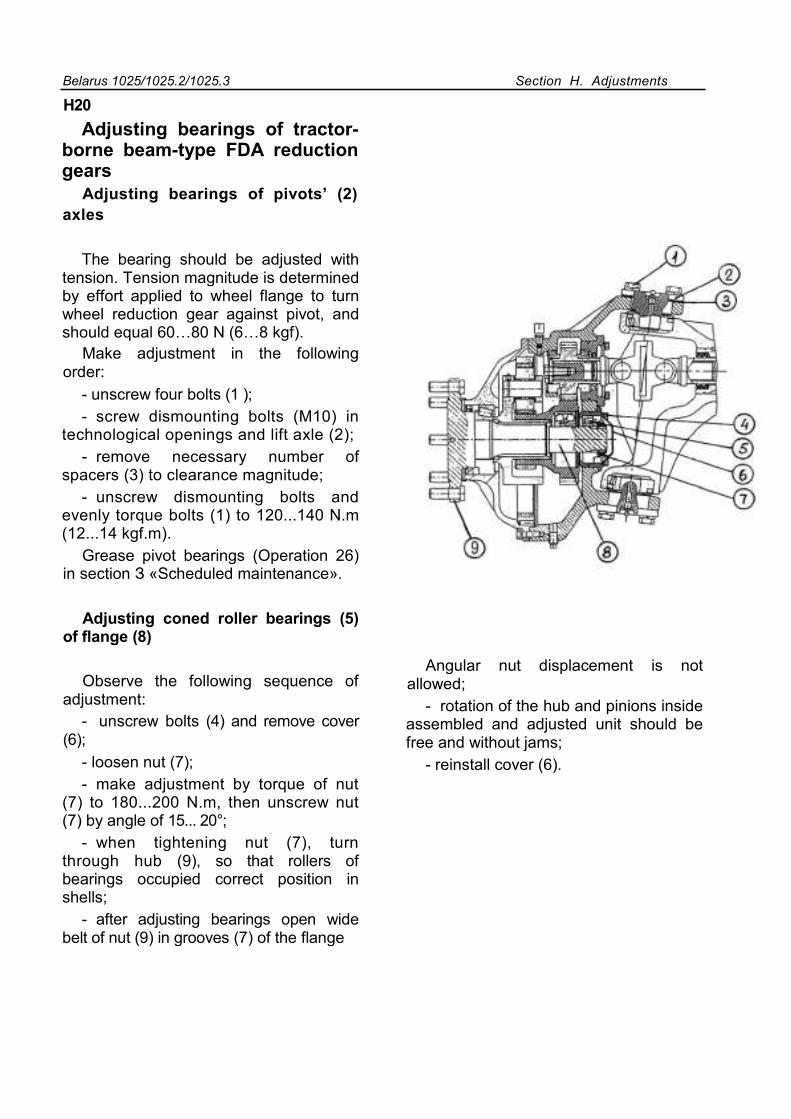
Belarus 1025/1025.2/1025.3 Section H. Adjustments
H20
Adjusting bearings of tractor-borne beam-type FDA reduction gears
Adjusting bearings of pivots’ (2) axles
The bearing should be adjusted with tension. Tension magnitude is determined by effort applied to wheel flange to turn wheel reduction gear against pivot, and should equal 60…80 N (6…8 kgf).
Make adjustment in the following order:
- unscrew four bolts (1 ); - screw dismounting bolts (M10) in
technological openings and lift axle (2); - remove necessary number of
spacers (3) to clearance magnitude; - unscrew dismounting bolts and
evenly torque bolts (1) to 120...140 N.m (12...14 kgf.m).
Grease pivot bearings (Operation 26) in section З «Scheduled maintenance».
Adjusting coned roller bearings (5) of flange (8)
Observe the following sequence of adjustment:
- unscrew bolts (4) and remove cover (6);
- loosen nut (7); - make adjustment by torque of nut
(7) to 180...200 N.m, then unscrew nut (7) by angle of 15... 20°;
- when tightening nut (7), turn through hub (9), so that rollers of bearings occupied correct position in shells;
- after adjusting bearings open wide belt of nut (9) in grooves (7) of the flange
Angular nut displacement is not allowed;
- rotation of the hub and pinions inside assembled and adjusted unit should be free and without jams;
- reinstall cover (6).
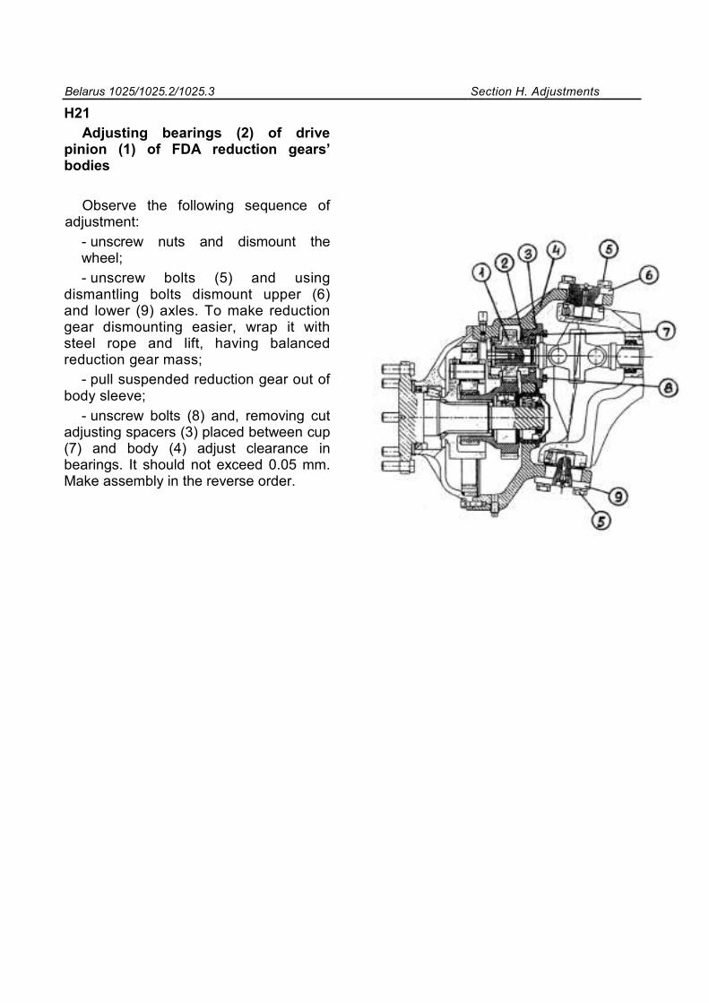
Belarus 1025/1025.2/1025.3 Section H. Adjustments
H21 Adjusting bearings (2) of drive
pinion (1) of FDA reduction gears’ bodies
Observe the following sequence of adjustment:
- unscrew nuts and dismount the wheel; - unscrew bolts (5) and using
dismantling bolts dismount upper (6) and lower (9) axles. To make reduction gear dismounting easier, wrap it with steel rope and lift, having balanced reduction gear mass;
- pull suspended reduction gear out of body sleeve;
- unscrew bolts (8) and, removing cut adjusting spacers (3) placed between cup (7) and body (4) adjust clearance in bearings. It should not exceed 0.05 mm. Make assembly in the reverse order.
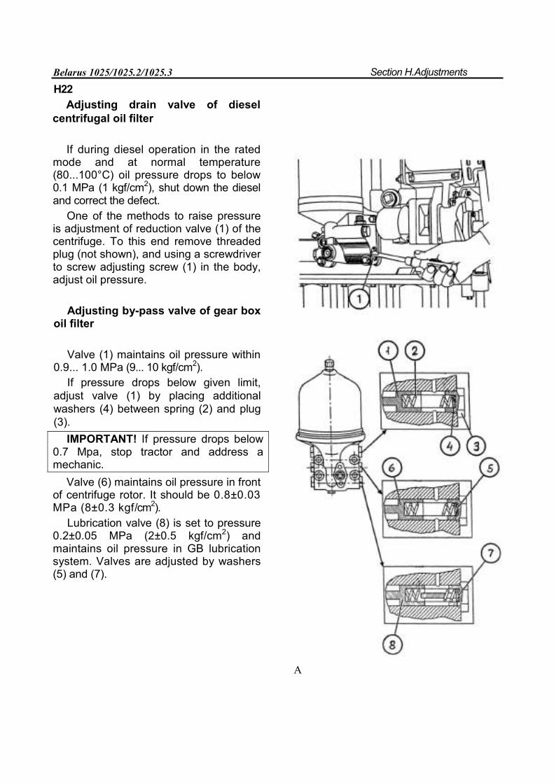
Belarus 1025/1025.2/1025.3 Section H.Adjustments
H22 Adjusting drain valve of diesel
centrifugal oil filter
If during diesel operation in the rated mode and at normal temperature (80...100°С) oil pressure drops to below 0.1 MPa (1 kgf/cm2), shut down the diesel and correct the defect.
One of the methods to raise pressure is adjustment of reduction valve (1) of the centrifuge. To this end remove threaded plug (not shown), and using a screwdriver to screw adjusting screw (1) in the body, adjust oil pressure.
Adjusting by-pass valve of gear box oil filter
Valve (1) maintains oil pressure within 0.9... 1.0 MPa (9... 10 kgf/cm2).
If pressure drops below given limit, adjust valve (1) by placing additional washers (4) between spring (2) and plug (3).
IMPORTANT! If pressure drops below 0.7 Mpa, stop tractor and address a mechanic.
Valve (6) maintains oil pressure in front of centrifuge rotor. It should be 0.8±0.03 MPa (8±0.3 kgf/cm2).
Lubrication valve (8) is set to pressure 0.2±0.05 MPa (2±0.5 kgf/cm2) and maintains oil pressure in GB lubrication system. Valves are adjusted by washers (5) and (7).
A
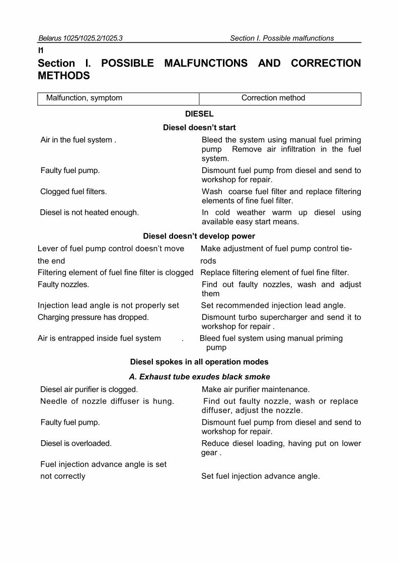
Belarus 1025/1025.2/1025.3 Section I. Possible malfunctions
I1
Section I. POSSIBLE MALFUNCTIONS AND CORRECTION METHODS
Malfunction, symptom Correction method
DIESEL Diesel doesn’t start
Air in the fuel system . Bleed the system using manual fuel priming pump Remove air infiltration in the fuel system.
Faulty fuel pump. Dismount fuel pump from diesel and send to workshop for repair.
Clogged fuel filters. Wash coarse fuel filter and replace filtering elements of fine fuel filter. Diesel is not heated enough. In cold weather warm up diesel using
available easy start means.
Diesel doesn’t develop power
Lever of fuel pump control doesn’t move Make adjustment of fuel pump control tie- the end rods
Filtering element of fuel fine filter is clogged Replace filtering element of fuel fine filter. Faulty nozzles. Find out faulty nozzles, wash and adjust
them Injection lead angle is not properly set Set recommended injection lead angle. Charging pressure has dropped. Dismount turbo supercharger and send it to
workshop for repair . Air is entrapped inside fuel system . Bleed fuel system using manual priming pump
Diesel spokes in all operation modes
А. Exhaust tube exudes black smoke
Diesel air purifier is clogged. Make air purifier maintenance. Needle of nozzle diffuser is hung. Find out faulty nozzle, wash or replace
diffuser, adjust the nozzle. Faulty fuel pump. Dismount fuel pump from diesel and send to
workshop for repair. Diesel is overloaded. Reduce diesel loading, having put on lower
gear . Fuel injection advance angle is set not correctly Set fuel injection advance angle.
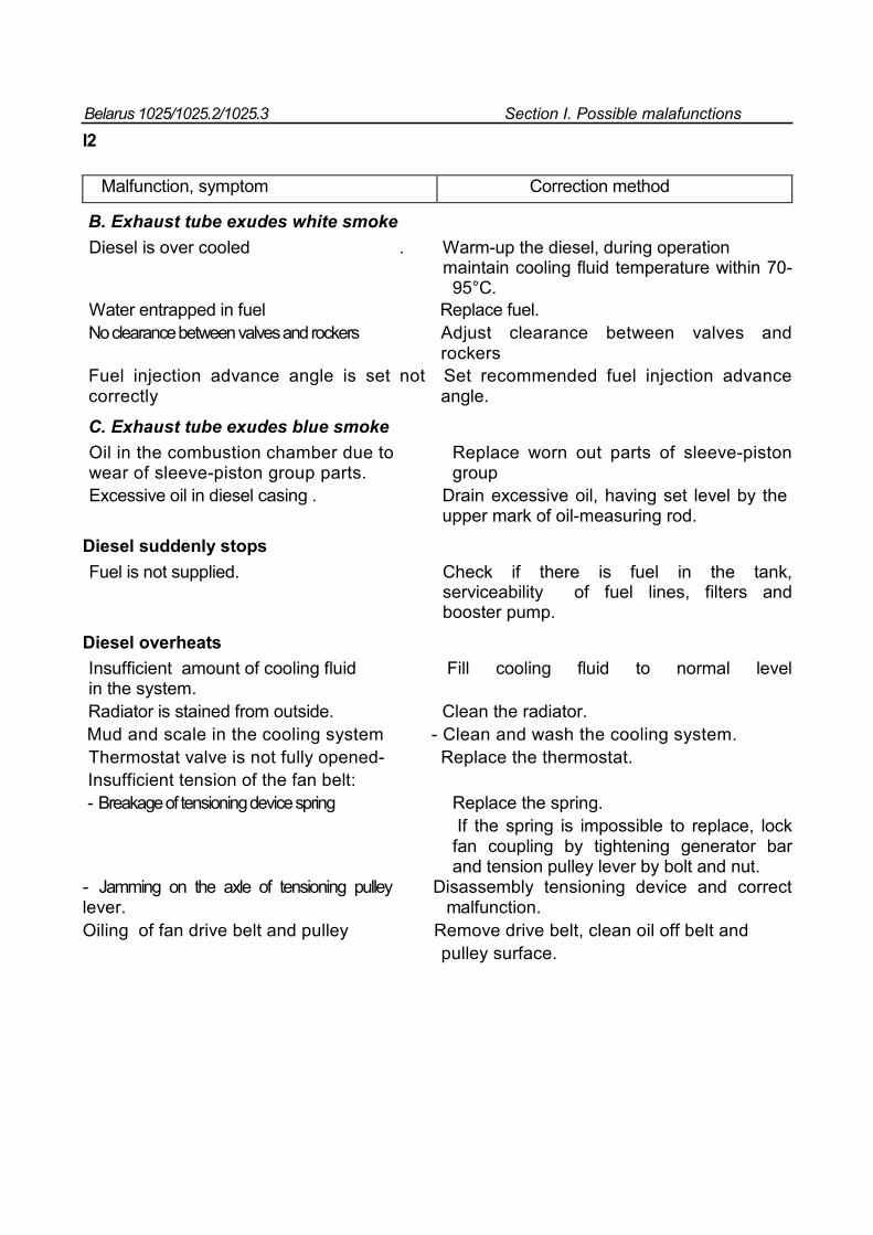
Belarus 1025/1025.2/1025.3 Section I. Possible malafunctions
I2
Malfunction, symptom Correction method
B. Exhaust tube exudes white smoke Diesel is over cooled . Warm-up the diesel, during operation maintain cooling fluid temperature within 70- 95°С. Water entrapped in fuel Replace fuel. No clearance between valves and rockers Adjust clearance between valves and rockers Fuel injection advance angle is set not Set recommended fuel injection advance correctly angle.
C. Exhaust tube exudes blue smoke
Oil in the combustion chamber due to Replace worn out parts of sleeve-piston wear of sleeve-piston group parts. group Excessive oil in diesel casing . Drain excessive oil, having set level by the upper mark of oil-measuring rod.
Diesel suddenly stops
Fuel is not supplied. Check if there is fuel in the tank, serviceability of fuel lines, filters and booster pump.
Diesel overheats Insufficient amount of cooling fluid Fill cooling fluid to normal level in the system. Radiator is stained from outside. Clean the radiator. Mud and scale in the cooling system - Clean and wash the cooling system. Thermostat valve is not fully opened- Replace the thermostat. Insufficient tension of the fan belt:
- Breakage of tensioning device spring Replace the spring. If the spring is impossible to replace, lock fan coupling by tightening generator bar and tension pulley lever by bolt and nut.
- Jamming on the axle of tensioning pulley Disassembly tensioning device and correct lever. malfunction. Oiling of fan drive belt and pulley Remove drive belt, clean oil off belt and pulley surface.
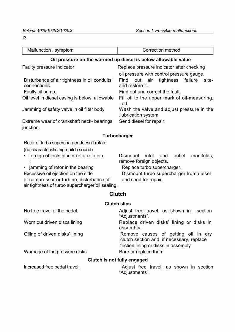
Belarus 1025/1025.2/1025.3 Section I. Possible malfunctions
I3
Malfunction , symptom Correction method
Oil pressure on the warmed up diesel is below allowable value Faulty pressure indicator Replace pressure indicator after checking oil pressure with control pressure gauge. Disturbance of air tightness in oil conduits’ Find out air tightness failure site- connections. and restore it. Faulty oil pump. Find out and correct the fault.
Oil level in diesel casing is below allowable Fill oil to the upper mark of oil-measuring, rod. Jamming of safety valve in oil filter body Wash the valve and adjust pressure in the .lubrication system. Extreme wear of crankshaft neck- bearings Send diesel for repair. junction.
Turbocharger
Rotor of turbo supercharger doesn’t rotate (no characteristic high-pitch sound): • foreign objects hinder rotor rotation Dismount inlet and outlet manifolds,
; remove foreign objects. • jamming of rotor in the bearing Replace turbo supercharger. Excessive oil ejection on the side Dismount turbo supercharger from diesel of compressor or turbine, disturbance of and send for repair. air tightness of turbo supercharger oil sealing.
Clutch Clutch slips
No free travel of the pedal. Adjust free travel, as shown in section “Adjustments”.
Worn out driven discs lining Replace driven disks’ lining or disks in assembly.
Oiling of driven disks’ lining Remove causes of getting oil in dry clutch section and, if necessary, replace
friction lining or disks in assembly Warpage of the pressure disks Bore or replace them
Clutch is not fully engaged
Increased free pedal travel. Adjust free travel, as shown in section “Adjustments”.
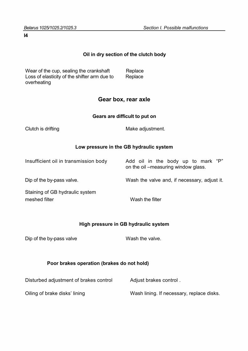
Belarus 1025/1025.2/1025.3 Section I. Possible malfunctions
I4
Oil in dry section of the clutch body
Wear of the cup, sealing the crankshaft Replace Loss of elasticity of the shifter arm due to Replace overheating
Gear box, rear axle
Gears are difficult to put on
Clutch is drifting Make adjustment.
Low pressure in the GB hydraulic system
Insufficient oil in transmission body Add oil in the body up to mark “P” on the oil –measuring window glass.
Dip of the by-pass valve. Wash the valve and, if necessary, adjust it.
Staining of GB hydraulic system meshed filter Wash the filter
High pressure in GB hydraulic system
Dip of the by-pass valve Wash the valve.
Poor brakes operation (brakes do not hold)
Disturbed adjustment of brakes control Adjust brakes control .
Oiling of brake disks’ lining Wash lining. If necessary, replace disks.
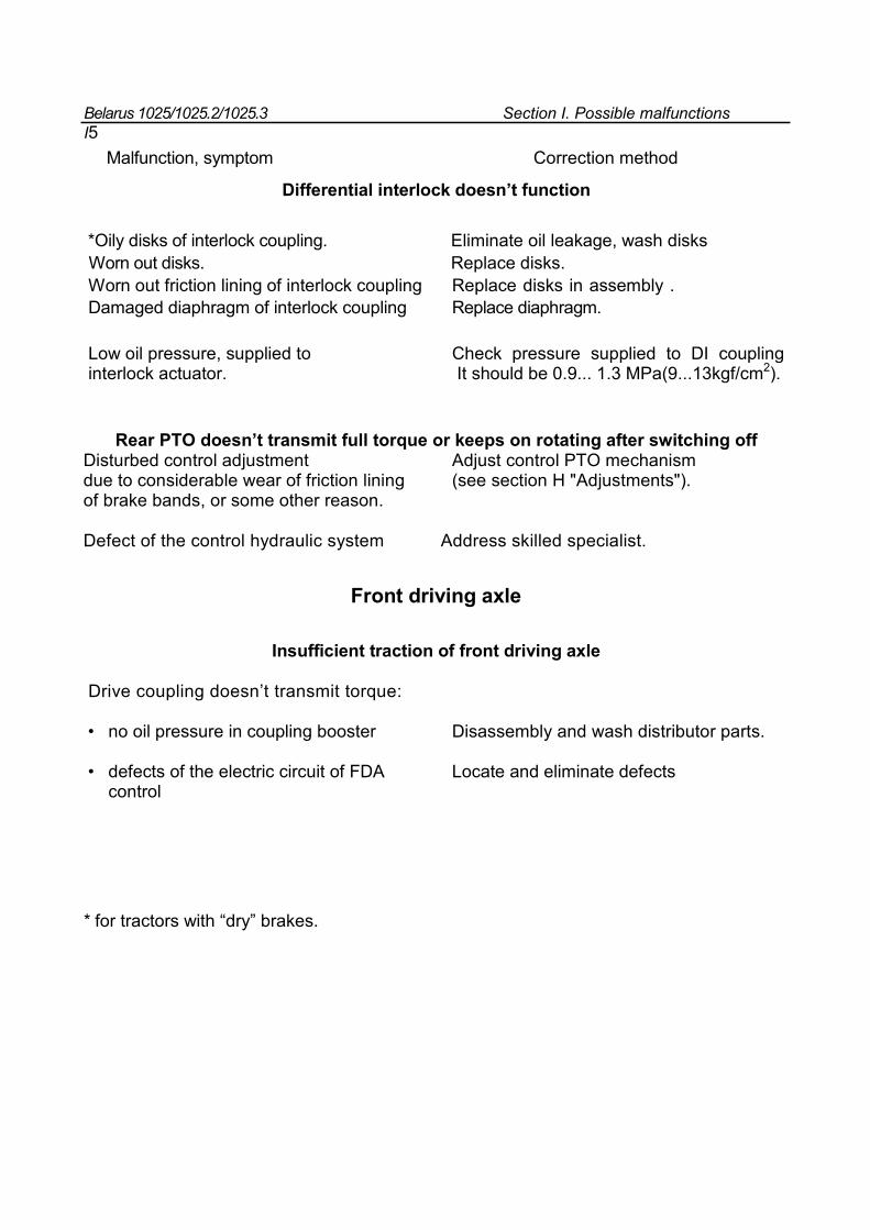
Belarus 1025/1025.2/1025.3 Section I. Possible malfunctions I5
Malfunction, symptom Correction method
Differential interlock doesn’t function
*Oily disks of interlock coupling. Eliminate oil leakage, wash disks Worn out disks. Replace disks. Worn out friction lining of interlock coupling Replace disks in assembly . Damaged diaphragm of interlock coupling Replace diaphragm.
Low oil pressure, supplied to Check pressure supplied to DI coupling interlock actuator. It should be 0.9... 1.3 MPa(9...13kgf/cm2).
Rear PTO doesn’t transmit full torque or keeps on rotating after switching off Disturbed control adjustment Adjust control PTO mechanism due to considerable wear of friction lining (see section H "Adjustments"). of brake bands, or some other reason. Defect of the control hydraulic system Address skilled specialist.
Front driving axle
Insufficient traction of front driving axle Drive coupling doesn’t transmit torque: • no oil pressure in coupling booster Disassembly and wash distributor parts. • defects of the electric circuit of FDA Locate and eliminate defects
control * for tractors with “dry” brakes.
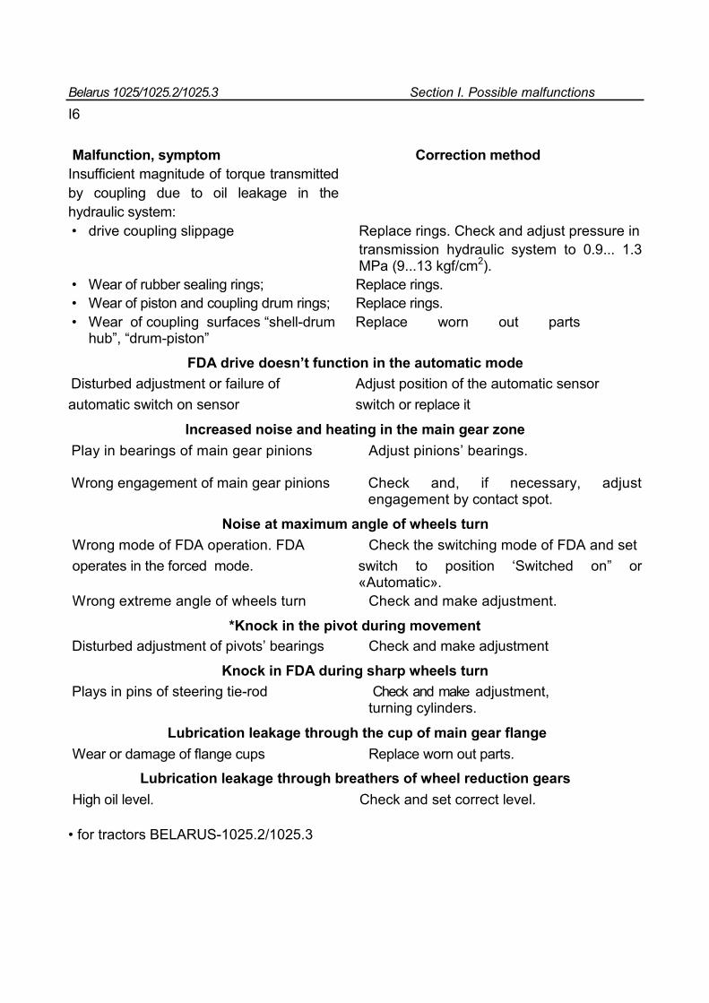
Belarus 1025/1025.2/1025.3 Section I. Possible malfunctions
I6
Malfunction, symptom Correction method Insufficient magnitude of torque transmitted by coupling due to oil leakage in the hydraulic system: • drive coupling slippage Replace rings. Check and adjust pressure in transmission hydraulic system to 0.9... 1.3 MPa (9...13 kgf/cm2). • Wear of rubber sealing rings; Replace rings. • Wear of piston and coupling drum rings; Replace rings. • Wear of coupling surfaces “shell-drum Replace worn out parts
hub”, “drum-piston”
FDA drive doesn’t function in the automatic mode
Disturbed adjustment or failure of Adjust position of the automatic sensor automatic switch on sensor switch or replace it
Increased noise and heating in the main gear zone
Play in bearings of main gear pinions Adjust pinions’ bearings. Wrong engagement of main gear pinions Check and, if necessary, adjust
engagement by contact spot.
Noise at maximum angle of wheels turn
Wrong mode of FDA operation. FDA Check the switching mode of FDA and set operates in the forced mode. switch to position ‘Switched on” or
«Automatic». Wrong extreme angle of wheels turn Check and make adjustment.
*Knock in the pivot during movement Disturbed adjustment of pivots’ bearings Check and make adjustment
Knock in FDA during sharp wheels turn
Plays in pins of steering tie-rod Check and make adjustment, turning cylinders.
Lubrication leakage through the cup of main gear flange
Wear or damage of flange cups Replace worn out parts.
Lubrication leakage through breathers of wheel reduction gears
High oil level. Check and set correct level. • for tractors BELARUS-1025.2/1025.3
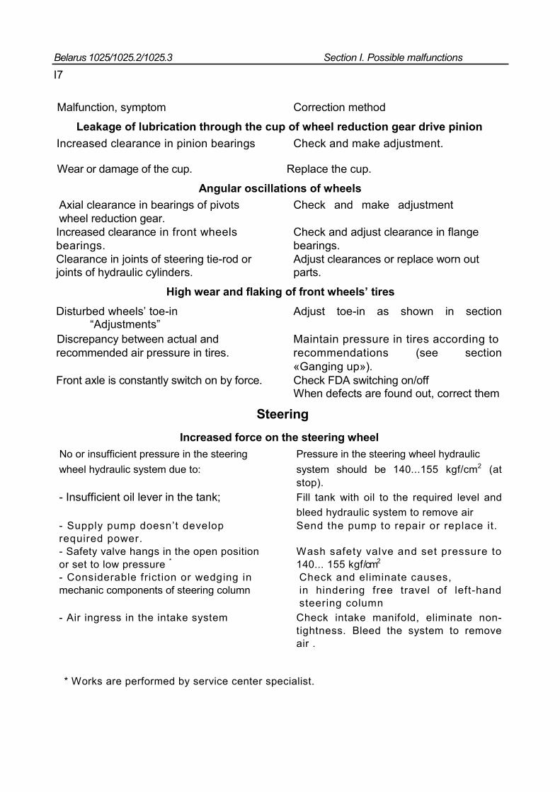
Belarus 1025/1025.2/1025.3 Section I. Possible malfunctions
I7
Malfunction, symptom Correction method
Leakage of lubrication through the cup of wheel reduction gear drive pinion
Increased clearance in pinion bearings Check and make adjustment. Wear or damage of the cup. Replace the cup.
Angular oscillations of wheels
Axial clearance in bearings of pivots Check and make adjustment wheel reduction gear. Increased clearance in front wheels Check and adjust clearance in flange bearings. bearings. Clearance in joints of steering tie-rod or Adjust clearances or replace worn out joints of hydraulic cylinders. parts.
High wear and flaking of front wheels’ tires
Disturbed wheels’ toe-in Adjust toe-in as shown in section “Adjustments” Discrepancy between actual and Maintain pressure in tires according to recommended air pressure in tires. recommendations (see section
«Ganging up»). Front axle is constantly switch on by force. Check FDA switching on/off
When defects are found out, correct them
Steering Increased force on the steering wheel
No or insufficient pressure in the steering Pressure in the steering wheel hydraulic wheel hydraulic system due to: system should be 140...155 kgf/cm2 (at
stop). - Insufficient oil lever in the tank; Fill tank with oil to the required level and
bleed hydraulic system to remove air - Supply pump doesn’t develop Send the pump to repair or replace it. required power. - Safety valve hangs in the open position Wash safety valve and set pressure to or set to low pressure * 140... 155 kgf/cm2 - Considerable friction or wedging in Check and eliminate causes, mechanic components of steering column in hindering free travel of left-hand
steering column - Air ingress in the intake system Check intake manifold, eliminate non-
tightness. Bleed the system to remove air .
* Works are performed by service center specialist.
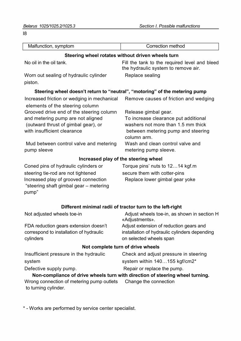
Belarus 1025/1025.2/1025.3 Section I. Possible malfunctions
I8
Malfunction, symptom Correction method
Steering wheel rotates without driven wheels turn
No oil in the oil tank. Fill the tank to the required level and bleed the hydraulic system to remove air.
Worn out sealing of hydraulic cylinder Replace sealing piston.
Steering wheel doesn’t return to “neutral”, “motoring” of the metering pump
Increased friction or wedging in mechanical Remove causes of friction and wedging elements of the steering column Grooved drive end of the steering column Release gimbal gear. and metering pump are not aligned To increase clearance put additional (outward thrust of gimbal gear), or washers not more than 1.5 mm thick with insufficient clearance between metering pump and steering column arm. Mud between control valve and metering Wash and clean control valve and pump sleeve metering pump sleeve.
Increased play of the steering wheel Coned pins of hydraulic cylinders or Torque pins’ nuts to 12…14 kgf.m steering tie-rod are not tightened secure them with cotter-pins Increased play of grooved connection Replace lower gimbal gear yoke “steering shaft gimbal gear – metering pump”
Different minimal radii of tractor turn to the left-right Not adjusted wheels toe-in Adjust wheels toe-in, as shown in section H
«Adjustments». FDA reduction gears extension doesn’t Adjust extension of reduction gears and correspond to installation of hydraulic installation of hydraulic cylinders depending cylinders on selected wheels span
Not complete turn of drive wheels
Insufficient pressure in the hydraulic Check and adjust pressure in steering system system within 140…155 kgf/cm2* Defective supply pump. Repair or replace the pump.
Non-compliance of drive wheels turn with direction of steering wheel turning. Wrong connection of metering pump outlets Change the connection to turning cylinder.
* - Works are performed by service center specialist.
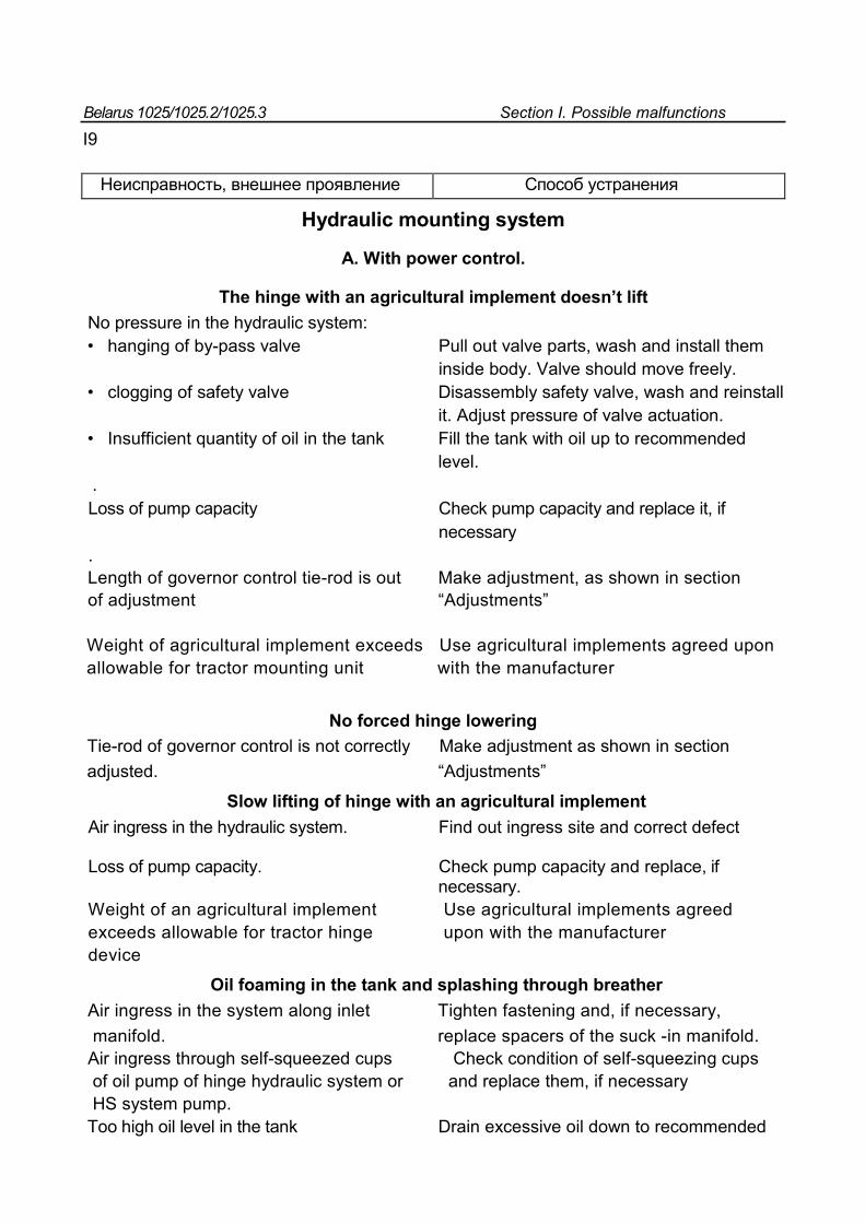
Belarus 1025/1025.2/1025.3 Section I. Possible malfunctions
I9
Неисправность, внешнее проявление Способ устранения
Hydraulic mounting system
А. With power control.
The hinge with an agricultural implement doesn’t lift No pressure in the hydraulic system: • hanging of by-pass valve Pull out valve parts, wash and install them inside body. Valve should move freely. • clogging of safety valve Disassembly safety valve, wash and reinstall it. Adjust pressure of valve actuation. • Insufficient quantity of oil in the tank Fill the tank with oil up to recommended level. . Loss of pump capacity Check pump capacity and replace it, if necessary . Length of governor control tie-rod is out Make adjustment, as shown in section of adjustment “Adjustments” Weight of agricultural implement exceeds Use agricultural implements agreed upon allowable for tractor mounting unit with the manufacturer
No forced hinge lowering
Tie-rod of governor control is not correctly Make adjustment as shown in section adjusted. “Adjustments”
Slow lifting of hinge with an agricultural implement Air ingress in the hydraulic system. Find out ingress site and correct defect
Loss of pump capacity. Check pump capacity and replace, if
necessary. Weight of an agricultural implement Use agricultural implements agreed exceeds allowable for tractor hinge upon with the manufacturer device
Oil foaming in the tank and splashing through breather
Air ingress in the system along inlet Tighten fastening and, if necessary, manifold. replace spacers of the suck -in manifold. Air ingress through self-squeezed cups Check condition of self-squeezing cups of oil pump of hinge hydraulic system or and replace them, if necessary HS system pump. Too high oil level in the tank Drain excessive oil down to recommended
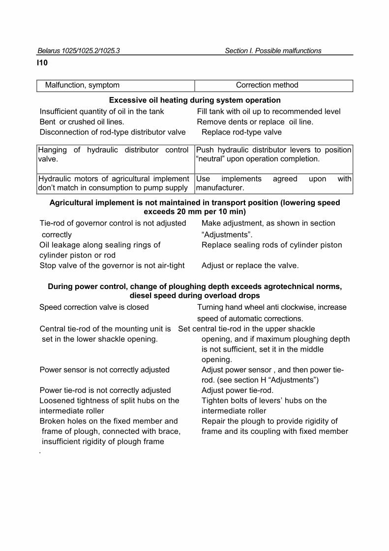
Belarus 1025/1025.2/1025.3 Section I. Possible malfunctions
I10
Malfunction, symptom Correction method
Excessive oil heating during system operation
Insufficient quantity of oil in the tank Fill tank with oil up to recommended level Bent or crushed oil lines. Remove dents or replace oil line. Disconnection of rod-type distributor valve Replace rod-type valve
Hanging of hydraulic distributor control valve.
Push hydraulic distributor levers to position “neutral” upon operation completion.
Hydraulic motors of agricultural implement don’t match in consumption to pump supply
Use implements agreed upon with manufacturer.
Agricultural implement is not maintained in transport position (lowering speed exceeds 20 mm per 10 min)
Tie-rod of governor control is not adjusted Make adjustment, as shown in section correctly “Adjustments”. Oil leakage along sealing rings of Replace sealing rods of cylinder piston cylinder piston or rod Stop valve of the governor is not air-tight Adjust or replace the valve.
During power control, change of ploughing depth exceeds agrotechnical norms, diesel speed during overload drops
Speed correction valve is closed Turning hand wheel anti clockwise, increase speed of automatic corrections. Central tie-rod of the mounting unit is Set central tie-rod in the upper shackle set in the lower shackle opening. opening, and if maximum ploughing depth is not sufficient, set it in the middle opening. Power sensor is not correctly adjusted Adjust power sensor , and then power tie- rod. (see section H “Adjustments”) Power tie-rod is not correctly adjusted Adjust power tie-rod. Loosened tightness of split hubs on the Tighten bolts of levers’ hubs on the intermediate roller intermediate roller Broken holes on the fixed member and Repair the plough to provide rigidity of frame of plough, connected with brace, frame and its coupling with fixed member insufficient rigidity of plough frame .
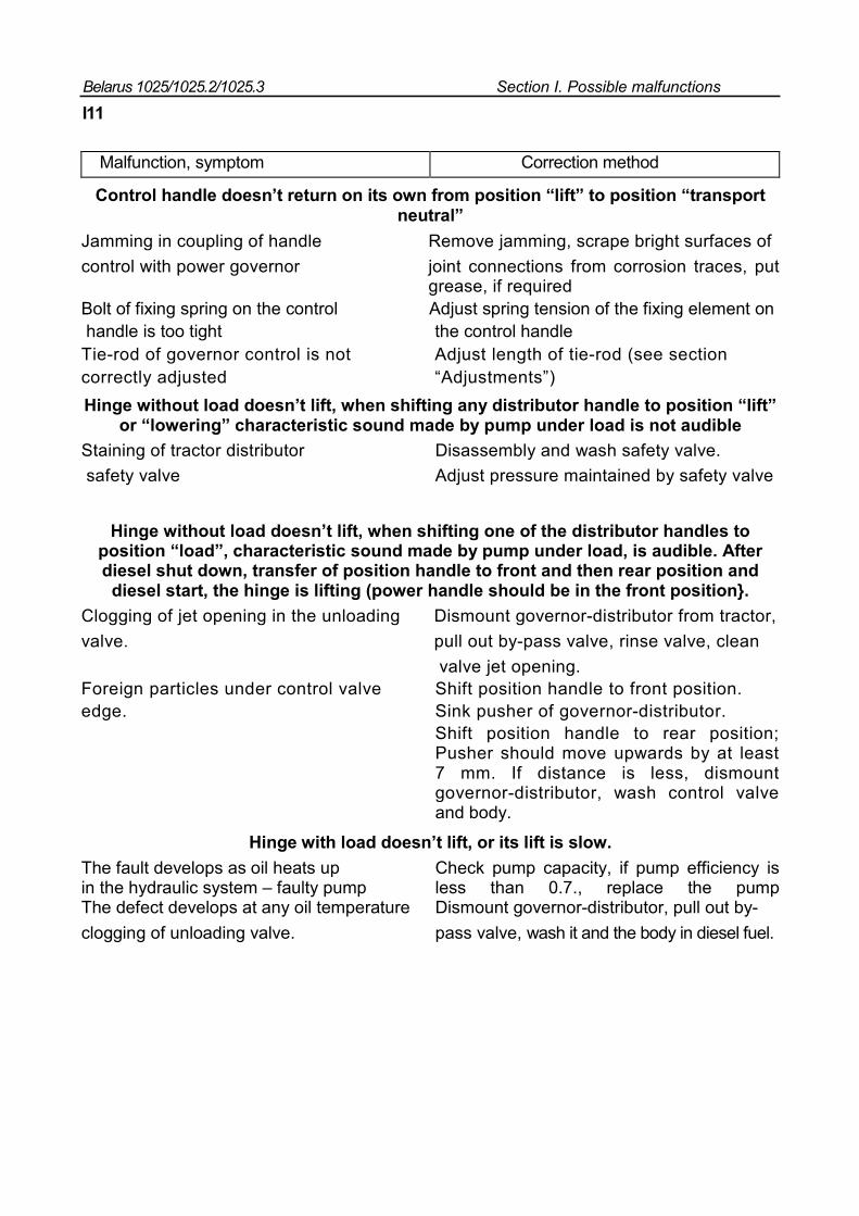
Belarus 1025/1025.2/1025.3 Section I. Possible malfunctions
I11
Malfunction, symptom Correction method
Control handle doesn’t return on its own from position “lift” to position “transport neutral”
Jamming in coupling of handle Remove jamming, scrape bright surfaces of control with power governor joint connections from corrosion traces, put grease, if required Bolt of fixing spring on the control Adjust spring tension of the fixing element on handle is too tight the control handle Tie-rod of governor control is not Adjust length of tie-rod (see section correctly adjusted “Adjustments”) Hinge without load doesn’t lift, when shifting any distributor handle to position “lift”
or “lowering” characteristic sound made by pump under load is not audible
Staining of tractor distributor Disassembly and wash safety valve. safety valve Adjust pressure maintained by safety valve
Hinge without load doesn’t lift, when shifting one of the distributor handles to position “load”, characteristic sound made by pump under load, is audible. After diesel shut down, transfer of position handle to front and then rear position and
diesel start, the hinge is lifting (power handle should be in the front position}. Clogging of jet opening in the unloading Dismount governor-distributor from tractor, valve. pull out by-pass valve, rinse valve, clean valve jet opening. Foreign particles under control valve Shift position handle to front position. edge. Sink pusher of governor-distributor.
Shift position handle to rear position; Pusher should move upwards by at least 7 mm. If distance is less, dismount governor-distributor, wash control valve and body.
Hinge with load doesn’t lift, or its lift is slow. The fault develops as oil heats up Check pump capacity, if pump efficiency is in the hydraulic system – faulty pump less than 0.7., replace the pump The defect develops at any oil temperature Dismount governor-distributor, pull out by- clogging of unloading valve. pass valve, wash it and the body in diesel fuel.
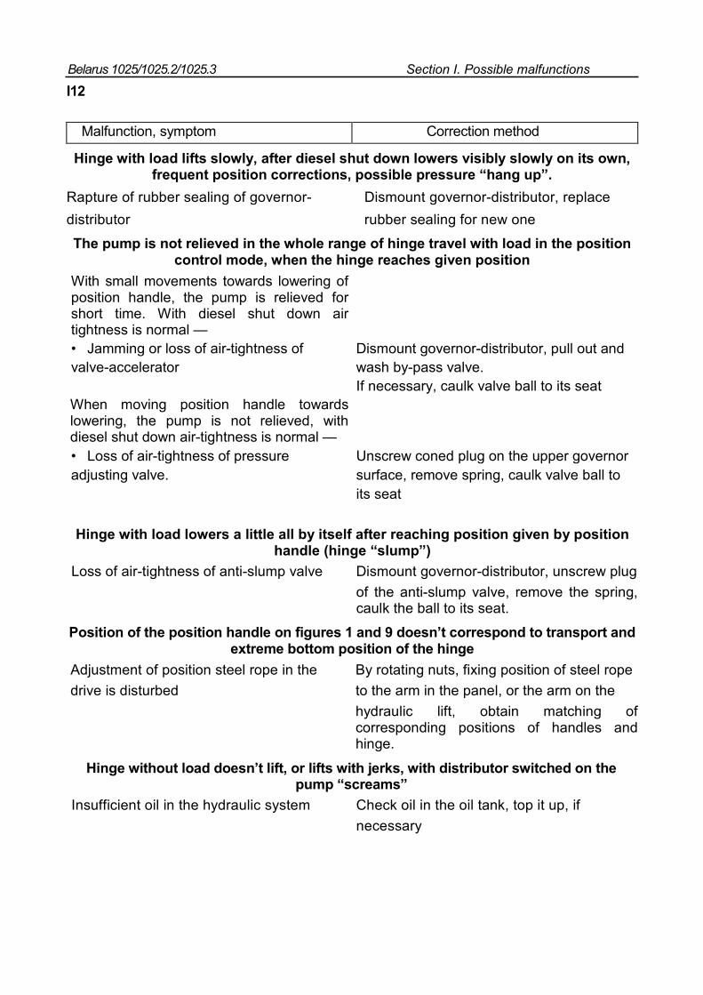
Belarus 1025/1025.2/1025.3 Section I. Possible malfunctions
I12
Malfunction, symptom Correction method
Hinge with load lifts slowly, after diesel shut down lowers visibly slowly on its own, frequent position corrections, possible pressure “hang up”.
Rapture of rubber sealing of governor- Dismount governor-distributor, replace distributor rubber sealing for new one
The pump is not relieved in the whole range of hinge travel with load in the position control mode, when the hinge reaches given position
With small movements towards lowering of position handle, the pump is relieved for short time. With diesel shut down air tightness is normal — • Jamming or loss of air-tightness of Dismount governor-distributor, pull out and valve-accelerator wash by-pass valve. If necessary, caulk valve ball to its seat When moving position handle towards lowering, the pump is not relieved, with diesel shut down air-tightness is normal — • Loss of air-tightness of pressure Unscrew coned plug on the upper governor adjusting valve. surface, remove spring, caulk valve ball to its seat
Hinge with load lowers a little all by itself after reaching position given by position handle (hinge “slump”)
Loss of air-tightness of anti-slump valve Dismount governor-distributor, unscrew plug of the anti-slump valve, remove the spring, caulk the ball to its seat.
Position of the position handle on figures 1 and 9 doesn’t correspond to transport and extreme bottom position of the hinge
Adjustment of position steel rope in the By rotating nuts, fixing position of steel rope drive is disturbed to the arm in the panel, or the arm on the
hydraulic lift, obtain matching of corresponding positions of handles and hinge.
Hinge without load doesn’t lift, or lifts with jerks, with distributor switched on the pump “screams”
Insufficient oil in the hydraulic system Check oil in the oil tank, top it up, if necessary
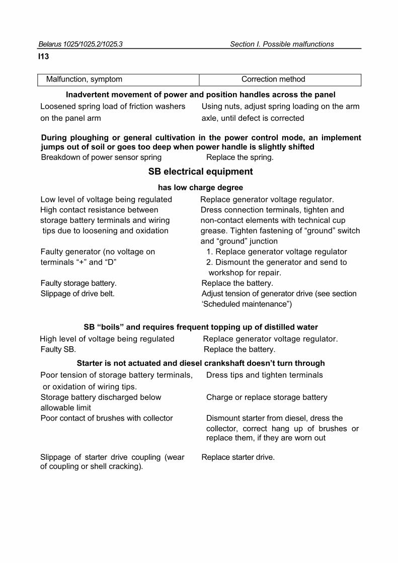
Belarus 1025/1025.2/1025.3 Section I. Possible malfunctions
I13
Malfunction, symptom Correction method
Inadvertent movement of power and position handles across the panel Loosened spring load of friction washers Using nuts, adjust spring loading on the arm on the panel arm axle, until defect is corrected
During ploughing or general cultivation in the power control mode, an implement jumps out of soil or goes too deep when power handle is slightly shifted Breakdown of power sensor spring Replace the spring.
SB electrical equipment has low charge degree
Low level of voltage being regulated Replace generator voltage regulator. High contact resistance between Dress connection terminals, tighten and storage battery terminals and wiring non-contact elements with technical cup tips due to loosening and oxidation grease. Tighten fastening of “ground” switch and “ground” junction Faulty generator (no voltage on 1. Replace generator voltage regulator terminals “+” and “D” 2. Dismount the generator and send to workshop for repair. Faulty storage battery. Replace the battery. Slippage of drive belt. Adjust tension of generator drive (see section ‘Scheduled maintenance”)
SB “boils” and requires frequent topping up of distilled water
High level of voltage being regulated Replace generator voltage regulator. Faulty SB. Replace the battery.
Starter is not actuated and diesel crankshaft doesn’t turn through
Poor tension of storage battery terminals, Dress tips and tighten terminals or oxidation of wiring tips. Storage battery discharged below Charge or replace storage battery allowable limit Poor contact of brushes with collector Dismount starter from diesel, dress the
collector, correct hang up of brushes or replace them, if they are worn out
Slippage of starter drive coupling (wear of coupling or shell cracking).
Replace starter drive.
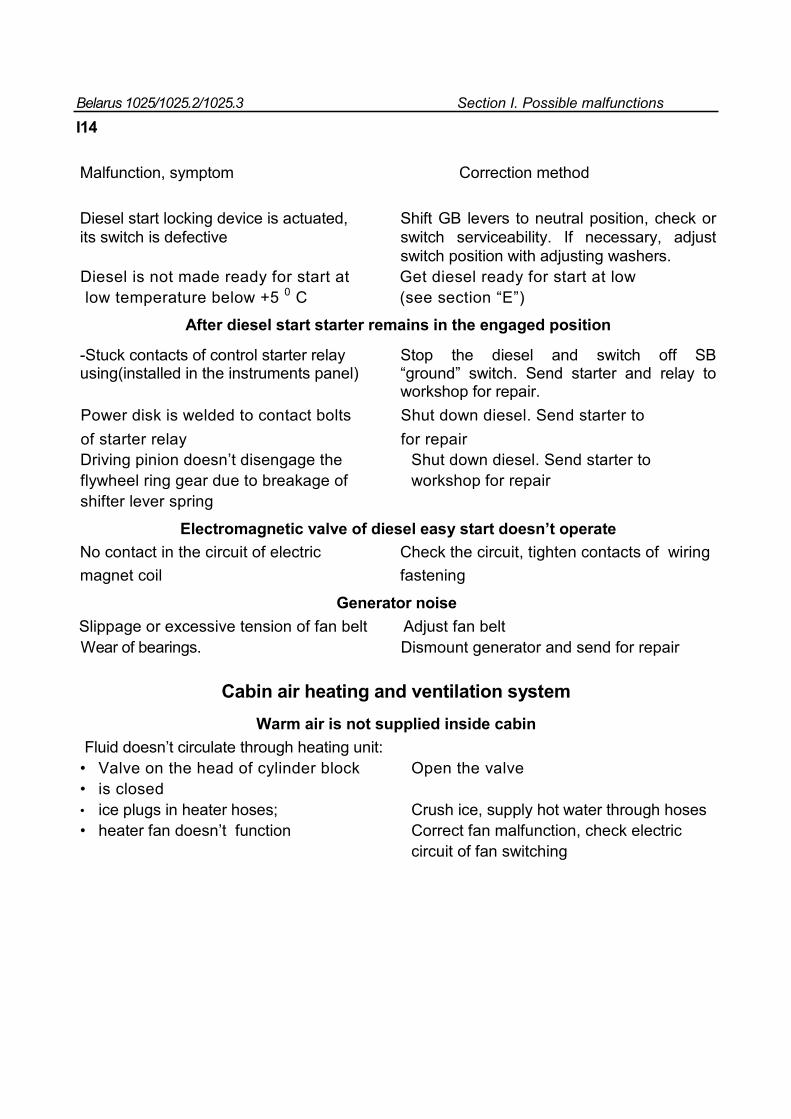
Belarus 1025/1025.2/1025.3 Section I. Possible malfunctions
I14
Malfunction, symptom Correction method
Diesel start locking device is actuated, Shift GB levers to neutral position, check or its switch is defective switch serviceability. If necessary, adjust switch position with adjusting washers. Diesel is not made ready for start at Get diesel ready for start at low low temperature below +5 0 C (see section “E”)
After diesel start starter remains in the engaged position
-Stuck contacts of control starter relay Stop the diesel and switch off SB using(installed in the instruments panel) “ground” switch. Send starter and relay to workshop for repair. Power disk is welded to contact bolts Shut down diesel. Send starter to of starter relay for repair Driving pinion doesn’t disengage the Shut down diesel. Send starter to flywheel ring gear due to breakage of workshop for repair shifter lever spring
Electromagnetic valve of diesel easy start doesn’t operate
No contact in the circuit of electric Check the circuit, tighten contacts of wiring magnet coil fastening
Generator noise
Slippage or excessive tension of fan belt Adjust fan belt Wear of bearings. Dismount generator and send for repair
Cabin air heating and ventilation system Warm air is not supplied inside cabin
Fluid doesn’t circulate through heating unit: • Valve on the head of cylinder block Open the valve • is closed • ice plugs in heater hoses; Crush ice, supply hot water through hoses • heater fan doesn’t function Correct fan malfunction, check electric circuit of fan switching
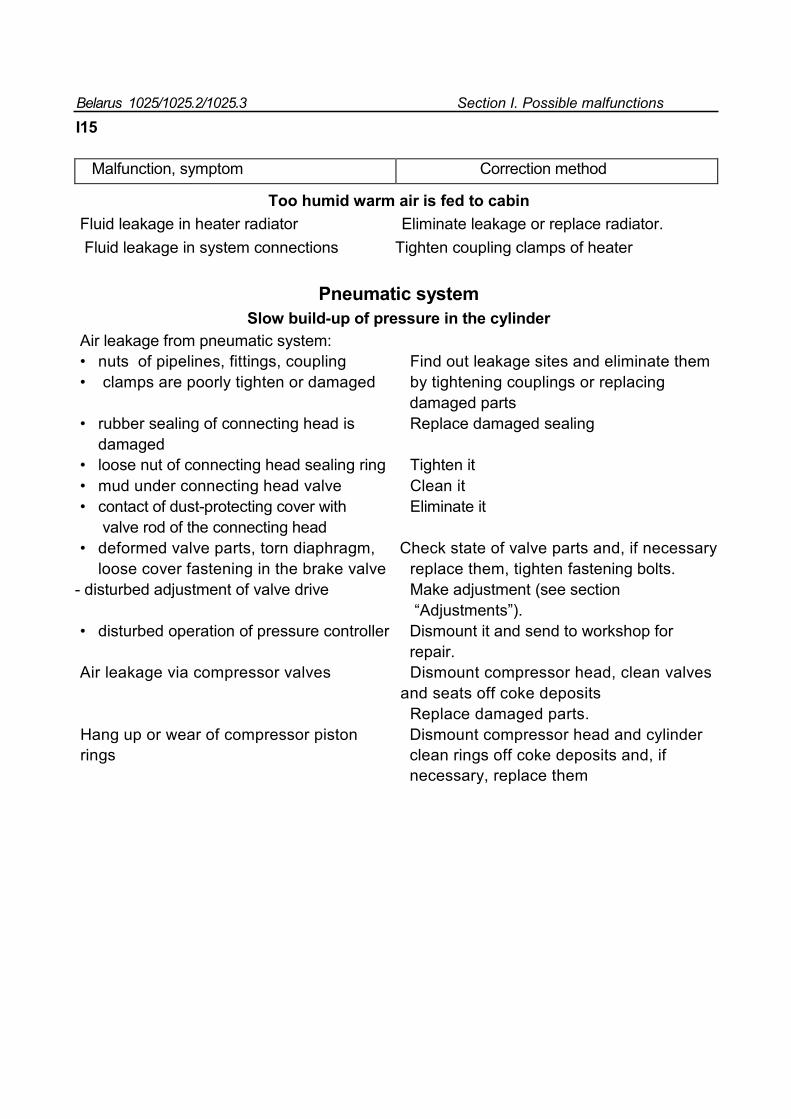
Belarus 1025/1025.2/1025.3 Section I. Possible malfunctions
I15
Malfunction, symptom Correction method
Too humid warm air is fed to cabin
Fluid leakage in heater radiator Eliminate leakage or replace radiator. Fluid leakage in system connections Tighten coupling clamps of heater
Pneumatic system Slow build-up of pressure in the cylinder
Air leakage from pneumatic system: • nuts of pipelines, fittings, coupling Find out leakage sites and eliminate them • clamps are poorly tighten or damaged by tightening couplings or replacing
damaged parts • rubber sealing of connecting head is Replace damaged sealing
damaged • loose nut of connecting head sealing ring Tighten it • mud under connecting head valve Clean it • contact of dust-protecting cover with Eliminate it
valve rod of the connecting head • deformed valve parts, torn diaphragm, Check state of valve parts and, if necessary
loose cover fastening in the brake valve replace them, tighten fastening bolts. - disturbed adjustment of valve drive Make adjustment (see section “Adjustments”). • disturbed operation of pressure controller Dismount it and send to workshop for repair. Air leakage via compressor valves Dismount compressor head, clean valves and seats off coke deposits Replace damaged parts. Hang up or wear of compressor piston Dismount compressor head and cylinder rings clean rings off coke deposits and, if necessary, replace them
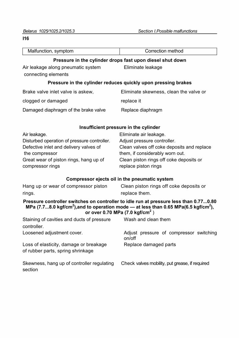
Belarus 1025/1025.2/1025.3 Section I.Possible malfunctions
I16
Malfunction, symptom Correction method
Pressure in the cylinder drops fast upon diesel shut down
Air leakage along pneumatic system Eliminate leakage connecting elements
Pressure in the cylinder reduces quickly upon pressing brakes
Brake valve inlet valve is askew, Eliminate skewness, clean the valve or
clogged or damaged replace it
Damaged diaphragm of the brake valve Replace diaphragm
Insufficient pressure in the cylinder
Air leakage. Eliminate air leakage. Disturbed operation of pressure controller. Adjust pressure controller. Defective inlet and delivery valves of Clean valves off coke deposits and replace the compressor them, if considerably worn out. Great wear of piston rings, hang up of Clean piston rings off coke deposits or compressor rings replace piston rings
Compressor ejects oil in the pneumatic system
Hang up or wear of compressor piston Clean piston rings off coke deposits or rings. replace them.
Pressure controller switches on controller to idle run at pressure less than 0.77...0.80 MPa (7.7...8.0 kgf/cm2),and to operation mode — at less than 0.65 MPa(6.5 kgf/cm2),
or over 0.70 MPa (7.0 kgf/cm2 ) Staining of cavities and ducts of pressure Wash and clean them controller. Loosened adjustment cover. Adjust pressure of compressor switching
on/off Loss of elasticity, damage or breakage Replace damaged parts of rubber parts, spring shrinkage Skewness, hang up of controller regulating Check valves mobility, put grease, if required section
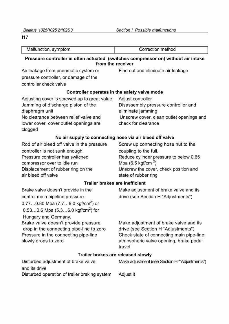
Belarus 1025/1025.2/1025.3 Section I. Possible malfunctions
I17
Malfunction, symptom Correction method
Pressure controller is often actuated (switches compressor on) without air intake from the receiver
Air leakage from pneumatic system or Find out and eliminate air leakage pressure controller, or damage of the controller check valve
Controller operates in the safety valve mode
Adjusting cover is screwed up to great value Adjust controller Jamming of discharge piston of the Disassembly pressure controller and diaphragm unit eliminate jamming No clearance between relief valve and Unscrew cover, clean outlet openings and lower cover, cover outlet openings are check for clearance clogged
No air supply to connecting hose via air bleed off valve
Rod of air bleed off valve in the pressure Screw up connecting hose nut to the controller is not sunk enough. coupling to the full. Pressure controller has switched Reduce cylinder pressure to below 0.65 compressor over to idle run Mpa (6.5 kgf/cm 2) Displacement of rubber ring on the Unscrew the cover, check position and air bleed off valve state of rubber ring
Trailer brakes are inefficient Brake valve doesn’t provide in the Make adjustment of brake valve and its control main pipeline pressure drive (see Section H “Adjustments”) 0.77…0.80 Mpa (7.7…8.0 kgf/cm2) or 0.53…0.6 Mpa (5.3…6.0 kgf/cm2) for Hungary and Germany. Brake valve doesn’t provide pressure Make adjustment of brake valve and its drop in the connecting pipe-line to zero drive (see Section H “Adjustments”) Pressure in the connecting pipe-line Check state of connecting main pipe-line; slowly drops to zero atmospheric valve opening, brake pedal travel.
Trailer brakes are released slowly
Disturbed adjustment of brake valve Make adjustment (see Section H ““Adjustments”) and its drive Disturbed operation of trailer braking system Adjust it
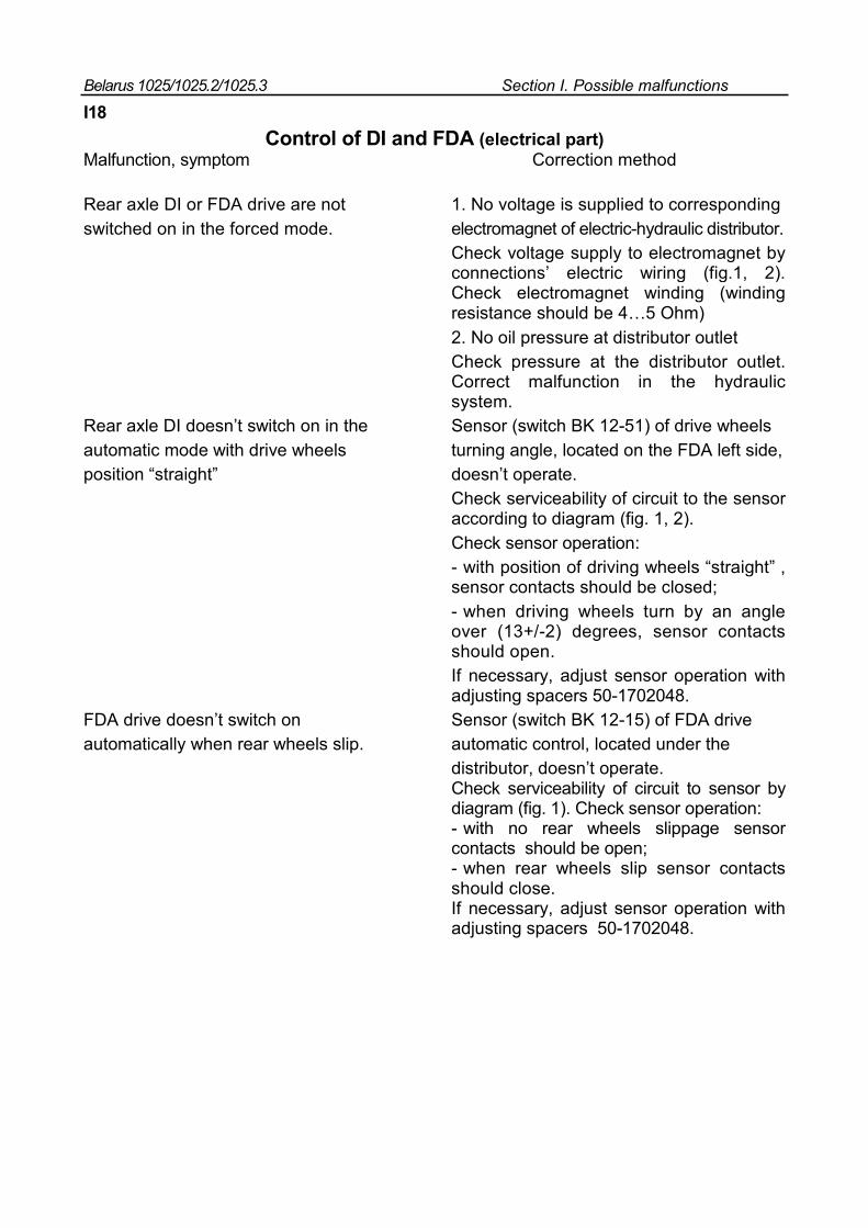
Belarus 1025/1025.2/1025.3 Section I. Possible malfunctions
I18
Control of DI and FDA (electrical part) Malfunction, symptom Correction method
Rear axle DI or FDA drive are not 1. No voltage is supplied to corresponding switched on in the forced mode. electromagnet of electric-hydraulic distributor.
Check voltage supply to electromagnet by connections’ electric wiring (fig.1, 2). Check electromagnet winding (winding resistance should be 4…5 Ohm) 2. No oil pressure at distributor outlet Check pressure at the distributor outlet. Correct malfunction in the hydraulic system.
Rear axle DI doesn’t switch on in the Sensor (switch BK 12-51) of drive wheels automatic mode with drive wheels turning angle, located on the FDA left side, position “straight” doesn’t operate.
Check serviceability of circuit to the sensor according to diagram (fig. 1, 2). Check sensor operation: - with position of driving wheels “straight” , sensor contacts should be closed; - when driving wheels turn by an angle over (13+/-2) degrees, sensor contacts should open. If necessary, adjust sensor operation with adjusting spacers 50-1702048.
FDA drive doesn’t switch on Sensor (switch BK 12-15) of FDA drive automatically when rear wheels slip. automatic control, located under the distributor, doesn’t operate.
Check serviceability of circuit to sensor by diagram (fig. 1). Check sensor operation: - with no rear wheels slippage sensor contacts should be open; - when rear wheels slip sensor contacts should close. If necessary, adjust sensor operation with adjusting spacers 50-1702048.
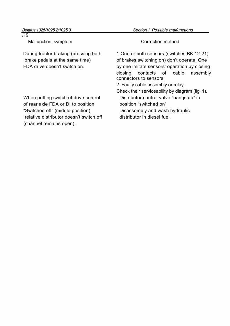
Belarus 1025/1025.2/1025.3 Section I. Possible malfunctions I19
Malfunction, symptom Correction method
During tractor braking (pressing both 1.One or both sensors (switches BK 12-21) brake pedals at the same time) of brakes switching on) don’t operate. One FDA drive doesn’t switch on. by one imitate sensors’ operation by closing
closing contacts of cable assembly connectors to sensors. 2. Faulty cable assembly or relay. Check their serviceability by diagram (fig. 1).
When putting switch of drive control Distributor control valve “hangs up” in of rear axle FDA or DI to position position “switched on” “Switched off” (middle position) Disassembly and wash hydraulic relative distributor doesn’t switch off distributor in diesel fuel. (channel remains open).
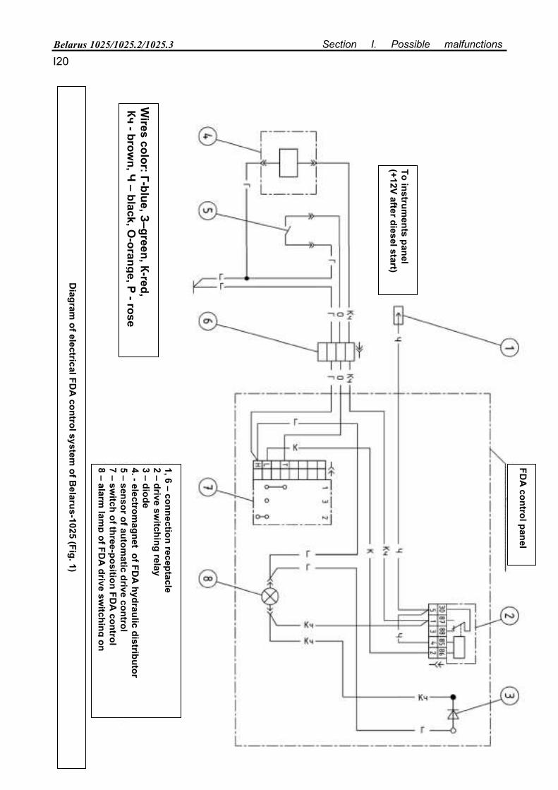
Belarus 1025/1025.2/1025.3 Section I. Possible malfunctions
I20
Diagram
of electrical FDA
control system of B
elarus-1025 (Fig. 1)
Wires color: Г-blue, З–green, К-red,
Кч - brown, Ч
– black, O-orange, Р - rose
FDA
control panel
To instruments panel
(+12V after diesel start)
1, 6 – connection receptacle 2 – drive sw
itching relay 3 – diode 4. - electrom
agnet of FDA
hydraulic distributor 5 – sensor of autom
atic drive control 7 – sw
itch of three-position FDA
control 8 – alarm
lamp of FD
A drive sw
itching on
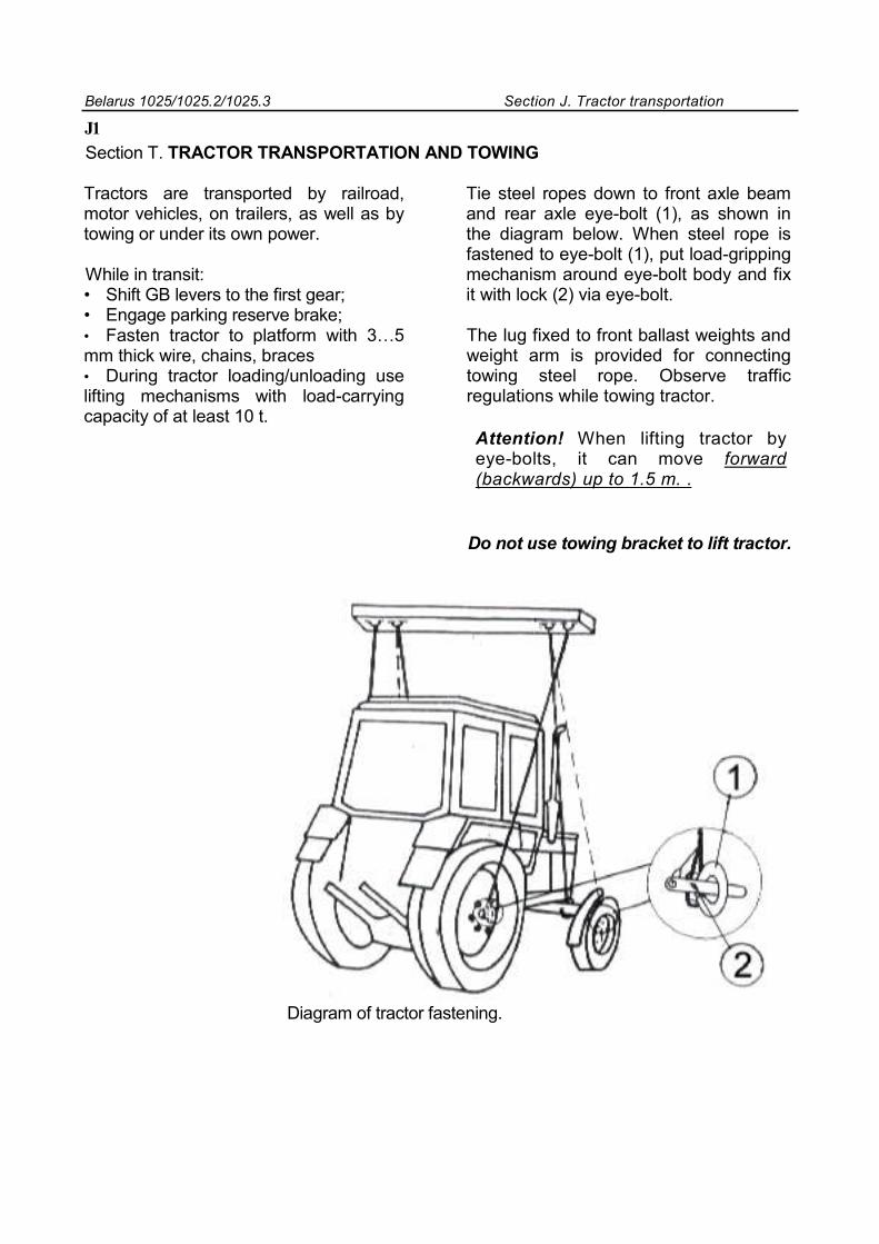
Belarus 1025/1025.2/1025.3 Section J. Tractor transportation
J1
Section Т. TRACTOR TRANSPORTATION AND TOWING
Tractors are transported by railroad, motor vehicles, on trailers, as well as by towing or under its own power.
While in transit: • Shift GB levers to the first gear; • Engage parking reserve brake; • Fasten tractor to platform with 3…5 mm thick wire, chains, braces • During tractor loading/unloading use lifting mechanisms with load-carrying capacity of at least 10 t.
Tie steel ropes down to front axle beam and rear axle eye-bolt (1), as shown in the diagram below. When steel rope is fastened to eye-bolt (1), put load-gripping mechanism around eye-bolt body and fix it with lock (2) via eye-bolt.
The lug fixed to front ballast weights and weight arm is provided for connecting towing steel rope. Observe traffic regulations while towing tractor.
Attention! When lifting tractor by eye-bolts, it can move forward (backwards) up to 1.5 m. .
Do not use towing bracket to lift tractor.
Diagram of tractor fastening.
Belarus-1025/1025.2/1025.3 Section K. Storage regulations
Section K STORAGE REGULATIONS
If indoors premises are not available, tractors may be stored on outdoor special sites, with obligatory preservation, sealing and components dismounting, that require warehousing.
Put tractors in the inter-shift storage, if their operation is interrupted for up to 10 days, short-term storage if duration of idle interval is from ten days to two months, and long-term storage if interruption of use lasts for over two months. Start preparation for short-term storage straight after works completion, and for long-term storage – not later than ten days after works termination. Before putting to storage, check technical state of the tractor. It must undergo scheduled maintenance.
Technological maintenance when preparing tractor for long-term storage includes:
Cleaning and washing , dismounting and preparing for storage tractor components subject to storage in specially equipped warehouses, sealing of openings and cavities from ingress of moisture and dust, tractor and its components’ preservation, putting tractor on supports (plates).
After operation tractor is cleaned off dust, mud, oil leaks, vegetation and other remains. Components where water is not allowed (generators, relays, etc.), are protected with sheathes. After tractor is cleaned and washed, it is blown off with compressed air to remove moisture. Damaged painting is restored by putting varnish and paint coating or protective grease.
Paint coating should be deposited according to GOST 6572-91.
With long-term outdoor storage, electrical equipment, components made of rubber, polymer materials and textile ( hoses of hydraulic systems, etc, are dismounted, prepared for storage and sent to warehouse. Fastening parts of dismounted tractor components are reinstalled. Electrical equipment (headlights, generator, starter, storage batteries) are cleaned, blown with compressed air, terminals are coated with protective grease.
When putting tractor in long-term storage, descale and wash diesel cooling system, lubricate all tractor assemblies according to the lubrication chart. Drain oil and fill fresh oil with additives to the control level in diesel casing, air purifier sump, cases of gear box, rear and front axles, wheel reduction gear, intermediate supports, oil tank of the hydraulic system. Run tractor in for 10-15 minutes. Drain cooling fluid out of the cooling system, and cabin cooling and air heating system. Drain fuel out of the fuel system, rinse inside tanks’ surfaces with inhibitor lubricants and tightly close filling necks. Use preservation mixture to preserve fuel system and diesel cylinders. Put storage batteries in long-term storage after conducting control-training cycle in accordance with GOST 9590-76. Exposed joints, threaded connections, steering trapezoids, grooved surfaces of PTO drive end and gimbal gears, extended sections of cylinders’ and suspensions’ rods, mechanisms for adjusting wheels span
Belarus-1025/1025.2/1025.3 of front and rear wheel should be preserved. Tightly cover fuel tank filling neck, diesel breathers’ openings, transmission, hydraulic systems, diesel exhaust pipe and inlet air purifier pipe, relative openings after starter removal, and other cavities, through which atmospheric precipitation may get inside inner cavities of tractor assembly units, with covers, polyethylene film sacks or other special accessories. Shift levers and pedals to position excluding spontaneous switching of tractor units and assemblies.
Pneumatic tires may be stored in the unloaded state outdoors on tractors put on supports. Tires’ surfaces are coated with protective substance. Pressure in tires during indoors and outdoors storage should be reduce down to 70% of the rated value. Exterior surfaces of the hydraulic system flexible hoses are cleaned off mud and oil. Hoses may be kept on the machine. In this case they are coated with protective substance or wrapped with insulating material (wax paper, polyethylene film, etc). All openings, slots, cavities (filling necks of tanks, and transmission, reduction gears, openings of hydraulic systems’ breathers, engine exhaust pipe and others), through which atmospheric precipitation can get inside tractor cavities, are tightly covered with covers or stopper plugs. To provide free water drain from the cooling system and condensate, leave draining fixtures open. Cabin hoods and doors should be closed
Maintenance during storage includes checking if machines are properly placed on supports (plates) (absence of cocking), completeness, air pressure in tires, air tightness, state of
Section K. Storage regulations anticorrosion coatings (protective grease, paint integrity, absence of corrosion (integrity and strength of sheathes and covers). Detected defects should be corrected.
Tractor technological maintenance when removing from storage includes taking off supports, cleaning and, if required, depreservation of tractor, its components, reinstallation of dismounted components, tools, removal of sealing fixtures, checking operation and adjustments of tractor and its assemblies.
Requirements for inter-shift storage of machines
Tractor may be stored on storage yards, and inter-shift storage grounds, or directly on works execution sites. All openings, through which atmospheric precipitation can get inside tractor cavities, should be tightly covered .Storage batteries should be switched off.
Requirements for short-term machines storage
Put tractor in storage in complete without dismounting parts and assembly units.
Disconnect storage batteries. Electrolyte level and density should correspond to recommendations for storage and maintenance of storage batteries. If tractor is stored at low temperatures or over one month, storage batteries are dismounted and sent to warehouse.
Requirements for outdoors long-term storage
Engine preparation for putting in long-term storage includes preservation of surface of parts inside an engine (inside preservation) and washing.
Belarus-1025/1025.2/1025.3 the cooling system, sealing of inside surfaces, preservation of outside unpainted engine surfaces (outside preservation), and if hood is not provided, engine packing with polymer film sheath. Preservation of empty fuel tanks includes the use of volatile inhibitors. Air purifier is cleaned and washed, and sump is filled with operation preservation oil.
Threaded connections of mounting mechanism, steering trapezoids, hydraulic systems and so on are cleaned and greased.
Preservation
Preservation provides provisional anticorrosion protection of tractor assemblies and systems from ambient exposure in the process of tractor transportation and storage. Tractor surfaces subject to preservation are cleaned from mechanical staining, degreased and dried up. Unpainted inside and outside galvanized surfaces, specific assemblies of tractor and cabin are conserved with corrosion-proof oil RUST BAN 397. SUMIDERA 397. Material consumption is 0.02-0.03 kg per tractor.
Inside diesel surfaces are conserved after tractor running in by filling anticorrosion inhibitor PFINDER АР 241. CORTEK VCI 329 via coarse filter to fill cavities with preservation additive. Material consumption is 0.05 kg per tractor. Preservation of fuel tank inside surfaces is carried out by sputtering after their manufacture and before coating with preservation oil RUST BAN 335. ML -5888, instruments panel – after assembly by sputtering corrosion-proof oil RUST BAN 397, SUMIDERA 397 on inside panel surfaces. PTO drive ends are preserved by greasing with corrosion-protective
Section K. Storage regulations oil RUST BAN 335, ML -5888. Material consumption is 0.1 kg per tractor.
Some assemblies (monocyclone, necks of radiator and fuel tank, breathers, cylinders’ rods) are sealed with polyethylene sheathes. Consumption of material is 0.66 kg per tractor.
Materials used provide protection of tractor and its assemblies for the period of storage and transportation within one year. Before putting tractor into operation remove polyethylene sheathes, clean outside tractor surfaces off preservation material using cloth soaked in solvent under GOST3134-78.
Outside tractor and its assemblies preservation is made by lubrication of surfaces using brush or sputtering by means of paint sprayer.
Inside tractor preservation is carried out by filling cavities with preservation mixture and subsequent engine operation.
Depreservation
Depreservation method is chosen depending on preservation materials used. Surfaces under preservation have to be wiped with cleaning cloth soaked with low-viscous oils, solvents, or washed away with washing water-soluble detergents. Sealed assembles should be stripped off insulation materials (film, paper). Inside surfaces under preservation need no depreservation.
Represervation
Tractor represervation is carried out in case conservation defects are detected in the process of storage or upon expiration of protection life.
Belarus-1025/1025.2/1025.3 During tractor operation and inter-shift, short-term and long-term storage, means and methods of preservation, storage conditions are chosen by an enterprise, that maintains tractor in compliance with GOST 7751-85. Inside surfaces may also be preserved with general-purpose preservation grease KS-U according to Specifications TU RB 600125053.019-2004. During outdoor storage specific surfaces are preserved with grease «BELA-KOR» grade А according to TU-RB 600125053-020-2004.
Putting tractor into operation after long-term storage
Remove grease off surfaces under preservation. Dismount protective covers, plugs, special accessories and reinstall earlier removed parts. Before mounting parts clean them off grease and dust. Drain sediment out of all vessels, fill them with operation fluids and, if necessary, top up to control level.
Lubricate all tractor mechanisms according to lubrication chart. Fill fuel tanks with fuel. De-preservation of the fuel system and diesel cylinders is made by starting diesel. Fill the system with cooling fluid. Carry out scheduled maintenance. Turn through diesel crankshaft without supply of fuel by several turns and, making sure crankshaft rotates properly, start diesel for 5-10 minutes, gradually bring crankshaft rotation speed from minimum to rated value. Run in tractor for 15-20 minutes. Correct detected faults.
Section K. Storage regulations Safety requirements in preservation
The preservation production process, comprising surfaces preparation, deposition of preservation materials, paper marking and cutting, packing, can be performed only by persons who arrived at the age of eighteen, underwent medical examination, introduction briefing on labor and fire safety, primary briefing on the working place. Preservation remises and sections should be separated from other production premises and equipped with plenum-exhaust ventilation. Materials used for preservation are combustible substances with flash temperature from 170 to 270oC, and should comply with state standards, technical specifications and have quality certificate. Conservation materials being supplied should bear label with material description. Perform preservation operations in special clothes and footwear and use individual protection means. When performing preservation operations, observe personal hygiene rules, dry clean special clothes in time, don’t wash it in emulsions, solvents, kerosine. By the degree of impact on human organism preservation materials are related to moderately dangerous, so use recommended individual protection means while handling materials With prolonged exposure of skin to preservation oils, greases and liquids, it can be injured. White spirit vapors in small concentrations act as weak drug. Large concentration may lead to poisoning. Anticorrosion paper contain corrosion inhibitors causing irritation and inflammation of skin, mucous of nose and eyes. Before starting work put on cotton overalls, robe or apron, make ready individual protection means depending on work conditions and toxicity of substances used. Grease hands with protection paste (creme) and put on cotton and rubber gloves. Before performing work, safe conditions of which are not known, demand to be briefed on safety engineering regulations.
Section L. TRACTOR DISPOSAL Section L.Tractor disposal
When disposing tractor upon expiration of service (operation) life, it is necessary to:
• Drain and in the established order send for processing oils from diesel lubrication system, body of rear axle and wheel reduction gear, gear box, front driving axle, reduction gears of final front wheels gears, hydraulic system oil tank
• Drain cooling fluid from diesel cooling system, cabin heating system and put it in special storage reservoirs;
• Drain diesel fuel from fuel tank and put it in special storage reservoirs;
• Drain sediment from fuel coarse and fine filters;
• Drain electrolyte from tractor SB, put it special storage reservoir and send for processing in the established order;
• Make complete tractor disassembly into parts, having sorted them out into non-metal, steel, cast iron, non-ferrous and precious metals, and send them for processing in the established order;
• Dismounting of parts and assembly units, maintenance of air conditioning system should be carried out by specially trained personnel using equipment for servicing freon refrigerating machines
• During maintenance and regular servicing, fuel and lubricants subject to change and, if necessary, parts and assembly units, should be sent for processing , having sorted them out into groups of materials.
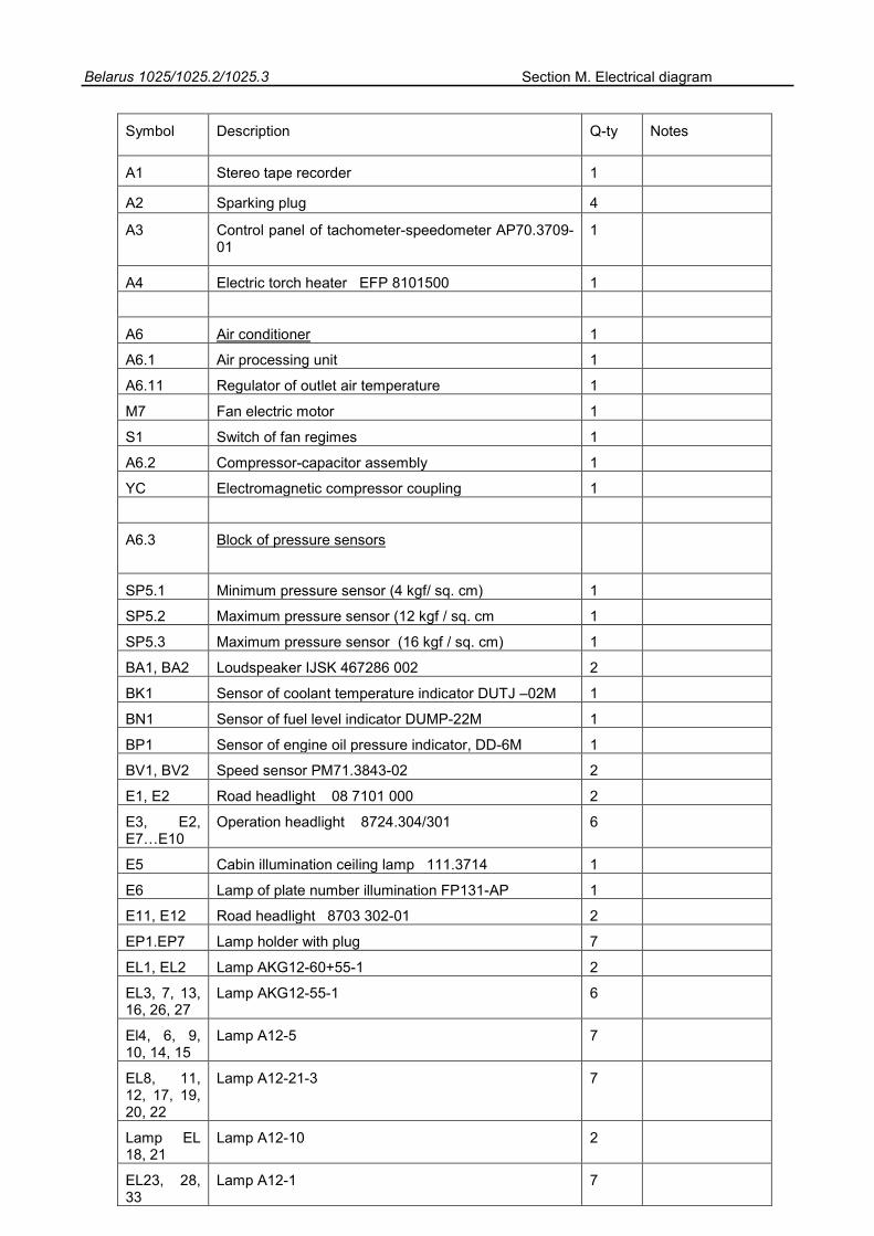
Belarus 1025/1025.2/1025.3 Section M. Electrical diagram
Symbol Description Q-ty Notes
A1 Stereo tape recorder 1
A2 Sparking plug 4
A3 Control panel of tachometer-speedometer AP70.3709-01
1
A4 Electric torch heater EFP 8101500 1
A6 Air conditioner 1
A6.1 Air processing unit 1
A6.11 Regulator of outlet air temperature 1
M7 Fan electric motor 1
S1 Switch of fan regimes 1
A6.2 Compressor-capacitor assembly 1
YC Electromagnetic compressor coupling 1
A6.3 Block of pressure sensors
SP5.1 Minimum pressure sensor (4 kgf/ sq. cm) 1
SP5.2 Maximum pressure sensor (12 kgf / sq. cm 1
SP5.3 Maximum pressure sensor (16 kgf / sq. cm) 1
BA1, BA2 Loudspeaker IJSK 467286 002 2
BK1 Sensor of coolant temperature indicator DUTJ –02M 1
BN1 Sensor of fuel level indicator DUMP-22M 1
BP1 Sensor of engine oil pressure indicator, DD-6M 1
BV1, BV2 Speed sensor PM71.3843-02 2
E1, E2 Road headlight 08 7101 000 2
E3, E2, E7…E10
Operation headlight 8724.304/301 6
E5 Cabin illumination ceiling lamp 111.3714 1
E6 Lamp of plate number illumination FP131-AP 1
E11, E12 Road headlight 8703 302-01 2
EP1.EP7 Lamp holder with plug 7
EL1, EL2 Lamp AKG12-60+55-1 2
EL3, 7, 13, 16, 26, 27
Lamp AKG12-55-1 6
El4, 6, 9, 10, 14, 15
Lamp A12-5 7
EL8, 11, 12, 17, 19, 20, 22
Lamp A12-21-3 7
Lamp EL 18, 21
Lamp A12-10 2
EL23, 28, 33
Lamp A12-1 7
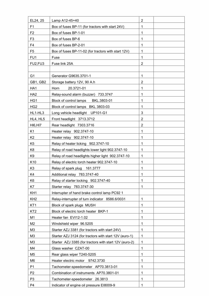
EL24, 25 Lamp A12-45+40 2
F1 Box of fuses BP-11 (for tractors with start 24V) 1
F2 Box of fuses BP-1-01 1
F3 Box of fuses BP-6 1
F4 Box of fuses BP-2-01 1
F5 Box of fuses BP-11-02 (for tractors with start 12V) 1
FU1 Fuse 1
FU2,FU3 Fuse link 25A 2
G1 Generator G9635.3701-1 1
GB1, GB2 Storage battery 12V, 90 A.h 2
HA1 Horn 20.3721-01 1
HA2 Relay-sound alarm (buzzer) 733.3747 1
HG1 Block of control lamps BKL.3803-01 1
HG2 Block of control lamps BKL 3803-03 1
HL1-HL3 Long vehicle headlight UP101-G1 3
HL4, HL5 Front headlight 3713.3712 2
Hl6,Hl7 Rear headlight 7303.3716 2
K1 Heater relay 902.3747-10 1
K2 Heater relay 902.3747-10 1
K5 Relay of heater licking 902.3747-10 1
K8 Relay of road headlights lower light 902.3747-10 1
K9 Relay of road headlights higher light 902.3747-10 1
K10 Relay of electric torch heater 902.3747-10 1
K3 Relay of spark plug 161.3777 1
K4 Additional relay 783.3747-40 1
K6 Relay of starter locking 902.3747-40 1
K7 Starter relay 783.3747-30 1
KH1 Interrupter of hand brake control lamp PC92 1
KH2 Relay-interrupter of turn indicator 8586.6/0031 1
KT1 Block of spark plugs MUSH 1
KT2 Block of electric torch heater BKP-1 1
M1 Heater fan EVI12-1.02 1
M2 Windshield wiper 96.5205 1
M3 Starter AZJ 3381 (for tractors with start 24V) 1
M3 Starter AZJ 3124 (for tractors with start 12V (euro-1) 1
M3 Starter AZJ 3385 (for tractors with start 12V (euro-2) 1
M4 Glass washer CZAT-00 1
M5 Rear glass wiper T240-5205 1
M6 Heater electric motor 9742.3730 1
P1 Tachometer-speedometer AP70.3813-01 1
P2 Combination of instruments AP70.3801-01 1
P3 Tachometer-speedometer 26.3813 1
P4 Indicator of engine oil pressure EI8009-9 1
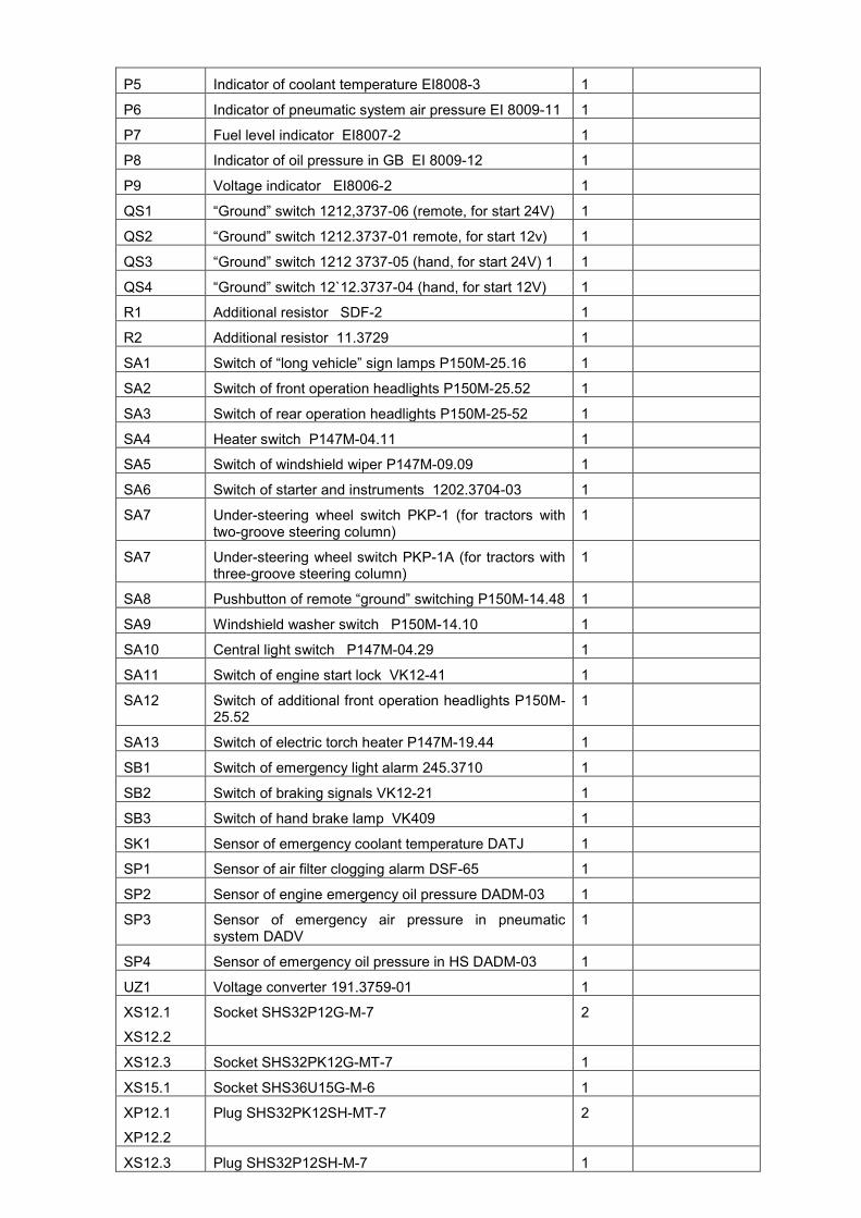
P5 Indicator of coolant temperature EI8008-3 1
P6 Indicator of pneumatic system air pressure EI 8009-11 1
P7 Fuel level indicator EI8007-2 1
P8 Indicator of oil pressure in GB EI 8009-12 1
P9 Voltage indicator EI8006-2 1
QS1 “Ground” switch 1212,3737-06 (remote, for start 24V) 1
QS2 “Ground” switch 1212.3737-01 remote, for start 12v) 1
QS3 “Ground” switch 1212 3737-05 (hand, for start 24V) 1 1
QS4 “Ground” switch 12`12.3737-04 (hand, for start 12V) 1
R1 Additional resistor SDF-2 1
R2 Additional resistor 11.3729 1
SA1 Switch of “long vehicle” sign lamps P150M-25.16 1
SA2 Switch of front operation headlights P150M-25.52 1
SA3 Switch of rear operation headlights P150M-25-52 1
SA4 Heater switch P147M-04.11 1
SA5 Switch of windshield wiper P147M-09.09 1
SA6 Switch of starter and instruments 1202.3704-03 1
SA7 Under-steering wheel switch PKP-1 (for tractors with two-groove steering column)
1
SA7 Under-steering wheel switch PKP-1A (for tractors with three-groove steering column)
1
SA8 Pushbutton of remote “ground” switching P150M-14.48 1
SA9 Windshield washer switch P150M-14.10 1
SA10 Central light switch P147M-04.29 1
SA11 Switch of engine start lock VK12-41 1
SA12 Switch of additional front operation headlights P150M-25.52
1
SA13 Switch of electric torch heater P147M-19.44 1
SB1 Switch of emergency light alarm 245.3710 1
SB2 Switch of braking signals VK12-21 1
SB3 Switch of hand brake lamp VK409 1
SK1 Sensor of emergency coolant temperature DATJ 1
SP1 Sensor of air filter clogging alarm DSF-65 1
SP2 Sensor of engine emergency oil pressure DADM-03 1
SP3 Sensor of emergency air pressure in pneumatic system DADV
1
SP4 Sensor of emergency oil pressure in HS DADM-03 1
UZ1 Voltage converter 191.3759-01 1
XS12.1
XS12.2
Socket SHS32P12G-M-7 2
XS12.3 Socket SHS32PK12G-MT-7 1
XS15.1 Socket SHS36U15G-M-6 1
XP12.1
XP12.2
Plug SHS32PK12SH-MT-7 2
XS12.3 Plug SHS32P12SH-M-7 1

XS15.1 Plug SHS36PK15SH-MT-6 1
XA9.1 Combined socket P9-1 1
XT1 Block of branches BP-11-01 1
XT2.1XT2.2
Connecting panel P14.3723 2
XT13.1XT3.2
Connecting panel P15.3723 2
WA1 Aerial 1

Belarus 1025/1025.2/1025.3 Section M. Electrical diagram
Diagram
of tractor electrical connections (Page 1)
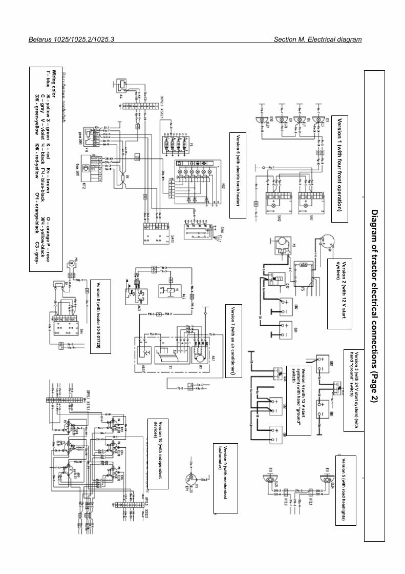
Belarus 1025/1025.2/1025.3 Section M. Electrical diagram
Diagram
of tractor electrical connections (Page 2)
Version 1 (with four front operation)
Version 2 (with 12 V start
system)
Version 3 (with 24 V start system
) (with
hand “ground” switch)
Version 4 (w
ith 12 V start system
) (with hand “ground”
switch)
Version 5 (with road headlights)
Version 9 (with m
echanical tachom
eter)
Version 10 (w
ith independent devices)
Version 7 (with an air conditioner))
Version 8 (with heater 80-8 01720)
Version 6 (with electric torch heater)
Wiring color
Г– blue Ж
- yellow З – green К – red
Кч – brown
O – orange Р – rose
С
– gray V – violet
Ч – black
ГЧ - blue-black
ЖЧ
- yellow-black
ЗЖ
- green-yellow
КЖ - red-yellow
О
Ч - orange-black
СЗ - gray-