
BEHAVIOR OF ROUND TIMBER BOLTED JOINTS UNDER TENSION … · BEHAVIOR OF ROUND TIMBER BOLTED JOINTS...
12
819 WOOD RESEARCH 61 (5): 2016 819-830 BEHAVIOR OF ROUND TIMBER BOLTED JOINTS UNDER TENSION LOAD Antonín Lokaj, Kristýna Klajmonová, David Mikolášek Kristýna Vavrušová VšB-Technical University of Ostrava, Faculty of Civil Engineering Department of Building Structures Ostrava, Czech Republic (Received December 2015) ABSTRACT In the current European standards for the design of timber structures, the issue of timber- to-timber joint type is addressed only to squared timber, which makes the pinpointing of the round timber bolted joints carrying capacity near-unfeasible due to the insufficient support in the current standards. There have been made series of tests of round timber joints in different inclinations tensile load to the grainand also the reference tests of squared timber joints to compare the behaviour of this type of joints. Mechanical behaviour of round and squared timber bolted joints were tested in the laboratory of the Faculty of Civil Engineering in Ostrava.This paper presents results of static tests in tension at an angle of 0, 90 and 60° to the grain of squared and round timber bolted joints. Carrying capacity was determined according to the applicable standards and theories of fracture mechanics. Round timber joints were also numerically simulated. The test results of numerical models were then compared with the results of laboratory tests and theoretical calculations. KEYWORDS: Round timber, bolt, joint, carrying capacity, reinforcement. INTRODUCTION The strength of wood varies depending on the force direction related to the orientation of the grains. The highest value reaches the tensile strength parallel to the grain, the average value indicates 120 N∙mm -2 . This high strength is mainly due to the shape of cells and fibrous cell wall structure. Tensile strength perpendicular to the grain is hand the smallest strength of wood at all. The average tensile strength perpendicular to the grain is in the range 2 and 5 N∙mm -2 . This corresponds to 1/20 of the tensile strength of wood parallel to the grain (Gandelová et al. 2009). Low value of tensile strength perpendicular to the grain is caused by orientation of the binding forces. Hydrogen bonds and van der Waals forces connect fibers in the transverse direction.
-
Upload
nguyentuyen -
Category
Documents
-
view
258 -
download
6
Transcript of BEHAVIOR OF ROUND TIMBER BOLTED JOINTS UNDER TENSION … · BEHAVIOR OF ROUND TIMBER BOLTED JOINTS...
819
WOOD RESEARCH 61 (5): 2016 819-830
BEHAVIOR OF ROUND TIMBER BOLTED JOINTS UNDER
TENSION LOAD
Antonín Lokaj, Kristýna Klajmonová, David Mikolášek Kristýna Vavrušová
Všb-Technical University of Ostrava, Faculty of Civil Engineering Department of building Structures
Ostrava, Czech Republic
(Received December 2015)
ABSTRACT
In the current European standards for the design of timber structures, the issue of timber-to-timber joint type is addressed only to squared timber, which makes the pinpointing of the round timber bolted joints carrying capacity near-unfeasible due to the insufficient support in the current standards. There have been made series of tests of round timber joints in different inclinations tensile load to the grainand also the reference tests of squared timber joints to compare the behaviour of this type of joints. Mechanical behaviour of round and squared timber bolted joints were tested in the laboratory of the Faculty of Civil Engineering in Ostrava.This paper presents results of static tests in tension at an angle of 0, 90 and 60° to the grain of squared and round timber bolted joints. Carrying capacity was determined according to the applicable standards and theories of fracture mechanics. Round timber joints were also numerically simulated. The test results of numerical models were then compared with the results of laboratory tests and theoretical calculations.
KEYWORDS: Round timber, bolt, joint, carrying capacity, reinforcement.
INTRODUCTION
The strength of wood varies depending on the force direction related to the orientation of the grains. The highest value reaches the tensile strength parallel to the grain, the average value indicates 120 N∙mm-2. This high strength is mainly due to the shape of cells and fibrous cell wall structure. Tensile strength perpendicular to the grain is hand the smallest strength of wood at all. The average tensile strength perpendicular to the grain is in the range 2 and 5 N∙mm-2. This corresponds to 1/20 of the tensile strength of wood parallel to the grain (Gandelová et al. 2009). Low value of tensile strength perpendicular to the grain is caused by orientation of the binding forces. Hydrogen bonds and van der Waals forces connect fibers in the transverse direction.
820
WOOD RESEARCH
Tensile stress of timber perpendicular to the grain is not desirable in use in the support structure.This paper focuses on the behaviour of round timber bolted joints. In the current European
standards for the design of timber structures (Eurocode 5, 2004), the issue of timber-to-timber joint type is addressed only to squared timber, which makes the pinpointing of the round timber bolted joints carrying capacity near-unfeasible due to the insufficient support in the current standards.To compare the behaviour of this type of connections were made series of laboratory static tests in different inclinations tensile load to the grain. The reference tests of squared timber joints were also carried out. Mechanical behaviour of round and squared timber bolted joints were tested in the laboratory of the Faculty of Civil Engineering in Ostrava. This article links to the previous article (Lokaj et al. 2014).
The issue of round timber is engaged in many research teams. Particularly in Scandinavia, Germany and the Netherlands, the round timber is given greater attention, as evidenced by the scientific publications (blass and Frese 2014, de Vries and Gard 1998) or (Ranta-Maunas 1999). These publications deal with material properties and possibilities of using round wood in structures.
Scientists are also concerned with the behaviour of timber elements joints. Smith tested joints and compared the results with numerical models for different types of material. Test results provide a comparison of experimental results with the code-accepted species values. For this study, a test set-up was developed to examine possible brittle and ductile failure mechanisms of single dowel joints in Laminated Veneer Lumber (LVL), Parallel Strand Lumber (PSL), and Laminated Strand Lumber (LSL), with sawn lumber used as a control case. (Smith et al. 2006). Prediction of the load-carrying capacity of dowel type joints with one dowel under static loading is based on the analysis of fracture in wood contrarily to most engineering methods. This analysis of fractureis based on the yield theory by Daudeville et al. (1999). These experiments, however, relate only tojointsof wooden elementswith squared crosssections. Round timber joints have not yet been subjected to significant research.
MATERIAL AND METHODS
Test samples and testingbecause spruce wood is the most common type of timber in Central Europe, it was used
for test samples. Several nondestructive tests were carried out before the onset of the static tests in the press (Lokaj and Klajmonová 2013). Dimensions of the test samples were adjusted to the equipment possibilities of the laboratory at the Faculty of Civil Engineering. Thus, element length was 450 mm (for tests in tension at an angle of 0°) and 560 mm (for tests in tension at an angle of 60 and 90°) and diameter was 120 mm. The bolts of high strength steel (category 8.8) were used. The connection plates were made of steel S235 with thickness of 8, length of 290 and width of 80 mm. Diameter of holes in steel plates was 22 and diameter in timber elements 20 mm. The distance between holes and the free edge in timber was 140, in steel 50 mm (Klajmonová and Lokaj 2013). Squared timber was used with cross section 60x120 mm, another geometry of joint was the same.
821
Vol. 61 (5): 2016
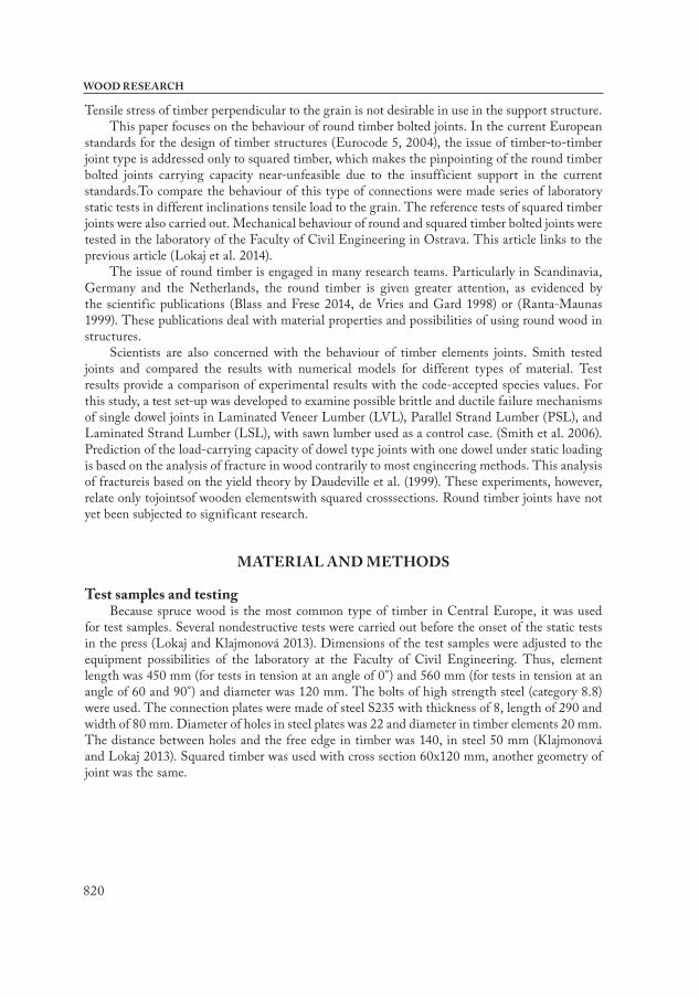
Tab. 1: Characteristics of tested wood.
Samples type Value
Tension orientation at an angle to the grain0° 60° 90°
SD CV SD CV SD CV
Round timber
Number of samples 12 12 12
Density (kg∙m-3) 412.6 42.1 10.2 405.9 26.4 6.5 414.9 46.2 11.1
Moisture content (%) 11.6 1.1 9.4 11.3 1.0 8.9 11.4 1.1 9.6
Squared timber
Number of samples 9 10 12
Density (kg∙m-3) 426.8 13.77 3.2 443.6 14.6 3.3 454.4 50.1 11.0
Moisture content (%) 11.2 0.6 5.3 12.2 0.5 4.1 11.6 0.5 4.3
Fig. 1: Steel product for testing in tension perpendicular to the grain and sample in the press machine.
The special steel element was prepared for testing (Fig. 1). In order for the load direction to be perpendicular (or at an angle 60° to the grain) to the grain, the samples were subjected to a simple tensile test with the tension force being increased gradually. The test parameters were invariable for all samples.
Each round timber sample subjected to a simple tension test had the same test parameters. The tension force in samples loaded parallel to the grain was increased gradually. The selected rate of displacement of the press jaws was optimal. Each specimen failure occurred in time boundaryof 300 ± 120 sec. It corresponds to the current European standard.
Calculation of load carrying capacity of jointFor comparison with applicable European standards (Eurocode 5, 2004) there was carried
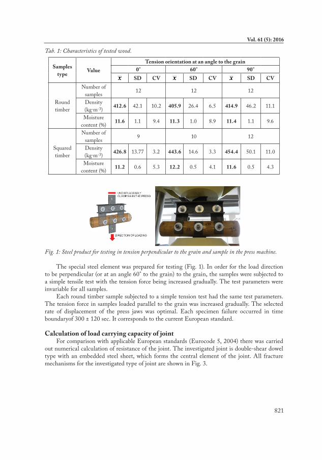
out numerical calculation of resistance of the joint. The investigated joint is double-shear dowel type with an embedded steel sheet, which forms the central element of the joint. All fracture mechanisms for the investigated type of joint are shown in Fig. 3.
822
WOOD RESEARCH
Fig. 2: Fracture mechanisms of double-shear dowel type steel to timber joint.
According to Johansen's theory, that underlies Eurocode 5, the characteristic carrying capacity of one coupling element in one cut at the joint-type steel-timber where the steel plate is the middle joint element, determined by calculating:
(1)
where: Fv,Rk - characteristic load-carrying capacity per shear plane per fastener (N) with rope effect, fh,k - characteristic embedment strength of timber member (N∙mm-2), t1 - timber or board thickness or penetration depth (mm), d - fastener diameter (mm), My,Rk - characteristic fastener yield moment (N∙mm), Fax,Rk - characteristic withdrawal capacity of the fastener.
Relationships mentioned above are based on the theory of Johansen (1949), on this theory there is based calculation of dowel type joints in Eurocode 5. This theory is underscored by a series of laboratory measurements (šmak and Straka 2014). Johansen's theory is based on the assumption that the load bearing is limited by the load capacity in bearing walls of the bolt hole in at least one of the constituent elements, or simultaneous occurrence of the ultimate strength and plastic hinge of dowel.
The mechanism of damage depends on the geometry of connection and properties of construction materials, particularly on a plastic torque of dowel and tensile deformation of the wall of dowel hole in the case of timber or wood-based material.
From equations for determining the carrying capacity of connecting means is evident that calculation for determining the carrying capacity of connections depends on characteristics of wood density and width of the timber below bolt. Decisive parameter is the diameter of the bolt and the material ultimate strength.
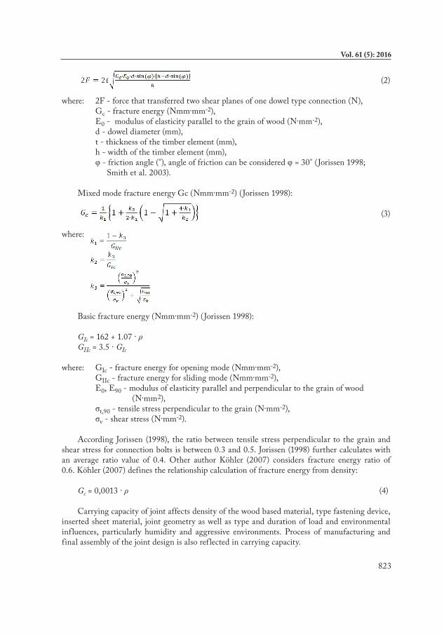
besides failure modes contemplated by Johansen's theory wooden element joints can be also destroyed by brittle fracture. It is the splitting caused by the formation and subsequent development of cracks in the bolt hole. The formula created by Jorissen (1998) can be used to determine the force which express theformula of one dowel-type coupling element carrying capacity:
823
Vol. 61 (5): 2016
(2)
where: 2F - force that transferred two shear planes of one dowel type connection (N), Gc - fracture energy (Nmm∙mm-2), E0 - modulus of elasticity parallel to the grain of wood (N∙mm-2), d - dowel diameter (mm), t - thickness of the timber element (mm), h - width of the timber element (mm), φ - friction angle (°), angle of friction can be considered φ = 30° (Jorissen 1998; Smith et al. 2003).
Mixed mode fracture energy Gc (Nmm∙mm-2) (Jorissen 1998):
(3)
where:
basic fracture energy (Nmm∙mm-2) (Jorissen 1998):
GIc = 162 + 1.07 ∙ ρGIIc = 3.5 ∙ GIc
where: GIc - fracture energy for opening mode (Nmm∙mm-2), GIIc - fracture energy for sliding mode (Nmm∙mm-2), E0, E90 - modulus of elasticity parallel and perpendicular to the grain of wood (N∙mm2), σt,90 - tensile stress perpendicular to the grain (N∙mm-2), σv - shear stress (N∙mm-2).
According Jorissen (1998), the ratio between tensile stress perpendicular to the grain and shear stress for connection bolts is between 0.3 and 0.5. Jorissen (1998) further calculates with an average ratio value of 0.4. Other author Köhler (2007) considers fracture energy ratio of 0.6. Köhler (2007) defines the relationship calculation of fracture energy from density:
Gc = 0,0013 ∙ ρ (4)
Carrying capacity of joint affects density of the wood based material, type fastening device, inserted sheet material, joint geometry as well as type and duration of load and environmental influences, particularly humidity and aggressive environments. Process of manufacturing and final assembly of the joint design is also reflected in carrying capacity.
824
WOOD RESEARCH
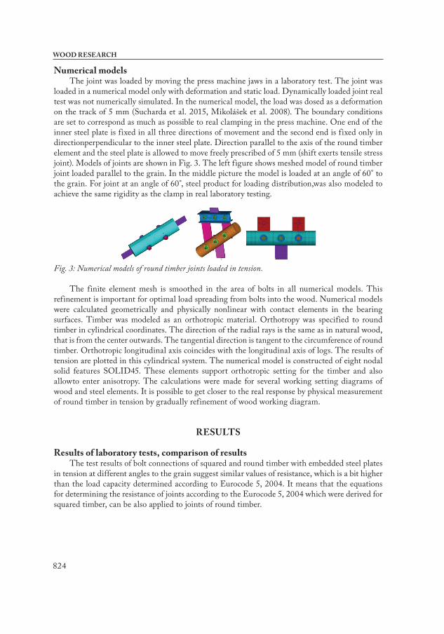
Numerical modelsThe joint was loaded by moving the press machine jaws in a laboratory test. The joint was
loaded in a numerical model only with deformation and static load. Dynamically loaded joint real test was not numerically simulated. In the numerical model, the load was dosed as a deformation on the track of 5 mm (Sucharda et al. 2015, Mikolášek et al. 2008). The boundary conditions are set to correspond as much as possible to real clamping in the press machine. One end of the inner steel plate is fixed in all three directions of movement and the second end is fixed only in directionperpendicular to the inner steel plate. Direction parallel to the axis of the round timber element and the steel plate is allowed to move freely prescribed of 5 mm (shift exerts tensile stress joint). Models of joints are shown in Fig. 3. The left figure shows meshed model of round timber joint loaded parallel to the grain. In the middle picture the model is loaded at an angle of 60° to the grain. For joint at an angle of 60°, steel product for loading distribution,was also modeled to achieve the same rigidity as the clamp in real laboratory testing.
Fig. 3: Numerical models of round timber joints loaded in tension.
The finite element mesh is smoothed in the area of bolts in all numerical models. This refinement is important for optimal load spreading from bolts into the wood. Numerical models were calculated geometrically and physically nonlinear with contact elements in the bearing surfaces. Timber was modeled as an orthotropic material. Orthotropy was specified to round timber in cylindrical coordinates. The direction of the radial rays is the same as in natural wood, that is from the center outwards. The tangential direction is tangent to the circumference of round timber. Orthotropic longitudinal axis coincides with the longitudinal axis of logs. The results of tension are plotted in this cylindrical system. The numerical model is constructed of eight nodal solid features SOLID45. These elements support orthotropic setting for the timber and also allowto enter anisotropy. The calculations were made for several working setting diagrams of wood and steel elements. It is possible to get closer to the real response by physical measurement of round timber in tension by gradually refinement of wood working diagram.
RESULTS
Results of laboratory tests, comparison of resultsThe test results of bolt connections of squared and round timber with embedded steel plates
in tension at different angles to the grain suggest similar values of resistance, which is a bit higher than the load capacity determined according to Eurocode 5, 2004. It means that the equations for determining the resistance of joints according to the Eurocode 5, 2004 which were derived for squared timber, can be also applied to joints of round timber.
825
Vol. 61 (5): 2016
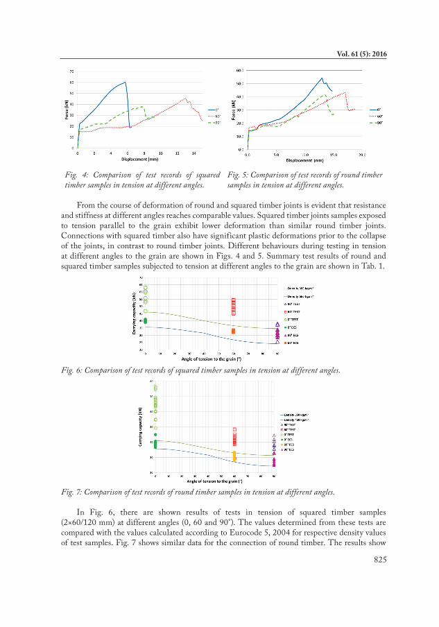
Fig. 4: Comparison of test records of squared timber samples in tension at different angles.
Fig. 5: Comparison of test records of round timber samples in tension at different angles.
From the course of deformation of round and squared timber joints is evident that resistance and stiffness at different angles reaches comparable values. Squared timber joints samples exposed to tension parallel to the grain exhibit lower deformation than similar round timber joints. Connections with squared timber also have significant plastic deformations prior to the collapse of the joints, in contrast to round timber joints. Different behaviours during testing in tension at different angles to the grain are shown in Figs. 4 and 5. Summary test results of round and squared timber samples subjected to tension at different angles to the grain are shown in Tab. 1.
Fig. 6: Comparison of test records of squared timber samples in tension at different angles.
Fig. 7: Comparison of test records of round timber samples in tension at different angles.
In Fig. 6, there are shown results of tests in tension of squared timber samples (2×60/120 mm) at different angles (0, 60 and 90°). The values determined from these tests are compared with the values calculated according to Eurocode 5, 2004 for respective density values of test samples. Fig. 7 shows similar data for the connection of round timber. The results show
826
WOOD RESEARCH
that the load determined according to Eurocode 5, 2004 (without rope effect) is conservative compared withlaboratory test results, but correspondsquite well. Round and squared timber samples damaged by tension under various angles are shown in Figs. 8 and 9.
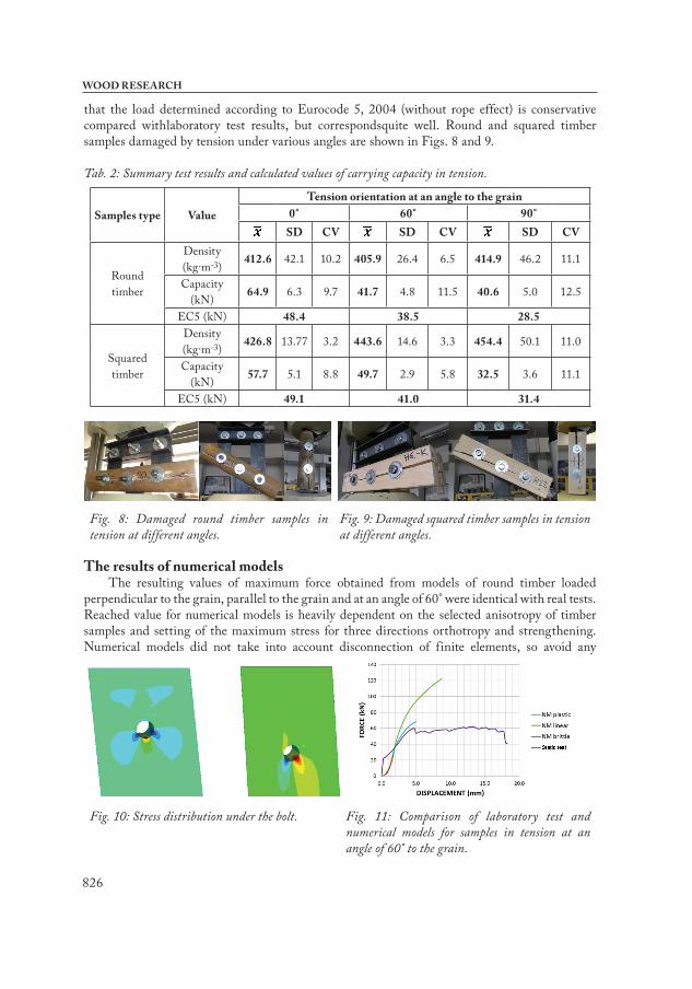
Tab. 2: Summary test results and calculated values of carrying capacity in tension.
Samples type ValueTension orientation at an angle to the grain
0° 60° 90°SD CV SD CV SD CV
Round timber
Density (kg∙m-3) 412.6 42.1 10.2 405.9 26.4 6.5 414.9 46.2 11.1
Capacity (kN) 64.9 6.3 9.7 41.7 4.8 11.5 40.6 5.0 12.5
EC5 (kN) 48.4 38.5 28.5
Squared timber
Density (kg∙m-3) 426.8 13.77 3.2 443.6 14.6 3.3 454.4 50.1 11.0
Capacity (kN) 57.7 5.1 8.8 49.7 2.9 5.8 32.5 3.6 11.1
EC5 (kN) 49.1 41.0 31.4
Fig. 8: Damaged round timber samples in tension at different angles.
Fig. 9: Damaged squared timber samples in tension at different angles.
The results of numerical modelsThe resulting values of maximum force obtained from models of round timber loaded
perpendicular to the grain, parallel to the grain and at an angle of 60° were identical with real tests. Reached value for numerical models is heavily dependent on the selected anisotropy of timber samples and setting of the maximum stress for three directions orthotropy and strengthening. Numerical models did not take into account disconnection of finite elements, so avoid any
Fig. 10: Stress distribution under the bolt. Fig. 11: Comparison of laboratory test and
numerical models for samples in tension at an angle of 60° to the grain.
827
Vol. 61 (5): 2016
tearing of fibers. This effect is simulated in numerical models by HILL ANISOTROPIC HARDENINIG (HAH). The calculation is terminated after reaching a certain stress levels where it is not fulfilled the condition by HAH.
Fig. 10 on the left shows the stress in the radial direction. Here is shown the compressive stress (blue colour [-N∙mm-2]) exerted to a force F = 21 kN. This compressive stress causes the bolt which is pressed into the timber and simultaneously ruptures the timber perpendicularly to the grain (red colour [+N∙mm-2]). Right figure depicts shear stress. It can be seen that the tension is symmetrical in value and spilling over the wood mass but with inverse signs. Shear stress corresponds to the compressive stresses in the left figure. Compressive stress component is trying to break and push the timber of the bolt hole and this creates shear stresses and move perpendicular to the fibers. These components of tensions lead to the destruction of joints in wood for the real test and also for the numerical model. Compressive stress, even when the value exceeds the elastic region, is not reason for loss of carrying capacity of timber. Compressive stress cause dembedment of the structure of wood but the joint is still able to transfer the load.
The results from numerical models confirm that the ratio between the tensile stress perpendicular to the grain and shear stress for spruce varies around a value of 0.45. Tensile stress perpendicular to the grain reaches the value 3.0 and the average shear stress of 6.3 N∙mm-2. Fig. 11 shows the difference between the numerical model and the physical (laboratory static) test. In laboratory test, timber sample can have a residual capacity after reaching the carrying capacity (cracks have occurred perpendicular to the grains there).
It is due to effect transfer of force from the head of the bolt into its sides, and the wood is then stressed primarily in shear. Numerical models are shown in the graph (Fig. 11) in three basic types. The first has configured anisotropic properties close to the plastic behaviour for three orthogonal directions of orthotropy. It leads to a redistribution of deformations and stresses in the joint until the condition HAH. This numerical model is the closest to the laboratory measurement, thanks to its stiffness and the resultant force.
Another numerical model has set only wood as an orthotropic linear material. This model is able to express the largest displacement, but it has not the correct information value because wood does not strain and behaves elastically for large forces. This model is suitable only for forces in the joint, which is designed in elastically region. The third and the last model has set the anisotropy by real working curve of wood. This means that timber behaves brittle plastic and has a small margin (and here is no sudden failure), in tensile and shear. The settings of material constants for tension and shear strengthening were left close to the value of f lexibility for this direction. Setting the pressure was close to plastic response.
The strengthening was multiple less than the corresponding modulus of elasticity for an appropriate direction. This model has behaved very brittle. The calculation was interrupted near the maximum tension perpendicular to the grain.It is necessary to know the respective maximum stress of the fair for the directions for simulated joints and around joints of wooden elements. It is also necessary for each of the original joint and stresses set anisotropic properties of wood according to specific conditions, and if possible also perform laboratory measurements.
CONCLUSIONS
The test results of bolt connections of squared and round timber with embedded steel plates in tension at different angles to the grain suggest similar values of resistance, which corresponds to the load capacity determined according to Eurocode 5, 2004. It means that the equations
828
WOOD RESEARCH
for determining the resistance of joints according to Eurocode 5, 2004 which were derived for squared timber, can be applied to the joints of round timber. Analysis of numerical models showed also good conformity with the calculations of fracture force. Fracture destruction is principal especially for wood joints with higher density. This fact was confirmed by static tests.
ACkNOWLEDgMENT
This outcome has been achieved with funds of Conceptual development of science, research and innovation assigned to Všb - Technical University of Ostrava by Ministry of Education Youth and Sports of the Czech Republic in 2015 under identification number IP2215541.
REFERENCES
1. blass, H.J., Frese, M., 2014: Naturally grown round wood- ideas for an engineering design. In: Materials and Joints in Timber Structures. RILEM book series, Springer, 9: 77-88, ISbN 978-94-007-7810-8.
2. Daudeville, L., Davenne, L., Yasamura, M., 1999: Prediction of the load carving capacity of bolted timber joints. Wood science and technology 33(1): 15-29.
3. Eurocode 5- 2004: Design of timber structures - Part 1-1: General – Common rules and rules for buildings.
4. Gandelová, L., Horáček, P., šlezingerová, J., 2009: Wood science. (Náuka o dřevě). brno, 176 pp (in Czech).
5. Johansen, K.W., 1949: Theory of timber connections. International Association of bridge and Structural Engineering (9): 249-262, bern.
6. Jorissen, A.J.M., 1998: Double shear timber connections with dowel type fasteners. Dissertation, Delft, ISbN 90-407-1783-4, 264 pp.
7. Klajmonová, K., Lokaj, A., 2013: Round timber bolted joints with mechanical reinforcement. In: Proceedings of the 2nd Global Conference on Civil, Structural and Environmental Engineering (GCCSEE 2013). Shenzhen, China, September 28-29, 2013. In: Advanced Material Research 2013 838-841: 629-633.
8. Köhler, J., 2007: Reliability of timber structures, Zürich. ISbN 978-37-2813-148-5.9. Lokaj, A., Klajmonová, K., 2013: Carrying capacity of round timber bolted joints with steel
plates under static loading. In: Transactions of the Všb – Technical University of Ostrava, Civil Engineering Series XII(2): 100-105, ISSN (Online) 1804-4824, ISSN (Print) 1213-1962, DOI: 10.2478/v10160-012-0023-5.
10. Lokaj, A., Klajmonová, K., 2014: Round timber bolted joints exposed to static and dynamic loading. Wood Research 59(3): 439-448.
11. Mikolášek, D., Heiduschke, A., brožovský, J., 2008: Modeling of plastic behaviour of rigid connection. In: Modelování v mechanice Všb-TU Ostrava, Ostrava, ISbN 978-80-248-1705-7. Pp 55-56 (in Czech).
12. Ranta-Maunas, A., 1999: Round small-diameter timber for construction. Technical Research Centre of Finland, Otaniemi, 191 pp.
13. Smith, I., Landis, E., Gong, M., 2003: Fracture and fatigue in wood. John Wiley & Sons, England. Pp 111-116.
829
Vol. 61 (5): 2016
14. Smith,I., Asiz, A., Snow, M., 2006: Design method for connections in engineered wood structures, Final Report No.UNb2, University of brunswick, 80 pp.
15. Sucharda, O., Mikolášek, D., brožovský, J., 2015: Finite element analysis and modeling of details timber structure. International Journal of Mathematical Models and Methods in Applied Sciences 9: 380-388.
16. šmak, M., Straka, b., 2014: Development of new types of timber structures based on theoretical analysis and their real behaviour. Wood Research 59(3): 459-470.
17. Vries, P.A. de, Gard, W.F., 1998: The development of a strength grading system for small diameter round wood. In: HERON 43(4): 183-197, Delft University of Technology, Delft ISSN 0046-7316.
*Antonín Lokaj, Kristýna Klajmonová, David Mikolášek Kristýna Vavrušová
Všb-Technical University of OstravaFaculty of Civil Engineering
Department of building StructuresL. Podéště 1875
708 33 Ostrava-PorubaCzech Republic
Phone: +420 597 321 302Corresponding author: [email protected]
830
WOOD RESEARCH