Behavior and Design of Non-Composite Non-Longitudinally ...
20
Proceedings of the Annual Stability Conference Structural Stability Research Council San Antonio, Texas, March 21-24, 2017 Behavior and Design of Non-Composite Non-Longitudinally Stiffened Welded Steel Box Section Beams Ajinkya M. Lokhande 1 , Donald W. White 2 Abstract The current AASHTO LRFD provisions for flexural resistance of non-composite non- longitudinally stiffened, welded steel box section members have a number of limitations. The current AASHTO Article 6.12.2.2.2 does not address general singly symmetric box section members. It does not have provisions for flange local buckling, web bend buckling and general yielding of welded box section beams. It also does not address box section beams with hybrid webs. This paper explains the development of design provisions for any general singly or doubly symmetric non-composite non-longitudinally stiffened, homogeneous or hybrid welded box section beam, covering all ranges of web and flange plate slenderness and addressing all relevant limit states. An extensive parametric study via test simulations was performed to evaluate the performance of the proposed equations. The finite element model was validated using existing experimental data and a good agreement, within 5% of experimental test results, was obtained. From the results of the parametric study, it was observed that for box section beams with compact or noncompact webs the cross section resistance is larger than yield moment and up to the plastic moment capacity of the effective cross section based on the effective width of the compression flange taking into account its post-buckling resistance. It was also found that for box section members the limit state of tension flange yielding is not required and the resistance is captured accurately by the general yielding strengths up to the plastic moment of the effective cross-section. The mean, median and standard deviation of the ratio of the beam strength from test simulations to the strength predicted by the proposed equations were 1.06, 1.06 and 0.07 respectively; thus showing that the proposed equations give a good prediction of the flexural resistance. 1. Introduction Non-longitudinally steel box sections are used in various important areas of highway bridge construction such as for truss members, arch ribs and ties, rigid-frame members, columns, steel bent caps, edge girders, floor beams and steel tower legs. The current AASHTO (2015) Article 6.12.2.2.2 does not address general singly symmetric box section beams. It does not have 1 Graduate Research Assistant, Georgia Institute of Technology, <[email protected]> 2 Professor, Georgia Institute of Technology, <[email protected]>
Transcript of Behavior and Design of Non-Composite Non-Longitudinally ...

Proceedings of the Annual Stability Conference
Structural Stability Research Council San Antonio, Texas, March 21-24, 2017
Behavior and Design of Non-Composite Non-Longitudinally Stiffened Welded
Steel Box Section Beams
Ajinkya M. Lokhande1, Donald W. White2 Abstract The current AASHTO LRFD provisions for flexural resistance of non-composite non-longitudinally stiffened, welded steel box section members have a number of limitations. The current AASHTO Article 6.12.2.2.2 does not address general singly symmetric box section members. It does not have provisions for flange local buckling, web bend buckling and general yielding of welded box section beams. It also does not address box section beams with hybrid webs. This paper explains the development of design provisions for any general singly or doubly symmetric non-composite non-longitudinally stiffened, homogeneous or hybrid welded box section beam, covering all ranges of web and flange plate slenderness and addressing all relevant limit states. An extensive parametric study via test simulations was performed to evaluate the performance of the proposed equations. The finite element model was validated using existing experimental data and a good agreement, within 5% of experimental test results, was obtained. From the results of the parametric study, it was observed that for box section beams with compact or noncompact webs the cross section resistance is larger than yield moment and up to the plastic moment capacity of the effective cross section based on the effective width of the compression flange taking into account its post-buckling resistance. It was also found that for box section members the limit state of tension flange yielding is not required and the resistance is captured accurately by the general yielding strengths up to the plastic moment of the effective cross-section. The mean, median and standard deviation of the ratio of the beam strength from test simulations to the strength predicted by the proposed equations were 1.06, 1.06 and 0.07 respectively; thus showing that the proposed equations give a good prediction of the flexural resistance. 1. Introduction Non-longitudinally steel box sections are used in various important areas of highway bridge construction such as for truss members, arch ribs and ties, rigid-frame members, columns, steel bent caps, edge girders, floor beams and steel tower legs. The current AASHTO (2015) Article 6.12.2.2.2 does not address general singly symmetric box section beams. It does not have
1 Graduate Research Assistant, Georgia Institute of Technology, <[email protected]> 2 Professor, Georgia Institute of Technology, <[email protected]>

2
provisions for flange local buckling, web bend buckling and general yielding of welded box section beams. It also does not address box section beams with hybrid webs. For lateral torsional buckling (LTB), the current AASHTO (2015) Article 6.12.2.2.2 assumes that the resistance will be governed by inelastic LTB. This is a good assumption because the unbraced lengths have to be very long for elastic LTB to govern and for longest practical box section beams inelastic LTB will always govern instead of elastic LTB. Based on this assumption the current provisions give an equation for predicting the inelastic LTB resistance based on the CRC column equation. The maximum flexural resistance predicted by this inelastic LTB equation is the yield moment of the gross cross section. However, in the test simulation studies discussed later in this paper, it was found that for shorter box section members with non-slender flanges and compact or noncompact webs, the flexural resistance is the cross section resistance and is higher than the yield moment and up to the plastic moment of the gross cross section. It was also found that for members with slender compression flange and noncompact web, the cross section resistance is larger than the yield moment of the effective cross section, and for members with slender compression flange and compact web, the cross section resistance is equal to the plastic moment capacity of the effective cross section based on the effective width of the compression flange. One limitation of the Eurocode, CEN (2005) and CEN (2006), provisions is that they require iterative or at least two step calculations for obtaining the effective cross section when dealing with Class 4 sections. Another limitation of the Eurocode is that it classifies a cross section based on the most unfavorable class of its compression parts. This can lead to overly conservative predictions in some cases where the cross section is classified as Class 3 or 4 but the actual resistance is higher than the yield moment of the effective cross section and in some cases even equal to the plastic moment capacity of the effective cross section based on the effective width of the compression flange. An example of such a case is a box section member with slender compression flange and compact or noncompact web. For cross section resistance, the Eurocode accounts for the limit state of tension flange yielding by calculating the section modulus for Class 3 and Class 4 sections corresponding to the flange with maximum elastic stress. This leads to conservative predictions for singly symmetric Class 3 and Class 4 box section members with larger compression flange, as it was found in the parametric study that for box section members the limit state of tension flange yielding is not required and the flexural resistances are captured accurately by general yielding strengths up to the plastic moment of the effective cross-section. Thus, the existing approaches are inadequate and there is a need to gain a better understanding of the behavior of non-composite non-longitudinally stiffened welded steel box section beams; and have an improved quantification of the flexural resistance of these members. With this is mind, the aim of this paper is to explain the development of design provisions for any general singly or doubly symmetric non-composite non-longitudinally stiffened, welded steel box section beam with hybrid or homogeneous webs, and covering all ranges of web and flange plate slenderness. The work presented in this paper is part of an ongoing research project for developing unified and improved provisions for design of longitudinally as well as non-longitudinally stiffened box

3
section members subjected to any general loading i.e. axial tension or compression, plus biaxial bending, plus shear due bending and torsion; for potential adoption into AASHTO LRFD. 2. Proposed flexural resistance provisions This section explains the proposed provisions for design of homogeneous and hybrid, non-composite non-longitudinally stiffened, singly and doubly symmetric welded rectangular box-section beams. Figure 2.1 shows a typical rectangular box cross section. Section 2.1 discusses the limits on the cross section dimensions for which the provisions in Section 2.3 are applicable. Section 2.2 explains the classification of web and flange plates, and provides equations for various relevant factors. The equations in these design provisions are expressed in terms of the effective cross-section, considering the post-buckling response of a slender compression flange. Section 2.4 discusses provisions for service, fatigue and constructability limit states.
Figure 2.1: Box cross section 2.1 Cross-section proportion limits The following are the limits on the cross section dimensions for which the provisions in Section 2.3 are applicable:
150w
D
t, where tw is the thickness of the web. This is a practical upper limit on the
slenderness of webs without longitudinal stiffeners. In addition, this is a conservative limit on the slenderness of non-longitudinally stiffened webs to avoid potential distortion-induced fatigue considerations.
6fob D . This is a practical minimum limit for the outside width ( fob ) of box-sections.
100fi fcb t where bfi is the clear width of the flange between the webs and tfc is the
thickness of the flange in flexural compression.

4
150fi ftb t where tft is the thickness of the flange in flexural tension.
Length of the longest box section member considered is equal to the minimum of 200ry and 30D, where ry is the radius of gyration about the minor axis. The limit of 30 times D was set based on an extreme deflection limit and was slightly larger that L/D limit of 24 considered in the Commentary for Section F7 in AISC (2016). The limit of L/ry=200 was set based on a practical upper limit on the slenderness of a column undergoing flexural buckling.
Minimum and maximum plate thickness equal 0.5 in. and 4 in. respectively. Ratio of thickness of thickest plate to thinnest plate being welded should not exceed
three. Ratio of area of webs to area of compression flange shall be less than or equal to12 Ratio of area of webs to area of flanges shall be less than or equal to 6 Flange extensions on welded box sections shall be proportioned such that
0.38fcy
Eb t
Fwhere b is the clear projecting width of the flange under consideration
measured from the outside surface of the web. This ensures that the flange extensions are not subject to any strength reduction associated with local buckling under flexural compression.
2.2 Section classifications and equations for Rpc, Rb, Rf and Rh 2.2.1 Webs
The web slenderness is given by2 ce
ww
D
t and the web is classified as:
Compact if w pw where 3.1
cepw
cpe yc
D ED F
,
Non compact if pw w rw where 4.6 rwyc
E
F
Slender if w rw
where Dce and Dcpe are depths of the web in compression in the elastic range and at the plastic moment respectively, measured from the inside of the compression flange using the effective box cross-section based on the effective width of the compression flange, be. The effective width of the compression flange be is calculated as explained below:
If yr
fc cr
Fb
t F then eb b
and if yr
fc cr
Fb
t F, then 1 31
el ele
cr cr
F Fb b c c
F F

5
in which:
1c = effective width imperfection adjustment factor = 0.22
3c = effective width imperfection adjustment factor = 0.075
2c = effective width imperfection adjustment factor = 1.74 = 1 3 11 1 4 1 2 c c c
elF = elastic local buckling stress (ksi) =
2
2
ryc F
b t
where:
r = width-to-thickness ratio limit = 1.09yc
E
F
crF = nominal compressive resistance of the member taken equal to ycF (ksi)
It can be observed that the above provisions for calculating the effective width are slightly different from the Winter’s classical effective width equation. Previous researchers (Dowling and others in the 1970s, Schillo et al. (2015), BS 5400, Johansson and Veljkovic (2009), Clarin (2007)) have found that for members composed of general welded plate assemblies, the plate local buckling and post-buckling resistances are lower than that indicated by Winter’s classical effective width equation. The authors also performed a small parametric study, using test simulations, on non-longitudinally stiffened welded box stub columns with different combinations of component plate slenderness. The results of the parametric study confirmed the observations by previous researchers that Winter’s classical effective width equation gives unconservative strength predictions for plates subjected to axial compressive stresses in welded box section members. To account for this the authors are proposing a simple downward shift of the Winter’s curve along with a corresponding reduction in the width-to-thickness limit at which plates are fully effective up to the yield strength of the material. Different aspects related to the various incarnations of the effective width equations are discussed in detail in White and Lokhande (2017). Table 2.2.1.1 provides a summary of the box stub columns considered in the parametric study and also shows the performance of the modified Winter’s equation. It can be observed from Table 2.2.1.1 that even though in general the proposed effective width equations give good predictions of the ultimate compressive strength, the predictions become overly conservative for the extreme case when all the plates of the box section have slenderness close to 100.
Table 2.2.1.1: Summary of box stub columns considered in the parametric study and the performance of the modified Winter’s equation
Member
# Flange
slenderness Web
slenderness Strength from test simulation / Strength predicted using
modified Winter’s equation 1 18 46 0.99 2 16 100 1.08 3 42 44 1.05 4 33 100 0.94 5 98 100 1.41

6
Rpc and Rb are the web plastification factor and web load-shedding factor respectively. Rb accounts for the reduction in the section flexural resistance caused by the shedding of compressive stresses due to bend buckling of the slender web, and the corresponding increase in the flexural stress within the compression flange. An advantage of using the web load-shedding factor is that it helps to avoid iterative or two step calculations for obtaining the effective cross section which is required as per Eurocode. The values of Rpc and Rb for different web slenderness are given in Table 2.2.1.2 where: Mpe = plastic moment capacity calculated using the effective box cross-section based on the effective width of the compression flange (kip-in.). Myce = yield moment of the effective cross-section with respect to the compression flange taken as FycSxce (kip-in.). Rh is the hybrid factor and is calculated using AASHTO LRFD (2015) Eq. 6.10.1.10.1-1 with Afn
taken as one-half of the total effective flange area2e fcb t
.
Table 2.2.1.2: Values of Rpc and Rb
pcR bR
Compact web
pe
yce
M
M
1
Non compact
web 1 1
h yce w pw pe pe
pe rw pw yce yce
R M M M
M M M
1
Slender web
hR AASHTO LRFD (2015) Eq. 6.10.1.10.2-3, with
4.6 rwyc
E
Fand awc determined with fc fcb t taken
as2e fcb t
, Dc taken as Dce.
Compact web sections can develop plastic moment resistance on the effective cross-section, Mpe contingent on the satisfaction of other plate slenderness and member unbraced length requirements necessary to develop the plastic moment. The limiting web slenderness ratio, λpw, is somewhat larger than the value specified for doubly symmetric non-composite box sections in AISC (2016), and is slightly larger than the Class 2 limit for non-composite box sections specified in CEN (1992). The web plastification factor for noncompact webs provides a smooth transition in the nominal flexural resistance from RfRhMyce to RfMpe, where Rf is the compression-flange slenderness factor defined later in Section 2.2.2. The slenderness limit for a noncompact web, λrw, assumes simply-supported boundary conditions at the web-flange juncture, and is the same as the limit given by AASHTO LRFD (2015) Eq. 6.10.6.2.3-1 for I-sections in the limit that the area of the I-section flanges is small relative to the web area. This limit is a reasonable approximation of the Class 3 limit for non-composite box sections specified in CEN (1992), which is intended to ensure that the yield moment of the cross-section can be developed, contingent on the satisfaction of other plate slenderness and unbraced length requirements necessary to develop the yield moment. Sections with slender webs may rely upon significant

7
web post bend-buckling resistance at the strength limit state. As such, the maximum nominal flexural resistance of a slender web section is limited to RfRhMyce. 2.2.2 Flanges
The compression flange slenderness is given by fif
fc
b
tand the flange is classified as:
Non-slender if 1 f rf where 1 1.09 rfyc
E
F,
Slender if 1 2 rf f rf where 2 1.7 rfyc
E
F
Ultra-slender if 2 f rf
where: Rf is the compression-flange slenderness factor and accounts for the influence of the compression-flange slenderness on the box-section flexural resistance for slender and ultra-
slender box section flanges. 1.0fR for non-slender flange, 1
2 1
1 0.15 1.0
f rff
rf rf
R
for slender flange and 0.85fR for ultra-slender flange.
In the test simulation studies discussed later in this paper, it was found that box section members with compression flanges traditionally classified as noncompact are capable of developing a cross-section flexural resistance close to the full plastic moment, Mp, if the webs are compact and the member is adequately braced. Therefore, the traditional compact, noncompact and slender flange classifications was not utilized in quantifying the flexural resistance. 2.3 Flexural resistance of a non-longitudinally stiffened box section member The nominal flexural resistance based on general yielding, compression flange local buckling and lateral torsional buckling shall be taken as: If b pL L , then n f b pc yceM R R R M (1)
Otherwise,
b pn b f b pc yce pc yce yr xce f b pc yce
r p
L LM C R R R M R M F S R R R M
L L (2)
in which:
J = St.Venant torsional constant (in.4) = 24
2 2
m
m m
Ab ht t
(3)

8
Lp = limiting unbraced length to achieve the nominal flexural resistance as given in Eq. 1 under
uniform moment (in.)2
150.21
x pe
ype
M GJEI
M (4)
Lr = limiting unbraced length for calculation of the lateral torsional buckling resistance (in.)
20.94
x yr xcey
yr xce
F S GJEI
F S (5)
3 4 4 312
2
w
x mt m ft mt mc mc m fc ox
th b t h h h b t y
I (6)
x is the monosymmetry parameter on the gross cross-section and is calculated fundamentally
from 2 212 x o
x A
y x y dA yI
(Peköz, 1969). x is equal to zero for a doubly symmetric
cross section and is a positive value when the larger flange is in compression. yo = distance between the shear center and the centroid of the gross cross-section
(in.) 2 2 12
912 2 2
m w m ftft m fcm mw c
ym m m w m ft m fc
h t b tt b th bt D
I h h t b t b t (7)
Eq. 7 is from Young (2002). yo is a negative value when the larger flange is in compression. bm = bfo – tw (8)
2 2 fc ft
m
t th D (9)
2 fc
mc c
th D (10)
2 ft
mt c
th D D (11)
m m mA b h (12)
where: A = gross cross-sectional area of the box-section member (in.2) bm = gross width of flange plate of the box-section member taken between the mid-thickness of the adjacent web plates (in.) Cb = moment gradient modifier determined as specified in AASHTO LRFD (2015) Article A6.3.3 Dc = depth of the web in compression in the elastic range for the gross box cross-section taken from the inside of the compression flange (in.) Fyr = compression flange stress at the onset of nominal yielding within the cross-section, including residual stress effects, for moment applied about the axis of bending, taken as 0.5Fyc (ksi) Fyw = specified minimum yield strength of the web (ksi) G = shear modulus of elasticity for steel = 0.385E (ksi)

9
hm = depth of the web plate of the box-section member taken between the mid-thickness of the adjacent flange plates (in.) Ix = moment of inertia of the box-section member about the major principal axis of the gross cross-section (in.4) Iym = moment of inertia of the box-section member about the minor principal axis of the gross cross-section, calculated neglecting the contribution of the moment of inertia of the webs about their centroidal axis parallel to the minor principal axis of the gross cross-section (in.4)
3 2
12 2
m fc ft w m m
b t t t h b (13)
Lb = unbraced length (in.) ry = radius of the gyration of the box-section member about the minor principal axis of the gross cross-section (in.4) Sxce = effective elastic section modulus about the axis of bending to the compression flange determined using the effective width of the compression flange, be. Provisions for tension flange yielding are not included because it was found from the test simulation studies discussed later in this paper, that the limit of tension flange yielding is not required and the flexural resistances are captured accurately by general yielding strengths up to the plastic moment of the effective cross-section. The length of the box section beams have to be so long for elastic LTB to govern that for all practical purposes there is no need to be concerned about elastic LTB. Equation 2 can be used for calculating the inelastic LTB resistance. Lp given by Eq. 4 is calculated by solving for Lb from the following theoretical elastic lateral torsional buckling equation for a singly-symmetric box section member (Peköz, 1969):
22 2
2 22 2
b y x x bcr
b y
C EI GJLM
L EI (14)
taking Mcr equal to 15Mpe and Cb is equal to 1.0. The coefficient 15 is based on the ratio of the elastic lateral torsional buckling moment, Mcr, for doubly-symmetric box-section members corresponding to Lb = Lp in AISC (2016) provisions. The parameters Fyr and Lr differ from the AISC provisions. These parameters have been determined based on test simulation studies discussed later in this paper, as well as consideration of the lateral-torsional buckling resistance predictions of other standards such as CEN (2005). The limiting length, Lr, given by Eq. 5 is calculated by solving for Lb from Eq. 14 with Mcr taken equal to FyrSxce and Cb taken equal to 1.0, and taking 30 percent of that value. 2.4 Service and fatigue limit states and constructability Since post-buckling resistance is assumed at the strength limit state in computing the nominal flexural resistance of box-section members with slender webs and/or slender or ultra-slender flanges, it should be ensured that shear buckling and/or local buckling due to flexural stresses do not occur theoretically at the service and fatigue limit states, and for constructability. This philosophy is the same as that adopted in AASHTO LRFD i.e. no theoretical buckling under construction, service and fatigue loading. The webs should satisfy the provisions of AASHTO LRFD (2015) Article 6.10.3.3 for constructability and the special fatigue requirement specified in AASHTO LRFD (2015) Article 6.10.5.3.

10
3. Parametric study design A parametric study was performed to develop and evaluate the performance of the flexural resistance provisions. The parametric was divided into two parts- the first part focusing on homogeneous beams and the second part on hybrid beams. The beams were chosen such that they covered all practically possible combinations of flange and web plate slenderness and allow the consideration of cross section resistance as well as inelastic LTB resistance. The length of the box section members have to be so long for elastic LTB to govern that for all practical purposes there is no need to be concerned about elastic LTB. Still, in order to verify the elastic lateral torsional buckling equation for a general singly symmetric box section member, an elastic eigenvalue buckling analysis was performed considering three cases. The three cases were chosen such that they covered singly symmetric section with 0 x , doubly symmetric section
0 x and singly symmetric section with 0 x . It was found that the elastic LTB equation
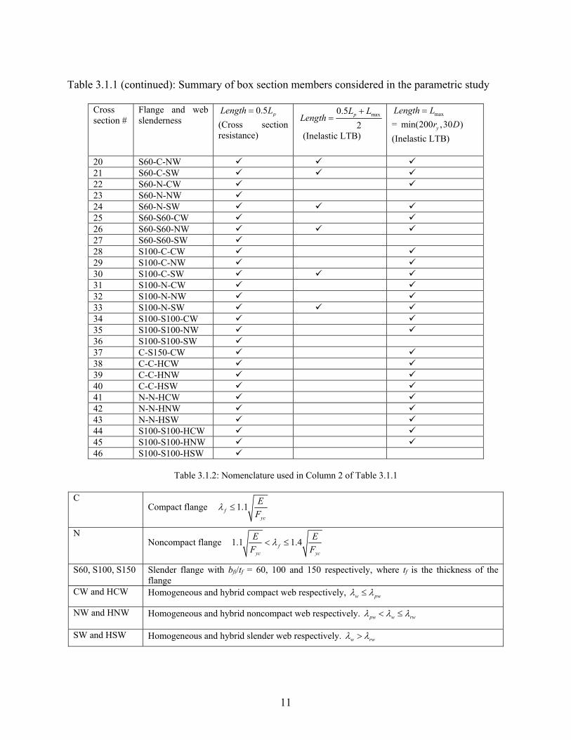
accurately predicts the elastic LTB moment. Table 3.1.1 provides a summary of the box section beams studied in the parametric study. Column 2 in Table 3.1.1 summarizes the slenderness of the different plates in the cross section. In Column 2, the first letter corresponds to the slenderness of the flange in flexural compression, the second letter corresponds to the slenderness of the flange in flexural tension and the third letter corresponds to the slenderness of the web. The nomenclature used in Column 2 of Table 3.1.1 is explained in Table 3.1.2. The dimensions of the different cross sections listed in Table 3.1.1 are provided in White et al. (2017). In addition to the cases in Table 3.1.1 the variation of the flexural resistance with change in length of the beam was studied for cross section# 6 (C-N-S) having an aspect ratio of 6.
Table 3.1.1: Summary of box section members considered in the parametric study
Cross section #
Flange and web slenderness
0.5 pLength L
(Cross section resistance)
max0.5
2
pL L
Length
(Inelastic LTB)
maxLength L
= min(200 ,30 )yr D
(Inelastic LTB)
1 C-C-CW 2 C-C-NW 3 C-C-SW 4 C-N-CW 5 C-N-NW 6 C-N-SW 7 C-S-CW 8 C-S-NW 9 C-S-SW 10 N-C-CW 11 N-C-NW 12 N-C-SW 13 N-N-CW 14 N-N-NW 15 N-N-SW 16 N-S-CW 17 N-S-NW 18 N-S-SW 19 S60-C-CW
11
Table 3.1.1 (continued): Summary of box section members considered in the parametric study
Cross section #
Flange and web slenderness
0.5 pLength L
(Cross section resistance)
max0.5
2
pL L
Length
(Inelastic LTB)
maxLength L
= min(200 ,30 )yr D
(Inelastic LTB)
20 S60-C-NW 21 S60-C-SW 22 S60-N-CW 23 S60-N-NW 24 S60-N-SW 25 S60-S60-CW 26 S60-S60-NW 27 S60-S60-SW 28 S100-C-CW 29 S100-C-NW 30 S100-C-SW 31 S100-N-CW 32 S100-N-NW 33 S100-N-SW 34 S100-S100-CW 35 S100-S100-NW 36 S100-S100-SW 37 C-S150-CW 38 C-C-HCW 39 C-C-HNW 40 C-C-HSW 41 N-N-HCW 42 N-N-HNW 43 N-N-HSW 44 S100-S100-HCW 45 S100-S100-HNW 46 S100-S100-HSW
Table 3.1.2: Nomenclature used in Column 2 of Table 3.1.1
C Compact flange 1.1 f
yc
E
F
N Noncompact flange 1.1 1.4 f
yc yc
E E
F F
S60, S100, S150 Slender flange with bfi/tf = 60, 100 and 150 respectively, where tf is the thickness of the flange
CW and HCW Homogeneous and hybrid compact web respectively, w pw
NW and HNW Homogeneous and hybrid noncompact web respectively. pw w rw
SW and HSW Homogeneous and hybrid slender web respectively. w rw

12
4. Finite element model Sections 4.1 through 4.7 provide details of the finite element model used for the parametric study. 4.1 General The general purpose finite element analysis software ABAQUS version 6.13, Simulia (2013), was used for the geometrically and materially nonlinear FE analyses for the parametric study. The four-node S4R shell element was used to model both the flanges and the web of the member. The S4R element is a general purpose large strain quadrilateral element which uses a single point numerical integration over its area combined with an algorithm for stabilization of the corresponding spurious zero-energy modes. A five point Simpson’s rule was applied for integration of the stresses through the thickness of the shell element. The Riks method was used to perform the incremental-iterative non-linear load-deflection analyses. Residual stresses were implemented via a user-defined FORTRAN subroutine. 4.2 Material model For homogeneous box section members the yield stress Fy was taken equal to 50 ksi and ultimate stress Fu was taken equal to 65 ksi for the flange as well as the web. For hybrid box section members the yield stress Fy and ultimate stress Fu were taken equal 50 ksi and 65 ksi respectively for the flange; and 70 ksi and 90 ksi respectively for the web. The material was modelled with a small tangent stiffness within the yield plateau region of E/1000 up to a strain-hardening strain of εst = 10εy, where εy is the yield strain of the material. Beyond this strain, a constant strain-hardening modulus of Est=E/50 was used up to the ultimate stress level. The material was modelled as perfectly plastic beyond this point. Figure 4.2.1 shows the stress strain curve used for steel with Fy = 50 ksi in the test simulation studies.
Figure 4.2.1: Steel stress-strain curve assumed in the structural analysis
Since the S4R element in ABAQUS is a large strain formulation, this element actually interprets the input stress versus plastic strain curve associated with Fig. 4.2.1 as the true stress versus log strain response. However, for the maximum strains commonly experienced at the limit load of the test simulations, the difference between the uniaxial true-stress versus log strain and

13
engineering stress versus engineering strain is small. The stress-strain curve shown in Fig. 4.2.1 is a reasonable representation of the true-stress true-strain response of structural steel for stresses up to the level of Fu. 4.3 Boundary conditions and loading The box section beam was flexurally and torsionally simply supported at the ends, and it was subjected to uniform bending. The beam multipoint constraint in Abaqus (Simulia 2013) was used for applying the end boundary conditions and loading. 4.4 Residual stresses A modified form of the ECCS (1976) residual stress model was used in the parametric study. This adopted residual stress model, shown in Fig. 4.4.1, accounts for the contributions from flame cutting and welding of the box section component plates. In Fig. 4.4.1, σc.lw, σc.tf, σc.rw and σc.bf, denote the compressive residual stresses in the left web, top flange, right web and bottom flange respectively. The model ensures that the compressive residual stress does not cause local buckling of the plate. A limit on the minimum compressive residual stress has been specified in the model and is equal to 0.2Fy or 0.1Fy depending on whether the critical buckling stress of the plate is greater than or less than 0.2Fy. The model captures important trends such as decrease in the compressive residual stress with increase in slenderness of the plate. This has also been confirmed by comparing the residual stress predictions from the model with residual stresses measured by other researchers. The residual stress model is explained in detail in White et al. (2017).
Figure 4.4.1: Residual stress pattern used in the parametric study
4.5 Geometric imperfections Both global (Fig. 4.5.1) and local imperfections (Fig. 4.5.2) were modelled. For global imperfection, the lateral displacement of the bottom flange was restrained and the top flange was given a sweep. The magnitude of the global imperfection was taken as 1/1000 of the beam length. For local imperfection, the transverse and lateral displacement of the corner nodes were restrained and an eigenvalue buckling analysis was performed with the member subjected to

14
axial load. The magnitude of the local imperfection of each plate was taken as 1/200 of the plate width.
Figure 4.5.1: Global imperfection Figure 4.5.2: Local imperfection 4.6 Validation of the FE model The finite element model was validated using the experimental tests from Pavlovcic et al. (2012). The experimental tests from Pavlovcic et al. (2012) were chosen for validating the FE model for two reasons: 1) The box section members tested by them were susceptible to combined global buckling and local buckling. 2) They had detailed measurements of initial imperfections, accidental load eccentricities and residual stresses. Table 4.6.1 shows a comparison between the results from the experiments and the test simulations. It can be seen that the test simulations give a good prediction of the results from the experimental tests.
Table 4.6.1: Validation of the FE model
Experiment Number
Description Eccentricity (mm)
Length (m)
Pmax_experiment (kN)
Pmax_simulation (kN)
max_
max_ exp
simulation
eriment
P
P
1 Column 0 3.65 706.5 699.4 0.99
2 Column 0 4.85 564 592.2 1.05
3 Beam-Column 20 3.65 566.5 572.2 1.01
4 Beam-Column 60 3.65 384.5 392.2 1.02
5 Beam-Column 200 3.65 206.5 201.5 0.98

15
4.7 Convergence study A convergence study was performed to select a mesh density which would provide accurate results with minimum computational effort. For the convergence study three different mesh sizes were considered as mentioned in Table 4.7.1. For all the three mesh sizes, the width of the element along the length of the member was taken equal to 1.1 times the width of the flange element. Both, geometric and material nonlinear analysis, and buckling analysis were performed for box section beams considering different lengths, flange plate slenderness, web plate slenderness and mesh sizes.
Table 4.7.1 Mesh sizes considered in the convergence study
Mesh number Number of elements across the flange width
Number of elements through the web depth
1 6 12
2 12 25
3 24 48
For geometric and material nonlinear analysis, the peak strength as well as the load deflection response considering different mesh sizes were compared. It was found that the mesh number 2 gave almost the same results as the much denser mesh number 3, and thus mesh number 2 was used for the main parametric study. 5. Results and discussion The following subsections discuss the results for the different homogeneous and hybrid box section members considered in the parametric study. It was found that the provisions discussed in Section 2 give a good prediction of the flexural resistance of the member with the mean, median and standard deviation of the ratio of the beam strength from test simulation to the strength predicted by the proposed equations being equal to 1.06, 1.06 and 0.07 respectively. 5.1 Homogeneous box section beams The following subsections discuss the results for plateau resistance and inelastic LTB resistance of homogeneous box section members. 5.1.1 Plateau resistance Figure. 5.1.1.1 shows a comparison of the member strength from test simulation with the strength predicted using the proposed provisions, current AASHTO (2015) Article 6.12.2.2.2 provisions and Eurocode provisions, for homogeneous box section members with length equal to 0.5Lp. The good performance of the proposed equations for cross sections 19 to 36, clearly shows that for cases with slender compression flange and non-compact web, the cross section resistance is larger than the yield moment of the effective cross section and going up to the plastic moment capacity of the effective cross section for box sections with compact webs. This point is reinforced by observing that for cases with slender flanges and compact webs (cross sections 19, 22, 25, 28, 31 and 34) the Eurocode provisions are overly conservative. As discussed earlier in the introduction, the Eurocode provisions are overly conservative for these cases because they classify a cross section based on the most unfavorable class of its compression parts and hence,

16
end up limiting the predicted cross section resistance of box sections with slender flanges and compact webs to yield moment of the effective cross section. Although box sections with slender flange and compact or noncompact web are more unusual, they may be encountered when considering biaxial bending, or when looking at the strength of a box girder, which will be composite in the final condition, with slender top flange and under construction loading. Good prediction of cross section resistance using the proposed provisions for extreme singly symmetric sections with larger compression flange (cross sections 7, 8, 9 and 37), clearly shows that for box section members the limit state of tension flange yielding is not required and the resistance is captured accurately by the general yielding strength up to the plastic moment of the effective cross-section. Also as discussed earlier in the introduction, the Eurocode gives conservative cross section resistance predictions for singly symmetric Class 3 and Class 4 box section members with larger compression flange, as it considers tension flange yielding by calculating the section modulus corresponding to the flange with maximum elastic stress. This can be seen by the conservative predictions using Eurocode for cross sections 8 and 9.
Figure 5.1.1.1: Comparison of the member strength from test simulation with the strength predicted using the
proposed provisions, current AASHTO (2015) Article 6.12.2.2.2 provisions and Eurocode provisions, for homogeneous box section members with length=0.5Lp
It can be seen from the results in Fig. 5.1.1.1, that for members with non-slender flanges and compact or non-compact webs, the cross section resistance is higher than the yield moment and up to the plastic moment of the gross cross section. Thus for cross sections 1, 2, 13 and 14, strength predicted using the AASHTO (2015) equations is conservative since the maximum flexural resistance predicted by the inelastic LTB equation in AASHTO (2015) is limited to the yield moment of the gross cross section. The inelastic LTB equation in AASHTO (2015) under-predicts the strength of box section members with slender webs because it does not account for web bend buckling. 5.1.2 Inelastic LTB resistance Figures 5.1.2.1 and 5.1.2.2 show the comparison of the member strength from test simulation with the strength predicted using the proposed provisions, current AASHTO (2015) Article 6.12.2.2.2 provisions and Eurocode provisions, for homogeneous box section members with

17
lengths equal to max0.5
2
pL L and maxL . It can be observed that the inelastic LTB resistance
calculated by considering a linear interpolation using Eq. 2 gives good predictions and performs much better than the current AASHTO (2015) Article 6.12.2.2.2 and Eurocode provisions.
Figure 5.1.2.1: Comparison of the member strength from test simulation with the strength predicted using the
proposed provisions, current AASHTO (2015) Article 6.12.2.2.2 provisions and Eurocode provisions, for
homogeneous box section members with length= max0.5
2
pL L
Figure 5.1.2.2: Comparison of the member strength from test simulation with the strength predicted using the
proposed provisions, current AASHTO (2015) Article 6.12.2.2.2 provisions and Eurocode provisions, for homogeneous box section members with length= max min(200 ,30 ) yL r D
18
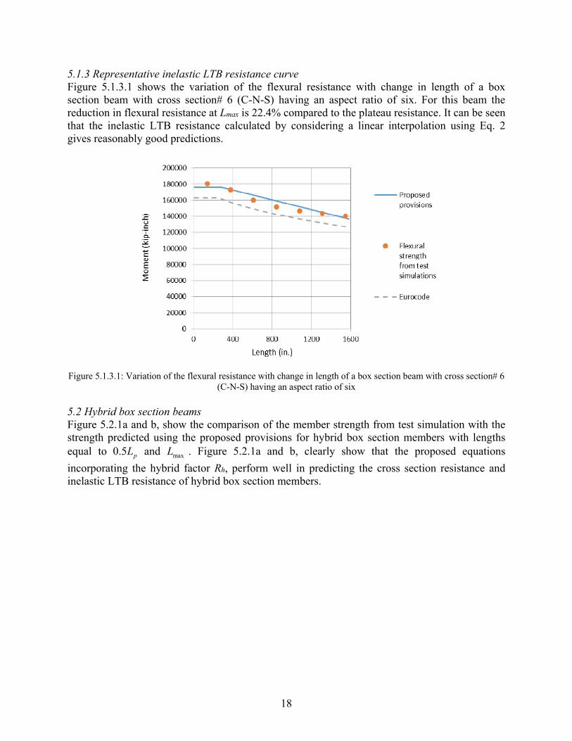
5.1.3 Representative inelastic LTB resistance curve Figure 5.1.3.1 shows the variation of the flexural resistance with change in length of a box section beam with cross section# 6 (C-N-S) having an aspect ratio of six. For this beam the reduction in flexural resistance at Lmax is 22.4% compared to the plateau resistance. It can be seen that the inelastic LTB resistance calculated by considering a linear interpolation using Eq. 2 gives reasonably good predictions.
Figure 5.1.3.1: Variation of the flexural resistance with change in length of a box section beam with cross section# 6
(C-N-S) having an aspect ratio of six 5.2 Hybrid box section beams Figure 5.2.1a and b, show the comparison of the member strength from test simulation with the strength predicted using the proposed provisions for hybrid box section members with lengths equal to 0.5 pL and maxL . Figure 5.2.1a and b, clearly show that the proposed equations
incorporating the hybrid factor Rh, perform well in predicting the cross section resistance and inelastic LTB resistance of hybrid box section members.

19
(a) (b)
Figure.5.2.1a and b: Comparison of the member strength from test simulation with the strength predicted using the proposed provisions for hybrid box section members with lengths 0.5Lp and maxL respectively
6. Summary and concluding remarks This paper explains the development of design provisions for any general singly or doubly symmetric non-composite non-longitudinally stiffened, homogeneous or hybrid welded box section beam, covering all ranges of web and flange plate slenderness and addressing all relevant limit states. The performance of the proposed provisions was evaluated via an extensive parametric study performed using test simulations and it was found that the proposed provisions give a good prediction of the flexural resistance and perform significantly better than the current AASHTO (2015) and Eurocode provisions. The proposed provisions allow the consideration of cross section resistance larger than yield moment and up to the plastic moment of the effective cross section, for box section beams with compact or noncompact webs. It was found from the test simulation studies that for box section beams the limit state of tension flange yielding is not required and the resistance is captured accurately by the general yielding strengths up to the plastic moment of the effective cross-section. 7. Acknowledgements This research is sponsored by the Federal Highway Administration and HDR Engineering Inc. Their financial support is gratefully acknowledged. The authors express special thanks to John Yadlosky (HDR Engineering Inc.), Anthony Ream (HDR Engineering Inc.), Charles King (COWI), Michael A. Grubb (M.A. Grubb & Associates, LLC) and Francesco Russo (Michael Baker International) and Brian Kozy of FHWA for their valuable input. The opinions, findings, and conclusions expressed in this paper are those of the writers and do not necessarily reflect the views of the above mentioned individuals and organizations. 8. References AASHTO (2015). “AASHTO LRFD Bridge Design Specifications.” Seventh Edition, American Association of State Highway and Transportation Officials, Washington DC.

20
AASHTO (2017). “AASHTO LRFD Bridge Design Specifications.” Eighth Edition (in press), American Association of State Highway and Transportation Officials, Washington DC. AISC (2016). “Specification for structural steel buildings.” American Institute of Steel Construction, Chicago, IL. CEN. (1992). “Eurocode 3: Design of Steel Structures, EN 1993-1-1: General Rules and Rules for Buildings.” European Committee for Standardization, Brussels, Belgium. CEN. (2005). “EN 1993-1-1. Eurocode 3: design of steel structures-Part 1-1: General rules and rules for buildings.” CEN. (2006). “EN 1993-1-5. Eurocode 3—design of steel structures-Part 1-5: Plated structural elements.” Clarin, M. (2007). “Plate Buckling Resistance. Patch Loading of Longitudinally Stiffened Webs and Local Buckling.” Doctoral thesis: 31, Lulea ˚ University of Technology, 2007, ISRNLTU-DT-07Ú31–SE. ECCS. (1976). “Manual on stability of steel structures.” 2nd ed. European Convention for Constructional Steelwork. Johansson, B. and Veljkovic, M. (2009). “Review of Plate Buckling Rules in EN 1993-1-5.” Steel Construction, 2(4), 228-234. Pavlovcic L, Froschmeier B, Kuhlmann U, Beg D. (2012). “Finite element simulation of slender thin-walled box columns by implementing real initial conditions.” Advances in Engineering Software, 44:63–74. Schillo, N., Taras, A., and Feldman, M. (2015). “Assessment of Safety Factor for Local Buckling,” presentation to Eurocode TC8 Bochum, Nov. 6. Peköz, T. (1969). "Torsional flexural buckling of thin-walled sections under eccentric load", Cornell Engineering Research Bulletin, September 1969. Simulia. (2013). “ABAQUS, Software and Analysis User’s Manual.” Version 6.13. White, D.W., A. Lokhande, C.M. King, M.A. Grubb, F. Russo, and A. Ream. (2017). “Resistance of General Noncomposite Steel Box Section Members,” Report to Federal Highway Administration, FHWA ID/IQ DTFH610-14-D-00049, August (to appear). White, D.W. and A. Lokhande. (2017). “A Review of Winter’s Equation and Various Plate Postbuckling Resistance Approximations,” Structural Engineering Mechanics and Materials Report No. 17-04, School of Civil and Environmental Engineering, Georgia Institute of Technology, Atlanta, GA. Young, W.C. (2002). “Roark’s Formulas for Stress & Strain.” 6th Edition, Mc-Graw-Hill Professional Publishing, New York, NY.