BEFORE THE DEPUTY CONTROLLER OF PATENTS...
80
1 BEFORE THE DEPUTY CONTROLLER OF PATENTS Patent office, Chennai THE PATENTS ACT, 1970 & THE PATENTS RULES, 2003 In the matter of an application for Patent bearing number 1120/CHE/2007 Titled ―Shock Absorber with helper spring‖ Filed by M/s TVS MOTOR COMPANY LIMITED---Applicant In the matter of Section 15 & In the matter of a representation by way of opposition to grant of patent filed U/S 25(1) by M/s BAJAJ AUTO LIMITED ----- Opponent 1 & In the matter of a representation by way of opposition to grant of Patent filed U/S 25(1) by M/s ENDURANCE TECHNOLOGIES LIMITED--- Opponent 2. Present during the hearing proceedings on the dates as mentioned against their names
Transcript of BEFORE THE DEPUTY CONTROLLER OF PATENTS...

1
BEFORE THE DEPUTY CONTROLLER OF PATENTS
Patent office, Chennai
THE PATENTS ACT, 1970
&
THE PATENTS RULES, 2003
In the matter of an application for Patent bearing number
1120/CHE/2007
Titled
―Shock Absorber with helper spring‖
Filed by
M/s TVS MOTOR COMPANY LIMITED---Applicant
In the matter of Section 15
&
In the matter of a representation by way of opposition to grant of patent filed U/S 25(1)
by M/s BAJAJ AUTO LIMITED ----- Opponent 1
&
In the matter of a representation by way of opposition to grant of Patent filed U/S 25(1)
by M/s ENDURANCE TECHNOLOGIES LIMITED--- Opponent 2.
Present during the hearing proceedings on the dates as mentioned against their names

2
(1) Mr. Damodar P Vaidya Of Lakshmi Kumaran & Sridharan, Patent agent for
Applicant. (25/04/2016 &10/05/2016)
(2) Mr. S.Jayaram, Member R&D,of TVS Motor Company Limited.( 25/04/2016
&10/05/2016)
(3) Ms. Brindha Mohan of Mohan Associates, Patent agent for the Opponent 1.(
10/05/2016)
(4) Mr. Milind V. Joshi of M/s Bajaj Auto Limited.( 10/05/2016)
(5) Mr. Rakesh Kumar of RK Dewan & Co, Patent agent for Opponent 2. Conducted
on 25/04/2016 &10/05/2016
(6) Mr.Soumya Prakash Patra,of M/s Endurance technologies limited. (25/04/2016 )
(7) Mr. Deep Prakash Gupt, Examiner of Patents and Designs. (25/04/2016
&10/05/2016)
1. An application for Patent filed by M/s TVS MOTOR COMPANY LTD with a
Provisional specification on 29/05/2007 and thereafter a complete specification was filed
on 21/05/2008. A request of Examination was filed on 27/01/2009 and First Examination
report (FER) was issued on 24/02/2014. A pregrant representation filed by way of
opposition was filed on 23/03/2012 by M/s BAJAJ AUTO LIMITED (Opponent 1) and
same representation along with the documents was forwarded to the applicant on
05/03/2014.Applicant filed their response on 05/06/2014. A pregrant representation filed
by way of opposition was filed on 05/09/2011 by M/s ENDURANCE TECHNOLGIES
LIMITED (Opponent 2) and the same representation along with the documents was
forwarded to the applicant on 05/03/2014 and applicant filed their response on
05/06/2014.
2. Summary of the invention
The present subject matter of the invention relates to a shock absorber for a vehicle and
in particular relates to a shock absorber with helper spring .According to at least one
embodiment of the present subject matter , the shock absorber includes a helper spring
122 that is slidably and concentrically disposed on a piston rod 108.The helper spring
122 is made up of polyurethane that has the property of absorbing and dissipating
energy efficiently, thereby increasing the passenger ride comfort and durability of the
shock absorber.

3
3. Back ground of the invention
Conventionally shock absorbers are provided with nonlinear rated springs to achieve
progressive stiffening. Progressive stiffening of a spring enables effective absorption of
road shocks over a wider range, thereby providing the ride comfort to the passengers.
The challenge associated with nonlinear rated springs is that the extent of non-linearity
achieved is limited primarily because of cost and manufacturing constraints. Further,
non-linearity achieved is not very progressive due to mechanical nature of the springs.
Another challenge associated is providing the shock absorber with only non-linear
springs is that absorption and dissipation of energy released during the dampening
process is not very effective and efficient. This primarily happens because of the time
lag of the damper in absorbing the energy and then releasing this absorbed energy to
the surroundings. This results in momentary discomfort to the occupants of the vehicle.
Aiding the shock absorber with a polyurethane helper spring though addresses this
challenge but it substantially increases the manufacturing cost of the shock absorber
.On the other hand , using a rubber helper spring does not reduce the time lag
substantially and hence it is not very effective in addressing the afore said challenge.
4. Objective of the invention:
Present invention proposes a method of increasing the performance and durability of
shock absorbers by ensuring the energy absorbed by the spring of the shock absorber
is efficiently and effectively dissipated to the surroundings and this leads to substantially
improvement in passenger ride comfort and durability of the shock absorber.
5. Solution for the problem
A shock absorber comprises of single rated coil spring , made up of a grade 2 wire ,
supports the weight of the vehicle and absorbs road shocks rapidly .The energy
absorbed by the single rated coil spring is then dissipated in the form of heat by
dampening fluid of the shock absorber. the said shock absorber also comprises of a
helper spring that is slidably and concentrically disposed on the piston rod .The helper
spring is made of polyurethane and has diameter that is substantially less than that of
the single rated coil spring, Polyurethane possesses the property of efficiently absorbing
and dissipating energy, thereby aiding single rated coil spring in energy dissipation.

4
6. Claims as originally filed
1. A shock absorber 100 for a vehicle, said shock absorber comprising:
a first fluid chamber 102 having a first end 104 and a second end 106;
a piston rod assembly comprising:
a piston rod 108 having a first end 110 and a second end 112;a piston 114 disposed
concentrically on said first end 110 of said piston rod 108 wherein said first end 110
of said piston rod 108 along with said piston 114 is capable of axially sliding through
said second end 106 of said first fluid chamber 102 towards said first end 104 of said
first fluid chamber 102;
a single rated coil spring 116 that opposes slidable movement of said piston rod
assembly in compression direction; said single rated coil spring 116 having an
upper end 118 and a lower end 120;
a helper spring 122 slidably and concentrically disposed on said second end112 of said
piston rod 108 wherein said helper spring 122 is having diameter substantially lesser
than said single rated coil spring 116;
characterized in that
said single rated coil spring 116 being made from Grade-2 wire and said helper spring
122 being made from polyurethane.
2. A twin tube shock absorber 200 for a vehicle, said shock absorber comprising:
a first fluid chamber 102 having a first end 104 and a second end 106;
a inner chamber 202 having a first end 204 and a second end 206; wherein said first
fluid chamber 102 is having a diameter substantially larger than said inner chamber
202, wherein said inner chamber 202 is disposed coaxially inside said first fluid
chamber 102 such that said first 104 and second 106 ends of said first fluid chamber
102 are disposed in close proximity to said first 204 and second 206 ends of said inner
chamber 202 respectively;
a piston rod assembly comprising:
a piston rod 108 having a first end 110 and a second end 112;

5
a piston 114 disposed concentrically on said first end 110 of said piston rod 108
wherein said first end 110 of said piston rod 108 along with said piston 114 is capable
of axially sliding through said second end 206 of said inner chamber 202 towards said
first end 204 of said inner chamber 202;
a single rated coil spring 116 that opposes slidable movement of said piston rod
assembly in compression direction; said single rated coil spring 116 having an upper
end 118 and a lower end 120;
a helper spring 122slidably and concentrically disposed on said second end 112 of said
piston rod 108 wherein said helper spring 122 is having diameter substantially lesser;
than said single rated coil spring 116;
characterized in that
said single rated coil spring 116 being made from Grade-2 wire and said helper spring
122 being made from polyurethane.
3. The shock absorber as claimed in claim I or 2, wherein said damping fluid is oil.
4. The shock absorber as claimed in claim I or 2, wherein said damping fluid is gas.
5. The shock absorber as claimed in claim I or 2, wherein said damping fluid is a
mixture of oil and gas.:
6. The shock absorber as claimed in claim I or 2, wherein said upper end 118 and lower
end 120 of said single rated coil spring 116 is having closed pitch coils.
7. Applicant has replied to the first examination report (FER) with amended claims on
18/02/2015
I. A shock absorber (100) for a vehicle, said shock absorber (I 00) comprising:
a first fluid chamber (102) having a first end (104) and a second end (106);a piston rod
assembly comprising:
a piston rod (I 08) having a first end (II 0) and a second end (112);
a piston (114) disposed concentrically on said first end (II 0) of said piston rod (I08)
wherein said first end (110) of said piston rod (I08) along with said piston (114) is

6
capable of axially sliding through said second end (106) of said first fluid chamber (102)
towards said first end (104) of said first fluid chamber (I02);
a single rated coil spring (116) that opposes slidable movement of said piston rod
assembly in compression direction, wherein said single rated coil spring (116) having an
upper end (118) and a lower end (120);
a helper spring (122) slidably and concentrically disposed on said second end (112) of
said piston rod (I 08), wherein said helper spring (122) is having diameter substantially
lesser than said single rated coil spring (116);
characterized in that
said single rated coil spring (116) being made from Grade-2 wire and said helper spring
(122) being made from polyurethane.
2. A twin tube shock absorber (200) for a vehicle, said shock absorber comprising: a
first fluid chamber (102) having a first end (104) and a second end (106);
a inner chamber (202) having a first end (204) and a second end (206); wherein said
first fluid chamber (102) is having a diameter substantially larger than said inner fluid
chamber (I02) such that said first (104) and second (106) ends of said first fluid
chamber (I02) are disposed in close proximity to said first (204) and second (206) ends
of said inner chamber (202) respectively;
a piston rod assembly comprising:
a piston rod (108) having a first end (II 0) and a second end (112);
a piston (114) disposed concentrically on said first end (110) of said piston rod(108)
wherein said first end (110) of said piston rod (108) along with said piston (114) is
capable of axially sliding through said second end (206) of said inner chamber (202)
towards said first end (204) of said inner chamber (202),
a single rated coil spring (116) that opposes slidable movement of said piston rod
assembly in compression direction; said single rated coil spring (116) having an upper
end (118) and a lower end (120);
a helper spring (122) slidably and concentrically disposed on said second end (112) of
said piston rod (108) wherein said helper spring (122) is having diameter substantially
lesser than said single rated coil spring (116);

7
characterized in that
said single rated coil spring (116) being made from Grade-2 wire and said helper spring
(122) being made from polyurethane.
3. The shock absorber as claimed in claim I or 2, wherein said damping fluid is oil.
4. The shock absorber as claimed in claim I or 2, wherein said damping fluid is gas.
5. The shock absorber as claimed in claim 1 or 2, wherein said damping fluid is a
mixture of oil and gas.
6. The shock absorber as claimed in claim I or 2, wherein said upper end (118) and
lower end (120) of said single rated coil spring (116) is having closed pitch coils.
8.This office has given due consideration to the reply given by the applicant and being
this office was not satisfied with the reply a hearing notice was issued to the applicant
on 02/02/2016 with the following objections and hearing was fixed on 02/03/2016 and
due to adjournments, hearing conducted on 25/04/2016
1. Claim(s) fall(s) within the scope of such clause (f) of section 3.
2. The alleged invention does not meet the requirement of section 2(1) (ja) of The
Patent Act, because the claimed subject matter does not constitute an Inventive step in
view of documents
D1: US3263983
D2: US5462140
D3: US5996978
DI teaches, a combined shock-absorber spring unit for a motor vehicle suspension (see
Division B7) comprises a double-acting telescopic shock-absorber 26 with a corrugated
rubber spring 72 surrounding the piston-rod 34 and surrounded by a coil-spring 56, the
arrangement being such that as the unit is compressed the coil spring and rubber spring
come into operation successively after an initial movement as rubber spring retainer 62
contacts stop 70 and then rubber spring 72 contacts retainer 62. The retainer 62 has
radial projections 68 which hold it on the coil spring. The spring 58 is held against the
lower spring seat by clips 58 retained by snap ring 60. The snap-ring 60 also holds the
two half-annular lower spring seat portions 50 in engagement with ridge 54 of the
reservoir tube 38.

8
D2 teaches, twin tube shock absorber has concentric inner and outer tubes connected
to the wheel of a vehicle. A piston in the inner tube is connected to the chassis of the
vehicle and divides the interior of the inner tube into upper and lower chambers. Fluid
passes between these chambers and an annular reservoir between the tubes for
absorbing shock in a conventional manner. An orifice is provided through the sidewall of
the lower portion of the inner tube and is surrounded by a lower sleeve, which normally
keeps the orifice closed. Upon upward acceleration of the tubes, the sleeve essentially
remains fixed in space. The relative movement between the sleeve and tubes aligns a
passage through the sleeve with the orifice and permits fluid to flow from the lower
chamber below the piston to the annular reservoir. This provides a softer shock
absorber when high upward acceleration is felt by the tubes of the shock absorber and
a stiffer shock absorber during times when there is no large upward acceleration. A
similar orifice and sleeve are provided at the upper end of the inner tube for permitting
fluid to flow from the upper chamber into the reservoir during rapid downward
acceleration of the tubes. The orifices are spaced apart from the ends of the inner tube
so that when the piston passes an orifice, the characteristics of the shock may change
from soft to stiff before the end of the stroke of the piston.
D3 comprises, A fluid pressure from an outside pressure source is supplied to the
pressurizing chamber to push down a damper piston via the free piston to thereby
forcibly contract the damper. In a second type, there is provided inside an inner tube a
cylinder which is slidably fit onto an outer surface of a rod, and a piston mounted on the
rod is inserted into the cylinder. A fluid pressure from the pressure source is supplied to
the pressurizing chamber inside the cylinder to push down the rod via the piston to
thereby forcibly contract the damper. In a third type, a rod is slidably inserted into a
partition wall in an intermediate portion of a damper main body of a mono-tube type of
damper. A free piston which is prevented by a stopper member from dropping out of
position downwards is slidably mounted onto an outer surface of a rod portion below the
partition wall. A fluid pressure from a pressure source is supplied to a pressurizing
chamber to be defined between the partition wall and the free piston. The rod is pushed
down via the free piston and the stopper member to thereby forcibly contract the
damper.
Hence a person skilled in the art will be motivated to combine the teachings of the cited
documents and come to a conclusion similar to present alleged invention.
The dependent claim [s] also do not provided any new feature with respect to the prior
art. Hence the present claim[s] are not allowable u/s 2(1)(ja) of the Patents Act.

9
3. Reference numerals shall be inserted inside the brackets in the claims.
4. FER of the application sent on 24/02/2014, the reply from the applicant received on
18/02/2015, applicant has produced amended claims along with the reply, but the
amended claims doesn‘t show any improvements or seems like earlier filed claims as
such. The inventive step in using single rated spring with spring aids or helper springs is
well known and doesn‘t show any improvements, also clearly falls under 3(f) of Indian
Patent act. With regard to objection 2 of FER, the applicant merely trying to combine
well known features like hydraulic dampers with helper springs made of PU (progressive
pressure/compression behavior) is well known in the prior art.Moreover no detailed
drawings are provided for structural constructional features of the claimed invention.
9. The learned agent appeared for the hearing u/s 14 hearing submitted their written
response on 26/05/2016.
The Learned agent for the applicant submitted that the invention as claimed discloses
the shock absorber to provide a comfortable ride to a passenger of a vehicle without
impacting the cost. The purpose is achieved by providing a combination of the
polyurethane helper spring and the single rated spring made of grade 2 steel wire,
working in close cooperation with each other to reduce the time lag between a release
of energy and dissipation of heat and further this provides a smooth ride over a larger
stroke /travel of the spring.
With regard to the objection Section 3(f), the learned agent for the applicant argued that
submitted that claims 1 to 6 is mere arrangement of known devices and the learned
agent submitted that while some individual components may be well known in the art
and may have been used for the purpose, the combination of such components acting
in tandem to provide comfort to a passenger of a two wheeler is not known in the art. In
fact such combination produces a significant technical advantage over the previously
known art.
A single rated coil spring of grade-2 wire and a polyurethane helper spring, working in
tandem with each other, provide an effective absorption and dissipation of energy
without any time lag. The polyurethane helper spring is activated by one end of a fluid
chamber after first part of travel of the single rated coil spring. Thereafter, the
polyurethane helper spring and the single rated coil spring work in tandem during the
latter part of the stroke to provide comfort to the rider by effectively dissipate the energy
without any time lag. Figure 4 of the specification clearly shows the enhanced
dissipation of energy by the single rated coil spring of grade-2 wire when used in
combination with the helper spring made of polyurethane. Therefore, the invention is not

10
mere arrangement or re- arrangement of known devices, but involves working of the
helper spring and the single rated coil spring in tandem with each other. Therefore, the
Applicant respectfully requested the Controller to withdraw the objection. Without
prejudice, the Applicant has amended the claim by way of explanation and by way of
disclaimer to highlight working of all the components in tandem with each other to
achieve the stated objective of the invention. The Applicant submits that the claims after
amendment are narrow and are fully supported in the specification, i.e., in the
drawings and description. The Applicant is amending the description by way of
explanation and the amendments are based on the drawings and as discussed with the
Controller. The Applicant is attaching the support chart.
With regard to the objection related to the inventive with in accordance with section
2(1)(ja) of the Patents Act in view of the documents D1: US3263983, D2: US5462140,
and D3: US5996978.
In response to this objection, the learned agent for the applicant had respectfully
explained that the cited references D1-D3 either alone or in combination, are not
relevant and also do not disclose or do not teach the invention. Therefore, these
documents cannot be considered relevant and disclosing or teaching the inventive
step of the present subject matter.
Concerning the inventive step of independent claim 1, the Applicant had submitted that
the following features as claimed in the invention are not disclosed in any cited
documents D1-D3:
a single rated coil spring (116) that opposes slidable movement of the piston rod
assembly in compression direction; the single rated coil spring (116) having an upper
end (118) and a lower end (120); wherein the single rated coil spring (116) is disposed
concentrically, and wherein the lower end (120) of the single rated coil spring (116) is
attached to the second end of the piston rod assembly and the upper end (118) of the
single rated coil spring is attached to the first end (104) of the first fluid chamber (102);
and
a helper spring (122) slidably and concentrically disposed on the second end (112) of
the piston rod (108) wherein the helper spring (122) is having diameter substantially
lesser than the single rated coil spring (116); wherein
the single rated coil spring (116) being made from Grade-2 wire and the helper spring
(122) being made from polyurethane, and wherein

11
the single rated coil spring (116) is compressed during the first part of the sliding of the
piston rod (108), and wherein
the second end (106) of the first fluid chamber (102) activates the helper spring (122) at
end of the first part of the sliding of the piston rod (108) so that the helper spring (122)
and the single rated coil spring (116) are compressed in tandem during the second part
of the sliding of the piston rod (108).‖
The learned agent for the applicant submitted that none of cited references D1-D3,
taken either alone or in combination, would enable a skilled person to arrive at the
invention. Furthermore, the invention also has a distinct advantage when considered in
light of cited references D1-D3. For example, the invention provides comfortable ride to
a passenger of a two wheeled vehicle, because the tandem working of the single rated
coil spring made of grade-2 wire and the helper spring made of polyurethane, enhances
the dampening property by dissipating the shock load without any time lag. Further this
advantage is achieved without impacting the cost, because the extra cost of the helper
spring made of polyurethane is compensated by lower cost of single rated spring made
of Grade-2 steel. The Applicant explained that a person skilled in the art would not
use Grade-2 steel wire for single rated coil spring, which is subjected to dynamic
load. For all these reasons, the Applicant, therefore, submitted that the subject matter
claimed in independent claim 1 involves an inventive step over cited references D1-D3.
Reference numerals have been incorporated in the claims.
10. A notice of P re grant Opposition hearing was issued to the applicants and
Opponents on 03/02/2016 and hearing was fixed on 03/03/2014.However based on the
requests of adjournments, hearing is refixed to 25/04/2016 and hearing for the applicant
and opponent 2 has conducted on the same day. Hearing for the applicant and
opponent 1 has conducted on 10/05/2016.
11. Learned agent for the applicant provided written submission to Section 14 hearing
along with the amended claims, description and drawings.
Amended claims filed on 26/05/2016 is reproduced here with and major portions which
are amended (added) underlined for clarity
1. A shock absorber (100) for a two-wheeled vehicle, the shock absorber (100)
comprising:
a first fluid chamber (102) having a first end (104) and a second end(106);

12
a piston rod assembly having a first end (124) and a second end(126), the piston rod
assembly comprising:
a piston rod (108) having a first end (110) and a second end(112), wherein the second
end (112) is attached to the second end (126) of the piston rod assembly; and
a piston (114) disposed at the first end (124) of the piston rod assembly, wherein the
piston (114) is concentrically mounted on the first end (110) of the piston rod (108), and
wherein the first end (110) of the piston rod (108) along with the piston (114) is capable
of axially sliding through the second end (106) of the first fluid chamber (102)
towards the first end (104) of the first fluid chamber (102), and wherein the sliding of the
piston rod (108) comprises a first part of the sliding and a second part of the sliding;
a single rated coil spring (116) that opposes slidable movement of the piston rod
assembly in compression direction, the single rated coil spring (116) having an upper
end (118) and a lower end (120), wherein the single rated coil spring (116) is disposed
concentrically, and wherein the lower end (120) of the single rated coil spring (116) is
attached to the second end (126) of the piston rod assembly and the upper end (118) of
the single rated coil spring is attached to the first end (104) of the first fluid chamber
(102); and
a helper spring (122) slidably and concentrically disposed on the second end (112) of
the piston rod (108), wherein the helper spring (122) is having diameter lesser than the
single rated coil spring (116); wherein
the single rated coil spring (116) being made from Grade-2 wire and the helper spring
(122) being made from polyurethane, and wherein the single rated coil spring (116) is
compressed during the first part of the sliding of the piston rod (108), and wherein the
second end (106) of the first fluid chamber (102) activates the helper spring (122) at end
of the first part of the sliding of the piston rod (108) so that the helper spring (122) and
the single rated coil spring (116) are compressed in tandem during the second part of
the sliding of the piston rod (108).
2. A twin tube shock absorber (200) for a two-wheeled vehicle, the shock absorber
(200) comprising:
a first fluid chamber (102) having a first end (104) and a second end (106);
a inner chamber (202) having a first end (204) and a second end (206); wherein the
first fluid chamber (102) is having a diameter larger than the inner chamber (202),
wherein the inner chamber (202) is disposed coaxially inside the first fluid chamber

13
(102) such that the first (104) and second (106) ends of the first fluid chamber (102) are
disposed in close proximity to the first (204) and second (206) ends of the inner
chamber (202) respectively;
a piston rod assembly having a first end (124) and a second end (126), the piston rod
assembly comprising:
a piston rod (108) having a first end (110) and a second end(112), wherein the second
end (112) is attached to the second end (126) of the piston rod assembly and;
a piston (114) disposed at the first end (124) of the piston rod assembly, wherein the
piston (114) is concentrically mounted on the first end (110) of the piston rod (108), and
wherein the first end (110) of the piston rod (108) along with the piston (114) is capable
of axially sliding through the second end (206) of the inner chamber (202) towards the
first end (204) of the inner chamber (202), and wherein the sliding of the piston rod
(108) comprises a first part of the sliding and a second part of the sliding;
a single rated coil spring (116) that opposes slidable movement of the piston rod
assembly in compression direction; the single rated coil spring (116) having an upper
end (118) and a lower end (120), wherein the single rated coil spring (116) is disposed
concentrically, and wherein the lower end (120) of the single rated coil spring (116) is
attached to the second end (126) of the piston rod assembly and the upper end (118) of
the single rated coil spring is attached to the first end (104) of the first fluid chamber
(102); and a helper spring (122) slidably and concentrically disposed on the second end
(112) of the piston rod (108) wherein the helper spring (122) is having diameter lesser
than the single rated coil spring (116); wherein the single rated coil spring (116) being
made from Grade-2 wire and the helper spring (122) being made from polyurethane,
and wherein the single rated coil spring (116) is compressed during the first part of the
sliding of the piston rod (108), and wherein the second end (106) of the first fluid
chamber (102) activates the helper spring (122) at end of the first part of the sliding of
the piston rod(108) so that the helper spring (122) and the single rated coil spring
(116)are compressed in tandem during the second part of the sliding of the piston rod
(108).
3. The shock absorber as claimed in claim 1 or 2, wherein the damping fluid is oil.
4. The shock absorber as claimed in claim 1 or 2, wherein the damping fluid is gas.
5. The shock absorber as claimed in claim 1 or 2, wherein the damping fluid is a mixture
of oil and gas.

14
6.The shock absorber as claimed in claim 1 or 2, wherein the upper end (118) and
lower end (120) of the single rated coil spring (116) is having closed.
In Para 0016 antitheft device has been deleted in the description
In para (0031) ] As it is apparent from FIG. 2 and FIG. 3, the piston rod assembly has a
first end 124 and a second end 126. The piston 114 is disposed at the first end 124 of
the piston rod assembly. The piston rod 108 along with the piston 114 axially slides
through the second end 106 of the first fluid chamber 102 towards the first end 104 of
the first fluid chamber 102. During a first part of the sliding of the piston rod 108, the
single rated coil spring 116 is compressed until the second end 106 of the fluid chamber
102 touches the helper spring 122. At the end of the first part of the sliding of the piston
rod 108, the helper spring 122 is activated by the first fluid chamber 102, as the second
end 106 of the first fluid chamber 102 comes in contact with the helper spring 122.
Further, during a second part of the sliding of the piston rod 108, the helper spring 122
and the single rated coil spring 116 are compressed in tandem.(has been added as
amendment in the description).
[0033] It is apparent from FIG. 4 that the curve 400 representing the energy
dissipated in the conventional non-linear coil spring used in combination with a Bump-
Stop is linear in nature while the curve 402 representing the energy dissipated by the
single rated coil spring 116 used in combination with the helper spring 122 is logarithmic
in nature. This shows that the tandem working of the single rated coil spring 116 and the
helper spring 122 provides the effective dissipation of heat (has been added in the
description).
Learned agent for the applicant provided statement under rule 14(2) of the Patent
amendment rules, 2016 for reason for amendment
1. Amendment: Page 5, Para [0016], Line 1 of the specification The term ―anti-theft
device‖ has been deleted. Instead, the word ―shock-absorber‖ has been added.
Reason for the amendment: The amendment is by way of correction of typographical
error.
2. Amendment: Page 8, Para [0031], Lines 17-27 of the specification The following
paragraph has been added by way of explanation of the FIG. 2 and FIG. 3. It is
submitted that no new matter is added.
―[0031] As it is apparent from FIG. 2 and FIG. 3, the piston rod assembly has a
first end 124 and a second end 126. The piston 114 is disposed at the first end 124 of
15
the piston rod assembly. The piston rod 108along with the piston 114 axially slides
through the second end 106 of the first fluid chamber 102 towards the first end 104 of
the first fluid chamber 102. During a first part of the sliding of the piston rod 108, the
single rated coil spring 116 is compressed until the second end 106 of the fluid chamber
102 touches the helper spring 122. At the end of the first part of the sliding of the piston
rod 108, the helper spring 122 is activated by the first fluid chamber 102, as the second
end 106 of the first fluid chamber 102 comes in contact with the helper spring 122.
Further, during a second part of the sliding of the piston rod 108, the helper spring 122
and the single rated coil spring 116 are compressed in tandem.‖
Reason for the amendment: Amendment is by way of explanation of the FIG. 2 and FIG.
3 to bring out more clarity.
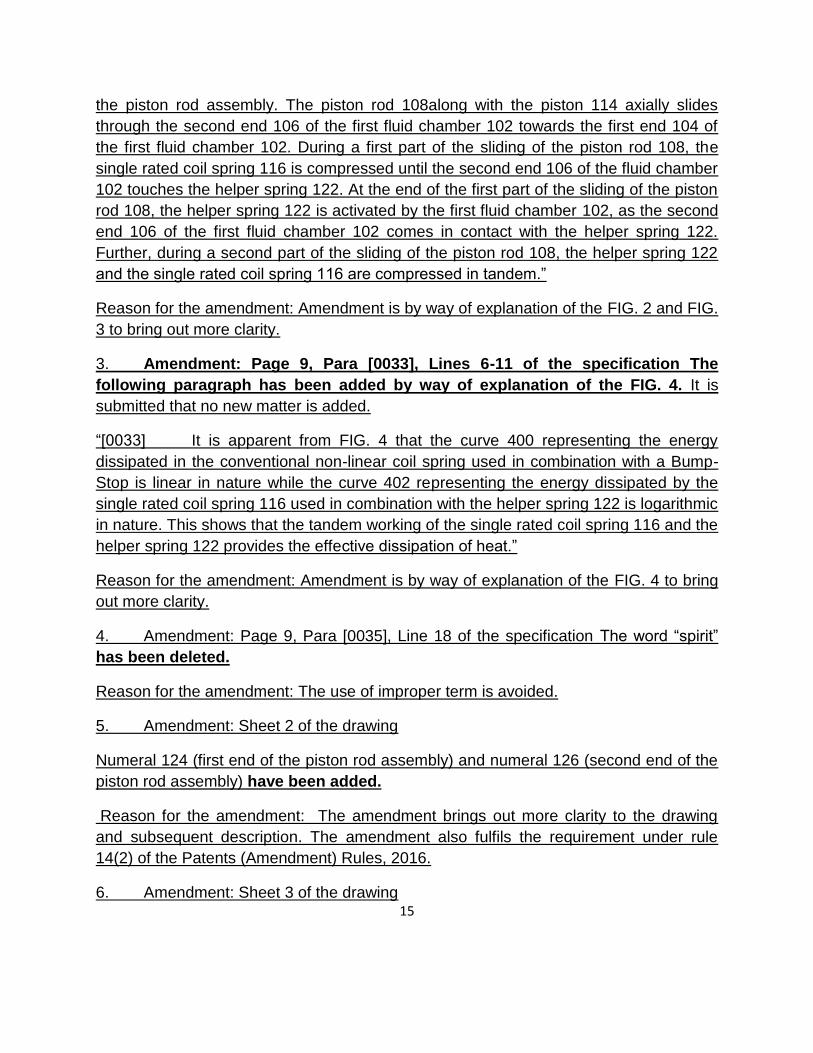
3. Amendment: Page 9, Para [0033], Lines 6-11 of the specification The
following paragraph has been added by way of explanation of the FIG. 4. It is
submitted that no new matter is added.
―[0033] It is apparent from FIG. 4 that the curve 400 representing the energy
dissipated in the conventional non-linear coil spring used in combination with a Bump-
Stop is linear in nature while the curve 402 representing the energy dissipated by the
single rated coil spring 116 used in combination with the helper spring 122 is logarithmic
in nature. This shows that the tandem working of the single rated coil spring 116 and the
helper spring 122 provides the effective dissipation of heat.‖
Reason for the amendment: Amendment is by way of explanation of the FIG. 4 to bring
out more clarity.
4. Amendment: Page 9, Para [0035], Line 18 of the specification The word ―spirit‖
has been deleted.
Reason for the amendment: The use of improper term is avoided.
5. Amendment: Sheet 2 of the drawing
Numeral 124 (first end of the piston rod assembly) and numeral 126 (second end of the
piston rod assembly) have been added.
Reason for the amendment: The amendment brings out more clarity to the drawing
and subsequent description. The amendment also fulfils the requirement under rule
14(2) of the Patents (Amendment) Rules, 2016.
6. Amendment: Sheet 3 of the drawing

16
Numeral 124 (first end of the piston rod assembly) and numeral 126 (second end of the
piston rod assembly) have been added.
Reason for the amendment: The amendment brings out more clarity to the drawing and
subsequent description. The amendment also fulfils the requirement under rule 14(2) of
the Patents (Amendment) Rules, 2016.
Claim Chart showing the support from the description
Amended Claim 1 Relevant portion of the description
A shock absorber (100) for a two-wheeled vehicle, the shock absorber (100) comprising:
Para [0001] - The subject matter described herein, in general, relates to a shock absorber
for a vehicle and in particular, relates to a
shock absorber with a helper spring.
a first fluid chamber (102) having a first end (104) and a second end (106);
Para [0019] - The mono-tube shock absorber 100 includes a first fluid chamber 102, having
a first end 104 and a second end 106 that
stores a damping fluid.
a piston rod assembly having a first end (124) and a second end (126), the piston rod
assembly comprising:
Para [0031] - As it is apparent from FIG. 2 and FIG. 3, the piston rod assembly has a first
end 124 and a second end 126.
a piston rod (108) having a first end (110) and a second end (112), wherein the second end
(112) is attached to the second end (126) of
the piston rod assembly; and
Para [0019] - The mono-tube shock absorber also includes a piston rod 108 having a first
end 110 and a second end 112, a piston 114
and valving components.
a piston (114) disposed at the first end of the piston rod assembly, wherein the piston (114)
is concentrically mounted on the first end
(110) of the piston rod (108), and wherein the
first end (110) of the piston rod (108) along
with the piston (114) is capable of axially
sliding through the second end (106) of the
first fluid chamber (102) towards the first end
(104) of the first fluid chamber (102), and
wherein the sliding of the piston rod (108)
comprises a first part of the sliding and a
second part of the sliding;
Para [0019] - The mono-tube shock absorber also includes a piston rod 108 having a first
end 110 and a second end 112, a piston 114
and valving components. The piston 114
along with the valving components is
disposed concentrically on the first end 110 of
piston rod 108. The piston rod 108, the piston
114 and the valving components form a
piston rod assembly that axially slides
through the second end 106 of the first fluid
chamber 102 towards the first end 104 of the
first fluid chamber 102.

17
a single rated coil spring (116) that opposes slidable movement of the piston rod assembly
in compression direction; the single rated coil
spring (116) having an upper end (118) and a
lower end (120), wherein the single rated coil
spring (116) is disposed concentrically, and
wherein the lower end (120) of the single
rated coil spring (116) is attached to the
second end (126) of the piston rod assembly
and the upper end (118) of the single rated
coil spring is attached to the first end (104) of
the first fluid chamber (102); and
Para [0020] - The single rated coil spring 116 opposes slidable movement of the piston rod
assembly in the compression direction and
also supports the weight of the vehicle. The
energy absorbed by the single rated coil
spring 116 is then dissipated in the form of
heat by the damping fluid of the shock
absorber 100. The single rated coil spring 116
has an upper end 118 and a lower end 120.
a helper spring (122) slidably and concentrically disposed on the second end
(112) of the piston rod (108), wherein the
Para [0021] - A helper spring 122 is slidably and concentrically disposed on the second end
112 of the piston rod 108. The helper spring
helper spring (122) is having diameter lesser than the single rated coil spring (116),
wherein
122 has a diameter substantially lesser than that of the single rated coil spring 116.
the single rated coil spring (116) being made from Grade-2 wire and the helper spring (122)
being made from polyurethane, and wherein
Para [0020] - Further, the single rated coil spring 116 is made up of a Grade-2 steel wire,
which is substantially cheaper than the
commonly used Grade-3 steel wires.
Para [0021] - The helper spring 122 is made
up of polyurethane material that has the
property of efficiently absorbing and
dissipating energy.
the single rated coil spring (116) is compressed during the first part of the sliding
of the piston rod (108), and wherein
Para [0031] - During a first part of the sliding of the piston rod 108, the single rated coil
spring 116 is compressed until the second end
106 of the fluid chamber 102 touches the
helper spring 122.
the second end (106) of the first fluid chamber (102) activates the helper spring
(122) at end of the first part of the sliding of
the piston rod (108) so that the helper spring
(122) and the single rated coil spring (116)
are compressed in tandem during the second
part of the sliding of the piston rod (108).
Para [0031] - At the end of the first part of the sliding of the piston rod 108, the helper spring
122 is activated by the first fluid chamber 102, as the second end 106 of the first fluid
chamber 102 comes in contact with the helper
spring 122. Further, during a second part of
the sliding of the piston rod 108, the helper
spring 122 and the single rated coil spring 116
are compressed in tandem.

18
12. I have to decide on two issues for further proceedings of this case
(a) Whether amendments carried out by the applicant in the description, claims and
drawings and submitted after all hearing proceedings falls within the scope of
Section 59(1) of the Patents Act?
(b) Whether Opponents were allowed to submit their arguments or a hearing
opportunity should be given to them regarding the amendments carried out in the
description, claims and drawings and submitted after hearing proceedings?
13.Analysis of the amendments carried out during the opposition proceedings.
Claim1 as on 18/02/2015 Amended claim1 filed on 25/05/2016
. A shock absorber (100) for a vehicle, said shock absorber (I 00) comprising: a first fluid chamber (102) having a first end (104) and a second end (106);a piston rod assembly comprising: a piston rod (I 08) having a first end (II 0) and a second end (112); a piston (114) disposed concentrically on said first end (II 0) of said piston rod (I08) wherein said first end (110) of said piston rod (I08) along with said piston (114) is capable of axially sliding through said second end (106) of said first fluid chamber (102) towards said first end (104) of said first fluid chamber (I02); a single rated coil spring (116) that opposes slidable movement of said piston rod assembly in compression direction, wherein said single rated coil spring (116) having an upper end (118) and a lower end (120); a helper spring (122) slidably and concentrically disposed on said second end (112) of said piston rod (I 08), wherein said helper spring (122) is having diameter substantially lesser than said single rated coil spring (116); characterized in that said single rated coil spring (116) being
A shock absorber (100) for a two-wheeled vehicle, the shock absorber (100) comprising: a first fluid chamber (102) having a first end (104) and a second end(106); a piston rod assembly having a first end (124) and a second end(126), the piston rod assembly comprising: a piston rod (108) having a first end (110) and a second end(112), wherein the second end (112) is attached to the second end (126) of the piston rod assembly; and a piston (114) disposed at the first end (124) of the piston rod assembly, wherein the piston (114) is concentrically mounted on the first end (110) of the piston rod (108), and wherein the first end (110) of the piston rod (108) along with the piston (114) is capable of axially sliding through the second end (106) of the first fluid chamber (102) towards the first end (104) of the first fluid chamber (102), and wherein the sliding of the piston rod (108) comprises a first part of the sliding and a second part of the sliding; a single rated coil spring (116) that opposes slidable movement of thepiston rod assembly in compression direction, the

19
made from Grade-2 wire and said helper spring (122) being made from polyurethane.
single rated coil spring (116) having an upper end (118) and a lower end (120), wherein the single rated coil spring (116) is disposed concentrically, and wherein the lower end (120) of the single rated coil spring (116) is attached to the second end (126) of the piston rod assembly and the upper end (118) of the single rated coil spring is attached to the first end (104) of the first fluid chamber (102); and a helper spring (122) slidably and concentrically disposed on the second end (112) of the piston rod (108), wherein the helper spring (122) is having diameter lesser than the single rated coil spring (116); wherein the single rated coil spring (116) being made from Grade-2 wire and the helper spring (122) being made from polyurethane, and wherein the single rated coil spring (116) is compressed during the first part of the sliding of the piston rod (108), and whereinthe second end (106) of the first fluid chamber (102) activates the helper spring (122) at end of the first part of the sliding of the piston rod (108) so that the helper spring (122) and the single rated coil spring (116) are compressed in tandem during the second part of the sliding of the piston rod (108).
14. In view of the amendments,
Following four conditions to be satisfied for passing amendment‘s in accordance with
Section 59(1) of the Patents Act.
(1).The amendment can only be by the way of disclaimer, correction and
explanation.

20
(2).No amendment shall be allowed except for this purpose of incorporation of
actual fact.
(3).Amendment, the effect of which would be that of the specification as amended
would claim or describe the matter not in substance disclosed or shown in the
specification before the amendment, shall not be allowed.
(4).Amendment, the effect of which would be that any claim as amended would
not fall wholly within the scope of a claim of the specification before the
amendment, shall not be allowed.
15. I have referred the following case laws
1.OA/4/2009/PT/CH (ORDER NO:189/2012) of The Hon’ble IPAB: Amended claims are beyond the scope of the
claims as originally filed specification in view of the additional elements and amended claims were not allowed.
2.ORA/17/2009/PT/CH and ORA/31/2009/PT/CH (ORDER NO:140/2012 The Hon’ble IPAB: “We are convinced
that amendments carried out duing the prosecution of the application in the specification , drawings and claims
extend beyond the scope of disclosed matter and claims which is particularly prohibited by Section 59”.
a. In Order no. 140/2012, the Intellectual Property Appellate Board has stated:
In Bonzel (T.) and Anr.v.Intervention Limited and Anr.(No:3) (1991) RPC 553 at page
no: 574 the well-known test for deciding if new matter has been added has been set out
clearly .According to this task of the court is threshold
(1) To ascertain through the eyes of the skilled addressee what is disclosed , both
explicitly and implicitly in the application.
(2) To do same in respect of the Patent as granted.
(3) To compare the two disclosures and decide whether any subject matter relevant to
the invention has been added whether by deletion or addition. The comparison is strict
in the sense that subject matter will be added unless such matter is clearly and un
ambiguously disclosed in the application either explicitly or implicitly.
Further the court of Appeal in A.C. Edwards Ltd.V.Acme Signs & Displays Ltd (1992)
RPC 131 quoted from the decision of the EPO technical board of Appeals in Thomson-
CST (T151/84) (1998) E.P.O.R 29 as follows
3. In order to determine whether or not the modification made to a claim extends the
subject matter of the patent application beyond the contents of the application as filed, it

21
is necessary to find out whether the resulting modification to the contents of the
application (Whether by addition, modification or withdrawal) is such that information
presented to the skilled man is not derived directly and un ambiguously from that which
the application contained previously, even taking account of the elements which are
implicit to the skilled man (Guidelines For Examination at the EPO,C-V1,5.4).In other
words , it is necessary to find out whether the new claim presented is supported by the
original description.
3.1.In the case in point , the important thing is therefore not that a logical analysis of the
text be carried out in order to determine whether or not the initial intention of the
applicants was to limit the protection claimed to a particular combination of
characteristics described and represented, but rather that it to be discovered whether
the skilled man reading the patent application as filed would consider that the
characteristics under discussion, namely the presence of permanent magnets, is or is
not a characteristic which is dispensable to the operation of the device described in the
application.
As Whitford J observed in Polymer corporation patent (1972) RPC 39 at 45
―Explanation means making plain or making clear‖ I t can make the ambiguous clear ,
but no the insufficient sufficient. It is therefore a question of the fact in each case as to
the information contained in the original specification and it requires to be further
explained. The essence of the explanatory amendments are in that they often make
explicit what is clearly implicit to a fair minded and properly instructed person reading
the document carefully as a whole, but might be so clear in the more casual or biased
reader. They are made for the avoidance of the doubt, even an unreasonable doubt.
The amendments shall be in a sense of the kind which otherwise necessary‖.
31. if we see the purpose of the amendments under section 57(6) and the limitation
imposed on the amendments under section 59 we find that it is necessary , in our view
to take consideration the following;
1. Does Section 57(6) permit an applicant to file an application which is
defective in it’s description of the invention inorder that he may subsequently
make good that defect by providing additional further descriptive material?
2. Are all routes for amending defects, subject to Section 59?

22
3. Does even refining of description in the specification by way of explanation be
held to be an amendment to cure the deficiencies that are not permissible under section
59?
In considering the whole question of discretion in respect of amendments under section
57(6) in present case it is also necessary , in our view to take in to consideration the
nature and extent of amendment, when they are primarily for explanation and it is in
public interest to allow them, In absence of very compelling reason to the contrary.
However these amendments in any case will not be stretched beyond the limitations
imposed by section 59.The purpose of Section 57(6) is not to permit an applicant to
file an application which is defective in it’s description of the invention inorder he
may subsequently make good that defect by providing additional further
descriptive material.
When we apply the above tests relating to the amendment to the present case we find
all the matter which was added during the prosecution of application was not merely
explanatory as additional elements such as ----- were added. These elements were not
disclosed in the specification even implicitly. Additional drawings relating to additional
matter were also filed to support the claims for these elements. We find that effect of the
added matter in the specification and claims is such that it described the matter not in
substance disclosed or shown in the specification before the amendment. Further
amended claims 1-20 do not fall wholly within the scope of the claims 1-4 as originally
filed. We are convinced that amendments carried out during the prosecution of
the application in the specification, drawings and claims extend the scope of
disclosed matter and claims, which is particularly prohibited by Section 59. The
applicants therefore succeed in proving that new matter has been added by the
Respondent 1 during the prosecution of the application which was allowed by
Respondent 2. The Respondent 2 ought to have sought for explanation from the
Respondent 1. Respondent 2 ought to have applied his discretion more cautiously and
judiciously under section 57(6), especially when there are large scale amendments as in
the present case. Therefore, we are constrained to set aside the amendments
allowed during prosecution of the application.
b. In Order no. 189/2012, the Intellectual Property Appellate Board has stated:
65. The counsel relied on the following Judgments/Case Laws
(a) Smith Kline & French Laboratories Limited vs. Evans Medical Limited - 1989 (1)
Fleet Street Reports 561
23
The principles in respect of law on amendment of specification/claims have been
enunciated in the above mentioned case in para 2 at page 569 as under:
"The discretion as to whether or not to allow amendment is a wide one and the cases
illustrate some principles which are applicable to the present case. First, the onus to
establish that amendment should be allowed is upon the patentee and full disclosure
must be made of all relevant matters. If there is a failure to disclose all the relevant
matters, amendment will be refused. Secondly, amendment will be allowed provided the
amendments are permitted under the Act and no circumstances arise which would lead
the court to refuse the amendment. Thirdly, it is in the public interest that amendment is
sought promptly. Thus in cases where a patentee delays for an unreasonable period
before seeking amendment, it will not be allowed unless the patentee shows reasonable
grounds for his delay. Such includes cases where a patentee believed that amendment
was not necessary and had reasonable grounds for that belief. Fourthly, a patentee who
seeks to obtain an unfair advantage from a patent, which he knows or should have
known should be amended, will not be allowed to amend. Such a case is where a
patentee threatens an infringer with his unamended patent after he knows or should
have known of the need to amend. Fifthly, the court is concerned with the conduct of the
patentee and not with the merit of the invention. "
b. Bristol-Myers Co. (Johnson & Hardcastle's) [1974] RPC 389
------ The reasoning, ratios and precedents cited in this case to arrive at the said
conclusions clearly suggest that the amendments sought in the present case are liable
to be rejected. Few of such reasoning/ratios are reproduced as under:
At page 400, para 2 it is observed as under:
"Lord MacDermott quotes from the speech of Lord Westbury in the Ralston case and
refers in particular to a passage where Lord Westbury said: (see Lord MacDermott's
speech, page 66, line 41):
"But it was never intended that you should convert a bad specification in the sense of its
containing no description of any useful invention at all into a good specification by
adding words that would convert what has been properly called in the court below a
barren and unprofitable generality into a specific and definite and practical description. It
is quite clear that, if that could be done. you would have an opportunity of introducing
into a bad patent which contained no useful invention whatever. some discovery that
might be developed by further experiment, and which was altogether unknown at the
time of the original specification, and not at all included in the description contained in it

24
", and later ―...the statute never contemplated that the patentee should have the power.
under the form of a disclaimer, of making material additions to the original specification,
so as bv the aid of the corrected form of words. and the additions so made. to introduce
into the specification an accurate and perfect description of an invention which you seek
for in vain in the original specification."
At the same page, it was further observed as under:
"He also cited a passage from a decision of Mr. Justice Luxmoore in Eveno's Patent
(1932) 2 Ch. 167, where Luxmoore, J. said:
"Can it be said that any amendment which in fact results in a narrower claim than that
originally put forward is by way of disclaimer? In my judgment, it is necessary to
consider not whether the amended claim is narrower or more restricted than the original
claim, but whether it covers something not claimed or suggested as constituting the
original invention, or part of the original invention. If it does. then it seems to me that the
amendment can only properly be described as covering a fresh claim, and it would be
an abuse of language to say that such a claim arose owing to amendment by way of
disclaimer.‖
In para 4 at page 402, it is held as under:
"It is plain that the present case differs in certain important respects from AMP Inc. v.
Hellerman Ltd. By this amendment the applicants are not seeking to limit a construction
by adding a further feature. They are seeking to discard one form of starting material,
and that not because they want to give it up because they want voluntarily to relinquish
this part of a properly claimed monopoly, but because they must exclude the hydrated
salt if " their patent is to stand valid. I do not think this is truly disclaimer.
73. Respondent 1 disallowed these amendments stating that the amendments in claims
are ‗not fairly supported by description and requires addition of new subject matter‘. We
are convinced that the amendment of claims is not permissible but for the different
reason that the amended claims would not fall wholly within the scope of a claim of the
specification before the amendment as required under section 59. We however affirm
his decision for the reason stated above.
16. Applicants have carried out two types of amendments
(1) Voluntary amendment
(2) Amendment in order to meet office objections.

25
17.On my observation amendment carried out in the page no:5, Para (0016), line of the
specification ―the term antitheft device ―has been deleted and shock absorber has been
added and reason provided by the applicant is the amendment is by a way of correction
of typographical error. Neither form 13 nor request for correction of clerical error has
been submitted along with the prescribed fees being it is considered as voluntary
amendment. Further In page no: 9, Para (0035), Line 18 of the specification the word
spirit has been deleted being it was use of improper term which is deleted by the
applicant voluntarily and no prescribed form along with the fees has been filed.
18. Amendment carried out in the page 8, para (0031), lines 17-27 of the specification
and the following paragraph has been added by the way of explanation of Fig: 2 and Fig
:3.Further description has been added in para (0033) by way of explanation of Fig
:4.And two reference numerals (124 & 126) has been added in sheet 2 and sheet 3 of
the drawings. It is very clear that additional technical features have been incorporated in
the description which is substantially contributing to the invention and further these
additional features are incorporated in the claim1 and claim 2 as well which makes
claims elaborate. It is clearly ordered by the Hon‘ble IPAB that the purpose of the
Section 57(6) is not to permit an applicant to file an application which is defective in its
description of the invention in order; he may subsequently make good that defect by
providing additional further descriptive material.
19. I carefully considered the arguments put forward by the learned agent for the
applicant and based on the decisions issued by the Hon‘ble IPAB and my own analysis,
I have concluded that the amendments carried out in the description, claims and
drawings and submitted along with the written submission after all hearing proceedings
goes beyond the scope of section 59 of the Patents Act. In view of the reasons stated,
this office is not in position to allow these amendments carried out and submitted after
all hearing proceedings.
20. Learned agents for applicants submitted their written response on 1/06/2016 and
they have also filed an expert affidavit, for the hearing proceedings happened with
Opponent 2 on 25/04/2016. Learned agents for Opponent 2 have filed their written
response on 13/05/2016. Learned agents for applicant filed their written response on
03/06/2016 for the hearing proceedings happened with Opponent 1 on 10/05/2016 and
learned agents for the Opponent 1 has filed their written response on
4/06/2016.However the learned agent for opponent 1 requested time for filing expert
affidavit based on the natural justice principle and based on the decisions taken by the
Hon‘ble Madras High court and the Hon‘ble IPAB, It is decided to take that expert
affidavit from the opponent 1 along with a Petition U/R 137.
26
Extracts of High Court decision is reproduced here with for clarity
Hon’ble High Court of Madras in the case Novartis AG Vs. Union of India and
others ( W.P.No. 15736 of 2015)in the matter against the decision of Hon’ble IPAB
(ORA/21/2013/PT/CH) for reception of additional documents and raising additional
grounds. The Hon‘ble High court ordered that ― We have no hesitation to hold that the
appellate Board is vested with powers to regulate its own procedure as it is vested with
same powers of a civil court under code of civil procedure, More particularly for the
purpose of receiving evidence. Thus the Appellate Board was fully justified in
entertaining the Miscellaneous Petition filed by the second respondent. In the Light of
the above --- discussion, the order impugned passed by the IPAB was held and was not
interfered. Accordingly, the writ petition failed and was dismissed.
This office has noted that request from both the opponents that an opportunity may be
provided in case this office is considering the amendments put forward by the applicant
after the hearing proceedings, being this office have decided not to allow the
amendments carried out by the applicant that requests are not considered. So I proceed
further with the claims on 18/02/2015 on which hearing proceedings are happened
between two opponents and the applicant and for better clarity claims are reproduced
herewith.
I. A shock absorber (100) for a vehicle, said shock absorber (I 00) comprising:
a first fluid chamber (102) having a first end (104) and a second end (106);a piston rod
assembly comprising:
a piston rod (I 08) having a first end (II 0) and a second end (112);
a piston (114) disposed concentrically on said first end (II 0) of said piston rod (I08)
wherein said first end (110) of said piston rod (I08) along with said piston (114) is
capable of axially sliding through said second end (106) of said first fluid chamber (102)
towards said first end (104) of said first fluid chamber (I02);
a single rated coil spring (116) that opposes slidable movement of said piston rod
assembly in compression direction, wherein said single rated coil spring (116) having an
upper end (118) and a lower end (120);
a helper spring (122) slidably and concentrically disposed on said second end (112) of
said piston rod (I 08), wherein said helper spring (122) is having diameter substantially
lesser than said single rated coil spring (116);
27
characterized in that
said single rated coil spring (116) being made from Grade-2 wire and said helper spring
(122) being made from polyurethane.
2. A twin tube shock absorber (200) for a vehicle, said shock absorber comprising: a
first fluid chamber (102) having a first end (104) and a second end (106);
a inner chamber (202) having a first end (204) and a second end (206); wherein said
first fluid chamber (102) is having a diameter substantially larger than said inner fluid
chamber (I02) such that said first (104) and second (106) ends of said first fluid
chamber (I02) are disposed in close proximity to said first (204) and second (206) ends
of said inner chamber (202) respectively;
a piston rod assembly comprising:
a piston rod (108) having a first end (II 0) and a second end (112);
a piston (114) disposed concentrically on said first end (110) of said piston rod(108)
wherein said first end (110) of said piston rod (108) along with said piston (114) is
capable of axially sliding through said second end (206) of said inner chamber (202)
towards said first end (204) of said inner chamber (202),
a single rated coil spring (116) that opposes slidable movement of said piston rod
assembly in compression direction; said single rated coil spring (116) having an upper
end (118) and a lower end (120);
a helper spring (122) slidably and concentrically disposed on said second end (112) of
said piston rod (108) wherein said helper spring (122) is having diameter substantially
lesser than said single rated coil spring (116);
characterized in that
said single rated coil spring (116) being made from Grade-2 wire and said helper spring
(122) being made from polyurethane.
3. The shock absorber as claimed in claim I or 2, wherein said damping fluid is oil.
4. The shock absorber as claimed in claim I or 2, wherein said damping fluid is gas.
5. The shock absorber as claimed in claim 1 or 2, wherein said damping fluid is a
mixture of oil and gas.

28
6. The shock absorber as claimed in claim I or 2, wherein said upper end (118) and
lower end (120) of said single rated coil spring (116) is having closed pitch coils.
24. Opponents submitted following documents for proving lack of novelty and
inventive step.
1. DE 10034563 A1(herein after referred as D1) relates to a spring element containing
an insert (1) consisting of a compact material that is more rigid than the material that the
spring element consists of, a part (2) that functions as a helper spring and a part (3) that
functions as a spring pad. The spring elements produced from polyurethane elastomers
are used in automobiles addition products, for example within the chassis, example, on
the basis of elastic plastic materials, such as rubber or elastomers based on
polyisocyanate poly, such as polyurethanes and / or polyureas, uses, and are well
known. They are particularly used in motor vehicles as overload springs, impact
dampers or stops.
2.DE 10337175 (herein after referred as D2) relaters to a spring construction, in
particular in automotive suspensions, comprising spiral spring , at the end thereof of a
spring seat is positioned as well as a preferably cylindrical , preferably hollow auxiliary
spring , preferably on the basis of cellular polyisocyanate poly addition products ,
particularly preferably based on the cellular polyurethane elastomers preferably having
a density according to DIN53420 from DIN 200 TO 1100. In addition , the invention
relates to automobiles, that vehicles of all kinds eg. Passenger cars, lorries or buses ,
as well as motor cycles and bicycles, but preferably motor vehicles comprising spring
elements according to the invention and/or spring structures, particularly in the chassis.
Made from polyurethane elastomer suspension elements are used in automobiles , for
example within the chassis and are generally known. Typical spring designs are
constructed such that on the piston rod of the shock absorber from an additional spring
polyurethane elastomers is fixed.In addition, there is usually a helical spring, which is
fixed on a spring pad.
3.DE10344102 (herein after referred as D3) relates to a spring carrier with an auxiliary
spring according----- the additional spring often made of cellular elastomer.
4.DE20309425 (U1) (here in after referred as D4) relates a spring based on a
polyisocynate polycondensation product, preferably polyurethane , and is 105-115mm
high and of diameter 53-56 mm.

29
5.DE20311243 ( herein after referred as D5) relates a helper spring is based on a
polyisocyanate condensation product, preferably polyurethane, and is 78-82 mm high
and of diameter 59-63 mm. The end is in the form of a lip and the element has a hollow
internal diameter of 20-24 mm. Preferably the outside of the spring has grooves and
protuberances with a distance between protuberances of 5-15 mm.product,.
6.US3263983 (herein after referred as D6) discloses a shock absorber and auxiliary
spring unit. In FIGURE 4 discloses the various components of the unit 24 when in a full
jounce position. Under these conditions, the retainer 62 is in engagement with the stop
member 70 causing the spring 56 to carry a large portion of the sprung vehicle weight.
By rigidly securing the lower end of the coil spring 56 to the shock absorber tube 38,
there is less tendency for it to buckle as compared with designs wherein the lower end
of the coil spring is merely seated on a support member. A rubber corrugated spring 72
may also be provided. A spring of this type is shown in Patent No. 168,845. This spring
comes into operation only during extreme jounce deflection such as shown in FIGURE
4. That figure discloses the manner in which the spring 72 is distorted. It has a sliding fit
on the rod 34.
7.US4486028A (herein after referred as Y1). discloses a front wheel support structure
for an automobile comprises a first support fixed to a body, a second support disposed
beneath and spaced at the inner portion thereof from the first support, contacting a
bound stopper at the underside of the inner peripheral portion and secured fixedly to the
first support at the outer peripheral portion, a mount rubber disposed between both
supports, a connecting member secured fixedly to the mount rubber and mounted on
the upper portion of a piston rod of a shock absorber and a bearing seat disposed at the
underside of the second support and contacting a spring seat for receiving the upper
end of a coil spring. In use of the support structure, force from the piston rod is
transmitted from the mount rubber through the first support to the body, force from the
bound stopper is transmitted from the second support through the first support to the
body and force from the coil spring is transmitted from the spring seat to the bearing
seat and further through the second and first supports to the body respectively.
8. US4477061 (herein after referred as Y2) discloses a MacPherson strut type
suspension including a shock absorber operatively disposed between vehicle wheels
and a vehicle body of a motor vehicle, the shock absorber having a piston rod; a coil
spring disposed in association with the shock absorber to elastically support the vehicle
body; a core member secured to an end of the piston rod of the shock absorber; an
insulator rubber securely connected between the core member and the vehicle body;
and a stop device for restricting the movement of the core member in the axial direction

30
of the piston rod of the shock absorber when the axial movement of the piston rod
exceeds a predetermined distance, thereby effectively damping high and low frequency
vibrations applied to the suspension while prolonging the life of the insulator rubber.
9. US4175770 (herein after referred as Y3) relates to suspension struts for motor
vehicles, utilising a telescopic damper.
10. US4438660 (herein after referred as Y4) relates to an operator-movable control
lever assembly with a single lever having both friction-held and spring-centered
operational modes .
11.US 4042259 (herein after referred as Y5) relates to suspension strut assemblies for
wheel suspensions of motor vehicles.
12.US3263983 (herein after referred as Y6) relates to A vehicle suspension system
having sprung and unsprung parts, a suspension spring interposed between said parts
and constructed for resiliently supporting said sprung parts on said unsprung parts, a
direct acting telescopic shock absorber interposed between said parts, said shock
absorber having a body portion connected to one of said parts and a piston rod portion
connected to the other of said parts, a spring seat secured to said body portion, a coil
spring disposed concentrically about said body portion and having one end secured to
said spring seat, a cupshaped rubber retaining member connected to the other end of
said coil spring and slidably receiving said piston rod portion, a rubber'spring
surrounding said piston rod portion and situated within said coil spring between said
retaining member and said body portion, a stop member secured to the end of said
piston rod portion, said stop member being spaced apart from said retaining member
when said shock absorber is in an extended rebound position but engaging said
retaining member when in a jounce position.
13 .US 2003137091 (herein after referred as Y7)concerns a suspension stop device, for
a motor vehicle driving wheels, comprising a filtering block, consisting of an upper
housing fixed relative to the vehicle body and co-operating with a lower housing mobile
in rotation about a shock absorber rod and supporting a suspension spring, and a ball
bearing. Said upper (21) and lower (23) housings are made of thermoplastic material
and have opposite surfaces hollowed out in a circle, about the rotation axis (d) of the
shock absorber rod (24), to receive a raceway for the ball bearing (22). The upper
housing (21) further incorporates an impact stop (42) moulded around the leading stop
(41) of the shock absorbing device, and the thermoplastic structure of the upper housing
(21)is reinforced by a ring (45) made of overmoulded elastomer.

31
14. US6227527 (Herein after referred as Y8) relates to a pneumatic suspension system
forming a McPherson strut.
15. US5676355 (herein after referred as Y9) relates to a suspension system which is
applicable to automobiles.
16. US 5257730 (herein after referred as Y10) relates to a bound stopper for use in a
suspension of a motor vehicle, which is fitted on a piston rod of a shock absorber of the
suspension, for elastically limiting a stroke of the piston rod by abutting contact with a
cylinder of the shock absorber. The bound stopper includes a cylindrical main elastic
body formed of a rubber material and having an engaging portion at one axial end on
the side of the cylinder of the shock absorber, and a cylindrical auxiliary elastic body
formed of a foam material and having an engaging portion at one axial end remote from
the cylinder of the shock absorber, one of the engaging portions of the main and
auxiliary elastic bodies having at least one recess while the other of the engaging
portions having at least one protrusion. The engaging portion of the auxiliary elastic
body is fitted on the engaging portion of the main elastic body such that the protrusion is
fitted in the corresponding recess for engagement of the two elastic bodies.
17.US5052665 (herein after referred as Y11) discloses a bumper rubber comprises: a
bumper rubber body being elastically deformable and having a substantially cylindrical
shape, wherein the bumper rubber body is inserted into a rod extending from a top end
portion of a cylinder of a shock absorber, a top end surface thereof is brought into
contact with a bottom end portion of a suspension insulator disposed on a vehicle body,
and a bottom end surface thereof is brought into contact with a top end portion of the
cylinder, thereby being elastically deformed and absorbing the excessive displacements
of the shock absorber; and a rigid ring integrally insert-molded on an outer periphery
surface of the bumper rubber body and having an engagement groove on an exposed
outer periphery surface thereof to be engaged with a dust cover, and the engagement
groove going round on the exposed outer periphery surface of the rigid ring in a ring-like
shape.
18.US 4756516 ( herein after referred as Z1) relates to a resiliently deformable element
made of an elastomeric material having a microcellular structure, which can be used as
an end stop in a motor vehicle suspension, in particular a suspension of the Mac
Pherson type.
19. US4962916 ( herein after referred as Z2) discloses an elastomeric spring useful as
an automotive shock or strut end-of-travel bumper having at least three distinct spring
rates made possible by a series of roughly cylindrical, hollow elastomeric tubes stacked

32
with the axes of the tubes normal to the axis of deflection of the spring. The tubes
collapse sequentially to yield multiple spring rates. Non uniform wall thickness tubes, roll
axially over the outer peripheral surface of the thicker walls of adjacent tubes during
deflection.
20. US4105194 (herein after referred as Z3) relates to combined shock absorber and
fluid spring units and more particularly to improvements in the pumping mechanism
embodied in self-leveling units of the type disclosed in U.S. Pat. No. 3,836,132.
21.US 4302552 (herein after referred as Z4) relates to a vibration isolator that is
effective in damping vibration or preventing the transmission of vibration, and
particularly to a vibration isolator consisting of a microcellular polyurethane elastomer
which can be effectively used in damping vibrations that are set up under high loads or
can be effectively used in isolating the transmission of vibration that takes place
between the source of the vibration and the members that support said source.
22.US4311765 (herein after referred as Z5) relates to shock absorbing units having
dynamic shock absorbing ability. The invention more particularly relates to shock
absorbing elements for railroad car draft gears of resilient cured polyurethane
compositions which can resist softening after dynamic compressive cycling under
constant compression and to a method of their preparation.
23.US 4485506 (herein after referred as Z6) relates to a coil spring construction for a
mattress or cushion or the like.
24.US20040094880 (herein after referred as Z7) relates to a shock absorber, and more
particularly to a shock absorber that uses polyurethane foam as a resilient core and has
an excellent shock-absorbing capability.
25.US4771083 (herein after referred as Z8) relates to a micro cellular polyetherurethane
foam of the aliphatic diisocyanate type suitable for use in shock absorbers.
26. US 6221930 (herein after referred as Z9) relates to a shock absorber formed of a
foam resin material, and having a compressing direction for compressing the shock
absorber and a cross sectional area perpendicular to the compressing direction, said
cross sectional area being at least partly changed along the compression direction and
having a cross sectional shape with a substantial trapezoid in the compression direction
so that a relation between distortion and compressive stress of the shock absorber in
the compressing direction becomes substantially linear when a shock is applied to the
shock absorber.
33
27. US 3831922 (herein after referred as Z10) relates to A cushioning device
particularly well suited for use in a draft gear of a railway vehicle comprises a plurality of
rigid plates disposed one over the other and having symmetrically disposed non-porous
elastomeric protuberances on each face thereof with interstices between the
protuberances being filled with an elastomeric plastic foam which binds the elements
together into a unitary structure. This invention relates generally to energy absorbing
devices, and more particularly to an elastomeric shock absorbing device having
improved modulus, damping characteristics and compression set especially
advantageous for use in automatic coupling devices for railway vehicles.
28. US20040084820 ( herein after refereed as Z11) relates to a vehicle shock absorber
includes a housing, and a shock-absorbing member. The housing has at least one
hollow formed therein, is formed of a rigid material, and is fixed to a bone structural
member of vehicles. The shock-energy absorbing member is disposed in the hollow of
the housing at least, and is formed of a super plastic polymer material. The super plastic
polymer material exhibits a tensile breaking elongation of 200% or more, a yield
strength of 20 MPa or more with respect to a predetermined strain, and a tensile elastic
modulus of 400 MPa or more.
29. US 5775779 (herein after referred as Z12) relates to seat suspension membrane is
provided which consists substantially of a biaxially oriented film of a polyurethane
thermoplastic elastomer composition, which composition is characterized by
substantially linear polymer molecules containing alternate rigid segments of
diisocyanate short chain diol addition reaction products and flexible segments of
relatively high molecular weight polyether diol or polyester diol segments and which is
produced from a relatively soft film composition.
30. Spirit spare parts catalogue (herein referred as AA) (DOC.NO.36020106 dated
010998) referred Plate no: 28 rear shock absorber , Fig no:5 (part no: 29171001)—Rear
shock absorber spring .. PE/29/MM/CH/A542. As per this grade 11 steel wire has been
used. Drawings supplied C1 to C4.
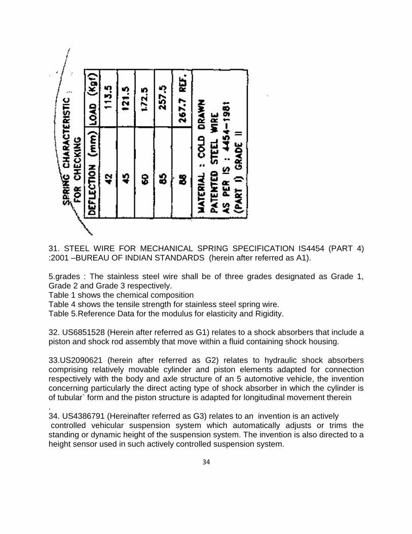
34
31. STEEL WIRE FOR MECHANICAL SPRING SPECIFICATION IS4454 (PART 4) :2001 –BUREAU OF INDIAN STANDARDS (herein after referred as A1). 5.grades : The stainless steel wire shall be of three grades designated as Grade 1, Grade 2 and Grade 3 respectively. Table 1 shows the chemical composition Table 4 shows the tensile strength for stainless steel spring wire. Table 5.Reference Data for the modulus for elasticity and Rigidity. 32. US6851528 (Herein after referred as G1) relates to a shock absorbers that include a piston and shock rod assembly that move within a fluid containing shock housing. 33.US2090621 (herein after referred as G2) relates to hydraulic shock absorbers comprising relatively movable cylinder and piston elements adapted for connection respectively with the body and axle structure of an 5 automotive vehicle, the invention concerning particularly the direct acting type of shock absorber in which the cylinder is of tubular` form and the piston structure is adapted for longitudinal movement therein . 34. US4386791 (Hereinafter referred as G3) relates to an invention is an actively controlled vehicular suspension system which automatically adjusts or trims the standing or dynamic height of the suspension system. The invention is also directed to a height sensor used in such actively controlled suspension system.

35
35.US6612410 (herein after referred as G4) relates to an invention pertains to shock absorbers and accelerators, and in particular to shock absorbers that operate in high cycling frequency applications that have low inch-pounds or medium inch-pounds per cycle but have high inch-pounds per hour. 36.US 4106596 (herein after referred as G5) relates to a single tube hydropneumatic shock absorber, and in particular pertains to a steering shock absorber. 37.US 7219881 (herein after referred as G6) relates to a shock absorber, in particular for bicycles, with a first cylinder that has a fluid chamber filled with a transmission or damping medium and in which an outwardly leading piston rod with piston for receiving the shocks to be dampened or compressed is borne axially displaceable, and with a second cylinder that has a fluid chamber filled with the transmission or damping medium and an air- or gas-filled gas pressure chamber, whereby the fluid chambers of the first and second cylinders communicate with one another via a communicating channel. 38. Opponent 1 have filed B1 to B6 documents as Exhibits but dates are not clearly provided. Similarly CC1, CC2 have been provided without dates and CC3 is an US patent grant document having patent number US8505887 having publication date 13/08/2013. In view of this office is not considering these documents mentioned in this paragraph. Further some extracts of a book named Design Machine elements by C.S Sharma ,Kamlesh Purohit(F1) has submitted but date of publication is not mentioned so this office is not considering the same. 25. Anticipation/ Lack of Novelty (Section 25(1)(b) of the Patents Act)
Arguments and submissions by Opponent 1 and Opponent 2
Learned agent for the Opponent 1 submitted that as detailed in the cited documents and
exhibits, all of them are published prior to the relevant date of filing of the application
and thereby the application suffers Section 25(1)(b), as each of them independently and
in combination with the other exhibits teach and disclose all the essential features of the
invention.
The Learned agent for Opponent 2 explained the invention with the help of a model of a
shock absorber (actual shock absorber). The learned agent argued that the said
absorber has the same constructional features as those have been worded , described,
illustrated with the drawings and claimed by the applicant. The learned agent further
submitted that ―Coil spring ― is to absorb the load , the role of a piston rod assembly is
for damping action , to reduce the oscillation motion of the coil spring and the role of a

36
helper spring (called as Bump stop ―by the opponent ) is to absorb shock load or bump
load . The learned agent for the opponent argued that applicant claims are limited to
and characterized by the selection of material for the coil spring i.e.,. Grade -2 wire and
the selection of a material for the Helper spring i.e.Polyurethene
The learned agent for the opponent 2 submitted that, the novelty of this application lies
in use of Helper spring which is made of Polyurethane material. The coil spring of Grade
2 wire is used by the applicant to compensate the high cost of the helper spring as
described by the applicant in the description. In view of this, learned agent for the
opponent argued that there is no novelty claimed by the applicant in the coil spring. The
coil spring of grade 2 materials is known in the spring and shock absorber industries
and available in the market. The selection of material of grade 2, to compensate the
high cost of polyurethane material does not amount to novelty and inventiveness.
Accordingly opponent need to establish only that helper spring of polyurethane material
is being used in the shock absorber prior to the applicant‘s priority date for the purpose
of the novelty.
The learned agent for the opponent 2 submitted that ―helper spring ―is known by
different names and in this case , the helper spring is nothing but a Bump stop, which is
being used in shock absorbers since the inception of these type of shock absorbers.
The role of a helper spring/bump stop is to avoid direct impact/collision of two metal
faces i.e., one end of the piston rod assembly and the other side end of the coil spring
120 .The bump stop / helper spring absorbs the shock load.
The role of Bump stop comes only where there is a high intensity shock/jerk/jounce due
to deep pot holes on the road or due to any other reasons. Due to the high level of jerk,
jounce, the coil spring gets compressed to the maximum level, which may lead to
collision of the two faces at the distal end. To avoid the collision of the two faces a bump
stop is provided. The bump stop has properties to absorb the impact/shock load.
The opponent 2 submitted that the applicant has given reasons in the description for
selecting of the materials for coil spring and helper spring which are based on the cost
factor and are not based on novelty and inventive steps.
Learned agent for the opponent 2 submitted the documents to prove that helper spring
is made from polyurethane material.
The Opponent 2 further submitted that in mechanical cases, novelty/ inventive steps
are decided on the basis of constructional features and interconnection of parts, and
their integral/ combined functioning and newness. On the subject title "shock
37
absorber", no patent may be given only on the basis of selection of a material for a
spring, because the use or selection of a material for "Coil Spring" or "Helper Spring"
is not a matter of novelty or inventive steps, and therefore no patent can be granted
merely based on the Grade-2 material of the coil spring and the polyurethane material
of the "Helper Spring"; Accordingly finding an exact citation as a prior art will be difficult
these type of claims are not eligible for the grant of a patent.
If a patent is considered for use/ selection of Grade-2 material for "Coil Spring"
and polyurethane material for "Helper Spring", then a patent may be granted
for Grade-3 material, Grade-4 material for "Coil Spring'' or combination of different
materials with the Helper spring.
Reply from applicant on this ground
The Learned agent for the applicant submitted that Opponent did not cite any
document or give any reason as to why the invention lacks novelty. Instead, the
Opponent repeatedly argued that the parts of the invention as claimed are known or
published in different documents. However, in no document the use of the single rated
coil spring made from grade-2 steel wire and the use of the polyurethane spring, in
combination with other parts of the shock absorber, is disclosed.
Learned agent for the applicant submitted a case, General Tire and Rubber Company
Limited v. Firestone Tire and Rubber Company Limited decided by the Supreme Court
of United Kingdom, wherein the Court, while deciding on the anticipation, laid down the
following principle:
―If the prior publication contained a clear description of, or clear instructions to do or
make, something that would infringe the patentee's claim if carried out after grant of
the patentee's patent, the claim would be anticipated. If carrying out the directions in the
prior publication would inevitably result in something being made or done which would
infringe there would be anticipation.‖
Learned agent for the applicant submitted that as none of the documents cited by the
Opponent provides a clear description or clear instructions to make the shock absorber
as described in the invention, it was submitted by the Applicant that none of the
documents anticipates the invention as claimed and Further as prescribed in the
Manual of Patent practice and procedure , to anticipate an invention as claimed, it is
necessary that all the features of the claim should be shown to have been disclosed in
one document. The Opponent failed to provide a chart mapping each and every feature
38
of the claim with the disclosure in each of the documents cited in the Representation
filed by way of Opposition.
My analysis
It is very clear that invention lies in a shock absorber for a vehicle which is characterized
single rated coil spring (116) being made from Grade-2 wire and said helper spring
(122) being made from polyurethane. On my observation, I could not able to find both
the features in a single document as provided in the guidelines of Manual of Patent
Office Practice and Procedure (the MPPP) under 08.03.02(d) prescribe that, ―A prior
art will be considered as anticipatory if all the features of the invention under
examination are present in the cited prior art.” . Based on the argument‘s and
submissions put forward by the learned agents of applicant and learned agents of the
opponents and on my analysis, I have concluded that both the Opponents failed to
establish this ground of Section 25(1)(b) of the Patents Act.
26. Section 25(1)(d)[Publicly known or used in India]
Argument and submissions put forward by the Opponents
Learned agent for the Opponent 1 submitted that Grade 2 steel spring was very much
used by opponent themselves (refer C1which is the engineering drawing for
manufacturing Grade 2 steel spring by third party and supplying to opponent. The
document C1refers to OE part no. 29171001with document dated 6.6.1999 for a two
wheeler under description "SPIRIT REAR". This model ‗SPIRIT‘ was introduced by
opponent in the market around the year 1998. Original brochure- spare parts catalogue
was distributed by opponent- DOC no. 36 02 0106 REVNO 00 dated 1.9.1998 in public
domain in the year 1998 and which original document was presented for inspection
during the hearing on10.5.2016 to the Controller, applicant and applicant's agent and
annexed herein as Annexure AA. It is obvious Grade 2 steel single rated main spring
with spring aid was manufactured and vehicles (two wheelers) mounted with such a
system was very much in the market in the year 1998 itself. Hence the invention fails
the test of inventive step as product was put to "use" in its entirety in the year 1998.
Reading these along with exhibits B1to B6, C2 to C4, it is very crystal clear that the
invention was very much put to use by many including the opponents prior to filing date
of the application.
The learned agent for the opponent 2 submitted that they have submitted EH1: invoice
details of shock absorber being sold by the opponent to different two wheel
manufactures, Invoice are dated Jan., 2008 onwards. Further EH2 a drawing of the coil
39
spring being used by the opponent. The drawing is dated Dec 2002.The bottom right
corner establishes that grade 2 material was used in the coil spring in the shock
absorber. EH3 (same as A1) BIS Standard of Feb 2001 at page 1 & 2, under the
heading ―Grade‖, it is clearly mentioned that ―The grade of spring wire depends on the
stress level and on the nature of duty ―.It clearly establishes that grade 2 wire springs
are known and are being used as per application.EH4: a drawing showing the assembly
of the shock absorber manufactures by the Opponent 2. The drawing is dated
Sep.‘1999.The box at the middle bottom clearly shows that grade 11 wire was being
used in the shock absorber industry. The learned agent for the opponent 2 submitted
that the claimed invention is publicly known in India and publicly used in India before the
priority date of Applicant‘s application.
Arguments and submissions Put forward by the Applicant.
The Learned agent for the applicant submitted that although the opponent has taken
this ground for opposing the grant of patent for the Application, nowhere the Opponent
has submitted any evidence by way of any document or reasons to prove that the article
as claimed in any claim was publicly used. However, the Opponent submitted the
drawing of a spring to prove that the shock absorber was used by public before the
invention was filed. Without prejudice, the Applicant submitted that the drawing is not a
public document; instead it is a private document. Therefore, the document does not
prove that the article of invention was used in public. Therefore, the Opponent failed to
prove the anticipation by prior public use.
The Learned agent for the applicant cited the principle laid down by the Supreme Court
in Bishwanath Prasad. The Court said that, ―What is necessary to be proved therefore is
that the prior use was public. Public use does not mean use by the public, but use in
public manner and not secretly. I want to stress the last words.‖ Thus, as long as the
use of any article is private or secret, the use cannot be said as public use. The
Opponent has failed to provide the evidence to prove that the shock absorber as
claimed in the invention was in public use. Learned agent for applicant further submitted
another case , In Lallubhai Chakubhai Jariwala, A.I.R. 1934 Mom 407, the High Court
of Bombay in paragraph 29 said that, ―What is necessary to be proved therefore is that
the prior user was public. Public use does not mean use by the public, but use in public
manner and not secretly. I want to stress the last words.‖ Thus, as long as use of any
article is private or secret, the use cannot be said as public use

40
My analysis
I have referred following case laws
In Lallubhai Chakubhai v. Chimanlal Chunilal & Co. A.I.R., 1936 Bom. 99, it was
held that public user did not mean a user by the public but a user in a public manner. It
was further held that the use of an invention for purposes of trade, whether by the
inventor himself or by others, would constitute public user of the invention. It was also
held that public sale of articles is strong evidence that the user is commercial and not
experimental. But to constitute evidence of public user, the sale must be open and in
the ordinary way of business.
In Monsanto Co. v. Coromandel Indag Products (P) Ltd. 1986 A.I.R. 712, it was held
that ―to satisfy the requirement of being publicly known as used in clauses (e) and (f) of
section 64(1), it is not necessary that it should widely be used to the knowledge of the
consumer public. It is sufficient if it is known to the persons who are engaged in the
pursuit of knowledge of the patented product or process either as men of science or
men of commerce or consumers.
Hon’Ble IPAB ordered in OA/4/2009/PT/CH that We do not agree with the appellant
that disclosure in lecture will not amount to anticipation. Disclosure of invention by the
inventor even to a single person of public before the priority date of patent destroys the
novelty of the invention. Therefore, the claimed invention is anticipated by this
document
I have referred Patent law of by P. Narayannan Fourth Edition, Page no: 367 . It is given
that PLG research Ltd v Ardon International Ltd (1993) FSR.197 at 225 that ―to form
part of the state of art , the information given by the user must have been made
available to at least one member of the public who was free in law and equity to use it‖.
In view of this, I have deiced to consider the Spirit spare parts catalogue (herein
referred as AA) (DOC.NO.36020106 dated 010998) referred Plate no: 28 rear shock
absorber, Fig no:5 (part no: 29171001)—Rear shock absorber spring ..
PE/29/MM/CH/A542. As per this grade 11 steel wire has been used and other related
drawings supplied by the opponents (C1 to C4)..

41
.
It is very clear that invention lies in a shock absorber for a vehicle which is characterized
single rated coil spring (116) being made from Grade-2 wire and said helper spring
(122) being made from polyurethane. On my observation, I could able to find use of
grade 2 wire in the drawings supplied for manufacturing but could able to find only bump
stop with rubber. Based on the argument‘s and submissions put forward by the learned
agents of applicant and learned agents of the opponent and on my analysis, I have
inclined to accept the learned agent for applicant‘s argument that Opponents failed to
establish this ground.

42
27. Section 25(1)(e)[Lack of Inventive step]
Arguments and submissions made by the Opponents
The Learned agent for the opponent 1 Submitted that claim 1characterized portion is
"said single rated coil spring 116 being made from Grade-2 wire and said helper
spring 122 being made from polyurethane". This combination lacks inventive step due
to following evidences put forth in this proceeding by the opponent :Further the learned
agent argued that the problem addressed in the invention and solution provided in the
invention, was previously seen, appreciated and needed implementing solutions was
made available much prior to the relevant filing date of this application such as in
documents A1, B1to B6,C1 to C4along with Z1 to Z12 and Y1 to Y11 also.. The
existence of prior art and/or knowledge available in public domain teach towards
the alleged technical and the commercial direction taken by the applicant.
The learned agent for the Opponent 1 argued that provisional specification where the
field of provisional specification states that the invention is related to "shock absorber
for a two wheeler" and also through the complete specification where the field of
complete specification states that the invention is related to "shock absorber for a
vehicle". In the provisional specification in its first para of "Description‖ discloses use of
PU spring aids in tandem with main springs in passenger cars. The provisional
specification in its second para of description states "the present invention relates to
development of a combination of single rated spring with the spring-aid, for a two
wheeler application. The use of single rated spring helps reduce the material content,
thereby lowering the cost, thus offsetting the higher cost of spring-aid, vehicle achieving
a higher level of ride comfort".
The Learned agent for the opponent1 submitted that, admittedly, therefore the
contribution of the applicant is limited to
a Use expensive PU spring as spring-aid {as known in prior art)
b. Use single rated main spring instead of non-linear main spring to reduce
material content thereby reducing cost and offset the expensive PU spring aid.
{select the cheapest combination of the many combinations known in prior art)
The learned agent for the Opponent bring out following issues
a. Is use of linear main spring in shock absorber an improvement?

43
Passive suspensions are designed with linear spring and dampers. The ride comfort
perceived by rider of vehicle has been shown to depend on the speed, acceleration of
the vehicle and also on rate of change of acceleration. A good suspension system
would stiffen up for larger rates and soften for smaller rates of acceleration input from
the road when the vehicle moves over bumps. This is related to certain desirable "non-
linearity" both in spring and dampers. Hence many prior art are relating to using "non-
linear spring" in shock absorber system in which progressively varying spring rate is
achieved accordingly much before to filing date of this application. Hence adopting
linear main spring is not inventive in the eye of a skilled person.
A linear spring has a linear relationship between force and displacement i.e., they are
directly proportional to each other. A non-linear spring has a non-linear relationship
between force and displacement i.e., they are not directly proportional to each other.
Non-linear springs have an advantage that such spring exerts an inconsistent amount
of forcei.e. does not execute constant rate of force per distance travelled. Also non-
linear springs can have dual-pitch, multiple-pitch, etc. This requires one to only adjust
the pitch between some of the coils for it to take one to a different amount of load to
meet one's required loaded heights. So basically with a non-linear spring, at the
beginning of the compression cycle, the spring constant 'K' is lower and the spring can
therefore be compressed more easily. Thus puts less stress on the other internal
components such as piston because the spring is easier to compress. As the spring
is compressed, the spring constant increases which eventually equates it to linear
springs of the same rating strength-wise. Hence non-linear spring is nothing but putting
several small linear springs with different 'K' valves together. The art has improved from
using mere linear single rated springs in shock absorber to non-linear springs, and
hence adoption of linear main spring in a suspension system is not inventive in the eye
of a skilled person.
b. Is a polyurethane spring aid referred in the application same as a polyurethane bump
stops referred by others?
It is known that use of rubber as a spring medium has only relatively limited application,
in vehicle suspension system and use of a urethane elastomer is usually preferred for
suspension system, because unlike rubber materials it can provide a more progressive
stiffening characteristic over a under range of deflection. A urethane spring material is a
polyether-elastomer that reacts similarly to an incompressible fluid. The volume of
material moved by compression is displaced laterally in the form of bulging sides. An
approximation to the change in diameter of a typical cylindrical urethane springs can be

44
made by increasing the diameter by the size of compression. Hence urethane as a
spring material is known in prior art and using a urethane spring aid in a suspension
system is not inventive in the eye of a skilled person.
From the provisional specification under "Description" {para 1 and para 2)
admittedly, combination of PU spring and with main springs in a shock absorber is
known in passenger cars and more specifically known to applicant themselves. Thus
the applicant is intending to pick a combination of PU spring aid with a main spring,
which main spring shall be single rated for sake of reduction of material and thereby
cost reduction and further use grade 2 material for sake of further cost reduction of
the main spring for using the known prior art {used in passenger cars) into a
cheaper two wheeler. Thus the teaching flowing from the provisional specification
{Description) is that- PU spring + main springs combinations is known in the art for use
in vehicle {passenger cars) and the applicant is exploring the "cost effectiveness" of one
of the combinations for using the known art in two wheelers. Accordingly it is submitted
that availability of the aforesaid combination claimed in the application flows from the
known prior art and the selection disclosed by the applicant in the claims/specification
required no extraordinary efforts on the part of the applicant. The 'cost-offset‘
requirement is a matter of mere commercial decision of a known technology and does
not involve any inventive ingenuity in doing so. Hence the application has failed
problem-solving test at the first instance itself which is on the basis of its own disclosure
in the provisional specification.
The opponent 1 has submitted A1(IS 4454) in opposition proceeding (Exhibit- A1 of
notice of opposition) which is IS4454 revision 2001. It is submitted as per this
document, Grade 3 steel spring was introduced in IS4454 only in 2001which means
Grade 2 steel spring was previously used by all Indian manufacturers on all vehicles
including two wheelers at all times with no option for selecting Grade 3 steel spring
until 2001for passenger cars and two wheelers. When a skilled person refers to IS
4454, it will be understood that, as per IS 4454, Grade 2 steel spring and Grade 3 steel
spring coils have same chemical proprieties and modules of elasticity but Tensile
strength K/modules of rigidity is different. So mere substitution for cost reduction
cannot be an inventive step without justifying technical reasons for substitution between
Grade 2 steel spring and Grade 3 steel spring in a functional mechanism such as shock
absorber which is one of the critical components of suspension system and is generally
carefully designed by engineers to handle shock impulse and dissipate kinetic energy.
The role of spring in a shock absorber is to reduce the amplitude of disturbances
leading to increase in comfort and improved ride quality. Hence, the designing of
spring in a suspension system is very crucial and cannot be blindly substituted with a

45
mere purpose of cost reduction. Lot of thoughts and science is put behind designing
the coil rate of spring, length of spring , diameter of coil, number of spring and type
of coils along with other technical parameters surrounding the operating conditions
by a typical skilled person in the art. But this invention merely follows from a normal
product design and development for commercial exploitation, lacking innovation and
fails the purposeful test of inventive step which is mandatory\( for test of patentability.
An ordinary skilled person in the art could have very easily considered the option
of combining the materials as disclosed and claimed in the invention from the prior
art. The subject matter is thus wholly identified in documents B1to B6, C1to C4, Z1to
Z12 and Y1to Yll. B1discloses actual availability of real products in the market - PU
helper spring to be used in shock absorber. Patents marked Z1to Z12 disclose the
use of PU material for making springs.
US 4756516 was elaborated for better understanding of the prior art. Figure 2 of
invention literally matches figure 5 of Z1confirming the existence of near identical prior
art much before the filing date. All of these patents teach using PU spring aids/PU
bump stop with main spring in a shock absorber. Documents C1to C4 relate to the
manufacture of the linear main spring of grade 2 with a spring aid as early as 1998 by
the opponents themselves. From the said cited documents, there is no doubt that the
application suffers lack of inventive step, as the skilled person would have been
expected to arrive at the solution in claim 1, combining his knowledge of the prior
art, with his common general knowledge in the field and his commercial sense.
Document A1, clearly proves as per IS4454 (prior to revision of 2001) that only Grade 2
steel spring must have been "used" by all without option of Grade 3 steel spring.
C1clearly proves the use of 'Grade 2' steel spring coil on its "Spirit‖ model two wheeler
launched for sale in the year 1998 by the opponent. C2 and C4 also prove the actual
use of the invention and available in public domain prior to filing date of the application.
Use of PU material for springs is also known in prior art as putforth in Z1- Z12,Y1-
Y11,B1- B6. The applicant themselves admit to have identified closest prior art i.e.,
identified the product in passenger cars, one of the most relevant prior art for this
case. Thereafter instead of addressing the 'technical' problem in adapting the known
prior art from 'passenger cars' onto 'two wheelers' the applicant in view of the 'high cost'
of some of the combinations available in prior art product, simply teaches the skilled
person to do 'cost cutting' by using 'cheaper material' and 'lesser material' for
adaptation of the product from passenger car to two wheeler in the provisional
specification. This itself is in contradiction further, since the claim in the complete
specification is relating to a 'vehicle' and not just to "two wheeler" as envisaged and

46
explained in provisional specification. Hence the two specifications and claims fail
miserably in accurate disclosure and proper claims. The point is skilled person could
have and would have arrived at the invention by adapting or modifying {as suggested in
the application} the prior art if there was a need for cost cutting and hence the invention
is obvious to the person skilled in the art (using cheaper material, lesser material and
combination thereof}.
For these reasons, it can be concluded the subject matter will be obvious to the person
skilled in the art and he would have arrived at the subject matter of claim 1in an obvious
manner. Nothing inventive can be seen in using the combination of Grade 2 single rated
spring coil with PU spring aid in association with a shock absorber. The skilled person
aiming to apply the combination of main spring with spring aid in a shock absorber
would, based on his/her technical knowledge and commercial sense, select this
combination in order to limit the cost of the end product if at all desired. There is no
disclosure of an improved technical effect associated with the said selected main
spring and selected spring aid in the specifications/claims, hence the claimed
combination is very obvious from prior art and it cannot give rise to an inventive
step also, but merely be selected as obvious for the skilled person for cost calibration
purposes of a shock absorber designed by the skilled person.
Accordingly, it is submitted that a skilled person can easily follow the prior art to
reach the combination referred in claimed invention, for commercial exploitation of a
known subject matter and hence the product allegedly claimed in the impugned
application is obvious and more so lacks inventive merit on the face of admission
of applicant themselves in the provisional specification and read with teachings of
A1,B1 TO B6, C1 to C4, Z1 to Z12 and Y1 to Y11.
Thus the assertion of applicant for having designed "less cost" product allowing to be
used for two wheelers becomes obvious, based on the combined teachings of said
documents. The product is outcome of ordinary skill, common sense and commercial
skill and exposes no technical skill of the applicant. Furthermore this objection is
applicable assuming that the shock absorber is only for the use of two wheeler with
the said combination as specified in the provisional specification.
If the same logic was to be extended onto ―shock absorber for. a vehicle" of the
complete specification, then the claim fails in its entirety as it wholly falls within the
scope of prior art admitted by applicant themselves.
Beyond the claims, the supporting documents such as the provisional specification
and complete -specification also do not demonstrate any technical advancement of

47
the claimed subject matter {i.e., combination of PU spring aid + single rated grade
2 main spring) as compared to the already existing piece of information in prior art{s).
Both the documents are silent on the technical advancement. Thus in this case the
invention lacks inventive step due to failure to demonstrate improvement over known
prior art if at all achieved in the alleged application. The said application refers to
significant advantages of maximum comfort to the passengers but there is no evidence
to prove that the application has the improved and unexpected advantageous effect.
It is respectfully further submitted the problem underlying the invention seems
not to determine the effective technical working of shock absorber but lies merely in
identifying the 'cost' management, and hence demands no inventive ingenuity. Further,
it is to be understood that a person skilled in the art would have known that PU spring
aids are expensive over rubber aids and single rated Grade 2 main springs are cheaper
than non-linear grade 3 main springs and hence the selected combination use as
claimed in claim 1and other claims on the basis of 'cost factor' is obvious. It is
submitted that the 'subject matter as a whole' was obvious at the time the invention
was made, most certainly to a skilled person in the art, due to abundant prior art
available, and hence it is clear cut motivation to arrive at the 'claims' of the impugned
application from teachings of any of the prior art references putforth in notice of
opposition, separately and in combination. The skilled person can readily perform the
invention for commercial exploitation over the whole area claimed without undue
burden and without needing inventive skill and thereby the application suffers
obviousness.
The essence of the claim is in the 'characterized portion' of shock absorber, the shock
absorber may be considered inventive only if the actual way of selecting/arranging the
main spring and spring aid was not obvious, irrespective of whether or not there was a
desire to produce the product. The inventive concept in this particular situation of this
application is the selection of materials of main spring and spring aid. Since the identity
of the main spring and spring aid and their utilities/characteristics have been predicted
in prior art, inventive concept cannot subsist in the said shock absorber and definitely
also in the method of selecting materials on the basis of cost as suggested in the
specification. Hence the application fails the test of non obviousness.
The learned agent for the Opponent 1 has filed Expert affidavit by Mr.Rajeev
Mokashi
a.The contents of provisional specification and complete specification (Form 2) are
indeed inconsistent as the narration in provisional specification starts with a "shock

48
absorber for a two wheeler" and ends with a "shock absorber for a vehicle in claim 1"
in Form 2- complete specification. The title of the Invention also changes from "shock
absorber with Spring Aid" to "shock absorber with Helper spring".
b. Assuming that applicant is seeking a claim for 'shock absorber for a vehicle' as
claimed in claim 1, the entire content of claim 1 is well known in the prior art for
many years. As a subject matter expert I can confidently say that using PU spring
aid is an art used on vehicles such as passenger cars for many decades, since
1960s. Use of Spring aid has resulted in changing the spring characteristics from dual
rated to single rated. I have not identified any new material or new construction in
the patent application challenging my knowledge on the subject of design of shock
absorber in the said application.
c.In my view the core issue - is whether bump stop is same as a helper spring or not,
in which I understand that opponents and applicants having different opinions - The
opponent stating that Helper Spring is essentially Bump Stop which is in use in
automobiles across world for many years and applicant stating that it is not bump
stop but a helper spring with additional damping function -an invention. My opinion
as a subject matter expert is that Helper spring is indeed a Bump stop or
spring aid without significant damping function & works along with coil
spring at the later part of suspension compression stroke. Every bump stop
works as a spring aid. It contributes more or less depends upon its
engagement stroke and thus also on its length. Bump stops of various length
depending on shock absorber stroke and ride & handling requirements are
commonly used. It is well known that bump stops or spring aids are also made
of polyurethane (PU), which is visco-elastic material. Urethane is elastomer
capable of good impact resistance and durability & can retain elasticity and
strength over a wide range of hardness and impact vis-a-vis rubber as
elastomer. As per my knowledge, unlike steel springs, the dynamic spring rates of
various urethanes can range many times greater than their static spring
rates, depending on the compound, hardness and density. Also, unlike steel
springs, a small percentage of the input energy is converted to heat due to
hysteresis losses in such visco-elastic material. Hence in my view, polyurethane has
been known as an ideal compound to use for shock absorption and vibration
isolation in many industries, including automotive industry. For example, such PU
springs were used in shock absorber way back in 1960s (refer encl. evidence:
Cellasto SO years BASF). Typically manufacturers custom fabricate a product to
specific chemical make-up and durometer I density to provide the stiffness
performance,taking into account the main factors that affect the spring rates,

49
shape factor, density and durometer hardness, to offer many custom products, with
varying Load Deflection characteristics to meet different needs. In the present
application, in my view the applicant is only calling it by a different name- the
same old PU Bump Stop as Helper Spring. Other current names for the same
part are Spring Aid & Jounce Bumper. I do not identify any new technical
material/disclosure in the application disclosure than what has been explained
above and thereby I state that merely calling such a PU Spring aid I Bump Stop
by a new name such as a "helper spring" & providing solution such as using a
PU spring aid with a single rated main spring for a shock absorber is not
useful to knowledgeable persons in the industry, as it is a knowledge already
available in the industry. I confidently state that having read the documents
filed by the applicant, there is nothing new or useful material that is disclosed.
d.working of Polyurethane helper spring /Bump stop and coil Spring: The title of graphs
shown in figure 4 is "graphical representation of energy dissipated in the existing and
the present subject matter". There are two curves.shown in graph: 400 ->Conventional
(presumably with rubber Bump stop & 402 ->with PU Spring aid. Working of bump stop
(referred as helper spring in the specification) along with coil spring at the later part of
stroke is very basic concept used in many suspension systems from long ago. Any
suspension design using a coil spring with a bump stop/helper spring will show identical
graphs based on shape, material and hardness I density of visco-elastic material. It is
possible to create graph with curve as 402 using rubber also. In fact various suspension
designs and Patented prior art disclose that the bump stop or helper springs are
positioned at the lower end of the suspension system , for example below the coil spring
(similar to as shown in Figures 2 and 3 of TVS Application) . Hence it is very obvious
that the bump stop/ helper spring will work or take part at the later part of the
suspension stroke. incidentally, the graph is Load Vs Deflection and plotted in one
direction only. Hence, there is no way to represent energy dissipated by Rubber or PU
Bump stop. We need to plot graph such as shown below to know energy dissipated by
hysteresis. Thus the graph shown in figure 4 does not possess any novelty and is
superfluous, without any concluding & supporting data.

50
e. It is not evident from Patent specification what are additional effects achieved by
applicant and how it is achieved as there appears no constructional differences w.r.t. to
known constructions of shock absorber. Merely, by giving a different name to known
element (i.e. calling it as helper spring or bump stop) does not change the behavior of
the element and can't produce any different characteristic like improved function by
bump stop/helper spring.
f. Heat Dissipation by suspension system: It is well known fact that the suspension
system ( for example, Spring) absorbs shocks from road induced vibrations due
to bumpy roads, ditches etc. and this absorbed energy needs to be dissipated in
form of heat by shock absorber( this has been correctly stated by Applicant.) It is
a well-known principle of transfer of energy from one form to other form. The
suspension systems are designed with controlled damping (damping ratio for
shock absorber) to ensure durability of suspension elements and rider
comfort.Rider comfort would be adversely affected if there is additional damping
force, generated during compression stroke by PU Bump stop. Hence,
shock absorber is expected to have minimal damping in compression stroke.
PU Bump stop would also need to provide minimal hysteresis in compression
stroke to improve ride characteristics. However, applicant states that energy
dissipation by PU Bump stop is advantageous in improving ride comfort. Also,

51
applicant does not provide quantitative data on how much is the dissipation of
energy by PU Bump stop Vs that by shock absorber in typical one cycle of
known amplitude and cycle time. Also, it is a fact that PU Bump stop would
function only towards later part of compression stroke Vs shock absorber which
works for the complete range of stroke. Shock absorber would dissipate more
energy if we change valves to provide higher damping ratio, with precaution that ride is
not becoming harsher.
g.Use of Grade 2 wire and PU helper spring: It is presumed that spring material
grade is as per IS 4454. It is correctly stated by applicant that the stresses in
suspension spring would be less, as limiting load supported by spring is
less, due to Bump Stop sharing it. This would lead to lower grade of spring
material for selection. However, while designing any element/system, Design
Engineer would always use his part material choice/description depending
upon functional & strength requirement as well as market requirement or
organizational guidelines etc. Based on this the 'designer selects/make choice
suitable material available in the market as the properties of these materials are
well known/published in various catalogues Standards etc. The cost of these
elements is also available to designer. Thus the designer has various choices of
selecting a material .The designer can afford to select a high cost material if the
market is ready to pay higher cost for additional durability or performance and
vice versa. The Application prima facie focuses on selection of material from a
range of various known materials, with known properties and cost, which is
general practice in all companies engaged in design activities. Hence selection of
grade 2 wire and PU helper spring does not form any new learning to society.
The learned agent for the opponent 2 submitted that this ground of opposition is based
on two merits ; firstly it is obvious, it lacks inventive step in view of the documents cited.
The learned agent for opponent 2 submitted that with the documents cited it is clearly
established that the helper spring of polyurethane material is known in the shock
absorber industries; further coil spring of grade 2 material is used by the applicant in the
shock absorber to only compensate the high cost of helper spring.
The learned agent for the opponent 2 submitted that the general meaning of Obviousness ―is that it is known to a person skilled in the art and accordingly the opponent submitted that the claimed invention does not have any inventive feature. The applicants claimed invention does not have newness in constructional features of the shock absorber. The applicant claims novelty and inventiveness on the basis of known use of known material in a coil spring and a helper spring as worded and described, is functioning independently and in the rare case of extreme jerk or jounce or shock, the

52
helper spring role comes in to the picture to absorb shock. Learned agent for the opponent 2 submitted that a person skilled in the art may select a helper spring or a coil spring made of the material as claimed by the applicant as per the application of the shock absorber. The important point is that the applicant is only selecting the material, which is one type of permutation and combination for selection of material as per application/use of the shock absorber. A person skilled in IPR will clearly understand that the Applicant's claims are not
eligible for the: grant of a patent as the invention does not have novel construction of
the shock absorber, and the Applicant's claims merely relate to a known use of a
known material. Selection of a material for "Coil Spring" or "Helper Spring" is
solely based on the application of the shock absorber or the cost of the shock
absorber; There is no inventiveness in the selection of the material. , which is known
in the spring and the shock absorber industry.
The Applicant has characterized in Claim one " characterized in that said spring 116
being made from grade -2 wire and said "Helper Spring" 122 being made from
polyurethane." This means that the features or constructional features claimed prior to
the word 'characterized' in claim one, are not novel and are known in the industry and
is therefore prior art. As discussed above, the complete description as worded,
described and claimed does not have novelty and Inventiveness.
Reply from the applicant
Learned agent for the applicant submitted case laws
In paragraph 27, the Supreme Court in Bishwanath Prasad, A.I.R. 1982 S.C. 1444, laid
down the test for determination of inventive step. The Supreme Court said that, ―Had
the document been placed in the hands of a competent craftsman (or engineer as
distinguished from a mere artisan), endowed with the common general knowledge at
the 'priority date', who was faced with the problem solved by the patentee but
without knowledge of the patented invention, would he have said, "this gives me what
I want?" (Encyclopedia Britannica; ibid). To put it in another form: "Was it for practical
purposes obvious to a skilled worker, in the field concerned, in the state of knowledge
existing at the date of the patent to be found in the literature then available to him, that
he would or should make the invention the subject of the claim concerned?" Thus,
according to the Supreme Court, the inventive step should be assessed with
reference to a person skilled in the art. If the problem faced by the patentee can be
solved by such a skilled person in the art by referring to the cited prior art then the
invention claimed by the patentee is obvious and is not patentable.

53
Common General Knowledge: In paragraph 27, the Supreme Court in Bishwanath
Prasad, A.I.R. 1982 S.C. 1444, articulated a profile of the person skilled in the art. The
Supreme Court said that, ―Was it for practical purposes obvious to a skilled worker, in
the field concerned, in the state of knowledge existing at the date of the patent to be
found in the literature then available to him, that he would or should make the invention
the subject of the claim concerned?" (Emphasis added by underline). Thus, the
Supreme Court defined the person skilled in the art as a skilled worker who is having a
knowledge that he could have found in the literature available to him.
In the case of Roche v Cipla, the Delhi High Court delivered judgement in November
2015, RFA (OS) 92/2015, wherein the Court relied for claim construction on the
principle laid in Unichem Laboratories. The court said, ―Before we apply the
aforenoted legal position to the facts of the instant case we need to discuss the legal
position concerning construction of claims. In the decision reported as AIR 1969
Bombay 255 FH & B Vs. Unichem Laboratories it was held that specifications
end with claims, delimiting the monopoly granted by the patent and that the main
function of a Court is to construe the claims without reference to the specification; a
reference to the specification being as an exception if there was an ambiguity in the
claim. Claims must be read as ordinary English sentences without incorporating into
them extracts from body of specification or changing their meaning by reference to
the language used in the body of the specification.‖
The learned agent for the applicant submitted that Opponent objected to the grant of the
patent for the Application on the ground under Section 25(1)(e) that the invention as
claimed in any claim lacks inventive step or the invention is obvious for the person
skilled in the art. However, the Opponent could not provide evidence of disclosure in
any document that the single rated coil spring made up of grade-2 steel wire and the
polyurethane helper spring are used in any shock absorber. The Opponent always
misunderstood the use of a polyurethane bump stop as the polyurethane helper spring.
The Applicant submitted that the bump stop and the helper spring, which is also called
as a spring aid, are different. Whereas the helper spring operates as main spring to
oppose the upswing of a wheel over a longer stroke, the bump stop operates to provide
cushion against bottoming out of the main coil spring. In support of this, the Applicant is
submitting herewith a copy of an affidavit which provides an opinion of an expert. As per
the expert,
―Spring aid enhances the characteristics of the spring over a considerable period of its
travel, whereas the bump stop acts only for a very short period of travel and effectively
acts as a stopper to avoid bottoming. As the name suggests, the bump stop comes into

54
action only towards end of stroke of the shock absorber. The bump stop helps to
prevent bottoming of the shock absorber whereas the spring aid helps to improve ride
comfort by way of re- enforcing the dynamic characteristics of the spring and
also preventing bottoming.‖
The learned agent for the applicant submitted that the Opponent has failed in
demonstrating that the invention as claimed lacks inventive step, because each of the
documents cited by the Opponent and the combination thereof does not disclose all the
features of the claimed invention. The Opponent has cited 29 US documents.
The Applicant submitted that the inventive step as claimed in the invention lies in the
arrangement of a single rated coil spring made up of grade-2 steel wire and a
polyurethane helper spring used in combination with other components or parts of a
shock absorber, working in tandem with each other and the fluid chamber to provide
comfortable ride to a passenger by effective dissipation of the heat without any time lag.
Learned agent for the applicant submitted that as evident from the discussions related
to the prior arts cited by the Opponent, none of these prior arts, taken either alone or in
any combination thereof, would enable a skilled person to arrive at the invention..
Furthermore, the Applicant submitted that the invention also has a distinct advantage
when considered in light of the cited prior arts. The arrangement of the single rated coil
spring and the helper spring provides the technical advance of effective dissipation of
the energy during the dampening process without any time lag. This ultimately provides
the comfort to the rider of the vehicle. Further, the use of grade-2 steel wire for
manufacturing the single rated coil spring proves to be cost effective solution.
The Applicant submitted that the person skilled in the art is an engineer working
for at least 6 to 8 years in the field of development of a suspension system for a vehicle
or in the field of development of a shock absorber. On the date of the Application, a
person skilled in the art would have the following knowledge: that the spring should be
multi rated and should be made from Grade 3 or Grade 4 wire to take care of dynamic
load; that the bump stop should be provided to avoid bottoming of the spring; that Grade
2 wire should not the used to manufacture the spring for a vehicle; and that the spring
should be multi rated. Such a skilled person in the art would never refer the cited
documents to solve the problem of improving the comfort of the ride or, even if he refers
to such documents, he would never come with the idea of using a single rated coil
spring made up of Grade 2 steel wire and using a helper spring made from
polyurethane, working in combination with a fluid chamber. Therefore, if we apply the
test laid down by the Supreme Court in Bishwanath Prasad, the skilled person who was

55
faced with the problem solved by the invention as claimed in the Application, but without
knowledge of the patented invention, would not have said, "This gives me what I want?
Therefore, the invention as claimed in the Application is inventive.
In order to prove that the invention as claimed lacks inventive step, the Opponent
should have produced evidence of what the knowledge a person skilled in the art would
have possessed on the date of the application and, in view of his knowledge, how the
cited document or documents would have made the invention obvious to him. The
opponent neither cited the relevant document nor evidenced the knowledge that a
person skilled in the art would have possessed on the date of the Application. The
Opponent made general statements without any reasoning and opposed the Application
on the ground of lack of inventive step. Therefore, the Opponent has miserably failed to
substantiate the ground for lack of inventive step. In view of the above, it was submitted
that the Opponent has failed to counter the ground of lack of inventive step of the
invention as claimed.
Learned agent for the applicant also submitted a evidence by way of an affidavit
of Mr.Ojus Joseph Jacob
That I was approached by the aforesaid Applicant to examine and provide my opinion
on the following queries in the context of a patent application number
1120/CHE/2007:
A. Whether the polyurethane helper spring and the linear spring are working together,
as shown in Figure 4 of the specification for patent application number 1120/CHE/2007.
B. Please explain how the rider comfort is dependent upon the heat dissipation
characteristics of a shock absorber,
C. What is the difference between spring aid or helper spring with respect to bump stop
D. What are the challenges to design a shock absorber, such as space, height,
rate of heat dissipation, cost, manufacturing complexities
E. What is normally understood by a person skilled art the meaning of Grade2 wire for
manufacturing of a spring for the shock absorber
F. Explain the working of a linear and a non-linear spring. What are the relative
advantages?
Ans for A : The polyurethane helper spring is activated by a one end of a damper after
first part of travel of linear spring. Thereafter, the polyurethane helper spring and the

56
linear coil spring work in tandem during the latter part of the stroke to provide comfort to
the rider by effectively dissipate the energy with minimum time lag. As can be
understood from Figure 4, the linear spring is absorbing and dissipating the energy for
the first part of the travel of the shock absorber and thereafter the polyurethane helper
spring together with the linear spring absorbs and dissipates the energy logarithmically.
It is inherent from the construction and the relative placement of the polyurethane helper
spring the combined effect is achieved.
Ans for B: A shock absorber works on the principle of absorbing shocks coming from
the road and dissipating the shock energy in the form of heat, thereby ensuring
comfort and vehicle control to the rider. As the vehicle moves over bumps and
potholes, due to the movement of the sprung mass and the unsprung mass, the
restricted damping of the shock absorber fluid causes temperature rise. This heat has to
be dissipated at a desirable rate. Otherwise the damping medium will lose its
effectiveness due to factors like reduced viscosity and cavitation. Thus heat dissipation
characteristics are important to enable the shock absorber retaining its capacity for
continued shock absorption.
Ans for C: Spring aid enhances the characteristics of the spring over a considerable
period of its travel, whereas the bump stop acts only for a very short period of travel and
effectively acts as a stopper to avoid bottoming. As the name suggests, the bump stop
comes into action only towards end of stroke of the shock absorber. The bump stop
helps to prevent bottoming of the shock absorber whereas spring aid help us to improve
ride comfort by way of reinforcing the dynamic characteristics of the spring.
Ans for D: Typical challenges in designing a shock absorber for an automotive vehicle
are many, starting from the space available to mount the shock absorber to the finer
requirements of aesthetic appeal, corrosion and durability requirements. The challenges
arise primarily from matching engineering and design feasibility with customer
requirements.
Ans for E. Spring wire is typically made of different grades of material which refer to the
tensile strength of the wire as per Indian Standard (IS) 4454. Grade number refers
to particular level of strength. Higher the grade number, higher is the strength of
the wire & higher is the cost of the raw material owing to higher additives of other
chemical elements and process treatments of the spring wire.
16. Space constraint in shock absorber design & packaging enforces use of
higher grade of wire. Typically higher grade wire has additives in form of noble additives

57
to increase strength, thereby increasing cost. A spring made of grade 2 can have a set
problem if used in an overstressed condition. For the same over stressed condition the
solution would be to opt for a higher grade of wire material.
11. The key challenges to design shock absorber are:
1) Layout space - Stroke availability and outer cage envelope.
2) Height of vehicle & ground clearance
3) Packaging of parts in vehicle
4) Energy to be dissipated & rate of dissipation under dynamic conditions
5) Payload of vehicle & occupant weight (function of above 4)
6) Manufacturing feasibility of design
7) Cost of material &total manufacturing cost
8) Material selection & availability
9) End fitting points
10) Ride characteristics
11) Installation angle on vehicle
12. The fitment space constraint (more particularly on a two wheeler) decides the
available stroke for the shock absorber which has a large influence on the ride
characteristics. Sufficient load carrying capacity is necessary to prevent bottoming for
better comfort a suspension that has a longer travel would be preferred. The space
limitation in the lateral direction also puts challenges on the size of spring that can be
packaged.
13. The end fitment points play an important role in achieving desired ride
comfort and often it is a challenge to find the right points due to the packaging
constraints of other neighborhood parts.
14. Some of the design features to overcome these technical challenges and meet both
business and end customer requirements lead to to higher cost solution in terms of
costly materials and costly process, which can impose trade off challenges.The

58
manufacturing complexities also increase with technical solutions like use of higher
grade springs, improved coatings, high accuracy child parts of the damper etc.
Ans for F: Linear rated spring has a single stiffness rating throughout its travel while a
non-linear spring will have more than one progressive stiffness rating.
18. Use of a non-linear rated spring in a suspension caters to the requirement of
carrying variable loads under different terrain conditions with better comfort and vehicle
stability for the available travel of the shock absorber.
19. While non-linear spring enables achieving exponential ride characteristics
&enhanced ride comfort, it inherently results in adverse cost impact due to need
for selection of higher grade material or thicker wire diameter.
My analysis
Objective of the invention: Present invention proposes a method of increasing the
performance and durability of shock absorbers by ensuring the energy absorbed by the
spring of the shock absorber is efficiently and effectively dissipated to the surroundings
and this leads to substantially improvement in passenger ride comfort and durability of
the shock absorber.
Solution for the problem :A shock absorber comprises of single rated coil spring , made
up of a grade 2 wire , supports the weight of the vehicle and absorbs road shocks
rapidly .The energy absorbed by the single rated coil spring is then dissipated in the
form of heat by dampening fluid of the shock absorber. the said shock absorber also
comprises of a helper spring that is slidably and concentrically disposed on the piston
rod .The helper spring is made of polyurethane and has diameter that is substantially
less than that of the single rated coil spring, Polyurethene possesses the property of
efficiently absorbing and dissipating energy, thereby aiding single rated coil spring in
energy dissipation.
1.US4756516 (Z1) relates to a resiliently deformable element made of an elastomeric
material having a microcellular structure, which can be used as an end stop in a motor
vehicle suspension, in particular a suspension of the Mac Pherson type.

59
Reference numeral 1 denotes
Shock absorber
2----- coil spring coaxial with it
3—deformable element
FIG. 4 schematically represents a section of a suspension on which the deformable
element of the invention is utilised;FIG. 5 is a resilient characteristic of a suspension
with the deformable element of the invention.
According to the present invention there is provided a resiliently deformable element
made of elastomeric material having a microcellular structure which can be used as an
end stop in a motor vehicle suspension, the said element having a tubular from and an
axial hole through which passes the rod of a shock absorber, an upper end adapted to
engage a suitable seating of the motor vehicle body and a lower end contacted in use
by a surface of the shock absorber casing, characterized by the fact that it includes a

60
first part which is delimited internally and externally by coaxial surfaces and a second
part of annular form coaxial with the first part and which projects axially therefrom, the
area of any section of the said second part taken on a plane orthogonal to the
longitudinal axis of the element being less than half the cross sectional area of the said
first part taken on any such plane, and the axial length of the said second part being
less than that of the said first part.
The deformable element 3 of the invention, which is substantially of tubular form, is
traversed by the rod 6 of the shock absorber and its upper end engages on another
annular rubber bearing block 13 with the interposition of a plate 23. The axial length of
the deformable element 3 is chosen in such a way that the lower end thereof will not be
in contact with the casing 4 of the shock absorber when the suspension is in its rest
position, but is located at a certain distance from the casing itself as is clearly seen in
FIG. 4.
As soon as the upper surface 24 comes into contact with the surface 25 of the
deformable element 3, this latter also contributes to supporting the load which acts on
the suspension, together with the spring 2, and therefore the overall characteristic of the
suspension now also depends on the characteristic of this element.
The deformable element of the invention is made of an elastomeric material having a
microcellular structure, that is to say comprising closed and open cells of extremely
small dimensions; conveniently such elastomeric material is a polyurethane or a rubber.
The element is made by means of the usual forming technologies for microcellular
materials, utilizing molds able to form such an element.
Upon continuing deformation of the suspension, the first part 16 of the deformable
element 3 is also deformed which, during the deformation itself works substantially
under compression; when this part is deformed it still has an annular form and is
delimited externally by a surface which has a diameter greater than that of the
cylindrical surface 18 which delimits this part in the undeformed configuration.
It has been found that the characteristic of the element 3 is not linear and has an
increasing slope with an increase in the deformation, that is to say the rigidity of this
element increases with an increase in the deformation itself.
It has been found that the deformable element 3 has an almost indefinite life and is not
subject to rupture by fatigue; this favorable result depends on the fact that all the
material of the deformable element works substantially under compression; in fact, even
the second part 19 of this element, while being subjected to very high deformations,

61
works solely under compression as distinct from what took place in deformable
elements of the prior art type in which the more deformable parts worked instead in
flexure.
A deformable element according to claim 1, characterised by the fact that the said
elastomeric material of microcellular structure is polyurethane.
Carefully considered the comparison drawing provided by the opponent 1
An illustration of figure 2 of invention and figure 4 of Z1will identify the near
similarity in construction. The deformable element of the prior art invention is
adapted to be mounted on a motor vehicle suspension of a type such as that
illustrated in FIG. 4 of Z1 (Mac Pherson), substantially comprising a shock absorber

62
1, a coil spring 2 coaxial with it and the deformable element itself, indicated with the
reference numeral 3,which is similar with the construction of single rated coil spring
116 and piston 114 of the TVS 1120/CHE/2007 patent application.
Further referring to figure 4 of the application and figure 5 of Z1, which are graphical
representation of the performance indicates that identical performance is achieved in both.
The illustration of the two graphs is given below.
With above figures, it is clear that impugned application and cited prior art using and
capturing the same characteristics/benefits of coil spring and a helper spring made of
polyurethane.
2.DE 10034563 A1(herein after referred as D1) relates to a spring element
containing an insert (1) consisting of a compact material that is more rigid than
the material that the spring element consists of, a part (2) that functions as a
helper spring and a part (3) that functions as a spring pad. The spring elements

63
produced from polyurethane elastomers are used in automobiles addition products, for
example within the chassis, example, on the basis of elastic plastic materials, such as
rubber or elastomers based on polyisocyanate poly, such as polyurethanes and / or
polyureas, uses, and are well known. They are particularly used in motor
vehicles as overload springs, impact dampers or stops.
3.Spirit spare parts catalogue (herein referred as AA) (DOC.NO.36020106 dated
010998) referred Plate no: 28 rear shock absorber , Fig no:5 (part no: 29171001)—Rear
shock absorber spring .. PE/29/MM/CH/A542. As per this grade 11 steel wire has
been used.(clearly indicated in the drawings C1 to C4).
4. STEEL WIRE FOR MECHANICAL SPRING SPECIFICATION IS4454 (PART 4)
:2001 –BUREAU OF INDIAN STANDARDS (herein after refrred as A1).
.grades : The stainless steel wire shall be of three grades designated as Grade 1,
Grade 2 and Grade 3 respectively.
Table 1 shows the chemical composition
Table 4. shows the tensile strength for stainless steel spring wire.
Table 5.Reference Data for the modulus for elasticity and Rigidity
I have considered the affidavit provided by the Learned agent for the applicant By Mr.
Ojus Joseph Jacob

64
(A)Spring aid enhances the characteristics of the spring over a considerable
period of its travel, whereas the bump stop acts only for a very short period of
travel and effectively acts as a stopper to avoid bottoming. As the name suggests,
the bump stop comes into action only towards end of stroke of the shock absorber. The
bump stop helps to prevent bottoming of the shock absorber whereas spring aid
help us to improve ride comfort by way of reinforcing the dynamic characteristics
of the spring.
(B)Spring wire is typically made of different grades of material which refer to the tensile
strength of the wire as per Indian Standard (IS) 4454. Grade number refers to
particular level of strength. Higher the grade number, higher is the strength of
the wire & higher is the cost of the raw material owing to higher additives of other
chemical elements and process treatments of the spring wire.
(C)Some of the design features to over come these technical challenges and meet
both business and end customer requirements lead to to higher cost solution in
terms of costly materials and costly process, which can impose trade off
challenges.The manufacturing complexities also increase with technical solutions like
use of higher grade springs, improved coatings , high accuracy child parts of the
damper etc.
(D): Linear rated spring has a single stiffness rating throughout its travel while a
non-linear spring will have more than one progressive stiffness rating.
Use of a non-linear rated spring in a suspension caters to the requirement of
carrying variable loads under different terrain conditions with better comfort and
vehicle stability for the available travel of the shock absorber.
While non-linear spring enables achieving exponential ride characteristics
&enhanced ride comfort, it inherently results in adverse cost impact due to
need for selection of higher grade material or thicker wire diameter.
Further I have considered the expert affidavit filed by learned agents of Opponent 1 by
Mr.Rajeev Mokashi( extracts have been reproduced with better clarity)
1. My opinion as a subject matter expert is that Helper spring is indeed a Bump
stop or spring aid without significant damping function & works along with coil
spring at the later part of suspension compression stroke. Every bump stop works
as a spring aid. It contributes more or less depends upon its engagement stroke and
thus also on its length. Bump stops of various length depending on shock absorber
65
stroke and ride & handling requirements are commonly used. It is well known that
bump stops or spring aids are also made of polyurethane (PU), which is visco-
elastic material. Urethane is elastomer capable of good impact resistance and
durability & can retain elasticity and strength over a wide range of hardness and
impact vis-a-vis rubber as elastomer.
2. in my view the applicant is only calling it by a different name- the same old PU Bump
Stop as Helper Spring. Other current names for the same part are Spring Aid &
Jounce Bumper. I do not identify any new technical material/disclosure in the
application disclosure than what has been explained above and thereby I state that
merely calling such a PU Spring aid I Bump Stop by a new name such as a "helper
spring" & providing solution such as using a PU spring aid with a single rated main
spring for a shock absorber is not useful to knowledgeable persons in the
industry, as it is a knowledge already available in the industry. I confidently state that
having read the documents filed by the applicant, there is nothing new or useful
material that is disclosed.
3. It is a well-known principle of transfer of energy from one form to other form. The
suspension systems are designed with controlled damping (damping ratio for shock
absorber) to ensure durability of suspension elements and rider comfort. Rider comfort
would be adversely affected if there is additional damping force, generated during
compression stroke by PU Bump stop. Hence, shock absorber is expected to have
minimal damping in compression stroke. PU Bump stop would also need to provide
minimal hysteresis in compression stroke to improve ride characteristics. However,
applicant states that energy dissipation by PU Bump stop is advantageous in improving
ride comfort. Also, applicant does not provide quantitative data on how much is the
dissipation of energy by PU Bump stop Vs that by shock absorber in typical one
cycle of known amplitude and cycle time.
4. Use of Grade 2 wire and PU helper spring: It is presumed that spring material grade
is as per IS 4454. It is correctly stated by applicant that the stresses in suspension
spring would be less, as limiting load supported by spring is less, due to Bump Stop
sharing it. This would lead to lower grade of spring material for selection. However,
while designing any element/system, Design Engineer would always use his part
material choice/description depending upon functional & strength requirement as
well as market requirement or organizational guidelines etc. Based on this the
'designer selects/make choice suitable material available in the market as the
properties of these materials are well known/published in various catalogues Standards
etc. The cost of these elements is also available to designer. Thus the designer has

66
various choices of selecting a material .The designer can afford to select a high cost
material if the market is ready to pay higher cost for additional durability or
performance and vice versa. The Application prima facie focuses on selection of
material from a range of various known materials, with known properties and cost,
which is general practice in all companies engaged in design activities. Hence selection
of grade 2 wire and PU helper spring does not form any new learning to society.
I have considered the following chart provided by the Learned agent for Opponent 1 for
comparison studies.
I have referred Page no: 5 of the complete specification page no:5 under the heading of
detailed description : Description herein is a shock absorber for a vehicle that is a
combination of a single rated coil spring and a helper spring.The helper spring is made
of polyurethane and is used in tandem with the single rated coil spring.Such layout
substantially improves the ride comfort of occupants of the vehicle and durability of the
shock absorber due to the fact that polyurethane facilitates quick dissipation of
absorbed energy.But merely adding the helper spring to the shock absorber
substantially increases the over all cost of the shock absorber, as the material used in
the manufacturing of the helper spring is very costly. Thus inorder to compensate for
increase in cost of shock absorber , the non-linear rated spring is replaced by a grade 2
wire single rated coil spring, grade 2 wire that is commonly being used in manufacturing
of shock absorber springs.
Further it is referred in the page no: 7 of the description line no: 8, Further , the single
rated coil spring 116 is made of a grade – 2 steel wire, which is substantially
cheaper than the commonly used grade 3 wires.

67
I have to agree with the learned agents for the opponents that, Applicant tried to use
cheapest combination. But I have to consider whether it will qualify for inventive step in
accordance with Provision of Section 2(1)(ja) of the Patents Act.
I have referred order 133of 2015 (OA/37/2013/PT/DEL) by Hon’ble IPAB there it is
stated
14. The crux of the question involved in this appeal is whether the claimed invention
of the appellant is patentable. In order to consider the said question it is relevant to
refer the provision of definition of invention under Section 2 of the Patents Act, 1970 as
interpreted by the Hon’ble Apex Court in a landmark case NOVARTIS AG &
OTHERS Vs. UNION OF INDIA & OTHERS reported in 2013 (54) PTC 1 (SC) as
hereunder;
―Section 2. Definitions and interpretation.— (1) In this Act, unless the context
otherwise requires,— (ac) "capable of industrial application", in relation to an
invention, means that the invention is capable of being made or used in an industry;
(j)"invention" means a new product or process involving an inventive step and capable
of industrial application; (ja) "inventive step" means a feature of an invention that
involves technical advance as compared to the existing knowledge or having economic
significance or both and that makes the invention not obvious to a person skilled in the
art;‖
Extracts from Judgment of the Hon’ble Supreme Court (Civil Appeal nos.2706-2716 of
2013.Novartis vs Union of India & Others)
88. Section 2(1)(j) requires a product to satisfy three conditions to qualify as an
invention.
(i) It must be ―new‖, that is to say it must not have been anticipated;
(ii) Its coming into being must involve an ―inventive step‖; and
(iii) It must be ―capable of industrial application‖, that is to say it must be capable of
being made or used in an industry [section 2(1)(ac)].

68
89. “Inventive step” is separately defined in section 2(ja) to mean a feature of an
invention that involves technical advance as compared to the existing knowledge,
or having economic significance or both and that makes the invention not
obvious to a person skilled in the art. To paraphrase, the invention that creates
the product must have a feature that involves technical advance as compared to
the existing knowledge or having economic significance or both and this feature
should be such as to make the invention not obvious to a person skilled in the
art.
90. On a combined reading of causes (j), (ac) and (ja) of section 2(1), in order to qualify
as ―invention‖, a product must, therefore, satisfy the following tests:
(i) It must be ―new‖;
(ii) It must be ―capable of being made or used in an industry‖
(iii) It must come into being as a result of an invention which has a feature that:
(a) entails technical advance over existing knowledge;
Or
(b) has an economic significance
And
(c) makes the invention not obvious to a person skilled in the art.
If you read the above decision with the provision of Section 2(1)(ja) in accordance with
the Patents Act , It is very clear that , In order to pass the test of Inventive step
applicants should show a feature or features which are contributing to the invention
should have technical advancement over existing knowledge and/or should have
economic significance along with that applicants must show that the same feature or
features are not obvious to the person skilled in the art.(Emphasis mine)
After going through the specification and considering the arguments from the learned
agents of applicants and the learned agents opponents, No doubt arise in my mind that,
this invention is having economic significance. However It is mandatory to check
whether the features involved in the present invention are not obvious to the person
skilled in the art in order to qualify the test of inventive step.

69
I have referred decision Of Hon’ble IPAB (Order no: 59/2011, in the matter
M.P.No.86/2010 IN OA/8/2008/PT/CH AND OA/8/2008/PT/CH).relevant para
reproduced here with better clarity.
63. The learned counsel then observed that the individual components were
known; the combination of components was known. ―The emphasis of the plaintiff
has been only on the combination of the thickness of different material and in the
absence of any evidence having been recorded, at the prima facie stage, it cannot be
said that there is an element of newness in it which would give it the right of being
patented. As to which thickness of each of the components would best combine to
given an appropriate result, is a mere matter of experimenting with different thickness.
It prima facie does not appear to have an inventive quality. It is thus not a case of
defense of mosaicing by the defendant by of the plaintiff using known factors and
materials to make some adjustments and then claiming patent in the same to preclude
others from doing the same. This would not be permissible.‖
64. In the present case, the introduction of moisture absorbing agent is known. What
is the quantity that should be introduced to obtain the desired result of the said quantity
being sufficient to last the lifetime of the switchgear is a mere matter of experiment with
increased quantities of SF6. It is to be accepted that there is newness in it. As regards
hygrometers, it may be remembered that only in this alleged invention that the
hygrometer was introduced and what it does? According to the appellant, it only assures
that the moisture absorbing agent is functioning correctly. This is the function of a
hygrometer wherever it is introduced and the appellant does not claim anything more
regarding the function of hygrometer apart from anything extracted above, namely
monitoring the condition of the moisture absorbing agent and assuring that it is
functioning correctly. This is what an hygrometer does wherever it is introduced and that
is why the Controller refused the grant of patent by stating that using an hygroscope in
combination with an moisture absorbing agent containing a specified amount of a
moisture absorbing chemical is not an inventive feature over the prior art. Therefore,
we are inclined to agree with the impugned order and accordingly, the appeal is
dismissed. M.P.No.86/2010 is allowed. No order as to costs.
I have referred Judgment issued by the Hon’ble Supreme Court of United states in
KSR INTERNATIONAL CO.v. TELEFLEX INC.ET AL no: 04-1350.
(Relevant para reproduced here with for better clarity)

70
Held: The Federal Circuit addressed the obviousness question in a nar- row, rigid
manner that is inconsistent with §103 and this Court‘s precedents. KSR provided
convincing evidence that mounting an available sensor on a fixed pivot point of the
Asano pedal was a de- sign step well within the grasp of a person of ordinary skill in the
relevant art and that the benefit of doing so would be obvious. It arguments, and the
record, demonstrate that the Engelgau patent's claim 4 is obvious.
It is very clear that patent document Z1 clearly discloses the shock absorber having
feature of coil spring and deformable element made of Polyeurothene.Patent document
D1 discloses a helper spring made of Polyurethane , Spirit catalogue along with the
drawings given by the opponents(C1 to C4) and BIS IS4454 (PART 4)-2001 shows
clearly the use of grade 2 steel wire. It is obvious for a person skilled in the art would
able to combine the teachings of the prior art documents in order to arrive at the
invention as claimed. Further It is very clear that applicant tried to select the available
known materials by routine experimentation in order to form a combination and result
achieved with this combination is predictable to a person skilled in the art in view of
available prior art documents submitted by the Opponents.
Based on the arguments and submissions along with the expert affidavit presented by
learned agents for applicant and the learned agents of the Opponents along with the
expert affidavit and my own analysis, I find merit in the arguments put forward by the
learned agents for the opponents and came to a conclusion that Opponents have fairly
succeeded in establishing this ground of lacking inventive step and this application for
patent is liable to rejected on this ground alone.
28.Section 25(1)(f)[Not a patentable invention]
Arguments and submission by the opponents
Learned agent for the Opponent 1 submitted that the invention relating to "shock
absorber of a vehicle" is nothing but an arrangement which is a replica of known prior
art of shock absorber in passenger cars as admitted by applicant in provisional
specification. Prior art was known, published and used in public domain. Further all

71
components function independently of one another in a known way, without
any improvement in performance together excepting as known in prior art. It is a mere
disclosure relating to 'selection' on the basis of "cost reduction", without any
consideration or addressing the issue of technical functionality of the components
and disclosing any technical advancements in the subject matter.
The learned agent for the Opponent 2 submitted that the application falls under section
3(f) of the Patents Act. The learned agent for opponent submitted that ―coil spring‖116
being made from grade 2 wire and said Helper spring 122 is being made from
polyurethane are functioning independently. The helper spring and coil spring have no
co relation in combined working. The main spring i.e. Coil spring 116 is functioning in
coordination with the piston assembly, But not with a helper spring. The helper spring is
placed at one end of the piston rod, to prevent collision or direct collision of metallic
faces, or to absorb shock due to heavy jounces, which occurs rarely in deep pot holes.
The helper spring which is nothing but a sleeve type component , is made of a material
to absorb shock. A sleeve component placed on the piston rod is being used in the
shock absorber industry from the inception of shock absorbers, as per the application of
shock absorbers.
Arguments and submissions by the Applicant
The learned agent for the applicant submitted that with regard to the objection under
Section 3(f), the Applicant submitted that though some of the individual components
may be well known in the art and may have been used for different purpose, the
combination of such components acting in tandem to provide comfort to the passenger
of a two-wheeler was not known in the art.
The Applicant further asserted that such combination produces a significant
technical advantage over the previously known art. A single rated coil spring of
grade-2 wire and a polyurethane helper spring, in combination with a fluid chamber, all
working in tandem with each other, provide an effective absorption and dissipation of
energy without any time lag. The polyurethane helper spring is activated by one end of
the fluid chamber after first part of travel of the single rated coil spring. Thereafter, the
polyurethane helper spring and the single rated coil spring work in tandem during the
latter part of the stroke to provide comfort to the rider by effectively dissipating the
energy without any time lag. Figure 4 in the specification clearly shows the
enhanced dissipation of energy by the single rated coil spring of grade-2 wire when
used in combination with the helper spring made of polyurethane. It is inherent that

72
the combined effect is achieved from the construction and the relative placement of the
polyurethane helper spring.
Therefore, the Applicant submitted that the invention is not a mere arrangement or re-
arrangement of known devices, but, as per the requirement laid down by the Supreme
Court,(Supreme Court in Bishwanath Prasad A.I.R.1982 S.C.1444) involves working of
the helper spring of polyurethane and the single rated coil spring of grade-2 steel wire in
tandem with each other and with other components of the shock absorber
My analysis.
I have given due consideration to the arguments and submission put forward by the
applicant along with the case law and submission put forward by the learned agent for
the Opponents.
What section 3(f) states that mere arrangement or rearrangement or duplication of
known devices each functioning independently of one another in a known way.
I am not denying the fact that opponent has proved the fact the invention lacks inventive
step in accordance with section 2(1)(ja) of the Patents Act but in order to prove that the
invention is not patentable in accordance with section 3(f), the opponent is duty bound
to show that devices are working independently .
Here it is very clear that combination of Grade 2 coil spring and polyurethane helper
spring are essential features of the shock absorber and has to work dependently for the
functioning of the shock absorber in accordance with the present invention and in view
of this, I have concluded that Opponents have failed to prove this ground.
29.Section 25(1)(g)[Insufficiency of Disclosure]
Arguments and submission by the opponents
Learned agent for the Opponent 1 submitted that the complete specification is
insufficient due to inconsistent statements and it is also wholly beyond the scope of the
provisional specification which have detailed in notice of opposition and also during
hearing. Further the invention discloses no technical teaching excepting addressing

73
cost factor (a factor known to one and all and which is commercial decision and not a
technical teaching) for a cheap and less material selection for purpose of cost saving.
Regarding the scope of a provisional specification versus complete specification, the
claim 1 of the complete specification must be contained in the document from
which priority is claimed which is equivalent to the provisional specification [case law :
refer para 27 to 32 IPAB order dated 21.3.2014 in the matter of
OA/15/2009/PT/MUM The provisional cannot form a priority basis for the complete
specification of this application since the essential elements and claims of the
invention as disclosed in the complete specification are all missing in the provisional.
Learned agent for the Opponent 2 submitted that the applicant has not provided
following details
1. The constructional features of the helper spring are not provided.
2. The description is not clear, conflicting and non-definitive.
3. The claims are not clear and definitive.
4. The constructional features are not clear in the claims.
5. The inter connection of the parts and their interconnecting functionality is not
provided in the description and claims.
Learned agent for the Opponent 2 submitted that the object of the invention is to
provide a comfortable ride to a rider. The applicant has not claimed any method
claim. Fig: 4 show a graph of energy dissipation, as mentioned under the brief
description of the drawings. In the graph X –axis shows deflection, whereas Y-
axis shows the load. The graph shows two curved lines named 400 and 402.
Their graph or the description do not clearly state about the deflection mean. It is
not clear that the deflection term is addresses are in respect to what. The
opponent submitted that it is not clear from the graph that dissipated energy is
heat energy or kinetic energy of the spring. Further a comparison of two curves is
made for non-linear ―coil spring ―and single rated coil spring in combination with
the helper spring. The opponent submitted that the comparison is irrelevant
unless curves are compared for the same type of coil spring, i.e., Grade -2 single
rated with Helper spring made of other material and polyurethane material,
because the applicant claims novelty and inventive steps in a single rated coil
spring made of grade 2 with helper spring made of polyurethane material. Rather
the application is focused on a helper spring made of polyurethane material and
grade 2 material of coil spring selected to compensate the high cost, which is
nowhere related to the inventive steps.

74
Learned agent for the opponent 2 submitted that, it is wrongly described that
comfort is related to heat dissipation form the piston rod assembly. The rider
comfort is related to absorption of the load by the coil spring and least oscillation
by dampening effect (oscillation of the coil spring) by piston rod assembly. It is
wrongly described by the applicant that polyurethane ―Helper spring ―works in
combination with a single rated ―Coil spring ―of Grade 2 material , which gives
faster energy dissipation. The heat dissipation depends to the surface of the
piston rod assembly, not on the helper spring.
Learned agent for the Opponent 2 submitted that the applicant wrongly used the
word tandem under the detailed description (page no:5), the opponent explained
with the support of figure 2 and 3 that the helper spring does not work in tandem
with the coil spring. The coil spring as shown and understood is nothing bit a
bump stock. A helper spring never works in tandem with a coil spring but in rare
cases, it works with the piston rod assembly, in case of excessive jerk/shock, the
helper spring absorbs the shock load only.
The learned agent for the opponent 2 submitted that the applicant at page no: 7 ,
under the heading of detailed description mentioned ―the single rated coil spring
116 opposes slidable movement of the piston rod assembly in the compression
direction and also support the weight of the vehicle. The opponent submitted that
it is a wrong statement in the description and reversely stated. In practice , the
coil spring takes the weight of the vehicle and the passenger, and the piston rod
assembly does damping function only.
The learned agent for the opponent submitted that , the applicant on page no:7
mentioned that ―further , the single rated coil spring 116 is made of grade -2 steel
wire, which is substantially cheaper than the commonly used grade 3 steel wires.
The opponent submitted that the applicant used a single rated soil spring 116
made of grade 2 steel wire only for the purpose of cost factor. No inventive steps
are described in the detailed description. The opponent further points out the
word commonly which establish the single rated coil spring 116 is made of grade
2 steel wire are already being use prior to the applicants priority date in the shock
absorber industries.
The learned agent for the opponent submitted that ―the applicant states at page
no: 7, A helper spring 122 is slidably and concentrically disposed on the second

75
end of 112 of the piston rod 108.The helper spring constructional features are not
described and defined. The only way to understand the helper spring role is with
the help of drawings. In the drawings, the helper spring is shown at the other end
of the piston rod assembly and at a distance, without touching the piston rod
assembly. The helper spring cannot be compressed in normal shock cases .The
helper spring comes in compression position only in heavy shock/ load/jounce
case only. The word slidably further establishes that the helper spring is not
continuously working with the piston rod assembly, as evident in figure 2 and
3.Further , as described about helper spring , it is nothing but a sleeve made of
polyurethane material.
Learned agent for the Opponent submitted that the applicant at page no: 9 states
that ―The material of the helper spring 122 has good dampening properties that
enables the helper spring 122 to dissipate the shock load ―.The opponent
submitted that the applicant specifically mentioned that helper spring works only
in case of shock load but not in ordinary load case. The word shock in the
description clearly establishes that helper spring is working independently in
respect of the coil spring and its role is limited to shock load. With the above
reasoning , the applicants claim that ―helper spring ―is working in tandem with the
coil spring is wrong.
Learned agent for Opponent 2 raised following queries during hearing
proceeding in order to substantiate those applicants has not fairly described the
invention
1. What is the meaning of Grade 2 wire material?
2. Which standard of spring is used in the invention?
3. What is a Helper Spring?
4. Constructional feature of a Helper spring is not defined.
5. The helper spring shown in figure 2 and 3 do not represent or illustrate a
spring?
6. The use of the word ―Tandem ―is wrongly used for Helper spring is slidable
and is a sleeve shaped component.
7. Piston rod assembly details are not fully described and illustrated in the
drawings.
8. It is wrongly and reversely stated that a single rated coil spring opposes
slidable movement of the piston rod assembly in the compression direction
and also supports the weight of a vehicle. Actually, the coil spring holds the
76
weight of the vehicle and absorbs shocks. The piston rod assembly opposes
the oscillations by the damping properties of the fluid.
9. Characterized features of the claimed invention are not defined.
10. Characterized features of claim one, as worded do not have inventive steps
and novelty.
11. Interconnection of parts and functional aspects are not clear and not clearly
defined.
12. Claims say ―First fluid chamber ―but no second chamber is mentioned in the
description.
13. What does it mean by single rated coil spring?
14. A single rated coil spring opposes slidable movement of said piston rod
assembly. How?
15. Figure 1 is a motor cycle , whereas the applicant is claiming a vehicle.
Arguments and submissions by the applicant
The Learned agent for the Opponent submitted that the Opponent argued for
more than 75% of the total time to identify the difference between the provisional
specification as filed on 29 May 2007 and the complete specification as filed on
21 May 2008. The Opponent argued that the scope of invention was limited to a
two wheeler in the provisional specification whereas the scope is broadened in
the complete specification to include all other type of vehicles.
The Applicant submitted that the Opponent did not give any reasons in its
Opposition by way of Representation filed on 23 March 2012 or during the
Hearing that the difference in the invention disclosure in the provisional
specification and the complete specification is a ground under the Patents Act for
refusing the grant of a patent for the Application; nor the Applicant provided any
specific ground in its Representation or the Hearing referring to any specific
Section as a ground for the opposition. The Applicant submitted that the
provisional specification and the complete specification are as per the provisions
of the Patents Act under Section 9 and 10 and the rules thereof.
The Applicant submitted that, based on the contextual reading of the
provisional specification and the principle of construction as laid down by the
Supreme Court (The Supreme Court in Bishwanath Prasad, A.I.R. 1982 S.C.
1444.), the provisional specification discloses the invention that works both for

77
two wheeler and any other vehicle. Just because the word ―two wheeler‖ is used
in one or two sentences the scope of the invention should not be limited to its use
only in two wheeler.
Learned agent for the applicant submitted that The Opponent objected to the
grant of a patent for the Application that the complete specification does not
sufficiently and clearly describe the invention or the method by which it is to be
performed. The Opponent has given no reason to prove that what is not
sufficiently described.
The Applicant submitted that the understanding of the invention of the Opponent
is not correct, because the Opponent has not understood it in the way it would be
understood by the person skilled in the art. The specification is addressed to a
person skilled in the art. By its own admission, the Opponent submitted that a
person skilled in the art knew the following, at the time of filing of the Application:
that the bump stop is made of polyurethane; that there are standards published
for Grade 2 and 3 wires; that Grade 2 wire is not recommended for use in shock
absorber; that the shock absorbers are made from multi rated spring. Therefore,
as per the legal requirement, it is not necessary to describe in the specification
what is already known to a person skilled in the art. Accordingly, the Applicant
submitted that the invention is sufficiently described.
The Applicant further submitted that the invention as claimed is a combination of
a single rated spring made of a Grade 2 steel wire and a helper spring made of
polyurethane, working in combination with each other and other components of
the shock absorber. The combination and the working relationship is adequately
described with respect to the drawings. The person skilled in the art would
understand the invention with reference to the drawing.
The Applicant submitted that a person skilled in the art, who is an engineer
working in the area of design of shock absorbers for vehicles for around 6-8
years, or an automobile engineer, is working in the area of design of vehicles,
particularly dealing with suspension. The person skilled in the art, after reading
the specification, will appreciate that the disclosure made by the specification is
sufficient to practice the invention. The affidavit which provides opinion of the
expert also supports the explanation as given in the specification.
My analysis

78
I have given due consideration to the arguments and submissions put forward by
the learned agent for the applicant and arguments and submissions put forward
by the learned agents of the Opponents I have relied on the Following judgment‘s
(1) In Press Metal Corporation limited Vs. Noshir Sorabji
Pochkhannawallah, (1982) PTC, 256, Bombay HC, it was held that, ―it is the
duty of the patentee to state clearly and distinctly, the nature and limits of the
invention what he claims in his specification. If the language used by the
patentee is obscure and ambiguous, no patent can be granted and it is
immaterial whether the obscurity in the language is due to design or
carelessness or want of skill.‖
(2) In Order no. 81/2010, the Intellectual Property Appellate Board with
reference to case laws has defined the term “sufficiency of disclosure” as
follows:
A patent will be insufficient if the specification does not disclose the invention
clearly enough and completely enough for it to be performed by a person skilled
in the art. By virtue of Section 64 (1) (h) & (i) of the Act, a patent may be revoked
if it "does not disclose the invention clearly enough and completely enough for it
to be performed by a person skilled in the art". It is fundamental to the validity of
a patent that it not merely discloses a novel product or process, but that the
disclosure should be "enabling".
(3) In Order no. 208 of 2010, the Intellectual Property Appellate Board
with reference to case laws for determining insufficiency which is as
follows:
Thus it shows that there is an inconsistent range values mentioned in the
specification; the claims are not fully supported by proper description regarding
dimension values or the parameter ranges chosen. In the absence of clearer
description supporting the claims, the claims cannot be held to define fully the
scope of the method of manufacture of coir mats.
In this instant case, the claim appears to be lacking definitive features, there is
ambiguity or certain amount of vagueness in the features mentioned in few of the
dependent claims. As per the case law, it is acceptable to refer to the body of the
specification for more clarity. i.e., the description should be enabling to clearly
clarify the doubts and remove the vagueness in the claims. But in this case, the
description itself is silent about certain parameters which amount to insufficiency
in the description.

79
It is very clear that applicants have not disclosed all the features of the invention
as rightly pointed by the learned agents of the opponents especially
(1) Interconnection of parts and functional aspects are not clear and not clearly
defined.
(2) Definition of the helper spring?
(3) Constructional features of the helper spring?
(4) Difference between Bump stop and helper spring?
From the aforementioned findings, I am convinced that opponent has succeeded
in establishing the ground of insufficiency in disclosure and this application for
patent is liable to be refused based on this ground alone.
Decision
In view of the above findings and all the circumstances of the case, I hereby
refuse to proceed with the application 1120/CHE/2007
.
Dated this 5th day of July,2016
(M. AJITH)
Deputy Controller of Patents& Designs

80
Copy to:
1. M/s. Lakshmi Kumaran & Sridharan,
B-6/10, Safdarjung Enclave,
New Delhi-110029.
2. M/s. Mohan Associates,
Ceebros Building, D-4, IIIFloor,
New No.32, (Old No.11), Cenotaph Road,
Teynampet, Chennai -600018.
3. M/s. R.K.Dewan &Co., Trade Marks & Patent Attorneys,
Podar Chambers, S.A. Brelvi Road, Fort,
Mumbai-40001.