BEFCO C50-RD4, RD5, RD6, RD7 (US) 2009-07-16 - M-B ... · PDF fileThe operator’s manual...
60
BEFCO ® Operator’s Manual CYCLONE Three Spindle Grooming Mower C50-RD4, C50-RD5, C50-RD6, C50-RD7 The operator’s manual is a technical service guide and must always accompany the machine. Manual 971-174B July 2009
Transcript of BEFCO C50-RD4, RD5, RD6, RD7 (US) 2009-07-16 - M-B ... · PDF fileThe operator’s manual...

BEFCO®
Operator’s Manual
CYCLONE
Three Spindle Grooming Mower
C50-RD4, C50-RD5, C50-RD6, C50-RD7
The operator’s manual is a technical service guide and must always accompany the machine.
Manual 971-174B
July 2009

SAFETY
Take note! This safety alert symbol found throughout this manual is used to call your attention
to instructions involving your personal safety and the safety of others. Failure to follow these
instructions can result in injury or death.
Signal Words
Note the use of the signal words DANGER, WARNING and CAUTION with the safety messages. Theappropriate signal words for each have been selected using the following guidelines:
DANGER: Indicates an imminently hazardous situation that, if not avoided, will result in death orserious injury.
WARNING: Indicates a potentially hazardous situation that, if not avoided, could result in death orserious injury, and includes hazards that are exposed when guards are removed. It may also be usedto alert against unsafe practices.
CAUTION: Indicates a potentially hazardous situation that, if not avoided, may result in minor ormoderate injury.
This symbol means:
ATTENTION!
BECOME ALERT!
YOUR SAFETY IS INVOLVED!
37PARTS MANUAL
338 - WARRANTY
327 - PRE-DELIVERY CHECKLIST
316 - TROUBLESHOOTING
305.04 - Storage
295.03 - Suggested Spare Parts
295.02 - Blade Spindle
295.01 - Gearbox
295 - REPAIR PROCEDURES
274.07 - Transport
264.06 - Driveline
254.05 - Belt Replacement
244.04 - Belt Tension
224.03 - Blade Maintenance
214.02 - Service
204.01 - Maintenance Safety
204 - MAINTENANCE
173.11 - Quick Hitch Adapter Assembly and Operation
173.10 - Removing Mower from the Tractor
173.09 - Uneven Terrain
163.08 - Operating Techniques
153.07 - Working Speed
143.06 - Start Up
143.05 - Attaching to the Tractor
133.04 - Pre-Operational Check
123.03 - Cutting Height Adjustment
113.02 - Set Up
103.01 - Operational Safety
103 - OPERATION
82.03 - Messages and Signs
72.02 - Starting and Stopping
72.01 - Preparation
72 - SAFETY PRECAUTIONS
51.03 - Assembly Instructions
41.02 - Model and Serial Number ID
41.01 - General
41 - GENERAL INFORMATION
INDEX
INDEX 3 BEFCO

1 - GENERAL INFORMATION
Thank you and congratulations for having chosen our implement. Your new grooming mower is atechnologically advanced machine constructed of high quality, sturdy components that will fulfill yourworking expectations. Read this manual carefully. It will instruct you on how to operate and serviceyour mower safely and correctly. Failure to do so could result in personal injury and/or in equipmentdamage.
1.01 - General
CAUTION: Unless otherwise specified, all hardware is metric. Use only metric tools on metric
hardware. Other tools that do not fit properly can slip and cause injury.
CAUTION: Right hand and left hand sides of the implement are determined by facing in the
direction the implement will travel when going forward (see fig. 4).
1.02 - Model and Serial Number ID
Attached to the frame is an ID plate showing the model and the serial number. Record yourimplement model and serial number in the space provided below. Your dealer needs this informationto give you prompt, efficient service when you order parts.
Carefully read the Warranty section1, detailing coverage and limitations of this warranty. Warranty isprovided for customers who operate and maintain their equipment as described in this manual.Warranty registration is accomplished by the dealer by completing and forwarding the Warranty
Registration form to the Company, along with a copy of the dealer’s invoice. It is in your best interestto insure that this has been done.
Warranty does not cover the following:1. Cleaning, transporting, mailing and service call charge s. 2. Normal wear items such as belts, blades, bearings, drivelines, shear pins, slip clutches , etc.
CYCLONE C50 OPERATOR’S MANUAL
GENERAL INFORMATION 4 BEFCO
1 See Chapter 8 - Warranty.

3. Depreciation or damage caused by normal wear, accidents, improper maintenance, improperprotection or improper use.
4. The use of non-original spare parts and accessories.
Your Authorized Company Dealer has genuine parts in stock. Only these approved replacementparts should be used.This limited warranty covers defective material and workmanship. The cost of normal maintenance orrepairs for accidents or improper use and related labor will be borne by the owner.
1.03 - Assembly Instructions
CAUTION: Stand clear of bands when cutting as they could be under sufficient tension to
cause them to fly loose. Take care in removing bands and wire. They often have extremely
sharp edges and cut very easily.
1. Unbolt the wheel arms from the side of the crate.2. Remove the hardware bag secured to the top hitch arms.3. IMPORTANT: Remove the belt shields to inspect around the belt area and under the
gearbox central plate to be sure the area is clear of packing material such as blocks of
wood, paper, etc.4. Bolt the wheel arm assemblies to the mower deck with the flat washers Ø10 and locknuts M10.
There is no difference between left/right or front/rear. Be sure both assemblies are securelymounted.
5. Assemble each wheel to the yokes with one bolt M14x150, one nut M14, one inner bushing andtwo side spacers. Tighten down snugly. The wheel should turn freely but have no side to sidemovement.
6. Replace the belt shields.
CYCLONE C50 OPERATOR’S MANUAL
GENERAL INFORMATION 5 BEFCO
1
2
5
3
4
6
7
8
9
Fig. 2
2. inner spacer
1. top hitch plate
5. top hitch support
3. bolt
4. top hitch arm
7. lower hitch arm
8. front support plate
9. front roller
6. linking plate

7. Bolt up the top hitch arms (see #4, fig. 2) to the outside of the rear support plates (see #10, fig.3) on the rear of the mower.
8. Bolt up the top hitch supports to the inside of the linking plates (see #6, fig, 2). Use the topholes (see fig. 2).
9. Bolt up the top hitch plate (see #1, fig. 2) with the bolt M16x140 (see #3, fig. 2). It should bebolted as follows: bolt, top hitch support, top hitch arm, top hitch plate, spacer, top hitch arm, tophitch support, locknut M16. Tighten the locknut down securely, the top hitch plate should beable to swivel 360° (see fig. 2).
10.Install the lower hitch arms (see #7, fig. 2) in the lower hole of the linking plates (see #6, fig, 2). Ifassembled properly, the hitch plates will rest on the “thumb” of the linking plate when down.Tighten the bolts holding the lower hitch arms. Be sure they are able to swivel.
11.Grease wheels, wheel arms, and spindles. Check the gearbox for oil. It should be approximately½ filled.
12. Install driveline and ensure it has at least 2” from bottoming out in its shortest working positionand has the minimum 6” overlap in its longest working position. Refer to Section 4.062 of thismanual, if it is determined that the driveline is too long and needs to be shortened. Contact yourlocal dealer if it is determined that the driveline is too short for your tractor .
CYCLONE C50 OPERATOR’S MANUAL
GENERAL INFORMATION 6 BEFCO
2 See Section 4.06 - Driveline, for instructions on how to determine correct driveline length and procedures forshortening the driveline.
Fig. 3
5. top hitch support
10. rear support plate
5
10

2 - SAFETY PRECAUTIONS
Safety is the primary concern in the design and manufacture of our products. Unfortunately ourefforts to provide safe equipment can be wiped out by a single careless act of an operator.In addition to the design and configuration of equipment, hazard control and accident prevention aredependent upon the awareness, concern, prudence and proper training of personnel involved in theoperation, transport, maintenance and storage of equipment. It is the operator’s responsibility to readand understand all safety and operating instructions in the manual and to follow these.Allow only properly trained personnel to operate the mower. Working with unfamiliar equipment canlead to careless injuries. Read this manual, and the manual for your tractor, before assembly oroperation, to acquaint yourself with the machines. It is the mower owner’s responsibility, if thismachine is used by any person other than yourself, is loaned or rented, to make certain that theoperator, prior to operating, reads and understands the operator’s manuals and is instructed in safeand proper use.
2.01 - Preparation
1. Before operating equipment read and understand the operator’s manual and the safety signs (seefig. 4).
2. Thoroughly inspect the implement before initial operation to assure that all packaging materials,i.e. wires, bands, and tape have been removed.
3. Personal protection equipment including hard hat, safety glasses, safety shoes, and gloves arerecommended during assembly, installation, operation, adjustment, maintaining and/or repairingthe implement.
4. Operate the mower only with a tractor equipped with an approved Roll-Over-Protective-System(ROPS). Always wear your seat belt. Serious injury or even death could result from falling off thetractor.
5. Clear area to be cut of stones, branches or other debris that might be thrown, causing injury ordamage.
6. Operate only in daylight or good artificial light.7. Ensure mower is properly mounted, adjusted and in good operating condition.8. Ensure that all safety shielding and safety signs are properly installed and in good condition.
2.02 - Starting and Stopping
1. Be sure that no one is near the machine prior to engaging or while the machine is working.2. Be sure the tractor is in “Neutral” before starting engine. 3. Mower operating power is supplied from tractor PTO. Refer to your tractor manual for PTO
engagement and disengagement instructions. Always operate PTO at 540 rpm. Know how to stopthe tractor and mower quickly in case of an emergency.
4. When engaging PTO, the engine rpm should always be low. Once engaged and ready to startcutting, raise PTO speed to 540 rpm and maintain throughout cutting operation.
SAFETY PRECAUTIONS 7 BEFCO
CYCLONE C50 OPERATOR’S MANUAL

5. Check the tractor master shield over the PTO stub shaft. Make sure it is in good condition andfastened securely to the tractor. Purchase a new shield if old shield is damaged or missing.
6. After striking an obstacle, disengage the PTO, shut the tractor down and thoroughly inspect fordamage before restarting.
7. Never engage the PTO until the mower is in the down position and resting on the ground. Neverraise the mower until all blades have come to a complete stop.
8. To park the vehicle safely, stop vehicle on a level surface (not on a slope), disengage PTO,engage the parking brake, stop the engine, remove the key, and wait for engine and all movingparts to stop before leaving the operator’s seat.
9. Stay clear of rotating drivelines. Entanglement in rotating driveline can cause serious injury ordeath. Wear close fitting clothing. Stop the engine and be sure PTO driveline is stopped beforegetting near it.
2.03 - Messages and Signs
1. Read and adhere to all safety and operating decals on this machine (see fig. 4).2. Before dismounting tractor: Allow moving parts to stop, stop engine, set brake and remove the
key of unattended equipment.3. Keep away from rotating blades and driveline.4. Keep guards and shields in place and in good condition.5. Do not mow with bystanders in area.6. Allow no riders on tractor or mower.7. Allow moving parts to stop before repair.8. Securely support mower before working underneath.
Additional warning and operating decals are available at no extra charge. Please specify model andserial number when ordering.
Fig. 4 - Safety decals, driveline; replace immediately if damaged.
SAFETY PRECAUTIONS 8 BEFCO
CYCLONE C50 OPERATOR’S MANUAL

Safety decals, mower; replace immediately if damaged.
SAFETY PRECAUTIONS 9 BEFCO
CYCLONE C50 OPERATOR’S MANUAL
right side
left side
Yellow reflective decal (7' deck only) Red reflective decal
3 - OPERATION
You have purchased a three spindle mower designed especially for the mowing of grassy areaswhere a highly professional cut is required without wasting time.This mower is perfect for the maintenance of parks, private lawns, industrial parks, airports, hospitalgrounds, schools, highways, golf courses, sport complexes, etc. The C50 series, for tractors up to 50HP, come in working widths of 4’, 5’, 6’ and 7’. The mower can be either tractor front or rear mounted.On your mower, the tractor PTO transmits its power through a driveline to a speed multiplier gearbox.A pulley is attached to the pinion gear shaft of the gearbox which, via high resistance belts, transmitspower to pulleys coupled to the three individual spindle shafts. Blades are secured to these shaftswhich turn at a high blade tip speed to cut the grass. Our C50 grooming mower comes equipped with 4 swivel wheels. Aside from regulating the cuttingheight, the wheels are set in such a way as to allow the mower to follow the contour of the terrain andgive a precise, level cut even in undulating conditions.
3.01 - Operational Safety
CAUTION: Our mowers are designed considering safety as the most important aspect and are
the safest available in today’s market. Unfortunately, human carelessness can override the
safety features built into our machines. Injury prevention and work safety, aside from the
features on our mowers, are very much due to the responsible use of the equipment. It must
always be operated prudently following with great care, the safety instructions laid out in this
manual.
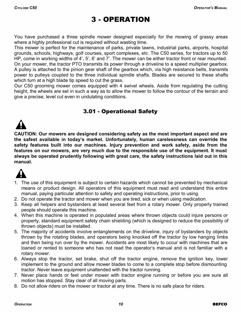
1. The use of this equipment is subject to certain hazards which cannot be prevented by mechanicalmeans or product design. All operators of this equipment must read and understand this entiremanual, paying particular attention to safety and operating instructions, prior to using.
2. Do not operate the tractor and mower when you are tired, sick or when using medication.3. Keep all helpers and bystanders at least several feet from a rotary mower. Only properly trained
people should operate this machine.4. When this machine is operated in populated areas where thrown objects could injure persons or
property, standard equipment safety chain shielding (which is designed to reduce the possibility ofthrown objects) must be installed.
5. The majority of accidents involve entanglements on the driveline, injury of bystanders by objectsthrown by the rotating blades, and operators being knocked off the tractor by low hanging limbsand then being run over by the mower. Accidents are most likely to occur with machines that areloaned or rented to someone who has not read the operator’s manual and is not familiar with arotary mower.
6. Always stop the tractor, set brake, shut off the tractor engine, remove the ignition key, lowerimplement to the ground and allow mower blades to come to a complete stop before dismountingtractor. Never leave equipment unattended with the tractor running.
7. Never place hands or feet under mower with tractor engine running or before you are sure allmotion has stopped. Stay clear of all moving parts.
8. Do not allow riders on the mower or tractor at any time. There is no safe place for riders.
OPERATION 10 BEFCO
CYCLONE C50 OPERATOR’S MANUAL
9. Do not operate unless all personnel, livestock and pets are several feet away to prevent injury bythrown objects.
10.Before backing up, disengage the mower and look behind carefully.11. Install and secure all guards and shields before starting or operating.12.Keep hands, feet, hair and clothing away from moving parts.13.This rotary mower is designed for use only on tractors with 540 rpm power take off.14.Never operate tractor and mower under trees with low hanging limbs. Operators can be knocked
off the tractor and then run over by the rotating blades.15.The rotating parts of this machine have been designed and tested for rugged use. However, they
could fail upon impact with heavy, solid objects such as steel guard rails and concrete abutments.Such impact could cause the broken objects to be thrown outward at very high velocities. Toreduce the possibility of property damage, serious injury, or even death, never allow the cuttingblades to contact such obstacles.
16.Frequently check mower blades. They should be sharp, free of nicks and cracks and securelyfastened.
17.Stop mower immediately upon striking an obstruction. Turn engine off, remove key, inspect andrepair any damage before resuming operation.
18.Stay alert for holes, rocks and roots in the terrain and other hidden hazards. Keep away fromdrop-offs.
19.Use extreme care and maintain minimum ground speed when transporting on hillside, over roughground and when operating close to ditches or fences. Be careful when turning sharp corners.
20.Reduce speed on slopes and sharp turns to minimize tipping or loss of control. Be careful whenchanging directions on slopes. Do not start or stop suddenly on slopes. Avoid operation on steepslopes.
21.When using a unit, a minimum 20% of tractor and equipment weight must be on tractor frontwheels. Without this weight, tractor could tip over, causing personal injury or death. The weightmay be attained with a front end loader, front wheel weights, ballast in tires or front tractorweights. When attaining a minimum 20% of tractor and equipment weight on the front wheels, youmust not exceed the ROPS weight certification. Weigh the tractor and equipment. Do not guessor estimate!
22. Inspect the entire machine periodically3. Look for loose fasteners, worn or broken parts, and leakyor loose fittings.
23.Use only the driveline supplied with the mower. Do not use it if it is missing any shield or safetyprotection.
24.Pass diagonally through sharp dips and avoid sharp drops to prevent “hanging up” tractor andmower.
25.Avoid sudden starts and stops while traveling up or downhill.26.Always cut down slopes; never across the face. Avoid operation on steep slopes. Slow down on
sharp turns and slopes to prevent tipping and or loss of control.
3.02 - Set Up
Notice to dealer: Pre-delivery setup and service including lubrication is the responsibility of theauthorized dealer. It is up to him to assure that the machine is in perfect condition and ready to beused. It is his responsibility to ensure that the customer is aware of all safety aspects and operationalprocedures for the mower. He must also fill out the Pre-Delivery Checklist4 prior to delivering themower.
OPERATION 11 BEFCO
CYCLONE C50 OPERATOR’S MANUAL
4 See Chapter 7 - Pre-Delivery Checklist.
3 See Chapter 4 - Maintenance.
CAUTION: Stand clear of bands when cutting as they could be under sufficient tension to
cause them to fly loose. Take care in removing bands and wire, they often have extremely
sharp edges and cut very easily.
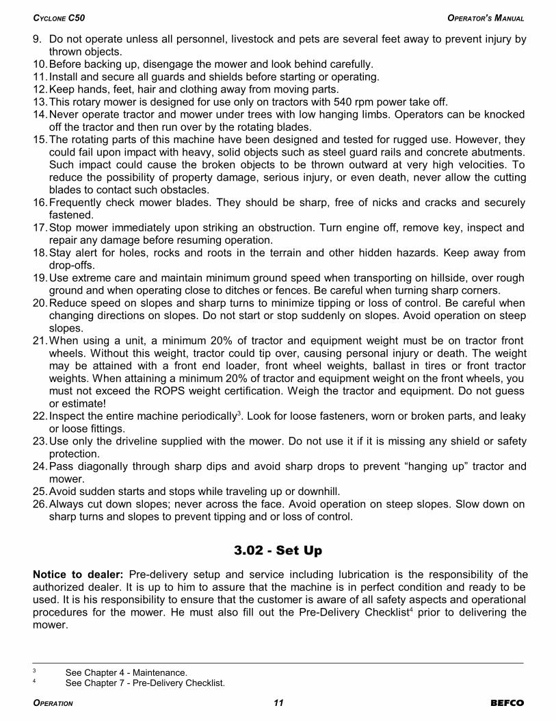
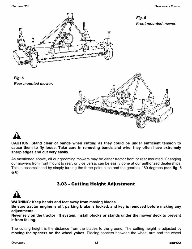
As mentioned above, all our grooming mowers may be either tractor front or rear mounted. Changingour mowers from front mount to rear, or vice versa, can be easily done at our authorized dealerships.This is accomplished by simply turning the three point hitch and the gearbox 180 degrees (see fig. 5& 6).
3.03 - Cutting Height Adjustment
WARNING: Keep hands and feet away from moving blades.
Be sure tractor engine is off, parking brake is locked, and key is removed before making any
adjustments.
Never rely on the tractor lift system. Install blocks or stands under the mower deck to prevent
it from falling.
The cutting height is the distance from the blades to the ground. The cutting height is adjusted bymoving the spacers on the wheel yokes. Placing spacers between the wheel arm and the wheel
OPERATION 12 BEFCO
CYCLONE C50 OPERATOR’S MANUAL
Fig. 5
Front mounted mower.
Fig. 6
Rear mounted mower.
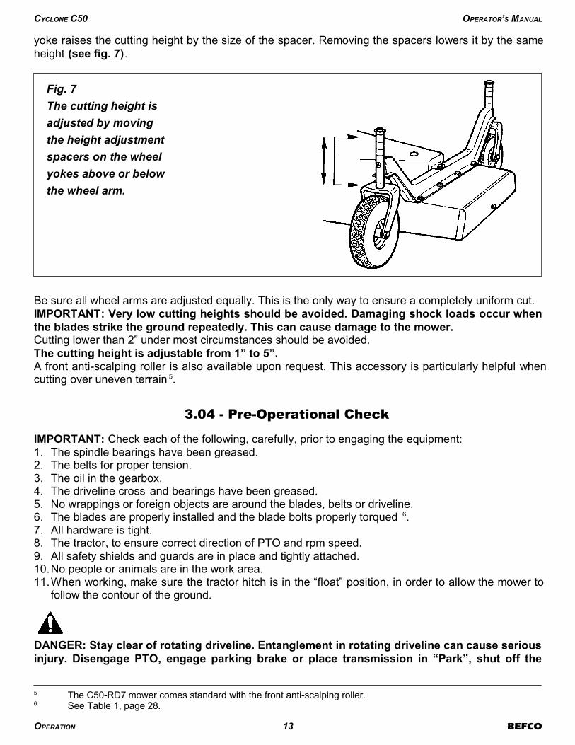
yoke raises the cutting height by the size of the spacer. Removing the spacers lowers it by the sameheight (see fig. 7).
Be sure all wheel arms are adjusted equally. This is the only way to ensure a completely uniform cut.IMPORTANT: Very low cutting heights should be avoided. Damaging shock loads occur when
the blades strike the ground repeatedly. This can cause damage to the mower. Cutting lower than 2” under most circumstances should be avoided.The cutting height is adjustable from 1” to 5”.A front anti-scalping roller is also available upon request. This accessory is particularly helpful whencutting over uneven terrain 5.
3.04 - Pre-Operational Check
IMPORTANT: Check each of the following, carefully, prior to engaging the equipment:1. The spindle bearings have been greased.2. The belts for proper tension.3. The oil in the gearbox.4. The driveline cross and bearings have been greased.5. No wrappings or foreign objects are around the blades, belts or driveline.6. The blades are properly installed and the blade bolts properly torqued 6.7. All hardware is tight.8. The tractor, to ensure correct direction of PTO and rpm speed.9. All safety shields and guards are in place and tightly attached.10.No people or animals are in the work area.11.When working, make sure the tractor hitch is in the “float” position, in order to allow the mower to
follow the contour of the ground.
DANGER: Stay clear of rotating driveline. Entanglement in rotating driveline can cause serious
injury. Disengage PTO, engage parking brake or place transmission in “Park”, shut off the
OPERATION 13 BEFCO
CYCLONE C50 OPERATOR’S MANUAL
6 See Table 1, page 28.
5 The C50-RD7 mower comes standard with the front anti-scalping roller.
Fig. 7
The cutting height is
adjusted by moving
the height adjustment
spacers on the wheel
yokes above or below
the wheel arm.
tractor and remove the key before working around hitch, attaching or detaching driveline,making adjustments, servicing or cleaning the machine.
3.05 - Attaching to the Tractor
Unit may be used on tractors ranging from 20 to 50 HP equipped with a standard PTO and category1 three point hitch 7. Never use this mower with tractors over 50 HP.
CAUTION: Check the tractor PTO rpm to ensure it is set at 540 and turns clockwise.
CAUTION: Always ensure that the tractor tire pressure is correct according to the tractor
operator’s manual.
DANGER: Failure to ensure a secure coupling of the implement to the tractor can cause injury
and damage to the implement or tractor.
To attach the mower to the tractor do the following: 1. Back the tractor up to the mower in order to slip the tractor hitch arms over the hitch pins welded
to the mower hitch arms. Turn off the tractor engine. Secure them in place with the lynch pins. 2. Adjust the tractor sway blocks or chains to remove all side movement.3. Attach the top link. Adjust tractor top link to allow the mower to follow the ground contour and yet
remain as level as possible when raised to transport position. 4. Install the shielded driveline to the tractor by first lining up the splines and depressing the snap
pin. Push the yoke onto the PTO shaft as far as it will go. Release the pin and pull back slowlyuntil the pin clicks in place. Repeat this operation on the implement end.
5. Attach the driveline chains to the tractor and to the mower to keep the driveline protection fromturning. The chains should not be too tight.
3.06 - Start Up
DANGER: The mower must always be lowered to the ground before starting tractor engine or
engaging PTO lever.
Lower mower to the ground with the tractor rock shaft control lever. With the engine idling, slowlyengage the PTO drive. Move the throttle lever until the PTO speed indicated on the mower isobtained.The mower is set for a PTO speed of 540 rpm.Shift the transmission to a slow speed gear and start forward, increase the ground speed by shiftingupward until the desired speed is obtained. Do not mow in reverse unless absolutely necessary andonly after careful observation of the area behind the mower.
OPERATION 14 BEFCO
CYCLONE C50 OPERATOR’S MANUAL
7 See Table 2, page 28.
CAUTION: Do not operate this mower at a PTO speed or direction of rotation other than that
shown on the mower. Serious damage can occur to the machine and/or the operator.
Before starting to mow, never forget that the operator is responsible for the following:1. Safe and correct driving of the tractor and mower.2. To learn precise safe operating procedures for both the tractor and the mower.3. To ensure all maintenance and lubrication has been performed on the mower.4. To have read and understood all safety aspects for the mower in the operator’s manual.5. To have read and understood all safety decals on the mower.6. Checking the condition of the blades. Worn or damaged blades should be changed before
starting8.7. Checking to ensure that the cutting edge is the leading edge of the blade 9.8. Checking that there is no wire, weed, grass or other material wrapped around blades.9. Checking to see if front weights need to be added to the tractor in order to maintain balance.10.Checking the tractor tires for the proper pressure in accordance with the tractor operator’s
manual.11.Checking that the PTO shield, belt shields and all other shielding are on the machine and
securely in place. 12.Making sure the proper attire is worn. Avoiding loose fitting clothing which can become entangled.
Wearing sturdy, tough-soled work shoes and protective equipment for eyes, hands, ears andhead. Never operate tractor or implements in bare feet, sandals or sneakers.
13.Checking area for stones, branches and other debris that might be thrown.14.Ensuring proper lighting is available, sunlight or good artificial lighting.
3.07 - Working Speed
The mowing speed depends on ground conditions, tractor HP, mowing height, and grass thickness.Only a test run will enable you to gauge the optimal working speed for your conditions. Under mostconditions a 3 to 8 mph ground speed is best. As a rule of thumb, and if the conditions permit, grassdispersion is increased by higher ground speeds. In order to obtain the best cut possible, always
OPERATION 15 BEFCO
CYCLONE C50 OPERATOR’S MANUAL
9 See Section 4.03 - Blade Maintenance.
8 See Section 4.03 - Blade Maintenance.
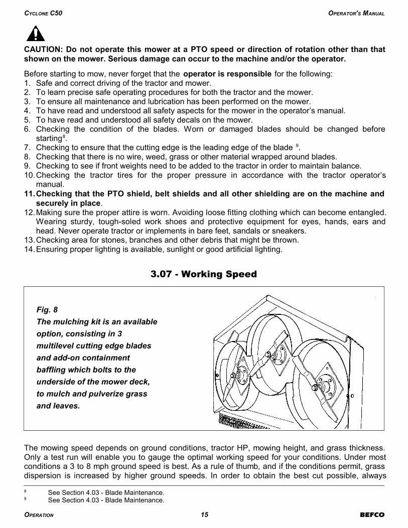
Fig. 8
The mulching kit is an available
option, consisting in 3
multilevel cutting edge blades
and add-on containment
baffling which bolts to the
underside of the mower deck,
to mulch and pulverize grass
and leaves.
keep the tractor rpm up to the speed indicated on the mower. When increasing or decreasingmowing ground speed, always use gear selection, not engine speed. This will maintain the constantmaximum blade speed necessary for a clean cut. The mulching kit is an option available for our mowers. This kit, containing 3 multilevel cutting edgeblades and add-on containment baffling which bolts to the underside of the mower deck, mulchesand pulverizes grass and leaves.Another benefit of the mulching kit is safety. In fact, the kit greatly reduces the possibility of thrownobjects. This is particularly important when mowing around schools, public parks and golf courses. Ifyou are using a mulching kit, you need to reduce your ground speed to under 2 mph (see fig. 8).
3.08 - Operating Techniques
All of the following factors are important in selecting the proper forward speed:1. Height of grass.2. Type of grass.3. Density of grass.4. Type of terrain.5. Grass condition, wet or dry.
This mower has been designed to cut grass with heights from 4” to 8”. It is recommended to avoidcutting grass taller than 10”. For the best results, try cutting the grass at least once per week duringgrowing season. Tall, dense grass should be cut at low speed, while thin medium grass can be cut ata faster ground speed. For cleaner cuts and efficient mowing, the blades must be kept sharp 10. Always operate PTO at 540 rpm. This is necessary to maintain proper blade speed and obtain aclean cut.Under certain conditions, tractor tires may roll some grass down and prevent it from being cut at thesame height as the surrounding area. If this occurs reduce the tractor ground speed but maintain a540 rpm engine speed. The lower ground speed will permit the grass to at least partially rebound.Under some conditions grass will not rebound enough to be cut evenly, resulting in an unevenappearance. In general, lower cutting height gives a more even cut with less tendency to leave tiretracks. If cut is still not satisfactory, cut the area twice.Mow extremely tall grass twice. On the first pass use a high cutting height. On the second passposition the mower at the desired height and, when practical, mow at a right angle in travel to the firstpass.Plan your pattern to travel straight forward whenever possible. It is better to cut grass more often,than too short. Short grass deteriorates rapidly in hot weather and invites weed growth duringgrowing season.If at any time the mower should jam resulting in belt slippage of 2 or more seconds, raise the mowerand continue for 2-3 minutes. This will allow the pulleys to cool and prolong belt life.
DANGER: The mower blades can throw objects hundreds of feet which could result in
personal or property damage.
Pick up all rocks and other debris before mowing.
Enter new areas carefully. Cut grass higher at first, allowing mower to clear hidden objects.
OPERATION 16 BEFCO
CYCLONE C50 OPERATOR’S MANUAL
10 See Sharpening Blades in Section 4.03 - Blade Maintenance.

CAUTION: For emergency reasons learn how to stop the tractor and mower quickly. On the
finishing mowers always disengage the PTO, lock parking brake, stop engine and allow the
mower blades to come to a complete stop before dismounting the tractor.
3.09 - Uneven Terrain
DANGER: Be careful of rollover when operating tractor and mower over uneven ground.
The following precautions should always be observed when working on uneven terrain:1. In extremely uneven terrain rear wheel weights, front tractor weights, and/or tire ballast should be
used to improve stability.2. Observe the type of terrain and develop a safe working pattern.3. Whenever traction or stability is doubtful, first test drive over the terrain with the PTO disengaged.4. Operate the implement up and down steep slopes, not across slopes, to prevent the tractor from
tipping. Avoid sudden stops and starts, and slow down before changing directions on a slope.5. Pass diagonally through sharp dips and avoid sharp drops to prevent hanging up the tractor and
implement.6. Slow down on sharp turns and slopes to prevent tipping or loss of control.7. Avoid tipping the mower while cutting.8. Watch for holes, roots or other hidden objects. Do not use near the edge of a gully, ditch or
stream bank.
An anti-scalping roller is recommended for uneven ground contours. The roller rides the nose
of the mower over a mound to help keep the nose from bulldozing or the blades from scalping
the ground.
3.10 - Removing Mower from the Tractor
CAUTION: Disengage tractor PTO. Set parking brake. Stop engine and remove key from
ignition. Disconnect mower driveline from tractor PTO shaft. Collapse driveline and store in
appropriate place. Disconnect three point linkage and carefully drive tractor away from
mower.
3.11 - Quick Hitch Adapter Assembly and Operation
Using a Quick Hitch system: The C50 series mowers can be used with a Quick Hitch system,allowing for quick and easy hookup, by installing an optional adapter. This optional adapter hasfloating yokes that will allow the mower to follow the contour of the ground.
WARNING: When using a Quick Hitch on a PTO driven implement always ensure there is the
proper driveline overlap prior to use. If there is not the minimum 6” driveline overlap do not
use and contact your nearest dealer to purchase a longer driveline.
OPERATION 17 BEFCO
CYCLONE C50 OPERATOR’S MANUAL

Quick Hitch Adapter assembly (see fig. 9):1. Remove lower hitch arms from grooming mower’s linking plates.2. Remove bolt M16x140 on top of the three point hitch of the grooming mower.3. Remove bolts M16x45 that hold the top hitch supports to the linking plates of the mower.4. Install the floating yokes of Quick Hitch Adapter assembly to the linking plates of the mower using
the hex bolts M16x65 and the stover nuts M16. Install the floating yokes in the same hole that thehitch pins were mounted. NOTE: When installing the quick hitch adapter on the C50-RD7, the
floating yokes need to be installed on the opposite side than the other models. Install the
left yoke on the right side and the right yoke on the left side of the mower (see fig. 10).5. For proper operation of the mower, ensure that the floating yokes are parallel to the ground.6. Install the floating top link to the top hitch arms using the bolt M16x110 and the stover nut M16.7. Install the A-frame support to the floating top link using the same bolt M16x140 that was
previously removed from the top of the three point hitch of the grooming mower and the stover nutM16.
8. Install the A-frame support to the floating yokes using the hex bolt M20x160 and the stover nutM20.
9. Loosen the bolts M16x45 that secure the top hitch arms to the rear support plates of the mower.Only loosen slightly. The arms must be able to move slightly up and down.
10.Tighten all hardware, ensuring all bolts and nuts have enough play to allow quick hitch adapter tomove up and down.
Quick Hitch Adapter operation:After completing assembly of the adapter, the tractor lift arms should be raised and locked in aposition so the floating yokes are horizontal.
CAUTION: Improper setup of the Quick Hitch Adapter can result in equipment damage. A
replacement driveline must generally be installed to prevent injury or equipment damage
when using the Quick Hitch Adapter.
OPERATION 18 BEFCO
CYCLONE C50 OPERATOR’S MANUAL
Fig. 9 - Quick Hitch Adapter assembly.

CAUTION: If the three point hitch of the tractor is set in the lowest position, the driveline may
bottom out against the Quick Hitch resulting in a bent driveline. If the mower is lifted after the
driveline has been bent, it may also damage the gearbox, mounting plates, and other
hardware.
OPERATION 19 BEFCO
CYCLONE C50 OPERATOR’S MANUAL
Fig. 10 - Quick Hitch Adapter floating yoke installation.
C50-RD7C50-RD4, RD5 & RD6

4 - MAINTENANCE
DANGER: Stop engine, lock parking brake and remove key before performing any service or
maintenance.
Never rely on the tractor lift system. Install blocks or stands under the mower deck to prevent
it from falling.
Always use personal protection devices, such as glasses or gloves when performing
maintenance.
Keep fingers out of slots to prevent injury.
4.01 - Maintenance Safety
1. Good maintenance is your responsibility.2. Keep service area clean and dry. Be sure electrical outlets and tools are properly grounded. Use
adequate light for the job at hand.3. Make sure there is plenty of ventilation. Never operate the engine of the towing vehicle in a closed
building. The exhaust fumes may cause asphyxiation.4. Make no repair or adjustments with the tractor engine running. Before working on the machine,
disengage the PTO, shut off the engine, set the brakes, and remove the ignition key.5. Be certain all moving parts on attachment have come to a complete stop before attempting to
perform maintenance.6. Never work under equipment unless it is blocked securely.7. Always use personal protection devices such as eye, hand and hearing protectors, when
performing any service or maintenance.8. Frequently check mower blades. They should be sharp, free of nicks and cracks and securely
fastened.9. Periodically tighten all bolts, nuts and screws and check that all cotter pins are properly installed
to ensure unit is in a safe condition.10.When completing a maintenance or service function, make sure all safety shields and devices are
installed before placing unit in service.11.Do not attempt to mount a tire unless you have the proper equipment and experience to do the
job.12. Inflating or servicing tires can be dangerous. Whenever possible, trained personnel should be
called to service and/or mount tires.13.After servicing, be sure all tools, parts and service equipment are removed.14.Never replace hex bolts with less than grade five bolts unless otherwise specified, i.e. shear
bolts11.15.Where replacement parts are necessary for periodic maintenance and servicing, genuine
replacement parts must be used to restore your equipment to original specifications. Thecompany will not claim responsibility for use of unapproved parts and/or accessories and otherdamages as a result of their use.
MAINTENANCE 20 BEFCO
CYCLONE C50 OPERATOR’S MANUAL
11 Refer to Table 1 - Torque Specifications, page 28.
16.Unauthorized modifications to the machine may impair the function and/or safety of the machineand reduce its life. If equipment has been altered in any way from original design, themanufacturer does not accept any liability for injury or warranty.
4.02 - Service
The accompanying illustrations show lubrication points. The chart gives the frequency of lubricationin hours, based on normal operating conditions. Severe or unusual conditions may require morefrequent lubrication.Use a good quality SAE multipurpose type grease for all locations shown. Be sure to clean fittingsthoroughly before using grease gun.Use 90 wt. gear oil in gearbox.
Hourly: 1. Check the condition of mower blades for nicks or dull edges. Sharpen if necessary.2. Replace bent or damaged blades 12.3. Also check blades for damage after hitting an obstruction. 4. Clean foreign material from mower deck and belt area.
Every 8 hours:
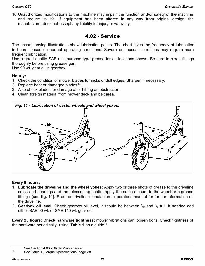
1. Lubricate the driveline and the wheel yokes: Apply two or three shots of grease to the drivelinecross and bearings and the telescoping shafts; apply the same amount to the wheel arm greasefittings (see fig. 11). See the driveline manufacturer operator’s manual for further information onthe driveline.
2. Gearbox oil level: Check gearbox oil level, it should be between 1/2 and 2/3 full. If needed addeither SAE 90 wt. or SAE 140 wt. gear oil.
Every 25 hours: Check hardware tightness; mower vibrations can loosen bolts. Check tightness ofthe hardware periodically, using Table 1 as a guide13.
MAINTENANCE 21 BEFCO
CYCLONE C50 OPERATOR’S MANUAL
13 See Table 1, Torque Specifications, page 28.
12 See Section 4.03 - Blade Maintenance.
Fig. 11 - Lubrication of caster wheels and wheel yokes.

Every 50 hours:
1. Lubricate the three spindles with two or three shots of multipurpose grease (see fig. 12). The topgrease fittings are easily accessible from the top of the deck by simply removing the plastic dustguards.
2. Check belt tension14.
4.03 - Blade Maintenance
WARNING: To avoid possible injury always wear proper eye and hand protection when
servicing mower blade.
In order for the mower to work properly, and to always obtain a precision cut with lower HPrequirements thus keeping cost down, proper blade maintenance is important.Blades must be kept sharp, at their original length and corners maintained. A blade must be replacedif, due to wear or damage, its original shape has been distorted.
Installing or removing bladesIf the mower blades need to be installed, do the following:1. The blade turns in a counter clockwise direction when viewed from the bottom of the deck. The
cutting edge must be towards the direction of rotation. The lift wing of the blades is closest to thedeck and the cutting edge away from it (see fig. 13).
2. Install the cup washer (see fig. 13) over the blade bolt and secure the blade in place as describedabove.
3. With a wrench, block the spindle and tighten the bolt to 103 lb. ft. (see fig. 14).4. To remove the blades reverse the procedure.
WARNING: Do not substitute blades or any bolt for the blade retaining bolt. Company blades
and blade retaining bolts are specially made for this application. Using non original parts can
effect the quality of cut and may also cause damage to the mower.
MAINTENANCE 22 BEFCO
CYCLONE C50 OPERATOR’S MANUAL
14 See Section 4.04 - Belt Tension.
Fig. 12
Lubrication of the spindle shafts easily
accessible from the top of the deck.
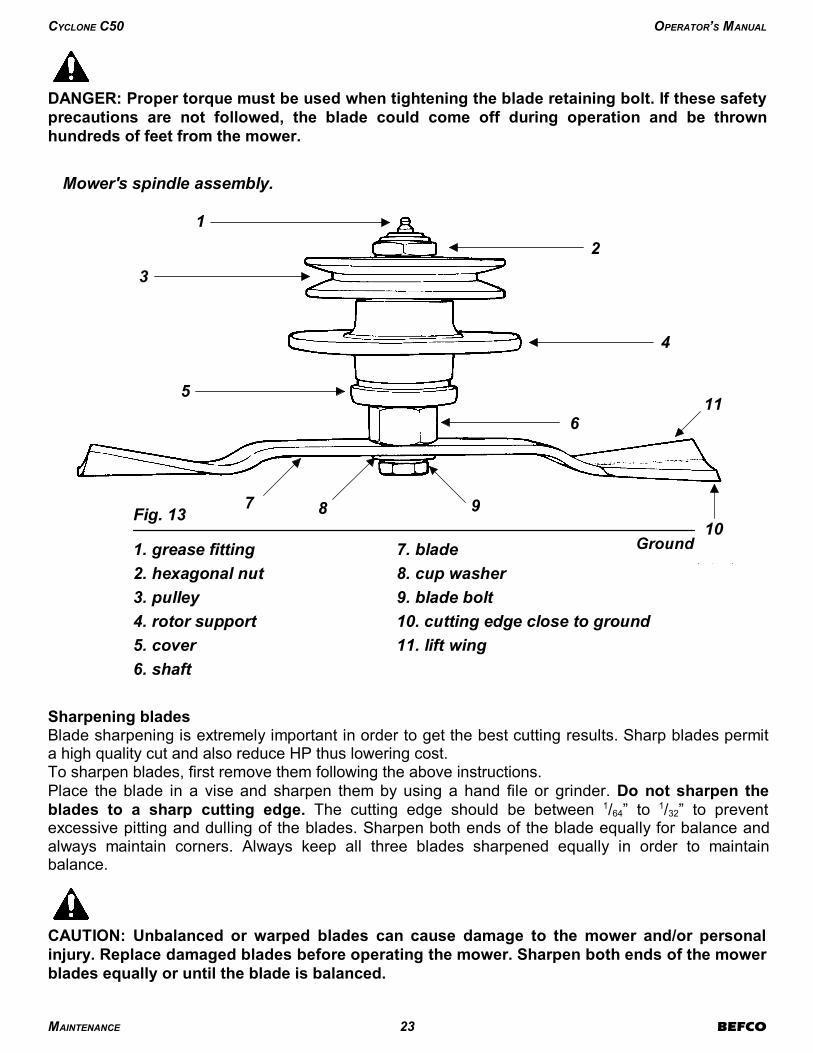
DANGER: Proper torque must be used when tightening the blade retaining bolt. If these safety
precautions are not followed, the blade could come off during operation and be thrown
hundreds of feet from the mower.
Sharpening bladesBlade sharpening is extremely important in order to get the best cutting results. Sharp blades permita high quality cut and also reduce HP thus lowering cost.To sharpen blades, first remove them following the above instructions. Place the blade in a vise and sharpen them by using a hand file or grinder. Do not sharpen theblades to a sharp cutting edge. The cutting edge should be between 1/64” to 1/32” to preventexcessive pitting and dulling of the blades. Sharpen both ends of the blade equally for balance andalways maintain corners. Always keep all three blades sharpened equally in order to maintainbalance.
CAUTION: Unbalanced or warped blades can cause damage to the mower and/or personal
injury. Replace damaged blades before operating the mower. Sharpen both ends of the mower
blades equally or until the blade is balanced.
MAINTENANCE 23 BEFCO
CYCLONE C50 OPERATOR’S MANUAL
Fig. 13
1
3
5
7 8 9
2
4
6
10
11
1. grease fitting
2. hexagonal nut
3. pulley
4. rotor support
5. cover
6. shaft
7. blade
8. cup washer
9. blade bolt
10. cutting edge close to ground
11. lift wing
Ground
Mower's spindle assembly.
4.04 - Belt Tension
Belt tension control
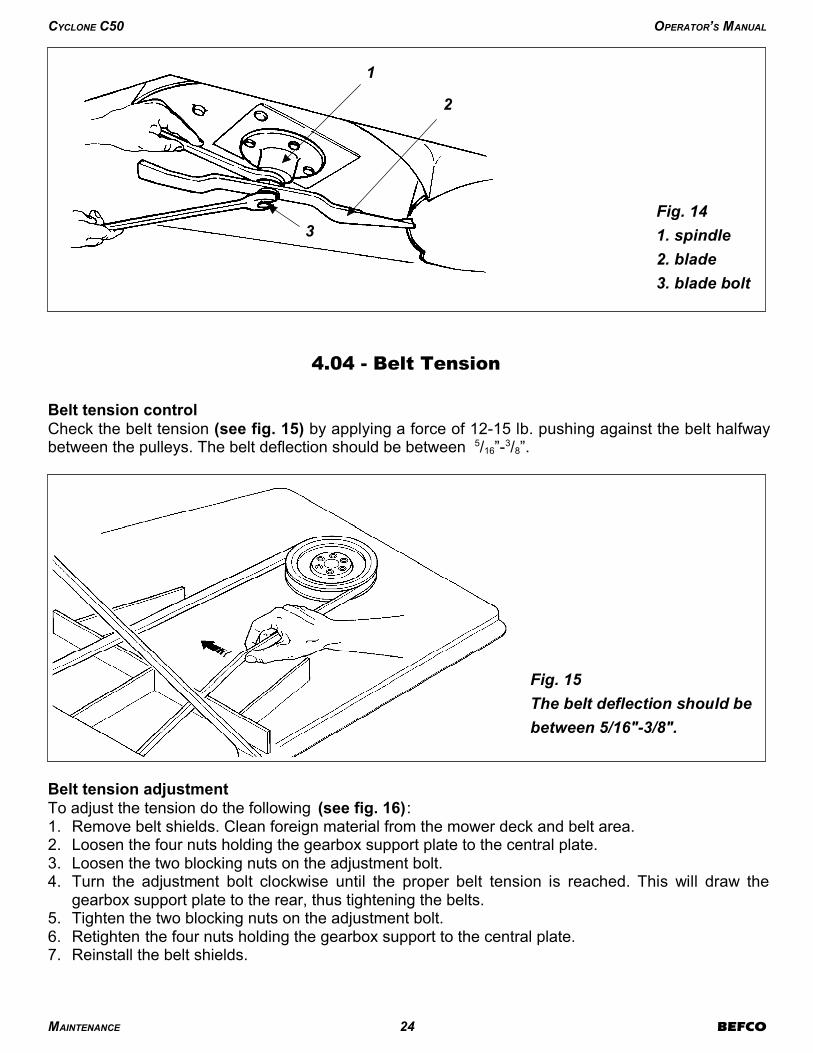
Check the belt tension (see fig. 15) by applying a force of 12-15 lb. pushing against the belt halfwaybetween the pulleys. The belt deflection should be between 5/16”-3/8”.
Belt tension adjustment
To adjust the tension do the following (see fig. 16):1. Remove belt shields. Clean foreign material from the mower deck and belt area.2. Loosen the four nuts holding the gearbox support plate to the central plate.3. Loosen the two blocking nuts on the adjustment bolt.4. Turn the adjustment bolt clockwise until the proper belt tension is reached. This will draw the
gearbox support plate to the rear, thus tightening the belts. 5. Tighten the two blocking nuts on the adjustment bolt.6. Retighten the four nuts holding the gearbox support to the central plate.7. Reinstall the belt shields.
MAINTENANCE 24 BEFCO
CYCLONE C50 OPERATOR’S MANUAL
1
2
3
Fig. 14
1. spindle
2. blade
3. blade bolt
Fig. 15
The belt deflection should be
between 5/16"-3/8".
4.05 - Belt Replacement
If the belts have been stretched or damaged to the point where the proper tension cannot beobtained they must be changed.
To replace belts do the following:1. Remove belt shields. Clean foreign material from the mower deck and belt area.2. Loosen the four nuts holding the gearbox support plate to the central plate.3. Loosen the two blocking nuts on the adjustment bolt.4. Turn the adjustment bolt counter clockwise, pushing the gearbox support plate forward until all
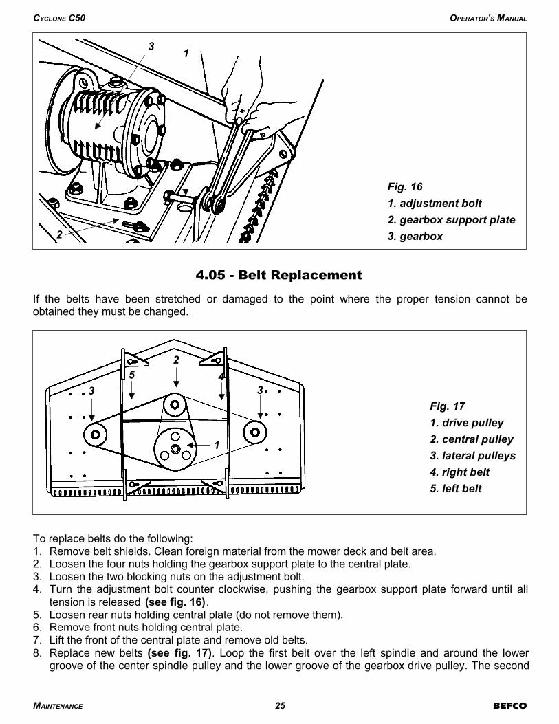
tension is released (see fig. 16).5. Loosen rear nuts holding central plate (do not remove them).6. Remove front nuts holding central plate.7. Lift the front of the central plate and remove old belts.8. Replace new belts (see fig. 17). Loop the first belt over the left spindle and around the lower
groove of the center spindle pulley and the lower groove of the gearbox drive pulley. The second
MAINTENANCE 25 BEFCO
CYCLONE C50 OPERATOR’S MANUAL
Fig. 16
1
2
3
1. adjustment bolt
2. gearbox support plate
3. gearbox
Fig. 17
1. drive pulley
2. central pulley
3. lateral pulleys
4. right belt
5. left belt
1
2
4
33
5

belt connects the upper grooves of the center spindle pulley and the gearbox drive pulley with theright spindle pulley.
9. Lower central plate.10.Replace front nuts. Tighten front and rear nuts holding down central plate.11.Turn the adjustment bolt clockwise until the proper belt tension is reached. This will draw the
gearbox support plate to the rear, thus tightening the belts.12.Tighten the two blocking nuts on the adjustment bolt.13.Retighten the four nuts holding the gearbox support to the central plate and replace the belt
shields.
4.06 - Driveline
DANGER: Only use the original driveline supplied with this machine and always with the
safety shielding. Carefully read and file away the driveline operator’s manual supplied by the
manufacturer. The following does not substitute the information found in the driveline manual.
IMPORTANT: Always check driveline length during initial setup and when connecting to a differenttractor.
In the collapsed position the driveline should be approximately 2” from bottoming out to preventpossible damage to the tractor or implement. When the driveline is in the maximum extendedposition, the ideal minimum overlap of the two halves should be approximately 6” (see fig. 18).
If determined that the driveline is too long , follow these procedures to adjust the length:1. Separate the two driveline halves. Connect one half to the tractor PTO and the other half to the
mower.2. Raise and lower the mower with the 3 point hitch to find the position where the driveline is
shortest. Hold the half shafts side by side and mark the desired length on the outer female tubeguard leaving a 1½” gap between the end of the guard tube and bell guard.
3. Cut off both guard tubes the same amount as marked in step 2.4. Shorten both drive tubes the same amount as guard tubes.5. De-burr and clean filings from drive tubes and apply grease to outside of inner telescoping tube.
MAINTENANCE 26 BEFCO
CYCLONE C50 OPERATOR’S MANUAL
Fig. 18
MAX.
MIN.
min. 6"
min. 2"
6. Reassemble the driveline halves and connect to tractor and mower. Raise and lower mower againto be sure driveline does not bottom out in its shortest position and has a minimum overlap of 6”in the longest position.
7. Install both driveline safety chains. One should be hooked in a hole on the outer driveline yokeshield and to the tractor to restrict outer shield rotation. The second one should be hooked in ahole on the inner driveline yoke shield and to the implement to restrict inner shield rotation.
If determined that the driveline is too short for your tractor, contact your local dealer.
CAUTION: Always work with the driveline as straight as possible. This will prolong its life and
that of its components. It is advised not to work at an angle greater than 15 degrees.
4.07 - Transport
Before raising the mower for transport, the tractor top link must be adjusted so when lifted, the rear ofthe machine is higher than the front (the mower’s nose is tilted downward). To do this, shorten thetractor top link until the top hitch plate is locked forward and no longer able to pivot. This will keep themower locked in position and minimize the shaking and bouncing during transport which can damagethe hitch or frame.
CAUTION: Make sure PTO is disengaged and blades have stopped turning before raising
mower to full transport position. Do not tow tractor and mower behind other vehicles. Use a
properly equipped trailer with heavy tie-downs for towing operations.
Before transporting:1. Always select a safe ground speed that is appropriate for the terrain.2. Beware of traffic on public roads. Install a SMV (Slow Moving Vehicle) sign when traveling on
roads or streets. Comply with all federal, state and local laws.3. Reduce ground speed when turning and take care that the implement does not strike obstacles
such as trees, fences or buildings.4. Always disengage PTO before raising the implement to transport position.5. When raising the mower be sure the PTO driveline does not hit either the mower or the tractor.6. During transport the mower should not be lifted over 14”-16” from the ground.
MAINTENANCE 27 BEFCO
CYCLONE C50 OPERATOR’S MANUAL

TABLE 1 - TORQUE SPECIFICATIONS
When using lock washers with nuts, increase torque values by 5%.
35574823219429749781326121-1/2”2607353518302482113115344M36
3161428619492643869117961-1/2”165922501180160073810002M30
27123677167322687461011121-3/8”14992033104714206689063.5M30
238232301469199265588861-3/8”1176159482511195307192M27
2012272812411682553750121-1/4”1103149677410504846563M27
181724631120151950067771-1/4”80810955677693604882M24
144519588911208397539121-1/8”75010175267143274443M24
12881746794107735448071-1/8”6448734526132813811.5M22
9951348704955273371121”5958074185672543442.5M22
909123264487325033981”4766463354542122881.5M20
668906473642184249147/8”4375923064151892562.5M20
60682243058216722697/8”3434652413271502031.5M18
420569297403192261163/4”3274432293111451962M18
376509266361172233103/4”3104212182951331812.5M18
240325170230110149185/8”2363201612181041411.5M16
21228715020397132115/8”223302152206971312M16
17123212116479106189/16” 15420910514269941.5M14
1542081091477095129/16” 1441959813362842M14
120163851155575201/2”98133669044591.25M12
106144751024866131/2”94128648741561.5M12
7810655753648207/16”91123628440541.75M12
709549673243147/16”5878395326351M10
496735472331243/8”5575385124331.25M10
445931422027163/8”5271354823311.5M10
273719261317245/16”2838192613171M8
253317241115185/16”2736182512161.25M8
1419101368281/4”1115710461M6
121681157201/4”7946340.8M5
ft-lbN.mft-lbN.mft-lbN.mThread inch
tpi
Bolt size
inchft-lbN.mft-lbN.mft-lbN.m
Thread
mm
Bolt size
mm
Grade 8Grade 5Grade 2
Inch (SAE) treaded
bolts head marking
Class 10.9Class 8.8Class 5.8
Metric (ISO)treaded bolts head
marking
TABLE 2 - C50 GROOMING MOWERS - TECHNICAL FEATURES
ASAE 3rd cat.4-11”x4” AT
4-10”x3.2” HT 2 SPBX1”-5”316,3382,195
674690
86”84”20-50C50-RD7AC50-RD7H
ASAE 3rd cat.4-11”x4” AT
4-10”x3.2” HT 2 SPBX1”-5”316,7322,605
584600
74”72”20-50C50-RD6AC50-RD6H
ASAE 3rd cat.4-11”x4” AT
4-10”x3.2” HT 2 SPBX1”-5”316,9293,210
534550
62”60”20-50C50-RD5AC50-RD5H
ASAE 3rd cat.4-11”x4” AT
4-10”x3.2” HT2 SPBX1”-5”315,1573,475
513529
51”48”20-50C50-RD4AC50-RD4H
Driveline1 3/8”
# of wheels &size
# of belts& type
Cuttingheight
# ofblades
Bladestip speed
ft/min
Rotorrpm/min
Weightlb.
Overallwidth
Workingwidth
HPModel
Series C50, Rear discharge, for tractors up to 50 HP, PTO 540 rpm, 3 point hitch cat. 1
MAINTENANCE 28 BEFCO
CYCLONE C50 OPERATOR’S MANUAL
5 - REPAIR PROCEDURES
CAUTION: All repair procedures must be done by authorized dealerships. It is not
recommended that untrained individuals perform any repair work. The following operationsare detailed for qualified personnel only.
5.01 - Gearbox
To remove the gearbox do the following:1. Remove the belt guards.2. Loosen the nuts holding the gearbox support plate (see fig. 16).3. Loosen the nut and turn the bolt in order to push the gearbox forward and release tension on the
belts (see fig. 16).4. Remove the belts15.5. Remove the nuts holding the central plate to the frame.6. Remove the nut holding the pulley to the gearbox pinion shaft. Remove the pulley. 7. Unbolt the nuts holding the gearbox support plate to the central plate (see fig. 16). Remove
gearbox and gearbox support plate.8. Unbolt the nuts holding the gearbox to the gearbox support plate. Remove the gearbox.
If it is necessary to replace any part on the inside of the gearbox, it is important to replace oil seals orgaskets to ensure a tight fit when reassembling.
To replace the gearbox, follow the above instructions in reverse order.
5.02 - Blade Spindle
To remove a blade spindle do the following:1. Remove the belts16.2. Remove the nut holding the pulley to the spindle shaft (see fig. 13). 3. Remove the blades17.4. Unbolt the bolts holding the rotor support to the mower deck.5. If necessary remove and replace the bearings from the rotor using presses or extractors.6. Reassemble in reverse order ensuring that the nut securing the top pulley (see fig. 13) is
tightened to 118 lb.ft.
5.03 - Suggested Spare Parts
It is suggested that the following spare parts be kept on hand for the mower at all times to prevent aminor problem from delaying work.
REPAIR PROCEDURES 29 BEFCO
CYCLONE C50 OPERATOR’S MANUAL
17 See Section 4.03 - Blade Maintenance.
16 See Section 4.05 - Belt Replacement.
15 See Section 4.05 - Belt Replacement.
2Belts
3Washers
3Blade bolts
3Blades
QuantityDescription
5.04 - Storage
After seasonal use it is important to perform the following for prolonged storage:1. Wash the mower carefully.2. Inspect the mower and replace worn or damaged parts.3. Tighten all hardware.4. Grease all areas indicated under Maintenance 18.5. Loosen the belts if the mower is to be stored for an extended length of time. 6. Cover the mower from the elements in order to have it in perfect condition for the start of the next
season.
REPAIR PROCEDURES 30 BEFCO
CYCLONE C50 OPERATOR’S MANUAL
18 See Chapter 4 - Maintenance.

6 - TROUBLESHOOTING
WARNING: Be sure tractor engine is off, parking brake is locked, and key is removed before
making any adjustments.
Increase ground speed.Increase tractor rpm, check engine and PTOspeeds.
Ground speed too low.Tractor rpm too slow.
Cut grass windrows.
Allow grass to dry.Maintain engine speed and shift to lower gear.
Sharpen blade. See Blades Maintenancesection.Change blades.
Too wet to mow.Blades cannot cut grasspressed down by wheels.Dull blades.
Blades worn down, preventingoverlap.
Streaking conditionsin swath.
Check belt size.See Replacing Belts section.
Wrong belt size.Installed belts incorrectly.
Belts are tight wheninstalling.
Allow grass to dry.Raise mower, shift to lower gear, make twopasses over grass. Mow grass high 1st pass,2nd pass cut to desired height.Increase tractor rpm, check engine and PTOspeeds.
Wet grass.Grass too high.
Tractor rpm too slow.
Grass build up at exit.
Tighten belts.Belts slipping.Belt squeal.
Remove object.Replace belts.
Object wrapped around blade.Belts damaged.
Mower vibrates.
Tighten belt.Remove object.Clean pulleys.
Lack of tension.Object clogging mower.Debris in pulleys.
Belt slippage.
Blade should turn CCW when you face deckbottom. See Blades Maintenance section.
Direction of blades is wrong.Blades turning but notcutting.
Check washer location at all 3 spindles.
Shift to lower gear.Sharpen blades.Adjust wheel position.
Cup washer not betweenblade and bolt.Ground speed too fast.Blades need sharpening.Caster wheels uneven.
Uneven cutting.
SOLUTIONPOSSIBLE CAUSEPROBLEM
TROUBLESHOOTING 31 BEFCO
CYCLONE C50 OPERATOR’S MANUAL
7 - PRE-DELIVERY CHECKLIST
To the dealer: Inspect the machine thoroughly after assembly to assure it is functioning
properly before delivering it to the customer. The following checklist is a reminder of points to
cover. Check off each item as it is found satisfactory or after proper adjustment is made.
� Gearbox oil level.� Guards and shield properly fastened.� Lubrication of grease fittings.� All hardware properly tightened.� All decals properly located and readable (see fig. 4).� Blades properly installed, blade bolts and nuts tightened.� Overall condition (touch up scratches, clean and polish).� Test run, check for excessive vibration or overheating of bearings.� Operator’s Manual.
Review the Operator’s Manual with the customer. Explain the following:
� Warranty.� Safe operation and service.� Correct machine installation and operation.� Daily and periodic lubrication, maintenance and inspections.� Troubleshooting.� Operational procedures and storage.� Parts and service.� Fill out the Pre-Delivery Checklist and Warranty Registration form.� Give customer the Operator’s Manual and encourage the customer to read the manual carefully.
IMPORTANT: Warranty is not valid unless Pre-Delivery Checklist and Warranty Registration
form in Operator’s Manual is completed in detail and mailed to the Company.
Model Number: __________ Serial Number: __________
Delivery Date: __________ Dealer’s Signature: __________
PRE-DELIVERY CHECKLIST 32 BEFCO
CYCLONE C50 OPERATOR’S MANUAL
8 - WARRANTY
BEFCO’s responsibility will be limited to substitution of the acknowledged defective merchandise tothe same place of delivery as the previous one was supplied.
1. LIMITED WARRANTYBEFCO, Inc. herein referred to as the Company, warrants its machines and related accessories,hereafter referred to as the Machine, to be free from defects in material and workmanship, for aperiod of twelve (12) months from the date of invoice to the first registered owner; this limitedwarranty does not apply to common wear items and excludes belts, shear pins, oil, grease, tires,tubes, hydraulic hoses, knives and PTO shafts.Labor will be reimbursed at $40.00 per hour based on BEFCO’s time schedule.Cost of transport to the servicing dealer is the responsibility of the customer.Warranty coverage shall not be transferable from the first owner to any subsequent owner.
2. DISCLAIMER OF ALL OTHER WARRANTIES AND REMEDIES
Neither the Company nor any company affiliated with the Company makes any warranties,
representations or promises, expressed or implied, as to the quality, performance or
application of its products other than those set forth herein and does not make any implied
warranty of merchantability or fitness.
The only remedies the purchaser has in connection with the breach, or performance of any
warranty on the Company’s Machine are those set forth herein. In no event will the dealer, the
Company, or any company affiliated with the Company, be liable for:
a. Injuries or damages of any kind or nature, direct, consequential or contingent to person
or property.
b. Any expenses incurred by the owner to repair, replace or rework any allegedly defective
item.
c. Any loss, cost, forfeiture or damages (including loss of profits; loss of crops; loss
because of delay in field operations; any expenses or loss incurred for labor, supplies,
substitute machine rental; liabilities of the owner to its customers or third persons; and
all other consequential damages, losses, liabilities or damages for any other reasons)
whether direct or indirect, and whether or not resulting from or contributed to by the
default or negligence of the Company, its agents, employees and subcontractors which
might be claimed as a result of the use or failure of the equipment delivered.
The Company’s liability based on this limited warranty or any other applicable laws shall be
limited to replacement or refund of the purchase price of the product.
The limited warranty extended herein gives you specific rights and you may also have other
rights which vary from state to state. Neither the dealer nor the Company personnel has the
authority to make any representation or to modify the terms and limitations of this warranty in
any way.
Other than the limited warranty extended hereby there is no other expressed warranty in
connection with the design, safety or use of any of the Company’s products except as to title.
All implied warranties are expressly disclaimed pursuant to the terms of this warranty.
3. CUSTOM WORKIf the Machine is used for commercial purposes such as custom work, the period warranted for theMachine is limited to six (6) months from the date of delivery to the first registered owner and doesnot cover any labor charges incurred.
WARRANTY 33 BEFCO
CYCLONE C50 OPERATOR’S MANUAL

4. RENTALIf the Machine is used for rental purposes the period warranted for the Machine is limited to thirty (30)days from the date of delivery to the first registered owner and does not cover any labor chargesincurred.
5. REGISTRATIONIn order to qualify for coverage on this limited warranty, the product and name of the originalpurchaser must be registered with the Company by a completed Machine Pre-Delivery Checklist andWarranty Registration along with a copy of the dealer’s invoice to the first registered owner to theCompany within fourteen (14) days after the date of delivery to the original purchaser.
6. WARRANTY SERVICEWarranty Service must be performed by a dealer authorized by BEFCO. If the warranty servicerequested is approved, the owner shall pay only for labor beyond the rate allowed, for overtime labor,and for any mileage charge for transporting the equipment to and from the dealer’s shop. It isassumed that the dealer has the appropriate general and special tools to service the Machine. Timerequired for replacement of knives, oil, grease and to remove excessive dirt from the Machine is notsubject to reimbursement by the Company. The owner is required to clean the Machine beforepresenting it to the dealer for service work. The Machine must be delivered within thirty (30) daysafter failure date by the owner to the dealer to be eligible for warranty consideration.
7. UNAPPROVED SERVICE OR MODIFICATIONAll obligations of the Company under this limited warranty shall be terminated if:
a. Proper service and operation instructions as outlined in the Operator’s Manual and on theinstruction sticker on the Machine, are not followed.
b. The Machine is modified or altered in any way not approved by the Company.c. The Company does not receive a copy of the dealers invoice to the first registered owner
within fourteen (14) days from the date of delivery.d. The Company has not been paid in full, by the dealer, for the Machine.
8. ACCIDENTS AND NORMAL MAINTENANCEThis limited warranty covers defective material and workmanship. It does not cover depreciation ordamage caused by normal wear, accidents, improper maintenance, improper protection or improperuse. The costs of normal maintenance or repairs for accidents or improper use, and related labor willbe borne by the owner.
9. REPLACEMENT PARTSBEFCO, Inc. warrants replacement parts to be free from defect in material and workmanship for aperiod of thirty (30) days from the date of delivery to the original purchaser.
WARRANTY 34 BEFCO
CYCLONE C50 OPERATOR’S MANUAL

WARRANTY REGISTRATION
BEFCO, Inc.
P.O. Box 6036
Rocky Mount, NC 27802-6036 Tel: (252) 977.9920 - Fax: (252) 977.9718
Model # Serial #
PhoneDate of delivery Invoice #
Town State ZipTown State Zip
StreetStreet Country
Retail CustomerDealer Acct. #
Customer’s Signature: Dealer’s Signature:
Date: Date:
Inspected by:
Tractor make: Model: ; HP Type of operation: Private homeowner,Landscaping, Commercial maintenance,Golf Course, Municipality, Turf Farm,other: Approximate number of acres machine willbe used on annually:
I hereby acknowledge that:I have received and accepted delivery ofthe machine described.The equipment was checked thoroughlyfor loose or missing parts and has beenadjusted in accordance with thePre-Delivery Checklist.I have read and understand the nature andextent of the warranty and understandclearly that there were and are no otherrepresentations of warranties eitherexpressed or implied, made by anyone. Ihave been advised on proper operation,maintenance and lubrication procedure ofthis equipment.I have been instructed on and dounderstand the application, limitation andcapacities this equipment was designedand recommended for, all as described inthe Operator’s Manual and literaturepublished by the Company.
Pre-Delivery Checklist:
� Oil in gearbox. � Greased fittings. � Safety guards in place.� All hardware tight. � Bolts torqued correctly.� Attached unit to tractor. Yes/No.� Field adjusted. Yes/No. � Test run. Dry/Infield.� Safety decals.� Operator’s Manual.
The machine described above, had beenprepared for delivery according to thePre-Delivery Checklist and the Customerhas been instructed in its care andoperation and the condition of warranty.
This registration along with a copy of the invoice must be sent to BEFCO, Inc.
within 14 days of date of purchase.
f
Cut along this line
Sender:
Fold here
BEFCO, Inc.
Warranty Department
P.O. Box 6036
Rocky Mount, NC 27802-6036
Place stamp
here

BEFCO®
Parts Manual
CYCLONE
Three Spindle Grooming Mower
C50-RD4, C50-RD5, C50-RD6, C50-RD7
Parts Manual 07/2009C50-SD4, SD5, SD6
C50-RD4, RD5, RD6, RD7 Ver. N
BEFCO C50-RD4, RD5, RD6, RD7 (US)Printed on July 16, 2009
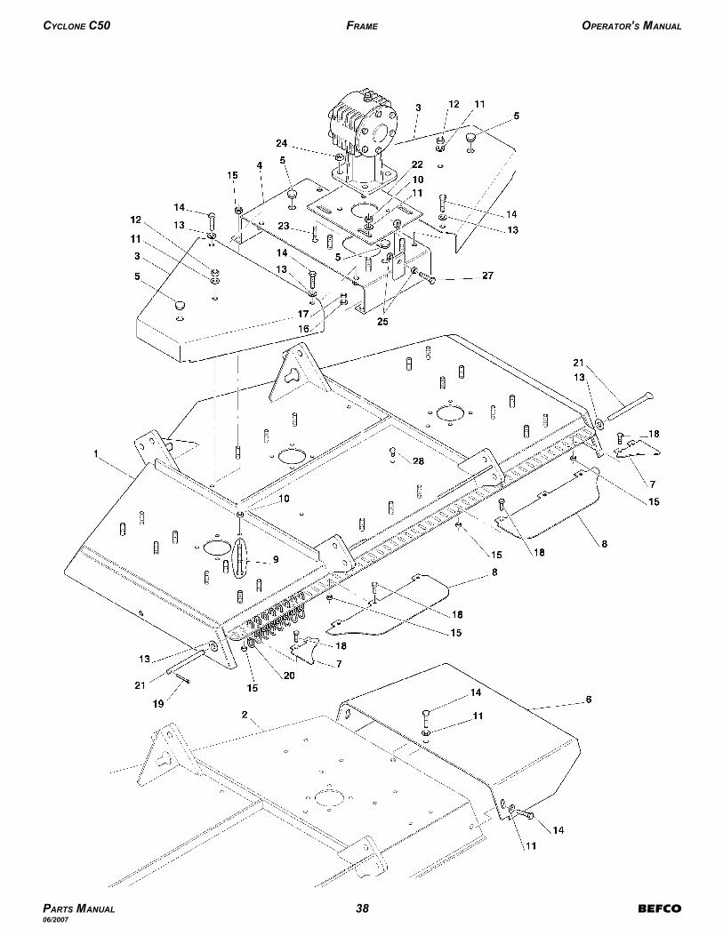
CYCLONE C50 FRAME OPERATOR’S MANUAL
PARTS MANUAL 38 BEFCO06/2007
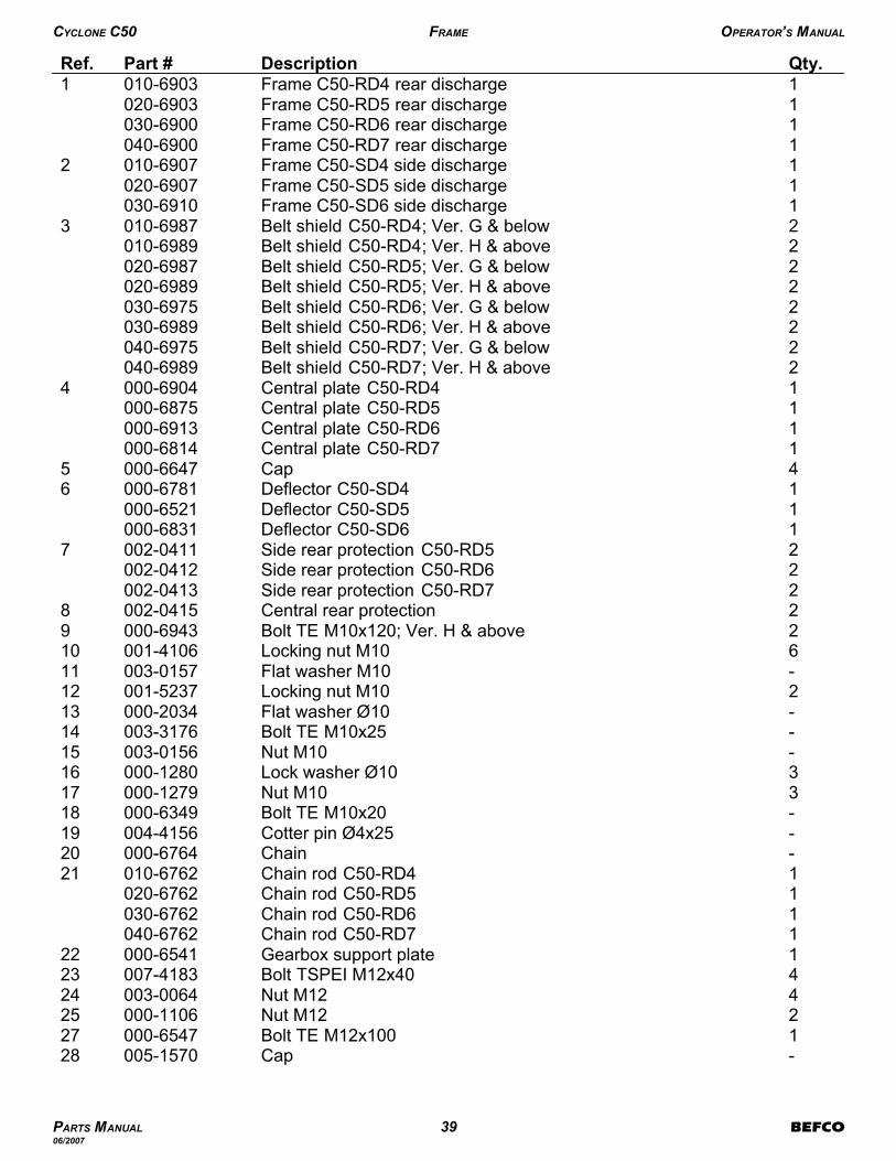
-Cap005-1570281Bolt TE M12x100000-6547272Nut M12000-1106254Nut M12003-0064244Bolt TSPEI M12x40007-4183231Gearbox support plate000-6541221Chain rod C50-RD7040-67621Chain rod C50-RD6030-67621Chain rod C50-RD5020-67621Chain rod C50-RD4010-676221- Chain000-676420-Cotter pin Ø4x25004-415619-Bolt TE M10x20000-6349183Nut M10000-1279173Lock washer Ø10000-128016-Nut M10003-0156 15-Bolt TE M10x25003-3176 14-Flat washer Ø10000-2034132Locking nut M10001-523712-Flat washer M10003-0157116Locking nut M10001-4106102Bolt TE M10x120; Ver. H & above000-694392Central rear protection002-041582Side rear protection C50-RD7002-04132Side rear protection C50-RD6002-04122Side rear protection C50-RD5002-041171Deflector C50-SD6000-68311Deflector C50-SD5000-65211Deflector C50-SD4000-678164Cap000-664751Central plate C50-RD7000-68141Central plate C50-RD6000-69131Central plate C50-RD5000-6875 1Central plate C50-RD4000-690442Belt shield C50-RD7; Ver. H & above040-69892Belt shield C50-RD7; Ver. G & below040-6975 2Belt shield C50-RD6; Ver. H & above030-69892Belt shield C50-RD6; Ver. G & below030-69752Belt shield C50-RD5; Ver. H & above020-69892Belt shield C50-RD5; Ver. G & below020-69872Belt shield C50-RD4; Ver. H & above010-69892Belt shield C50-RD4; Ver. G & below010-698731Frame C50-SD6 side discharge030-69101Frame C50-SD5 side discharge020-69071Frame C50-SD4 side discharge010-690721Frame C50-RD7 rear discharge 040-6900 1Frame C50-RD6 rear discharge 030-69001Frame C50-RD5 rear discharge 020-69031Frame C50-RD4 rear discharge 010-69031Qty.DescriptionPart #Ref.
CYCLONE C50 FRAME OPERATOR’S MANUAL
PARTS MANUAL 39 BEFCO06/2007

CYCLONE C50 FRAME OPERATOR’S MANUAL
PARTS MANUAL 40 BEFCO06/2007

1Operator’s & Parts Manual “Cyclone C50”971-174B1Decal “Made in USA”950-358B1Decal “BEFCO INC” address950-381B1Decal “SD6” 950-255B1Decal “SD5” 950-254B1Decal “SD4” 950-253B1Decal “RD7”950-252B1Decal “RD6”950-251B1Decal “RD5”950-250B1Decal “RD4”950-249B1Decal “C50”950-235B2Decal “Cyclone” small950-298B-Decal “BEFCO” medium950-107B-Decal “BEFCO” small950-106B1Yellow reflective decal950-405B2Red reflective decal950-366B1Decal “WARNING - Crushing and pinching hazard”950-407B1Decal “WARNING - Falling off”950-406B2Decal “DANGER - Rotating blades; Thrown objects”950-818B1Decal “CAUTION - To avoid serious injury”950-111B1Decal “DANGER - Avoid injury from PTO”950-109BQty.DescriptionPart #Ref.
CYCLONE C50 FRAME OPERATOR’S MANUAL
PARTS MANUAL 41 BEFCO06/2007
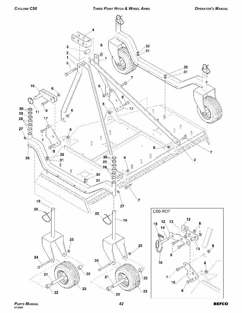
CYCLONE C50 THREE POINT HITCH & WHEEL ARMS OPERATOR’S MANUAL
PARTS MANUAL 42 BEFCO07/2009

2Wheel arm C50-RD7; Ver. H & above040-69412Wheel arm C50-RD7; Ver. G & below040-69322Wheel arm C50-RD6; Ver. H & above030-69412Wheel arm C50-RD6; Ver. G & below030-69322Wheel arm C50-RD5; Ver. H & above020-69412Wheel arm C50-RD5; Ver. G & below020-69392Wheel arm C50-RD4; Ver. H & above010-69412Wheel arm C50-RD4; Ver. G & below010-6939264Nut M14003-0358254Bolt TE M14x150000-6619248Dust cover, air tire; Ver. N (#272148) & above (not shown)000-69628Bearing, air tire; Ver. N (#272148) & above (not shown)005-01424Air tire 11”; Ver. N (#272148) & above000-69648Bearing, air tire; Ver. M (#272147) & below (not shown)000-69688Steel retainer, air tire; Ver. M (#272147) & below (not shown)000-6969A4Air tire 11”; Ver. M (#272147) & below 19000-69678Bearing, hard tire (not shown)503-723B4Hard tire000-6923Y238Air tire outer spacer 11”; Ver. N (#272148) & above000-69728Hard tire outer wheel spacer000-6585224Inner spacer000-6584214Cotter pin since 07/99000-87834Cotter pin Ø6x46000-6610204Wheel yoke000-6946192Linking plate C50-RD7 only000-6854182Linking plate C50-RD4, RD5 & RD6000-6540172Chain000-8506162Cotter pin C50-RD7003-2366152Pin C50-RD7003-8346144Spacer C50-RD7000-6827134Lower hitch arm C50-RD7 only000-6826122Lynch pin001-8266112Hitch block000-657310-Bolt TE M16x55003-321894Bolt TE M16x50000-236584Bolt TE M16x45000-65787-Nut M16000-558161Bolt TE M16x140000-689151Upper plate000-682841Spacer since 01/97000-68291Spacer008-505732Top hitch arm C50-RD7000-68212Top hitch arm C50-RD6030-65702Top hitch arm C50-RD5020-65702Top hitch arm C50-RD4010-657022Top hitch support C50-RD7000-68232Top hitch support000-68221Qty.DescriptionPart #Ref.
CYCLONE C50 THREE POINT HITCH & WHEEL ARMS OPERATOR’S MANUAL
PARTS MANUAL 43 BEFCO07/2009
19 Wheel no longer available, part # 000-6964 should be ordered instead. Serial # 272147 and below must also ordertwo (2) outer wheel spacers (000-6972) when replacing wheel.

CYCLONE C50 THREE POINT HITCH & WHEEL ARMS OPERATOR’S MANUAL
PARTS MANUAL 44 BEFCO07/2009

16Nut M10003-0156 3216Flat washer Ø10003-0157318Spacer ¼”000-6589304Spacer ½”000-65872912Spacer 1”000-6586284Grease fitting000-106527Qty.DescriptionPart #Ref.
CYCLONE C50 THREE POINT HITCH & WHEEL ARMS OPERATOR’S MANUAL
PARTS MANUAL 45 BEFCO07/2009

CYCLONE C50 TRANSMISSION & SPINDLE OPERATOR’S MANUAL
PARTS MANUAL 46 BEFCO06/2007

-Spindle assembly 000-6629C203Bearing 6205-Z000-6634A193Spacer000-6640183Spindle000-6648173Bearing 6205-ZZ000-6626A163Spacer washer 000-6606153Cover000-663614
3Key 8x7x25000-6639133Spindle shaft000-6649123Gator blade C50-RD7 (option)000-6690G3Gator blade C50-RD6 (option) 000-6845G3Gator blade C50-RD5 (option) 000-6641G3Flat blade C50-RD7 (option)000-6690F3Flat blade C50-RD6 (option) 000-6845F3Flat blade C50-RD5 (option) 000-6641F3Flat blade C50-RD4 (option) 000-6795F3High lift blade C50-RD7 (option) 000-6690B3High lift blade C50-RD6 (option) 000-6845B3High lift blade C50-RD5 (option) 000-6641B3High lift blade C50-RD4 (option) 000-6795B3Mulching blade C50-RD7 (option) 000-6690M3Mulching blade C50-RD6 (option) 000-6845M3Mulching blade C50-RD5 (option) 000-6641M3Mulching blade C50-RD4 (option) 000-6795M3Standard blade C50-RD7000-66903Standard blade C50-RD6000-68453Standard blade C50-RD5000-66413Standard blade C50-RD4000-6795113Disc spring 000-8560103Blade bolt000-6659912Bolt TE M10x30000-1278812Nut M10003-015673Grease fitting 002-903663Nut M25000-669852Belt 5VX1000 C50-RD7000-66942Belt 5VX850 C50-RD6000-68482Belt 5VX710 C50-RD5000-66932Belt 5VX630 C50-RD4000-679841Pulley SPB 250x2000-669231Pulley SPB 190x2 C50-RD7000-68611Pulley SPB 160x2 C50-RD6000-68411Pulley SPB 130x2 C50-RD5000-6621 1Pulley SPB 120x2 C50-RD4000-679122Pulley SPB 190x1 C50-RD7000-68622Pulley SPB 160x1 C50-RD6000-68422Pulley SPB 130x1 C50-RD5000-66222Pulley SPB 120x1 C50-RD4000-67921Qty.DescriptionPart #Ref.
CYCLONE C50 TRANSMISSION & SPINDLE OPERATOR’S MANUAL
PARTS MANUAL 47 BEFCO06/2007

CYCLONE C50 ACCESSORIES (OPTION) OPERATOR’S MANUAL
PARTS MANUAL 48 BEFCO06/2007
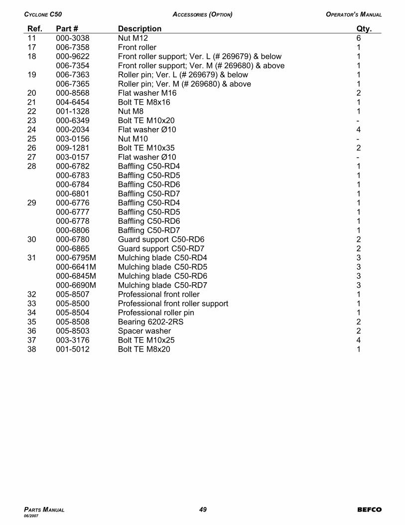
1Bolt TE M8x20001-5012384Bolt TE M10x25003-3176372Spacer washer 005-8503362Bearing 6202-2RS005-8508351Professional roller pin005-8504341Professional front roller support 005-8500331Professional front roller005-8507323Mulching blade C50-RD7 000-6690M3Mulching blade C50-RD6 000-6845M3Mulching blade C50-RD5 000-6641M3Mulching blade C50-RD4000-6795M312Guard support C50-RD7000-68652Guard support C50-RD6000-6780301Baffling C50-RD7000-68061Baffling C50-RD6000-67781Baffling C50-RD5000-67771Baffling C50-RD4000-6776291Baffling C50-RD7000-68011Baffling C50-RD6000-67841Baffling C50-RD5000-67831Baffling C50-RD4000-678228-Flat washer Ø10003-0157272Bolt TE M10x35009-128126-Nut M10003-0156254Flat washer Ø10000-203424-Bolt TE M10x20000-6349231Nut M8001-1328221Bolt TE M8x16004-6454212Flat washer M16000-8568201Roller pin; Ver. M (# 269680) & above006-73651Roller pin; Ver. L (# 269679) & below006-7363191Front roller support; Ver. M (# 269680) & above006-73541Front roller support; Ver. L (# 269679) & below000-9622181Front roller 006-7358176Nut M12000-303811Qty.DescriptionPart #Ref.
CYCLONE C50 ACCESSORIES (OPTION) OPERATOR’S MANUAL
PARTS MANUAL 49 BEFCO06/2007

CYCLONE C50 QUICK HITCH ADAPTER (OPTION) OPERATOR’S MANUAL
PARTS MANUAL 50 BEFCO08/2008

1C50 & C70 Quick Hitch Adapter assembly manual971-214B-Quick Hitch Adapter, complete002-8001Bolt TE M16x14024000-6891124Nut M1623000-5581114Bolt TE M16x5022000-2365102Linking plate C50-RD7 only21000-68542Linking plate 20000-654092Stover nut M20000-550784Stover nut M16000-558171Bolt M16x110007-034662Bolt M16x65000-988452Bolt M20x160503-300B42Floating yoke503-815B31Floating top link503-817B21A-frame support503-816B1Qty.DescriptionPart #Ref.
CYCLONE C50 QUICK HITCH ADAPTER (OPTION) OPERATOR’S MANUAL
PARTS MANUAL 51 BEFCO08/2008
24 This bolt (000-6891) comes with the mower and is not part of the Quick Hitch Adapter kit.
23 The four (4) bolts (000-2365) and (4) nuts (000-5581) come with the mower and are not part of the Quick HitchAdapter kit.
22 The four (4) bolts (000-2365) and (4) nuts (000-5581) come with the mower and are not part of the Quick HitchAdapter kit.
21 The linking plates come with the mower and are not part of the Quick Hitch Adapter kit.
20 The linking plates come with the mower and are not part of the Quick Hitch Adapter kit.
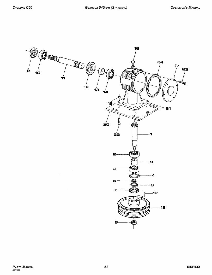
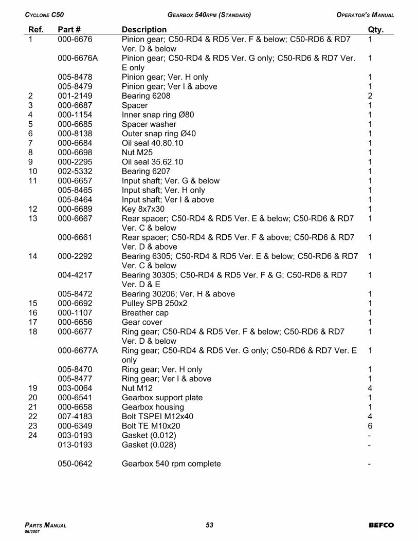
CYCLONE C50 GEARBOX 540RPM (STANDARD) OPERATOR’S MANUAL
PARTS MANUAL 52 BEFCO06/2007
-Gearbox 540 rpm complete050-0642
-Gasket (0.028)013-0193 - Gasket (0.012)003-0193246Bolt TE M10x20000-6349234Bolt TSPEI M12x40007-4183221Gearbox housing000-6658 211Gearbox support plate000-6541204Nut M12003-0064191Ring gear; Ver I & above005-84771Ring gear; Ver. H only005-8470
1Ring gear; C50-RD4 & RD5 Ver. G only; C50-RD6 & RD7 Ver. Eonly
000-6677A
1Ring gear; C50-RD4 & RD5 Ver. F & below; C50-RD6 & RD7Ver. D & below
000-6677181Gear cover000-6656171Breather cap000-1107161Pulley SPB 250x2000-6692151Bearing 30206; Ver. H & above005-8472
1Bearing 30305; C50-RD4 & RD5 Ver. F & G; C50-RD6 & RD7Ver. D & E
004-4217
1Bearing 6305; C50-RD4 & RD5 Ver. E & below; C50-RD6 & RD7Ver. C & below
000-229214
1Rear spacer; C50-RD4 & RD5 Ver. F & above; C50-RD6 & RD7Ver. D & above
000-6661
1Rear spacer; C50-RD4 & RD5 Ver. E & below; C50-RD6 & RD7Ver. C & below
000-6667131Key 8x7x30000-6689121Input shaft; Ver I & above005-84641Input shaft; Ver. H only005-84651Input shaft; Ver. G & below000-6657111Bearing 6207002-5332101Oil seal 35.62.10000-229591Nut M25000-669881Oil seal 40.80.10000-668471Outer snap ring Ø40 000-813861Spacer washer 000-668551Inner snap ring Ø80 000-115441Spacer000-668732Bearing 6208001-214921Pinion gear; Ver I & above005-84791Pinion gear; Ver. H only005-8478
1Pinion gear; C50-RD4 & RD5 Ver. G only; C50-RD6 & RD7 Ver.E only
000-6676A
1Pinion gear; C50-RD4 & RD5 Ver. F & below; C50-RD6 & RD7Ver. D & below
000-66761Qty.DescriptionPart #Ref.
CYCLONE C50 GEARBOX 540RPM (STANDARD) OPERATOR’S MANUAL
PARTS MANUAL 53 BEFCO06/2007

CYCLONE C50 GEARBOX 1000RPM (OPTION) OPERATOR’S MANUAL
PARTS MANUAL 54 BEFCO06/2007

-Gearbox 1000 rpm complete; since 01/98050-0572-Gearbox 1000 rpm complete; until 01/98 26050-0624
1Bearing 30305004-4217271Breather cap000-1107261Ring gear000-691125-Gasket (0.028)013-0193 - Gasket (0.012)003-0193246Bolt TE M10x20000-6349234Bolt TSPEI M12x40007-4183221Gearbox housing000-6658 211Gearbox support plate000-6541204Nut M12003-0064192Outer snap ring Ø35004-2122181Gear cover000-6656171Pulley SPB 250x2 540 & 1000 rpm; since 01/98000-66921Pulley SPB 140x2 1000 rpm; until 01/98 25000-6770151Spacer washer 004-4223141Input shaft000-5556131Key 8x7x30000-6689121Spacer 000-6853111Bearing 6207002-5332101Oil seal 35.62.10000-229591Nut M25000-669881Oil seal 40.80.10000-668471Outer snap ring Ø40 000-813861Spacer washer 000-668551Inner snap ring Ø80 000-115441Spacer000-668732Bearing 6208001-214921Pinion Gear000-69121Qty.DescriptionPart #Ref.
CYCLONE C50 GEARBOX 1000RPM (OPTION) OPERATOR’S MANUAL
PARTS MANUAL 55 BEFCO06/2007
26 Gearbox 050-0624 no longer available. Gearbox 050-0572 should be used instead. Pulley and belts need to bereplaced also (see footnote above).
25 Pulley 000-6770 no longer available, when used the following belts were mounted on 1000 rpm mower:000-6697 Belt C50-RD4 1000 rpm only until 01/98 Qty. 2000-6769 Belt C50-RD5 1000 rpm only until 01/98 Qty. 2000-6843 Belt C50-RD6 1000 rpm only until 01/98 Qty. 2Pulley 000-6692 can be used instead with the following belts:000-6798 Belt 5VX630 C50-RD4 (540 &1000 rpm) Qty. 2000-6693 Belt 5VX710 C50-RD5 (540 &1000 rpm) Qty. 2000-6848 Belt 5VX850 C50-RD6 (540 &1000 rpm) Qty. 2000-6694 Belt 5VX1000 C50-RD7 (540 &1000 rpm) Qty. 2

CYCLONE C50 DRIVELINE OPERATOR’S MANUAL
SERIAL #277830 & BELOW
PARTS MANUAL 56 BEFCO05/2009

-Driveline complete C50-RD6, RD7050-0415-Driveline complete C50-RD5050-0414-Driveline complete C50-RD4050-0413
1Decal “DANGER - Guard missing, do not operate” outer tube950-464B181Decal “DANGER - Rotating driveline, keep away” outer shield950-463B171Complete shielding C50-RD6, RD72990SL4068C1Complete shielding C50-RD52890SL4053C1Complete shielding C50-RD42790SL4040C161Inner locking ring; #277830 & below1784211C151Inner tube rigid cone; #277830 & below1784202C142Stiffening ring; #277830 & below1213233C131Long cone (implement end); #277830 & below1784205C121Male tube shield C50-RD6, RD71872068C1Male tube shield C50-RD51872053C1Male tube shield C50-RD41872040C111Female tube shield C50-RD6, RD71773068C1Female tube shield C50-RD51773053C1Female tube shield C50-RD41773040C102Chain1006065C92Pin; #277830 & below1784212C81Standard cone (tractor end); #277830 & below1784203C71Outer tube rigid cone; #277830 & below1784201C61Outer locking ring; #277830 & below1784210C51Inner tube C50-RD6, RD71953072NC1Inner tube C50-RD51953057NC1Inner tube C50-RD41953044NC41Outer tube C50-RD6, RD71943070NC1Outer tube C50-RD51943055NC1Outer tube C50-RD41943042NC32Cross and bearing1003020C22PTO yoke1023010C1Qty.DescriptionPart #Ref.
CYCLONE C50 DRIVELINE OPERATOR’S MANUAL
SERIAL #277830 & BELOW
PARTS MANUAL 57 BEFCO05/2009
29 Complete shielding is interchangeable with part #96SL4068C.
28 Complete shielding is interchangeable with part #96SL4053C.
27 Complete shielding is interchangeable with part #96SL4040C.
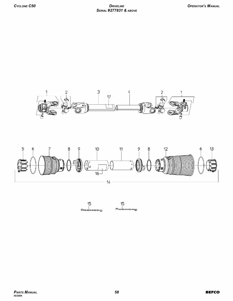
CYCLONE C50 DRIVELINE OPERATOR’S MANUAL
SERIAL #277831 & ABOVE
PARTS MANUAL 58 BEFCO05/2009
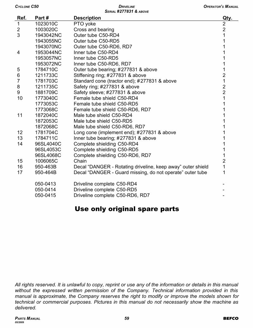
-Driveline complete C50-RD6, RD7050-0415-Driveline complete C50-RD5050-0414-Driveline complete C50-RD4050-0413
1Decal “DANGER - Guard missing, do not operate” outer tube950-464B171Decal “DANGER - Rotating driveline, keep away” outer shield950-463B162Chain1006065C151Complete shielding C50-RD6, RD796SL4068C1Complete shielding C50-RD596SL4053C1Complete shielding C50-RD496SL4040C141Inner tube bearing; #277831 & above1784711C131Long cone (implement end); #277831 & above1781704C121Male tube shield C50-RD6, RD71872068C1Male tube shield C50-RD51872053C1Male tube shield C50-RD41872040C111Female tube shield C50-RD6, RD71773068C1Female tube shield C50-RD51773053C1Female tube shield C50-RD41773040C102Safety sleeve; #277831 & above1881709C92Safety ring; #277831 & above1211735C81Standard cone (tractor end); #277831 & above1781703C72Stiffening ring; #277831 & above1211733C61Outer tube bearing; #277831 & above1784710C51Inner tube C50-RD6, RD71953072NC1Inner tube C50-RD51953057NC1Inner tube C50-RD41953044NC41Outer tube C50-RD6, RD71943070NC1Outer tube C50-RD51943055NC1Outer tube C50-RD41943042NC32Cross and bearing1003020C22PTO yoke1023010C1Qty.DescriptionPart #Ref.
Use only original spare parts
All rights reserved. It is unlawful to copy, reprint or use any of the information or details in this manualwithout the expressed written permission of the Company. Technical information provided in thismanual is approximate, the Company reserves the right to modify or improve the models shown fortechnical or commercial purposes. Pictures in this manual do not necessarily show the machine asdelivered.
CYCLONE C50 DRIVELINE OPERATOR’S MANUAL
SERIAL #277831 & ABOVE
PARTS MANUAL 59 BEFCO05/2009

BE
FC
O C
50
-RD
4,
RD
5,
RD
6,
RD
7 (
US
) P
rin
ted
in
th
e U
SA
, Ju
ly 1
6,
20
09
P.O. Box 6036
Rocky Mount, NC 27802-6036
Tel.: 252.977.9920 - Fax: 252.977.9718
www.befco.com
®
®