Beers + Hoffman
94
Page 1 of 8 55 N. Water Street, Lititz, PA 17543 (717) 625-0400 (717) 625-0402 FAX 815 Cumberland Street, Lebanon, PA 17042 (717) 273-7774 * 1104 Bridge Street, New Cumberland, PA 17070 (717) 774-7450 www.beersltd.com Beers + Hoffman Scott L. Shonk, AIA, LEED AP Peter D. Kerekgyarto, AIA, LEED AP Timothy M. Schwear, Assoc. AIA C. Bruce Christman, Jr, AIA, LEED AP, GAC Robert P. Hoffman, AIA South Londonderry Township Project #: 16-019 20 West Market St Campbelltown, PA 17010 Addendum No. 02 06 September 2016 The deadline for bids has been extended to Monday September 12, 2016 at 11:00 AM. Notice This Addendum is issued pursuant to the Conditions of the Contract dated March 14, 2016 for the Architectural, Interior Design, Structural and MEP Contract Documents. This Addendum serves to clarify, revise, and supersede information in the Project Manual (specifications), Drawings, and previously issued Addenda. Portions of the Addendum affecting the Contract Documents will be incorporated into the Contract by enumeration of the Addenda in the Owner/Contractor Agreement. Attachments 221116R - Domestic Water Piping 221316 – Dry-Pipe Sprinkler Systems 230713R - Duct Insulation 230719 - HVAC Piping Insulation- 232300 - Refrigerant Piping 233113R - Metal Ducts F101- Floor Plan, Notes, and Details MEP RFIs RFI Responses Question 01: Spec Section 093013-2.3-A-1 calls for 5/8 inch backer board, 3.9-B-1 calls for tile to be installed on GWB, General Notes 13 on A001 says backer board for all tile locations, Spec 092900 calls for ½ inch backer. Please clarify what is required. Answer: Modify 2.3-E-2, replace “½ inch” with “5/8 inch” Modify 3.9-B-1-a, replace “gypsum board” with “cementitious backer units” Question 02: E201: DWH-1 in Mechanical room 133 says it's fed with circuit A-33 but circuit 33 on A's panel schedule says "Receptacle Roof". DWH-1 is not shown on the panel schedule for panel A. Please clarify. Answer: On E201, Revise “A-33” for DWH-1 in room 133 to “A-41”. Revise “Spare” in circuit A- 41 in panel A schedule shown on E701 to “DWH-1. Question 03: 262913.03: Other than the manual motor switches for DS-1, DS-2 and DWH-1 are there any other manual or magnetic motor controllers furnished under the EC scope of work?
Transcript of Beers + Hoffman
Page 1 of 8 55 N. Water Street, Lititz, PA 17543 (717) 625-0400 (717) 625-0402 FAX
815 Cumberland Street, Lebanon, PA 17042 (717) 273-7774 * 1104 Bridge Street, New Cumberland, PA 17070 (717) 774-7450
www.beersltd.com
Beers + Hoffman
Scott L. Shonk, AIA, LEED AP
Peter D. Kerekgyarto, AIA, LEED AP
Timothy M. Schwear, Assoc. AIA
C. Bruce Christman, Jr, AIA, LEED AP, GAC
Robert P. Hoffman, AIA
South Londonderry Township Project #: 16-019
20 West Market St
Campbelltown, PA 17010
Addendum No. 02
06 September 2016
The deadline for bids has been extended to Monday September 12, 2016 at 11:00 AM.
Notice
This Addendum is issued pursuant to the Conditions of the Contract dated March 14, 2016 for the
Architectural, Interior Design, Structural and MEP Contract Documents. This Addendum serves to clarify,
revise, and supersede information in the Project Manual (specifications), Drawings, and previously issued
Addenda. Portions of the Addendum affecting the Contract Documents will be incorporated into the
Contract by enumeration of the Addenda in the Owner/Contractor Agreement.
Attachments
221116R - Domestic Water Piping
221316 – Dry-Pipe Sprinkler Systems
230713R - Duct Insulation
230719 - HVAC Piping Insulation-
232300 - Refrigerant Piping
233113R - Metal Ducts
F101- Floor Plan, Notes, and Details
MEP RFIs
RFI Responses
Question 01: Spec Section 093013-2.3-A-1 calls for 5/8 inch backer board, 3.9-B-1 calls for tile to be installed
on GWB, General Notes 13 on A001 says backer board for all tile locations, Spec 092900 calls for ½ inch
backer. Please clarify what is required.
Answer: Modify 2.3-E-2, replace “½ inch” with “5/8 inch”
Modify 3.9-B-1-a, replace “gypsum board” with “cementitious backer units”
Question 02: E201: DWH-1 in Mechanical room 133 says it's fed with circuit A-33 but circuit 33 on A's panel
schedule says "Receptacle Roof". DWH-1 is not shown on the panel schedule for panel A. Please clarify.
Answer: On E201, Revise “A-33” for DWH-1 in room 133 to “A-41”. Revise “Spare” in circuit A-
41 in panel A schedule shown on E701 to “DWH-1.
Question 03: 262913.03: Other than the manual motor switches for DS-1, DS-2 and DWH-1 are there any
other manual or magnetic motor controllers furnished under the EC scope of work?
Addenda No. 02
06 September 2016
Page 2 of 8
55 N. Water Street, Lititz, PA 17543 (717) 625-0400 (717) 625-0402 FAX
815 Cumberland Street, Lebanon, PA 17042 (717) 273-7774
www.beersltd.com
Answer: No.
Question 04: In specification section 233113 2.4.E.9 states to add perforated duct to the liner. These will
double the cost of any duct that is lined. Please verify that this is not required.
Answer: Metal ducts specification section 233113 revised and reissued to clarify materials
and application of duct wrap and duct liner.
Question 05: In specification section 231123 3.11.A refers to Exterior Painting section 099113. There is no
specification section 099113. Please provide this specification section.
Answer: Facility Natural-Gas Piping specification section 231123 under par. 3.11 delete par.
A. Follow painting guidelines of par. 3.11 B, C and D.
Question 06: Spec 221116-19, 3.12 G. & H. has galvanized-steel and SCH 40 PVC as acceptable piping
materials for the domestic water system. Is the acceptable per code?
Answer: Domestic water piping specification section 221116 revise and reissue to deleted
Galvanized and PVC references and additional clarifications to material and applications.
Question 07: If PEX is used for the domestic water; is it to be insulated?
Answer: Added par. 4 to specification section 220719 3.14 B. Items Not Insulated, 4. PEX Tube
branch piping.
Question 08: Detail-1 on drawing F101 indicates the incoming water line to be “cast iron”. Is this correct? The
spec calls for “ductile iron”.
Answer: Delete cast iron reference and follow the specification section 211100 Facility Fire-
Suppression Water-Service Piping.
Question 09: In specification section 233300 2.13.A refers to security bars for duct. I did not see any
indicated on the drawings. Please have the location of all security bars identified.
Answer: No security bars in the ductwork at this time.
Question 10: Please provide a specification for the refrigerant pipe and condensate pipe.
Answer: Added specification section 232300 Refrigerant Piping.
Drawing M101 and M103 add to Note #1 the following: Condensate drain piping shall be
Type M or Type DWV copper tubing
Question 11: GCO is blank on the plumbing schedule. Please provide basis of design.
Answer: GCO shall be the same as CO on P701 schedule. GCO shall be mounted at finished
grade with a 16” square x 6” deep concrete pad trowel smooth and edge.
Question 12: Are there any FD-2 on this project? It is in the schedule. We didn’t see any on the drawings.
Answer: Change FD-1 in Mechanical Room 133 to FD-2.
Change FD-1 in Garage (1 Bay) 145 to FD-2 with 4”x9” oval cast iron funnel.
Question 13: Spec 22131913-2, 2.2 A & B. Do not have the name FD-__ filled in. Also is “B.” used in this
section? (stainless steel) FD-__Garbage
Answer: Revise Sanitary Drains specification section 221319.13 par. 2.2 as follows:
2.2 A. Retain par. 1. Manufacturers:
2.2 A. Delete “(FD-_)”
Addenda No. 02
06 September 2016
Page 3 of 8
55 N. Water Street, Lititz, PA 17543 (717) 625-0400 (717) 625-0402 FAX
815 Cumberland Street, Lebanon, PA 17042 (717) 273-7774
www.beersltd.com
2.2 A. Delete par. 3 to 20.
2.2 B. Delete in its entirety.
Question 14: Note 2 on drawing P501 calls for an audible alarm device for leak detection on the water
heater. No spec. Please confirm that this by the ATC contractor.
Answer: On drawing P501, Gas Fired Water Heater Detail, delete note #2.
Question 15: According to framing plans there is an unconditioned attic space. FP Plan F101 calls for a wet
system and does not indicate to protect this space.
Answer: Reviewing notes, meeting minutes and code.
Question 16: Water supply will be a Combo fire / domestic line with backflow preventer in the pit. Plan F101
detail # 2 shows the water line entrance into the building. An additional fire protection backflow preventer
is not shown on this detail, and as such the fire line water could contaminate the domestic supply inside the
building. An additional backflow preventer should be provided for the fire line inside the building.
Answer: Revise detail #2 on F101 to include a Backflow Preventer - Double Check Valve
Detector Assembly.
Add specification note to detail #2 for a Watts (or equal) Series 757DCDA BFG GPM : 6 Watts
757DCDA BFG GPM: 6 Double Check Valve Detector Assembly - two removable and
serviceable independent tri-link check modules within a single housing, 304 schedule 40
stainless steel housing and sleeve with groove end connections, reversible elastomeric discs,
sleeved access port, two drip tight shut-off valves UL/FM grooved gear operated butterfly
valves with tamper switch, 6"Ø (152 mm) pipe connection, four test cocks, gallons per minute
reading, auxiliary bypass-line consisting of double check backflow assembly with test cocks
and water meter. Used primarily on fire line sprinkler systems when it is necessary to monitor
unauthorized use of water.
Question 17: Is the township paying for any fees from Met-Ed for both the permanent electrical service and
the temporary electrical service? Per the discussion at the prebid meeting, it is my understanding that the
GC will pay for the temporary electric usage cost. Please confirm.
Answer: The township will cover Met-Ed fees. The GC will be responsible for all usage.
Question 18: Per the discussion at the prebid meeting, it is my understanding that the township will pay for
all permits, but the EC is responsible for a 3rd party electrical inspection by Commonwealth Code
Inspection Service. Please confirm.
Answer: Correct
Question 19: Do we need to install disconnects for the garage door openers and who is responsible to
supply them.
Answer: Disconnects come as integral component of operator.
Question 20: Is the GC installing all of the Monitor’s shown to be supplied by the owner? Is the owner
providing the mounting hardware?
Answer: Yes, hardware by owner and installed by GC.
Question 21: Is all downspout piping being taken care of by the Township or the GC?
Answer: Sub-grade piping and boot receivers will be installed by owner.
Addenda No. 02
06 September 2016
Page 4 of 8
55 N. Water Street, Lititz, PA 17543 (717) 625-0400 (717) 625-0402 FAX
815 Cumberland Street, Lebanon, PA 17042 (717) 273-7774
www.beersltd.com
Question 22: Are the water line and meter pit by the GC or the Plumbing Contractor (plans reference
both)?
Answer: General Contractor responsible for everything 5’ or more from the building.
Plumbing Contractor is responsible for remainder.
Question 23: Is the lighting by the GC or the Electrical Contractor (plans reference both)?
Answer: Electrical Contractor
Question 24: Who is responsible for the lawn seeding?
Answer: General Contractor
Question 25: Who is responsible for the landscaping, trees, etc.?
Answer: General Contractor
Question 26: Who is responsible to supply the downspout boots and the connection to the owner supplied
roof PVC roof drain lines?
Answer: These will be provided and installed by the owner.
Question 27: Which prime contractor is responsible for the generator pad and bollards at the generator
pad?
Answer: General Contractor
Question 28: Which prime contractor is responsible for the light pole foundations?
Answer: General Contractor
Question 29: Who is to supply and install the interior signage?
Answer: General Contractor
Question 30: Is there an apron under the PLAM window stools?
Answer: Yes, 3” tall.
Question 31: A101 Lobby 101 states new display case by owner; 1/A401 states New Display Case by G.C. Please
clarify who is to provide and install?
Answer: The display case will be by owner. Please disregard reference to case by G.C.
Question 32: Do all windows get PLAM sills? Do they get PLAM aprons? Are they all GWB returns?
Answer: Yes, all windows received PLAM sills with a 3” apron and GWB jamb and head
returns.
Question 33: Please clarify who is responsible for temp heat. Section 011200-5 states the GC is with no cutoff
point. Then in 011200-7 it states by MC after permanent enclosure. At the pre-bid it was stated this was by
the GC. Please clarify.
Answer: 011200-1.6D refers to General Contract responsible for temporary heating. This is
prior to permanent enclosure. It should be noted that per 011200-1.6E2a General Contractor
is responsible for usage charges until Substantial Completion. 011200-1.9B2 refers to
Mechanical Contract responsible for temporary heating after permanent enclosure.
Addenda No. 02
06 September 2016
Page 5 of 8
55 N. Water Street, Lititz, PA 17543 (717) 625-0400 (717) 625-0402 FAX
815 Cumberland Street, Lebanon, PA 17042 (717) 273-7774
www.beersltd.com
Question 34: Is the fence 6’ or 8’? There are references to both. What material is to be used.
Answer: 8’
Question 35: Is the insulation batt fiberglass or fireproof?
Answer: Fiberglass
Question 36: Section 0122003.1.D: The description of the Unit Prices says to include (1) unit in the base bid.
Are the unit prices treated as an additional allowance or are they stand alone numbers that are only listed
on the bid form?
Answer: The unit price, by itself, is not an additional allowance; it is a standalone value that
the related quantity allowance is based on.
Question 37: According to framing plans there is an unconditioned attic space. FP Plan F101 calls for a wet
system and does not indicate to protect this space.
Answer: E201: Add a motor rated switch to the west wall of Garage 145 for dry-pipe
sprinkler’s air compressor. Switch shall be rated for 20A, single-phase, 120V in NEMA 1
enclosure. Connect compressor to switch and home run to circuit A-43 with (2)#12, #12G in
3/4" conduit. Revise A-43 in panel A schedule from “Spare” to “Dry-pipe Sprinkler”.
Revised F101 to include dry valve system. Added specification section 211316 Dry-Pipe
Sprinkler Systems.
Question 38: Section 004116: The bid form asks for a lump sum base bid and then says Bid allowances "for
inclusion in each Base Bid". Spec section 012100 3.3.D says the base bid shall include the allowances.
Should the allowances be in our base bid or will they be listed separate on the bid form and then be added
to the base bid?
Answer: Allowances shall be included in/added to the Prime Contractor’s total base bid
amount that the contractor writes in on page 2 of the Bid Form; on page 3 of the Bid Form,
allowance amounts are itemized (the amount of each allowance is based the requisite # of
units of measurement based on an assigned unit price, which is itemized on the last page of
the Bid Form.
Question 39: Section 011200: 1.10.B.1 EC is to provide temp elect to field offices. Has the laydown area for
trailers been identified?
Answer: To be coordinated by contractors during construction.
Question 40: Section 017000: 3.2.A There is a MetEd fee to extend the electrical primary line. Are we
supposed to include that in our bid or will that be covered directly by the owner?
Answer: This fee will be covered by the owner.
Question 41: Section 011200: 1.6C-Are dumpsters by each prime or does GC have them all?
Answer: GC is responsible for all dumpsters.
Question 42: Section 092900: 3.7 d 2 – is level 5 finishing required at all exposed gyp?
Answer: References to Level 5 wall finishes are to be omitted. Surfaces are to receive Level 4
finish throughout
Question 43: Section 061600: Calls for fire treated sheathing for all walls, but not roofs (only where shown on
plans) , is this correct?
Answer: Fire treated wood sheathing is only required where indicated on the drawings.

Addenda No. 02
06 September 2016
Page 6 of 8
55 N. Water Street, Lititz, PA 17543 (717) 625-0400 (717) 625-0402 FAX
815 Cumberland Street, Lebanon, PA 17042 (717) 273-7774
www.beersltd.com
Question 44: Section 061053: 2.3 F calls for just about everything to be fire treated- is this correct? It lists roof
framing, since there is no truss spec, do you want fire treated trusses?
Answer: Fire treated wood framing is not required. References are to be omitted.
Question 45: Section 102800: Is the GC providing the showers? Is the GC providing the warm air hand
dryers?
Answer: Yes, the GC is providing the showers and the warm air hand dryers.
Question 46: For the site package- sheet 1 of 12: It looks like the notes were drawn as if this was single prime-
please clarify
Answer: Where indicated in the site package, reference to “GC” is to be interpreted as the
appropriate prime contractor.
Question 47: Line 5- Who is doing water line/water meter pit work?
Answer: The general contractor is responsible for all work outside of 5’ from the building.
Question 48: Line 12- Is all work related to site electric/lighting including trenching by EC?
Answer: Yes
Question 49: Township is doing striping of parking lot- do they have parking stops and signage since it is
usually the same sub?
Answer: Yes, this will be completed by the Township.
Question 50: Township is doing pavement removal and restoration in Market St- Do they have traffic
control?
Answer: Yes
Question 51: Are E&S controls handled by the township since they are doing the bulk of the site work?
Answer: Yes
Question 52: Cover sheet 1 of 12: Site Work Coordination Note #5: Please clarify what contract the exterior
water line work is to be completed by.
Answer: As indicated on sheet P001, the General Contractor is responsible for all work 5’ or
more from the building. Everything within is the responsibility of the Plumbing Contractor.
Question 53: Cover sheet 1 of 12: Site Work Coordination Note #6: Please clarify that all underground utility
work within the building pad is to be completed by each prime contractor.
Answer: Correct.
Question 54: Cover sheet 1 of 12: Site Work Coordination Note #12: Please clarify that all site lighting,
trenching and wiring is by the electrical prime contract
Answer: Correct.
Question 55: Cover sheet 1 of 12: I don’t see anywhere that it requires a Consent of Surety at project
completion. Can you verify if that is correct?
Addenda No. 02
06 September 2016
Page 7 of 8
55 N. Water Street, Lititz, PA 17543 (717) 625-0400 (717) 625-0402 FAX
815 Cumberland Street, Lebanon, PA 17042 (717) 273-7774
www.beersltd.com
Answer: The required Consent of Surety can be found in General Conditions Section
9.10.2(iv).
Question 56: Will new Met-Ed service be needed during construction or only at the time of building
completion?
Answer: Transfer to new electrical service will need to occur during construction.
Question 57: Will the GC be responsible for any conduit or coordinate for tele-com services?
Answer: No, all tele-com will be coordinated by the owner
Question 58: Who is responsible for staking out building corner locations?
Answer: The General Contractor
Specification Changes
042613 – MASONRY VENEER (modifications)
o 2.8.2.1: Delete this item
o 2.8.2.2: Delete this item
o 2.8.2.3: Replace “85 cell vent” with “QV-Quadro-Vent”
o 3.8.4.2: Replace “use wicking…as possible” with “space weep holes 24 inches on center
unless otherwise indicated.”
o 3.8.4.3: Delete this item
o 3.8.4.4: Delete this item
o 3.8.4.5: Delete this item
061600 – SHEATHING
o Part 2 (modify)
Add paragraph 2.6 as follows:
A. Preservative Treatment by Pressure Process: AWPA U1: Use Category UC@ for
interior construction not in contact with ground, use Category UC3b for exterior
construction not in contact with ground, and use Category UC4a for items in contact
with ground.
B. Mark plywood with appropriate classification marking of an inspection agency
acceptable to authorities having jurisdiction.
C. Application: Treat items indicated on Drawings and plywood in contact with
masonry or concrete or used with roofing, flashing, vapor barriers, and waterproofing.
071326 – SELF ADHERING SHEET WATERPROOFING
o 1.2.A (modifications)
1.2.A.1: Delete this item
1.2.A.3: Delete this item
1.2.A.4: Delete this item
1.2.A.5: Delete this item
o 2.3.2: Delete this item
o 3.2.G.1.b: Delete this item
o 3.5.A: Delete this item
089119 – FIXED LOUVERS
Addenda No. 02
06 September 2016
Page 8 of 8
55 N. Water Street, Lititz, PA 17543 (717) 625-0400 (717) 625-0402 FAX
815 Cumberland Street, Lebanon, PA 17042 (717) 273-7774
www.beersltd.com
o 2.3.A: Replace “Horizontal Drainable Blue Louver” with “Horizontal Wind-Driven-Rain-Resistant
Louver”
o 2.3.A.1: Replace “Model DVC 5704 Storm Resistant Louver” with “Model RS-5300 Wind-Driven-
Rain-Resistant-Louver”
o 2.3.A.2: Replace “4 inches (100 mm)” with “5 inches (127 mm)”
o 7.3.A.2: Replace “0.080 inch (2.03 mm)” with “0.060 inch (1.52 mm)”
o 2.3.A.5.a: Replace “8.0 sq ft (0.74 sq. m)” with “47%”
o 2.3.A.5:
2.3.A.5.b: Delete this item
2.3.A.5.c: Delete this item
2.3.A.6: Delete this item
End of Addenda No. 02
South Londonderry Township - New Municipal & Police Facility B + H 16-019
DRY-PIPE SPRINKLER SYSTEMS 211316 - 1
SECTION 211316 - DRY-PIPE SPRINKLER SYSTEMS
PART 1 - GENERAL
1.1 RELATED DOCUMENTS
A. Drawings and general provisions of the Contract, including General and Supplementary Conditions and Division 01 Specification Sections, apply to this Section.
1.2 SUMMARY
A. Section Includes:
1. Pipes, fittings, and specialties. 2. Specialty valves. 3. Sprinkler specialty pipe fittings. 4. Sprinklers. 5. Alarm devices. 6. Control panels. 7. Pressure gages.
B. Related Requirements:
1. Section 211119 "Fire Department Connections" for exposed-, flush-, and yard-type fire department connections.
2. Section 230523 "General-Duty Valves for Water-Based Fire-Suppression Piping" for ball, butterfly, check, gate, post-indicator, and trim and drain valves.
1.3 DEFINITIONS
A. Standard-Pressure Sprinkler Piping: Dry-pipe sprinkler system piping designed to operate at working pressure of 175-psig maximum.
1.4 ACTION SUBMITTALS
A. Product Data: For each type of product.
1. Include rated capacities, operating characteristics, electrical characteristics, and furnished specialties and accessories.
B. Shop Drawings: For dry-pipe sprinkler systems.
1. Include plans, elevations, sections, and attachment details. 2. Include diagrams for power, signal, and control wiring.
C. Delegated-Design Submittal: For dry-pipe sprinkler systems indicated to comply with performance requirements and design criteria, including analysis data signed and sealed by the qualified professional engineer responsible for their preparation.
South Londonderry Township - New Municipal & Police Facility B + H 16-019
DRY-PIPE SPRINKLER SYSTEMS 211316 - 2
1.5 INFORMATIONAL SUBMITTALS
A. Coordination Drawings: Sprinkler systems, drawn to scale, on which the following items are shown and coordinated with each other, using input from installers of the items involved:
1. Domestic water piping. 2. Compressed air piping. 3. HVAC ductwork. 4. Items penetrating finished ceiling including the following:
a. Lighting fixtures. b. Air outlets and inlets.
B. Qualification Data: For qualified Installer and professional engineer.
C. Approved Sprinkler Piping Drawings: Working plans, prepared according to NFPA 13, that have been approved by authorities having jurisdiction, including hydraulic calculations if applicable.
D. Fire-hydrant flow test report.
E. Field Test Reports and Certificates: Indicate and interpret test results for compliance with performance requirements and as described in NFPA 13. Include "Contractor's Material and Test Certificate for Aboveground Piping."
F. Field quality-control reports.
1.6 CLOSEOUT SUBMITTALS
A. Operation and Maintenance Data: For dry-pipe sprinkler systems and specialties to include in emergency, operation, and maintenance manuals.
1.7 MAINTENANCE MATERIAL SUBMITTALS
A. Furnish extra materials that match products installed and that are packaged with protective covering for storage and identified with labels describing contents.
1. Sprinkler Cabinets: Finished, wall-mounted, steel cabinet with hinged cover, and with space for minimum of six spare sprinklers plus sprinkler wrench. Include number of sprinklers required by NFPA 13 and sprinkler wrench. Include separate cabinet with sprinklers and wrench for each type of sprinkler used on Project.
1.8 QUALITY ASSURANCE
A. Installer Qualifications:
1. Installer's responsibilities include designing, fabricating, and installing sprinkler systems and providing professional engineering services needed to assume engineering responsibility. Base calculations on results of fire-hydrant flow test.
a. Engineering Responsibility: Preparation of working plans, calculations, and field test reports by a qualified professional engineer.
South Londonderry Township - New Municipal & Police Facility B + H 16-019
DRY-PIPE SPRINKLER SYSTEMS 211316 - 3
PART 2 - PRODUCTS
2.1 SYSTEM DESCRIPTIONS
A. Dry-Pipe Sprinkler System: Automatic sprinklers are attached to piping containing compressed air. Opening of sprinklers releases compressed air and permits water pressure to open dry-pipe valve. Water then flows into piping and discharges from opened sprinklers.
2.2 PERFORMANCE REQUIREMENTS
A. Sprinkler system equipment, specialties, accessories, installation, and testing shall comply with the following:
1. NFPA 13.
B. Standard-Pressure Piping System Component: Listed for 175-psig minimum working pressure.
C. Delegated Design: Engage a qualified professional engineer, as defined in Section 014000 "Quality Requirements," to design wet-pipe sprinkler systems.
1. Available fire-hydrant flow test records are shown on Drawing F101.
D. Sprinkler system design shall be approved by authorities having jurisdiction.
1. Margin of Safety for Available Water Flow and Pressure: 10 percent, including losses through water-service piping, valves, and backflow preventers.
2. Sprinkler Occupancy Hazard Classifications:
a. Automobile Parking Areas: Ordinary Hazard, Group 1. b. Building Service Areas: Ordinary Hazard, Group 1. c. Unused Attic: Light Hazard. d. Electrical Equipment Rooms: Ordinary Hazard, Group 1. e. General Storage Areas: Ordinary Hazard, Group 1. f. Mechanical Equipment Rooms: Ordinary Hazard, Group 1. g. Office and Public Areas: Light Hazard.
3. Minimum Density for Automatic-Sprinkler Piping Design:
a. Light-Hazard Occupancy: 0.10 gpm over 1500-sq. ft. area. b. Ordinary-Hazard, Group 1 Occupancy: 0.15 gpm over 1500-sq. ft. area.
4. Maximum Protection Area per Sprinkler: According to UL listing.
2.3 STEEL PIPE AND FITTINGS
A. Standard-Weight, Galvanized-Steel Pipe: ASTM A 53/A 53M, Type E or Grade B. Pipe ends may be factory or field formed to match joining method.
B. Schedule 30, Galvanized-Steel Pipe: ASTM A 135/A 135M; ASTM A 795/A 795M, Type E; or ASME B36.10M wrought steel, with wall thickness not less than Schedule 30 and not more than Schedule 40. Pipe ends may be factory or field formed to match joining method.
South Londonderry Township - New Municipal & Police Facility B + H 16-019
DRY-PIPE SPRINKLER SYSTEMS 211316 - 4
C. Thinwall Galvanized-Steel Pipe: ASTM A 135/A 135M or ASTM A 795/A 795M, threadable, with wall thickness less than Schedule 30 and equal to or greater than Schedule 10. Pipe ends may be factory or field formed to match joining method.
D. Galvanized-Steel Pipe Nipples: ASTM A 733, made of ASTM A 53/A 53M, standard-weight, seamless steel pipe with threaded ends.
E. Galvanized-Steel Couplings: ASTM A 865/A 865M, threaded.
F. Galvanized, Gray-Iron Threaded Fittings: ASME B16.4, Class 125, standard pattern.
G. Malleable- or Ductile-Iron Unions: UL 860.
H. Cast-Iron Flanges: ASME B16.1, Class 125.
I. Plain-End-Pipe Fittings: UL 213, ductile-iron body with retainer lugs that require one-quarter turn or screwed retainer pin to secure pipe in fitting.
1. Manufacturers: Subject to compliance with requirements, provide products by one of the following:
a. Anvil International. b. Shurjoint Piping Products.
J. Grooved-Joint, Steel-Pipe Appurtenances:
1. Manufacturers: Subject to compliance with requirements, provide products by one of the following:
a. Anvil International. b. Corcoran Piping System Co. c. National Fittings, Inc. d. Shurjoint Piping Products. e. Smith-Cooper International. f. Tyco Fire Products LP. g. Victaulic Company.
2. Pressure Rating: 175-psig minimum. 3. Galvanized, Grooved-End Fittings for Steel Piping: ASTM A 47/A 47M, malleable-iron casting
or ASTM A 536, ductile-iron casting, with dimensions matching steel pipe. 4. Grooved-End-Pipe Couplings for Steel Piping: AWWA C606 and UL 213 rigid pattern, unless
otherwise indicated, for steel-pipe dimensions. Include ferrous housing sections, EPDM-rubber gasket, and bolts and nuts.
2.4 COPPER TUBE AND FITTINGS
A. Hard Copper Tube: ASTM B 88, Type L and ASTM B 88, Type M water tube, drawn temper.
B. Cast-Copper, Solder-Joint Fittings: ASME B16.18 pressure fittings.
C. Wrought-Copper, Solder-Joint Fittings: ASME B16.22 pressure fittings.
D. Brazing Filler Metals: AWS A5.8/A5.8M, BCuP Series, copper-phosphorus alloys for general-duty brazing unless otherwise indicated.
E. Bronze Flanges: ASME B16.24, Class 150, with solder-joint ends.
South Londonderry Township - New Municipal & Police Facility B + H 16-019
DRY-PIPE SPRINKLER SYSTEMS 211316 - 5
1. Pipe-Flange Gasket Materials: AWWA C110, rubber, flat face, 1/8 inch thick or ASME B16.21, nonmetallic and asbestos free.
F. Copper Unions: MSS SP-123, cast-copper-alloy, hexagonal-stock body, with ball-and-socket, metal-to-metal seating surfaces and solder-joint or threaded ends.
G. Copper Pressure-Seal Fittings:
1. Manufacturers: Subject to compliance with requirements, provide products by the following:
a. Viega LLC.
2. Standard: UL 213. 3. NPS 2 and Smaller: Wrought-copper fitting with EPDM-rubber O-ring seal in each end. 4. NPS 2-1/2 to NPS 4: Cast-bronze fitting with EPDM-rubber O-ring seal in each end.
H. Grooved-Joint, Copper-Tube Appurtenances:
1. Manufacturers: Subject to compliance with requirements, provide products by one of the following:
a. Anvil International. b. Shurjoint Piping Products. c. Victaulic Company.
2. Grooved-End Copper Fittings: ASTM B 75, copper tube or ASTM B 584 bronze castings. 3. Grooved-End-Tube Couplings: To fit copper-tube dimensions, with design similar to
AWWA C606. Include ferrous housing sections, EPDM-rubber gasket suitable for hot and cold water, and bolts and nuts.
I. Copper-Tube, Extruded-Tee Connections:
1. Manufacturers: Subject to compliance with requirements, provide products by the following:
a. T-DRILL Industries Inc.
2. Description: Tee formed in copper tube according to ASTM F 2014.
2.5 SPECIALTY VALVES
A. Listed in UL's "Fire Protection Equipment Directory" or FM Global's "Approval Guide."
B. Pressure Rating:
1. Standard-Pressure Piping Specialty Valves: 175-psig minimum.
C. Body Material: Cast or ductile iron.
D. Size: Same as connected piping.
E. End Connections: Flanged or grooved.
F. Dry-Pipe Valves:
South Londonderry Township - New Municipal & Police Facility B + H 16-019
DRY-PIPE SPRINKLER SYSTEMS 211316 - 6
1. Manufacturers: Subject to compliance with requirements, provide products by one of the following:
a. Globe Fire Sprinkler Corporation. b. Reliable Automatic Sprinkler Co., Inc. (The). c. Tyco Fire Products LP. d. Venus Fire Protection Ltd. e. Victaulic Company. f. Viking Corporation.
2. Standard: UL 260. 3. Design: Differential-pressure type. 4. Include UL 1486, quick-opening devices, trim sets for air supply, drain, priming level, alarm
connections, ball drip valves, pressure gages, priming chamber attachment, and fill-line attachment.
5. Air-Pressure Maintenance Device:
a. Manufacturers: Subject to compliance with requirements, provide products by one of the following:
1) Globe Fire Sprinkler Corporation. 2) Reliable Automatic Sprinkler Co., Inc. (The). 3) Tyco Fire Products LP. 4) Venus Fire Protection Ltd. 5) Victaulic Company. 6) Viking Corporation.
6. Standard: UL 260. 7. Type: Automatic device to maintain minimum air pressure in piping. 8. Include shutoff valves to permit servicing without shutting down sprinkler piping, bypass
valve for quick filling, pressure regulator or switch to maintain pressure, strainer, pressure ratings with 14- to 60-psig adjustable range, and 175-psig outlet pressure.
9. Air Compressor:
a. Manufacturers: Subject to compliance with requirements, provide products by one of the following:
1) Gast Manufacturing Inc. 2) General Air Products, Inc. 3) Viking Corporation.
b. Standard: UL's "Fire Protection Equipment Directory" or FM Global's "Approval Guide." c. Motor Horsepower: Fractional. d. Power: 120-V ac, 60 Hz, single phase.
G. Automatic (Ball Drip) Drain Valves:
1. Manufacturers: Subject to compliance with requirements, provide products by one of the following:
a. Reliable Automatic Sprinkler Co., Inc. (The). b. Tyco Fire Products LP.
2. Standard: UL 1726. 3. Pressure Rating: 175-psig minimum. 4. Type: Automatic draining, ball check. 5. Size: NPS 3/4.
South Londonderry Township - New Municipal & Police Facility B + H 16-019
DRY-PIPE SPRINKLER SYSTEMS 211316 - 7
6. End Connections: Threaded.
2.6 SPRINKLER PIPING SPECIALTIES
A. General Requirements for Dry-Pipe System Fittings: UL listed for dry-pipe service.
B. Branch Outlet Fittings:
1. Manufacturers: Subject to compliance with requirements, provide products by one of the following:
a. Anvil International. b. National Fittings, Inc. c. Shurjoint Piping Products. d. Tyco Fire Products LP. e. Victaulic Company.
2. Standard: UL 213. 3. Pressure Rating: 175-psig minimum. 4. Body Material: Ductile-iron housing with EPDM seals and bolts and nuts. 5. Type: Mechanical-tee and -cross fittings. 6. Configurations: Snap-on and strapless, ductile-iron housing with branch outlets. 7. Size: Of dimension to fit onto sprinkler main and with outlet connections as required to
match connected branch piping. 8. Branch Outlets: Grooved, plain-end pipe, or threaded.
C. Flow Detection and Test Assemblies:
1. Manufacturers: Subject to compliance with requirements, provide products by one of the following:
a. Reliable Automatic Sprinkler Co., Inc. (The). b. Tyco Fire Products LP. c. Victaulic Company.
2. Standard: UL's "Fire Protection Equipment Directory" or FM Global's "Approval Guide." 3. Pressure Rating: 175-psig minimum. 4. Body Material: Cast- or ductile-iron housing with orifice, sight glass, and integral test valve. 5. Size: Same as connected piping. 6. Inlet and Outlet: Threaded.
D. Branch Line Testers:
1. Manufacturers: Subject to compliance with requirements, provide products by one of the following:
a. Elkhart Brass Mfg. Co., Inc. b. Fire-End & Croker Corporation. c. Potter Roemer LLC.
2. Standard: UL 199. 3. Pressure Rating: 175-psig minimum. 4. Body Material: Brass. 5. Size: Same as connected piping. 6. Inlet: Threaded. 7. Drain Outlet: Threaded and capped.
South Londonderry Township - New Municipal & Police Facility B + H 16-019
DRY-PIPE SPRINKLER SYSTEMS 211316 - 8
8. Branch Outlet: Threaded, for sprinkler.
E. Sprinkler Inspector's Test Fittings:
1. Manufacturers: Subject to compliance with requirements, provide products by one of the following:
a. Triple R Specialty. b. Tyco Fire Products LP. c. Victaulic Company. d. Viking Corporation.
2. Standard: UL's "Fire Protection Equipment Directory" or FM Global's "Approval Guide." 3. Pressure Rating: 175-psig minimum. 4. Body Material: Cast- or ductile-iron housing with sight glass. 5. Size: Same as connected piping. 6. Inlet and Outlet: Threaded.
F. Adjustable Drop Nipples:
1. Manufacturers: Subject to compliance with requirements, provide products by one of the following:
a. CECA, LLC. b. Corcoran Piping System Co. c. Merit Manufacturing.
2. Standard: UL 1474. 3. Pressure Rating: 250-psig minimum. 4. Body Material: Steel pipe with EPDM O-ring seals. 5. Size: Same as connected piping. 6. Length: Adjustable. 7. Inlet and Outlet: Threaded.
G. Flexible Sprinkler Hose Fittings:
1. Manufacturers: Subject to compliance with requirements, provide products by one of the following:
a. Fivalco Inc. b. FlexHead Industries, Inc. c. Gateway Tubing, Inc. d. Victaulic Company.
2. Standard: UL 1474. 3. Type: Flexible hose for connection to sprinkler, and with bracket for connection to ceiling
grid. 4. Pressure Rating: 175-psig minimum. 5. Size: Same as connected piping, for sprinkler.
2.7 SPRINKLERS
A. Manufacturers: Subject to compliance with requirements, provide products by one of the following:
1. Globe Fire Sprinkler Corporation.
South Londonderry Township - New Municipal & Police Facility B + H 16-019
DRY-PIPE SPRINKLER SYSTEMS 211316 - 9
2. Reliable Automatic Sprinkler Co., Inc. (The). 3. Tyco Fire Products LP. 4. Venus Fire Protection Ltd. 5. Victaulic Company. 6. Viking Corporation.
B. Listed in UL's "Fire Protection Equipment Directory" or FM Global's "Approval Guide."
C. Pressure Rating for Residential Sprinklers: 175-psig maximum.
D. Pressure Rating for Automatic Sprinklers: 175-psig minimum.
E. Pressure Rating for High-Pressure Automatic Sprinklers: 250-psig minimum.
F. Automatic Sprinklers with Heat-Responsive Element:
1. Nonresidential Applications: UL 199. 2. Characteristics: Nominal 1/2-inch orifice with Discharge Coefficient K of 5.6, and for
"Ordinary" temperature classification rating unless otherwise indicated or required by application.
G. Sprinkler Finishes: Chrome plated, bronze, and painted.
H. Special Coatings: Wax, lead, and corrosion-resistant paint.
I. Sprinkler Escutcheons: Materials, types, and finishes for the following sprinkler mounting applications. Escutcheons for concealed, flush, and recessed-type sprinklers are specified with sprinklers.
1. Ceiling Mounting: Chrome-plated steel, one piece, flat or Chrome-plated steel, two piece, with 1-inch vertical adjustment.
2. Sidewall Mounting: Chrome-plated steel, one piece, flat.
J. Sprinkler Guards:
1. Manufacturers: Subject to compliance with requirements, provide products by one of the following:
a. Reliable Automatic Sprinkler Co., Inc. (The). b. Tyco Fire Products LP. c. Victaulic Company. d. Viking Corporation.
2. Standard: UL 199. 3. Type: Wire cage with fastening device for attaching to sprinkler.
2.8 ALARM DEVICES
A. Alarm-device types shall match piping and equipment connections.
B. Devices specified under Section 211313 “Wet-Pipe Sprinkler Systems.”
South Londonderry Township - New Municipal & Police Facility B + H 16-019
DRY-PIPE SPRINKLER SYSTEMS 211316 - 10
2.9 CONTROL PANELS
A. Control panels specified under Section 211313 “Wet-Pipe Sprinkler Systems.”
2.10 PRESSURE GAGES
A. Manufacturers: Subject to compliance with requirements, provide products by one of the following:
1. AMETEK, Inc. 2. Ashcroft Inc. 3. Brecco Corporation. 4. WIKA Instrument Corporation.
B. Standard: UL 393.
C. Dial Size: 3-1/2- to 4-1/2-inch diameter.
D. Pressure Gage Range: 0- to 250-psig minimum.
E. Label: Include "WATER" or "AIR/WATER" label on dial face.
F. Air System Piping Gage: Include retard feature and "AIR" or "AIR/WATER" label on dial face.
PART 3 - EXECUTION
3.1 PREPARATION
A. Perform fire-hydrant flow test according to NFPA 13 and NFPA 291. Use results for system design calculations required in "Quality Assurance" Article.
B. Report test results promptly and in writing.
3.2 SERVICE-ENTRANCE PIPING
A. Connect sprinkler piping to water-service piping for service entrance to building. Comply with requirements in Section 211100 "Facility Fire-Suppression Water-Service Piping" for exterior piping.
B. Install shutoff valve, backflow preventer, pressure gage, drain, and other accessories indicated at connection to water-service piping.
C. Install shutoff valve, check valve, pressure gage, and drain at connection to water service.
3.3 PIPING INSTALLATION
A. Locations and Arrangements: Drawing plans, schematics, and diagrams indicate general location and arrangement of piping. Install piping as indicated on approved working plans.
1. Deviations from approved working plans for piping require written approval from authorities having jurisdiction. File written approval with Architect before deviating from approved working plans.
South Londonderry Township - New Municipal & Police Facility B + H 16-019
DRY-PIPE SPRINKLER SYSTEMS 211316 - 11
2. Coordinate layout and installation of sprinklers with other construction that penetrates ceilings, including light fixtures, HVAC equipment, and partition assemblies.
B. Piping Standard: Comply with NFPA 13 requirements for installation of sprinkler piping.
C. Install seismic restraints on piping. Comply with NFPA 13 requirements for seismic-restraint device materials and installation.
D. Use listed fittings to make changes in direction, branch takeoffs from mains, and reductions in pipe sizes.
E. Install unions adjacent to each valve in pipes NPS 2 and smaller.
F. Install flanges, flange adapters, or couplings for grooved-end piping on valves, apparatus, and equipment having NPS 2-1/2 and larger end connections.
G. Install "Inspector's Test Connections" in sprinkler system piping, complete with shutoff valve, and sized and located according to NFPA 13.
H. Install sprinkler piping with drains for complete system drainage.
I. Install sprinkler control valves, test assemblies, and drain risers adjacent to standpipes when sprinkler piping is connected to standpipes.
J. Install automatic (ball drip) drain valves to drain piping between fire department connections and check valves. Drain to floor drain or to outside building.
K. Connect air compressor to the following piping and wiring:
1. Pressure gages and controls. 2. Electrical power system. 3. Fire-alarm devices, including low-pressure alarm.
L. Install alarm devices in piping systems.
M. Install hangers and supports for sprinkler system piping according to NFPA 13. Comply with requirements in NFPA 13. In seismic-rated areas, refer to Section 210548 "Vibration and Seismic Controls for Fire-Suppression Piping and Equipment."
N. Install pressure gages on riser or feed main, at each sprinkler test connection, and at top of each standpipe. Include pressure gages with connection not less than NPS 1/4 and with soft-metal seated globe valve, arranged for draining pipe between gage and valve. Install gages to permit removal, and install where they are not subject to freezing.
O. Drain dry-pipe sprinkler piping.
P. Pressurize and check dry-pipe sprinkler system piping, air-pressure maintenance devices and air compressors.
Q. Install sleeves for piping penetrations of walls, ceilings, and floors. Comply with requirements for sleeves specified in Section 210517 "Sleeves and Sleeve Seals for Fire-Suppression Piping."
R. Install sleeve seals for piping penetrations of concrete walls and slabs. Comply with requirements for sleeve seals specified in Section 210517 "Sleeves and Sleeve Seals for Fire-Suppression Piping."
S. Install escutcheons for piping penetrations of walls, ceilings, and floors. Comply with requirements for escutcheons specified in Section 210518 "Escutcheons for Fire-Suppression Piping."
South Londonderry Township - New Municipal & Police Facility B + H 16-019
DRY-PIPE SPRINKLER SYSTEMS 211316 - 12
3.4 JOINT CONSTRUCTION
A. Install couplings, flanges, flanged fittings, unions, nipples, and transition and special fittings that have finish and pressure ratings same as or higher than system's pressure rating for aboveground applications unless otherwise indicated.
B. Install unions adjacent to each valve in pipes NPS 2 and smaller.
C. Install flanges, flange adapters, or couplings for grooved-end piping on valves, apparatus, and equipment having NPS 2-1/2 and larger end connections.
D. Ream ends of pipes and tubes and remove burrs. Bevel plain ends of steel pipe.
E. Remove scale, slag, dirt, and debris from inside and outside of pipes, tubes, and fittings before assembly.
F. Flanged Joints: Select appropriate gasket material in size, type, and thickness suitable for water service. Join flanges with gasket and bolts according to ASME B31.9.
G. Threaded Joints: Thread pipe with tapered pipe threads according to ASME B1.20.1. Cut threads full and clean using sharp dies. Ream threaded pipe ends to remove burrs and restore full ID. Join pipe fittings and valves as follows:
1. Apply appropriate tape or thread compound to external pipe threads. 2. Damaged Threads: Do not use pipe or pipe fittings with threads that are corroded or
damaged.
H. Twist-Locked Joints: Insert plain end of steel pipe into plain-end-pipe fitting. Rotate retainer lugs one-quarter turn or tighten retainer pin.
I. Steel-Piping, Cut-Grooved Joints: Cut square-edge groove in end of pipe according to AWWA C606. Assemble coupling with housing, gasket, lubricant, and bolts. Join steel pipe and grooved-end fittings according to AWWA C606 for steel-pipe joints.
J. Brazed Joints: Join copper tube and fittings according to CDA's "Copper Tube Handbook," "Brazed Joints" Chapter.
K. Copper-Tubing Grooved Joints: Roll rounded-edge groove in end of tube according to AWWA C606. Assemble coupling with housing, gasket, lubricant, and bolts. Join copper tube and grooved-end fittings according to AWWA C606 for steel-pipe grooved joints.
L. Copper-Tubing, Pressure-Sealed Joints: Join copper tube and copper pressure-seal fittings with tools recommended by fitting manufacturer.
M. Extruded-Tee Connections: Form tee in copper tube according to ASTM F 2014. Use tool designed for copper tube; drill pilot hole, form collar for outlet, dimple tube to form seating stop, and braze branch tube into collar.
N. Dissimilar-Material Piping Joints: Make joints using adapters compatible with materials of both piping systems.
3.5 VALVE AND SPECIALTIES INSTALLATION
A. Install listed fire-protection valves, trim and drain valves, specialty valves and trim, controls, and specialties according to NFPA 13 and authorities having jurisdiction.
South Londonderry Township - New Municipal & Police Facility B + H 16-019
DRY-PIPE SPRINKLER SYSTEMS 211316 - 13
B. Install listed fire-protection shutoff valves supervised open, located to control sources of water supply except from fire-department connections. Install permanent identification signs indicating portion of system controlled by each valve.
C. Install check valve in each water-supply connection. Install backflow preventers instead of check valves in potable-water-supply sources.
D. Specialty Valves:
1. Install valves in vertical position for proper direction of flow, in main supply to system. 2. Install dry-pipe valves with trim sets for air supply, drain, priming level, alarm connections,
ball drip valves, pressure gages, priming chamber attachment, and fill-line attachment.
a. Install air-pressure maintenance device with shutoff valves to permit servicing without shutting down sprinkler system; bypass valve for quick system filling; pressure regulator or switch to maintain system pressure; strainer; pressure ratings with 14- to 60-psig adjustable range; and 175-psig maximum inlet pressure.
b. Install compressed-air-supply piping from building's compressed-air piping system.
3.6 SPRINKLER INSTALLATION
A. Install sprinklers in suspended ceilings in center of narrow dimension of acoustical ceiling panels.
B. Install dry-type sprinklers with water supply from heated space. Do not install pendent or sidewall, wet-type sprinklers in areas subject to freezing.
C. Install sprinklers into flexible, sprinkler hose fittings, and install hose into bracket on ceiling grid.
3.7 IDENTIFICATION
A. Install labeling and pipe markers on equipment and piping according to requirements in NFPA 13.
B. Identify system components, wiring, cabling, and terminals. Comply with requirements for identification specified in Section 260553 "Identification for Electrical Systems."
3.8 FIELD QUALITY CONTROL
A. Perform the following tests and inspections with the assistance of a factory-authorized service representative:
1. Leak Test: After installation, charge systems and test for leaks. Repair leaks and retest until no leaks exist.
2. Test and adjust controls and safeties. Replace damaged and malfunctioning controls and equipment.
3. Flush, test, and inspect sprinkler systems according to NFPA 13, "Systems Acceptance" Chapter.
4. Energize circuits to electrical equipment and devices. 5. Start and run air compressors. 6. Coordinate with fire-alarm tests. Operate as required. 7. Coordinate with fire-pump tests. Operate as required. 8. Verify that equipment hose threads are same as local fire department equipment.
B. Sprinkler piping system will be considered defective if it does not pass tests and inspections.
South Londonderry Township - New Municipal & Police Facility B + H 16-019
DRY-PIPE SPRINKLER SYSTEMS 211316 - 14
C. Prepare test and inspection reports.
3.9 CLEANING
A. Clean dirt and debris from sprinklers.
B. Only sprinklers with their original factory finish are acceptable. Remove and replace any sprinklers that are painted or have any other finish than their original factory finish.
3.10 DEMONSTRATION
A. Engage a factory-authorized service representative to train Owner's maintenance personnel to adjust, operate, and maintain specialty valves.
3.11 PIPING SCHEDULE
A. Piping between Fire Department Connections and Check Valves: Galvanized, standard-weight steel pipe with threaded ends, cast-iron threaded fittings, and threaded or grooved ends, grooved-end fittings, grooved-end-pipe couplings, and grooved joints.
B. Sprinkler specialty fittings may be used, downstream of control valves, instead of specified fittings.
C. Copper-tube, extruded-tee connections may be used for tee branches in copper tubing instead of specified copper fittings. Branch-connection joints must be brazed.
D. Standard-pressure, dry-pipe sprinkler system, NPS 2 and smaller, shall be one of the following:
1. Standard-weight or Schedule 30, galvanized-steel pipe with threaded ends; galvanized, gray-iron threaded fittings; and threaded joints.
2. Standard-weight, Schedule 30, or thinwall, galvanized-steel pipe with plain ends; plain-end-pipe fittings; and twist-locked joints.
3. Standard-weight or Schedule 30, galvanized-steel pipe with cut-grooved ends; galvanized, grooved-end fittings for steel piping; grooved-end-pipe couplings for steel piping; and grooved joints.
4. Type L or Type M, hard copper tube with plain ends; cast- or wrought-copper, solder-joint fittings; and brazed joints.
5. Type L or Type M, hard copper tube with plain ends; copper pressure-seal fittings; and pressure-sealed joints.
6. NPS 2, Type L or Type M, hard copper tube with roll-grooved ends; copper, grooved-end fittings; grooved-end-tube couplings; and grooved joints.
E. Standard-pressure, dry-pipe sprinkler system, NPS 2-1/2 to NPS 4, shall be one of the following:
1. Standard-weight or Schedule 30, galvanized-steel pipe with threaded ends; galvanized, gray-iron threaded fittings; and threaded joints.
2. Standard-weight or Schedule 30, galvanized-steel pipe with cut-grooved ends; galvanized, grooved-end fittings for steel piping; grooved-end-pipe couplings for steel piping; and grooved joints.
3. Type L or Type M, hard copper tube with plain ends; cast- or wrought-copper, solder-joint fittings; and brazed joints.
4. Type L or Type M, hard copper tube with plain ends; copper pressure-seal fittings; and pressure-sealed joints.
5. Type L or Type M, hard copper tube with roll-grooved ends; copper, grooved-end fittings; grooved-end-tube couplings; and grooved joints.
South Londonderry Township - New Municipal & Police Facility B + H 16-019
DRY-PIPE SPRINKLER SYSTEMS 211316 - 15
F. Standard-pressure, dry-pipe sprinkler system, NPS 5 and NPS 6, shall be one of the following:
1. Standard-weight or Schedule 30, galvanized-steel pipe with threaded ends; galvanized, gray-iron threaded fittings; and threaded joints.
2. Standard-weight or Schedule 30, galvanized-steel pipe with cut-grooved ends; galvanized, grooved-end fittings for steel piping; grooved-end-pipe couplings for steel piping; and grooved joints.
3. Type L or Type M, hard copper tube with plain ends; cast- or wrought-copper, solder-joint fittings; and brazed joints.
4. Type L or Type M, hard copper tube with roll-grooved ends; copper, grooved-end fittings; grooved-end-tube couplings; and grooved joints.
3.12 SPRINKLER SCHEDULE
A. Use sprinkler types in subparagraphs below for the following applications:
1. Rooms without Ceilings: Upright sprinklers. 2. Rooms with Suspended Ceilings: Dry pendent, recessed, flush, and concealed sprinklers as
indicated. 3. Wall Mounting: Dry sidewall sprinklers. 4. Spaces Subject to Freezing: Upright, dry pendent sprinklers; and dry sidewall sprinklers as
indicated. 5. Special Applications: Extended-coverage and quick-response sprinklers where indicated.
B. Provide sprinkler types in subparagraphs below with finishes indicated.
1. Concealed Sprinklers: Rough brass, with factory-painted white cover plate. 2. Flush Sprinklers: Bright chrome, with painted white escutcheon. 3. Recessed Sprinklers: Bright chrome, with bright chrome escutcheon. 4. Upright, Pendent, and Sidewall Sprinklers: Chrome plated in finished spaces exposed to
view; rough bronze in unfinished spaces not exposed to view; wax coated where exposed to acids, chemicals, or other corrosive fumes.
END OF SECTION 211316
South Londonderry Township - New Municipal & Police Facility B + H 16-019
DOMESTIC WATER PIPING 221116R - 1
SECTION 221116R - DOMESTIC WATER PIPING
PART 1 - GENERAL
1.1 RELATED DOCUMENTS
A. Drawings and general provisions of the Contract, including General and Supplementary Conditions and Division 01 Specification Sections, apply to this Section.
1.2 SUMMARY
A. Section Includes:
1. Copper tube and fittings. 2. Ductile-iron pipe and fittings. 3. Stainless-steel piping 4. CPVC piping. 5. PEX tube and fittings. 6. PEX-AL-PEX tube and fittings. 7. PEX-AL-HDPE tube and fittings. 8. PP pipe and fittings. 9. Piping joining materials. 10. Encasement for piping. 11. Transition fittings. 12. Dielectric fittings.
B. Related Requirements:
1. Section 211100 "Facility Fire-Suppression Water Service Piping" for water-service piping outside the building from source to the point where water-service piping enters the building.
1.3 ACTION SUBMITTALS
A. Product Data: For transition fittings and dielectric fittings.
B. Sustainable Design Submittals:
1. Product Data: For adhesives, indicating VOC content. 2. Laboratory Test Reports: For adhesives, indicating compliance with requirements for low-
emitting materials.
1.4 INFORMATIONAL SUBMITTALS
A. System purging and disinfecting activities report.
B. Field quality-control reports.
South Londonderry Township - New Municipal & Police Facility B + H 16-019
DOMESTIC WATER PIPING 221116R - 2
1.5 FIELD CONDITIONS
A. Interruption of Existing Water Service: Do not interrupt water service to facilities occupied by Owner or others unless permitted under the following conditions and then only after arranging to provide temporary water service according to requirements indicated:
1. Notify Owner no fewer than two days in advance of proposed interruption of water service.
2. Do not interrupt water service without Owner's written permission.
PART 2 - PRODUCTS
2.1 PIPING MATERIALS
A. Comply with requirements in "Piping Schedule" Article for applications of pipe, tube, fitting materials, and joining methods for specific services, service locations, and pipe sizes.
B. Potable-water piping and components shall comply with NSF 14 and NSF 61 Annex G. Plastic piping components shall be marked with "NSF-pw."
C. Comply with NSF Standard 372 for low lead.
2.2 COPPER TUBE AND FITTINGS
A. Hard Copper Tube: ASTM B 88, Type L water tube, drawn temper.
B. Soft Copper Tube: ASTM B 88, Type K water tube, annealed temper.
C. Cast-Copper, Solder-Joint Fittings: ASME B16.18, pressure fittings.
D. Wrought-Copper, Solder-Joint Fittings: ASME B16.22, wrought-copper pressure fittings.
E. Bronze Flanges: ASME B16.24, Class 150, with solder-joint ends.
F. Copper Unions:
1. MSS SP-123. 2. Cast-copper-alloy, hexagonal-stock body. 3. Ball-and-socket, metal-to-metal seating surfaces. 4. Solder-joint or threaded ends.
G. Copper Pressure-Seal-Joint Fittings:
1. Manufacturers: Subject to compliance with requirements, provide products by one of the following:
a. Elkhart Products Corporation. b. NIBCO INC. c. Viega LLC.
2. Fittings for NPS 2 and Smaller: Wrought-copper fitting with EPDM-rubber, O-ring seal in each end.
South Londonderry Township - New Municipal & Police Facility B + H 16-019
DOMESTIC WATER PIPING 221116R - 3
3. Fittings for NPS 2-1/2 to NPS 4: Cast-bronze or wrought-copper fitting with EPDM-rubber, O-ring seal in each end.
H. Copper Push-on-Joint Fittings:
1. Manufacturers: Subject to compliance with requirements, provide products by the following:
a. Victaulic Company.
2. Description:
a. Cast-copper fitting complying with ASME B16.18 or wrought-copper fitting complying with ASME B 16.22.
b. Stainless-steel teeth and EPDM-rubber, O-ring seal in each end instead of solder-joint ends.
I. Copper-Tube, Extruded-Tee Connections:
1. Manufacturers: Subject to compliance with requirements, provide products by the following:
a. T-DRILL Industries Inc.
2. Description: Tee formed in copper tube according to ASTM F 2014.
J. Appurtenances for Grooved-End Copper Tubing:
1. Manufacturers: Subject to compliance with requirements, provide products by one of the following:
a. Anvil International. b. Grinnell Mechanical Products. c. Shurjoint Piping Products. d. Victaulic Company.
2. Bronze Fittings for Grooved-End, Copper Tubing: ASTM B 75/B 75M copper tube or ASTM B 584 bronze castings.
3. Mechanical Couplings for Grooved-End Copper Tubing:
a. Copper-tube dimensions and design similar to AWWA C606. b. Ferrous housing sections. c. EPDM-rubber gaskets suitable for hot and cold water. d. Bolts and nuts. e. Minimum Pressure Rating: 300 psig.
2.3 DUCTILE-IRON PIPE AND FITTINGS
A. Mechanical-Joint, Ductile-Iron Pipe:
1. AWWA C151/A21.51, with mechanical-joint bell and plain spigot end unless grooved or flanged ends are indicated.
2. Glands, Gaskets, and Bolts: AWWA C111/A21.11, ductile- or gray-iron glands, rubber gaskets, and steel bolts.
South Londonderry Township - New Municipal & Police Facility B + H 16-019
DOMESTIC WATER PIPING 221116R - 4
B. Standard-Pattern, Mechanical-Joint Fittings:
1. AWWA C110/A21.10, ductile or gray iron. 2. Glands, Gaskets, and Bolts: AWWA C111/A21.11, ductile- or gray-iron glands, rubber
gaskets, and steel bolts.
C. Compact-Pattern, Mechanical-Joint Fittings:
1. AWWA C153/A21.53, ductile iron. 2. Glands, Gaskets, and Bolts: AWWA C111/A21.11, ductile- or gray-iron glands, rubber
gaskets, and steel bolts.
D. Push-on-Joint, Ductile-Iron Pipe:
1. AWWA C151/A21.51. 2. Push-on-joint bell and plain spigot end unless grooved or flanged ends are indicated.
E. Standard-Pattern, Push-on-Joint Fittings:
1. AWWA C110/A21.10, ductile or gray iron. 2. Gaskets: AWWA C111/A21.11, rubber.
F. Compact-Pattern, Push-on-Joint Fittings:
1. AWWA C153/A21.53, ductile iron. 2. Gaskets: AWWA C111/A21.11, rubber.
G. Plain-End, Ductile-Iron Pipe: AWWA C151/A21.51.
H. Appurtenances for Grooved-End, Ductile-Iron Pipe:
1. Manufacturers: Subject to compliance with requirements, provide products by one of the following:
a. Shurjoint Piping Products. b. Smith-Cooper International. c. Star Pipe Products. d. Victaulic Company.
2. Fittings for Grooved-End, Ductile-Iron Pipe: ASTM A 47/A 47M, malleable-iron castings or ASTM A 536, ductile-iron castings with dimensions that match pipe.
3. Mechanical Couplings for Grooved-End, Ductile-Iron-Piping:
a. AWWA C606 for ductile-iron-pipe dimensions. b. Ferrous housing sections. c. EPDM-rubber gaskets suitable for hot and cold water. d. Bolts and nuts. e. Minimum Pressure Rating:
1) NPS 14 to NPS 18: 250 psig. 2) NPS 20 to NPS 46: 150 psig.
2.4 STAINLESS-STEEL PIPING
A. Potable-water piping and components shall comply with NSF 61 Annex G.
South Londonderry Township - New Municipal & Police Facility B + H 16-019
DOMESTIC WATER PIPING 221116R - 5
B. Stainless-Steel Pipe: ASTM A 312/A 312M, Schedule 10 and Schedule 40.
C. Stainless-Steel Pipe Fittings: ASTM A 815/A 815M.
D. Appurtenances for Grooved-End, Stainless-Steel Pipe:
1. Manufacturers: Subject to compliance with requirements, provide products by one of the following:
a. Anvil International. b. Grinnell Mechanical Products. c. Shurjoint Piping Products. d. Victaulic Company.
2. Fittings for Grooved-End, Stainless-Steel Pipe: Stainless-steel casting with dimensions matching stainless-steel pipe.
3. Mechanical Couplings for Grooved-End, Stainless-Steel Pipe:
a. AWWA C606 for stainless-steel-pipe dimensions. b. Stainless-steel housing sections. c. Stainless-steel bolts and nuts. d. EPDM-rubber gaskets suitable for hot and cold water. e. Minimum Pressure Rating:
1) NPS 8 and Smaller: 600 psig. 2) NPS 10 and NPS 12: 400 psig. 3) NPS 14 to NPS 24: 250 psig.
2.5 CPVC PIPING
A. CPVC Pipe: ASTM F 441/F 441M, Schedule 40 and Schedule 80.
1. CPVC Socket Fittings: ASTM F 438 for Schedule 40 and ASTM F 439 for Schedule 80. 2. CPVC Threaded Fittings: ASTM F 437, Schedule 80.
B. CPVC Piping System: ASTM D 2846/D 2846M, SDR 11, pipe and socket fittings.
C. CPVC Tubing System: ASTM D 2846/D 2846M, SDR 11, tube and socket fittings.
2.6 PEX TUBE AND FITTINGS
A. Manufacturers: Subject to compliance with requirements, provide products by one of the following:
1. Apollo Valves; Conbraco Industries, Inc. 2. Elkhart Products Corporation. 3. FlorHeat Company (The). 4. Heat Innovations Inc. 5. HeatLink Group Inc. 6. Infloor Radiant Heating Inc. 7. IPEX USA LLC. 8. MrPex Systems Inc. 9. REHAU. 10. Uponor. 11. Vanguard Piping Systems, Inc.
South Londonderry Township - New Municipal & Police Facility B + H 16-019
DOMESTIC WATER PIPING 221116R - 6
12. Viega LLC. 13. Warmboard, Inc. 14. Watts Radiant; a Watts Water Technologies company. 15. Zurn Industries, LLC.
B. Tube Material: PEX plastic according to ASTM F 876 and ASTM F 877.
C. Fittings: ASTM F 1807, metal insert and copper crimp rings or ASTM F 1960, cold expansion fittings and reinforcing rings.
D. Fittings: ASSE 1061, push-fit fittings.
1. Manufacturers: Subject to compliance with requirements, provide products by one of the following:
a. SharkBite. b. Zurn Industries, LLC.
E. Manifold: Multiple-outlet, plastic or corrosion-resistant-metal assembly complying with ASTM F 876; with plastic or corrosion-resistant-metal valve for each outlet.
2.7 PEX-AL-PEX TUBE AND FITTINGS
A. Manufacturers: Subject to compliance with requirements, provide products by one of the following:
1. Heat Innovations Inc. 2. IPEX USA LLC. 3. Uponor. 4. Viega LLC. 5. Watts Radiant; a Watts Water Technologies company.
B. Tube Material: PEX plastic bonded to the inside and outside of a welded aluminum tube according to ASTM F 1281.
C. Oxygen Barrier: Limit oxygen diffusion through the pipe to maximum 0.10 mg per cu. m/day at 104 deg F according to DIN 4726.
D. Fittings: ASTM F 1974, metal insert fittings with split ring and compression nut (compression joint) or metal insert fittings with copper crimp rings (crimp joint).
2.8 PEX-AL-HDPE TUBE AND FITTINGS
A. Manufacturers: Subject to compliance with requirements, provide products by one of the following:
1. Uponor. 2. Viega LLC. 3. Watts Radiant; a Watts Water Technologies company.
B. Tube Material: ASTM F 1986 tubing.
C. Fittings for PEX-AL-HDPE Tube: ASTM F 1986, metal-insert type with copper or stainless-steel crimp ring and matching PEX-AL-HDPE tube dimensions

South Londonderry Township - New Municipal & Police Facility B + H 16-019
DOMESTIC WATER PIPING 221116R - 7
2.9 PP PIPE AND FITTINGS
A. PP Pipe: ASTM F 2389, SDR 7.4 and SDR 11.
B. PVC Socket Fittings: ASTM F 2389.
2.10 PIPING JOINING MATERIALS
A. Pipe-Flange Gasket Materials:
1. AWWA C110/A21.10, rubber, flat face, 1/8 inch thick or ASME B16.21, nonmetallic and asbestos free unless otherwise indicated.
2. Full-face or ring type unless otherwise indicated.
B. Metal, Pipe-Flange Bolts and Nuts: ASME B18.2.1, carbon steel unless otherwise indicated.
C. Solder Filler Metals: ASTM B 32, lead-free alloys.
D. Flux: ASTM B 813, water flushable.
E. Brazing Filler Metals: AWS A5.8M/A5.8, BCuP Series, copper-phosphorus alloys for general-duty brazing unless otherwise indicated.
F. Solvent Cements for Joining CPVC Piping and Tubing: ASTM F 493.
1. Adhesive primer shall have a VOC content of 550 g/L or less. 2. Adhesive primer shall comply with the testing and product requirements of the California
Department of Public Health's "Standard Method for the Testing and Evaluation of Volatile Organic Chemical Emissions from Indoor Sources Using Environmental Chambers."
3. Solvent cement shall have a VOC content of 490 g/L or less. 4. Solvent cement shall comply with the testing and product requirements of the California
Department of Public Health's "Standard Method for the Testing and Evaluation of Volatile Organic Chemical Emissions from Indoor Sources Using Environmental Chambers."
2.11 ENCASEMENT FOR PIPING
A. Standard: ASTM A 674 or AWWA C105/A21.5.
B. Form: Sheet or tube.
C. Color: Black or natural.
2.12 TRANSITION FITTINGS
A. General Requirements:
1. Same size as pipes to be joined. 2. Pressure rating at least equal to pipes to be joined. 3. End connections compatible with pipes to be joined.
B. Fitting-Type Transition Couplings: Manufactured piping coupling or specified piping system fitting.
C. Sleeve-Type Transition Coupling: AWWA C219.
South Londonderry Township - New Municipal & Police Facility B + H 16-019
DOMESTIC WATER PIPING 221116R - 8
1. Manufacturers: Subject to compliance with requirements, provide products by one of the following:
a. Cascade Waterworks Mfg. Co. b. Dresser, Inc. c. Ford Meter Box Company, Inc. (The). d. Jay R. Smith Mfg. Co. e. JCM Industries, Inc. f. Romac Industries, Inc. g. Smith-Blair, Inc. h. Viking Johnson.
D. Plastic-to-Metal Transition Fittings:
1. Manufacturers: Subject to compliance with requirements, provide products by one of the following:
a. Charlotte Pipe and Foundry Company. b. Harvel Plastics, Inc. c. Spears Manufacturing Company. d. Uponor.
2. Description:
a. CPVC one-piece fitting with manufacturer's Schedule 80 equivalent dimensions. b. One end with threaded brass insert and one solvent-cement-socket or threaded
end.
E. Plastic-to-Metal Transition Unions:
1. Manufacturers: Subject to compliance with requirements, provide products by one of the following:
a. Colonial Engineering, Inc. b. NIBCO INC. c. Spears Manufacturing Company.
2. Description:
a. CPVC four-part union. b. Brass or stainless-steel threaded end. c. Solvent-cement-joint or threaded plastic end. d. Rubber O-ring. e. Union nut.
2.13 DIELECTRIC FITTINGS
A. General Requirements: Assembly of copper alloy and ferrous materials with separating nonconductive insulating material. Include end connections compatible with pipes to be joined.
B. Dielectric Unions:
1. Manufacturers: Subject to compliance with requirements, provide products by one of the following:
a. A.Y. McDonald Mfg. Co.
South Londonderry Township - New Municipal & Police Facility B + H 16-019
DOMESTIC WATER PIPING 221116R - 9
b. Capitol Manufacturing Company. c. Central Plastics Company. d. HART Industrial Unions, LLC. e. Jomar Valve. f. Matco-Norca. g. Watts; a Watts Water Technologies company. h. Wilkins. i. Zurn Industries, LLC.
2. Standard: ASSE 1079. 3. Pressure Rating: 125 psig minimum at 180 deg F or 150 psig. 4. End Connections: Solder-joint copper alloy and threaded ferrous.
C. Dielectric Flanges:
1. Manufacturers: Subject to compliance with requirements, provide products by one of the following:
a. Capitol Manufacturing Company. b. Central Plastics Company. c. Matco-Norca. d. Watts; a Watts Water Technologies company. e. Wilkins. f. Zurn Industries, LLC.
2. Standard: ASSE 1079. 3. Factory-fabricated, bolted, companion-flange assembly. 4. Pressure Rating: 125 psig minimum at 180 deg F or 150 psig. 5. End Connections: Solder-joint copper alloy and threaded ferrous; threaded solder-joint
copper alloy and threaded ferrous.
D. Dielectric-Flange Insulating Kits:
1. Manufacturers: Subject to compliance with requirements, provide products by one of the following:
a. Advance Products & Systems, Inc. b. Calpico, Inc. c. Central Plastics Company. d. Pipeline Seal and Insulator, Inc.
2. Nonconducting materials for field assembly of companion flanges. 3. Pressure Rating: 150 psig. 4. Gasket: Neoprene or phenolic. 5. Bolt Sleeves: Phenolic or polyethylene. 6. Washers: Phenolic with steel backing washers.
E. Dielectric Nipples:
1. Manufacturers: Subject to compliance with requirements, provide products by one of the following:
a. Elster Perfection Corporation. b. Grinnell Mechanical Products. c. Matco-Norca. d. Precision Plumbing Products. e. Victaulic Company.
South Londonderry Township - New Municipal & Police Facility B + H 16-019
DOMESTIC WATER PIPING 221116R - 10
2. Standard: IAPMO PS 66.
3. Electroplated steel nipple complying with ASTM F 1545. 4. Pressure Rating and Temperature: 300 psig at 225 deg F. 5. End Connections: Male threaded or grooved. 6. Lining: Inert and noncorrosive, propylene.
PART 3 - EXECUTION
3.1 EARTHWORK
A. Comply with requirements in Section 312000 "Earth Moving" for excavating, trenching, and backfilling.
3.2 PIPING INSTALLATION
A. Drawing plans, schematics, and diagrams indicate general location and arrangement of domestic water piping. Indicated locations and arrangements are used to size pipe and calculate friction loss, expansion, and other design considerations. Install piping as indicated unless deviations to layout are approved on coordination drawings.
B. Install copper tubing under building slab according to CDA's "Copper Tube Handbook."
C. Install ductile-iron piping under building slab with restrained joints according to AWWA C600 and AWWA M41.
D. Install underground copper tube and ductile-iron pipe in PE encasement according to ASTM A 674 or AWWA C105/A21.5.
E. Install shutoff valve, hose-end drain valve, strainer, pressure gage, and test tee with valve inside the building at each domestic water-service entrance. Comply with requirements for pressure gages in Section 220519 "Meters and Gages for Plumbing Piping" and with requirements for drain valves and strainers in Section 221119 "Domestic Water Piping Specialties."
F. Install shutoff valve immediately upstream of each dielectric fitting.
G. Install water-pressure-reducing valves downstream from shutoff valves. Comply with requirements for pressure-reducing valves in Section 221119 "Domestic Water Piping Specialties."
H. Install domestic water piping level with 0.25 percent slope downward toward drain and plumb.
I. Install piping concealed from view and protected from physical contact by building occupants unless otherwise indicated and except in equipment rooms and service areas.
J. Install piping indicated to be exposed and piping in equipment rooms and service areas at right angles or parallel to building walls. Diagonal runs are prohibited unless specifically indicated otherwise.
K. Install piping as high as possible above accessible ceilings inside plenum space below the attic to allow sufficient space for ceiling panel removal, and coordinate with other services occupying that space.
L. Install piping to permit valve servicing.

South Londonderry Township - New Municipal & Police Facility B + H 16-019
DOMESTIC WATER PIPING 221116R - 11
M. Install nipples, unions, special fittings, and valves with pressure ratings the same as or higher than the system pressure rating used in applications below unless otherwise indicated.
N. Install piping free of sags and bends.
O. Install fittings for changes in direction and branch connections.
P. Install PEX tubing with loop at each change of direction of more than 90 degrees.
Q. Install unions in copper tubing at final connection to each piece of equipment, machine, and specialty.
R. Install pressure gages on suction and discharge piping for each plumbing pump and packaged booster pump. Comply with requirements for pressure gages in Section 220519 "Meters and Gages for Plumbing Piping."
S. Install thermometers on inlet and outlet piping from each water heater. Comply with requirements for thermometers in Section 220519 "Meters and Gages for Plumbing Piping."
T. Install sleeves for piping penetrations of walls, ceilings, and floors. Comply with requirements for sleeves specified in Section 220517 "Sleeves and Sleeve Seals for Plumbing Piping."
U. Install sleeve seals for piping penetrations of concrete walls and slabs. Comply with requirements for sleeve seals specified in Section 220517 "Sleeves and Sleeve Seals for Plumbing Piping."
V. Install escutcheons for piping penetrations of walls, ceilings, and floors. Comply with requirements for escutcheons specified in Section 220518 "Escutcheons for Plumbing Piping."
3.3 JOINT CONSTRUCTION
A. Ream ends of pipes and tubes and remove burrs. Bevel plain ends of steel pipe.
B. Remove scale, slag, dirt, and debris from inside and outside of pipes, tubes, and fittings before assembly.
C. Threaded Joints: Thread pipe with tapered pipe threads according to ASME B1.20.1. Cut threads full and clean using sharp dies. Ream threaded pipe ends to remove burrs and restore full ID. Join pipe fittings and valves as follows:
1. Apply appropriate tape or thread compound to external pipe threads. 2. Damaged Threads: Do not use pipe or pipe fittings with threads that are corroded or
damaged.
D. Brazed Joints for Copper Tubing: Comply with CDA's "Copper Tube Handbook," "Brazed Joints" chapter.
E. Soldered Joints for Copper Tubing: Apply ASTM B 813, water-flushable flux to end of tube. Join copper tube and fittings according to ASTM B 828 or CDA's "Copper Tube Handbook."
F. Pressure-Sealed Joints for Copper Tubing: Join copper tube and pressure-seal fittings with tools recommended by fitting manufacturer.
G. Push-on Joints for Copper Tubing: Clean end of tube. Measure insertion depth with manufacturer's depth gage. Join copper tube and push-on-joint fittings by inserting tube to measured depth.

South Londonderry Township - New Municipal & Police Facility B + H 16-019
DOMESTIC WATER PIPING 221116R - 12
H. Extruded-Tee Connections: Form tee in copper tube according to ASTM F 2014. Use tool designed for copper tube; drill pilot hole, form collar for outlet, dimple tube to form seating stop, and braze branch tube into collar.
I. Joint Construction for Grooved-End Copper Tubing: Make joints according to AWWA C606. Roll groove ends of tubes. Lubricate and install gasket over ends of tubes or tube and fitting. Install coupling housing sections over gasket with keys seated in tubing grooves. Install and tighten housing bolts.
J. Joint Construction for Grooved-End, Ductile-Iron Piping: Make joints according to AWWA C606. Cut round-bottom grooves in ends of pipe at gasket-seat dimension required for specified (flexible or rigid) joint. Lubricate and install gasket over ends of pipes or pipe and fitting. Install coupling housing sections over gasket with keys seated in piping grooves. Install and tighten housing bolts.
K. Joint Construction for Grooved-End Steel Piping: Make joints according to AWWA C606. Square cut or roll groove ends of pipe as specified. Lubricate and install gasket over ends of pipes or pipe and fitting. Install coupling housing sections over gasket with keys seated in piping grooves. Install and tighten housing bolts.
L. Flanged Joints: Select appropriate asbestos-free, nonmetallic gasket material in size, type, and thickness suitable for domestic water service. Join flanges with gasket and bolts according to ASME B31.9.
M. Joint Construction for Solvent-Cemented Plastic Piping: Clean and dry joining surfaces. Join pipe and fittings according to the following:
1. Comply with ASTM F 402 for safe-handling practice of cleaners, primers, and solvent cements. Apply primer.
2. CPVC Piping: Join according to ASTM D 2846/D 2846M Appendix.
N. Joints for PEX Tubing: Join according to ASTM F 1807 for metal insert and copper crimp ring fittings and ASTM F 1960 for cold expansion fittings and reinforcing rings.
O. Joints for PEX Tubing: Join according to ASSE 1061 for push-fit fittings.
P. Joints for Dissimilar-Material Piping: Make joints using adapters compatible with materials of both piping systems.
3.4 TRANSITION FITTING INSTALLATION
A. Install transition couplings at joints of dissimilar piping.
B. Transition Fittings in Underground Domestic Water Piping:
1. Fittings for NPS 1-1/2 and Smaller: Fitting-type coupling. 2. Fittings for NPS 2 and Larger: Sleeve-type coupling.
C. Transition Fittings in Aboveground Domestic Water Piping NPS 2 and Smaller: Plastic-to-metal transition fittings or unions.
3.5 DIELECTRIC FITTING INSTALLATION
A. Install dielectric fittings in piping at connections of dissimilar metal piping and tubing.
South Londonderry Township - New Municipal & Police Facility B + H 16-019
DOMESTIC WATER PIPING 221116R - 13
B. Dielectric Fittings for NPS 2 and Smaller: Use dielectric couplings or nipples.
C. Dielectric Fittings for NPS 2-1/2 to NPS 4: Use dielectric flanges or nipples.
D. Dielectric Fittings for NPS 5 and Larger: Use dielectric flange kits.
3.6 HANGER AND SUPPORT INSTALLATION
A. Comply with requirements for pipe hanger, support products, and installation in Section 220529 "Hangers and Supports for Plumbing Piping and Equipment."
1. Vertical Piping: MSS Type 8 or 42, clamps. 2. Individual, Straight, Horizontal Piping Runs:
a. 100 Feet and Less: MSS Type 1, adjustable, steel clevis hangers. b. Longer Than 100 Feet: MSS Type 43, adjustable roller hangers. c. Longer Than 100 Feet if Indicated: MSS Type 49, spring cushion rolls.
3. Multiple, Straight, Horizontal Piping Runs 100 Feet or Longer: MSS Type 44, pipe rolls. Support pipe rolls on trapeze.
4. Base of Vertical Piping: MSS Type 52, spring hangers.
B. Support vertical piping and tubing at base and at each floor.
C. Rod diameter may be reduced one size for double-rod hangers, to a minimum of 3/8 inch.
D. Install hangers for copper tubing with the following maximum horizontal spacing and minimum rod diameters:
1. NPS 3/4 and Smaller: 60 inches with 3/8-inch rod. 2. NPS 1 and NPS 1-1/4: 72 inches with 3/8-inch rod. 3. NPS 1-1/2 and NPS 2: 96 inches with 3/8-inch rod. 4. NPS 2-1/2: 108 inches with 1/2-inch rod. 5. NPS 3 to NPS 5: 10 feet with 1/2-inch rod. 6. NPS 6: 10 feet with 5/8-inch rod. 7. NPS 8: 10 feet with 3/4-inch rod.
E. Install supports for vertical copper tubing every 10 feet.
F. Install hangers for steel piping with the following maximum horizontal spacing and minimum rod diameters:
1. NPS 1-1/4 and Smaller: 84 inches with 3/8-inch rod. 2. NPS 1-1/2: 108 inches with 3/8-inch rod. 3. NPS 2: 10 feet with 3/8-inch rod. 4. NPS 2-1/2: 11 feet with 1/2-inch rod. 5. NPS 3 and NPS 3-1/2: 12 feet with 1/2-inch rod. 6. NPS 4 and NPS 5: 12 feet with 5/8-inch rod. 7. NPS 6: 12 feet with 3/4-inch rod. 8. NPS 8 to NPS 12: 12 feet with 7/8-inch rod.
G. Install supports for vertical steel piping every 15 feet.
H. Install hangers for stainless-steel piping with the following maximum horizontal spacing and minimum rod diameters:
South Londonderry Township - New Municipal & Police Facility B + H 16-019
DOMESTIC WATER PIPING 221116R - 14
1. NPS 1-1/4 and Smaller: 84 inches with 3/8-inch rod. 2. NPS 1-1/2: 108 inches with 3/8-inch rod. 3. NPS 2: 10 feet with 3/8-inch rod. 4. NPS 2-1/2: 11 feet with 1/2-inch rod. 5. NPS 3 and NPS 3-1/2: 12 feet with 1/2-inch rod. 6. NPS 4 and NPS 5: 12 feet with 5/8-inch rod. 7. NPS 6: 12 feet with 3/4-inch rod. 8. NPS 8 to NPS 12: 12 feet with 7/8-inch rod.
I. Install supports for vertical stainless-steel piping every 15 feet.
J. Install vinyl-coated hangers for CPVC piping with the following maximum horizontal spacing and minimum rod diameters:
1. NPS 1 and Smaller: 36 inches with 3/8-inch rod. 2. NPS 1-1/4 to NPS 2: 48 inches with 3/8-inch rod. 3. NPS 2-1/2 to NPS 3-1/2: 48 inches with 1/2-inch rod. 4. NPS 4 and NPS 5: 48 inches with 5/8-inch rod. 5. NPS 6: 48 inches with 3/4-inch rod. 6. NPS 8: 48 inches with 7/8-inch rod.
K. Install supports for vertical CPVC piping every 60 inches for NPS 1 and smaller, and every 72 inches for NPS 1-1/4 and larger.
L. Install vinyl-coated hangers for PEX tubing with the following maximum horizontal spacing and minimum rod diameters:
1. NPS 1 and Smaller: 32 inches with 3/8-inch rod.
M. Install hangers for vertical PEX tubing every 48 inches.
N. Install vinyl-coated hangers for PP piping with the following maximum horizontal spacing and minimum rod diameters:
1. NPS 1 and Smaller: 36 inches with 3/8-inch rod. 2. NPS 1-1/4 to NPS 2: 48 inches with 3/8-inch rod. 3. NPS 2-1/2 to NPS 3-1/2: 48 inches with 1/2-inch rod. 4. NPS 4 and NPS 5: 48 inches with 5/8-inch rod. 5. NPS 6: 48 inches with 3/4-inch rod. 6. NPS 8: 48 inches with 7/8-inch rod.
O. Install supports for vertical PP piping every 60 inches for NPS 1 and smaller, and every 72 inches for NPS 1-1/4 and larger.
P. Support piping and tubing not listed in this article according to MSS SP-58 and manufacturer's written instructions.
3.7 CONNECTIONS
A. Drawings indicate general arrangement of piping, fittings, and specialties.
B. When installing piping adjacent to equipment and machines, allow space for service and maintenance.
C. Connect domestic water piping to exterior water-service piping. Use transition fitting to join dissimilar piping materials.
South Londonderry Township - New Municipal & Police Facility B + H 16-019
DOMESTIC WATER PIPING 221116R - 15
D. Connect domestic water piping to water-service piping with shutoff valve; extend and connect to the following:
1. Domestic Water Booster Pumps: Cold-water suction and discharge piping. 2. Water Heaters: Cold-water inlet and hot-water outlet piping in sizes indicated, but not
smaller than sizes of water heater connections. 3. Plumbing Fixtures: Cold- and hot-water-supply piping in sizes indicated, but not smaller
than that required by plumbing code. 4. Equipment: Cold- and hot-water-supply piping as indicated, but not smaller than
equipment connections. Provide shutoff valve and union for each connection. Use flanges instead of unions for NPS 2-1/2 and larger.
3.8 IDENTIFICATION
A. Identify system components. Comply with requirements for identification materials and installation in Section 220553 "Identification for Plumbing Piping and Equipment."
B. Label pressure piping with system operating pressure.
3.9 FIELD QUALITY CONTROL
A. Perform the following tests and inspections:
1. Piping Inspections:
a. Do not enclose, cover, or put piping into operation until it has been inspected and approved by authorities having jurisdiction.
b. During installation, notify authorities having jurisdiction at least one day before inspection must be made. Perform tests specified below in presence of authorities having jurisdiction:
1) Roughing-in Inspection: Arrange for inspection of piping before concealing or closing in after roughing in and before setting fixtures.
2) Final Inspection: Arrange for authorities having jurisdiction to observe tests specified in "Piping Tests" Subparagraph below and to ensure compliance with requirements.
c. Reinspection: If authorities having jurisdiction find that piping will not pass tests or inspections, make required corrections and arrange for reinspection.
d. Reports: Prepare inspection reports and have them signed by authorities having jurisdiction.
2. Piping Tests:
a. Fill domestic water piping. Check components to determine that they are not air bound and that piping is full of water.
b. Test for leaks and defects in new piping and parts of existing piping that have been altered, extended, or repaired. If testing is performed in segments, submit a separate report for each test, complete with diagram of portion of piping tested.
c. Leave new, altered, extended, or replaced domestic water piping uncovered and unconcealed until it has been tested and approved. Expose work that was covered or concealed before it was tested.
d. Cap and subject piping to static water pressure of 50 psig above operating pressure, without exceeding pressure rating of piping system materials. Isolate test
South Londonderry Township - New Municipal & Police Facility B + H 16-019
DOMESTIC WATER PIPING 221116R - 16
source and allow it to stand for four hours. Leaks and loss in test pressure constitute defects that must be repaired.
e. Repair leaks and defects with new materials, and retest piping or portion thereof until satisfactory results are obtained.
f. Prepare reports for tests and for corrective action required.
B. Domestic water piping will be considered defective if it does not pass tests and inspections.
C. Prepare test and inspection reports.
3.10 ADJUSTING
A. Perform the following adjustments before operation:
1. Close drain valves, hydrants, and hose bibbs. 2. Open shutoff valves to fully open position. 3. Open throttling valves to proper setting. 4. Adjust balancing valves in hot-water-circulation return piping to provide adequate flow.
a. Manually adjust ball-type balancing valves in hot-water-circulation return piping to provide hot-water flow in each branch.
b. Adjust calibrated balancing valves to flows indicated.
5. Remove plugs used during testing of piping and for temporary sealing of piping during installation.
6. Remove and clean strainer screens. Close drain valves and replace drain plugs. 7. Remove filter cartridges from housings and verify that cartridges are as specified for
application where used and are clean and ready for use. 8. Check plumbing specialties and verify proper settings, adjustments, and operation.
3.11 CLEANING
A. Clean and disinfect potable domestic water piping as follows:
1. Purge new piping and parts of existing piping that have been altered, extended, or repaired before using.
2. Use purging and disinfecting procedures prescribed by authorities having jurisdiction; if methods are not prescribed, use procedures described in either AWWA C651 or AWWA C652 or follow procedures described below:
a. Flush piping system with clean, potable water until dirty water does not appear at outlets.
b. Fill and isolate system according to either of the following:
1) Fill system or part thereof with water/chlorine solution with at least 50 ppm of chlorine. Isolate with valves and allow to stand for 24 hours.
2) Fill system or part thereof with water/chlorine solution with at least 200 ppm of chlorine. Isolate and allow to stand for three hours.
c. Flush system with clean, potable water until no chlorine is in water coming from system after the standing time.
d. Repeat procedures if biological examination shows contamination. e. Submit water samples in sterile bottles to authorities having jurisdiction.
B. Clean non-potable domestic water piping as follows:
South Londonderry Township - New Municipal & Police Facility B + H 16-019
DOMESTIC WATER PIPING 221116R - 17
1. Purge new piping and parts of existing piping that have been altered, extended, or repaired before using.
2. Use purging procedures prescribed by authorities having jurisdiction or; if methods are not prescribed, follow procedures described below:
a. Flush piping system with clean, potable water until dirty water does not appear at outlets.
b. Submit water samples in sterile bottles to authorities having jurisdiction. Repeat procedures if biological examination shows contamination.
C. Prepare and submit reports of purging and disinfecting activities. Include copies of water-sample approvals from authorities having jurisdiction.
D. Clean interior of domestic water piping system. Remove dirt and debris as work progresses.
3.12 PIPING SCHEDULE
A. Transition and special fittings with pressure ratings at least equal to piping rating may be used in applications below unless otherwise indicated.
B. Flanges and unions may be used for aboveground piping joints unless otherwise indicated.
C. Fitting Option: Extruded-tee connections and brazed joints may be used on aboveground copper tubing.
D. Under-building-slab, domestic water, building-service piping, NPS 3 and smaller, shall be one of the following:
1. Soft copper tube, ASTM B 88, Type K; wrought-copper, solder-joint fittings; and brazed joints.
2. PP, SDR 11 socket fittings; and fusion-welded joints.
E. Under-building-slab, domestic water, building-service piping, NPS 4 to NPS 8 and larger, shall be one of the following:
1. Soft copper tube, ASTM B 88, Type K; wrought-copper, solder-joint fittings; and brazed joints.
2. Mechanical-joint, ductile-iron pipe; standard- or compact-pattern, mechanical-joint fittings; and mechanical joints.
3. Push-on-joint, ductile-iron pipe; standard- or compact-pattern, push-on-joint fittings; and gasketed joints.
4. Plain-end, ductile-iron pipe; grooved-joint, ductile-iron-pipe appurtenances; and grooved joints.
5. PP, SDR 11 socket fittings; and fusion-welded joints.
F. Under-building-slab, domestic water piping, NPS 2 and smaller, shall be one of the following:
1. Hard or soft copper tube, ASTM B 88, Type L; wrought-copper, solder-joint fittings; and brazed joints.
2. PP, SDR 11 socket fittings; and fusion-welded joints.
G. For cold water, hot water and hot water return, aboveground domestic water piping, NPS 2 and smaller, shall be one of the following:
1. Hard copper tube, ASTM B 88, Type L; cast- or wrought-copper, solder-joint fittings; and brazed or soldered joints.
South Londonderry Township - New Municipal & Police Facility B + H 16-019
DOMESTIC WATER PIPING 221116R - 18
2. Hard copper tube, ASTM B 88, Type L; copper pressure-seal-joint fittings; and pressure-sealed joints.
3. Hard copper tube, ASTM B 88, Type L; copper push-on-joint fittings; and push-on joints. 4. CPVC, Schedule 40; socket fittings; and solvent-cemented joints. 5. CPVC, Schedule 80 pipe; CPVC, Schedule 80 threaded fittings; and threaded joints. 6. CPVC Tubing System: CPVC tube; CPVC socket fittings; and solvent-cemented
joints. NPS 1-1/2 and NPS 2 CPVC pipe with CPVC socket fittings may be used instead of tubing.
H. For cold water and hot water branch pipe to plumbing fixtures P-1 to P-5c shall be one of the following:
1. Hard copper tube, ASTM B 88, Type L; cast- or wrought-copper, solder-joint fittings; and brazed or soldered joints.
2. Hard copper tube, ASTM B 88, Type L; copper pressure-seal-joint fittings; and pressure-sealed joints.
3. Hard copper tube, ASTM B 88, Type L; copper push-on-joint fittings; and push-on joints. 4. CPVC, Schedule 40; socket fittings; and solvent-cemented joints. 5. CPVC, Schedule 80 pipe; CPVC, Schedule 80 threaded fittings; and threaded joints. 6. CPVC Tubing System: CPVC tube; CPVC socket fittings; and solvent-cemented
joints. NPS 1-1/2 and NPS 2 CPVC pipe with CPVC socket fittings may be used instead of tubing.
7. PEX tube, NPS 1 and smaller.
a. Fittings for PEX tube:
1) ASTM F 1807, metal insert and copper crimp rings. 2) ASTM F 1960, cold expansion fittings and reinforcing rings. 3) ASSE 1061, push-fit fittings.
8. PE-AL-PE tube, NPS 1 and smaller; fittings for PE-AL-PE tube; and crimped joints 9. PEX-AL-PEX tube, NPS 1 and smaller; fittings for PEX-AL-PEX tube; and crimped joints. 10. PP, SDR 7.4 socket fittings; and fusion-welded joints.
I. Aboveground domestic water piping, NPS 2-1/2 to NPS 4, shall be one of the following:
1. Hard copper tube, ASTM B 88, Type L; cast- or wrought-copper, solder-joint fittings; and brazed or soldered joints.
2. Hard copper tube, ASTM B 88, Type L; copper pressure-seal-joint fittings; and pressure-sealed joints.
3. Hard copper tube, ASTM B 88, Type L; grooved-joint, copper-tube appurtenances; and grooved joints.
4. CPVC, Schedule 40; socket fittings; and solvent-cemented joints. 5. CPVC, Schedule 80 pipe; CPVC, Schedule 80 threaded fittings; and threaded joints. 6. PP, SDR 7.4 socket fittings; and fusion-welded joints.
3.13 VALVE SCHEDULE
A. Drawings indicate valve types to be used. Where specific valve types are not indicated, the following requirements apply:
1. Shutoff Duty: Use ball valves for piping NPS 2 and smaller. Use butterfly or ball valves with flanged ends for piping NPS 2-1/2 and larger.
2. Throttling Duty: Use ball valves for piping NPS 2 and smaller. Use butterfly or ball valves with flanged ends for piping NPS 2-1/2 and larger.

South Londonderry Township - New Municipal & Police Facility B + H 16-019
DOMESTIC WATER PIPING 221116R - 19
3. Hot-Water Circulation Piping, Balancing Duty: Calibrated and memory-stop balancing valves.
4. Drain Duty: Hose-end drain valves.
B. Use check valves to maintain correct direction of domestic water flow to and from equipment.
C. Iron grooved-end valves may be used with grooved-end piping.
END OF SECTION 221116R

South Londonderry Township - New Municipal & Police Facility B + H 16-019
DUCT INSULATION 230713R - 1
SECTION 230713R - DUCT INSULATION
PART 1 - GENERAL
1.1 RELATED DOCUMENTS
A. Drawings and general provisions of the Contract, including General and Supplementary Conditions and Division 01 Specification Sections, apply to this Section.
1.2 SUMMARY
A. Section includes insulating the following duct services:
1. Indoor, concealed supply and outdoor air. 2. Indoor, exposed supply and outdoor air. 3. Indoor, concealed return located in unconditioned space. 4. Indoor, exposed return located in unconditioned space. 5. Indoor, concealed exhaust between isolation damper and penetration of building
exterior. 6. Indoor, exposed exhaust between isolation damper and penetration of building exterior. 7. Outdoor, concealed supply and return. 8. Outdoor, exposed supply and return.
B. Related Sections:
1. Section 230716 "HVAC Equipment Insulation." 2. Section 230719 "HVAC Piping Insulation." 3. Section 233113 "Metal Ducts" for duct liners.
1.3 ACTION SUBMITTALS
A. Product Data: For each type of product indicated. Include thermal conductivity, water-vapor permeance thickness, and jackets (both factory- and field-applied if any).
B. Shop Drawings: Include plans, elevations, sections, details, and attachments to other work.
1. Detail application of protective shields, saddles, and inserts at hangers for each type of insulation and hanger.
2. Detail insulation application at elbows, fittings, dampers, specialties and flanges for each type of insulation.
3. Detail application of field-applied jackets. 4. Detail application at linkages of control devices.
C. Samples: For each type of insulation and jacket indicated. Identify each Sample, describing product and intended use. Sample sizes are as follows:
1. Sheet Form Insulation Materials: 12 inches square. 2. Sheet Jacket Materials: 12 inches square. 3. Manufacturer's Color Charts: For products where color is specified, show the full range of
colors available for each type of finish material.
South Londonderry Township - New Municipal & Police Facility B + H 16-019
DUCT INSULATION 230713R - 2
1.4 INFORMATIONAL SUBMITTALS
A. Qualification Data: For qualified Installer.
B. Material Test Reports: From a qualified testing agency acceptable to authorities having jurisdiction indicating, interpreting, and certifying test results for compliance of insulation materials, sealers, attachments, cements, and jackets, with requirements indicated. Include dates of tests and test methods employed.
C. Field quality-control reports.
1.5 QUALITY ASSURANCE
A. Installer Qualifications: Skilled mechanics who have successfully completed an apprenticeship program or another craft training program certified by the Department of Labor, Bureau of Apprenticeship and Training.
B. Surface-Burning Characteristics: For insulation and related materials, as determined by testing identical products according to ASTM E 84, by a testing agency acceptable to authorities having jurisdiction. Factory label insulation and jacket materials and adhesive, mastic, tapes, and cement material containers, with appropriate markings of applicable testing agency.
1. Insulation Installed Indoors: Flame-spread index of 25 or less, and smoke-developed index of 50 or less.
2. Insulation Installed Outdoors: Flame-spread index of 75 or less, and smoke-developed index of 150 or less.
1.6 DELIVERY, STORAGE, AND HANDLING
A. Packaging: Insulation material containers shall be marked by manufacturer with appropriate ASTM standard designation, type and grade, and maximum use temperature.
1.7 COORDINATION
A. Coordinate sizes and locations of supports, hangers, and insulation shields specified in Section 230529 "Hangers and Supports for HVAC Piping and Equipment."
B. Coordinate clearance requirements with duct Installer for duct insulation application. Before preparing ductwork Shop Drawings, establish and maintain clearance requirements for installation of insulation and field-applied jackets and finishes and for space required for maintenance.
C. Coordinate installation and testing of heat tracing.
1.8 SCHEDULING
A. Schedule insulation application after pressure testing systems and, where required, after installing and testing heat tracing. Insulation application may begin on segments that have satisfactory test results.
B. Complete installation and concealment of plastic materials as rapidly as possible in each area of construction.

South Londonderry Township - New Municipal & Police Facility B + H 16-019
DUCT INSULATION 230713R - 3
PART 2 - PRODUCTS
2.1 INSULATION MATERIALS
A. Comply with requirements in "Duct Insulation Schedule, General," "Indoor Duct and Plenum Insulation Schedule," and "Aboveground, Outdoor Duct and Plenum Insulation Schedule" articles for where insulating materials shall be applied.
B. Products shall not contain asbestos, lead, mercury, or mercury compounds.
C. Products that come in contact with stainless steel shall have a leachable chloride content of less than 50 ppm when tested according to ASTM C 871.
D. Insulation materials for use on austenitic stainless steel shall be qualified as acceptable according to ASTM C 795.
E. Foam insulation materials shall not use CFC or HCFC blowing agents in the manufacturing process.
F. Flexible Elastomeric Insulation: Closed-cell, sponge- or expanded-rubber materials. Comply with ASTM C 534, Type II for sheet materials.
1. Manufacturers: Subject to compliance with requirements, provide products by one of the following:
a. Aeroflex USA, Inc. b. Armacell LLC. c. K-Flex USA.
G. Mineral-Fiber Blanket Insulation: Mineral or glass fibers bonded with a thermosetting resin. Comply with ASTM C 553, Type II and ASTM C 1290, Type II with factory-applied vinyl jacket or Type III with factory-applied FSK jacket. Factory-applied jacket requirements are specified in "Factory-Applied Jackets" Article.
1. Manufacturers: Subject to compliance with requirements, provide products by one of the following:
a. CertainTeed Corporation. b. Johns Manville; a Berkshire Hathaway company. c. Knauf Insulation. d. Manson Insulation Inc. e. Owens Corning.
H. Mineral-Fiber Board Insulation: Mineral or glass fibers bonded with a thermosetting resin. Comply with ASTM C 612, Type IA or Type IB. For duct and plenum applications, provide insulation with factory-applied ASJ. Factory-applied jacket requirements are specified in "Factory-Applied Jackets" Article.
1. Manufacturers: Subject to compliance with requirements, provide products by one of the following:
a. CertainTeed Corporation. b. Johns Manville; a Berkshire Hathaway company. c. Knauf Insulation. d. Manson Insulation Inc. e. Owens Corning.
South Londonderry Township - New Municipal & Police Facility B + H 16-019
DUCT INSULATION 230713R - 4
I. Mineral-Fiber, Pipe and Tank Insulation: Mineral or glass fibers bonded with a thermosetting resin. Semirigid board material with factory-applied ASJ complying with ASTM C 1393, Type II or Type IIIA Category 2, or with properties similar to ASTM C 612, Type IB. Nominal density is 2.5 lb/cu. ft. or more. Thermal conductivity (k-value) at 100 deg F is 0.29 Btu x in./h x sq. ft. x deg F or less. Factory-applied jacket requirements are specified in "Factory-Applied Jackets" Article.
1. Manufacturers: Subject to compliance with requirements, provide products by one of the following:
a. CertainTeed Corporation. b. Johns Manville; a Berkshire Hathaway company. c. Knauf Insulation. d. Manson Insulation Inc. e. Owens Corning.
J. Polyolefin: Unicellular, polyethylene thermal plastic insulation. Comply with ASTM C 534 or ASTM C 1427, Type I, Grade 1 for tubular materials and Type II, Grade 1 for sheet materials.
1. Manufacturers: Subject to compliance with requirements, provide products by one of the following:
a. Armacell LLC. b. Nomaco Insulation.
2.2 ADHESIVES
A. Materials shall be compatible with insulation materials, jackets, and substrates and for bonding insulation to itself and to surfaces to be insulated unless otherwise indicated.
B. Flexible Elastomeric and Polyolefin Adhesive: Comply with MIL-A-24179A, Type II, Class I.
1. Manufacturers: Subject to compliance with requirements, provide products by one of the following:
a. Aeroflex USA, Inc. b. Armacell LLC. c. Foster Brand; H. B. Fuller Construction Products. d. K-Flex USA.
C. Mineral-Fiber Adhesive: Comply with MIL-A-3316C, Class 2, Grade A.
1. Manufacturers: Subject to compliance with requirements, provide products by one of the following:
a. Childers Brand; H. B. Fuller Construction Products. b. Eagle Bridges - Marathon Industries. c. Foster Brand; H. B. Fuller Construction Products. d. Mon-Eco Industries, Inc.
D. ASJ Adhesive, and FSK Jacket Adhesive: Comply with MIL-A-3316C, Class 2, Grade A for bonding insulation jacket lap seams and joints.
1. Manufacturers: Subject to compliance with requirements, provide products by one of the following:
a. Childers Brand; H. B. Fuller Construction Products.
South Londonderry Township - New Municipal & Police Facility B + H 16-019
DUCT INSULATION 230713R - 5
b. Eagle Bridges - Marathon Industries. c. Foster Brand; H. B. Fuller Construction Products. d. Mon-Eco Industries, Inc.
E. PVC Jacket Adhesive: Compatible with PVC jacket.
1. Manufacturers: Subject to compliance with requirements, provide products by one of the following:
a. Dow Corning Corporation. b. Johns Manville; a Berkshire Hathaway company. c. P.I.C. Plastics, Inc. d. Speedline Corporation.
2.3 MASTICS
A. Materials shall be compatible with insulation materials, jackets, and substrates; comply with MIL-PRF-19565C, Type II.
B. Vapor-Barrier Mastic: Water based; suitable for indoor use on below ambient services.
1. Manufacturers: Subject to compliance with requirements, provide products by one of the following:
a. Foster Brand; H. B. Fuller Construction Products. b. Knauf Insulation. c. Vimasco Corporation.
2. Water-Vapor Permeance: ASTM E 96/E 96M, Procedure B, 0.013 perm at 43-mil dry film thickness.
3. Service Temperature Range: Minus 20 to plus 180 deg F. 4. Solids Content: ASTM D 1644, 58 percent by volume and 70 percent by weight. 5. Color: White.
C. Vapor-Barrier Mastic: Solvent based; suitable for indoor use on below ambient services.
1. Manufacturers: Subject to compliance with requirements, provide products by one of the following:
a. Childers Brand; H. B. Fuller Construction Products. b. Eagle Bridges - Marathon Industries. c. Foster Brand; H. B. Fuller Construction Products. d. Mon-Eco Industries, Inc.
2. Water-Vapor Permeance: ASTM F 1249, 0.05 perm at 35-mil dry film thickness. 3. Service Temperature Range: 0 to 180 deg F. 4. Solids Content: ASTM D 1644, 44 percent by volume and 62 percent by weight. 5. Color: White.
D. Vapor-Barrier Mastic: Solvent based; suitable for outdoor use on below ambient services.
1. Manufacturers: Subject to compliance with requirements, provide products by one of the following:
a. Childers Brand; H. B. Fuller Construction Products. b. Eagle Bridges - Marathon Industries.
South Londonderry Township - New Municipal & Police Facility B + H 16-019
DUCT INSULATION 230713R - 6
c. Foster Brand; H. B. Fuller Construction Products.
2. Water-Vapor Permeance: ASTM F 1249, 0.05 perm at 30-mil dry film thickness. 3. Service Temperature Range: Minus 50 to plus 220 deg F. 4. Solids Content: ASTM D 1644, 33 percent by volume and 46 percent by weight. 5. Color: White.
E. Breather Mastic: Water based; suitable for indoor and outdoor use on above ambient services.
1. Manufacturers: Subject to compliance with requirements, provide products by one of the following:
a. Childers Brand; H. B. Fuller Construction Products. b. Eagle Bridges - Marathon Industries. c. Foster Brand; H. B. Fuller Construction Products. d. Knauf Insulation. e. Mon-Eco Industries, Inc. f. Vimasco Corporation.
2. Water-Vapor Permeance: ASTM F 1249, 1.8 perms at 0.0625-inch dry film thickness. 3. Service Temperature Range: Minus 20 to plus 180 deg F. 4. Solids Content: 60 percent by volume and 66 percent by weight. 5. Color: White.
2.4 LAGGING ADHESIVES
A. Description: Comply with MIL-A-3316C, Class I, Grade A and shall be compatible with insulation materials, jackets, and substrates.
1. Manufacturers: Subject to compliance with requirements, provide products by one of the following:
a. Childers Brand; H. B. Fuller Construction Products. b. Foster Brand; H. B. Fuller Construction Products. c. Vimasco Corporation.
2. Fire-resistant, water-based lagging adhesive and coating for use indoors to adhere fire-resistant lagging cloths over duct insulation.
3. Service Temperature Range: 0 to plus 180 deg F. 4. Color: White.
2.5 SEALANTS
A. FSK and Metal Jacket Flashing Sealants:
1. Manufacturers: Subject to compliance with requirements, provide products by one of the following:
a. Childers Brand; H. B. Fuller Construction Products. b. Eagle Bridges - Marathon Industries. c. Foster Brand; H. B. Fuller Construction Products. d. Mon-Eco Industries, Inc.
2. Materials shall be compatible with insulation materials, jackets, and substrates. 3. Fire- and water-resistant, flexible, elastomeric sealant.

South Londonderry Township - New Municipal & Police Facility B + H 16-019
DUCT INSULATION 230713R - 7
4. Service Temperature Range: Minus 40 to plus 250 deg F. 5. Color: Aluminum.
B. ASJ Flashing Sealants, and Vinyl and PVC Jacket Flashing Sealants:
1. Manufacturers: Subject to compliance with requirements, provide products by the following:
a. Childers Brand; H. B. Fuller Construction Products.
2. Materials shall be compatible with insulation materials, jackets, and substrates. 3. Fire- and water-resistant, flexible, elastomeric sealant. 4. Service Temperature Range: Minus 40 to plus 250 deg F. 5. Color: White.
2.6 FACTORY-APPLIED JACKETS
A. Insulation system schedules indicate factory-applied jackets on various applications. When factory-applied jackets are indicated, comply with the following:
1. ASJ: White, kraft-paper, fiberglass-reinforced scrim with aluminum-foil backing; complying with ASTM C 1136, Type I.
2. ASJ-SSL: ASJ with self-sealing, pressure-sensitive, acrylic-based adhesive covered by a removable protective strip; complying with ASTM C 1136, Type I.
3. FSK Jacket: Aluminum-foil, fiberglass-reinforced scrim with kraft-paper backing; complying with ASTM C 1136, Type II.
4. FSP Jacket: Aluminum-foil, fiberglass-reinforced scrim with polyethylene backing; complying with ASTM C 1136, Type II.
5. Vinyl Jacket: White vinyl with a permeance of 1.3 perms when tested according to ASTM E 96/E 96M, Procedure A, and complying with NFPA 90A and NFPA 90B.
2.7 FIELD-APPLIED FABRIC-REINFORCING MESH
A. Woven Glass-Fiber Fabric: Approximately 6 oz./sq. yd. with a thread count of 5 strands by 5 strands/sq. in. for covering ducts.
1. Manufacturers: Subject to compliance with requirements, provide products by the following:
a. Childers Brand; H. B. Fuller Construction Products.
B. Woven Polyester Fabric: Approximately 1 oz./sq. yd. with a thread count of 10 strands by 10 strands/sq. in., in a Leno weave, for ducts.
1. Manufacturers: Subject to compliance with requirements, provide products by one of the following:
a. Foster Brand; H. B. Fuller Construction Products. b. Vimasco Corporation.
2.8 FIELD-APPLIED CLOTHS
A. Woven Glass-Fiber Fabric: Comply with MIL-C-20079H, Type I, plain weave, and presized a minimum of 8 oz./sq. yd..
South Londonderry Township - New Municipal & Police Facility B + H 16-019
DUCT INSULATION 230713R - 8
1. Manufacturers: Subject to compliance with requirements, provide products by the following:
a. Alpha Associates, Inc.
2.9 FIELD-APPLIED JACKETS
A. Field-applied jackets shall comply with ASTM C 921, Type I, unless otherwise indicated.
B. FSK Jacket: Aluminum-foil-face, fiberglass-reinforced scrim with kraft-paper backing.
C. PVC Jacket: High-impact-resistant, UV-resistant PVC complying with ASTM D 1784, Class 16354-C; thickness as scheduled; roll stock ready for shop or field cutting and forming. Thickness is indicated in field-applied jacket schedules.
1. Manufacturers: Subject to compliance with requirements, provide products by one of the following:
a. Johns Manville; a Berkshire Hathaway company. b. P.I.C. Plastics, Inc. c. Proto Corporation. d. Speedline Corporation.
2. Adhesive: As recommended by jacket material manufacturer. 3. Color: White.
D. Metal Jacket:
1. Manufacturers: Subject to compliance with requirements, provide products by one of the following:
a. Childers Brand; H. B. Fuller Construction Products. b. ITW Insulation Systems; Illinois Tool Works, Inc. c. RPR Products, Inc.
2. Aluminum Jacket: Comply with ASTM B 209, Alloy 3003, 3005, 3105, or 5005, Temper H-14.
a. Sheet and roll stock ready for shop or field sizing or Factory cut and rolled to size. b. Finish and thickness are indicated in field-applied jacket schedules. c. Moisture Barrier for Indoor Applications: 3-mil-thick, heat-bonded polyethylene and
kraft paper. d. Moisture Barrier for Outdoor Applications: 3-mil-thick, heat-bonded polyethylene
and kraft paper.
3. Stainless-Steel Jacket: ASTM A 167 or ASTM A 240/A 240M.
a. Factory cut and rolled to size. b. Material, finish, and thickness are indicated in field-applied jacket schedules. c. Moisture Barrier for Indoor Applications: 3-mil-thick, heat-bonded polyethylene and
kraft paper. d. Moisture Barrier for Outdoor Applications: 3-mil-thick, heat-bonded polyethylene
and kraft paper.
E. Self-Adhesive Outdoor Jacket: 60-mil-thick, laminated vapor barrier and waterproofing membrane for installation over insulation located aboveground outdoors; consisting of a
South Londonderry Township - New Municipal & Police Facility B + H 16-019
DUCT INSULATION 230713R - 9
rubberized bituminous resin on a crosslaminated polyethylene film covered with white aluminum-foil facing.
1. Manufacturers: Subject to compliance with requirements, provide products by the following:
a. Polyguard Products, Inc.
2.10 TAPES
A. ASJ Tape: White vapor-retarder tape matching factory-applied jacket with acrylic adhesive, complying with ASTM C 1136.
1. Manufacturers: Subject to compliance with requirements, provide products by one of the following:
a. Avery Dennison Corporation, Specialty Tapes Division. b. Compac Corporation. c. Ideal Tape Co., Inc., an American Biltrite Company. d. Knauf Insulation. e. Venture Tape.
2. Width: 3 inches. 3. Thickness: 11.5 mils. 4. Adhesion: 90 ounces force/inch in width. 5. Elongation: 2 percent. 6. Tensile Strength: 40 lbf/inch in width. 7. ASJ Tape Disks and Squares: Precut disks or squares of ASJ tape.
B. FSK Tape: Foil-face, vapor-retarder tape matching factory-applied jacket with acrylic adhesive; complying with ASTM C 1136.
1. Manufacturers: Subject to compliance with requirements, provide products by one of the following:
a. Avery Dennison Corporation, Specialty Tapes Division. b. Compac Corporation. c. Ideal Tape Co., Inc., an American Biltrite Company. d. Knauf Insulation. e. Venture Tape.
2. Width: 3 inches. 3. Thickness: 6.5 mils. 4. Adhesion: 90 ounces force/inch in width. 5. Elongation: 2 percent. 6. Tensile Strength: 40 lbf/inch in width. 7. FSK Tape Disks and Squares: Precut disks or squares of FSK tape.
C. PVC Tape: White vapor-retarder tape matching field-applied PVC jacket with acrylic adhesive; suitable for indoor and outdoor applications.
1. Manufacturers: Subject to compliance with requirements, provide products by one of the following:
a. Compac Corporation. b. Ideal Tape Co., Inc., an American Biltrite Company.
South Londonderry Township - New Municipal & Police Facility B + H 16-019
DUCT INSULATION 230713R - 10
c. Venture Tape.
2. Width: 2 inches. 3. Thickness: 6 mils. 4. Adhesion: 64 ounces force/inch in width. 5. Elongation: 500 percent. 6. Tensile Strength: 18 lbf/inch in width.
D. Aluminum-Foil Tape: Vapor-retarder tape with acrylic adhesive.
1. Manufacturers: Subject to compliance with requirements, provide products by one of the following:
a. Avery Dennison Corporation, Specialty Tapes Division. b. Compac Corporation. c. Ideal Tape Co., Inc., an American Biltrite Company. d. Knauf Insulation. e. Venture Tape.
2. Width: 2 inches. 3. Thickness: 3.7 mils. 4. Adhesion: 100 ounces force/inch in width. 5. Elongation: 5 percent. 6. Tensile Strength: 34 lbf/inch in width.
2.11 SECUREMENTS
A. Bands:
1. Manufacturers: Subject to compliance with requirements, provide products by one of the following:
a. ITW Insulation Systems; Illinois Tool Works, Inc. b. RPR Products, Inc.
2. Stainless Steel: ASTM A 167 or ASTM A 240/A 240M, Type 304 or Type 316; 0.015 inch thick, 3/4 inch wide with wing seal or closed seal.
3. Aluminum: ASTM B 209, Alloy 3003, 3005, 3105, or 5005; Temper H-14, 0.020 inch thick, 3/4 inch wide with wing seal or closed seal.
4. Springs: Twin spring set constructed of stainless steel with ends flat and slotted to accept metal bands. Spring size determined by manufacturer for application.
B. Insulation Pins and Hangers:
1. Capacitor-Discharge-Weld Pins: Copper- or zinc-coated steel pin, fully annealed for capacitor-discharge welding, 0.106-inch- diameter shank, length to suit depth of insulation indicated.
a. Manufacturers: Subject to compliance with requirements, provide products by one of the following:
1) AGM Industries, Inc. 2) Gemco. 3) Hardcast, Inc. 4) Midwest Fasteners, Inc. 5) Nelson Stud Welding.
South Londonderry Township - New Municipal & Police Facility B + H 16-019
DUCT INSULATION 230713R - 11
2. Cupped-Head, Capacitor-Discharge-Weld Pins: Copper- or zinc-coated steel pin, fully annealed for capacitor-discharge welding, 0.106-inch- diameter shank, length to suit depth of insulation indicated with integral 1-1/2-inch galvanized carbon-steel washer.
a. Manufacturers: Subject to compliance with requirements, provide products by one of the following:
1) AGM Industries, Inc. 2) CL WARD & Family Inc. 3) Gemco. 4) Hardcast, Inc. 5) Midwest Fasteners, Inc. 6) Nelson Stud Welding.
3. Metal, Adhesively Attached, Perforated-Base Insulation Hangers: Baseplate welded to projecting spindle that is capable of holding insulation, of thickness indicated, securely in position indicated when self-locking washer is in place. Comply with the following requirements:
a. Manufacturers: Subject to compliance with requirements, provide products by one of the following:
1) AGM Industries, Inc. 2) Gemco. 3) Midwest Fasteners, Inc.
b. Baseplate: Perforated, galvanized carbon-steel sheet, 0.030 inch thick by 2 inches square.
c. Spindle: Copper- or zinc-coated, low-carbon steel, fully annealed, 0.106-inch-diameter shank, length to suit depth of insulation indicated.
d. Adhesive: Recommended by hanger manufacturer. Product with demonstrated capability to bond insulation hanger securely to substrates indicated without damaging insulation, hangers, and substrates.
4. Nonmetal, Adhesively Attached, Perforated-Base Insulation Hangers: Baseplate fastened to projecting spindle that is capable of holding insulation, of thickness indicated, securely in position indicated when self-locking washer is in place. Comply with the following requirements:
a. Manufacturers: Subject to compliance with requirements, provide products by one of the following:
1) Gemco. 2) Midwest Fasteners, Inc.
b. Baseplate: Perforated, nylon sheet, 0.030 inch thick by 1-1/2 inches in diameter. c. Spindle: Nylon, 0.106-inch-diameter shank, length to suit depth of insulation
indicated, up to 2-1/2 inches. d. Adhesive: Recommended by hanger manufacturer. Product with demonstrated
capability to bond insulation hanger securely to substrates indicated without damaging insulation, hangers, and substrates.
5. Self-Sticking-Base Insulation Hangers: Baseplate welded to projecting spindle that is capable of holding insulation, of thickness indicated, securely in position indicated when self-locking washer is in place. Comply with the following requirements:
South Londonderry Township - New Municipal & Police Facility B + H 16-019
DUCT INSULATION 230713R - 12
a. Manufacturers: Subject to compliance with requirements, provide products by one of the following:
1) AGM Industries, Inc. 2) Gemco. 3) Hardcast, Inc. 4) Midwest Fasteners, Inc.
b. Baseplate: Galvanized carbon-steel sheet, 0.030 inch thick by 2 inches square. c. Spindle: Copper- or zinc-coated, low-carbon steel, aluminum, or stainless steel, fully
annealed, 0.106-inch-diameter shank, length to suit depth of insulation indicated. d. Adhesive-backed base with a peel-off protective cover.
6. Insulation-Retaining Washers: Self-locking washers formed from 0.016-inch-thick, galvanized-steel, aluminum, or stainless-steel sheet, with beveled edge sized as required to hold insulation securely in place but not less than 1-1/2 inches in diameter.
a. Manufacturers: Subject to compliance with requirements, provide products by one of the following:
1) AGM Industries, Inc. 2) Gemco. 3) Hardcast, Inc. 4) Midwest Fasteners, Inc. 5) Nelson Stud Welding.
b. Protect ends with capped self-locking washers incorporating a spring steel insert to ensure permanent retention of cap in exposed locations.
7. Nonmetal Insulation-Retaining Washers: Self-locking washers formed from 0.016-inch-thick nylon sheet, with beveled edge sized as required to hold insulation securely in place but not less than 1-1/2 inches in diameter.
a. Manufacturers: Subject to compliance with requirements, provide products by one of the following:
1) Gemco. 2) Midwest Fasteners, Inc.
C. Staples: Outward-clinching insulation staples, nominal 3/4-inch-wide, stainless steel or Monel.
D. Wire: 0.080-inch nickel-copper alloy; 0.062-inch soft-annealed, stainless steel; or 0.062-inch soft-annealed, galvanized steel.
1. Manufacturers: Subject to compliance with requirements, provide products by the following:
a. C & F Wire.
2.12 CORNER ANGLES
A. PVC Corner Angles: 30 mils thick, minimum 1 by 1 inch, PVC according to ASTM D 1784, Class 16354-C. White or color-coded to match adjacent surface.
B. Aluminum Corner Angles: 0.040 inch thick, minimum 1 by 1 inch, aluminum according to ASTM B 209, Alloy 3003, 3005, 3105, or 5005; Temper H-14.
South Londonderry Township - New Municipal & Police Facility B + H 16-019
DUCT INSULATION 230713R - 13
C. Stainless-Steel Corner Angles: 0.024 inch thick, minimum 1 by 1 inch, stainless steel according to ASTM A 167 or ASTM A 240/A 240M, Type 304 or Type 316.
PART 3 - EXECUTION
3.1 EXAMINATION
A. Examine substrates and conditions for compliance with requirements for installation tolerances and other conditions affecting performance of insulation application.
1. Verify that systems to be insulated have been tested and are free of defects. 2. Verify that surfaces to be insulated are clean and dry.
B. Proceed with installation only after unsatisfactory conditions have been corrected.
3.2 PREPARATION
A. Surface Preparation: Clean and dry surfaces to receive insulation. Remove materials that will adversely affect insulation application.
3.3 GENERAL INSTALLATION REQUIREMENTS
A. Install insulation materials, accessories, and finishes with smooth, straight, and even surfaces; free of voids throughout the length of ducts and fittings.
B. Install insulation materials, vapor barriers or retarders, jackets, and thicknesses required for each item of duct system as specified in insulation system schedules.
C. Install accessories compatible with insulation materials and suitable for the service. Install accessories that do not corrode, soften, or otherwise attack insulation or jacket in either wet or dry state.
D. Install insulation with longitudinal seams at top and bottom of horizontal runs.
E. Install multiple layers of insulation with longitudinal and end seams staggered.
F. Keep insulation materials dry during application and finishing.
G. Install insulation with tight longitudinal seams and end joints. Bond seams and joints with adhesive recommended by insulation material manufacturer.
H. Install insulation with least number of joints practical.
I. Where vapor barrier is indicated, seal joints, seams, and penetrations in insulation at hangers, supports, anchors, and other projections with vapor-barrier mastic.
1. Install insulation continuously through hangers and around anchor attachments. 2. For insulation application where vapor barriers are indicated, extend insulation on anchor
legs from point of attachment to supported item to point of attachment to structure. Taper and seal ends at attachment to structure with vapor-barrier mastic.
South Londonderry Township - New Municipal & Police Facility B + H 16-019
DUCT INSULATION 230713R - 14
3. Install insert materials and install insulation to tightly join the insert. Seal insulation to insulation inserts with adhesive or sealing compound recommended by insulation material manufacturer.
J. Apply adhesives, mastics, and sealants at manufacturer's recommended coverage rate and wet and dry film thicknesses.
K. Install insulation with factory-applied jackets as follows:
1. Draw jacket tight and smooth. 2. Cover circumferential joints with 3-inch-wide strips, of same material as insulation jacket.
Secure strips with adhesive and outward clinching staples along both edges of strip, spaced 4 inches o.c.
3. Overlap jacket longitudinal seams at least 1-1/2 inches. Clean and dry surface to receive self-sealing lap. Staple laps with outward clinching staples along edge at 2 inches or 4 inches o.c.
a. For below ambient services, apply vapor-barrier mastic over staples.
4. Cover joints and seams with tape, according to insulation material manufacturer's written instructions, to maintain vapor seal.
5. Where vapor barriers are indicated, apply vapor-barrier mastic on seams and joints and at ends adjacent to duct flanges and fittings.
L. Cut insulation in a manner to avoid compressing insulation more than 75 percent of its nominal thickness.
M. Finish installation with systems at operating conditions. Repair joint separations and cracking due to thermal movement.
N. Repair damaged insulation facings by applying same facing material over damaged areas. Extend patches at least 4 inches beyond damaged areas. Adhere, staple, and seal patches similar to butt joints.
3.4 PENETRATIONS
A. Insulation Installation at Roof Penetrations: Install insulation continuously through roof penetrations.
1. Seal penetrations with flashing sealant. 2. For applications requiring only indoor insulation, terminate insulation above roof surface
and seal with joint sealant. For applications requiring indoor and outdoor insulation, install insulation for outdoor applications tightly joined to indoor insulation ends. Seal joint with joint sealant.
3. Extend jacket of outdoor insulation outside roof flashing at least 2 inches below top of roof flashing.
4. Seal jacket to roof flashing with flashing sealant.
B. Insulation Installation at Aboveground Exterior Wall Penetrations: Install insulation continuously through wall penetrations.
1. Seal penetrations with flashing sealant. 2. For applications requiring only indoor insulation, terminate insulation inside wall surface and
seal with joint sealant. For applications requiring indoor and outdoor insulation, install insulation for outdoor applications tightly joined to indoor insulation ends. Seal joint with joint sealant.
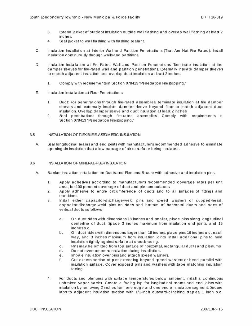
South Londonderry Township - New Municipal & Police Facility B + H 16-019
DUCT INSULATION 230713R - 15
3. Extend jacket of outdoor insulation outside wall flashing and overlap wall flashing at least 2 inches.
4. Seal jacket to wall flashing with flashing sealant.
C. Insulation Installation at Interior Wall and Partition Penetrations (That Are Not Fire Rated): Install insulation continuously through walls and partitions.
D. Insulation Installation at Fire-Rated Wall and Partition Penetrations: Terminate insulation at fire damper sleeves for fire-rated wall and partition penetrations. Externally insulate damper sleeves to match adjacent insulation and overlap duct insulation at least 2 inches.
1. Comply with requirements in Section 078413 "Penetration Firestopping."
E. Insulation Installation at Floor Penetrations:
1. Duct: For penetrations through fire-rated assemblies, terminate insulation at fire damper sleeves and externally insulate damper sleeve beyond floor to match adjacent duct insulation. Overlap damper sleeve and duct insulation at least 2 inches.
2. Seal penetrations through fire-rated assemblies. Comply with requirements in Section 078413 "Penetration Firestopping."
3.5 INSTALLATION OF FLEXIBLE ELASTOMERIC INSULATION
A. Seal longitudinal seams and end joints with manufacturer's recommended adhesive to eliminate openings in insulation that allow passage of air to surface being insulated.
3.6 INSTALLATION OF MINERAL-FIBER INSULATION
A. Blanket Insulation Installation on Ducts and Plenums: Secure with adhesive and insulation pins.
1. Apply adhesives according to manufacturer's recommended coverage rates per unit area, for 100 percent coverage of duct and plenum surfaces.
2. Apply adhesive to entire circumference of ducts and to all surfaces of fittings and transitions.
3. Install either capacitor-discharge-weld pins and speed washers or cupped-head, capacitor-discharge-weld pins on sides and bottom of horizontal ducts and sides of vertical ducts as follows:
a. On duct sides with dimensions 18 inches and smaller, place pins along longitudinal centerline of duct. Space 3 inches maximum from insulation end joints, and 16 inches o.c.
b. On duct sides with dimensions larger than 18 inches, place pins 16 inches o.c. each way, and 3 inches maximum from insulation joints. Install additional pins to hold insulation tightly against surface at cross bracing.
c. Pins may be omitted from top surface of horizontal, rectangular ducts and plenums. d. Do not overcompress insulation during installation. e. Impale insulation over pins and attach speed washers. f. Cut excess portion of pins extending beyond speed washers or bend parallel with
insulation surface. Cover exposed pins and washers with tape matching insulation facing.
4. For ducts and plenums with surface temperatures below ambient, install a continuous unbroken vapor barrier. Create a facing lap for longitudinal seams and end joints with insulation by removing 2 inches from one edge and one end of insulation segment. Secure laps to adjacent insulation section with 1/2-inch outward-clinching staples, 1 inch o.c.
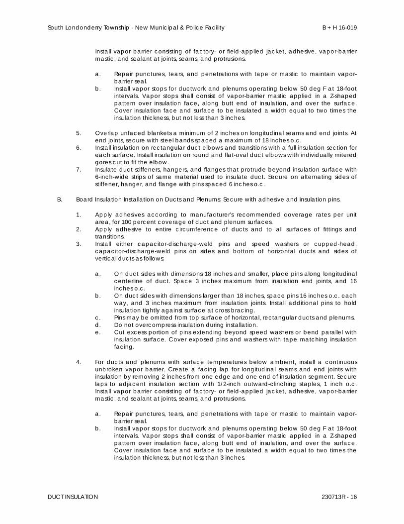
South Londonderry Township - New Municipal & Police Facility B + H 16-019
DUCT INSULATION 230713R - 16
Install vapor barrier consisting of factory- or field-applied jacket, adhesive, vapor-barrier mastic, and sealant at joints, seams, and protrusions.
a. Repair punctures, tears, and penetrations with tape or mastic to maintain vapor-barrier seal.
b. Install vapor stops for ductwork and plenums operating below 50 deg F at 18-foot intervals. Vapor stops shall consist of vapor-barrier mastic applied in a Z-shaped pattern over insulation face, along butt end of insulation, and over the surface. Cover insulation face and surface to be insulated a width equal to two times the insulation thickness, but not less than 3 inches.
5. Overlap unfaced blankets a minimum of 2 inches on longitudinal seams and end joints. At end joints, secure with steel bands spaced a maximum of 18 inches o.c.
6. Install insulation on rectangular duct elbows and transitions with a full insulation section for each surface. Install insulation on round and flat-oval duct elbows with individually mitered gores cut to fit the elbow.
7. Insulate duct stiffeners, hangers, and flanges that protrude beyond insulation surface with 6-inch-wide strips of same material used to insulate duct. Secure on alternating sides of stiffener, hanger, and flange with pins spaced 6 inches o.c.
B. Board Insulation Installation on Ducts and Plenums: Secure with adhesive and insulation pins.
1. Apply adhesives according to manufacturer's recommended coverage rates per unit area, for 100 percent coverage of duct and plenum surfaces.
2. Apply adhesive to entire circumference of ducts and to all surfaces of fittings and transitions.
3. Install either capacitor-discharge-weld pins and speed washers or cupped-head, capacitor-discharge-weld pins on sides and bottom of horizontal ducts and sides of vertical ducts as follows:
a. On duct sides with dimensions 18 inches and smaller, place pins along longitudinal centerline of duct. Space 3 inches maximum from insulation end joints, and 16 inches o.c.
b. On duct sides with dimensions larger than 18 inches, space pins 16 inches o.c. each way, and 3 inches maximum from insulation joints. Install additional pins to hold insulation tightly against surface at cross bracing.
c. Pins may be omitted from top surface of horizontal, rectangular ducts and plenums. d. Do not overcompress insulation during installation. e. Cut excess portion of pins extending beyond speed washers or bend parallel with
insulation surface. Cover exposed pins and washers with tape matching insulation facing.
4. For ducts and plenums with surface temperatures below ambient, install a continuous unbroken vapor barrier. Create a facing lap for longitudinal seams and end joints with insulation by removing 2 inches from one edge and one end of insulation segment. Secure laps to adjacent insulation section with 1/2-inch outward-clinching staples, 1 inch o.c. Install vapor barrier consisting of factory- or field-applied jacket, adhesive, vapor-barrier mastic, and sealant at joints, seams, and protrusions.
a. Repair punctures, tears, and penetrations with tape or mastic to maintain vapor-barrier seal.
b. Install vapor stops for ductwork and plenums operating below 50 deg F at 18-foot intervals. Vapor stops shall consist of vapor-barrier mastic applied in a Z-shaped pattern over insulation face, along butt end of insulation, and over the surface. Cover insulation face and surface to be insulated a width equal to two times the insulation thickness, but not less than 3 inches.
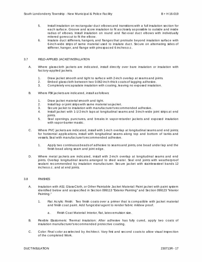
South Londonderry Township - New Municipal & Police Facility B + H 16-019
DUCT INSULATION 230713R - 17
5. Install insulation on rectangular duct elbows and transitions with a full insulation section for each surface. Groove and score insulation to fit as closely as possible to outside and inside radius of elbows. Install insulation on round and flat-oval duct elbows with individually mitered gores cut to fit the elbow.
6. Insulate duct stiffeners, hangers, and flanges that protrude beyond insulation surface with 6-inch-wide strips of same material used to insulate duct. Secure on alternating sides of stiffener, hanger, and flange with pins spaced 6 inches o.c.
3.7 FIELD-APPLIED JACKET INSTALLATION
A. Where glass-cloth jackets are indicated, install directly over bare insulation or insulation with factory-applied jackets.
1. Draw jacket smooth and tight to surface with 2-inch overlap at seams and joints. 2. Embed glass cloth between two 0.062-inch-thick coats of lagging adhesive. 3. Completely encapsulate insulation with coating, leaving no exposed insulation.
B. Where FSK jackets are indicated, install as follows:
1. Draw jacket material smooth and tight. 2. Install lap or joint strips with same material as jacket. 3. Secure jacket to insulation with manufacturer's recommended adhesive. 4. Install jacket with 1-1/2-inch laps at longitudinal seams and 3-inch-wide joint strips at end
joints. 5. Seal openings, punctures, and breaks in vapor-retarder jackets and exposed insulation
with vapor-barrier mastic.
C. Where PVC jackets are indicated, install with 1-inch overlap at longitudinal seams and end joints; for horizontal applications, install with longitudinal seams along top and bottom of tanks and vessels. Seal with manufacturer's recommended adhesive.
1. Apply two continuous beads of adhesive to seams and joints, one bead under lap and the finish bead along seam and joint edge.
D. Where metal jackets are indicated, install with 2-inch overlap at longitudinal seams and end joints. Overlap longitudinal seams arranged to shed water. Seal end joints with weatherproof sealant recommended by insulation manufacturer. Secure jacket with stainless-steel bands 12 inches o.c. and at end joints.
3.8 FINISHES
A. Insulation with ASJ, Glass-Cloth, or Other Paintable Jacket Material: Paint jacket with paint system identified below and as specified in Section 099113 "Exterior Painting" and Section 099123 "Interior Painting."
1. Flat Acrylic Finish: Two finish coats over a primer that is compatible with jacket material and finish coat paint. Add fungicidal agent to render fabric mildew proof.
a. Finish Coat Material: Interior, flat, latex-emulsion size.
B. Flexible Elastomeric Thermal Insulation: After adhesive has fully cured, apply two coats of insulation manufacturer's recommended protective coating.
C. Color: Final color as selected by Architect. Vary first and second coats to allow visual inspection of the completed Work.
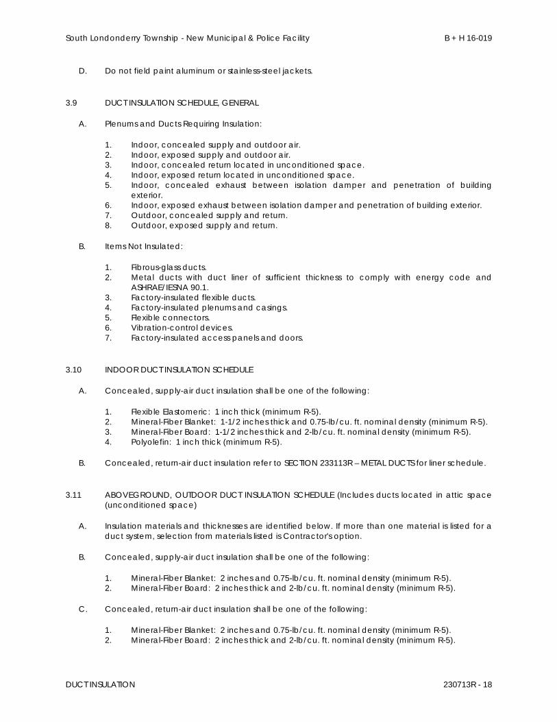
South Londonderry Township - New Municipal & Police Facility B + H 16-019
DUCT INSULATION 230713R - 18
D. Do not field paint aluminum or stainless-steel jackets.
3.9 DUCT INSULATION SCHEDULE, GENERAL
A. Plenums and Ducts Requiring Insulation:
1. Indoor, concealed supply and outdoor air. 2. Indoor, exposed supply and outdoor air. 3. Indoor, concealed return located in unconditioned space. 4. Indoor, exposed return located in unconditioned space. 5. Indoor, concealed exhaust between isolation damper and penetration of building
exterior. 6. Indoor, exposed exhaust between isolation damper and penetration of building exterior. 7. Outdoor, concealed supply and return. 8. Outdoor, exposed supply and return.
B. Items Not Insulated:
1. Fibrous-glass ducts. 2. Metal ducts with duct liner of sufficient thickness to comply with energy code and
ASHRAE/IESNA 90.1. 3. Factory-insulated flexible ducts. 4. Factory-insulated plenums and casings. 5. Flexible connectors. 6. Vibration-control devices. 7. Factory-insulated access panels and doors.
3.10 INDOOR DUCT INSULATION SCHEDULE
A. Concealed, supply-air duct insulation shall be one of the following:
1. Flexible Elastomeric: 1 inch thick (minimum R-5). 2. Mineral-Fiber Blanket: 1-1/2 inches thick and 0.75-lb/cu. ft. nominal density (minimum R-5). 3. Mineral-Fiber Board: 1-1/2 inches thick and 2-lb/cu. ft. nominal density (minimum R-5). 4. Polyolefin: 1 inch thick (minimum R-5).
B. Concealed, return-air duct insulation refer to SECTION 233113R – METAL DUCTS for liner schedule.
3.11 ABOVEGROUND, OUTDOOR DUCT INSULATION SCHEDULE (Includes ducts located in attic space (unconditioned space)
A. Insulation materials and thicknesses are identified below. If more than one material is listed for a duct system, selection from materials listed is Contractor's option.
B. Concealed, supply-air duct insulation shall be one of the following:
1. Mineral-Fiber Blanket: 2 inches and 0.75-lb/cu. ft. nominal density (minimum R-5). 2. Mineral-Fiber Board: 2 inches thick and 2-lb/cu. ft. nominal density (minimum R-5).
C. Concealed, return-air duct insulation shall be one of the following:
1. Mineral-Fiber Blanket: 2 inches and 0.75-lb/cu. ft. nominal density (minimum R-5). 2. Mineral-Fiber Board: 2 inches thick and 2-lb/cu. ft. nominal density (minimum R-5).
South Londonderry Township - New Municipal & Police Facility B + H 16-019
DUCT INSULATION 230713R - 19
3.12 INDOOR, FIELD-APPLIED JACKET SCHEDULE
A. Install jacket over insulation material. For insulation with factory-applied jacket, install the field-applied jacket over the factory-applied jacket.
B. If more than one material is listed, selection from materials listed is Contractor's option.
C. Ducts and Plenums, Concealed:
1. None.
D. Ducts and Plenums, Exposed:
1. None.
3.13 OUTDOOR, FIELD-APPLIED JACKET SCHEDULE
A. Install jacket over insulation material. For insulation with factory-applied jacket, install the field-applied jacket over the factory-applied jacket.
B. If more than one material is listed, selection from materials listed is Contractor's option.
C. Ducts and Plenums, Concealed:
1. Aluminum, Smooth: 0.020 inch thick.
D. Ducts and Plenums, Exposed, up to 48 Inches in Diameter or with Flat Surfaces up to 72 Inches:
1. Aluminum, Smooth: 0.024 inch thick.
END OF SECTION 230713R

South Londonderry Township - New Municipal & Police Facility B + H 16-019
HVAC PIPING INSULATION 230719 - 1
SECTION 230719 - HVAC PIPING INSULATION
PART 1 - GENERAL
1.1 RELATED DOCUMENTS
A. Drawings and general provisions of the Contract, including General and Supplementary Conditions and Division 01 Specification Sections, apply to this Section.
1.2 SUMMARY
A. Section includes insulating the following HVAC piping systems:
1. Condensate drain piping, indoors. 2. Refrigerant suction and hot-gas piping, indoors and outdoors.
1.3 ACTION SUBMITTALS
A. Product Data: For each type of product indicated. Include thermal conductivity, water-vapor permeance thickness, and jackets (both factory and field applied if any).
1.4 DELIVERY, STORAGE, AND HANDLING
A. Packaging: Insulation material containers shall be marked by manufacturer with appropriate ASTM standard designation, type and grade, and maximum use temperature.
1.5 SCHEDULING
A. Schedule insulation application after pressure testing systems and, where required, after installing and testing heat tracing. Insulation application may begin on segments that have satisfactory test results.
B. Complete installation and concealment of plastic materials as rapidly as possible in each area of construction.
PART 2 - PRODUCTS
2.1 INSULATION MATERIALS
A. Comply with requirements in "Piping Insulation Schedule, General," "Indoor Piping Insulation Schedule," "Outdoor, Aboveground Piping Insulation Schedule," and "Outdoor, Underground Piping Insulation Schedule" articles for where insulating materials shall be applied.
B. Products shall not contain asbestos, lead, mercury, or mercury compounds.
C. Flexible Elastomeric Insulation: Closed-cell, sponge- or expanded-rubber materials. Comply with ASTM C 534, Type I for tubular materials.
South Londonderry Township - New Municipal & Police Facility B + H 16-019
HVAC PIPING INSULATION 230719 - 2
1. Manufacturers: Subject to compliance with requirements, provide products by one of the following:
a. Aeroflex USA, Inc. b. Armacell LLC. c. K-Flex USA.
D. Polyolefin: Unicellular, polyethylene thermal plastic insulation. Comply with ASTM C 534 or ASTM C 1427, Type I, Grade 1 for tubular materials and Type II, Grade 1 for sheet materials.
1. Manufacturers: Subject to compliance with requirements, provide products by one of the following:
a. Armacell LLC. b. Nomaco Insulation.
2.2 ADHESIVES
A. Materials shall be compatible with insulation materials, jackets, and substrates and for bonding insulation to itself and to surfaces to be insulated unless otherwise indicated.
B. Flexible Elastomeric and Polyolefin Adhesive: Comply with MIL-A-24179A, Type II, Class I.
1. Manufacturers: Subject to compliance with requirements, provide products by one of the following:
a. Aeroflex USA, Inc. b. Armacell LLC. c. Foster Brand; H. B. Fuller Construction Products. d. K-Flex USA.
2.3 SECUREMENTS
A. Bands:
1. Stainless Steel: ASTM A 167 or ASTM A 240/A 240M, Type 304 or Type 316; 0.015 inch thick, 1/2 inch 3/4 inch wide with wing seal or closed seal.
2. Aluminum: ASTM B 209, Alloy 3003, 3005, 3105, or 5005; Temper H-14, 0.020 inch thick, 1/2 inch or 3/4 inch wide with wing seal or closed seal.
3. Springs: Twin spring set constructed of stainless steel with ends flat and slotted to accept metal bands. Spring size determined by manufacturer for application.
B. Staples: Outward-clinching insulation staples, nominal 3/4-inch-wide, stainless steel or Monel.
C. Wire: 0.080-inch nickel-copper alloy 0.062-inch soft-annealed, stainless steel or 0.062-inch soft-annealed, galvanized steel.
South Londonderry Township - New Municipal & Police Facility B + H 16-019
HVAC PIPING INSULATION 230719 - 3
PART 3 - EXECUTION
3.1 EXAMINATION
A. Examine substrates and conditions for compliance with requirements for installation tolerances and other conditions affecting performance of insulation application.
1. Verify that systems to be insulated have been tested and are free of defects. 2. Verify that surfaces to be insulated are clean and dry. 3. Proceed with installation only after unsatisfactory conditions have been corrected.
3.2 PREPARATION
A. Surface Preparation: Clean and dry surfaces to receive insulation. Remove materials that will adversely affect insulation application.
B. Surface Preparation: Clean and prepare surfaces to be insulated. Before insulating, apply a corrosion coating to insulated surfaces as follows:
1. Stainless Steel: Coat 300 series stainless steel with an epoxy primer 5 mils thick and an epoxy finish 5 mils thick if operating in a temperature range between 140 and 300 deg F. Consult coating manufacturer for appropriate coating materials and application methods for operating temperature range.
2. Carbon Steel: Coat carbon steel operating at a service temperature between 32 and 300 deg F with an epoxy coating. Consult coating manufacturer for appropriate coating materials and application methods for operating temperature range.
C. Coordinate insulation installation with the trade installing heat tracing. Comply with requirements for heat tracing that apply to insulation.
D. Mix insulating cements with clean potable water; if insulating cements are to be in contact with stainless-steel surfaces, use demineralized water.
3.3 GENERAL INSTALLATION REQUIREMENTS
A. Install insulation materials, accessories, and finishes with smooth, straight, and even surfaces; free of voids throughout the length of piping including fittings, valves, and specialties.
B. Install insulation materials, forms, vapor barriers or retarders, jackets, and thicknesses required for each item of pipe system as specified in insulation system schedules.
C. Install accessories compatible with insulation materials and suitable for the service. Install accessories that do not corrode, soften, or otherwise attack insulation or jacket in either wet or dry state.
D. Install insulation with longitudinal seams at top and bottom of horizontal runs.
E. Install multiple layers of insulation with longitudinal and end seams staggered.
F. Do not weld brackets, clips, or other attachment devices to piping, fittings, and specialties.
G. Keep insulation materials dry during application and finishing.
South Londonderry Township - New Municipal & Police Facility B + H 16-019
HVAC PIPING INSULATION 230719 - 4
H. Install insulation with tight longitudinal seams and end joints. Bond seams and joints with adhesive recommended by insulation material manufacturer.
I. Install insulation with least number of joints practical.
J. Where vapor barrier is indicated, seal joints, seams, and penetrations in insulation at hangers, supports, anchors, and other projections with vapor-barrier mastic.
1. Install insulation continuously through hangers and around anchor attachments. 2. For insulation application where vapor barriers are indicated, extend insulation on anchor
legs from point of attachment to supported item to point of attachment to structure. Taper and seal ends at attachment to structure with vapor-barrier mastic.
3. Install insert materials and install insulation to tightly join the insert. Seal insulation to insulation inserts with adhesive or sealing compound recommended by insulation material manufacturer.
4. Cover inserts with jacket material matching adjacent pipe insulation. Install shields over jacket, arranged to protect jacket from tear or puncture by hanger, support, and shield.
K. Apply adhesives, mastics, and sealants at manufacturer's recommended coverage rate and wet and dry film thicknesses.
L. Cut insulation in a manner to avoid compressing insulation more than 75 percent of its nominal thickness.
M. Finish installation with systems at operating conditions. Repair joint separations and cracking due to thermal movement.
N. Repair damaged insulation facings by applying same facing material over damaged areas. Extend patches at least 4 inches beyond damaged areas. Adhere, staple, and seal patches similar to butt joints.
O. For above-ambient services, do not install insulation to the following:
1. Vibration-control devices. 2. Testing agency labels and stamps. 3. Nameplates and data plates. 4. Manholes. 5. Handholes. 6. Cleanouts.
3.4 PENETRATIONS
A. Insulation Installation at Roof Penetrations: Install insulation continuously through roof penetrations.
1. Seal penetrations with flashing sealant. 2. For applications requiring only indoor insulation, terminate insulation above roof surface
and seal with joint sealant. For applications requiring indoor and outdoor insulation, install insulation for outdoor applications tightly joined to indoor insulation ends. Seal joint with joint sealant.
3. Extend jacket of outdoor insulation outside roof flashing at least 2 inches below top of roof flashing.
4. Seal jacket to roof flashing with flashing sealant.
B. Insulation Installation at Underground Exterior Wall Penetrations: Terminate insulation flush with sleeve seal. Seal terminations with flashing sealant.
South Londonderry Township - New Municipal & Police Facility B + H 16-019
HVAC PIPING INSULATION 230719 - 5
C. Insulation Installation at Aboveground Exterior Wall Penetrations: Install insulation continuously through wall penetrations.
1. Seal penetrations with flashing sealant. 2. For applications requiring only indoor insulation, terminate insulation inside wall surface and
seal with joint sealant. For applications requiring indoor and outdoor insulation, install insulation for outdoor applications tightly joined to indoor insulation ends. Seal joint with joint sealant.
3. Extend jacket of outdoor insulation outside wall flashing and overlap wall flashing at least 2 inches.
4. Seal jacket to wall flashing with flashing sealant.
D. Insulation Installation at Interior Wall and Partition Penetrations (That Are Not Fire Rated): Install insulation continuously through walls and partitions.
E. Insulation Installation at Fire-Rated Wall and Partition Penetrations: Install insulation continuously through penetrations of fire-rated walls and partitions.
1. Comply with requirements in Section 078413 "Penetration Firestopping" for firestopping and fire-resistive joint sealers.
F. Insulation Installation at Floor Penetrations:
1. Pipe: Install insulation continuously through floor penetrations. 2. Seal penetrations through fire-rated assemblies. Comply with requirements in
Section 078413 "Penetration Firestopping."
3.5 INSTALLATION OF FLEXIBLE ELASTOMERIC INSULATION
A. Seal longitudinal seams and end joints with manufacturer's recommended adhesive to eliminate openings in insulation that allow passage of air to surface being insulated.
B. Insulation Installation on Pipe Flanges:
1. Install pipe insulation to outer diameter of pipe flange. 2. Make width of insulation section same as overall width of flange and bolts, plus twice the
thickness of pipe insulation. 3. Fill voids between inner circumference of flange insulation and outer circumference of
adjacent straight pipe segments with cut sections of sheet insulation of same thickness as pipe insulation.
4. Secure insulation to flanges and seal seams with manufacturer's recommended adhesive to eliminate openings in insulation that allow passage of air to surface being insulated.
C. Insulation Installation on Pipe Fittings and Elbows:
1. Install mitered sections of pipe insulation. 2. Secure insulation materials and seal seams with manufacturer's recommended adhesive
to eliminate openings in insulation that allow passage of air to surface being insulated.
D. Insulation Installation on Valves and Pipe Specialties:
1. Install preformed valve covers manufactured of same material as pipe insulation when available.
2. When preformed valve covers are not available, install cut sections of pipe and sheet insulation to valve body. Arrange insulation to permit access to packing and to allow valve operation without disturbing insulation.
South Londonderry Township - New Municipal & Police Facility B + H 16-019
HVAC PIPING INSULATION 230719 - 6
3. Install insulation to flanges as specified for flange insulation application. 4. Secure insulation to valves and specialties and seal seams with manufacturer's
recommended adhesive to eliminate openings in insulation that allow passage of air to surface being insulated.
3.6 INSTALLATION OF POLYOLEFIN INSULATION
A. Insulation Installation on Straight Pipes and Tubes:
1. Seal split-tube longitudinal seams and end joints with manufacturer's recommended adhesive to eliminate openings in insulation that allow passage of air to surface being insulated.
B. Insulation Installation on Pipe Flanges:
1. Install pipe insulation to outer diameter of pipe flange. 2. Make width of insulation section same as overall width of flange and bolts, plus twice the
thickness of pipe insulation. 3. Fill voids between inner circumference of flange insulation and outer circumference of
adjacent straight pipe segments with cut sections of polyolefin sheet insulation of same thickness as pipe insulation.
4. Secure insulation to flanges and seal seams with manufacturer's recommended adhesive to eliminate openings in insulation that allow passage of air to surface being insulated.
C. Insulation Installation on Pipe Fittings and Elbows:
1. Install mitered sections of polyolefin pipe insulation. 2. Secure insulation materials and seal seams with manufacturer's recommended adhesive
to eliminate openings in insulation that allow passage of air to surface being insulated.
D. Insulation Installation on Valves and Pipe Specialties:
1. Install cut sections of polyolefin pipe and sheet insulation to valve body. 2. Arrange insulation to permit access to packing and to allow valve operation without
disturbing insulation. 3. Install insulation to flanges as specified for flange insulation application. 4. Secure insulation to valves and specialties, and seal seams with manufacturer's
recommended adhesive to eliminate openings in insulation that allow passage of air to surface being insulated.
3.7 FINISHES
A. Flexible Elastomeric Thermal Insulation: After adhesive has fully cured, apply two coats of insulation manufacturer's recommended protective coating.
3.8 FIELD QUALITY CONTROL
A. Testing Agency: Owner will engage a qualified testing agency to perform tests and inspections.
B. Perform tests and inspections.
C. All insulation applications will be considered defective Work if sample inspection reveals noncompliance with requirements.
South Londonderry Township - New Municipal & Police Facility B + H 16-019
HVAC PIPING INSULATION 230719 - 7
3.9 PIPING INSULATION SCHEDULE, GENERAL
A. Acceptable preformed pipe and tubular insulation materials and thicknesses are identified for each piping system and pipe size range. If more than one material is listed for a piping system, selection from materials listed is Contractor's option.
B. Items Not Insulated: Unless otherwise indicated, do not install insulation on the following:
1. Drainage piping located in crawl spaces. 2. Underground piping. 3. Chrome-plated pipes and fittings unless there is a potential for personnel injury.
3.10 INDOOR PIPING INSULATION SCHEDULE
A. Condensate and Equipment Drain Water below 60 Deg F:
1. All Pipe Sizes: Insulation shall be one of the following:
a. Flexible Elastomeric: 1 inch thick. b. Polyolefin: 1 inch thick.
B. Refrigerant Suction and Hot-Gas Piping:
1. All Pipe Sizes: Insulation shall be one of the following:
a. Flexible Elastomeric: 1 inch thick. b. Polyolefin: 1 inch thick.
C. Refrigerant Suction and Hot-Gas Flexible Tubing:
1. All Pipe Sizes: Insulation shall be one of the following:
a. Flexible Elastomeric: 1 inch thick. b. Polyolefin: 1 inch thick.
3.11 OUTDOOR, ABOVEGROUND PIPING INSULATION SCHEDULE
A. Refrigerant Suction and Hot-Gas Piping:
1. All Pipe Sizes: Insulation shall be one of the following:
a. Flexible Elastomeric: 2 inches thick. b. Polyolefin: 2 inches thick.
B. Refrigerant Suction and Hot-Gas Flexible Tubing:
1. All Pipe Sizes: Insulation shall be one of the following:
a. Flexible Elastomeric: 2 inches thick. b. Polyolefin: 2 inches thick.
END OF SECTION 230719
South Londonderry Township - New Municipal & Police Facility B + H 16-019
REFRIGERANT PIPING 232300 - 1
SECTION 232300 - REFRIGERANT PIPING
PART 1 - GENERAL
1.1 RELATED DOCUMENTS
A. Drawings and general provisions of the Contract, including General and Supplementary Conditions and Division 01 Specification Sections, apply to this Section.
1.2 SUMMARY
A. Section Includes:
1. Refrigerant pipes and fittings. 2. Refrigerants.
1.3 ACTION SUBMITTALS
A. Product Data: For each type of valve, refrigerant piping, and piping specialty.
B. Shop Drawings:
1. Show layout of refrigerant piping and specialties, including pipe, tube, and fitting sizes; flow capacities; valve arrangements and locations; slopes of horizontal runs; oil traps; double risers; wall and floor penetrations; and equipment connection details.
1.4 INFORMATIONAL SUBMITTALS
A. Welding certificates.
B. Field quality-control reports.
1.5 CLOSEOUT SUBMITTALS
A. Operation and Maintenance Data: For refrigerant valves and piping specialties to include in maintenance manuals.
1.6 QUALITY ASSURANCE
A. Welding Qualifications: Qualify procedures and personnel according to 2010 ASME Boiler and Pressure Vessel Code: Section IX, "Welding and Brazing Qualifications."
B. Comply with ASHRAE 15, "Safety Code for Refrigeration Systems."
C. Comply with ASME B31.5, "Refrigeration Piping and Heat Transfer Components."
South Londonderry Township - New Municipal & Police Facility B + H 16-019
REFRIGERANT PIPING 232300 - 2
1.7 PRODUCT STORAGE AND HANDLING
A. Store piping with end caps in place to ensure that piping interior and exterior are clean when installed.
PART 2 - PRODUCTS
2.1 PERFORMANCE REQUIREMENTS
A. Line Test Pressure for Refrigerant R-410A:
1. Suction Lines for Air-Conditioning Applications: 300 psig. 2. Suction Lines for Heat-Pump Applications: 535 psig. 3. Hot-Gas and Liquid Lines: 535 psig.
2.2 COPPER TUBE AND FITTINGS
A. Copper Tube: ASTM B 280, Type ACR.
B. Wrought-Copper Fittings: ASME B16.22.
C. Wrought-Copper Unions: ASME B16.22.
D. Solder Filler Metals: ASTM B 32. Use 95-5 tin antimony or alloy HB solder to join copper socket fittings on copper pipe.
E. Brazing Filler Metals: AWS A5.8/A5.8M.
F. Flexible Connectors:
1. Body: Tin-bronze bellows with woven, flexible, tinned-bronze-wire-reinforced protective jacket.
2. End Connections: Socket ends. 3. Offset Performance: Capable of minimum 3/4-inch misalignment in minimum 7-inch-long
assembly. 4. Working Pressure Rating: Factory test at minimum 500 psig. 5. Maximum Operating Temperature: 250 deg F.
2.3 REFRIGERANTS
A. ASHRAE 34, R-410A: Pentafluoroethane/Difluoromethane.
PART 3 - EXECUTION
3.1 PIPING APPLICATIONS FOR REFRIGERANT R-410A
A. Suction Lines NPS 1-1/2 and Smaller for Conventional Air-Conditioning Applications: Copper, Type ACR, annealed-temper tubing and wrought-copper fittings with brazed joints.
South Londonderry Township - New Municipal & Police Facility B + H 16-019
REFRIGERANT PIPING 232300 - 3
B. Hot-Gas and Liquid Lines: Copper, Type ACR, annealed- or drawn-temper tubing and wrought-copper fittings with brazed joints.
3.2 PIPING INSTALLATION
A. Drawing plans indicate general location and arrangement of piping systems. Install piping per manufacturer’s installation manual.
B. Install refrigerant piping according to ASHRAE 15 and manufacturer’s recommendations.
C. Install piping in concealed locations unless otherwise indicated and except in equipment rooms and service areas.
D. Install piping indicated to be exposed and piping in equipment rooms and service areas at right angles or parallel to building walls. Diagonal runs are prohibited unless specifically indicated otherwise.
E. Install piping above accessible ceilings to allow sufficient space for ceiling panel removal.
F. Install piping adjacent to machines to allow service and maintenance.
G. Install piping free of sags and bends.
H. Install fittings for changes in direction and branch connections.
I. Select system components with pressure rating equal to or greater than system operating pressure.
J. Install piping as short and direct as possible, with a minimum number of joints, elbows, and fittings. Coordinate with ductwork and other systems.
K. Arrange piping to allow inspection and service of refrigeration equipment. Install valves and specialties in accessible locations to allow for service and inspection. Install access doors or panels as specified in Section 083113 "Access Doors and Frames" if valves or equipment requiring maintenance is concealed behind finished surfaces.
L. Install refrigerant piping in protective conduit where installed belowground.
M. Install refrigerant piping in rigid or flexible conduit in locations where exposed to mechanical injury.
N. When brazing, remove solenoid-valve coils and sight glasses; also remove valve stems, seats, and packing, and accessible internal parts of refrigerant specialties. Do not apply heat near expansion-valve bulb.
O. Install piping with adequate clearance between pipe and adjacent walls and hangers or between pipes for insulation installation.
P. Identify refrigerant piping and valves according to Section 230553 "Identification for HVAC Piping and Equipment."
Q. Install sleeves for piping penetrations of walls, ceilings, and floors. Comply with requirements for sleeves specified in Section 230517 "Sleeves and Sleeve Seals for HVAC Piping."
South Londonderry Township - New Municipal & Police Facility B + H 16-019
REFRIGERANT PIPING 232300 - 4
R. Install sleeve seals for piping penetrations of concrete walls and slabs. Comply with requirements for sleeve seals specified in Section 230517 "Sleeves and Sleeve Seals for HVAC Piping."
S. Install escutcheons for piping penetrations of walls, ceilings, and floors. Comply with requirements for escutcheons specified in Section 230518 "Escutcheons for HVAC Piping."
3.3 PIPE JOINT CONSTRUCTION
A. Ream ends of pipes and tubes and remove burrs. Bevel plain ends of steel pipe.
B. Remove scale, slag, dirt, and debris from inside and outside of pipe and fittings before assembly.
C. Brazed Joints: Construct joints according to AWS's "Brazing Handbook," Chapter "Pipe and Tube."
1. Use Type BCuP (copper-phosphorus) alloy for joining copper socket fittings with copper pipe.
2. Use Type BAg (cadmium-free silver) alloy for joining copper with bronze or steel.
3.4 HANGERS AND SUPPORTS
A. Comply with requirements for pipe hangers and supports specified in Section 230529 "Hangers and Supports for HVAC Piping and Equipment."
B. Install hangers for copper tubing with the following maximum spacing and minimum rod diameters:
1. NPS 1/2: Maximum span, 60 inches; minimum rod, 1/4 inch. 2. NPS 5/8: Maximum span, 60 inches; minimum rod, 1/4 inch. 3. NPS 1: Maximum span, 72 inches; minimum rod, 1/4 inch.
C. Support multifloor vertical runs at least at each floor.
3.5 FIELD QUALITY CONTROL
A. Perform the following tests and inspections:
1. Comply with ASME B31.5, Chapter VI. 2. Test refrigerant piping, specialties, and receivers. Isolate compressor, condenser,
evaporator, and safety devices from test pressure if they are not rated above the test pressure.
3. Test high- and low-pressure side piping of each system separately at not less than the pressures indicated in "Performance Requirements" Article.
a. Fill system with nitrogen to the required test pressure. b. System shall maintain test pressure at the manifold gage throughout duration of test. c. Test joints and fittings with electronic leak detector or by brushing a small amount of
soap and glycerin solution over joints. d. Remake leaking joints using new materials, and retest until satisfactory results are
achieved.
B. Prepare test and inspection reports.
South Londonderry Township - New Municipal & Police Facility B + H 16-019
REFRIGERANT PIPING 232300 - 5
3.6 SYSTEM CHARGING
A. Charge system using the following procedures:
1. Install core in filter dryers after leak test but before evacuation. 2. Evacuate entire refrigerant system with a vacuum pump to 500 micrometers. If vacuum
holds for 12 hours, system is ready for charging. 3. Break vacuum with refrigerant gas, allowing pressure to build up to 2 psig. 4. Charge system with a new filter-dryer core in charging line.
3.7 ADJUSTING
A. Adjust thermostatic expansion valve to obtain proper evaporator superheat.
B. Adjust high- and low-pressure switch settings to avoid short cycling in response to fluctuating suction pressure.
C. Adjust set-point temperature of air-conditioning or chilled-water controllers to the system design temperature.
D. Perform the following adjustments before operating the refrigeration system, according to manufacturer's written instructions:
1. Open shutoff valves in condenser water circuit. 2. Verify that compressor oil level is correct. 3. Open compressor suction and discharge valves. 4. Open refrigerant valves except bypass valves that are used for other purposes. 5. Check open compressor-motor alignment and verify lubrication for motors and bearings.
E. Replace core of replaceable filter dryer after system has been adjusted and after design flow rates and pressures are established.
END OF SECTION 232300

South Londonderry Township - New Municipal & Police Facility B + H 16-019
METAL DUCTS 233113R - 1
SECTION 233113R - METAL DUCTS
PART 1 - GENERAL
1.1 RELATED DOCUMENTS
A. Drawings and general provisions of the Contract, including General and Supplementary Conditions and Division 01 Specification Sections, apply to this Section.
1.2 SUMMARY
A. Section Includes:
1. Single-wall rectangular ducts and fittings. 2. Double-wall rectangular ducts and fittings. 3. Single-wall round ducts and fittings. 4. Double-wall round ducts and fittings. 5. Sheet metal materials. 6. Duct liner. 7. Sealant and gaskets. 8. Hangers and supports. 9. Seismic-restraint devices.
B. Related Sections:
1. Section 230593 "Testing, Adjusting, and Balancing for HVAC" for testing, adjusting, and balancing requirements for metal ducts.
2. Section 233300 "Air Duct Accessories" for dampers, sound-control devices, duct-mounting access doors and panels, turning vanes, and flexible ducts.
1.3 PERFORMANCE REQUIREMENTS
A. Delegated Duct Design: Duct construction, including sheet metal thicknesses, seam and joint construction, reinforcements, and hangers and supports, shall comply with SMACNA's "HVAC Duct Construction Standards - Metal and Flexible" and performance requirements and design criteria indicated in "Duct Schedule" Article.
B. Structural Performance: Duct hangers and supports shall withstand the effects of gravity loads and stresses within limits and under conditions described in SMACNA's "HVAC Duct Construction Standards - Metal and Flexible."
C. Airstream Surfaces: Surfaces in contact with the airstream shall comply with requirements in ASHRAE 62.1.
1.4 ACTION SUBMITTALS
A. Product Data: For each type of the following products:
1. Liners and adhesives. 2. Sealants and gaskets.
South Londonderry Township - New Municipal & Police Facility B + H 16-019
METAL DUCTS 233113R - 2
3. Seismic-restraint devices.
B. LEED Submittals:
1. Product Data for Prerequisite IEQ 1: Documentation indicating that duct systems comply with ASHRAE 62.1, Section 5 - "Systems and Equipment."
2. Product Data for Prerequisite EA 2: Documentation indicating that duct systems comply with ASHRAE/IESNA 90.1, Section 6.4.4 - "HVAC System Construction and Insulation."
3. Leakage Test Report for Prerequisite EA 2: Documentation of work performed for compliance with ASHRAE/IESNA 90.1, Section 6.4.4.2.2 - "Duct Leakage Tests."
4. Duct-Cleaning Test Report for Prerequisite IEQ 1: Documentation of work performed for compliance with ASHRAE 62.1, Section 7.2.4 - "Ventilation System Start-up."
5. Product Data for Credit IEQ 4.1: For adhesives and sealants, documentation including printed statement of VOC content.
6. Laboratory Test Reports for Credit IEQ 4: For adhesives and sealants, documentation indicating that products comply with the testing and product requirements of the California Department of Health Services' "Standard Practice for the Testing of Volatile Organic Emissions from Various Sources Using Small-Scale Environmental Chambers."
C. Shop Drawings:
1. Fabrication, assembly, and installation, including plans, elevations, sections, components, and attachments to other work.
2. Factory- and shop-fabricated ducts and fittings. 3. Duct layout indicating sizes, configuration, liner material, and static-pressure classes. 4. Elevation of top of ducts. 5. Dimensions of main duct runs from building grid lines. 6. Fittings. 7. Reinforcement and spacing. 8. Seam and joint construction. 9. Penetrations through fire-rated and other partitions. 10. Equipment installation based on equipment being used on Project. 11. Locations for duct accessories, including dampers, turning vanes, and access doors and
panels. 12. Hangers and supports, including methods for duct and building attachment and vibration
isolation.
D. Delegated-Design Submittal:
1. Sheet metal thicknesses. 2. Joint and seam construction and sealing. 3. Reinforcement details and spacing. 4. Materials, fabrication, assembly, and spacing of hangers and supports.
1.5 INFORMATIONAL SUBMITTALS
A. Coordination Drawings: Plans, drawn to scale, on which the following items are shown and coordinated with each other, using input from installers of the items involved:
1. Duct installation in congested spaces, indicating coordination with general construction, building components, and other building services. Indicate proposed changes to duct layout.
2. Suspended ceiling components. 3. Structural members to which duct will be attached. 4. Size and location of initial access modules for acoustical tile. 5. Penetrations of smoke barriers and fire-rated construction.
South Londonderry Township - New Municipal & Police Facility B + H 16-019
METAL DUCTS 233113R - 3
6. Items penetrating finished ceiling including the following:
a. Lighting fixtures. b. Air outlets and inlets. c. Speakers. d. Sprinklers. e. Access panels. f. Perimeter moldings.
B. Welding certificates.
C. Field quality-control reports.
1.6 QUALITY ASSURANCE
A. Welding Qualifications: Qualify procedures and personnel according to AWS D1.1/D1.1M, "Structural Welding Code - Steel," for hangers and supports,. AWS D1.2/D1.2M, "Structural Welding Code - Aluminum," for aluminum supports, and AWS D9.1M/D9.1, "Sheet Metal Welding Code," for duct joint and seam welding.
B. Welding Qualifications: Qualify procedures and personnel according to the following:
1. AWS D1.1/D1.1M, "Structural Welding Code - Steel," for hangers and supports. 2. AWS D1.2/D1.2M, "Structural Welding Code - Aluminum," for aluminum supports. 3. AWS D9.1M/D9.1, "Sheet Metal Welding Code," for duct joint and seam welding.
C. ASHRAE Compliance: Applicable requirements in ASHRAE 62.1, Section 5 - "Systems and Equipment" and Section 7 - "Construction and System Start-up."
D. ASHRAE/IESNA Compliance: Applicable requirements in ASHRAE/IESNA 90.1, Section 6.4.4 - "HVAC System Construction and Insulation."
PART 2 - PRODUCTS
2.1 SINGLE-WALL RECTANGULAR DUCTS AND FITTINGS
A. General Fabrication Requirements: Comply with SMACNA's "HVAC Duct Construction Standards - Metal and Flexible" based on indicated static-pressure class unless otherwise indicated.
B. Transverse Joints: Select joint types and fabricate according to SMACNA's "HVAC Duct Construction Standards - Metal and Flexible," Figure 2-1, "Rectangular Duct/Transverse Joints," for static-pressure class, applicable sealing requirements, materials involved, duct-support intervals, and other provisions in SMACNA's "HVAC Duct Construction Standards - Metal and Flexible."
C. Longitudinal Seams: Select seam types and fabricate according to SMACNA's "HVAC Duct Construction Standards - Metal and Flexible," Figure 2-2, "Rectangular Duct/Longitudinal Seams," for static-pressure class, applicable sealing requirements, materials involved, duct-support intervals, and other provisions in SMACNA's "HVAC Duct Construction Standards - Metal and Flexible."
D. Elbows, Transitions, Offsets, Branch Connections, and Other Duct Construction: Select types and fabricate according to SMACNA's "HVAC Duct Construction Standards - Metal and Flexible," Chapter 4, "Fittings and Other Construction," for static-pressure class, applicable sealing
South Londonderry Township - New Municipal & Police Facility B + H 16-019
METAL DUCTS 233113R - 4
requirements, materials involved, duct-support intervals, and other provisions in SMACNA's "HVAC Duct Construction Standards - Metal and Flexible."
2.2 SINGLE-WALL ROUND DUCTS AND FITTINGS
A. General Fabrication Requirements: Comply with SMACNA's "HVAC Duct Construction Standards - Metal and Flexible," Chapter 3, "Round, Oval, and Flexible Duct," based on indicated static-pressure class unless otherwise indicated.
1. Manufacturers: Subject to compliance with requirements, provide products by one of the following:
a. Ductmate Industries, Inc. b. Elgen Manufacturing. c. Linx Industries (formerly Lindab). d. McGill AirFlow LLC. e. MKT Metal Manufacturing. f. SEMCO LLC. g. Sheet Metal Connectors, Inc. h. Spiral Manufacturing Co., Inc. i. Stamped Fittings Inc.
B. Flat-Oval Ducts: Indicated dimensions are the duct width (major dimension) and diameter of the round sides connecting the flat portions of the duct (minor dimension).
C. Transverse Joints: Select joint types and fabricate according to SMACNA's "HVAC Duct Construction Standards - Metal and Flexible," Figure 3-1, "Round Duct Transverse Joints," for static-pressure class, applicable sealing requirements, materials involved, duct-support intervals, and other provisions in SMACNA's "HVAC Duct Construction Standards - Metal and Flexible."
1. Transverse Joints in Ducts Larger Than 60 Inches in Diameter: Flanged.
D. Longitudinal Seams: Select seam types and fabricate according to SMACNA's "HVAC Duct Construction Standards - Metal and Flexible," Figure 3-2, "Round Duct Longitudinal Seams," for static-pressure class, applicable sealing requirements, materials involved, duct-support intervals, and other provisions in SMACNA's "HVAC Duct Construction Standards - Metal and Flexible."
1. Fabricate round ducts larger than 90 inches in diameter with butt-welded longitudinal seams.
2. Fabricate flat-oval ducts larger than 72 inches in width (major dimension) with butt-welded longitudinal seams.
E. Tees and Laterals: Select types and fabricate according to SMACNA's "HVAC Duct Construction Standards - Metal and Flexible," Figure 3-5, "90 Degree Tees and Laterals," and Figure 3-6, "Conical Tees," for static-pressure class, applicable sealing requirements, materials involved, duct-support intervals, and other provisions in SMACNA's "HVAC Duct Construction Standards - Metal and Flexible."
2.3 SHEET METAL MATERIALS
A. General Material Requirements: Comply with SMACNA's "HVAC Duct Construction Standards - Metal and Flexible" for acceptable materials, material thicknesses, and duct construction methods unless otherwise indicated. Sheet metal materials shall be free of pitting, seam marks, roller marks, stains, discolorations, and other imperfections.
South Londonderry Township - New Municipal & Police Facility B + H 16-019
METAL DUCTS 233113R - 5
B. Galvanized Sheet Steel: Comply with ASTM A 653/A 653M.
1. Galvanized Coating Designation: G90. 2. Finishes for Surfaces Exposed to View: Mill phosphatized.
C. PVC-Coated, Galvanized Sheet Steel: Comply with ASTM A 653/A 653M.
1. Galvanized Coating Designation: G90. 2. Minimum Thickness for Factory-Applied PVC Coating: 4 mils thick on sheet metal surface of
ducts and fittings exposed to corrosive conditions, and minimum 1 mil thick on opposite surface.
3. Coating Materials: Acceptable to authorities having jurisdiction for use on ducts listed and labeled by an NRTL for compliance with UL 181, Class 1.
D. Stainless-Steel Sheets: Comply with ASTM A 480/A 480M, Type 304 or 316, as indicated in the "Duct Schedule" Article; cold rolled, annealed, sheet. Exposed surface finish shall be No. 2B, No. 2D, No. 3, or No. 4 as indicated in the "Duct Schedule" Article.
E. Tie Rods: Galvanized steel, 1/4-inch minimum diameter for lengths 36 inches or less; 3/8-inch minimum diameter for lengths longer than 36 inches.
2.4 DUCT LINER
A. Fibrous-Glass Duct Liner: Comply with ASTM C 1071, NFPA 90A, or NFPA 90B; and with NAIMA AH124, "Fibrous Glass Duct Liner Standard."
1. Manufacturers: Subject to compliance with requirements, provide products by one of the following:
a. CertainTeed Corporation. b. Johns Manville; a Berkshire Hathaway company. c. Knauf Insulation. d. Owens Corning.
2. Antimicrobial Erosion-Resistant Coating: Apply to the surface of the liner that will form the interior surface of the duct to act as a moisture repellent and erosion-resistant coating. Antimicrobial compound shall be tested for efficacy by an NRTL and registered by the EPA for use in HVAC systems.
3. Solvent or Water-Based Liner Adhesive: Comply with NFPA 90A or NFPA 90B and with ASTM C 916.
B. Flexible Elastomeric Duct Liner: Preformed, cellular, closed-cell, sheet materials complying with ASTM C 534, Type II, Grade 1; and with NFPA 90A or NFPA 90B.
1. Manufacturers: Subject to compliance with requirements, provide products by one of the following:
a. Aeroflex USA, Inc. b. Armacell LLC. c. K-Flex USA. d. Rubatex International, LLC.
2. Surface-Burning Characteristics: Maximum flame-spread index of 25 and maximum smoke-developed index of 50 when tested according to UL 723; certified by an NRTL.
3. Liner Adhesive: As recommended by insulation manufacturer and complying with NFPA 90A or NFPA 90B.
South Londonderry Township - New Municipal & Police Facility B + H 16-019
METAL DUCTS 233113R - 6
C. Natural-Fiber Duct Liner: 85 percent cotton, 10 percent borate, and 5 percent polybinding fibers, treated with a microbial growth inhibitor and complying with NFPA 90A or NFPA 90B.
1. Manufacturers: Subject to compliance with requirements, provide products by one of the following:
a. Bonded Logic, Inc. b. Reflectix Inc.
2. Maximum Thermal Conductivity: 0.24 Btu x in./h x sq. ft. x deg F at75 deg F mean temperature when tested according to ASTM C 518.
3. Surface-Burning Characteristics: Maximum flame-spread index of 25 and maximum smoke-developed index of 50 when tested according to ASTM E 84; certified by an NRTL.
4. Liner Adhesive: As recommended by insulation manufacturer and complying with NFPA 90A or NFPA 90B.
a. For indoor applications, adhesive shall have a VOC content of 50 g/L or less when calculated according to 40 CFR 59, Subpart D (EPA Method 24).
b. Adhesive shall comply with the testing and product requirements of the California Department of Health Services' "Standard Practice for the Testing of Volatile Organic Emissions from Various Sources Using Small-Scale Environmental Chambers."
D. Insulation Pins and Washers:
1. Cupped-Head, Capacitor-Discharge-Weld Pins: Copper- or zinc-coated steel pin, fully annealed for capacitor-discharge welding, 0.106-inch- diameter shank, length to suit depth of insulation indicated with integral 1-1/2-inch galvanized carbon-steel washer.
2. Insulation-Retaining Washers: Self-locking washers formed from 0.016-inch-thick galvanized steel, aluminum, or stainless steel; with beveled edge sized as required to hold insulation securely in place but not less than 1-1/2 inches in diameter.
E. Shop Application of Duct Liner: Comply with SMACNA's "HVAC Duct Construction Standards - Metal and Flexible," Figure 7-11, "Flexible Duct Liner Installation."
1. Adhere a single layer of indicated thickness of duct liner with at least 90 percent adhesive coverage at liner contact surface area. Attaining indicated thickness with multiple layers of duct liner is prohibited.
2. Apply adhesive to transverse edges of liner facing upstream that do not receive metal nosing.
3. Butt transverse joints without gaps, and coat joint with adhesive. 4. Fold and compress liner in corners of rectangular ducts or cut and fit to ensure butted-
edge overlapping. 5. Do not apply liner in rectangular ducts with longitudinal joints, except at corners of ducts,
unless duct size and dimensions of standard liner make longitudinal joints necessary. 6. Secure liner with mechanical fasteners 4 inches from corners and at intervals not
exceeding 12 inches transversely; at 3 inches from transverse joints and at intervals not exceeding 18 inches longitudinally.
7. Secure transversely oriented liner edges facing the airstream with metal nosings that have either channel or "Z" profiles or are integrally formed from duct wall. Fabricate edge facings at the following locations:
a. Fan discharges. b. Intervals of lined duct preceding unlined duct.
South Londonderry Township - New Municipal & Police Facility B + H 16-019
METAL DUCTS 233113R - 7
2.5 SEALANT AND GASKETS
A. General Sealant and Gasket Requirements: Surface-burning characteristics for sealants and gaskets shall be a maximum flame-spread index of 25 and a maximum smoke-developed index of 50 when tested according to UL 723; certified by an NRTL.
B. Two-Part Tape Sealing System:
1. Tape: Woven cotton fiber impregnated with mineral gypsum and modified acrylic/silicone activator to react exothermically with tape to form hard, durable, airtight seal.
2. Tape Width: 3 inches, 4 inches, or 6 inches. 3. Sealant: Modified styrene acrylic. 4. Water resistant. 5. Mold and mildew resistant. 6. Maximum Static-Pressure Class: 10-inch wg, positive and negative. 7. Service: Indoor and outdoor. 8. Service Temperature: Minus 40 to plus 200 deg F. 9. Substrate: Compatible with galvanized sheet steel (both PVC coated and bare), stainless
steel, or aluminum.
C. Water-Based Joint and Seam Sealant:
1. Application Method: Brush on. 2. Solids Content: Minimum 65 percent. 3. Shore A Hardness: Minimum 20. 4. Water resistant. 5. Mold and mildew resistant. 6. VOC: Maximum 75 g/L (less water). 7. Maximum Static-Pressure Class: 10-inch wg, positive and negative. 8. Service: Indoor or outdoor. 9. Substrate: Compatible with galvanized sheet steel (both PVC coated and bare), stainless
steel, or aluminum sheets.
D. Solvent-Based Joint and Seam Sealant:
1. Application Method: Brush on. 2. Base: Synthetic rubber resin. 3. Solvent: Toluene and heptane. 4. Solids Content: Minimum 60 percent. 5. Shore A Hardness: Minimum 60. 6. Water resistant. 7. Mold and mildew resistant. 8. Maximum Static-Pressure Class: 10-inch wg, positive or negative. 9. Service: Indoor or outdoor. 10. Substrate: Compatible with galvanized sheet steel (both PVC coated and bare), stainless
steel, or aluminum sheets.
E. Flanged Joint Sealant: Comply with ASTM C 920.
1. General: Single-component, acid-curing, silicone, elastomeric. 2. Type: S. 3. Grade: NS. 4. Class: 25. 5. Use: O.
F. Flange Gaskets: Butyl rubber, neoprene, or EPDM polymer with polyisobutylene plasticizer.
South Londonderry Township - New Municipal & Police Facility B + H 16-019
METAL DUCTS 233113R - 8
G. Round Duct Joint O-Ring Seals:
1. Seal shall provide maximum leakage class of 3 cfm/100 sq. ft. at 1-inch wg and shall be rated for10-inch wg static-pressure class, positive or negative.
2. EPDM O-ring to seal in concave bead in coupling or fitting spigot. 3. Double-lipped, EPDM O-ring seal, mechanically fastened to factory-fabricated couplings
and fitting spigots.
2.6 HANGERS AND SUPPORTS
A. Hanger Rods for Noncorrosive Environments: Cadmium-plated steel rods and nuts.
B. Hanger Rods for Corrosive Environments: Electrogalvanized, all-thread rods or galvanized rods with threads painted with zinc-chromate primer after installation.
C. Strap and Rod Sizes: Comply with SMACNA's "HVAC Duct Construction Standards - Metal and Flexible," Table 5-1, "Rectangular Duct Hangers Minimum Size," and Table 5-2, "Minimum Hanger Sizes for Round Duct."
D. Steel Cables for Galvanized-Steel Ducts: Galvanized steel complying with ASTM A 603.
E. Steel Cables for Stainless-Steel Ducts: Stainless steel complying with ASTM A 492.
F. Steel Cable End Connections: Cadmium-plated steel assemblies with brackets, swivel, and bolts designed for duct hanger service; with an automatic-locking and clamping device.
G. Duct Attachments: Sheet metal screws, blind rivets, or self-tapping metal screws; compatible with duct materials.
H. Trapeze and Riser Supports:
1. Supports for Galvanized-Steel Ducts: Galvanized-steel shapes and plates. 2. Supports for Stainless-Steel Ducts: Stainless-steel shapes and plates. 3. Supports for Aluminum Ducts: Aluminum or galvanized steel coated with zinc chromate.
PART 3 - EXECUTION
3.1 DUCT INSTALLATION
A. Drawing plans, schematics, and diagrams indicate general location and arrangement of duct system. Indicated duct locations, configurations, and arrangements were used to size ducts and calculate friction loss for air-handling equipment sizing and for other design considerations. Install duct systems as indicated unless deviations to layout are approved on Shop Drawings and Coordination Drawings.
B. Install ducts according to SMACNA's "HVAC Duct Construction Standards - Metal and Flexible" unless otherwise indicated.
C. Install round and flat-oval ducts in maximum practical lengths.
D. Install ducts with fewest possible joints.
South Londonderry Township - New Municipal & Police Facility B + H 16-019
METAL DUCTS 233113R - 9
E. Install factory- or shop-fabricated fittings for changes in direction, size, and shape and for branch connections.
F. Unless otherwise indicated, install ducts vertically and horizontally, and parallel and perpendicular to building lines.
G. Install ducts close to walls, overhead construction, columns, and other structural and permanent enclosure elements of building.
H. Install ducts with a clearance of 1 inch, plus allowance for insulation thickness.
I. Route ducts to avoid passing through transformer vaults and electrical equipment rooms and enclosures.
J. Where ducts pass through non-fire-rated interior partitions and exterior walls and are exposed to view, cover the opening between the partition and duct or duct insulation with sheet metal flanges of same metal thickness as the duct. Overlap openings on four sides by at least 1-1/2 inches.
K. Where ducts pass through fire-rated interior partitions and exterior walls, install fire dampers. Comply with requirements in Section 233300 "Air Duct Accessories" for fire and smoke dampers.
L. Protect duct interiors from moisture, construction debris and dust, and other foreign materials. Comply with SMACNA's "IAQ Guidelines for Occupied Buildings Under Construction," Appendix G, "Duct Cleanliness for New Construction Guidelines."
3.2 INSTALLATION OF EXPOSED DUCTWORK
A. Protect ducts exposed in finished spaces from being dented, scratched, or damaged.
B. Trim duct sealants flush with metal. Create a smooth and uniform exposed bead. Do not use two-part tape sealing system.
C. Grind welds to provide smooth surface free of burrs, sharp edges, and weld splatter. When welding stainless steel with a No. 3 or 4 finish, grind the welds flush, polish the exposed welds, and treat the welds to remove discoloration caused by welding.
D. Maintain consistency, symmetry, and uniformity in the arrangement and fabrication of fittings, hangers and supports, duct accessories, and air outlets.
E. Repair or replace damaged sections and finished work that does not comply with these requirements.
3.3 DUCT SEALING
A. Seal ducts for duct static-pressure, seal classes, and leakage classes specified in "Duct Schedule" Article according to SMACNA's "HVAC Duct Construction Standards - Metal and Flexible."
3.4 HANGER AND SUPPORT INSTALLATION
A. Comply with SMACNA's "HVAC Duct Construction Standards - Metal and Flexible," Chapter 5, "Hangers and Supports."
South Londonderry Township - New Municipal & Police Facility B + H 16-019
METAL DUCTS 233113R - 10
B. Building Attachments: Concrete inserts, powder-actuated fasteners, or structural-steel fasteners appropriate for construction materials to which hangers are being attached.
1. Where practical, install concrete inserts before placing concrete. 2. Install powder-actuated concrete fasteners after concrete is placed and completely
cured. 3. Use powder-actuated concrete fasteners for standard-weight aggregate concretes or for
slabs more than 4 inches thick. 4. Do not use powder-actuated concrete fasteners for lightweight-aggregate concretes or
for slabs less than 4 inches thick.
C. Hanger Spacing: Comply with SMACNA's "HVAC Duct Construction Standards - Metal and Flexible," Table 5-1, "Rectangular Duct Hangers Minimum Size," and Table 5-2, "Minimum Hanger Sizes for Round Duct," for maximum hanger spacing; install hangers and supports within 24 inches of each elbow and within 48 inches of each branch intersection.
D. Hangers Exposed to View: Threaded rod and angle or channel supports.
E. Support vertical ducts with steel angles or channel secured to the sides of the duct with welds, bolts, sheet metal screws, or blind rivets; support at each floor and at a maximum intervals of 16 feet.
F. Install upper attachments to structures. Select and size upper attachments with pull-out, tension, and shear capacities appropriate for supported loads and building materials where used.
3.5 CONNECTIONS
A. Make connections to equipment with flexible connectors complying with Section 233300 "Air Duct Accessories."
B. Comply with SMACNA's "HVAC Duct Construction Standards - Metal and Flexible" for branch, outlet and inlet, and terminal unit connections.
3.6 PAINTING
A. Paint interior of metal ducts that are visible through registers and grilles and that do not have duct liner. Apply one coat of flat, black, latex paint over a compatible galvanized-steel primer. Paint materials and application requirements are specified in Section 099113 "Exterior Painting" and Section 099123 "Interior Painting."
3.7 FIELD QUALITY CONTROL
A. Perform tests and inspections.
B. Duct System Cleanliness Tests:
1. Visually inspect duct system to ensure that no visible contaminants are present. 2. Test sections of metal duct system, chosen randomly by Owner, for cleanliness according
to "Vacuum Test" in NADCA ACR, "Assessment, Cleaning and Restoration of HVAC Systems."
a. Acceptable Cleanliness Level: Net weight of debris collected on the filter media shall not exceed 0.75 mg/100 sq. cm.
South Londonderry Township - New Municipal & Police Facility B + H 16-019
METAL DUCTS 233113R - 11
C. Duct system will be considered defective if it does not pass tests and inspections.
D. Prepare test and inspection reports.
3.8 DUCT CLEANING
A. Clean new duct system(s) before testing, adjusting, and balancing.
B. Use service openings for entry and inspection.
1. Create new openings and install access panels appropriate for duct static-pressure class if required for cleaning access. Provide insulated panels for insulated or lined duct. Patch insulation and liner as recommended by duct liner manufacturer. Comply with Section 233300 "Air Duct Accessories" for access panels and doors.
2. Disconnect and reconnect flexible ducts as needed for cleaning and inspection. 3. Remove and reinstall ceiling to gain access during the cleaning process.
C. Particulate Collection and Odor Control:
1. When venting vacuuming system inside the building, use HEPA filtration with 99.97 percent collection efficiency for 0.3-micron-size (or larger) particles.
2. When venting vacuuming system to outdoors, use filter to collect debris removed from HVAC system, and locate exhaust downwind and away from air intakes and other points of entry into building.
D. Clean the following components by removing surface contaminants and deposits:
1. Air outlets and inlets (registers, grilles, and diffusers). 2. Supply, return, and exhaust fans including fan housings, plenums (except ceiling supply
and return plenums), scrolls, blades or vanes, shafts, baffles, dampers, and drive assemblies.
3. Air-handling unit internal surfaces and components including mixing box, coil section, air wash systems, spray eliminators, condensate drain pans, humidifiers and dehumidifiers, filters and filter sections, and condensate collectors and drains.
4. Coils and related components. 5. Return-air ducts, dampers, actuators, and turning vanes except in ceiling plenums and
mechanical equipment rooms. 6. Supply-air ducts, dampers, actuators, and turning vanes. 7. Dedicated exhaust and ventilation components and makeup air systems.
E. Mechanical Cleaning Methodology:
1. Clean metal duct systems using mechanical cleaning methods that extract contaminants from within duct systems and remove contaminants from building.
2. Use vacuum-collection devices that are operated continuously during cleaning. Connect vacuum device to downstream end of duct sections so areas being cleaned are under negative pressure.
3. Use mechanical agitation to dislodge debris adhered to interior duct surfaces without damaging integrity of metal ducts, duct liner, or duct accessories.
4. Clean fibrous-glass duct liner with HEPA vacuuming equipment; do not permit duct liner to get wet. Replace fibrous-glass duct liner that is damaged, deteriorated, or delaminated or that has friable material, mold, or fungus growth.
5. Clean coils and coil drain pans according to NADCA 1992. Keep drain pan operational. Rinse coils with clean water to remove latent residues and cleaning materials; comb and straighten fins.
6. Provide drainage and cleanup for wash-down procedures.
South Londonderry Township - New Municipal & Police Facility B + H 16-019
METAL DUCTS 233113R - 12
7. Antimicrobial Agents and Coatings: Apply EPA-registered antimicrobial agents if fungus is present. Apply antimicrobial agents according to manufacturer's written instructions after removal of surface deposits and debris.
3.9 START UP
A. Air Balance: Comply with requirements in Section 230593 "Testing, Adjusting, and Balancing for HVAC."
3.10 DUCT SCHEDULE
A. Fabricate ducts with galvanized sheet steel.
B. Supply Ducts:
1. Ducts Connected to Constant-Volume Air-Handling Units:
a. Pressure Class: Positive 2-inch wg. b. Minimum SMACNA Seal Class: A. c. SMACNA Leakage Class for Rectangular: 6. d. SMACNA Leakage Class for Round and Flat Oval: 6.
2. Ducts Connected to Equipment Not Listed Above:
a. Pressure Class: Positive 2-inch wg. b. Minimum SMACNA Seal Class: A. c. SMACNA Leakage Class for Rectangular: 6. d. SMACNA Leakage Class for Round and Flat Oval: 6.
C. Return Ducts:
1. Ducts Connected to Air-Handling Units:
a. Pressure Class: Positive or negative 2-inch wg. b. Minimum SMACNA Seal Class: A. c. SMACNA Leakage Class for Rectangular: 6. d. SMACNA Leakage Class for Round and Flat Oval: 6.
2. Ducts Connected to Equipment Not Listed Above:
a. Pressure Class: Positive or negative 2-inch wg. b. Minimum SMACNA Seal Class: A. c. SMACNA Leakage Class for Rectangular: 6. d. SMACNA Leakage Class for Round and Flat Oval: 6.
D. Exhaust Ducts:
1. Ducts Connected to Fans Exhausting (ASHRAE 62.1, Class 1 and 2) Air:
a. Pressure Class: Negative 1-inch wg. b. Minimum SMACNA Seal Class: A if negative pressure, and A if positive pressure. c. SMACNA Leakage Class for Rectangular: 12. d. SMACNA Leakage Class for Round and Flat Oval: 6.
South Londonderry Township - New Municipal & Police Facility B + H 16-019
METAL DUCTS 233113R - 13
2. Ducts Connected to Fans Exhausting Laboratory and Process (ASHRAE 62.1, Class 3 and 4) Air:
a. Type 316, stainless-steel sheet.
1) Exposed to View: No. 4 finish. 2) Concealed: No. 2B finish.
b. PVC-coated, galvanized sheet steel with thicker coating on duct interior. c. Pressure Class: Positive or negative 3-inch wg. d. Minimum SMACNA Seal Class: A. e. SMACNA Leakage Class: 3.
3. Ducts Connected to Equipment Not Listed Above:
a. Pressure Class: Positive or negative 2-inch wg. b. Minimum SMACNA Seal Class: A if negative pressure, and A if positive pressure. c. SMACNA Leakage Class for Rectangular: 12. d. SMACNA Leakage Class for Round and Flat Oval: 6.
E. Intermediate Reinforcement:
1. Galvanized-Steel Ducts: Galvanized steel or carbon steel coated with zinc-chromate primer.
F. Liner:
1. Return Air Ducts (Located in Plenum Space): Fibrous glass, Type I or Flexible elastomeric, 1 inch thick (minimum R-5).
2. Transfer Ducts: Fibrous glass, Type I or Flexible elastomeric, 1 inch thick.
G. Elbow Configuration:
1. Rectangular Duct: Comply with SMACNA's "HVAC Duct Construction Standards - Metal and Flexible," Figure 4-2, "Rectangular Elbows."
a. Radius Type RE 1 with minimum 1.5 radius-to-diameter ratio. b. Radius Type RE 3 with minimum 1.0 radius-to-diameter ratio and two vanes. c. Mitered Type RE 2 with vanes complying with SMACNA's "HVAC Duct Construction
Standards - Metal and Flexible," Figure 4-3, "Vanes and Vane Runners," and Figure 4-4, "Vane Support in Elbows."
2. Round Duct: Comply with SMACNA's "HVAC Duct Construction Standards - Metal and Flexible," Figure 3-4, "Round Duct Elbows."
a. Minimum Radius-to-Diameter Ratio and Elbow Segments: Comply with SMACNA's "HVAC Duct Construction Standards - Metal and Flexible," Table 3-1, "Mitered Elbows." Elbows with less than 90-degree change of direction have proportionately fewer segments.
b. Round Elbows, 12 Inches and Smaller in Diameter: Stamped or pleated. c. Round Elbows, 14 Inches and Larger in Diameter: Standing seam.
H. Branch Configuration:
1. Rectangular Duct: Comply with SMACNA's "HVAC Duct Construction Standards - Metal and Flexible," Figure 4-6, "Branch Connection."
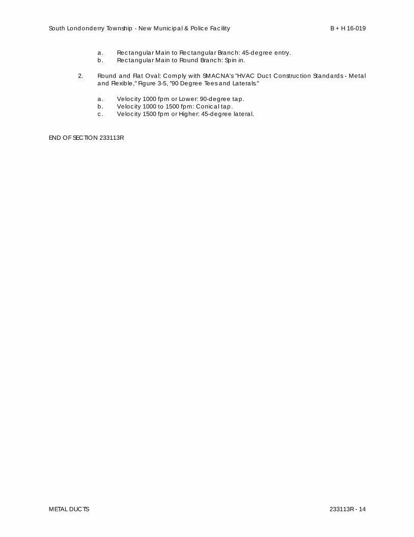
South Londonderry Township - New Municipal & Police Facility B + H 16-019
METAL DUCTS 233113R - 14
a. Rectangular Main to Rectangular Branch: 45-degree entry. b. Rectangular Main to Round Branch: Spin in.
2. Round and Flat Oval: Comply with SMACNA's "HVAC Duct Construction Standards - Metal and Flexible," Figure 3-5, "90 Degree Tees and Laterals."
a. Velocity 1000 fpm or Lower: 90-degree tap. b. Velocity 1000 to 1500 fpm: Conical tap. c. Velocity 1500 fpm or Higher: 45-degree lateral.
END OF SECTION 233113R
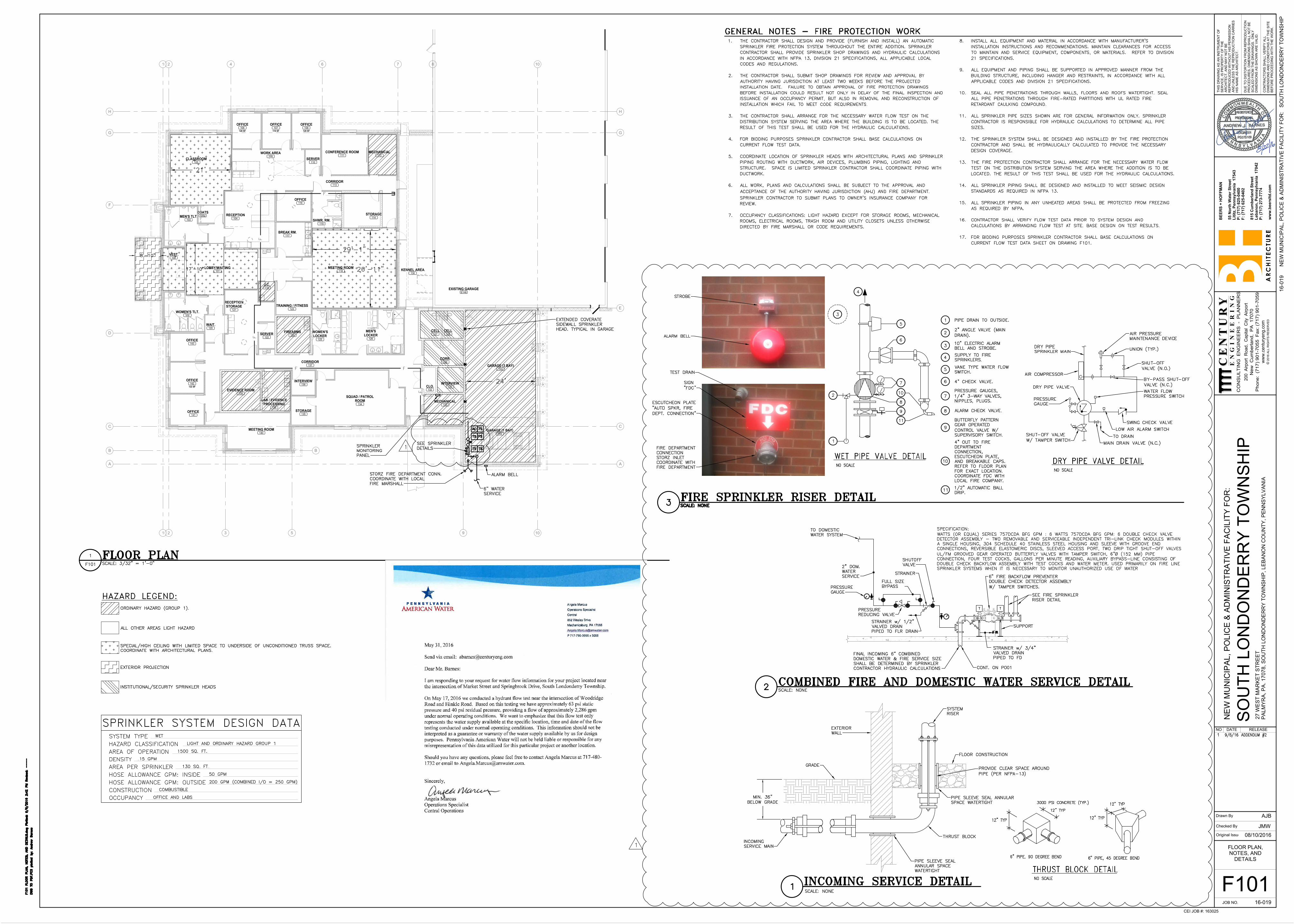
144
GARAGE (3 BAY)
129
CORR.
128
CELL
127
CELL
126
MEN'S
LOCKER
125
WOMEN'S
LOCKER
133
MECHANICAL
134
SQUAD / PATROL
ROOM
140
MEETING ROOM
136
INTERVIEW
143
OFFICE
122 SF
142
OFFICE
141
OFFICE
102
WOMEN'S TLT.
122
SERVER
103
MEN'S TLT.
131
INTERVIEW
117
BREAK RM.
138
LAB / EVIDENCE
PROCESSING
139
EVIDENCE ROOM
124
FIREARMS
123
TRAINING / FITNESS
119 SF
107
OFFICE
120 SF
106
OFFICE
120 SF
108
OFFICE
111
CONFERENCE ROOM
115
SHWR. RM.
118
MEETING ROOM
101
LOBBY/WAITING
145
GARAGE (1 BAY)
135
STORAGE
132
CLO.
105
CLASSROOM
116
OFFICE
112
MECHANICAL
104
RECEPTION
114
STORAGE
110
SERVER
119
J.C.
100
VEST.
109
WORK AREA
113
CORRIDOR
121
RECEPTION
STORAGE
120
WAIT.
137
CORRIDOR
105a
COATS
E146
EXISTING GARAGE
130
KENNEL AREA
RE
F.
764
2
2
1
1
10
10
HH
GG
F
D
CC
BB
AA
3 5 9
E
8
Original Issue Date:
Drawn By
Checked By
JOB NO.
TH
IS
D
RA
WIN
G A
S A
N IN
ST
RU
ME
NT
O
F
SE
RV
IC
E, IS
P
RO
PE
RT
Y O
F T
HE
AR
CH
IT
EC
T, A
ND
M
AY
N
OT
B
E
RE
PR
OD
UC
ED
W
IT
HO
UT
H
IS
P
ER
MIS
SIO
N
AN
D U
NLE
SS
T
HE
R
EP
RO
DU
CT
IO
N C
AR
RIE
S
HIS
N
AM
E A
S A
RC
HIT
EC
T.
DU
E T
O D
IS
TO
RT
IO
N F
RO
M R
EP
RO
DU
CT
IO
N
PR
OC
ED
UR
ES
, D
IM
EN
SIO
NS
S
HA
LL
N
OT
B
E
SC
AL
ED
F
RO
M T
HE
D
RA
WIN
GS
. O
NL
Y
DIM
EN
SIO
NS
A
S S
HO
WN
A
RE
V
ALID
.
CO
NT
RA
CT
OR
S S
HA
LL V
ER
IF
Y A
LL
DIM
EN
SIO
NS
A
ND
C
ON
DIT
IO
NS
A
T T
HE
S
IT
E
BE
FO
RE
P
RO
CE
ED
IN
G W
IT
H T
HE
W
OR
K.
55 N
orth
W
ater S
treet
Lititz, P
en
nsylvan
ia 17543
P: (717) 625-0400
F: (717) 625-0402
815 C
um
berlan
d S
treet
Leb
an
on
, P
en
nsylvan
ia 17042
P: (717) 273-7774
ww
w.b
eersltd
.co
m
PR
OG
RE
SS
S
ET
- N
OT
F
OR
C
ON
ST
RU
CT
IO
N
BE
ER
S +
H
OF
FM
AN
16-019
NE
W M
UN
IC
IP
AL
, P
OL
IC
E &
A
DM
IN
IS
TR
AT
IV
E F
AC
IL
IT
Y F
OR
:
SO
UT
H LO
ND
ON
DE
RR
Y T
OW
NS
HIP
27
W
ES
T M
AR
KE
T S
TR
EE
T
PA
LM
YR
A, P
A. 1
70
78
, S
OU
TH
L
ON
DO
ND
ER
RY
T
OW
NS
HIP
, L
EB
AN
ON
C
OU
NT
Y, P
EN
NS
YL
VA
NIA
16
-0
19
N
EW
M
UN
IC
IP
AL
, P
OL
IC
E &
A
DM
IN
IS
TR
AT
IV
E F
AC
IL
IT
Y F
OR
: S
OU
TH
L
ON
DO
ND
ER
RY
T
OW
NS
HIP
NO DATE RELEASE
CE
NT
UR
YC
EN
TU
RY
EN
GI
NE
ER
IN
G
Phone: (717) 901-7055 F
ax: (717) 901-7059
New
C
um
berland, P
A 17070
20
0 A
irp
ort R
oa
d, C
ap
ita
l C
ity A
irp
ort
CO
NS
ULT
IN
G E
NG
IN
EE
RS
- P
LA
NN
ER
S
ww
w.centuryeng.com
© 2
01
6 A
LL
R
IG
HT
S R
ES
ER
VE
D
CEI JOB #: 163025
F101
JMW
AJB
08/10/2016
FLOOR PLAN,
NOTES, AND
DETAILS
AutoCAD SHX Text
STORZ FIRE DEPARTMENT CONN. COORDINATE WITH LOCAL FIRE MARSHALL
AutoCAD SHX Text
SEE SPRINKLER DETAILS
AutoCAD SHX Text
6" WATER SERVICE
AutoCAD SHX Text
ALARM BELL
AutoCAD SHX Text
TS
AutoCAD SHX Text
FS
AutoCAD SHX Text
SPRINKLER MONITORING PANEL
AutoCAD SHX Text
EXTENDED COVERATE SIDEWALL SPRINKLER HEAD. TYPICAL IN GARAGE
AutoCAD SHX Text
TS
AutoCAD SHX Text
TS
AutoCAD SHX Text
AC
AutoCAD SHX Text
TS
AutoCAD SHX Text
F101 FLOOR PLAN, NOTES, AND DETAILS.dwg Plotted: 9/6/2016 2:42 PM Revised: ----
AutoCAD SHX Text
DWG TO PDF.PC3 plotted by: Andrew Barnes
AutoCAD SHX Text
1.THE CONTRACTOR SHALL DESIGN AND PROVIDE (FURNISH AND INSTALL) AN AUTOMATIC THE CONTRACTOR SHALL DESIGN AND PROVIDE (FURNISH AND INSTALL) AN AUTOMATIC SPRINKLER FIRE PROTECTION SYSTEM THROUGHOUT THE ENTIRE ADDITION. SPRINKLER CONTRACTOR SHALL PROVIDE SPRINKLER SHOP DRAWINGS AND HYDRAULIC CALCULATIONS IN ACCORDANCE WITH NFPA 13, DIVISION 21 SPECIFICATIONS, ALL APPLICABLE LOCAL CODES AND REGULATIONS. 2.THE CONTRACTOR SHALL SUBMIT SHOP DRAWINGS FOR REVIEW AND APPROVAL BY THE CONTRACTOR SHALL SUBMIT SHOP DRAWINGS FOR REVIEW AND APPROVAL BY AUTHORITY HAVING JURISDICTION AT LEAST TWO WEEKS BEFORE THE PROJECTED INSTALLATION DATE. FAILURE TO OBTAIN APPROVAL OF FIRE PROTECTION DRAWINGS BEFORE INSTALLATION COULD RESULT NOT ONLY IN DELAY OF THE FINAL INSPECTION AND ISSUANCE OF AN OCCUPANCY PERMIT, BUT ALSO IN REMOVAL AND RECONSTRUCTION OF INSTALLATION WHICH FAIL TO MEET CODE REQUIREMENTS. 3.THE CONTRACTOR SHALL ARRANGE FOR THE NECESSARY WATER FLOW TEST ON THE THE CONTRACTOR SHALL ARRANGE FOR THE NECESSARY WATER FLOW TEST ON THE DISTRIBUTION SYSTEM SERVING THE AREA WHERE THE BUILDING IS TO BE LOCATED. THE RESULT OF THIS TEST SHALL BE USED FOR THE HYDRAULIC CALCULATIONS. 4.FOR BIDDING PURPOSES SPRINKLER CONTRACTOR SHALL BASE CALCULATIONS ON FOR BIDDING PURPOSES SPRINKLER CONTRACTOR SHALL BASE CALCULATIONS ON CURRENT FLOW TEST DATA. 5.COORDINATE LOCATION OF SPRINKLER HEADS WITH ARCHITECTURAL PLANS AND SPRINKLER COORDINATE LOCATION OF SPRINKLER HEADS WITH ARCHITECTURAL PLANS AND SPRINKLER PIPING ROUTING WITH DUCTWORK, AIR DEVICES, PLUMBING PIPING, LIGHTING AND STRUCTURE. SPACE IS LIMITED SPRINKLER CONTRACTOR SHALL COORDINATE PIPING WITH DUCTWORK. 6.ALL WORK, PLANS AND CALCULATIONS SHALL BE SUBJECT TO THE APPROVAL AND ALL WORK, PLANS AND CALCULATIONS SHALL BE SUBJECT TO THE APPROVAL AND ACCEPTANCE OF THE AUTHORITY HAVING JURISDICTION (AHJ) AND FIRE DEPARTMENT. THE AUTHORITY HAVING JURISDICTION (AHJ) AND FIRE DEPARTMENT. . SPRINKLER CONTRACTOR TO SUBMIT PLANS TO OWNER'S INSURANCE COMPANY FOR REVIEW. 7.OCCUPANCY CLASSIFICATIONS: LIGHT HAZARD EXCEPT FOR STORAGE ROOMS, MECHANICAL OCCUPANCY CLASSIFICATIONS: LIGHT HAZARD EXCEPT FOR STORAGE ROOMS, MECHANICAL ROOMS, ELECTRICAL ROOMS, TRASH ROOM AND UTILITY CLOSETS UNLESS OTHERWISE DIRECTED BY FIRE MARSHALL OR CODE REQUIREMENTS. 8.INSTALL ALL EQUIPMENT AND MATERIAL IN ACCORDANCE WITH MANUFACTURER'S INSTALL ALL EQUIPMENT AND MATERIAL IN ACCORDANCE WITH MANUFACTURER'S INSTALLATION INSTRUCTIONS AND RECOMMENDATIONS. MAINTAIN CLEARANCES FOR ACCESS TO MAINTAIN AND SERVICE EQUIPMENT, COMPONENTS, OR MATERIALS. REFER TO DIVISION 21 SPECIFICATIONS. 9.ALL EQUIPMENT AND PIPING SHALL BE SUPPORTED IN APPROVED MANNER FROM THE ALL EQUIPMENT AND PIPING SHALL BE SUPPORTED IN APPROVED MANNER FROM THE BUILDING STRUCTURE, INCLUDING HANGER AND RESTRAINTS, IN ACCORDANCE WITH ALL APPLICABLE CODES AND DIVISION 21 SPECIFICATIONS. 10.SEAL ALL PIPE PENETRATIONS THROUGH WALLS, FLOORS AND ROOFS WATERTIGHT. SEAL SEAL ALL PIPE PENETRATIONS THROUGH WALLS, FLOORS AND ROOFS WATERTIGHT. SEAL ALL PIPE PENETRATIONS THROUGH FIRE-RATED PARTITIONS WITH UL RATED FIRE RETARDANT CAULKING COMPOUND. 11.ALL SPRINKLER PIPE SIZES SHOWN ARE FOR GENERAL INFORMATION ONLY. SPRINKLER ALL SPRINKLER PIPE SIZES SHOWN ARE FOR GENERAL INFORMATION ONLY. SPRINKLER CONTRACTOR IS RESPONSIBLE FOR HYDRAULIC CALCULATIONS TO DETERMINE ALL PIPE SIZES. 12.THE SPRINKLER SYSTEM SHALL BE DESIGNED AND INSTALLED BY THE FIRE PROTECTION THE SPRINKLER SYSTEM SHALL BE DESIGNED AND INSTALLED BY THE FIRE PROTECTION CONTRACTOR AND SHALL BE HYDRAULICALLY CALCULATED TO PROVIDE THE NECESSARY DESIGN COVERAGE. 13.THE FIRE PROTECTION CONTRACTOR SHALL ARRANGE FOR THE NECESSARY WATER FLOW THE FIRE PROTECTION CONTRACTOR SHALL ARRANGE FOR THE NECESSARY WATER FLOW TEST ON THE DISTRIBUTION SYSTEM SERVING THE AREA WHERE THE ADDITION IS TO BE LOCATED. THE RESULT OF THIS TEST SHALL BE USED FOR THE HYDRAULIC CALCULATIONS. 14.ALL SPRINKLER PIPING SHALL BE DESIGNED AND INSTALLED TO MEET SEISMIC DESIGN ALL SPRINKLER PIPING SHALL BE DESIGNED AND INSTALLED TO MEET SEISMIC DESIGN STANDARDS AS REQUIRED IN NFPA 13. 15.ALL SPRINKLER PIPING IN ANY UNHEATED AREAS SHALL BE PROTECTED FROM FREEZING ALL SPRINKLER PIPING IN ANY UNHEATED AREAS SHALL BE PROTECTED FROM FREEZING AS REQUIRED BY NFPA. 16.CONTRACTOR SHALL VERIFY FLOW TEST DATA PRIOR TO SYSTEM DESIGN AND CONTRACTOR SHALL VERIFY FLOW TEST DATA PRIOR TO SYSTEM DESIGN AND CALCULATIONS BY ARRANGING FLOW TEST AT SITE. BASE DESIGN ON TEST RESULTS. 17.FOR BIDDING PURPOSES SPRINKLER CONTRACTOR SHALL BASE CALCULATIONS ON FOR BIDDING PURPOSES SPRINKLER CONTRACTOR SHALL BASE CALCULATIONS ON CURRENT FLOW TEST DATA SHEET ON DRAWING F101.
AutoCAD SHX Text
GRADE
AutoCAD SHX Text
EXTERIOR WALL
AutoCAD SHX Text
SYSTEM RISER
AutoCAD SHX Text
PIPE SLEEVE SEAL ANNULAR SPACE WATERTIGHT
AutoCAD SHX Text
THRUST BLOCK
AutoCAD SHX Text
PIPE SLEEVE SEAL ANNULAR SPACE WATERTIGHT
AutoCAD SHX Text
%%UINCOMING SERVICE DETAIL
AutoCAD SHX Text
SCALE: NONE
AutoCAD SHX Text
FLOOR CONSTRUCTION
AutoCAD SHX Text
INCOMING SERVICE MAIN
AutoCAD SHX Text
PROVIDE CLEAR SPACE AROUND PIPE (PER NFPA-13)
AutoCAD SHX Text
1
AutoCAD SHX Text
PIPE DRAIN TO OUTSIDE.
AutoCAD SHX Text
2" ANGLE VALVE (MAIN DRAIN).
AutoCAD SHX Text
10" ELECTRIC ALARM BELL AND STROBE.
AutoCAD SHX Text
SUPPLY TO FIRE SPRINKLERS.
AutoCAD SHX Text
VANE TYPE WATER FLOW SWITCH.
AutoCAD SHX Text
4" CHECK VALVE.
AutoCAD SHX Text
PRESSURE GAUGES, 1/4" 3-WAY VALVES, NIPPLES, PLUGS.
AutoCAD SHX Text
ALARM CHECK VALVE.
AutoCAD SHX Text
BUTTERFLY PATTERN GEAR OPERATED CONTROL VALVE W/ SUPERVISORY SWITCH.
AutoCAD SHX Text
4" OUT TO FIRE DEPARTMENT CONNECTION, ESCUTCHEON PLATE, AND BREAKABLE CAPS. REFER TO FLOOR PLAN FOR EXACT LOCATION. COORDINATE FDC WITH LOCAL FIRE COMPANY.
AutoCAD SHX Text
1/2" AUTOMATIC BALL DRIP.
AutoCAD SHX Text
1
AutoCAD SHX Text
2
AutoCAD SHX Text
3
AutoCAD SHX Text
4
AutoCAD SHX Text
5
AutoCAD SHX Text
6
AutoCAD SHX Text
7
AutoCAD SHX Text
8
AutoCAD SHX Text
9
AutoCAD SHX Text
10
AutoCAD SHX Text
11
AutoCAD SHX Text
2
AutoCAD SHX Text
3
AutoCAD SHX Text
4
AutoCAD SHX Text
5
AutoCAD SHX Text
6
AutoCAD SHX Text
7
AutoCAD SHX Text
10
AutoCAD SHX Text
8
AutoCAD SHX Text
9
AutoCAD SHX Text
11
AutoCAD SHX Text
FIRE DEPARTMENT CONNECTION STORZ INLET COORDINATE WITH FIRE DEPARTMENT
AutoCAD SHX Text
ESCUTCHEON PLATE "AUTO SPKR, FIRE DEPT. CONNECTION"
AutoCAD SHX Text
SIGN "FDC"
AutoCAD SHX Text
ALARM BELL
AutoCAD SHX Text
STROBE
AutoCAD SHX Text
GENERAL NOTES - FIRE PROTECTION WORK
AutoCAD SHX Text
HAZARD LEGEND:
AutoCAD SHX Text
ORDINARY HAZARD (GROUP 1).
AutoCAD SHX Text
ALL OTHER AREAS LIGHT HAZARD
AutoCAD SHX Text
SPECIAL/HIGH CEILING WITH LIMITED SPACE TO UNDERSIDE OF UNCONDITIONED TRUSS SPACE. COORDINATE WITH ARCHITECTURAL PLANS.
AutoCAD SHX Text
EXTERIOR PROJECTION
AutoCAD SHX Text
INSTITUTIONAL/SECURITY SPRINKLER HEADS
AutoCAD SHX Text
F101
AutoCAD SHX Text
SCALE: 3/32" = 1'-0"
AutoCAD SHX Text
%%UFLOOR PLAN
AutoCAD SHX Text
1
AutoCAD SHX Text
%%UCOMBINED FIRE AND DOMESTIC WATER SERVICE DETAIL
AutoCAD SHX Text
SCALE: NONE
AutoCAD SHX Text
FINAL INCOMING 6" COMBINED DOMESTIC WATER & FIRE SERVICE SIZE SHALL BE DETERMINED BY SPRINKLER CONTRACTOR HYDRAULIC CALCULATIONS
AutoCAD SHX Text
PRESSURE REDUCING VALVE
AutoCAD SHX Text
TO DOMESTIC WATER SYSTEM
AutoCAD SHX Text
STRAINER
AutoCAD SHX Text
SHUTOFF VALVE
AutoCAD SHX Text
CONT. ON P001
AutoCAD SHX Text
SYSTEM TYPE
AutoCAD SHX Text
HAZARD CLASSIFICATION
AutoCAD SHX Text
AREA OF OPERATION
AutoCAD SHX Text
DENSITY
AutoCAD SHX Text
AREA PER SPRINKLER
AutoCAD SHX Text
HOSE ALLOWANCE GPM: INSIDE
AutoCAD SHX Text
HOSE ALLOWANCE GPM: OUTSIDE
AutoCAD SHX Text
CONSTRUCTION
AutoCAD SHX Text
OCCUPANCY
AutoCAD SHX Text
SPRINKLER SYSTEM DESIGN DATA
AutoCAD SHX Text
WET
AutoCAD SHX Text
LIGHT AND ORDINARY HAZARD GROUP 1
AutoCAD SHX Text
1500 SQ. FT.
AutoCAD SHX Text
.15 GPM
AutoCAD SHX Text
130 SQ. FT.
AutoCAD SHX Text
50 GPM
AutoCAD SHX Text
200 GPM (COMBINED I/O = 250 GPM)
AutoCAD SHX Text
COMBUSTIBLE
AutoCAD SHX Text
OFFICE AND LABS
AutoCAD SHX Text
SCALE: NONE
AutoCAD SHX Text
FIRE SPRINKLER RISER DETAIL
AutoCAD SHX Text
3
AutoCAD SHX Text
PRESSURE GAUGE
AutoCAD SHX Text
2
AutoCAD SHX Text
1
AutoCAD SHX Text
TEST DRAIN
AutoCAD SHX Text
3000 PSI CONCRETE (TYP.)
AutoCAD SHX Text
%%uTHRUST BLOCK DETAIL
AutoCAD SHX Text
NO SCALE
AutoCAD SHX Text
6" PIPE, 90 DEGREE BEND
AutoCAD SHX Text
12" TYP
AutoCAD SHX Text
12" TYP
AutoCAD SHX Text
6" PIPE, 45 DEGREE BEND
AutoCAD SHX Text
12" TYP
AutoCAD SHX Text
12" TYP
AutoCAD SHX Text
6" FIRE BACKFLOW PREVENTER DOUBLE CHECK DETECTOR ASSEMBLY W/ TAMPER SWITCHES.
AutoCAD SHX Text
30" MAX.
AutoCAD SHX Text
12" MIN.
AutoCAD SHX Text
SUPPORT
AutoCAD SHX Text
T
AutoCAD SHX Text
T
AutoCAD SHX Text
SEE FIRE SPRINKLER RISER DETAIL
AutoCAD SHX Text
SPECIFICATION: WATTS (OR EQUAL) SERIES 757DCDA BFG GPM : 6 WATTS 757DCDA BFG GPM: 6 DOUBLE CHECK VALVE DETECTOR ASSEMBLY - TWO REMOVABLE AND SERVICEABLE INDEPENDENT TRI-LINK CHECK MODULES WITHIN A SINGLE HOUSING, 304 SCHEDULE 40 STAINLESS STEEL HOUSING AND SLEEVE WITH GROOVE END CONNECTIONS, REVERSIBLE ELASTOMERIC DISCS, SLEEVED ACCESS PORT, TWO DRIP TIGHT SHUT-OFF VALVES UL/FM GROOVED GEAR OPERATED BUTTERFLY VALVES WITH TAMPER SWITCH, 6"Ø (152 MM) PIPE CONNECTION, FOUR TEST COCKS, GALLONS PER MINUTE READING, AUXILIARY BYPASS-LINE CONSISTING OF DOUBLE CHECK BACKFLOW ASSEMBLY WITH TEST COCKS AND WATER METER. USED PRIMARILY ON FIRE LINE SPRINKLER SYSTEMS WHEN IT IS NECESSARY TO MONITOR UNAUTHORIZED USE OF WATER
AutoCAD SHX Text
TO DRAIN
AutoCAD SHX Text
SHUT-OFF VALVE W/ TAMPER SWITCH
AutoCAD SHX Text
PRESSURE GAUGE
AutoCAD SHX Text
DRY PIPE VALVE
AutoCAD SHX Text
AIR COMPRESSOR
AutoCAD SHX Text
DRY PIPE SPRINKLER MAIN
AutoCAD SHX Text
MAIN DRAIN VALVE (N.C.)
AutoCAD SHX Text
SWING CHECK VALVE
AutoCAD SHX Text
LOW AIR ALARM SWITCH
AutoCAD SHX Text
WATER FLOW PRESSURE SWITCH
AutoCAD SHX Text
BY-PASS SHUT-OFF VALVE (N.C.)
AutoCAD SHX Text
SHUT-OFF VALVE (N.O.)
AutoCAD SHX Text
UNION (TYP.)
AutoCAD SHX Text
AIR PRESSURE MAINTENANCE DEVICE
AutoCAD SHX Text
%%UDRY PIPE VALVE DETAIL
AutoCAD SHX Text
NO SCALE
AutoCAD SHX Text
%%UWET PIPE VALVE DETAIL
AutoCAD SHX Text
NO SCALE
AutoCAD SHX Text
1
AutoCAD SHX Text
1
AutoCAD SHX Text
ADDENDUM #2
AutoCAD SHX Text
9/6/16
AutoCAD SHX Text
1
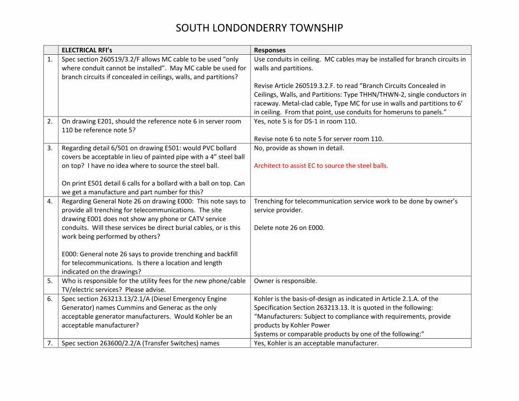
SOUTH LONDONDERRY TOWNSHIP
ELECTRICAL RFI’s Responses
1. Spec section 260519/3.2/F allows MC cable to be used “only where conduit cannot be installed”. May MC cable be used for branch circuits if concealed in ceilings, walls, and partitions?
Use conduits in ceiling. MC cables may be installed for branch circuits in walls and partitions. Revise Article 260519.3.2.F. to read “Branch Circuits Concealed in Ceilings, Walls, and Partitions: Type THHN/THWN-2, single conductors in raceway. Metal-clad cable, Type MC for use in walls and partitions to 6’ in ceiling. From that point, use conduits for homeruns to panels.”
2. On drawing E201, should the reference note 6 in server room 110 be reference note 5?
Yes, note 5 is for DS-1 in room 110. Revise note 6 to note 5 for server room 110.
3. Regarding detail 6/501 on drawing E501: would PVC bollard covers be acceptable in lieu of painted pipe with a 4” steel ball on top? I have no idea where to source the steel ball. On print E501 detail 6 calls for a bollard with a ball on top. Can we get a manufacture and part number for this?
No, provide as shown in detail. Architect to assist EC to source the steel balls.
4. Regarding General Note 26 on drawing E000: This note says to provide all trenching for telecommunications. The site drawing E001 does not show any phone or CATV service conduits. Will these services be direct burial cables, or is this work being performed by others? E000: General note 26 says to provide trenching and backfill for telecommunications. Is there a location and length indicated on the drawings?
Trenching for telecommunication service work to be done by owner’s service provider. Delete note 26 on E000.
5. Who is responsible for the utility fees for the new phone/cable TV/electric services? Please advise.
Owner is responsible.
6. Spec section 263213.13/2.1/A (Diesel Emergency Engine Generator) names Cummins and Generac as the only acceptable generator manufacturers. Would Kohler be an acceptable manufacturer?
Kohler is the basis-of-design as indicated in Article 2.1.A. of the Specification Section 263213.13. It is quoted in the following: “Manufacturers: Subject to compliance with requirements, provide products by Kohler Power Systems or comparable products by one of the following:”
7. Spec section 263600/2.2/A (Transfer Switches) names Yes, Kohler is an acceptable manufacturer.
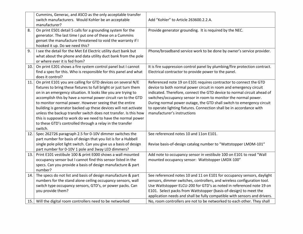
Cummins, Generac, and ASCO as the only acceptable transfer switch manufacturers. Would Kohler be an acceptable manufacturer?
Add “Kohler” to Article 263600.2.2.A.
8. On print E501 detail 5 calls for a grounding system for the generator. The last time I put one of these on a Cummins genset the manufacture threatened to void the warranty if I hooked it up. Do we need this?
Provide generator grounding. It is required by the NEC.
9. I see the detail for the Met Ed Electric utility duct bank but what about the phone and data utility duct bank from the pole or where ever it is fed from?
Phone/broadband service work to be done by owner’s service provider.
10. On print E201 shows a fire system control panel but I cannot find a spec for this. Who is responsible for this panel and what does it control?
It is fire suppression control panel by plumbing/fire protection contract. Electrical contractor to provide power to the panel.
11. On print E101 you are calling for GTD devices on several N/E fixtures to bring these fixtures to full bright or just turn them on in an emergency situation. It looks like you are trying to accomplish this by have a normal power circuit ran to the GTD to monitor normal power. However seeing that the entire building is generator backed up these devices will not activate unless the backup transfer switch does not transfer. Is this how this is supposed to work do we need to have the normal power to these GTD’s controlled through a relay in the transfer switch.
Referenced note 19 on E101 requires contractor to connect the GTD device to both normal power circuit in room and emergency circuit indicated. Therefore, connect the GTD device to normal circuit ahead of switches/occupancy sensor in room to monitor the normal power. During normal power outage, the GTD shall switch to emergency circuit to operate lighting fixtures. Connection shall be in accordance with manufacturer’s instructions
12. Spec 262726 paragraph 2.5 for 0-10V dimmer switches the part number for basis of design that you list is for a Hubbell single pole pilot light switch. Can you give us a basis of design part number for 0-10V 1 pole and 3way LED dimmers?
See referenced notes 10 and 11on E101. Revise basis-of-design catalog number to “Wattstopper LMDM-101“
13. Print E101 vestibule 100 & print E000 shows a wall mounted occupancy sensor but I cannot find this sensor listed in the specs. Can you provide a basis of design manufacture & part number?
Add note to occupancy sensor in vestibule 100 on E101 to read “Wall mounted occupancy sensor: Wattstopper LMDX-100”
14. The specs do not list and basis of design manufacture & part numbers for the stand alone ceiling occupancy sensors, wall switch type occupancy sensors, GTD’s, or power packs. Can you provide them?
See referenced notes 10 and 11 on E101 for occupancy sensors, daylight sensors, dimmer switches, controllers, and wireless configuration tool. Use Wattstopper ELCU-200 for GTD’s as noted in referenced note 19 on E101. Select packs from Wattstopper (basis-of-design) to meet the application needs and shall be fully compatible with sensors and drivers.
15. Will the digital room controllers need to be networked No, room controllers are not to be networked to each other. They shall
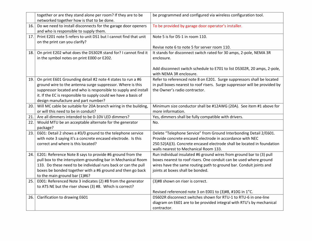
together or are they stand alone per room? If they are to be networked together how is that to be done.
be programmed and configured via wireless configuration tool.
16. Do we need to install disconnects for the garage door openers and who is responsible to supply them.
To be provided by garage door operator’s installer.
17. Print E201 note 5 refers to unit DS1 but I cannot find that unit on the print can you clarify?
Note 5 is for DS-1 in room 110. Revise note 6 to note 5 for server room 110.
18. On print E202 what does the DS302R stand for? I cannot find it in the symbol notes on print E000 or E202.
It stands for disconnect switch rated for 30 amps, 2-pole, NEMA 3R enclosure. Add disconnect switch schedule to E701 to list DS302R, 20 amps, 2-pole, with NEMA 3R enclosure.
19. On print E601 Grounding detail #2 note 4 states to run a #6 ground wire to the antenna surge suppressor. Where is this suppressor located and who is responsible to supply and install it. If the EC is responsible to supply could we have a basis of design manufacture and part number?
Refer to referenced note 8 on E201. Surge suppressors shall be located in pull boxes nearest to roof risers. Surge suppressor will be provided by the Owner’s radio contractor.
20. Will MC cable be suitable for 20A branch wiring in the building, or will this need to be in conduit?
Minimum size conductor shall be #12AWG (20A). See item #1 above for more information.
21. Are all dimmers intended to be 0-10V LED dimmers? Yes, dimmers shall be fully compatible with drivers.
22. Would MTU be an acceptable alternate for the generator package?
No.
23. E601: Detail 2 shows a #3/0 ground to the telephone service with note 3 saying it's a concrete encased electrode. Is this correct and where is this located?
Delete “Telephone Service” from Ground Interbonding Detail 2/E601. Provide concrete encased electrode in accordance with NEC 250.52(A)(3). Concrete encased electrode shall be located in foundation walls nearest to Mechanical Room 133.
24. E201: Reference Note 8 says to provide #6 ground from the pull box to the intersystem grounding bar in Mechanical Room 133. Do these need to be individual runs back or can the pull boxes be bonded together with a #6 ground and then go back to the main ground bar (1)#6?
Run individual insulated #6 ground wires from ground bar to (3) pull boxes nearest to roof risers. One conduit can be used where ground wires have the same routing path to ground bar. Conduit joints and joints at boxes shall be bonded.
25. E001: Referenced Note 3 indicates (2) #8 from the generator to ATS NE but the riser shows (3) #8. Which is correct?
(3)#8 shown on riser is correct. Revised referenced note 3 on E001 to (3)#8, #10G in 1”C.
26. Clarification to drawing E601 DS602R disconnect switches shown for RTU-1 to RTU-6 in one-line diagram on E601 are to be provided integral with RTU’s by mechanical contractor.
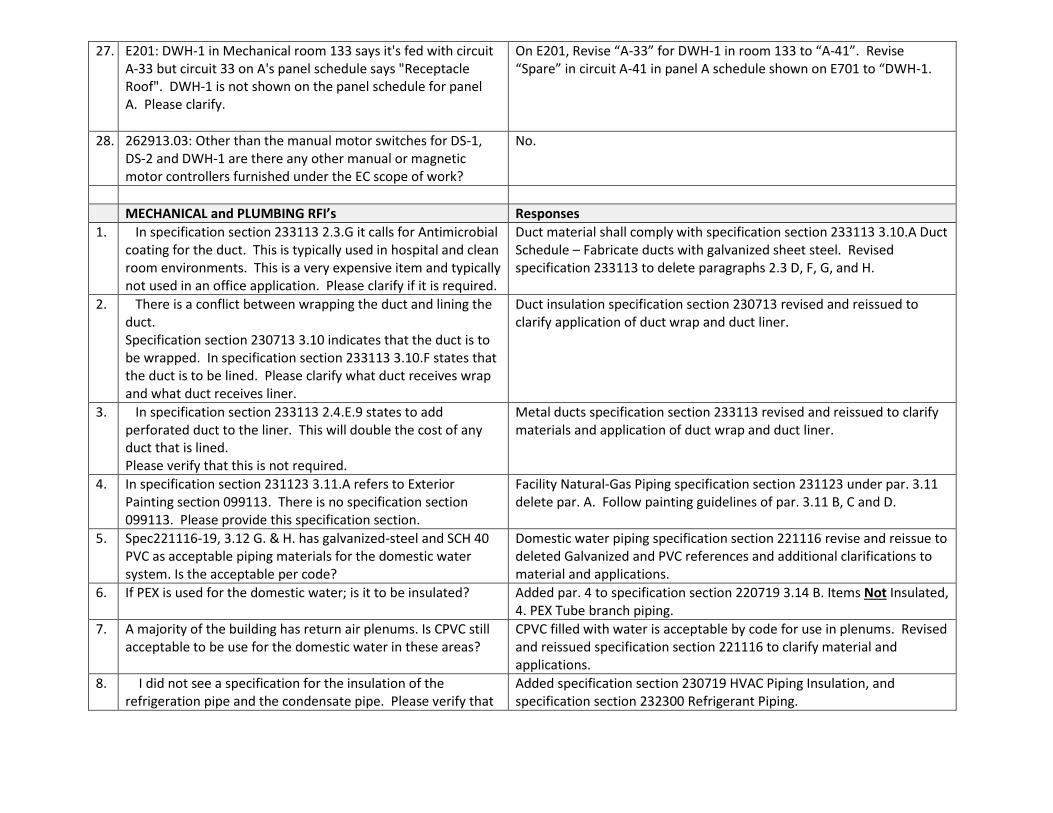
27. E201: DWH-1 in Mechanical room 133 says it's fed with circuit A-33 but circuit 33 on A's panel schedule says "Receptacle Roof". DWH-1 is not shown on the panel schedule for panel A. Please clarify.
On E201, Revise “A-33” for DWH-1 in room 133 to “A-41”. Revise “Spare” in circuit A-41 in panel A schedule shown on E701 to “DWH-1.
28. 262913.03: Other than the manual motor switches for DS-1, DS-2 and DWH-1 are there any other manual or magnetic motor controllers furnished under the EC scope of work?
No.
MECHANICAL and PLUMBING RFI’s Responses
1. In specification section 233113 2.3.G it calls for Antimicrobial coating for the duct. This is typically used in hospital and clean room environments. This is a very expensive item and typically not used in an office application. Please clarify if it is required.
Duct material shall comply with specification section 233113 3.10.A Duct Schedule – Fabricate ducts with galvanized sheet steel. Revised specification 233113 to delete paragraphs 2.3 D, F, G, and H.
2. There is a conflict between wrapping the duct and lining the duct. Specification section 230713 3.10 indicates that the duct is to be wrapped. In specification section 233113 3.10.F states that the duct is to be lined. Please clarify what duct receives wrap and what duct receives liner.
Duct insulation specification section 230713 revised and reissued to clarify application of duct wrap and duct liner.
3. In specification section 233113 2.4.E.9 states to add perforated duct to the liner. This will double the cost of any duct that is lined. Please verify that this is not required.
Metal ducts specification section 233113 revised and reissued to clarify materials and application of duct wrap and duct liner.
4. In specification section 231123 3.11.A refers to Exterior Painting section 099113. There is no specification section 099113. Please provide this specification section.
Facility Natural-Gas Piping specification section 231123 under par. 3.11 delete par. A. Follow painting guidelines of par. 3.11 B, C and D.
5. Spec221116-19, 3.12 G. & H. has galvanized-steel and SCH 40 PVC as acceptable piping materials for the domestic water system. Is the acceptable per code?
Domestic water piping specification section 221116 revise and reissue to deleted Galvanized and PVC references and additional clarifications to material and applications.
6. If PEX is used for the domestic water; is it to be insulated? Added par. 4 to specification section 220719 3.14 B. Items Not Insulated, 4. PEX Tube branch piping.
7. A majority of the building has return air plenums. Is CPVC still acceptable to be use for the domestic water in these areas?
CPVC filled with water is acceptable by code for use in plenums. Revised and reissued specification section 221116 to clarify material and applications.
8. I did not see a specification for the insulation of the refrigeration pipe and the condensate pipe. Please verify that
Added specification section 230719 HVAC Piping Insulation, and specification section 232300 Refrigerant Piping.
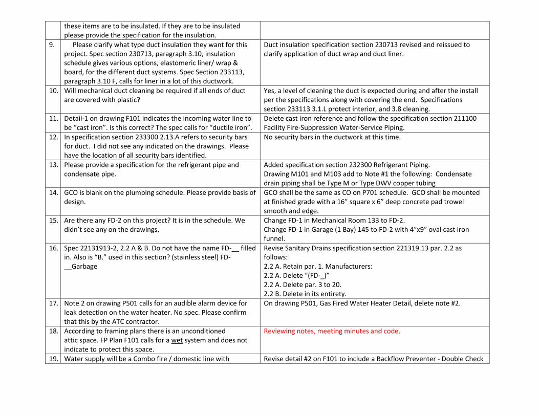
these items are to be insulated. If they are to be insulated please provide the specification for the insulation.
9. Please clarify what type duct insulation they want for this project. Spec section 230713, paragraph 3.10, insulation schedule gives various options, elastomeric liner/ wrap & board, for the different duct systems. Spec Section 233113, paragraph 3.10 F, calls for liner in a lot of this ductwork.
Duct insulation specification section 230713 revised and reissued to clarify application of duct wrap and duct liner.
10. Will mechanical duct cleaning be required if all ends of duct are covered with plastic?
Yes, a level of cleaning the duct is expected during and after the install per the specifications along with covering the end. Specifications section 233113 3.1.L protect interior, and 3.8 cleaning.
11. Detail-1 on drawing F101 indicates the incoming water line to be “cast iron”. Is this correct? The spec calls for “ductile iron”.
Delete cast iron reference and follow the specification section 211100 Facility Fire-Suppression Water-Service Piping.
12. In specification section 233300 2.13.A refers to security bars for duct. I did not see any indicated on the drawings. Please have the location of all security bars identified.
No security bars in the ductwork at this time.
13. Please provide a specification for the refrigerant pipe and condensate pipe.
Added specification section 232300 Refrigerant Piping. Drawing M101 and M103 add to Note #1 the following: Condensate drain piping shall be Type M or Type DWV copper tubing
14. GCO is blank on the plumbing schedule. Please provide basis of design.
GCO shall be the same as CO on P701 schedule. GCO shall be mounted at finished grade with a 16” square x 6” deep concrete pad trowel smooth and edge.
15. Are there any FD-2 on this project? It is in the schedule. We didn’t see any on the drawings.
Change FD-1 in Mechanical Room 133 to FD-2. Change FD-1 in Garage (1 Bay) 145 to FD-2 with 4”x9” oval cast iron funnel.
16. Spec 22131913-2, 2.2 A & B. Do not have the name FD-__ filled in. Also is “B.” used in this section? (stainless steel) FD-__Garbage
Revise Sanitary Drains specification section 221319.13 par. 2.2 as follows: 2.2 A. Retain par. 1. Manufacturers: 2.2 A. Delete “(FD-_)” 2.2 A. Delete par. 3 to 20. 2.2 B. Delete in its entirety.
17. Note 2 on drawing P501 calls for an audible alarm device for leak detection on the water heater. No spec. Please confirm that this by the ATC contractor.
On drawing P501, Gas Fired Water Heater Detail, delete note #2.
18. According to framing plans there is an unconditioned attic space. FP Plan F101 calls for a wet system and does not indicate to protect this space.
Reviewing notes, meeting minutes and code.
19. Water supply will be a Combo fire / domestic line with Revise detail #2 on F101 to include a Backflow Preventer - Double Check
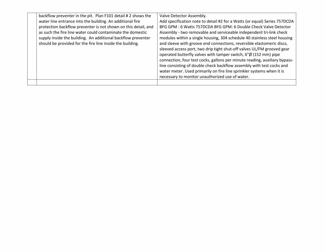
backflow preventer in the pit. Plan F101 detail # 2 shows the water line entrance into the building. An additional fire protection backflow preventer is not shown on this detail, and as such the fire line water could contaminate the domestic supply inside the building. An additional backflow preventer should be provided for the fire line inside the building.
Valve Detector Assembly. Add specification note to detail #2 for a Watts (or equal) Series 757DCDA BFG GPM : 6 Watts 757DCDA BFG GPM: 6 Double Check Valve Detector Assembly - two removable and serviceable independent tri-link check modules within a single housing, 304 schedule 40 stainless steel housing and sleeve with groove end connections, reversible elastomeric discs, sleeved access port, two drip tight shut-off valves UL/FM grooved gear operated butterfly valves with tamper switch, 6"Ø (152 mm) pipe connection, four test cocks, gallons per minute reading, auxiliary bypass-line consisting of double check backflow assembly with test cocks and water meter. Used primarily on fire line sprinkler systems when it is necessary to monitor unauthorized use of water.