BEE UNIT-1
90
BEE – UNIT-1 Unit – 1 (BEE) R -19 Regulations – I ECE II Semester DC Machines: Principle of operation of DC generator – emf equation – types of DC machines – torque equation of DC motor – applications – three point starter - losses and efficiency - Swinburne’s test - speed control methods – OCC of DC generator- Brake test on DC Shunt motor-numerical problems PRINCIPLE OF OPERATION OF DC GENERATOR 1. DC Generator is an electro mechanical energy conversion device used to convert mechanical energy to electrical energy. 2. It works as per Faradays laws of electromagnetic induction which states that 3. Fleming’s right hand rule is used to obtain the direction of the current in the coil of the DC Generator. Simple loop dc generator: The simple loop dc generator is assumed to have the following parts as shown in Fig (a) Two permanent magnets (North pole and South pole) as stator A single turn rectangular coil named as Armature (placed on the shaft) as rotor Two Slip rings rotating along with the armature coil Two static carbon brushes mounted on the slip rings External load or galvanometer The rectangular shaped armature coil is assumed to be rotated in anticlockwise with an angular velocity of ω rad/sec. The working operation of the simple loop generator is explained over one complete rotation of the coil for 360 0 and is shown in the below figure at different positions of the coil. I Law: “Whenever the conductor cuts the magnetic flux a dynamical emf is induced in the conductor” II Law: “The magnitude of the emf induced is directly proportional to the rate of change of flux linkages”
Transcript of BEE UNIT-1

BEE – UNIT-1
Unit – 1 (BEE) R -19 Regulations – I ECE II Semester
DC Machines: Principle of operation of DC generator – emf equation – types of DC
machines – torque equation of DC motor – applications – three point starter - losses and
efficiency - Swinburne’s test - speed control methods – OCC of DC generator- Brake test on
DC Shunt motor-numerical problems
PRINCIPLE OF OPERATION OF DC GENERATOR
1. DC Generator is an electro mechanical energy conversion device used to convert
mechanical energy to electrical energy.
2. It works as per Faradays laws of electromagnetic induction which states that
3. Fleming’s right hand rule is used to obtain the direction of the current in the coil of the
DC Generator.
Simple loop dc generator:
The simple loop dc generator is assumed to have
the following parts as shown in Fig (a)
Two permanent magnets (North pole and
South pole) as stator
A single turn rectangular coil named as
Armature (placed on the shaft) as rotor
Two Slip rings rotating along with the
armature coil
Two static carbon brushes mounted on the slip rings
External load or galvanometer
The rectangular shaped armature coil is assumed to be rotated in anticlockwise with an
angular velocity of ω rad/sec.
The working operation of the simple loop generator is explained over one complete rotation
of the coil for 3600 and is shown in the below figure at different positions of the coil.
I Law: “Whenever the conductor cuts the magnetic flux a dynamical emf is induced in the conductor”
II Law: “The magnitude of the emf induced is directly proportional to the rate of change of flux linkages”

BEE – UNIT-1
At 0 degrees Position (1):
1. This position is also known as the “Neutral Plane”;
2. In this position the loop is parallel to the magnetic lines
of flux
3. In this position there is maximum flux passing through
the coil.
4. No EMF is induced in the coil because of no “Change in flux through the loop”.
At 90 degrees Position (2):
1. After the loop has been rotated 90 degrees
clockwise through the magnetic field the flux
linkage through it now becomes zero.
2. But the rate of change of flux through it was
maximum,
3. This results in an induced EMF which climbs from zero to its peak value.
At 180 degrees Position (3):
1. Once again the coil is rotated 90 degrees clockwise
resulting in the completion of a 180 degrees cycle.
2. Here the loop is perpendicular to the magnetic lines
of force
3. This means that there is maximum flux density through it resulting the EMF to falls
back to zero.
At 270 degrees Position (4):
1. At 270 degrees the flux linkage through the loop is
once again zero,
2. but the rate of change of flux is maximum.
3. In this position, the EMF induced goes up to its
peak value, but this time it’s in the reverse direction.
At 360 degrees Position(5):
1. The loop is rotated through another 90 degrees such
that it has completed a rotation of 360 degrees.
2. The flux linkage through it is maximum and the
voltage decreases back to zero.

BEE – UNIT-1
Hence, it is observed that the nature of the emf induced in the armature coil is
alternating quantity (i.e, positive voltage during first half cycle and negative voltage
during second half cycle)
Thus, to convert the induced alternating ac to dc nature the Commutator (or) split
rings are used in the place of the slip rings of a simple loop generator.
ACTION OF COMMUTATOR:
The Commutator is a mechanical rectifier used to convert
AC to DC
Here, the split rings or Commutator segments (s1 and s2) are
placed instead of slip rings
The split rings or commutator are made out of conducting
cylinder, which is cut into two halves or segments insulated from each other by a thin
sheet of mica.
Brushes B1 and B2 are mounted on two Commutator segments having + and - polarities
At θ = 900position :
Conductor AB is under South Pole and Conductor CD are under North Pole, with coil
rotating in clock wise direction.
Using Flemings right hand rule, the current in the conductor AB is from B-A and in
conductor CD is from D-C
Therefore the current flow is in the path of A – S1 - B1 – M – L - B2 - S2 – D – C – B -
A

BEE – UNIT-1
At θ = 2700position :
Conductor AB is under North Pole and Conductor CD are under South Pole, with coil
rotating in clock wise direction.
Using Flemings right hand rule, the current in the conductor AB is from A-B and in
conductor CD is from C-D
Therefore the current flow is in the path of A – B – C - D- S2- B1 – M – L - B2 – S1- A
Thus using the Commutator, the current in the load is unidirectional from M to L at all
positions i.e current in coil is alternating and current in Resistance R is unidirectional
(pulsating DC)

BEE – UNIT-1
CONSTRUCTION OF DC GENERATOR A DC generator has the following parts
1. Yoke (or) Magnetic frame 2. Pole core and pole shoe
3. Field winding (or) Pole coils 4. Armature Core
5. Armature winding 6. Commutator 7. Brushes 8. Bearing
Yoke:
Yoke or the outer frame of DC generator serves
two purposes,
1. It holds the magnetic pole cores of the
generator and acts as cover of the
generator.
2. It carries the magnetic field flux.
Yoke is made of cast iron for small rating
generators, due to the cheaper in cost but heavier
than steel.
Yoke is made of lighter cast steel or rolled steel for larger rating generators , where
weight of the machine is concerned.
Pole core and pole shoe
The field magnets consist of pole cores and
pole shoes.
The pole core is fixed to the inner periphery of
the yoke by means of bolts through the yoke
and into the pole body.
The pole core carries the field winding and
there are two types of construction
One: Solid pole core, where it is made of
a single piece of cast iron or cast steel.
Two: Laminated pole core, where it made of numbers of thin, limitations of
annealed steel which are riveted together.
The thickness of the lamination is in the range of 0.04" to 0.01".
The pole shoes serve two purposes:

BEE – UNIT-1
1. They spread out the flux in the air gap and also, being of larger cross-section,
reduce the reluctance of the magnetic path
2. They support the exciting coils (or field coils)
Field winding (or) Pole coils
The function of the field system is to produce uniform magnetic field within which
the armature rotates.
Field coils are mounted on the poles and carry the dc exciting current.
The field coils are connected in such a way that adjacent poles have opposite polarity.
The m.m.f. developed by the field coils produces a magnetic flux that passes through
the pole pieces, the air gap, the armature and the frame.
Practical d.c. machines have air gaps ranging from 0.5 mm to 1.5 mm.
By reducing the length of air gap, we can reduce the size of field coils
Armature Core
The armature core consists of slotted soft-iron
laminations (about 0.4 to 0.6 mm thick) that
are stacked to form a cylindrical core as
shown in adjacent figure.
The purpose of laminating the core is to
reduce the eddy current loss.
Thinner the lamination, greater is the
resistance offered to the induced e.m.f.,
smaller the current and hence lesser the I²R
loss in the core.
The laminations are slotted to accommodate and provide mechanical security to the
armature winding and to give shorter air gap for the flux to cross between the pole
face and the armature “teeth”.
Armature winding
The slots of the armature core hold insulated
conductors that are connected in a suitable manner.
This is known as armature winding.
This is the winding in which “working” emf is
induced. The armature conductors are connected in
series-parallel; the conductors being connected in
series so as to increase the voltage and in parallel paths so as to increase the current.
The armature winding of a D.C. machine is a closed-circuit winding; the conductors
being connected in a symmetrical manner forming a closed loop or series of closed
loops.
There are two types of armature winding based on the connection to the Commutator
they are (a) Lap winding and (b) Wave winding
Commutator
A Commutator is a mechanical rectifier
which converts the alternating voltage
generated in the armature winding into
direct voltage across the brushes
The Commutator is made of copper
segments insulated from each other by mica
sheets and mounted on the shaft of the
machine
The armature conductors are soldered to the

BEE – UNIT-1
Commutator segments in a suitable manner to give rise to the armature winding
Brushes
The function of the brushes in DC generator is to collect current from Commutator
segments.
The brushes are made of carbon and rest on the Commutator.
The brush pressure is adjusted by means of adjustable springs.
Bearing of DC Generator
For small machine, ball bearing is used and for heavy duty DC generator, roller
bearing is used.
The bearing must always be lubricated properly for smooth operation and long life of
generator.
EMF EQUATION
Let,
E = Average emf induced in volts
Z = No. of armature conductors
N = Speed of the rotor in RPM
P = No. of the poles
A = No. of parallel paths
Φ = Flux per pole in Weber’s
As per Faradays second Law,
The magnitude of the induced emf (e) is directly proportional to the rate of change of
flux linkages (ψ)
dt
de
= dt
dNe
=
dt
dNke
, In SI unit system k =1,
dt
dNe
Emf per conductor is dt
de
Where,
d = total flux in the airgap that cuts the conductor for one revolution.
As (P) No. of poles and each pole produces the flux, then d = P
dt = time taken by the conductor to cut the flux of d
i.e The time taken for the armature coil to complete one rotation sec60
N
dt
Thus,

BEE – UNIT-1
6060
NP
N
Pe
As there are (A) No. of parallel paths with ‘Z’ No. of conductors, then the emf per
parallel path is given by
A
PZN
A
ZNPe *
60*
60
Therefore, average value of the emf induced is
The No. of parallel paths in the armature winding depends on the type of the armature
windings
For Wave connected Armature (A=2)
2*
60
PZNE
For Lap connected Armature (A=P)
P
PZNE *
60
Differences between LAP and WAVE windings
Lap Winding Wave Winding The lap winding can be defined as a coil which can be lap
back toward the succeeding coil.
The wave winding can be defined as the loop of the
winding can form the signal shape. The connection of the lap winding is, the armature coil
end is connected to the nearby section on the
commutators.
The connection of the wave winding is, the armature coil
end is connected to commutator sections at some distance
apart. The numbers of the parallel paths are equal to the total of
number poles.
The number of parallel paths is equal to two.
Another name of lap winding is multiple
winding otherwise Parallel Winding
Another name of wave winding is Series
Winding otherwise Two-circuit
The e.m.f of lap winding is Less The e.m.f of wave winding is More
The no. of brushes in lap winding is Equivalent to the no.
of parallel paths.
The no. of brushes in wave winding is Equivalent toTwo
The types of lap winding are Simplex lap winding &
Duplex lap winding.
The types of wave winding are Progressive &
Retrogressive
The efficiency of the lap winding is Less The efficiency of the wave winding is High
The additional coil used in the lap winding is Equalizer
Ring
The additional coil used in the wave winding is Dummy
coil
The winding cost of the lap winding is High The winding cost of the wave winding is Low
The lap winding used for high current, low voltage
machines.
The applications of wave winding include low current
and high voltage machines.
TYPES OF DC GENERATORS
Based on the excitation given to the field winding, the dc generators are classified in to two
types
a. Separately excited dc generator
b. Self excited dc generator
SEPARATELY EXCITED DC GENERATOR:
1. In a separately excited generator field winding is energized from a separate voltage source in
order to produce flux in the machine and is shown in the below figure.
A
PZNE *
60

BEE – UNIT-1
2. The flux produced will be proportional to the field
current in unsaturated condition of the poles.
3. The armature conductors when rotated in this field will
cuts the magnetic flux and generates the emf (Eg).
4. The emf will circulate the current against the armature
resistance (Ra), brushes and to the load.
5. Applying KVL to the armature loop the Eg is
brushaag VRIVE
La II and V
PI L
L and
f
f
fR
VI
SELF EXCITED DC GENERATOR:
1. In self excited generator field winding is energized from the armature induced emf and there
is an electrical connection in between this armature and field winding.
2. There are three possibilities of connecting the field winding to the armature they are
a. Shunt generator
b. Series generator
c. Compound generator
i. Long shunt compound generator
ii. Short shunt compound generator
DC SHUNT GENERATOR
1. In the dc shunt generator the field winding
circuit is connected in parallel to the armature
circuit and as well as to the load.
2. The armature current is divided in to the field
and the load as If and IL.
3. The shunt field winding has more number of
turns with thin wire, so that resistance of the
field will be in the range of hundreds and was
designed to withstand for the rated voltage.
4. Applying KVL to the armature loop the Eg is
brushaag VRIVE
fLa III and V
PI L
L and f
fR
VI
DC SERIES GENERATOR
1. In the dc series generator the field winding circuit is
connected in series to the armature circuit and as well as to the
load.
2. Here the armature current is equal to the series field current
and also equal to the load.

BEE – UNIT-1
5. The series field winding has less number of turns with thick wire, so that resistance of the
field will be in the smaller values and was designed to carry the rated current.
6. Applying KVL to the armature loop the Eg is
brushseaag VRRIVE
seLa III and V
PI L
L
DC COMPOUND GENERATORS
1. A compound generator has two field coils wound over the field poles.
2. The coil having large number of turns and thinner cross sectional area is called the shunt field
coil and the other coil having few numbers of turns and large cross sectional area is called the
series field coil.
3. Based on the series field winding connected to the armature the compound generators are
classified as long shunt generator and short shunt generator
Short Shunt DC Compound Generator
1. In a short shunt dc compound generator, the series
field is connected in series to the load and shunt
field winding is connected in parallel to the
armature and the series combination of the load and
series winding.
2. Thus, the series field current will depend on the
load variations which will effect in further the shunt
field current.
3. Applying KVL to the armature loop the Eg is
brushseLaag VRIRIVE
seLa III and V
PI L
L and f
seLf
R
RIVI
Long Shunt DC Compound Generator
1. In a long shunt dc compound generator, the series
field is connected in series to the armature and
shunt field winding is connected in parallel to the
armature and to the load.
2. Applying KVL to the armature loop the Eg is
brushseaag VRRIVE
seLa III and V
PI L
L and
f
fR
VI
Also, the dc compound generators are further classified into two types based on the
compounding of the series flux to the shunt flux. They are cumulatively compounded and
differentially compounded generators
In the cumulatively compound generator, the series flux aids to the shunt field flux and the

BEE – UNIT-1
net flux increases, whereas in the differentially compounded generators the series flux
opposes the shunt field flux and the net resultant flux decreases.
The below figure shows the arrangement of the series and shunt field coils iin the pole core in
both cumulative and differentially compounded generators.
CHARACTERISTICS OF DC GENERATOR
There are three characteristics to be analyzed for any type of the dc generator, they are
1. Open circuit characteristics (or) No-Load characteristics (or) Magnetization
characteristics (E0 Vs If)
2. Internal characteristics (Eg Vs Ia)
3. External or Load characteristics (V Vs IL)
OCC or No-Load Characteristics of Separately excited DC Generator :
1. OCC is the characteristics drawn between open circuit voltage (E0) for various field currents
(If ) at constant speed.
2. In this generator field winding is excited from a separate source Vf as shown in above circuit,
hence field current is independent of armature terminal voltage
3. The generator is driven by a prime mover at rated speed, say constant speed N rpm.
4. With switch S in opened condition, field coil is excited via a potential divider connection
from a separate d.c source and field current is gradually increased by moving the wiper from
minimum position gradually.
5. The field current will establish the flux per pole Φ.
6. The voltmeter V connected across the armature terminals of the machine will record the
generated emf
NkN
A
PZE **
60. Where k is a constant of the machine.

BEE – UNIT-1
7. As field current is increased, E0 will increase.
8. E0 versus I
f plot at constant speed N rpm is shown in below figure.
9. It may be noted that even when there is no field current, a small voltage (OD) is generated
due to residual flux and the small voltage is called residual voltage.
10. If field current is increased, φ increases linearly initially and O.C.C follows a straight line.
11. However, when saturation sets in, φ practically becomes constant and hence Eg too becomes
constant.
12. In other words, O.C.C follows the B-H characteristic, hence this characteristic is sometimes
also called the magnetization characteristic of the machine.
Procedure to draw OCC at different speeds
1. It is important to note that if O.C.C is known at a certain speed N1, O.C.C at another speed N2
can easily be predicted from the emf equation NkE *
2. Emf at speed N1 rpm for a field current of If,
producing the flux Φ is E1 and is given by
11 * NkE
3. Emf at speed N2 rpm for the same field current of If,
producing the flux Φ is E2 and is given by
22 * NkE
4. Therefore, the emf E2 at speed N2 is
1
212
1
2
1
2
1
2
1
2
*
*
N
NEE
N
N
E
E
Nk
Nk
E
E
EMF BULID P PROCESS IN A SELF EXCITED DC GENERATOR
1. For the buildup of emf in the self excited dc generator,
the poles or magnets must have residual flux in them.
2. Therefore, if the generator is driven at rated speed of N
rpm, then a small voltage (kφresN) will be induced
across the armature.
3. This small voltage will be directly applied across the
field circuit since it is connected in parallel with the
armature.
4. Hence a small field current flows producing additional
flux.
BEE – UNIT-1
5. If it so happens that this additional flux aids the already existing residual flux, total flux now
becomes more and generating more voltage.
6. This more voltage will drive more field current generating more voltage.
7. Both field current and armature generated voltage grow cumulatively.
8. This process will be explained clearly from the plot shown above
9. Initially voltage induced due to residual flux is observed from O.C.C as Od.
10. The field current thus produced can be obtained from field circuit resistance line and given by
Op. With this Op filed current the flux is increased and correspondingly the induced voltage
also increases from Od to Oq and so on. In this way voltage build up process continues along
the stair case.
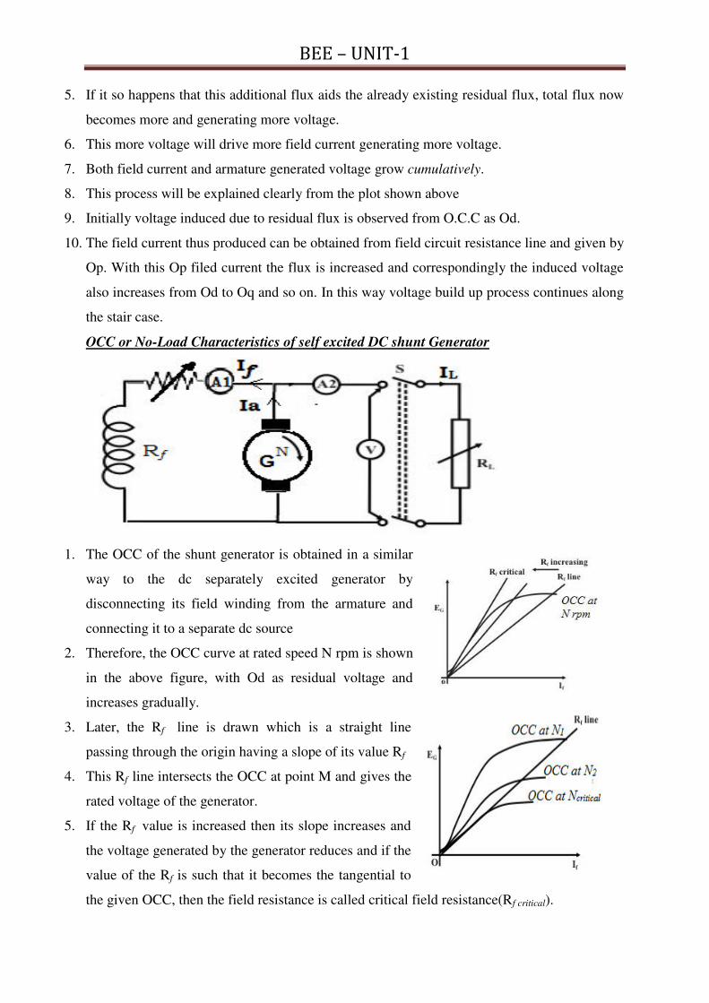
OCC or No-Load Characteristics of self excited DC shunt Generator
1. The OCC of the shunt generator is obtained in a similar
way to the dc separately excited generator by
disconnecting its field winding from the armature and
connecting it to a separate dc source
2. Therefore, the OCC curve at rated speed N rpm is shown
in the above figure, with Od as residual voltage and
increases gradually.
3. Later, the Rf line is drawn which is a straight line
passing through the origin having a slope of its value Rf
4. This Rf line intersects the OCC at point M and gives the
rated voltage of the generator.
5. If the Rf value is increased then its slope increases and
the voltage generated by the generator reduces and if the
value of the Rf is such that it becomes the tangential to
the given OCC, then the field resistance is called critical field resistance(Rf critical).

BEE – UNIT-1
6. At this critical field resistance, the emf or voltage of the generator will be very small and it
doesn’t generates any voltage if the Rf selected is greater than the Rfc
7. Thus, Rf must be always less than the Rfc
8. Similarly, for the Rf < Rfc, if the speed decreases then also the voltage generated by the
generator reduces.
9. Thus the generator doesn’t generates any voltage at a speed called critical speed for which the
given Rf line will become the tangent for the OCC drawn at Nc and is shown in the fig.
10. If the speed of the generator is made to run less than its critical speed then no emf will be
induced, so the speed must be always greater than the critical speed.
Conditions to build up the emf in the generator:
1. The magnets in the machine must have the residual flux.
2. Field winding connection should be such that the residual flux is strengthened by the field
current in the coil. If due to this, no voltage is being built up, reverse the field terminal
connection.
3. Total field circuit resistance must be less than the critical field resistance.
4. Speed of the generator must be greater than the critical speed.
APPLICATIONS OF D.C.GENERATORS
Separately Excited DC Generators
1. Because of their ability of giving wide range of voltage output, they are generally used for
testing purpose in the laboratories.
2. Separately excited generators operate in a stable condition with any variation in field
excitation. Because of this property they are used as supply source of DC motors, whose
speeds are to be controlled for various applications. Example- Ward Leonard Systems of
speed control.
Applications of Shunt Wound DC Generators
The application of shunt generators is very much restricted for its dropping voltage
characteristic.
They are used to supply power to the apparatus situated very close to its position.
These types of DC generators generally give constant terminal voltage for small distance
operation with the help of field regulators from no load to full load.
1. They are used for general lighting.
2. They are used to charge battery because they can be made to give constant output voltage.

BEE – UNIT-1
3. They are used for giving the excitation to the alternators.
4. They are also used for small power supply (such as a portable generator).
Applications of Series Wound DC Generators
These types of generators are restricted for the use of power supply because of their
increasing terminal voltage characteristic with the increase in load current from no load to
full load.
They give constant current in the dropping portion of the characteristic curve. Because of this
property they can be used as constant current source and employed for various applications.
1. They are used for supplying field excitation current in DC locomotives for
regenerative breaking.
2. These are used as boosters to compensate the voltage drop in the feeder in various types of
distribution systems such as railway service.
3. In series arc lightening this type of generators are mainly used.
Applications of Compound Wound DC Generators
Among various types of DC generators, the compound wound DC generators are most
widely used because of its compensating property.
Depending upon number of series field turns, the cumulatively compounded generators may
be over compounded, flat compounded and under compounded.
Thus the desired terminal voltage can be obtained by compensating the voltage drop due to
armature reaction and ohmic drop in the in the line.
Such generators have various applications.
1. Cumulative compound wound generators are generally used for lighting, power
supply purpose and for heavy power services because of their constant voltage
property. They are mainly made over compounded.
2. Cumulative compound wound generators are also used for driving a motor.
3. For small distance operation, such as power supply for hotels, offices, homes and
lodges, the flat compounded generators are generally used.
4. The differential compound wound generators, because of their large demagnetization
armature reaction, are used for arc welding where huge voltage drop and constant
current is required.

BEE – UNIT-1
WORKING PRINCIPLE OF DC MOTOR
A dc motor is a electro mechanical energy conversion device that converts electrical energy
into mechanical energy.
Its operation is based on the principle that “when a current carrying conductor is placed in a
magnetic field, the conductor experiences a mechanical force”.
The direction of the force is given by Fleming’s left hand rule which states that “ Stretch the
first three fingers of left hand mutually perpendicular to each other in such a way that central
finger indicates the direction of the current in the conductor, fore finger in the direction of the
magnetic field, then the thumb indicates the direction of the force developed on the conductor
The magnitude of the force developed on the conductor is F = BIL Sinθ
BACK EMF
When the armature of a d.c. motor rotates under the influence of
the driving torque, the armature conductors move through the
magnetic field and hence an e.m.f. is induced in them as per
Faradays laws of electromagnetic induction.
This induced e.m.f. acts in opposite direction to the applied
voltage V (Lenz’s law) and is known as back or counter e.m.f. Eb .
Significance of Back E.M.F
The presence of back e.m.f. makes the d.c. motor a self-regulating machine i.e., it makes the
motor to draw as much armature current as is just sufficient to develop the torque required by
the load. Back e.m.f. in a d.c. motor regulates the flow of armature current i.e., it
automatically changes the armature current to meet the load requirement.
ARMATURE TORQUE OF A DC MOTOR
Torque is the turning and twisting moment of a force about an axis and is measured by the
product of force (F) and radius (r) at right angle to which the force acts i.e T = F*r
Let
T = Torque developed on the rotor of the motor in Nm
Φ = Flux per pole in weber
Z = No. of the armature conductors
Ia= Armature current in A
P = No. of poles
A = No. of Parallel paths
r = radius of the pulley in mts
Work done by the pulley, W= Force * distance = F * 2πr

BEE – UNIT-1
Power = time
donework TPT
NTrF
NNrF
N
rF
60
2)*(
60
2
60
2
/60
2P
As, power developed in the armature is the gross mechanical power and is given by
ag IEP , therefore TIE ag
A
PZNNTI
A
PZNa
60E
60
2
60g
A
PZIT
IA
PZT
TIA
PZ
a
a
a
2
1
2
2
Also, from the fundamentals, the gross torque or armature torque is
N
P
N
IE
N
IE
N
IEIET
TIETP
mabababab
ab
55.955.9*2
60
2
60*
Also, the shaft torque or useful torque is
N
P
N
PMechlossPPT
TP
shshmshsh
shsh
55.9*2
60
Therefore,
aIT
Torque relations in a dc motor
11
22
2
2
a
a
I
I
T
T
Speed of a DC Motor

BEE – UNIT-1
Therefore,
In a dc motor speed is directly proportional to back emf, Eb and inversely proportional to
flux, φ. TYPES OF D.C. MOTORS
Based on the field winding excited from the armature the dc motors are of three types
1. DC Shunt motor
2. DC Series motor
3. DC compound motor
a. Long Shunt Compound motor
b. Short Shunt Compound motor
DC SHUNT MOTOR
1. In the dc shunt motor the field winding circuit is
connected in parallel to the armature circuit and as
well as to the line.
2. The line current IL is divided in to the field and the
armature as If and Ia.
3. The shunt field winding has more number of turns
with thin wire, so that resistance of the field will be
in the range of hundreds and was designed to
withstand for the rated voltage.
4. Applying KVL to the armature loop the Eg is
brushaaLb VRIVE
fLa III and V
PI L
L and f
fR
VI
DC SERIES MOTOR
3. In the dc series motor the field winding circuit is connected in series to the armature circuit
and as well as to the line.
4. Here the armature current is equal to the series field current
and also equal to the line.
7. The series field winding has less number of turns with
thick wire, so that resistance of the field will be in the
smaller values and was designed to carry the rated current.
8. Applying KVL to the armature loop the Eg is
brushseaaLb VRRIVE
seLa III and V
PI L
L

BEE – UNIT-1
DC COMPOUND MOTORS
4. A compound motor has two field coils wound over the field poles.
5. The coil having large number of turns and thinner cross sectional area is called the shunt field
coil and the other coil having few numbers of turns and large cross sectional area is called the
series field coil.
6. Based on the series field winding connected to the armature the compound motors are
classified as long shunt motor and short shunt motor
SHORT SHUNT MOTOR
4. In a short shunt dc compound motor, the series field is
connected in series to the line and shunt field winding
is connected in parallel to the armature and the series
combination of the line and series winding.
5. Thus, the series field current will depend on the line
variations which will effect in further the shunt field
current.
6. Applying KVL to the armature loop the Eg is
brushseLaaLb VRIRIVE
fLa III and V
PI L
L and
f
seLLf
R
RIVI
LONG SHUNT MOTOR
3. In a long shunt dc compound motor, the series field is
connected in series to the armature and shunt field
winding is connected in parallel to the armature and to
the line.
4. Applying KVL to the armature loop the Eg is
brushseaaLb VRRIVE
fLa III and V
PI L
L and f
fR
VI
Also, the dc compound motors are further classified into two types based on the
compounding of the series flux to the shunt flux. They are cumulatively compounded and
differentially compounded motors
In the cumulatively compound motor, the series flux aids to the shunt field flux and the net
flux increases, whereas in the differentially compounded motors the series flux opposes the
shunt field flux and the net resultant flux decreases.
The below figure shows the arrangement of the series and shunt field coils in the pole core in
both cumulative and differentially compounded motors.

BEE – UNIT-1
APPLICATIONS OF D.C. MOTORS
1. Shunt motors
The characteristic of a shunt motor is an approximately constant speed motor. So, it is used
where the speed is required to remain almost constant from no-load to full-load
Industrial applications of shunt motor:
1. Lathes
2. Drills
3. Boring mills
4. Shapers
5. Spinning and weaving machines etc.
2. Series motors
It is a variable speed motor i.e., speed is low at high torque and vice-versa. It is used
(i) Where large starting torque is required e.g., in elevators and electric Traction
(ii) Where the load is subjected to heavy fluctuations and the speed is automatically required
to reduce at high torques and vice-versa
Industrial applications of series motor:
1. Electric traction 2. Cranes
3. Elevators, 4. Air compressors,
5. Vacuum cleaners 6. Hair drier 7. Sewing machines etc.
3. Compound motors
Differential-compound motors are rarely used because of their poor torque characteristics.
However, cumulative-compound motors are used where a fairly constant speed is required
with irregular loads or suddenly applied heavy loads.
Industrial applications of Compound motor:
1. Presses,
2. Shears,
3. Reciprocating machines etc.

BEE – UNIT-1
LOSSES IN DC MACHINE
Power Stages in DC Generator:
The power stages in a d.c. generator are represented diagrammatically in below Fig.
Mechanical Input - Electrical Power generated = A - B = Iron and friction losses
Electrical Power generated - Electrical Power output = B - C = Copper losses
Efficiency is defined as the ratio of output power to the input power
Electrical efficiency, ɳe = C/B
Mechanical efficiency, ɳm = B/A
Overall efficiency, ɳc = C/A
Therefore, Overall efficiency = Electrical efficiency * Mechanical efficiency
Power Stages in DC Motor:
The power stages in a d.c. motor are represented diagrammatically in below Fig.
Electrical Power input – Mechanical power developed = A - B = Copper losses
Mechanical power developed - Mechanical power output = B - C = Iron and friction losses
Electrical efficiency ɳe = B/A
Mechanical efficiency ɳm = C/B
Overall efficiency ɳc = C/A
BEE – UNIT-1
Condition for maximum efficiency for dc motor:
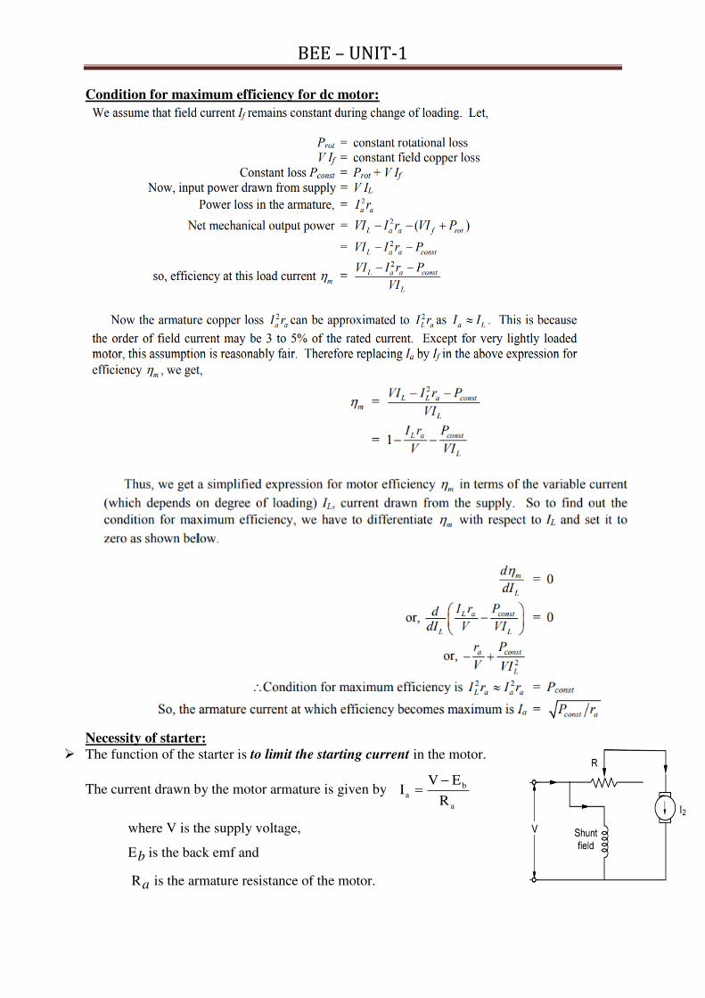
Necessity of starter:
The function of the starter is to limit the starting current in the motor.
The current drawn by the motor armature is given by a
b
aR
EVI
where V is the supply voltage,
Eb is the back emf and
Ra is the armature resistance of the motor.

BEE – UNIT-1
At starting, when motor is at rest there is no back emf in the armature (since Eb α N)
Now the total supply voltage is applied across the stationary armature and it will draw a very
large current because of small armature resistance.
Consider the case of 440 V, 5 HP (3.73 KW) motor having a cold armature resistance of 0.25
and full load current of 50A.
If this motor is started from the line directly, it will draw a starting current of Fehler! = 1760
A which is Fehler! = 35.2 times its full-load current.
This excessive current will blow out the fuses and damages the commutator and brushes. To
avoid this, a resistance is placed in series to the armature for the time duration until the motor
pickups the speed.
Once the motor pickups the speed, the back emf is developed and the current was limited by
the small voltage (VL-Eb) applied to the armature against the small resistance.
Thus, the starter is used to limit this starting current by inserting the resistance only at the
starting time.
There are three types of starters used namely
3 point starter b) Four point starter c) Two point starter
THREE POINT STARTER
The 3 terminals of the three point starter are marked A, B and C.
First terminal A is connected to the handle arm (L) through the overload release (OLR) from
the supply terminals
Second terminal B is connected to the field winding of the motor through the Hold ON coil
from the stud 1 of the external resistance placed in series to the armature.
Third terminal C is connected to the armature by inserting the external resistance.
The handle initially is at OFF position and when the supply is given, to start the motor the
handle is dragged towards the stud 1.
This position of the handle divides the line current into two paths one path to the armature
through the current limiting resistance and second path to the field winding.
Thus the current is limited by this resistance placed in series with the armature. Also as the
speed picks up, the handle was dragged over the studs from off position to ON position.
At this ON position all the external resistance is removed from the armature and the spring on
the other side of the handle develops the restraining torque with the spring placed.
The soft iron piece (S) on the handle is attracted by the hold on coil in normal running
conditions

BEE – UNIT-1
The resistance that was removed from the armature circuit will be added to the field circuit.
Thus the field current is reduced, to overcome the drawback of weakening of the flux the
field winding terminal is connected from the brass arc placed below the studs and is shown in
the figure
Hold ON coil (or) No Volt Release (NVR)
The Normal function of the HOLD-ON coil is to hold on the arm in then full running position
when the motor is in normal operation.
When the supply failure (or) disconnection, it is de-energised, so that handle is released from
the hold on coil and pulled back by the spring to the OFF position.
The Hold ON coil protects the motor from dangerous speed when field circuit opens.
Over Load Release (OLR)
It consists of an electro-magnet connected in the supply line.
If motor becomes over loaded, then D is lifted and short circuits the electro-magnet. Hence
arm is released and returns to OFF position.
Disadvantage of three point starter:
To control the speed of motor, a field rheostat is connected in the field circuit.The motor
speed is increased by decreasing the flux (N I/). There is a difficulty that if too much
resistance is added by the field rheostat, then field current is reduced very much so that the
current in the hold on coil is unable to create enough Electromagnetic pull to overcome the
spring tension. Hence arm is pulled back to OFF position.
Therefore the shunt motor with this three point starter is not suitable for adjustable speed
drive applications.
Speed control of DC motors:
The speed of a d.c. motor is given by:

BEE – UNIT-1
Eb
N or RIV
N aL where R is Ra for shunt motor and (Ra + Rse). for series motor
From the above expression,
The speed of a d.c. motor is controlled
(i) By varying the flux per pole (f) known as flux control method.
(ii) By varying the Ra and is known as armature control method.
(iii) By varying the applied voltage V and is known as voltage control method.
Speed Control of D.C. Shunt Motor
a) Field control method:
1. In this field control method the variable is flux (f)
2. The rheostat is placed in series to the field winding, as the field resistance increases
the field current decreases and this weakens the flux
3. The weakening of the flux increases the speed since speed is inversely proportional to
the flux.
4. Thus using the field control, above base speeds can be controlled.
5. This method is also known as constant power method or variable torque method.
Advantages
1. This is an easy and convenient method.
2. It is an inexpensive method since very little power is wasted in the shunt field rheostat
due to relatively small value of If
3. The speed control exercised by this method is independent of load on the machine.
Disadvantages
1. Only speeds higher than the normal speed can be obtained.
2. There is a limit to the maximum speed obtainable by this method. It is because if the
flux is too much weakened, commutation becomes poorer.
b) Armature control method
1. In this armature resistance control method the variable is Ra
2. The rheostat is placed in series to the armature winding, as the Ra increases the IaRa
drop increases and this decreases the speed.
3. The decreasing of the back emf decreases the speed since speed is directly
proportional to Eb.

BEE – UNIT-1
4. Thus using the Ra control method, below base speeds can be controlled.
5. This method is also known as constant torque method or variable power method.
Disadvantages
1. A large amount of power is wasted in the controller resistance since it carries full
armature current Ia.
2. The speed varies widely with load since the speed depends upon the voltage drop in
the controller resistance and hence on the armature current demanded by the load.
3. The output and efficiency of the motor are reduced.
4. This method results in poor speed regulation.
c) Voltage control method by Ward-Leonard system 1. This method is used to get the wide range of speed control 10:1.
2. As the speed of the motor is directly proportional to the applied voltage to the
armature, thus by applying the variable voltage the speed is controlled.
3. The armature of the shunt motor M (whose speed is to be controlled) is connected
directly to a d.c. generator G driven by a constant-speed a.c. motor A.
4. The field of the shunt motor is supplied from a constant-voltage exciter E.
5. The field of the generator G is also supplied from the exciter E.
6. The voltage of the generator G can be varied by means of its field regulator.
7. By reversing the field current of generator G by controller FC, the voltage applied to
the motor may be reversed.
Advantages 1. The speed of the motor can be adjusted through a wide range without resistance losses
which results in high efficiency.
2. The motor can be brought to a standstill quickly, simply by rapidly reducing the
voltage of generator G.
3. The disadvantage of the method is that a special motor-generator set is required for
each motor and the losses in this set are high if the motor is operating under light
loads for long periods.
Speed Control of D.C. Series Motor
a) Flux control method In this method, the flux produced by the series motor is varied
and hence the speed.
The variation of flux can be achieved in the following ways:
(i) Field diverters. 1. In this method, a variable resistance (called field diverter) is
connected in parallel with series field winding as shown in Fig.
2. Its effect is to shunt some portion of the line current from the
series field winding, thus weakening the field and increasing the
speed (Nα1/Φ). 3. This method can only provide speeds above the normal
speed. The series field diverter method is often employed in
traction work.
ii) Armature diverter.
1. In order to obtain speeds below the normal speed, a variable
resistance (called armature diverter) is connected in parallel
with the armature as shown in Fig.
2. The diverter shunts some of the line current, thus reducing
the armature current.
3. Now for a given load, if Ia is decreased, the flux Φ must increase (TαΦIa).

BEE – UNIT-1
4. Since (Nα1/Φ). The motor speed is decreased. 5. By adjusting the armature diverter, any speed lower than the normal speed can be obtained.
iii) Tapped field control.
1. In this method, the flux is reduced by decreasing the number of
turns of the series field winding as shown in Fig, and hence
speed is increased
2. The switch S can short circuit any part of the field winding,
thus decreasing the flux and raising the speed.
3. With full turns of the field winding, the motor runs at normal
speed and as the field turns are cut out; speeds higher than
normal speed are achieved.
iv) Paralleling field coils.
This method is usually employed in the case of fan motors. By regrouping the field coils as
shown in Fig below, several fixed speeds can be obtained.
b) Armature-resistance control:
1. In this method, a variable resistance is directly connected in
series with the supply to the complete motor as shown in
Fig.
2. This reduces the voltage available across the armature and
hence the speed falls.
3. By changing the value of variable resistance, any speed
below the normal speed can be obtained.
4. This is the most common method employed to control the
speed of d.c. series motors.
5. Although this method has poor speed regulation, this has no
significance for series motors because they are used in varying speed applications.
6. The loss of power in the series resistance for many applications of series motors is not too
serious since in these applications.
TESTING OF DC MACHINES:
Testing of DC machines can be broadly classified as
i) Direct method of Testing
ii) Indirect method of testing
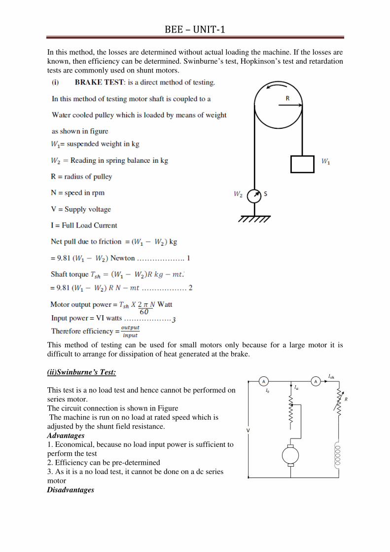
Direct method of testing: In this method, the DC machine is loaded directly by means of a brake applied to water
cooled pulley coupled to the shaft of the machine. The input and output are measured and
efficiency is determined by input
output
It is not practically possible to arrange loads for machines of large capacity.
Indirect method of testing:
BEE – UNIT-1
In this method, the losses are determined without actual loading the machine. If the losses are
known, then efficiency can be determined. Swinburne’s test, Hopkinson’s test and retardation
tests are commonly used on shunt motors.
This method of testing can be used for small motors only because for a large motor it is
difficult to arrange for dissipation of heat generated at the brake.
(ii)Swinburne’s Test:
This test is a no load test and hence cannot be performed on
series motor.
The circuit connection is shown in Figure
The machine is run on no load at rated speed which is
adjusted by the shunt field resistance.
Advantages
1. Economical, because no load input power is sufficient to
perform the test
2. Efficiency can be pre-determined
3. As it is a no load test, it cannot be done on a dc series
motor
Disadvantages
BEE – UNIT-1
1. Change in iron loss from no load to full load is not taken into account. (Because of
armature
reaction, flux is distorted which increases iron losses).
2. Stray load loss cannot be determined by this test and hence efficiency is over estimated.
3. Temperature rise of the machine cannot be determined.
4. The test does not indicate whether commutation would be satisfactory when the machine is
loaded.

BEE – UNIT - 2
1
Unit – 2 (BEE) R -19 Regulations – I ECE II Semester
Transformers: Principle of operation of single phase transformer constructional features –
EMF equation – Losses and efficiency of transformer- regulation of transformer – OC & SC
tests predetermination of efficiency and regulations – Sumpner’s test-Numerical Problems.
1. Explain the Working principle of transformer
1. The basic working principle of a
transformer is mutual induction
between two windings linked by
common magnetic flux.
2. The primary and secondary coils
are electrically separated but
magnetically linked to each other.
3. When, primary winding is
connected to a source of alternating
voltage, alternating magnetic flux is
produced around the winding.
4. The core provides magnetic path
for the flux, to get linked with the
secondary winding. Most of the flux gets linked with the secondary winding which is called
as 'useful flux' or main 'flux', and the flux which does not get linked with secondary winding
is called as 'leakage flux'.
5. As the flux produced is alternating (the direction of it is continuously changing), EMF gets
induced in the secondary winding according to Faraday's law of electromagnetic induction.
This induced emf is called 'mutually induced emf', and the frequency of mutually induced
emf is same as that of supplied emf. Thus, in a transformer the frequency is same on both
sides.
6. If the secondary winding is closed circuit, then mutually induced makes the current flow
through it, and hence the electrical energy is transferred from one circuit (primary) to another
circuit (secondary).
2. Derive the EMF Equation of a Transformer Let
ϕm = Maximum value of flux in Weber
f = Supply frequency in Hz
N1 = Number of turns in the primary winding
N2 = Number of turns in the secondary winding
Φ = flux per turn in Weber As per the faradays laws,
The average value of the emf induced is directly proportional to the rate of change of
flux.
The flux changes from + ϕm to – ϕm in half a cycle of 1/2f seconds.
Flux increases from its zero value to maximum value ϕm in one quarter of the cycle
i.e. in ¼ of the timeperiod.
Average rate of change of flux is f
f
dt
dm
m
4
4
1
0
volts

BEE – UNIT - 2
2
Therefore the average e.m.f per turn is fm4
As 11.1 FormfactorueAverageval
Rmsvalue for sinusoidal varying quatities
Hence, RMS value of e.m.f/turn is ff mm 44.44*11.1
RMS value of e.m.f in the primary & secondary winding. =( e.m.f/turn) * No:of turns
Therefore Emf induced in primary winding having N1turns is 11 44.4 fNE m
Emf induced in secondary winding having N2 turns is 22 44.4 fNE m
3. Explain the Construction of Transformer
1. The simple construction of a transformer, need two coils having mutual inductance and a
laminated steel core.
2. The two coils are insulated from each other and from the
steel core.
3. The device will also need some suitable container for the
assembled core and windings, a medium with which the
core and its windings from its container can be insulated.
4. In order to insulate and to bring out the terminals of the
winding from the tank, bushings made of porcelain are
used.
5. In all transformers, the core is made of transformer sheet
steel laminations assembled to provide a continuous
magnetic path with minimum of air-gap included.
6. The steel should have high permeability and low hysteresis loss. For this to happen, the steel
should be made of high silicon content and must also be heat treated.
7. By effectively laminating the core, the eddy-current losses can be reduced. The lamination
can be done with the help of a light coat of core plate varnish or lay an oxide layer on the
surface. For a frequency of 50 Hertz, the thickness of the lamination varies from 0.35mm to
0.5mm for a frequency of 25 Hertz.
8. To reduce the leakage fluxes in the transformer the windings of the primary and secondary
coils are interleaved in the core type and sandwiched coils in the shell type.
9. To reduce the volume of the cu wire the core used must be the stepped core or cruciform
core.
4. Compare and distinguish the types of transformers
There are two major types of transformers based on construction. 1. Core type 2. Shell type
S.No Core type Transformer Shell type transformer
1 The winding encircles the core The core encircles the winding
2 The cylindrical type of coils are used Generally multilayer disc type or
sandwiched coils coils are used
3 As windings are distributed, the
natural cooling is more effective
As windings are surrounded by the core,
the natural cooling does not exists.
4 The coils can be easily removed from
the maintenance point of view
For removing any winding for
maintenance, a large number of laminations
are to be removed. This is difficult.
5 The construction is preferred for low
voltage transformers
The construction is used for very high
voltage transformers
6 It has a single magnetic core It has a double magnetic core
7 In a single phase type there are two
limbs
In a single phase type the core has three
limbs

BEE – UNIT - 2
3
5. Explain the operation of Transformer on No Load.
Ideal transformer at No-Load:
1. The transformer operating at no load, is equivalent to the secondary winding kept open
circuited, which means current in the secondary is zero.
2. When primary winding is excited at its rated voltage it draws a current Im called magnetizing
current which is 2 to 10% of the rated current. This generates the magnetic flux in the core by
primary mmf N1Im
3. As the transformer is ideal, the core loss and cu loss are zero. And the net current taken is to
create the mmf or flux of alternating nature.
4. This alternating flux induces the emf’s E1 and E2 in the coils which lags the flux by 900
5. The Im is inphase to the flux and the applied voltage leads to the Im by 900 being the coil with
pure inductive type.
6. Hence, emf’s E1 and E2 in the coils are inphase to each other and lags the flux by 900
Ideal Transformer at No-Load
Transformer at No-Load:
1. The transformer in the practical case draws an additional current Iw to the magnetizing
current Im and total current from the supply mains is I0 which lags to the applied voltage by
an angle Φ0
2. There are two components of the current in I0 namely
i. Active (or) power (or) Watt full component of the current Iw which is in phase to the
voltage, and generates the core loss in the transformer
ii. Reactive (or) Watt less (or) magnetizing component of the current Im which lags to the
voltage by 900, and magnetizes the core in the transformer
3. Also, the no-load input power of the transformer is the iron loss (since the cu loss are small at
no-load)
4. The no load angle (Φ0) depends upon the losses in the transformer and is nearly equal to 900.
So that the power factor is very low and varies from 0.1 to 0.15 lagging.

BEE – UNIT - 2
4
6.
6. Explain the operation of Transformer on Load without leakage impedances of the
coils.
1. When an electrical load is connected to the secondary winding of a transformer a current
flows in the secondary winding.
2. This secondary current is due to the induced secondary voltage, set up by the magnetic flux Φ in the core from the primary current(I0) and the main flux direction is from primary coil to
secondary coil (clockwise)
3. The secondary current, I2 which is determined by the characteristics of the load, creates an
secondary or load mmf (N2I2) and a secondary magnetic field, Φ2 is established in the
transformer core which flows in the exact opposite direction to the main primary field, Φ1. i.e
Φ2 is in anti clock wise.
4. These two magnetic fields oppose each other resulting in a combined magnetic field of less
magnetic strength than the single field produced by the primary winding alone when the
secondary circuit was open circuited.

BEE – UNIT - 2
5
5. This in turn decreases the primary induced emf and leads to the increase in primary current
I1=I0+I21.
6. This additional I21 current is called load component current in the primary and will be in such
a way to balance the load mmf by this mmf on the primary
i.e N2I2=N1I21 therefore I2
1= I2K where, K = N2/N1
7. This N1I21 will produce a flux Φ2
1 equal and opposite to Φ2. These fluxes will now be
cancelled and the net flux in the core will be Φ1 even under the loading conditions.
8. For lagging load: I12
= I02
+ (I21)2
+ 2I0I21cos(Φ0~ Φ2)
9. As the flux remains constant from no-load to load, the iron loss will be same from no-load to
load.
7. Explain the operation of transformer on load with leakage impedances of the coils
1. Below figure shows the schematic diagram, equivalent circuit and phasor diagram of the
transformer with the leakage impedances of the coils.
Let,
R1=Resistance of primary coil in Ω R2=Resistance of secondary coil in Ω
X1=Reactance of primary coil in Ω X2=Reactance of secondary coil in Ω
Z1=impedance of primary coil in Ω Z2=impedance of secondary coil in Ω
E1=emf induced in primary coil E2=emf induced in secondary coil
V1=applied voltage to primary coil V2= Load or terminal voltage of transformer
I1Z1 = I1(R1+jX1) = Primary leakage impedance drop
I2Z2 = I2(R2+jX2) = Secondary leakage impedance drop
The magnetic core of the transformer is electrically represented with the parallel
combination of R0 and X0 carrying the currents of Iw and Im respectively and is placed
across the primary coil.

BEE – UNIT - 2
6
Currents Analysis of the transformer in equivalent circuit
Currents in the transformer at No-load:
0
1
R
VI w
0
1
X
VI m 222
0 mw III 22
0 mw III
w
m
I
I1
0 tan
Currents in the transformer with load
2
1
2001 III Where KII 2
1
2 and 1
2
N
NK
2
1
2002
1
2001 sinsincoscos IIjIII - for lag and + for lead
Primary phase angle (Φ1)
2
1
200
2
1
2001
1coscos
sinsintan
II
IIand primary power factor is cosΦ1
Voltages Analysis of the transformer in equivalent circuit
Primary induced emf
11111111 sincos0 jXRjIIjVE
Using transformation ratio E2=E1*K
Knowing the E2 and applying KVL to the secondary loop the load voltage is
22222 ' ZIEV )(' 222222 jXRIEV
11111 0 ZIVE
2222 ZIEV

BEE – UNIT - 2
7
8. Explain the equivalent circuits referred to both primary and secondary of the
transformer
The equivalent circuit of the transformer referred to primary is shown in the below figure in
which the winding parameters of the secondary are transformed and was referred to primary
based on the voltage balancing principle before and after the transformation.
Secondary Resistance referred to primary:
2
2
2
1
2
2
1
2
2
2
2
12
21
22
22
1
1
1
11
2
1 R
I
Valso
KI
I
V
V
K
R
I
V
IV
IV
IV
IV
I
V
I
VR
2
21
2K
RR Thus, it is the secondary resistance referred to primary
Secondary Reactance referred to primary:
2
2
2
1
2
2
1
2
2
2
2
12
21
22
22
1
1
1
11
2
1 X
I
Valso
KI
I
V
V
K
X
I
V
IV
IV
IV
IV
I
V
I
VX
2
21
2K
XX Thus, it is the secondary reactance referred to primary
Secondary Impedance referred to primary:
2
2
2
1
2
2
1
2
2
2
2
12
21
22
22
1
1
1
11
2
1 Z
I
Valso
KI
I
V
V
K
Z
I
V
IV
IV
IV
IV
I
V
I
VZ
2
21
2K
ZZ Thus, it is the secondary impedance referred to primary
To have simplified calculations the equivalent circuit is modified as bringing the core branch
towards the supply voltage instead of having in between the primary and secondary
parameters
In this simplified circuit the total resistance, reactance and impedances referred to primary are

BEE – UNIT - 2
8
2
21
1
211K
RRRRReq
2
21
1
211K
XXXXX eq
2
21
1
211K
ZZZZZeq
Similarly, the equivalent circuit referred to secondary of the transformer is shown below with
their formulas
Primary Resistance referred to secondary:
1
1
1
2
1
1
21
2
1
1
21
12
11
11
2
2
2
21
1 RI
ValsoK
I
I
V
VRK
I
V
IV
IV
IV
IV
I
V
I
VR
2
1
1
1 KRR Thus, it is the primary resistance referred to secondary
Primary Reactance referred to secondary:
1
1
1
2
1
1
21
2
1
1
21
12
11
11
2
2
2
21
1 XI
ValsoK
I
I
V
VXK
I
V
IV
IV
IV
IV
I
V
I
VX
2
1
1
1 KXX Thus, it is the primary reactance referred to secondary
Primary Impedance referred to secondary:
1
1
1
2
1
1
21
2
1
1
21
12
11
11
2
2
2
21
1 ZI
ValsoK
I
I
V
VZK
I
V
IV
IV
IV
IV
I
V
I
VZ
2
1
1
1 KZZ Thus, it is the primary impedance referred to secondary 2
12
1
122 KRRRRReq 2
12
1
122 KXXXXX eq
2
12
1
122 KZZZZZeq
9. Derive the expression for voltage regulation and efficiency of the transformer
Definition of voltage regulation : Voltage regulation is defined as the percentage
change in the output voltage from no-load to full-load expressed in full load voltage.
BEE – UNIT - 2
9
Derivation of voltage regulation for the lagging power factor load, assuming the angle between OC and OD as very small, and neglected it, OD is nearly equal
to OC (E2 > V2)
sincos , 2222222 eqeq XIRIVOCEBCABOAOCE
Thus, the % voltage regulation is
100V
sincos100
V
sincos100*
2
2222
2
222222
2
22
eqeqeqeq XIRIVXIRIV
V
VE
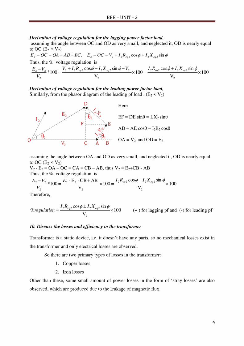
Derivation of voltage regulation for the leading power factor load, Similarly, from the phasor diagram of the leading pf load , (E2 < V2)
Here
EF = DE sinθ = I2X2 sinθ
AB = AE cosθ = I2R2 cosθ
OA = V2 and OD = E2
assuming the angle between OA and OD as very small, and neglected it, OD is nearly equal
to OC (E2 < V2)
V2 - E2 = OA – OC = CA = CB – AB, thus V2 = E2+CB - AB
Thus, the % voltage regulation is
100V
sincos100
V
ABCB-E-100*
2
2222
2
22
2
22
eqeq XIRIE
V
VE
Therefore,
100V
sincos%
2
2222
eqeq XIRI
regulation (+ ) for lagging pf and (-) for leading pf
10. Discuss the losses and efficiency in the transformer
Transformer is a static device, i.e. it doesn’t have any parts, so no mechanical losses exist in
the transformer and only electrical losses are observed.
So there are two primary types of losses in the transformer:
1. Copper losses
2. Iron losses
Other than these, some small amount of power losses in the form of ‘stray losses’ are also
observed, which are produced due to the leakage of magnetic flux.
BEE – UNIT - 2
10
Copper losses
1. These losses occur in the windings of the transformer when heat is dissipated due to the
current passing through the windings and the internal resistance offered by the windings.
2. So these are also known as ohmic losses or I2R losses, where ‘I’ is the current passing
through the windings and R is the internal resistance of the windings.
3. These losses are present both in the primary and secondary windings of the transformer and
depend upon the load attached across the secondary windings since the current varies with the
variation in the load, so these are variable losses.
Iron losses or Core Losses
1. These losses occur in the core of the transformer and are generated due to the variations in
the flux.
2. These losses depend upon the magnetic properties of the materials which are present in the
core, so they are also known as iron losses, as the core of the Transformer is made up of iron.
And since they do not change like the load, so these losses are also constant losses.
There are two types of Iron losses in the transformer:
1. Eddy Current losses
2. Hysteresis Loss
Eddy Current Losses
1. When an alternating current is supplied to the primary windings of the transformer, it
generates an alternating magnetic flux in the winding which is then induced in the secondary
winding also through Faraday’s law of electromagnetic induction, and is then transferred to
the externally connected load.
2. During this process, the other conduction materials of which the core is composed of; also
gets linked with this flux and an emf is induced.
3. But this magnetic flux does not contribute anything towards the externally connected load or
the output power and is dissipated in the form of heat energy.
4. So such losses are called Eddy Current losses and are mathematically expressed as:
Pe = Ke f² Kf² Bm²
Where;
Ke = Constant of Eddy Current
Kf2 = Form Constant
Bm = Strength of Magnetic Field
Hysteresis Loss

BEE – UNIT - 2
11
1. Hysteresis loss is defined as the electrical energy which is required to realign the domains of
the ferromagnetic material which is present in the core of the transformer.
2. These domains loose their alignment when an alternating current is supplied to the primary
windings of the transformer and the emf is induced in the ferromagnetic material of the core
which disturbs the alignment of the domains and afterwards they do not realign properly.
3. For their proper realignment, some external energy supply, usually in the form of current is
required. This extra energy is known as Hysteresis loss.
Mathematically, they can be defined as;
Ph = Kh Bm1.6
f V
The Efficiency of the transformer is defined as the ratio of power output to the input power.
Where,
V2 = Secondary terminal voltage
I2 = Full load secondary current in A
Cosϕ2 = power factor of the load
Pi = Iron losses
= hysteresis losses + eddy current
loss
Pc = Full load copper losses = I22Req
Also, the efficiency at any amount of load(x) is given by
100cos
cos2
FLCui WxWxVA
xVA
tsinputinwat
ttsoutputinwa
Condition for maximum efficiency in the transformer:
coscos1
1
coscos1
1
cos
cos
2
22
2222
2
2
2
22
2
2
222
22
V
rI
IV
W
IV
rI
IV
WrIWIV
IV
tsinputinwat
ttsoutputinwa
eieiei
To get the maximum efficiency the denominator must be small, therefore condition to be the
denominator minimum is
0coscos
1
2
2
22
22
dI
V
rI
IV
Wd ei
0coscos
)(0coscos
1
2
2
2
222
2
22
22
V
r
IV
W
dI
V
rI
IV
Wd
ei
ei
coscos 2
222
2
IV
W
V
r ie 2
2
2I
Wr i
e ie WrI 2
2
2
BEE – UNIT - 2
12
Therefore the condition for obtaining the maximum efficiency is the variable loss 2
2
2 erI
must be equal to the constant loss iW .
Also, the load current at which the maximum efficiency occurs is
2
max2
e
i
r
WI
Multiplying both sides with 1000 *V2
2
2max22 *V* 1000*V* 1000e
i
r
WI
2
2max *V* 1000KVA Loade
i
r
W
2load 2Full
load 2Full2max
I
I*V* 1000KVA Load
e
i
r
W
2
2
load 2Full
load 2Full2maxI
I*V* 1000KVA Loade
i
r
W
2
2
load 2Full
maxI
KVA load FullKVA Loade
i
r
W
load cuFullWKVA load Full efficiency maximumat which KVA Load The iW
’
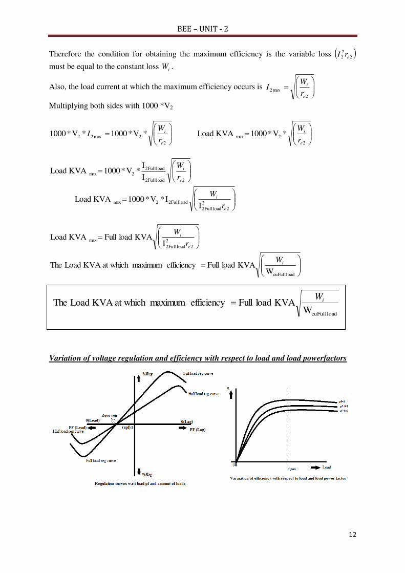
Variation of voltage regulation and efficiency with respect to load and load powerfactors
load cuFullWKVA load Full efficiency maximumat which KVA Load The iW
BEE – UNIT - 2
13
11. Explain OC and SC tests on a single phase transformer
Ans: Purpose of conducting OC and SC tests is to find
i) Equivalent circuit parameters ii) Efficiency iii) Regulation
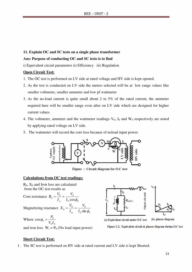
Open Circuit Test:
1. The OC test is performed on LV side at rated voltage and HV side is kept opened.
2. As the test is conducted on LV side the meters selected will be at low range values like
smaller voltmeter, smaller ammeter and low pf wattmeter
3. As the no-load current is quite small about 2 to 5% of the rated current, the ammeter
required here will be smaller range even after on LV side which are designed for higher
current values.
4. The voltmeter, ammeter and the wattmeter readings V0, I0 and W0 respectively are noted
by applying rated voltage on LV side.
5. The wattmeter will record the core loss because of noload input power.
Calculations from OC test readings:
R0, X0 and Iron loss are calculated
from the OC test results as
Core resistance 00
00
0cosI
V
I
VR
w
Magnetizing reactance 00
00
0sin I
V
I
VX
m
Where 00
0
0cosIV
P
and iron loss Wi = P0 (No load input power)
Short Circuit Test:
1. The SC test is performed on HV side at rated current and LV side is kept Shorted.

BEE – UNIT - 2
14
2. As the test is conducted on HV side the meters selected will be at low range values like
smaller voltmeter, smaller ammeter and unity pf wattmeter
3. As the voltage required to circulate the short circuit rated current is very small about 10 to
15% of the rated HV voltage, so the voltmeter required here will be smaller range even the
test is conducted on HV side.
4. The voltmeter, ammeter and the wattmeter readings Vsc, Isc and Wsc respectively are noted by
passing rated current on HV side.
5. The wattmeter will record thecopper loss corresponding to the Isc.
Calculations from SC test readings:
re(HV), xe(HV) and cu loss are calculated
from the SC test results as
Equivalent resistance referred to HV side is
)(2 HVe
sc
sc
sc rI
PR
Equivalent impedance referred to HV side is
)(HVe
sc
sc
sc zI
VZ
Equivalent reactance referred to HV side is )(
22
HVescscsc xRZX
The culoss is equal to the wattmeter reading Wsc
Thus, the approximate equivalent circuit of the transformer can be drawn by the calculated
values of R0 and X0 on LV side and re(HV) and xe(HV) on HV side.
The efficiency at any load is calculated from the losses Wi and Wcufl as
100cos
cos2
FLCui
xWxWxVA
xVA
The regulation of the transformer is calculated from the re(HV) and xe(HV) as
pf leadingfor isand pf laggingfor is where100V
sincos%
HV
eHVHVeHVHV xIrI
reg
BEE – UNIT - 2
15
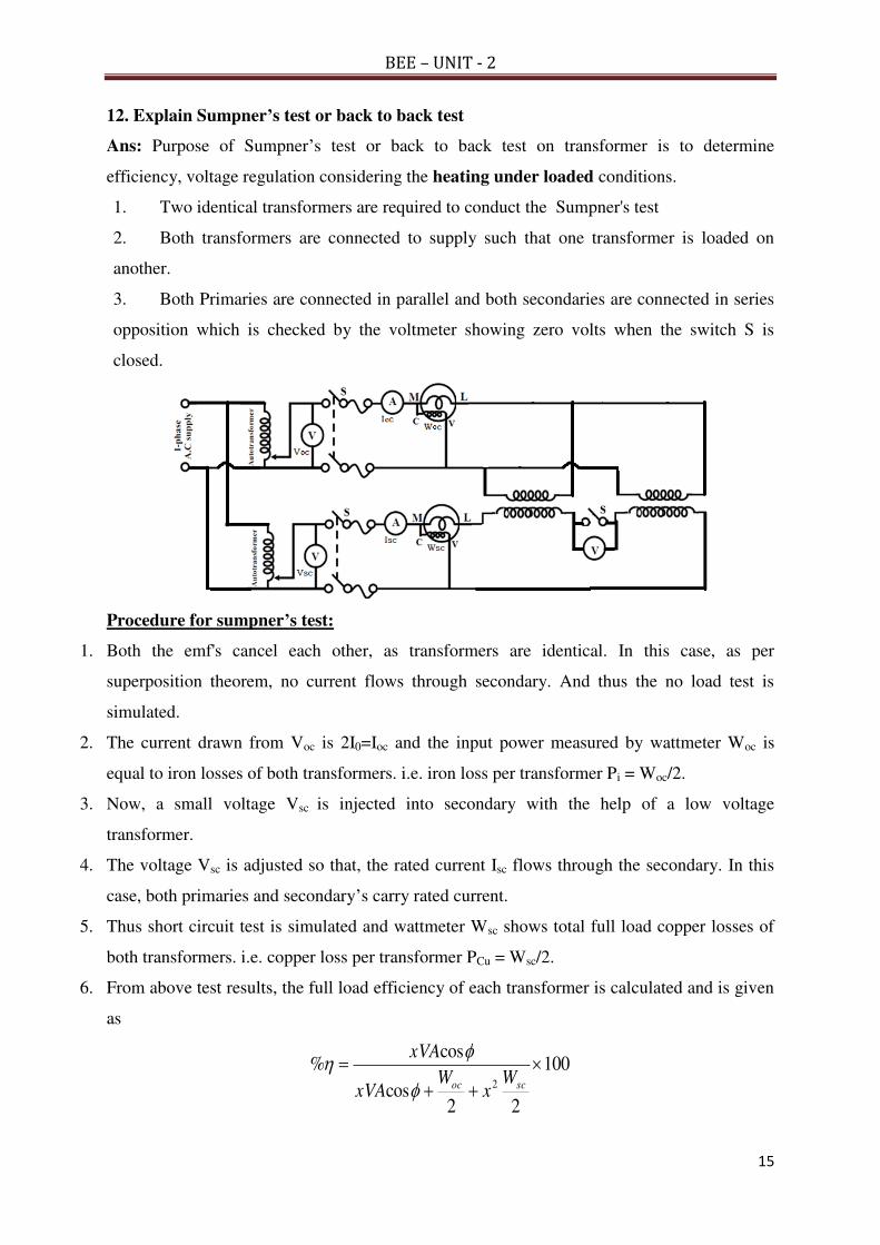
12. Explain Sumpner’s test or back to back test
Ans: Purpose of Sumpner’s test or back to back test on transformer is to determine
efficiency, voltage regulation considering the heating under loaded conditions.
1. Two identical transformers are required to conduct the Sumpner's test
2. Both transformers are connected to supply such that one transformer is loaded on
another.
3. Both Primaries are connected in parallel and both secondaries are connected in series
opposition which is checked by the voltmeter showing zero volts when the switch S is
closed.
Procedure for sumpner’s test:
1. Both the emf's cancel each other, as transformers are identical. In this case, as per
superposition theorem, no current flows through secondary. And thus the no load test is
simulated.
2. The current drawn from Voc is 2I0=Ioc and the input power measured by wattmeter Woc is
equal to iron losses of both transformers. i.e. iron loss per transformer Pi = Woc/2.
3. Now, a small voltage Vsc is injected into secondary with the help of a low voltage
transformer.
4. The voltage Vsc is adjusted so that, the rated current Isc flows through the secondary. In this
case, both primaries and secondary’s carry rated current.
5. Thus short circuit test is simulated and wattmeter Wsc shows total full load copper losses of
both transformers. i.e. copper loss per transformer PCu = Wsc/2.
6. From above test results, the full load efficiency of each transformer is calculated and is given
as
100
22cos
cos%
2
scoc W
xW
xVA
xVA

BEE – UNIT - 3
1
Unit – 3 (BEE) R -19 Regulations – I ECE II Semester
Synchronous Generators: Principle of operation and construction of alternators – types of alternators
Regulation of alternator by synchronous impedance method-EMF equation of three phase alternator.
Synchronous Motors: Construction of three phase synchronous motor - operating principle –
equivalent circuit of synchronous motor.
ALTERNATOR - WORKING PRINCIPLE
Synchronous generator or AC generator is a device which converts mechanical power in the form of
A.C.
It works on the principle of ELECTRO MAGNETIC INDUCTION and it is also called as Alternator.
An alternator consists of armature winding and field magnet, but the difference between the alternator
and DC generator is that in the DC generator armature rotates and the field system is stationary.
This arrangement in the alternator is just reverse of it, the armature is stationary called as stator and
field system is rotating called as Rotor.
For generating EMF, three things are essential:
1) Magnetic field
2) System of conductors
3) Relative motion between those two.
The conductors are mounted on the stator and the field poles are mounted on the Rotor core
Relative motion between the stator conductors and the field is brought about rotating the field
system.
The rotor is coupled mechanically to a suitable prime mover. When the prime mover runs, the
rotor core also rotates and the field flux is cut by the stationary stator conductors and emf’s are
induced in them.
If a load is connected across the stator terminals electric power would be delivered to it.
Advantages of Stationary Armature
1. The generated power can be easily taken out from the stator.
2. There is no possibility of the armature conductors flying of, when the machine runs at
high speed since they are housed in the stator slots.
3. There is no difficulty in insulating the armature (stationary) winding for very high voltages,
i.e, as high as 30000v or more.
4. Two slip rings are required for the supply of DC energy required for rotor field excitation.
Since exciting current is to be supplied at low voltage, there is no difficulty in insulating
them.

BEE – UNIT - 3
2
5. Rotating field is competitively light and can run with high speeds.

BEE – UNIT - 3
3
Differences between stationary and rotating field systems:
S.No. STATIONARY FIELD SYSTEM ROTATING FIELD SYSTEM
1 4 slip rings are required. 100 slip rings are required.
2 Heavy armature current passes through
slip rings.
Very low field current passes through slip
rings.
3 More sparking at slip rings. No sparking at slip rings.
4 Armature supply is taken through slip
rings.
Armature supply is taken through fixed
connections.
5 Capacity is limited to 30KVA. It can be designed to any capacity.
6 Voltage is limited to 440v. Voltage is up to 33KV is generated.
7 Low efficiency. High efficiency.
8 More maintenance. Less maintenance.
CONSTRUCTION OF ALTERNATOR
An alternator consists of mainly two parts
1. Stator
2. Rotor
Stator:
1. The armature core is supported by the stator
frame and is built up of laminations of special
magnetic iron or steel iron alloy, the core is
laminated to minimize the loss due to Eddy
currents.
2. The laminations are stamped out in complete
rings or segments. The laminations are insulated
from each other and have space between them for allowing the cooling air to pass through.
3. The inner periphery of the stator is slotted and copper conductors which are joined to one
another constituting armature winding housed in these slots.
4. The other ends of the winding are brought out are connected to fixed terminal from which
the generator power can be taken out.
5. Different shapes of the armature slots are available
a. The wide open type slot also used in DC machines has the advantage of permitting easy
installation of form-wound colis and there easy removal in case of repair but it has the

BEE – UNIT - 3
4
disadvantage of distributing the air gaps flux into bunches that produce ripples in the
wave of generated EMF.
b. The semi closed type slots are better in this respect but do not allow the use of form
wound coils.
c. The fully closed slots do not disturb the air gap flux but they try to increase the
inductance of the windings. The armature conductors have to be threaded through,
thereby increasing the initial labour and cost of the winding. Hence, these are rarely used.
Rotor
Depending upon the type of application, these are classified into two types
1) Salient-pole or projecting pole type
2) Non silent-pole or round rotor or cylindrical rotor
Salient-pole or projecting pole type
1. It is used for low and medium speed alternators used
in hydro and diesel power generating station.
2. The poles are made of laminated sheets and fixed to
the rotor by dove tail joint.
3. Short circuited damper bars are placed in the slots
provided on the pole surfaces.
4. These are used to prevent hunting and to provide
starting torque in synchronous motors.
5. The field coils are placed on the poles as shown in
the figure
Key features:-
1. It has non-uniform air gap.
2. The diameter of the rotor is more than of the cylindrical rotor.
3. The no. of poles is higher than that of the non salient-pole rotor
4. Axial length is less.
5. The prime mover speed is less and is driven in hydal turbines
6. These generators are used in hydro electric stations so these are called as hydro
generators.
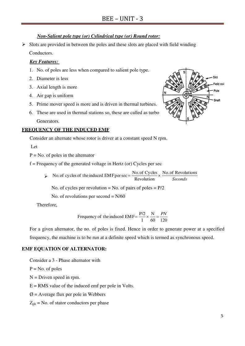
BEE – UNIT - 3
5
Non-Salient pole type (or) Cylindrical type (or) Round rotor:
Slots are provided in between the poles and these slots are placed with field winding
Conductors.
Key Features:
1. No. of poles are less when compared to salient pole type.
2. Diameter is less
3. Axial length is more
4. Air gap is uniform
5. Prime mover speed is more and is driven in thermal turbines.
6. These are used in thermal stations so, these are called as turbo
Generators.
FREQUENCY OF THE INDUCED EMF
Consider an alternate whose rotor is driver at a constant speed N rpm.
Let
P = No. of poles in the alternator
f = Frequency of the generated voltage in Hertz (or) Cycles per sec
Seconds
sRevolution of No.
Revolution
Cycles of No. secper EMF induced theof cycles of No.
No. of cycles per revolution = No. of pairs of poles = P/2
No. of revolutions per second = N/60
Therefore,
12060
N
1
P/2 EMF induced theofFrequency
PN
For a given alternator, the no. of poles is fixed. Hence in order to generate power at a specified
frequency, the machine is to be run at a definite speed which is termed as synchronous speed.
EMF EQUATION OF ALTERNATOR:
Consider a 3 - Phase alternator with
P = No. of poles
N = Driven speed in rpm.
E = RMS value of the induced emf per pole in Volts.
Ø = Average flux per pole in Webbers
Zph = No. of stator conductors per phase

BEE – UNIT - 3
6
Tph = No. of stator turns per phase, also
Tph=Zph/2
“f ” is the frequency of induced emf in Hz
Therefore total flux cut per revolution by any one stator conductor is equal to PØ Webbers.
Time taken for one revolution is equal to 1/N min or 60/N sec
Therefore rate of cutting of flux is equal to = dØ/dt
= “PØ” / “60/N” (wb/sec) = PØN/60 (wb/sec)
Since, f = PN/120 and 2f = PN/60 , then dØ/dt = 2Øf
According to faraday’s second law of Electro Magnetic Induction,
The average value of the induced emf per conductor in each phase = 2fØ volts
The average value of the induced emf per phase =2fØZph volts
The average value of the induced emf per phase =2fØ(2Tph) volts
Therefore, RMS value of emf per phase = Form factor * Average Value
= 1.11*4fØTph = 4.44ØfTph
In a practical alternator the space distribution of the filed flux is not purely sinusoidal, it is
having some distortion and moreover in a practical alternator short pitch winding is used,
therefore by these two reasons, the actual EMF that is induced is somewhat less than the emf
that is arrived at.
Therefore by inserting pitch factor (or) chording factor (or) coil span factor ( kc or kp) and
Distribution or breadth factor ( kd or kb) in the above emf equation , the actual emf equation is
obtained and is given as
RMS value of emf (E) per phase including the winding factor (kw) is
E = 4.44ØfTph kw = 4.44ØfTph kc kd
Winding Terminology
Pole pitch: Distance between two adjacent opposite main poles by the no. of armature conductors.
Coil span: Distance between two coils starting and ending conductors
The distance between any two conductors is called slot angle (β),
Short pitch angle (α) = short chorded slots × Β
If the distance b/w two coils sides of a coil, i.e. coil span is equal to one pole pitch, i.e. 180°E , it
is called as full pitch winding.
If the distance b/w two coils sides of a coil, i.e. coil span is less than one pole pitch
i.e 180°E, it is called short pitch (or) fractional chorded winding.
If the winding is short pitched by one slot then the short pitch angle α is equal to slot angle β.

BEE – UNIT - 3
7
If it is short pitched by two slots, then α = 2β and so on.
Pitch Factor (or) Chording Factor (or) Coil Span Factor
It is the ratio of vector sum of the emfs induced in the two coil sides of coil to their arithmetic sum .
coilper emf induced of sum arthimetic
coilper emf induced of sumvector kc
(or)
ingpitch wind fullin induced voltage
ingpitch windshort in induced voltagekc
Arithmetic sum:-
Let, The coil span of the short pitch winding is less than one pole pitch (180°) by an angle α.
The emf induced per coil side namely OA = E volts
The emf induced in another coil side namely OB = E volts
Then, Arithmetic sum of emfs induced = OA + OB = 2E volts
Vector sum:-
The emf induced per coil side namely OA = E volts
The emf induced in another coil side namely OB = E volts short
pitched by α
Then, Vector sum of emfs induced is OC = OG + GC
From Δ OGA, OG = OA cos(α/2) = E cos(α/2) and
From Δ OGC, GC = OB cos(α/2) = E cos(α/2)
Therefore, Vector sum of emfs induced = OC = E cos(α/2) + E cos(α/2) = 2E cos(α/2)

BEE – UNIT - 3
8
2
cos 2E
2
cos 2E
kc
2
cos k c
Distribution Factor (or) breadth factor:- (kd or kb)
The ratio of the vector sum of the e.m.fs induced in all the coils distributed in a number of
slots under one pole to the arithmetic sum of the e.m.fs induced (or to the resultant of the
e.m.fs induced in all the coils concentrated in one slot under one pole) is known as
distributed factor kd.
pole same under the coils allin emf induced of sum arthimetic
pole oneunder coils allin emf induced of sumvector kd
It is the ratio of voltage induced in a distribution winding to the voltage induced in the concentric
winding.
Let ‘m’ be the no. of stator slots per pole per phase, where
no. of slots per pole is defined as pole pitch (n), then m =
n/3.
The slot angle ‘β’ =180°/no.of slots/pole. Β=1800 / n
Let,
E = EMF induced per conductor.
R = radius
O = centre of the circle is drawn to pass through the points ABCD
Arithmetic sum of emf induced in the conductors of ‘m’ no. of slots per
pole per phase = m*E
From Δ OAB, induced EMF AB = AP +PB
In Δ OPA, AP = E/2 = R sin(β/2) and PB = E/2 = R sin(β/2)
Therefore AB = induced emf E = 2R sin (β/2)
Arithmetic sum of emf induced in the conductors = 2mR sin (β/2)
Vector sum of emf induced in the conductors of ‘m’ no. of slots per pole per phase = AM
From Δ OAM,
Angle between OA and OM is mβ
Drawing an perpendicular bisector of OG to AM, then
AM = AG + GM (AG = GM)
In a right angled triangle OGM,
GM = AG = R Sin (mβ)/2
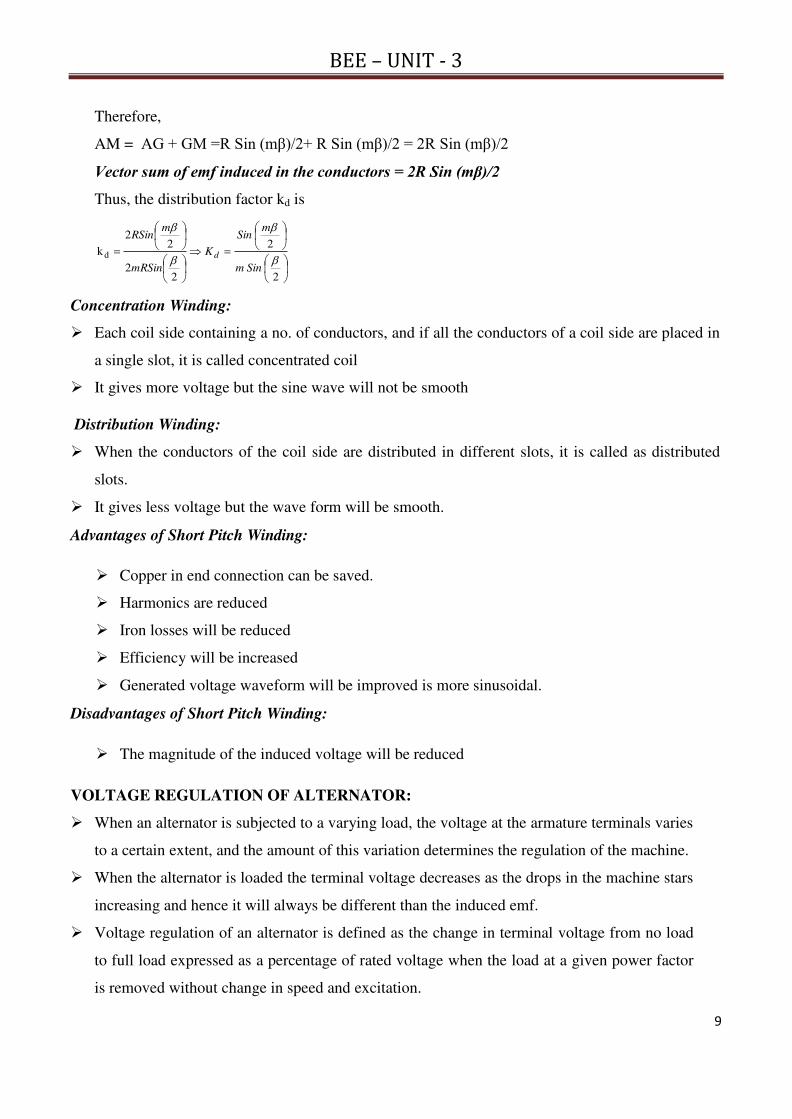
BEE – UNIT - 3
9
Therefore,
AM = AG + GM =R Sin (mβ)/2+ R Sin (mβ)/2 = 2R Sin (mβ)/2
Vector sum of emf induced in the conductors = 2R Sin (mβ)/2
Thus, the distribution factor kd is
2
2
22
22
kd
Sinm
mSin
K
mRSin
mRSin
d
Concentration Winding:
Each coil side containing a no. of conductors, and if all the conductors of a coil side are placed in
a single slot, it is called concentrated coil
It gives more voltage but the sine wave will not be smooth
Distribution Winding:
When the conductors of the coil side are distributed in different slots, it is called as distributed
slots.
It gives less voltage but the wave form will be smooth.
Advantages of Short Pitch Winding:
Copper in end connection can be saved.
Harmonics are reduced
Iron losses will be reduced
Efficiency will be increased
Generated voltage waveform will be improved is more sinusoidal.
Disadvantages of Short Pitch Winding:
The magnitude of the induced voltage will be reduced
VOLTAGE REGULATION OF ALTERNATOR:
When an alternator is subjected to a varying load, the voltage at the armature terminals varies
to a certain extent, and the amount of this variation determines the regulation of the machine.
When the alternator is loaded the terminal voltage decreases as the drops in the machine stars
increasing and hence it will always be different than the induced emf.
Voltage regulation of an alternator is defined as the change in terminal voltage from no load
to full load expressed as a percentage of rated voltage when the load at a given power factor
is removed without change in speed and excitation.

BEE – UNIT - 3
10
(or)
The numerical value of the regulation is defined as the percentage rise in voltage when full
load at the specified power-factor is switched off with speed and field current remaining
unchanged expressed as a percentage of rated voltage.
Hence regulation can be expressed as
100Regulation %
ph
phph
V
VE
where Eph = induced emf per phase, Vph = rated terminal voltage per phase
EMF method (or) Synchronous impedance method:
This method is also known as synchronous impedance method.
Here the magnetic circuit is assumed to be unsaturated.
In this method the MMFs (fluxes) produced by rotor and stator are replaced by their equivalent
emf, and hence called emf method.
To predetermine the regulation by this method the following information is to be determined.
Open circuit characteristics of the alternator.
Short circuit characteristics of the alternator.
The voltage drop in an alternator is mainly due to the following reasons
1. Voltage drop due to armature winding resistance (Ia Ra)
2. Voltage drop due to armature winding leakage reactance (Ia XL)
3. Voltage drop due to armature reaction drop (Ia Xa)
The combination of 2 and 3 leads to the voltage drop due to armature winding leakage
reactance and armature reaction drop called as voltage drop due to synchronous reactance
(Xs)= Ia (XL+Xa) = Ia Xs
Combination of the drops due to Ra and Xs is known as voltage drop due to synchronous
impedance drop (Ia Zs)

BEE – UNIT - 3
11
Calculation of no load induced emf (E) from the terminal voltage (V)
The calculation of no load induced emf (E) from the terminal voltage (V) at rated load depends on the
nature of the load
For Lagging pf loads (inductive loads):
Let the known quantities are
V = Terminal voltage under rated load in Volts = OA
Ia = Rated armature current in Ampere
Ra = Armature resistance in ohms
Xs = synchronous reactance in ohms
E = No load induced emf in Volts = OC
From the KVL
saa jXRIVE
1. Draw the phasor diagram for the above KVL equation as shown in the figure with known
quantities
2. Take the reference phasor as OA = terminal voltage (V), since the load is inductive the current is
lagging to phasor OA by its load phase angle Φ lag.
3. Add IaRa drop = AB = FD to the terminal voltage V which is inpase to Ia
4. From point B add IaXs drop = BC which is leading to Ia by 900
5. Join points O and C i.e OC = E no-load induced emf
6. From ΔODC
aa
22 RIVcosFDOFOD DCODOC
saXIVsinBCDB DC
PF LAGGING------ XIVsinRIVcos2
sa
2
aa E
For Unity pf loads (resistive loads):
Since phase angle Φ = 0 degrees, the power factor cosΦ = 1
Then from ΔOBC
aa
22 RIVABOAOB BCOBOC
saXI BC
LOADS UPF----- XIRI2
sa
2
aa VE

BEE – UNIT - 3
12
For Leading pf loads (capacitive loads):
From ΔODC
aa
22 RIVcosFDOFOD DCODOC
saXIVsinBCDBDC
PFLEADING ------ XIVsinRIVcos2
sa
2
aa E
Open circuit characteristics on the alternator
1. The alternator is made to run at no-load or with the terminals kept opened.
2. The alternator is operated with constant speed at rated value.
3. A voltmeter is connected in parallel to the opened terminals.
4. A variable excitation is applied to the field winding in a step wise.
5. As the voltage induced in the alternator is directly proportional to the excitation.
6. Tabulate the values of field currents and the corresponding induced voltages up to 125% of
rated voltage.
7. Plot the graph between field current and open circuit voltage as shown in the below figure.
8. The open circuit characteristic is linear at the lower portion and is almost constant at the rated
excitation values.
Short circuit characteristics on the alternator
1. The alternator is made to run with the terminals shorted
2. The alternator is operated with constant speed at rated value
3. An ammeter is connected in series to the shorted terminals.
4. An excitation is applied to the field winding such a way that rated short circuited current
passes through it
5. As the current in the alternator under short circuit is directly proportional to the excitation, so
the plot of the Short circuit characteristic is a straight line passing through the origin.

BEE – UNIT - 3
13
Calculation of synchronous impedance of an alternator:
1. From the plots of OCC and SC,
Voc and Isc corresponding to the field current of If1 is
identified and the ratio of these Voc to Isc is defined as
the synchronous impedance Zs.
f1sc
f1ocs
I sameat I
Iat VZ
2. From the obtained synchronous impedance Zs, the
synchronous reactance Xs is calculated with the
known value of armature resistance Ra
X Z 22
s
22
s assa RZXR
3. Due to this synchronous impedance Zs there is a fall in terminal voltage when the load on the
alternator is increased from no load to rated load.
4. The difference of the voltage from no-load (E) to rated load (V) expressed in terms of rated
voltage (V) is known as voltage regulation
100V
V - E n Regulatio%
Where
E = No-load voltage in Volts
V = Rated load Voltage in Volts
5. The no-load voltage E is calculated using the above defined formula after obtaining the value
of Xs from point no.2
6. The formula for no-load voltage E is
XIVsinRIVcos2
sa
2
aa E
(+) Sign is for lagging power factor and (-) Sign is for leading power factor.
Since the regulation is estimated from the calculation of EMF value hence method is known as EMF
method or from the calculation of synchronous impedance value hence called synchronous impedance
method
Synchronous Motors: Construction of three phase synchronous motor - operating principle
–equivalent circuit of synchronous motor.
INTRODUCTION
It may be recalled that a d.c. generator can be run as a d.c. motor. In like manner, an alternator
may operate as a motor by connecting its armature winding to a 3-phase supply. It is then called a
synchronous motor.
As the name implies, the synchronous motor runs at synchronous speed (Ns = 120f/P) i.e., in
synchronism with the revolving field produced by the 3-phase supply.
The speed of rotation is, therefore, tied to the frequency of the source. Since the frequency is
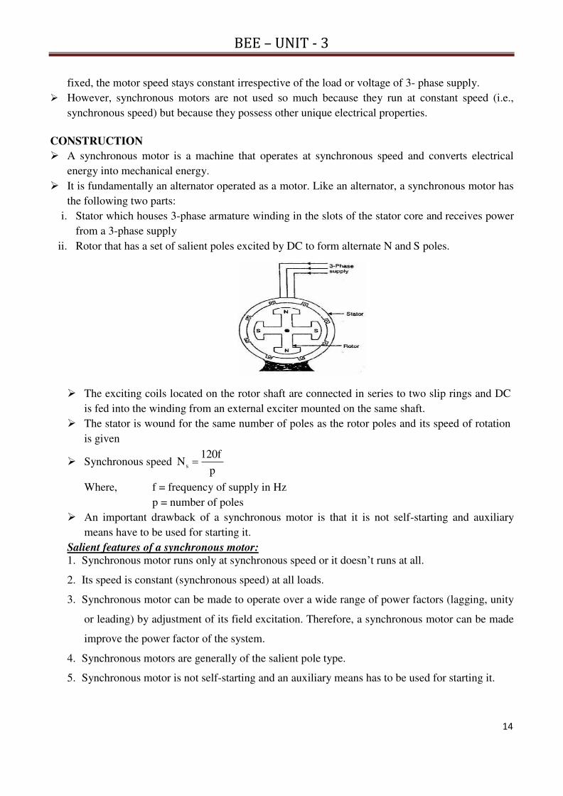
BEE – UNIT - 3
14
fixed, the motor speed stays constant irrespective of the load or voltage of 3- phase supply.
However, synchronous motors are not used so much because they run at constant speed (i.e.,
synchronous speed) but because they possess other unique electrical properties.
CONSTRUCTION
A synchronous motor is a machine that operates at synchronous speed and converts electrical
energy into mechanical energy.
It is fundamentally an alternator operated as a motor. Like an alternator, a synchronous motor has
the following two parts:
i. Stator which houses 3-phase armature winding in the slots of the stator core and receives power
from a 3-phase supply
ii. Rotor that has a set of salient poles excited by DC to form alternate N and S poles.
The exciting coils located on the rotor shaft are connected in series to two slip rings and DC
is fed into the winding from an external exciter mounted on the same shaft.
The stator is wound for the same number of poles as the rotor poles and its speed of rotation
is given
Synchronous speed p
120fNs
Where, f = frequency of supply in Hz
p = number of poles
An important drawback of a synchronous motor is that it is not self-starting and auxiliary
means have to be used for starting it.
Salient features of a synchronous motor:
1. Synchronous motor runs only at synchronous speed or it doesn’t runs at all.
2. Its speed is constant (synchronous speed) at all loads.
3. Synchronous motor can be made to operate over a wide range of power factors (lagging, unity
or leading) by adjustment of its field excitation. Therefore, a synchronous motor can be made
improve the power factor of the system.
4. Synchronous motors are generally of the salient pole type.
5. Synchronous motor is not self-starting and an auxiliary means has to be used for starting it.

BEE – UNIT - 3
15
OPERATING PRINCIPLE
The fact that a synchronous motor has no starting torque can be easily explained.
Consider a 3-phase synchronous motor having two rotor poles NR and SR. Then the stator will
also be wound for two poles NS and SS.
The motor has direct voltage applied to the rotor winding and a 3-phase voltage applied to the
stator winding.
The stator winding produces a rotating field which revolves round the stator at synchronous
speed Ns(= 120 f/P).
The direct (or zero frequency) current sets up a two-pole field which is stationary so long as
the rotor is not running.
Thus, we have a situation in which there exists a pair of revolving armature poles (i.e., NS -
SS) and a pair of stationary rotor poles (i.e., NR - SR).
Suppose at any instant, the stator poles are at positions A and B as shown in figure below, It is
clear that poles NS and NR repel each other and so do the poles SS and SR.
Therefore, the rotor tends to move in the anticlockwise direction. After a period of half-cycle
(or ½ f = 1/100 second), the polarities of the stator poles are reversed but the polarities of the
rotor poles remain the same as shown in below figure Now SS and NR attract each other and
so do NS and SR.
Therefore, the rotor tends to move in the clockwise direction. Since the stator poles change
their polarities rapidly, they tend to pull the rotor first in one direction and then after a period
of half-cycle in the other. Due to high inertia of the rotor, the motor fails to start.
Hence, the synchronous motor has no self-starting torque i.e., a synchronous motor cannot
start by itself.
Making Synchronous Motor Self-Starting
A synchronous motor cannot start by itself. In order to make the motor self-starting, a squirrel
cage winding (also called damper winding) is provided on the rotor.

BEE – UNIT - 3
16
The damper winding consists of copper bars embedded in the
pole faces of the salient poles of the rotor as shown in Fig.
The bars are short-circuited at the ends to form in effect a partial
squirrel cage winding. The damper winding serves to start the
motor.
To start with, 3-phase supply is given to the stator winding while
the rotor field winding is left unenergized. The rotating stator
field induces currents in the damper or squirrel cage winding and
the motor starts as an induction motor.
As the motor approaches the synchronous speed, the rotor is excited with direct current. Now
the resulting poles on the rotor face poles of opposite polarity on the stator and a strong
magnetic attraction is set up between them. The rotor poles lock in with the poles of rotating
flux. Consequently, the rotor revolves at the same speed as the stator field i.e., at synchronous
speed.
Because the bars of squirrel cage portion of the rotor now rotate at the same speed as the
rotating stator field, these bars do not cut any flux and,
Therefore, have no induced currents in them. Hence squirrel cage portion of the rotor is, in
effect, removed from the operation of the motor.
It may be emphasized here that due to magnetic interlocking between the stator and rotor
poles, a synchronous motor can only run at synchronous speed. At any other speed, this
magnetic interlocking (i.e., rotor poles facing opposite polarity stator poles) ceases and the
average torque becomes zero. Consequently, the motor comes to a halt with a severe
disturbance on the line.
Note: It is important to excite the rotor with direct current at the right moment.
For example, if the d.c. excitation is applied when N-pole of the stator faces N pole of the
rotor, the resulting magnetic repulsion will produce a violent mechanical shock. The motor
will immediately slow down and the circuit breakers will trip. In practice, starters for
synchronous motors are designed to detect the precise moment when excitation should be
applied.
EQUIVALENT CIRCUIT OF SYNCHRONOUS MOTOR
Unlike the induction motor, the synchronous motor is connected to two electrical systems;
i. DC source to the rotor terminals
ii. AC source to the stator terminals
1. Under normal conditions of synchronous motor operation, no voltage is induced in the rotor by
the stator field because the rotor winding is rotating at the same speed as the stator field.
2. In the stator winding, two effects are to be considered, the effect of stator field on the stator
winding and the effect of the rotor field cutting the stator conductors at synchronous speed.
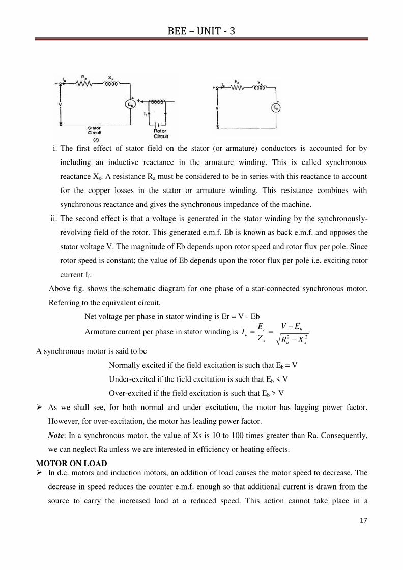
BEE – UNIT - 3
17
i. The first effect of stator field on the stator (or armature) conductors is accounted for by
including an inductive reactance in the armature winding. This is called synchronous
reactance Xs. A resistance Ra must be considered to be in series with this reactance to account
for the copper losses in the stator or armature winding. This resistance combines with
synchronous reactance and gives the synchronous impedance of the machine.
ii. The second effect is that a voltage is generated in the stator winding by the synchronously-
revolving field of the rotor. This generated e.m.f. Eb is known as back e.m.f. and opposes the
stator voltage V. The magnitude of Eb depends upon rotor speed and rotor flux per pole. Since
rotor speed is constant; the value of Eb depends upon the rotor flux per pole i.e. exciting rotor
current If.
Above fig. shows the schematic diagram for one phase of a star-connected synchronous motor.
Referring to the equivalent circuit,
Net voltage per phase in stator winding is Er = V - Eb
Armature current per phase in stator winding is 22
sa
b
s
ra
XR
EV
Z
EI
A synchronous motor is said to be
Normally excited if the field excitation is such that Eb = V
Under-excited if the field excitation is such that Eb < V
Over-excited if the field excitation is such that Eb > V
As we shall see, for both normal and under excitation, the motor has lagging power factor.
However, for over-excitation, the motor has leading power factor.
Note: In a synchronous motor, the value of Xs is 10 to 100 times greater than Ra. Consequently,
we can neglect Ra unless we are interested in efficiency or heating effects.
MOTOR ON LOAD
In d.c. motors and induction motors, an addition of load causes the motor speed to decrease. The
decrease in speed reduces the counter e.m.f. enough so that additional current is drawn from the
source to carry the increased load at a reduced speed. This action cannot take place in a

BEE – UNIT - 3
18
synchronous motor because it runs at a constant speed (i.e., synchronous speed = 3000 rpm) at all
loads.
Whereas when the mechanical load on synchronous motor is increased the rotor poles fall slightly
behind the stator poles while continuing to run at 2990 r.p.m synchronous speed. The angular
displacement between stator and rotor poles (called torque angle α) causes the phase of back
e.m.f. Eb to change w.r.t. supply voltage V. This increases the net e.m.f. Er in the stator winding.
Consequently, stator current Ia ( = Er/Zs) increases to carry the load.
The following points may be noted in synchronous motor operation:
1. A synchronous motor runs at synchronous speed at all loads. It meets the increased load not by
a decrease in speed but by the relative shift between stator and rotor poles i.e., by the
adjustment of torque angle α.
2. If the load on the motor increases, the torque angle α also increases (i.e., rotor poles lag behind
the stator poles by a greater angle) but the motor continues to run at synchronous speed. The
increase in torque angle α causes a greater phase shift of back e.m.f. Eb w.r.t. supply voltage V.
This increases the net voltage Er in the stator winding. Consequently, armature current Ia (=
Er/Zs) increases to meet the load demand.
3. If the load on the motor decreases, the torque angle a also decreases. This causes a smaller
phase shift of Eb w.r.t. V. Consequently, the net voltage Er in the stator winding decreases and
so does the armature current Ia (=Er/Zs).
Pull-Out Torque
There is a limit to the mechanical load that can be applied to a synchronous motor. As the load
increases, the torque angle α also increases so that a stage is reached when the rotor is pulled
out of synchronism and the motor comes to a standstill.
This load torque at which the motor pulls out of synchronism is called pull—out or breakdown
torque. Its value varies from 1.5 to 3.5 times the full— load torque.

BEE – UNIT - 3
19
SYNCHRONOUS CONDENSER
A synchronous motor takes a leading current when over-excited and, therefore, behaves as a
capacitor.
An over-excited synchronous motor running on no-load in known as synchronous condenser.
When such a machine is connected in parallel with induction motors or other devices that operate at
low lagging power factor, the leading kVAR supplied by the synchronous condenser partly
neutralizes the lagging reactive kVAR of the loads. Consequently, the power factor of the system is
improved.
Fig. below shows the power factor improvement by synchronous condenser method. The 3 - Φ load
takes current IL at low lagging power factor cos ΦL. The synchronous condenser takes a current Im
which leads the voltage by an angle Φm. The resultant current I is the vector sum of Im and IL and
lags behind the voltage by an angle Φ. It is clear that Φ is less than ΦL so that cos Φ is greater than
cos ΦL. Thus the power factor is increased from cos ΦL to cos Φ. Synchronous condensers are
generally used at major bulk supply substations for power factor improvement
Advantages 1. By varying the field excitation, the magnitude of current drawn by the motor can be changed
by any amount. This helps in achieving step less control of power factor. 2. The motor windings have high thermal stability to short circuit currents. 3. The faults can be removed easily.
Disadvantages 1. There are considerable losses in the motor. 2. The maintenance cost is high. 3. It produces noise. 4. Except in sizes above 500 RVA, the cost is greater than that of static
capacitors of the same rating. 5. As a synchronous motor has no self-starting torque, then-fore, an auxiliary
equipment has to be provided for this purpose. Applications of Synchronous Motors
1. Synchronous motors are particularly attractive for low speeds (< 300 r.p.m.) because the power factor can always be adjusted to unity and efficiency is high.
2. Overexcited synchronous motors can be used to improve the power factor of a plant while carrying their rated loads.
3. They are used to improve the voltage regulation of transmission lines.

1
BEE – UNIT -4
Unit – 4 (BEE) R -19 Regulations – I ECE II Semester
Induction Machine: Principle of operation and construction of three-phase induction
motors –slip ring and squirrel cage motors – slip-torque characteristics – efficiency
calculation – starting methods Brake test on 3-Phase Induction Motor.
CONSTRUCTION OF 3-PHASE INDUCTION MOTOR
The 3-Phase induction motor consists of mainly two parts namely stator and rotor
Stator: The stator consists of
Stator frame: The stator frame is made of cast iron and consists of
cooling fins
It gives the support and protects other parts of the motor
Stator core: The stator core is made of with laminated high grade alloy steel
stampings and slotted on the inner periphery and these stampings are insulated.
Stator winding: The stator winding is placed in the stator core, which is connected
either in star or delta
Squirrel cage Rotor:
1. The rotor core is a cylindrical one built from a high
grade alloy steel laminations.
2. It consists of rotor slots in parallel to the shaft axis on
the outer periphery.
3. In general the slots are not parallel to the shaft but skewed with some angle to the
shat
4. The purpose of the skewing is to prevent interlocking and to reduce the humming
noise
5. The rotor copper bars are placed in the rotor slots and the bars are short circuited
with end rings.
6. In Cage rotor type there is no chance of adding the external resistance to the rotor
to improve the torque developed at starting.
Slip ring rotor (or) Phase Wound rotor:

2
BEE – UNIT -4
1. The rotor core is a cylindrical one built from a high grade alloy steel laminations.
2. It consists of rotor slots on the outer periphery where the star connected winding is
done.
3. The star connected rotor winding is done for the same poles as that of the stator
winding
4. The ends of the star connected rotor winding are connected to the three slip rings
placed on the shaft.
5. The carbon brushes are mounted on the slip rings, through which an external resistance
is added to the rotor.
6. The advantage of the Wound rotor is the starting torque is improved by adding the
external resistance to the rotor using slip rings.
Rotating Magnetic Field
1. The induction motor rotates due to the rotating magnetic field in 3 phase
induction motor, which is produced by the stator winding in the air gap between in the stator and the rotor.
2. The stator has a three phase stationary winding which can be either star connected or delta connected.
3. Whenever the AC supply is connected to the stator windings, line currents IR, IY, and IB start flowing.
4. These line currents have phase difference of 120o with respect to each other. 5. Due to each line current, a sinusoidal flux is produced in the air gap. 6. These fluxes have the same frequency as that of the line currents, and they also
have the same phase difference of 120o with respect to each other. Let the flux produced by the line currents IR, IB, IY be φR, φB, φY respectively.
Mathematically, they are represented as follows: φR = φm sin ωt = φm sin θ φY = φm sin (ωt – 120o) = φm sin (θ – 120o) φB = φm sin (ωt – 240o) = φm sin (θ – 240o)
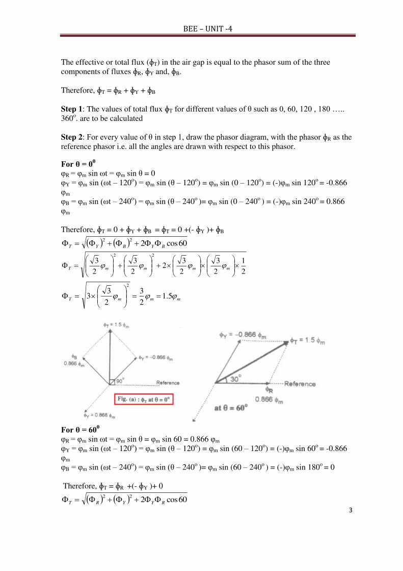
3
BEE – UNIT -4
The effective or total flux (ɸT) in the air gap is equal to the phasor sum of the three components of fluxes ɸR, ɸY and, ɸB. Therefore, ɸT = ɸR + ɸY + ɸB
Step 1: The values of total flux ɸT for different values of θ such as 0, 60, 120 , 180 ….. 360o. are to be calculated Step 2: For every value of θ in step 1, draw the phasor diagram, with the phasor ɸR as the reference phasor i.e. all the angles are drawn with respect to this phasor.
For θ = 00
φR = φm sin ωt = φm sin θ = 0 φY = φm sin (ωt – 120o) = φm sin (θ – 120o) = φm sin (0 – 120o) = (-)φm sin 120o = -0.866 φm φB = φm sin (ωt – 240o) = φm sin (θ – 240o
)= φm sin (0 – 240o ) = (-)φm sin 240o = 0.866
φm Therefore, ɸT = 0 + ɸY + ɸB = ɸT = 0 +(- ɸY )+ ɸB
60cos222
BYBYT
2
1
2
3
2
32
2
3
2
322
mmmmT
mmmT 5.12
3
2
33
2
For θ = 600
φR = φm sin ωt = φm sin θ = φm sin 60 = 0.866 φm φY = φm sin (ωt – 120o) = φm sin (θ – 120o) = φm sin (60 – 120o) = (-)φm sin 60o = -0.866 φm φB = φm sin (ωt – 240o) = φm sin (θ – 240o
)= φm sin (60 – 240o ) = (-)φm sin 180o = 0
Therefore, ɸT = ɸR +(- ɸY )+ 0
60cos222
RYYRT

4
BEE – UNIT -4
2
1
2
3
2
32
2
3
2
322
mmmmT
mmmT 5.12
3
2
33
2
For θ = 1200
φR = φm sin ωt = φm sin θ = φm sin 120 = 0.866 φm φY = φm sin (ωt – 120o) = φm sin (120 – 120o) = (-)φm sin 0o = 0 φB = φm sin (ωt – 240o) = φm sin (120 – 240o
) = (-)φm sin 120o = -0.866 φm Therefore, ɸT = ɸR +0+ (- ɸB )
60cos222
BRBRT
2
1
2
3
2
32
2
3
2
322
mmmmT
mmmT 5.12
3
2
33
2
For θ = 180
0
φR = φm sin ωt = φm sin θ = φm sin 180 = 0 φY = φm sin (ωt – 120o) = φm sin (180 – 120o) = φm sin 60o = 0.866 φm φB = φm sin (ωt – 240o) = φm sin (180 – 240o
) = (-)φm sin 60o = -0.866 φm Therefore, ɸT = 0 + ɸY + (- ɸB )
60cos222
BYBYT
2
1
2
3
2
32
2
3
2
322
mmmmT
mmmT 5.12
3
2
33
2
For θ = 2400
φR = φm sin ωt = φm sin θ = φm sin 240 = -0.866 φm φY = φm sin (ωt – 120o) = φm sin (240 – 120o) = φm sin 120o = 0.866 φm φB = φm sin (ωt – 240o) = φm sin (240 – 240o
) = φm sin 0o = 0 Therefore, ɸT = (- ɸR ) + ɸY + 0
60cos222
YRYRT
2
1
2
3
2
32
2
3
2
322
mmmmT
mmmT 5.12
3
2
33
2

5
BEE – UNIT -4
For θ = 300
0
φR = φm sin ωt = φm sin θ = φm sin 300 = -0.866 φm φY = φm sin (ωt – 120o) = φm sin (300 – 120o) = φm sin 180o = 0 φB = φm sin (ωt – 240o) = φm sin (300 – 240o
) = φm sin 60o = 0.866 φm Therefore, ɸT = (- ɸR ) + ɸY + 0
60cos222
BRBRT
2
1
2
3
2
32
2
3
2
322
mmmmT
mmmT 5.12
3
2
33
2
For θ = 3600
φR = φm sin ωt = φm sin θ = φm sin 360 = 0 φY = φm sin (ωt – 120o) = φm sin (360 – 120o) = φm sin 240o = - 0.866 φm φB = φm sin (ωt – 240o) = φm sin (300 – 240o
) = φm sin 60o = 0.866 φm Therefore, ɸT =0 + (- ɸY ) + ɸB
60cos222
BYBYT
2
1
2
3
2
32
2
3
2
322
mmmmT
mmmT 5.12
3
2
33
2
In the similar way as shown in the phasor diagrams the resultant or total flux rotates 60
degrees for every instant and completes one cycle of rotation in the direction of phase
sequence of the supply.
Thus when a three phase supply is applied to the three phase winding connected either in
star or delta it produces a rotating magnetic field having
i. a constant magnitude of 1.5 times the Φm
ii. a constant speed of synchronous speed Ns=120f/P
iii. a direction equal to its phase sequence

6
BEE – UNIT -4
WORKING PRINCIPLE OF 3-PHASE INDUCTION MOTOR
1. The balanced three-phase winding of the stator is supplied with a balanced three-phase
voltage.
2. The current in the stator winding produces a rotating magnetic field, with constant
magnitude of 1.5Øm and rotates at synchronous speed of Ns=120f/P
3. The magnetic flux lines in the air gap cut both stator and rotor (being stationary, as the
motor speed is zero) conductors at the same speed.
4. The emfs in both stator and rotor conductors are induced at the same frequency, i.e. line
or supply frequency, with No. of poles for both stator and rotor windings (assuming
wound one) being same.
5. As the rotor winding is short-circuited at the slip-rings, current flows in the rotor
windings.
6. The electromagnetic torque in the motor is in the same direction as that of the rotating
magnetic field, due to the interaction between the rotating flux produced in the air gap by
the current in the stator winding, and the current in the rotor winding.
7. This is as per Lenz’s law, as the developed torque is in such direction that it will oppose
the cause, which results in the current flowing in the rotor winding.
8. As the rotor starts rotating in the same direction, as that of the rotating magnetic field due
to production of the torque as stated earlier, the relative velocity decreases, along with
lower values of induced emf and current in the rotor.
9. If the rotor speed is equal that of the rotating magnetic field, which is termed as
synchronous speed, and also in the same direction, the relative velocity is zero, which
causes both the induced emf and current in the rotor to be reduced to zero. Under this
condition, torque will not be produced.
10. So, for production of positive (motoring) torque, the rotor speed must always be lower
than the synchronous speed. The rotor speed is never equal to the synchronous speed in
an IM.
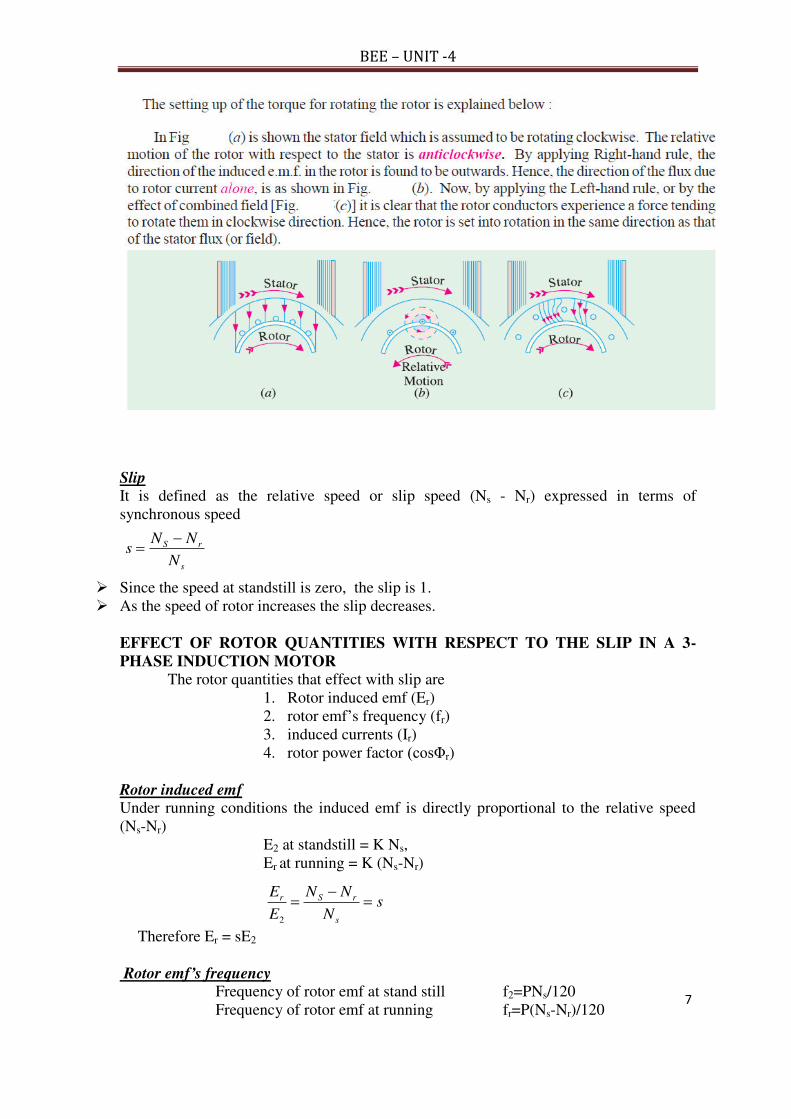
7
BEE – UNIT -4
sN
NN
E
E
s
rSr
2
s
rS
N
NNs
Slip
It is defined as the relative speed or slip speed (Ns - Nr) expressed in terms of synchronous speed
Since the speed at standstill is zero, the slip is 1. As the speed of rotor increases the slip decreases.
EFFECT OF ROTOR QUANTITIES WITH RESPECT TO THE SLIP IN A 3-
PHASE INDUCTION MOTOR
The rotor quantities that effect with slip are 1. Rotor induced emf (Er) 2. rotor emf’s frequency (fr) 3. induced currents (Ir) 4. rotor power factor (cosΦr)
Rotor induced emf Under running conditions the induced emf is directly proportional to the relative speed (Ns-Nr)
E2 at standstill = K Ns, Er at running = K (Ns-Nr)
Therefore Er = sE2
Rotor emf’s frequency Frequency of rotor emf at stand still f2=PNs/120 Frequency of rotor emf at running fr=P(Ns-Nr)/120

8
BEE – UNIT -4
sN
NN
f
f
s
rSr
2
2
2
22
2
2
xsr
sE
Z
EI
r
rr
2
2
22
2
22cosxsr
r
Z
r
r
r
sf
sf
f
f
Lf
Lf
X
X rrr 2
2
222
2
2 2
2
22
2
2
22
2
2
2
2
22 and sXRXRZXRZ rr
2
2
2
2
2
2
22
xr
E
Z
EI
2
2
2
2
2
2
22cos
xr
r
Z
r
Therefore fr = sf2 = sf
Rotor reactance
Rotor reactance at stand still X2=2ΠfL2 Rotor reactance at running Xr=2ΠfrL2
Therefore Xr = sX2
Rotor impedance
Rotor impedance at stand still Z2=R2+jX2 Rotor impedance at running Zr= R2+jXr
Rotor induced currents
The rotor current is defined as the ratio of the rotor emf to the rotor impedance. Rotor current at stand still is
Rotor current at running is
Rotor power factor
Power factor is defined as the ratio of the rotor resistance to the rotor impedance Rotor power factor at stand still is
Rotor power factor at running is
TORQUE EQUATION OF 3-Φ INDUCTION MOTOR
Torque at stand still The torque in the motor is directly proportional to the product of flux and active component of the rotor current
22 cos IT
Here the flux is directly proportional to the rotor induced emf E2 i.e 2E
The rotor current I2 and rotor power factor cosΦ2 are
2
22
2
22 cos and
Z
R
Z
EI

9
BEE – UNIT -4
2
2
2
2
2
2
2
2
2
22
XR
R
XR
EET
rpsin speed ssynchronou is here 2
3 where
2
2
2
2
2
2
2s
s
nn
kXR
REkT
Therefore, torque at standstill is 2
2
2
2
2
2
2
2
3
XR
RE
nT
s
From the above equation torque at stand still depends on rotor resistance (R2), so keeping this R2 as variable the condition for the maximum torque at standstill is
02
dR
dTst
Rewriting the stand still torque
sn
E
XR
RKT
23
K where 2
2
2
2
2
2
2
and 2
2
2
2
2
XR
RT
02 0
2 0 22
2
2
2
222
2
2
2
22
2
2
2
2
2
2
2
2
2
2
RRXRXR
RRXR
dR
XR
Rd
22
2
2
2
2
2
2
2
2
2
2 2 XRXRRXR
Therefore on adding the resistance to the rotor such that R2 = X2, the motor will develop
maximum torque at stand still.
The maximum torque at standstill is 22
3 T
2
2
3
2
2
2max
2
2
2
2
2
2
2
2max
X
E
nX
K
XX
XE
nT
ss
Torque at running condition
The torque in the motor is directly proportional to the product of flux and active component of the rotor current
rrIT cos
Here the flux is directly proportional to the rotor induced emf E2 i.e 2E
The rotor current Ir and rotor power factor cosΦr are
rr
rr
Z
R
Z
EI 2
rcos and
22
2
2
22
2
2
rr
r
XR
R
XR
EET
22
2
2
2
2
2
2
2
22
sXR
R
sXR
sEET
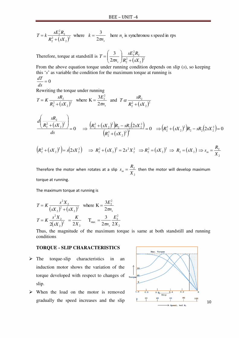
10
BEE – UNIT -4
rpsin speed ssynchronou is here
2
3 where
2
2
2
2
2
2
2s
s
nn
ksXR
RsEkT
Therefore, torque at standstill is 22
2
2
2
2
2
2
3
sXR
RsE
nT
s
From the above equation torque under running condition depends on slip (s), so keeping this ‘s’ as variable the condition for the maximum torque at running is
0ds
dT
Rewriting the torque under running
sn
E
sXR
sRKT
2
3K where
2
2
2
2
2
2
2
and
2
2
2
2
2
sXR
sRT
02 0
2 0 2
222
2
2
2
222
2
2
2
2
222
2
2
2
2
2
2
2
2
2
sXsRRsXR
sXR
sXsRRsXR
ds
sXR
sRd
2
222
2
2
2
2
2
2
22
2
2
2
2
2
2
2
2
2 2 2X
RssXRsXRXssXRsXssXR m
Therefore the motor when rotates at a slip
2
2
X
Rsm then the motor will develop maximum
torque at running.
The maximum torque at running is
sn
E
sXsX
XsKT
2
3K where
2
2
2
2
2
2
2
2
22
3 T
2
2
2
2
2max
2
2
2
2
2
X
E
nX
K
sX
XsKT
s
Thus, the magnitude of the maximum torque is same at both standstill and running conditions
TORQUE - SLIP CHARACTERISTICS
The torque-slip characteristics in an
induction motor shows the variation of the
torque developed with respect to changes of
slip.
When the load on the motor is removed
gradually the speed increases and the slip

11
BEE – UNIT -4
decreases
Considering, the speed at standstill Nr = 0 the slip s =1 and as the speed increases from 0
to Ns the slip s decreases from 1 to zero, any how the induction motor never rotates at Ns
so the slip never becomes 0
Let the torque in an induction motor is
22
2
2
22
2
2
2
2
2
2 T 2
3
sXR
sR
sXR
RsE
nT
s
For the smaller values of slips i.e 0 < s < sm , sX2 << R2 so neglecting sX2 , the torque in
this smaller range of slips is
sR
s
R
sR T T T
2
2
2
2
As the torque is directly proportional to slip s, Therefore as slip increases the torque
increases linearly and attains maximum torque when slip s = sm
For the larger values of slips i.e sm < s < 1, R2 << sX2 so neglecting R2 , the torque in this
larger range of slips is
1
T T 2
2
2
ssX
R
As the torque is inversely proportional to slip s, Therefore as slip increases the torque
decreases linearly and falls to the value of standstill torque Tst at s = 1
Salient points:
1. The maximum value of the torque is independent to the rotor resistance
2. The slip at which the maximum torque occurs (sm) depends on the rotor resistance
3. The motor develops maximum torque at starting itself by making sm =1 which is
possible when R2 = X2
POWER STAGES IN A 3-PHASE INDUCTION MOTOR
In a 3-Phase induction motor the power losses occurs in stator and rotor
Stator losses = Stator core loss + stator Cu loss
Rotor losses = Rotor Cu loss
Mechanical loss = Friction and windage loss

12
BEE – UNIT -4
Therefore,
Stator output power (P2) = Stator input power (P1) – stator losses
Rotor output power (Pm) = Rotor input power (P2) – rotor Cu loss
Motor output power (Psh) = Rotor output power (Pm) – Mechanical loss
Relationship between rotor input, rotor output and slip in a 3-Phase induction motor
The mechanical power in a motor is given by
TN
P rm
60
2 or T
NP s
60
22
Where Pm is the mechanical or gross output power and P2 is the air gap power or rotor
input. T = torque in the motor
TP rm ---- (1) and TP s2 ---- (2)
Eq (2) – Eq (1) = P2 - Pm = TTT rsrs ---- (3)
Divide Eq (3) with Eq (2)
s
ωωω
P
LossCu Rotor
P
PP
s
rs
22
m2
Rotor cu loss (RCL) = sP2 ----- (4)
Divide Eq (1) with Eq (2)
s1P
)1(P
P
PP
P
P
ωω
P
P
2
2
2
22
2
2
s
r
2
m
ssRCL
Pm = (1-s) P2 ---- (5)
Divide Eq (5) with Eq (4)
s
)1(
sP
)1(P
RCL
P
2
2m ss
RCL
s
)1(Pm
s ---- (6)
Finally from Eq’s (4), (5) & (6) P2 : RCL:: Pm = 1 : s :: (1-s)
Thus,
losscustatorlosscorestatorlosscurotorlossmechoutputmotor
outputmotor
inputmotor
outputmotor

13
BEE – UNIT -4
STARTING METHOD FOR INDUCTION MOTORS
A 3-phase induction motor is theoretically self starting. The stator of an induction motor
consists of 3-phase windings, which when connected to a 3-phase supply creates a
rotating magnetic field. This will link and cut the rotor conductors which in turn will
induce a current in the rotor conductors and create a rotor magnetic field. The magnetic
field created by the rotor will interact with the rotating magnetic field in the stator and
produce rotation.
Therefore, 3-phase induction motors employ a starting method not to provide a
starting torque at the rotor, but because of the following reasons;
1. Reduce heavy starting currents and prevent motor from overheating.
2. Provide overload and no-voltage protection.
There are many methods in use to start 3-phase induction motors. Some of
the common methods are;
Direct On-Line Starter (DOL)
Star-Delta Starter
Auto Transformer Starter
Rotor resistance Starter
Direct On-Line Starter (DOL)
1. The Direct On-Line (DOL) starter is the simplest and the
most inexpensive of all starting methods and is usually
used for squirrel cage induction motors.
2. It directly connects the contacts of the motor to the full
supply voltage. The starting current is very large, normally
6 to 8 times the rated current.
3. The starting torque is likely to be 0.75 to 2 times the full
load torque.
4. In order to avoid excessive voltage drops in the supply line
due to high starting currents, the DOL starter is used only
for motors with a rating of less than 5KW
5. There are safety mechanisms inside the DOL starter which
provides protection to the motor as well as the operator of
the motor.
6. The DOL starter consists of a coil operated contactor K1M controlled by start
and stop push buttons.

14
BEE – UNIT -4
7. On pressing the start push button S1, the contactor coil K1M is energized from
line L1. The three mains contacts (1-2), (3-4), and (5-6) in fig. are closed. The
motor is thus connected to the supply.
8. When the stop push button S2 is pressed, the supply through the contactor K1M
is disconnected. Since the K1M is de-energized, the main contacts (1- 2), (3-4),
and (5-6) are opened. The supply to motor is disconnected and the motor stops.
Star-Delta Starter
1. The star delta starting is a very common type of starter and extensively used,
compared to the other types of the starters. This method used reduced supply
voltage in starting. Figure shows the
connection of a 3phase induction motor
with a star – delta starter.
2. The method achieved low starting
current by first connecting the stator
winding in star configuration, and then
after the motor reaches a certain speed,
throw switch changes the winding
arrangements from star to delta
configuration.
3. By connecting the stator windings, first in star and then in delta, the line current
drawn by the motor at starting is reduced to one-third as compared to starting
current with the windings connected in delta.
4. At the time of starting when the stator windings are start connected, each stator
phase gets voltage 3
LVwhere VL is the line voltage.
5. Since the torque developed by an induction motor is proportional to the square
of the applied voltage, star- delta starting reduced the starting torque to one –
third that obtainable by direct delta starting.
a. K2M Main Contactor b. K3M Delta Contactor c. K1M Star Contactor d. F1 Thermal Overload Relay

15
BEE – UNIT -4
Auto Transformer Starter
1. The operation principle of auto transformer method is similar to the
star delta starter method.
2. The starting current is limited by (using a three phase auto
transformer) reduce the initial stator applied voltage.
3. The auto transformer starter is more expensive, more complicated in
operation and bulkier in construction when compared with the star –
delta starter method.
4. But an auto transformer starter is suitable for both star and delta
connected motors, and the starting current and torque can be adjusted
to a desired value by taking the correct tapping from the auto
transformer.
5. When the star delta method is considered, voltage can be adjusted only by
factor of 3
1 .
Rotor Resistance Starter
1. This method allows external resistance to be connected to the
rotor through slip rings and brushes.
2. Initially, the rotor resistance is set to maximum and is then
gradually decreased as the motor speed increases, until it
becomes zero.
3. The rotor impedance starting mechanism is usually very bulky
and expensive when compared with other methods.
4. It also has very high maintenance costs. Also, a considerable
amount of heat is generated through the resistors when current
runs through them.

16
BEE – UNIT -4
BRAKE TEST ON 3-PHASE INDUCTION MOTOR.
1. The brake test is a direct method of testing. It consists of applying a brake to a water – cooled pulley mounted on the shaft of the motor.
2. A rope is wound round the pulley and its two ends are attached to two spring balances S1 and S2.
3. The tension of the rope can be adjusted with the help of swivels. Then, the force acting tangentially on the pulley = (S1 – S2) Kgs.
4. If r is the pulley radius, the torque at the pulley, Tsh = (S1 – S2) r kg m. 5. If “ω” is the angular velocity of the motor. ω = 2N/60, Where N is the speed in
rpm. 6. Motor output Pout= 9.81 x 2N (s1 – s2) r watts. 7. The motor input can be measured directly from the wattmeter’s by summing w1
and w2 readings 8. Thus, the efficiency is calculated by taking the ratio of the motor output to the
motor input.

1
BEE – UNIT -5
Unit – 5 (BEE) R -19 Regulations – I ECE II Semester
Special Machines: Principle of operation and construction - single phase induction motor -
shaded pole motors – capacitor motors and AC servomotor.
SINGLE PHASE MOTORS
As the name suggests, these motors are used on single – phase supply. Single phase motors are
the most common type of electric motors, which finds wide domestic, commercial and
industrial applications.
Single phase motors are small size motors of fraction – kilowatt ratings. Domestic applications
like fans, hair driers, washing machines, mixers, refrigerators, food processors and other
kitchen equipment employ these motors.
These motors also find applications in air – conditioning fans, blower’s office machinery etc.
Single phase motors may be classified into the following basic types:
1. Single phase induction motors
2. AC. Series motor (universal motor)
3. Repulsion motors
4. Synchronous motor
Single Phase Induction Motor
A single phase induction motor is very similar to 3 – phase squirrel cage induction motor. It
has a squirrel – cage rotor identical to a 3 - phase squirrel cage motor and a single – phase
winding on the stator. Unlike 3 – phase induction motor, a single phase induction motor is not
self starting but requires some starting means.
Figure (1) shows 1 – phase induction motor having squirrel cage rotor and single phase
distributed stator winding.
Fig. (1) Single – phase induction motor
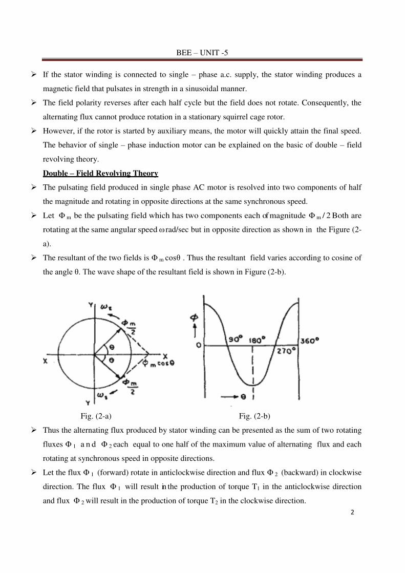
2
BEE – UNIT -5
If the stator winding is connected to single – phase a.c. supply, the stator winding produces a
magnetic field that pulsates in strength in a sinusoidal manner.
The field polarity reverses after each half cycle but the field does not rotate. Consequently, the
alternating flux cannot produce rotation in a stationary squirrel cage rotor.
However, if the rotor is started by auxiliary means, the motor will quickly attain the final speed.
The behavior of single – phase induction motor can be explained on the basic of double – field
revolving theory.
Double – Field Revolving Theory
The pulsating field produced in single phase AC motor is resolved into two components of half
the magnitude and rotating in opposite directions at the same synchronous speed.
Let Φ m be the pulsating field which has two components each of magnitude Φ m / 2 Both are
rotating at the same angular speed ω rad/sec but in opposite direction as shown in the Figure (2-
a).
The resultant of the two fields is Φ m cosθ . Thus the resultant field varies according to cosine of
the angle θ. The wave shape of the resultant field is shown in Figure (2-b).
Fig. (2-a) Fig. (2-b)
Thus the alternating flux produced by stator winding can be presented as the sum of two rotating
fluxes Φ 1 a n d Φ 2 each equal to one half of the maximum value of alternating flux and each
rotating at synchronous speed in opposite directions.
Let the flux Φ 1 (forward) rotate in anticlockwise direction and flux Φ 2 (backward) in clockwise
direction. The flux Φ 1 will result in the production of torque T1 in the anticlockwise direction
and flux Φ 2 will result in the production of torque T2 in the clockwise direction.

3
BEE – UNIT -5
At standstill, these two torques are equal and opposite and the net torque developed is zero.
Therefore, single – phase induction motor is not self – starting. This fact is illustrated in fig. (3)
Fig. (3) Torque – slip characteristic of 1- phase induction motor
Rotor Running
Assume that the rotor is started by spinning the rotor or by using auxiliary circuit, in say
clockwise direction.
The flux rotating in the clockwise direction is the forward rotating flux Φ f and that in the
other direction is the backward rotating flux Φ b .
The slip with respect to the forward flux will be s
sf
N
NNs
Where
Ns = synchronous speed
N = speed of rotor in the direction of forward flux
The rotor rotates opposite to the rotation of the backward flux. Therefore, the slip w.r.t the
backward flux will be
s
N
NN
N
N
N
NNN
N
NN
N
NNs
s
s
s
s
s
ss
s
s
s
sb
2
22)(
Thus for forward rotating flux, slip is s (less than unity) and for backward rotating
flux, the slip is 2-s (greater than unity) since for usual rotor resistance/reactance
ratios, the torque at slips of less than unity are greater than those at slips of more than
unity, the resultant torque will be in the direction of the rotation of the forward flux.
Thus if the motor is once started, it will develop net torque in the direction in which
it has been started and will function as a motor.

4
BEE – UNIT -5
Starting of Single Phase Induction Motors
The single phases induction motors are classified based on the method of starting method
and in fact are known by the same name descriptive of the method.
1. Split – phase Induction Motor
The stator of a split – phase induction motor has two windings,
1. Main winding
2. Auxiliary winding.
These windings are displaced in space by 90 electric degrees as shown in figure (4-a).
Fig.(4-a) split phase I.M.
The auxiliary winding is made of thin wire so that it has a high R/X ratio as compared to the
main winding which has thick super enamel copper wire.
When the two stator windings are energized from a single – phase supply, the current Im
and Ia in the main winding and auxiliary winding lag behind the supply voltage V, and Ia
leading the current Im as shown in figure (4-b).
Fig.(4-b) Phasor diagram at starting

5
BEE – UNIT -5
This means the current through auxiliary winding reaches maximum value first and the mmf
or flux due to Ia lies along the axis of the auxiliary winding and after some time the current Im
reaches maximum value and the mmf due to Im lies along the main winding axis.
Thus the motor becomes a 2 – phase unbalanced motor. Because of these two fields a starting
torque is developed and the motor becomes a self starting motor.
After the motor starts, the auxiliary winding is disconnected usually by means of centrifugal
switch that operates at about 75% of synchronous speed. Finally the motor runs because of
the main winding.
Since this being single phase some level of humming noise is always associated with the
motor during running. The power rating of such motors generally lies between 60- 250W.
The typical torque – speed characteristic is shown in fig (4-c).
Characteristics
Due to their low cost, split – phase induction motors are most popular single – phase
motors in the market
Since the starting winding is made of thin wire, the current density is high and the
winding heats up quickly. If the starting period exceeds 5 seconds, the winding may burn
out unless the motor is protected by built – in thermal relay. This motor is, therefore,
suitable where starting periods are not frequent.

6
BEE – UNIT -5
2. Capacitor – Start Motor
Capacitors are used to improve the starting and running performance of the single phase
inductions motors.
The capacitor – start motor is identical to a split – phase motor except that the starting
winding has as many turns as the main winding.
Moreover, a capacitor C is connected in series with the starting winding as shown in fig (5-a).
Fig.(5-a) Capacitor Start Motor
The value of capacitor is so chosen that Ia leads Im by about 90o (Fig.5-b) so that the starting
torque is maximum for certain values of Ia and Im.
Again, the starting winding is opened by the centrifugal switch when the motor attains about
75% of synchronous speed.
The motor then operates as a single – phase induction motor and continues to accelerate till it
reaches the normal speed.

7
BEE – UNIT -5
Fig. (5-c)
The typical torque – speed characteristic is shown in fig (5-c).
Characteristics
Although starting characteristics of a capacitor – start motor are better than those of a split –
phase motor, both machines possess the same running characteristics because the main windings
are identical.
The phase angle between the two currents is about 90 compared to about 25o in a split – phase
motor. Consequently, for the same starting torque, the current in the starting winding is only
about half that in a split – phase motor.
Therefore, the starting winding of a capacitor start motor heats up less quickly and is well suited
to applications involving either frequent or prolonged starting periods.
Capacitor – start motors are used where high starting torque is required and where high starting
period may be long e.g. to drive:
a) Compressors b) large fans c) pumps d)high inertia loads
The power rating of such motors lies between 120W and 0.75 kW.

8
BEE – UNIT -5
3. Permanent – Split Capacitor Motor
In this motor, as shown in fig.(6-a), the capacitor that is connected in series with the
auxiliary winding is not cut out after starting and is left in the circuit all the time.
This simplifies the construction and decreases the cost because the centrifugal switch is not
needed.
The power factor, torque pulsation, and efficiency are also improved because the motor runs as
a two – phase motor. The motor will run more quietly.
The capacitor value is of the order of 20 – 50F and because it operates continuously, it is
an ac paper oil type.
The capacitor is compromise between the best starting and running value and therefore
starting torque is sacrificed. The typical torque – speed characteristic is shown in fig (6-b).
Fig.(6-a) Permanent – Split Capacitor Motor
Fig.(6-b) torque – speed characteristic
Characteristic
These motor are used where the required starting torque is low such as air – moving equipment
i.e. fans, blowers and voltage regulators and also oil burners where quite operation is
particularly desirable.
4. Capacitor - Start Capacitor - Run
Two capacitor, one for starting and one for running, can be used, as shown in fig.(7-a).
Fig. (7-a) Capacitor - Start Capacitor – Run motor
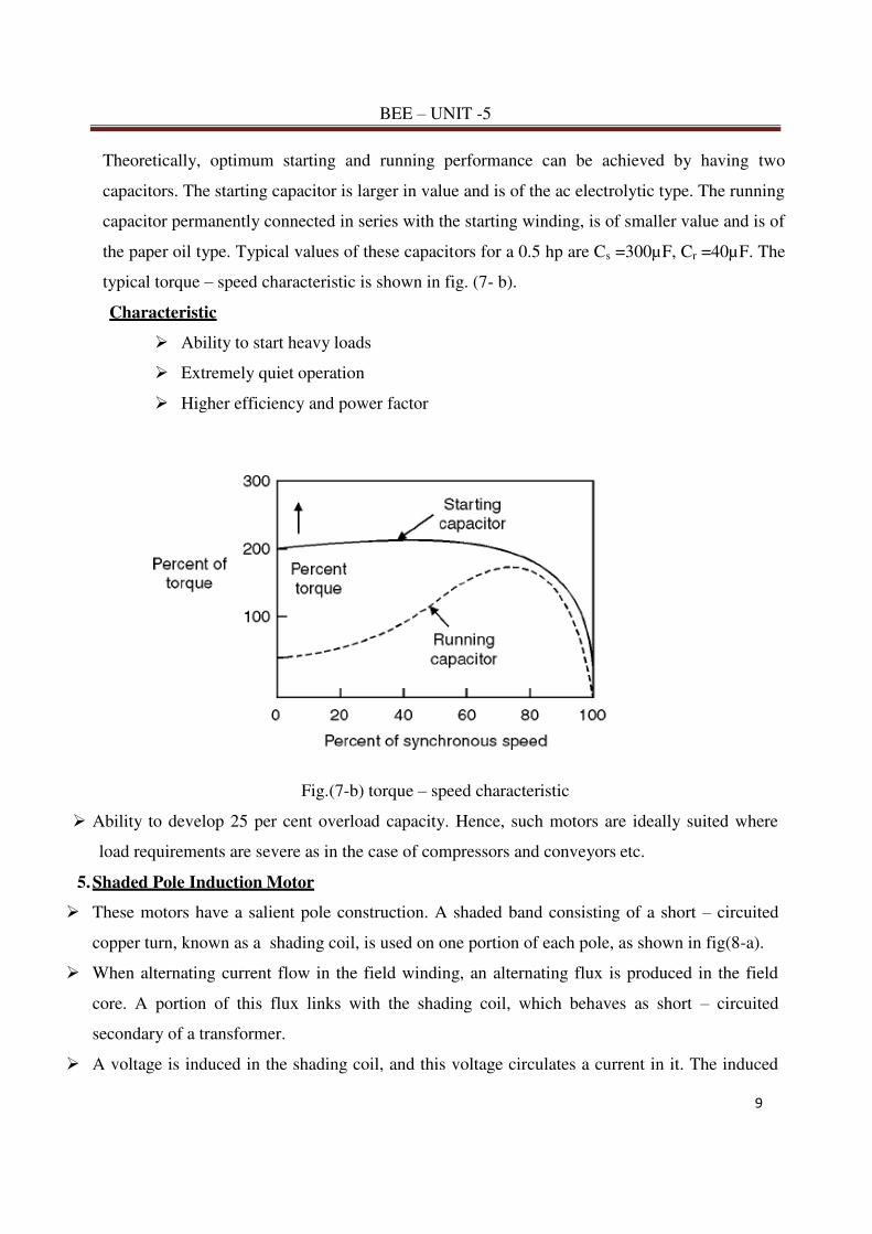
9
BEE – UNIT -5
Theoretically, optimum starting and running performance can be achieved by having two
capacitors. The starting capacitor is larger in value and is of the ac electrolytic type. The running
capacitor permanently connected in series with the starting winding, is of smaller value and is of
the paper oil type. Typical values of these capacitors for a 0.5 hp are Cs =300µF, Cr =40µF. The
typical torque – speed characteristic is shown in fig. (7- b).
Characteristic
Ability to start heavy loads
Extremely quiet operation
Higher efficiency and power factor
Fig.(7-b) torque – speed characteristic
Ability to develop 25 per cent overload capacity. Hence, such motors are ideally suited where
load requirements are severe as in the case of compressors and conveyors etc.
5. Shaded Pole Induction Motor
These motors have a salient pole construction. A shaded band consisting of a short – circuited
copper turn, known as a shading coil, is used on one portion of each pole, as shown in fig(8-a).
When alternating current flow in the field winding, an alternating flux is produced in the field
core. A portion of this flux links with the shading coil, which behaves as short – circuited
secondary of a transformer.
A voltage is induced in the shading coil, and this voltage circulates a current in it. The induced

10
BEE – UNIT -5
current produces a flux called the induced flux which opposes the main core flux.
Fig (8-a) Shaded Pole Induction Motor
The shading coil, thus, causes the flux in the shaded portion to lag behind the flux in the
unshaded portion of the pole.
At the same time, the main flux and the shaded pole flux are displaced in space. This
displacement is less than 90o. Since there is time and space displacement between the two fluxes,
the conditions for setting up a rotating magnetic field are produced.
Under the action of the rotating flux a starting torque is developed on the cage rotor. The
direction of this rotating field (flux) is from the unshaded to the shaded portion of the pole.
The typical torque-speed characteristic is shown in fig. (8-b).
Fig.(8-b) torque – speed characteristic
Characteristic
The salient features of this motor are extremely simple construction and absence of
centrifugal switch
Since starting torque, efficiency and power factor are very low, these motors are only
suitable for low power applications e.g. to drive: Small fans b) toys c) hair driers. The power
rating of such motors is up to about 30 W.

11
BEE – UNIT -5
AC SERVO MOTOR
Most of the ac servo motors are of the two – phase squirrel cage induction type and are used for
low power applications. However recently three phase induction motors have been modified for
high power servo systems which had so far been using high power dc servo motors.
Two – Phase AC Servo motor
Such motors normally run on a frequency of 60Hz or 400Hz (for airborne systems). The stator
has two distributed windings which are displaced from each other by 900 (electrical).
The main winding (also called the reference or fixed phase) is supplied from a constant voltage
source Vm∟00.
The other winding (also called the control phase) is supplied with a variable voltage of the same
frequency as the reference phase but is phase – displaced by 900 (electrical).
The control phase voltage is controlled by an electronic controller. The speed and torque of the
rotor are controlled by the phase difference between the main and control windings.
Reversing the phase difference from leading to lagging reverses the motor direction
Since the rotor bars have high resistance, the torque – speed characteristic for various armature
voltages are almost linear over a wide speed range particularly near the zero speed.
The motor operation can be controlled by varying the voltage of the main phase while keeping
that of eh reference phase constant.