BEE HIVE LIFTER - Worcester Polytechnic Institute · BEE HIVE LIFTER A Major Qualifying Project...
141
BEE HIVE LIFTER A Major Qualifying Project Report Submitted to the Faculty of the WORCESTER POLYTECHNIC INSTITUTE in partial fulfillment of the requirements for the Degree of Bachelor of Science Submitted by: Hannah Gouzias Sarah Smith Alex Venditti Approved by: Professor Eben Cobb (Advisor) Professor Holly Ault (Co Advisor) Project Number: C152, 2016 This report represents work of WPI undergraduate students submitted to the faculty as evidence of a degree requirement. WPI routinely publishes these reports on its web site without editorial or peer review. For more information about the projects program at WPI, see http://www.wpi.edu/Academics/Projects
-
Upload
phungkhanh -
Category
Documents
-
view
216 -
download
2
Transcript of BEE HIVE LIFTER - Worcester Polytechnic Institute · BEE HIVE LIFTER A Major Qualifying Project...

BEE HIVE LIFTER A Major Qualifying Project Report
Submitted to the Faculty of the
WORCESTER POLYTECHNIC INSTITUTE
in partial fulfillment of the requirements for the
Degree of Bachelor of Science
Submitted by:
Hannah Gouzias
Sarah Smith
Alex Venditti
Approved by:
Professor Eben Cobb (Advisor)
Professor Holly Ault (Co Advisor)
Project Number:
C152, 2016
This report represents work of WPI undergraduate students submitted to the faculty as evidence of a
degree requirement. WPI routinely publishes these reports on its web site without editorial or peer
review. For more information about the projects program at WPI, see
http://www.wpi.edu/Academics/Projects

i
Abstract:
Maintaining a beehive requires a substantial amount of physical labor, and with the average age
of beekeepers being around 55, this amount of work can become difficult. This project was undertaken to
build a device that can assist beekeepers in lifting beehives. Through researching the needs of beekeepers
and analyzing existing devices, we developed and tested a simple lifting device that will be easy for
average beekeepers to build themselves. The prototype was designed to be cost effective, stable, and have
a mechanical advantage of at least 8, such that beekeepers can move up to 200 lbs of supers (hive boxes
that hold frames for honey) at a time safely without extraordinary effort.

ii
Acknowledgements:
We would like to thank Bob Bober, Jim and Sandy Metcalf, and the Worcester County Beekeeping
Association for their insight into beekeeping. We would also like to thank Prof. Eben Cobb and Prof.
Holly Ault for advising us and Barbara Fuhrman for her administrative support throughout our project.

iii
Table of Contents:
Contents Abstract: ......................................................................................................................................................... i
Acknowledgements: ...................................................................................................................................... ii
Table of Contents: ........................................................................................................................................ iii
List of Figures: .............................................................................................................................................. v
List of Tables: ............................................................................................................................................ viii
1.0 Introduction ............................................................................................................................................. 1
2.0 Background ............................................................................................................................................. 2
2.1 Hives & Lifting ................................................................................................................................... 2
2.3 Existing Devices: ................................................................................................................................ 5
2.4 Ergonomics ....................................................................................................................................... 11
3.0 Goal Statement ...................................................................................................................................... 12
4.0 Design Specifications ............................................................................................................................ 12
5.0 Preliminary Design Process .................................................................................................................. 17
5.1 Preliminary Designs .......................................................................................................................... 17
5.2 Design Selection Process .................................................................................................................. 41
5.3 Preliminary Analysis for Designs and Scoring Rationale ................................................................. 47
6.0 Final Design .......................................................................................................................................... 57
6.1 Parts and Assemblies ........................................................................................................................ 57
6.2 Analysis............................................................................................................................................. 61
6.3 Final Component Selection ............................................................................................................... 68
7.0 Prototype ............................................................................................................................................... 68
7.1 Assembly........................................................................................................................................... 68
7.2 Field Testing ..................................................................................................................................... 90
8.0 Results and Discussion ......................................................................................................................... 92
9.0 Conclusion and Recommendations ....................................................................................................... 93
References: .................................................................................................................................................. 95
Appendix ..................................................................................................................................................... 98
A.1 Lifting Mechanism ........................................................................................................................... 98
A.2 Anthropometric Data ...................................................................................................................... 114

iv
A.3 Calculations .................................................................................................................................... 118
A.4 Assembly Instructions for Cart ...................................................................................................... 127

v
List of Figures:
Figure 1 Different Hive Depths ……………………………………………………………………………2
Figure 2 Langstroth Hive Dimensions ……………………………………………………………………..3
Figure 3 Tripod Lifting Device …………………………………………………………………………….5
Figure 4 Wheelbarrow Type Lifting Device ……………………………………………………………….5
Figure 5 Forklift Device ……………………………………………………………………………………6
Figure 6 Beehive Carrier Device …………………………………………………………………………..7
Figure 7 Scissor Lifter ……………………………………………………………………………………..7
Figure 8 Function of Scissor Lift …………………………………………………………………………..8
Figure 9 Forklift Dolly ……………………………………………………………………………………..9
Figure 10 Foot Pedal Two Wheel Dolly …………………………………………………………………...9
Figure 11 Swedish Lifting Device ………………………………………………………………………..10
Figure 12 Side and Rear Views, Concept 1, Loaded with Two Supers………………………………….. 19
Figure 13 Concept 1 Fully Lifted….……………………………………………………………………...19
Figure 14 Concept 1 Roller Sub-Assembly and Uprights ………………………………………………..20
Figure 15 Rear Angled View Concept 1, Loaded with Two Supers ……………………………………...21
Figure 16 Concept 2 Fully Lifted, Unloaded ……………………………………………………………..23
Figure 17 Hydraulic Chain and Sprocket …………………………………………………………………24
Figure 18 Concept 3 Fully Lifted …………………………………………………………...………….…25
Figure 19 Rear Angled View Concept 3 Loaded with Two Supers ………………………………………25
Figure 20 Drill Press Diagram ……………………………………………………………………………27
Figure 21 Concept 4 Fully Lifted …………………………………………………………………………28
Figure 22 Concept 4 Fully Lowered………………………………………………………………………28
Figure 23 Concept 5 Fully Lowered………………………………………………………………………29
Figure 24 Concept 5 Fully Lifted….…………………………………………………………………...... 30
Figure 25 Concept 5 Pin Joints..………………………………………………………….……………….30
Figure 26 Concept 5 Links…... …………………………………………………………….……………..31
Figure 27 Concept 5 How L Affects Vertical Height …………………………………….………………31
Figure 28 Concept 5 Table Top Parts …………………………………………………….………………32
Figure 29 Concept 6 Fully Lifted and Lowered ……………………………………….…………………33
Figure 30 Concept 7 Fully Lifted …………………………………………………….…………………..35
Figure 31 Coupler Curve ……………………………………………………………….………………...36
Figure 32 Concept 7 Isometric ……………………………………………………………………..……..37

vi
Figure 33 Concept 7 Side View ………………………………………………………………….…….…37
Figure 34 Clamping Mechanism Vertical and Horizontal Orientations…………………………………. 38
Figure 35 Concept 7 Winch ………………………………………………………………………………39
Figure 36 Concept 7 Counter Balance Extended.. ………………………………………………………..40
Figure 37 Concept 7 Counter Balance Folded Up...………………………………………………………40
Figure 38 Box Design Side View ………………………………………………………………………...41
Figure 39 Pairwise Comparison ………………………………….……………………………………….43
Figure 40 Sample Decision Matrix ……………………………………………………………………….44
Figure 41 Decision Matrix ………………………………………………………………………………..56
Figure 42 Secondary Pairwise Comparison ………………………………………………………………57
Figure 43 Secondary Decision Matrix ……………………………………………………………………57
Figure 44 Isometric View of Device ……………………………………………………………………...58
Figure 45 Top View of Device Base……………………………………………………………………...59
Figure 46 Side View of Device.. ………………………………………………………………………….60
Figure 47 FrontView of Device …………………………………………………………………………..62
Figure 48 Tipping Analysis ……………………………………………………………………………….63
Figure 49 Double Fixed Beam ……………………………………………………………………………65
Figure 50 Cantilever Beam Analysis ……………………………………………………………………..66
Figure 51 Cross Section of Cantilever Beam ……………………………………………………………..67
Figure 52 Cross Section of Wood and Aluminum ………………………………………………………..68
Figure 53 Cross Section of Transformed Aluminum and Wood …………………………………………68
Figure 54 Bill of Materials ………………………………………………………………………………..71
Figure 55 Drilling Holes in Corner Bracket ……………………………………………………………...72
Figure 56 Base Assembly ………………………………………………………………………………...73
Figure 57 Base Exploded Assembly ……………………………………………………………………...74
Figure 58 Orientation of Cut for Column ………………………………………………………………...75
Figure 59 Top Beam with Angle Bracket ………………………………………………………………..76
Figure 60 Support Beam ………………………………………………………………………………….77
Figure 61Top Assembly …………………………………………………………………………………..79
Figure 62 Top Assembly Exploded ………………………………………………………………………80
Figure 62 Top Assembly Half Exploded View …………………………………………………………..81
Figure 64 Winch Mount Exploded ……………………………………………………………………….82
Figure 65 Winch Mount …………………………………………………………………………………..83
Figure 66 Wood Angle Beams ……………………………………………………………………………84

vii
Figure 67 Single Super Attachment ………………………………………………………………………85
Figure 68 Entire Hive Attachment ………………………………………………………………………..86
Figure 69 Adjustable Outriggers ………………………………………………………………………….87
Figure 70 Multiple Views of Device ……………………………………………………………………...88
Figure 71 Exploded View of Device ……………………………………………………………………...89
Figure 72 Upper and Lower Assemblies ………………………………………………………………….90
Figure 73 Base and Cover Plate with Fasteners …………………………………………………………..90
Figure 74 Upper Assembly with Fasteners ……………………………………………………………….91

viii
List of Tables:
Table 1 Langstroth Hive Information…………………………………………………………………….. 2
Table 2 Two Wheel Dolly Results .............................................................................................................. 48
Table 3 Four Wheel Hydraulic Results ....................................................................................................... 49
Table 4 Four Wheel Winch Results ............................................................................................................ 50
Table 5 Rack and Pinion Results ................................................................................................................ 50
Table 6 Scissor Lift Results ........................................................................................................................ 51
Table 7 Crane Results ................................................................................................................................. 52
Table 8 Four Bar Linkage Results .............................................................................................................. 52
Table 9 X Design Results ........................................................................................................................... 53
Table 10 Box Design Results ...................................................................................................................... 54
Table 11 Tipping Calculation Values…………………………………………………………………….63
1
1.0 Introduction
Bees play a vital role in sustaining the human population, pollinating 30% of the fruits, nuts, and
vegetables in the U.S. agriculture (Weber, 2015). Due to various diseases and issues such as Colony
Collapse Disorder, the number of bees is drastically decreasing. Beekeepers help counteract this decline
through their work. Many beekeepers will keep bees strictly for honey production, while others rent out
their hives to farmers for crop pollination. However, to do so, beekeepers must transport their hives to
various locations.
Currently many beekeepers use physical labor to move hives into trucks or trailers to transport
them to customers’ locations. Since the average age of beekeepers is about 55, and supers can weigh up to
70 lbs, this can become increasingly difficult (Bach, n.d). As a result, many beekeepers require the
assistance of a lifting device. Currently some lifting devices exist but they are costly and are not designed
for the specific use of beekeepers. The goal of this project is to address these needs with a device that can
assist the beekeepers

2
2.0 Background
This section will explain the basics of beekeeping, including information about the hives most
commonly used and the necessity and frequency of lifting as a part of beekeeping. This chapter will also
briefly discuss existing lifting devices, including those manufactured specifically for beekeeping and
several that are designed for general lifting; this discussion will include useful features of these devices as
well as their shortcomings. Finally, the physical limitations of the older and/or female demographic that
this device will be designed for will be discussed.
2.1 Hives & Lifting
Maintaining a bee colony is no easy feat and is often challenging even for the most experienced
beekeepers. One of the biggest challenges in the beekeeping process is heavy lifting. Hives are lifted for a
variety of reasons including transporting to pollination sites, colony inspections, honey extraction, and
medication. Before further detailing the reasons for lifting, it is important to understand hives and their
individual components. Three of the most popular hives are the Langstroth hive, the Warre Hive, and the
Top Bar Hive (Bee Thinking, 2015). For the purpose of this project, the Langstroth is the only hive being
analyzed because the other hives don’t require the same level of maintenance and heavy lifting.
Information about the Langstroth hive can be found in Table 1.
Table 1Langstroth Hive Information
HIVE LANGSTROTH HIVE:
OVERVIEW Most commonly used hive
COST
Mass produced with interchangeable parts. Individual parts are
relatively cheap but add up and can be costly
MAINTENANCE
Interchangeable parts require the user to swap out parts as
needed. This means lifting is required more frequently
WEIGHT
The heaviest and most awkward to lift, the boxes alone can
weigh between 30 and 50lbs depending on the size and number
of the parts being used. When stocked with honey, boxes can
weigh between 50 and 80lbs
HONEY PRODUCTION
The highest honey production of hives due to the larger supers
that can support larger frames as well as the ability to swap out
full honey supers with empty honey supers
COLONY HEALTH Same susceptibility to disease as any other hive

3
The Langstroth hive is made up multiple stacked boxes, also called supers, of various heights.
The different box names are: deep, medium and shallow, which corresponds to the height of each box
(deeps are the tallest boxes and shallows are the shortest) (Bee Thinking, 2015). The medium and shallow
supers are most commonly referred to as “honey supers” because beekeepers often use these boxes for the
bees to store honey; the medium and shallow supers are preferred because they are smaller and lighter,
making them easier to lift when performing maintenance on the hive. The deep supers are placed on the
bottom board of the hive and are used for storing the eggs. The medium and small supers are placed on
top of the deep super and, when fully stocked with honey, can weigh 35-50 lbs each (Burns; Burns, n.d.).
Figure 1 Different Hive Depths retrieved from
http://www.dave-cushman.net/bee/lang.html
Figure 2 Langstroth Hive Dimensions by Bee Keeping
Equipment 2016, retrieved from
http://www.aces.uiuc.edu/vista/html_pubs/BEEKEEP/CHAP
T2/chapt2.html

4
The total weight of the hive including fully stocked supers can reach 250 lbs.
The boxes, or supers, come in two widths -- 10-frame or 8-frame. The dimensions of these supers
are 19 7/8 in x 16 ¼ in and 19 7/8 in x 13 ¾ in, respectively, each with varying depths of supers. The
frames go inside the boxes. Each frame contains a layer of processed foundation (produced by man)
which resembles a real hexagonal comb foundation (produced by a bee colony) upon which the bees build
(Bee Thinking, 2015). The queen lays eggs in the foundation of the frames in the deep supers while the
honey is stored in the foundation of the frames in the medium and small supers.
As the colony builds through the supers from the top down, the beekeeper usually exchanges full
honey supers with empty honey supers. This process is known as “supering”. The goal of supering is to
keep the full honey supers on top while the bees continue to fill empty supers below. The process of
supering involves frequent lifting and exchanging of the full honey supers with the empty supers (Bee
Thinking, 2015).
When it is time to harvest, the beekeeper will usually lift the heavy boxes full of honey in order to
remove frames and foundation, cut the caps off of the honey cells, and then spin the honey out in a
centrifuge called an extractor (Bee Thinking, 2015). The extraction process involves heavy lifting which
is not easy for a keeper to perform alone.
Because the Langstroth style hive yields the most honey, is the largest of the hives, and has the
most interchangeable parts, it also requires the most work for the beekeepers (Bee Thinking, 2015).
Beekeeper maintenance refers to the various tasks the keeper must perform consistently to make sure the
bees are healthy, safe, and ready to produce honey. Beekeeper maintenance requirements vary greatly
depending on the month, ranging from the minimal winter requirements of storing equipment and
occasionally checking on the colonies to ensure that the bees have sufficient food stores to the more labor

5
Figure 3 Tripod Lifting Device
intensive weekly inspections and supering required in the summer months (THE BEEKEEPER'S YEAR,
n.d.). These activities account for the majority of lifting requirements for the average beekeeper.
In addition to general maintenance needs, many beekeepers rent or loan their bees to farmers so
that they may pollinate crops (University of Georgia College of Agricultural & Environmental Sciences,
n.d.). Transporting hives full of honey and brood from point A to point B requires heavy lifting. Small-
time beekeepers often transport hives using trucks or trailers (University of Georgia College of
Agricultural & Environmental Sciences, n.d.). The difficult part is moving multiple 250 lb hives to the
loading area, then loading and unloading them on a truck or trailer that is raised several feet off the
ground.
2.3 Existing Devices:
Existing devices for lifting beehives can be
categorized in two ways: by source (commercially available
vs. homemade devices) and by lifting mechanism.
Due to the cost of commercially available lifting
devices, which will be looked at later in this section, many
beekeepers prefer to build their own lifting devices, with
mixed results. Below are some of the solutions that
beekeepers have come up with and share with each other.
Figure 3 is an example of one such device. While
this device is clearly capable of lifting hives as necessary for
maintenance, this configuration does not allow the user to
transport the hives.
Figure 4 is another lifting device commonly used by
Figure 3 Tripod Lifter
Figure 4 Wheelbarrow Type
Lifting Device

6
Figure 5 Fork Lift Device
beekeepers. This device is better suited to transporting the device than the previous one, but is not able to
achieve the same lift height, since the only lifting mechanism is the lever created by the handle and the
wheels.
Figure 5 is an example of a homemade
lifting device that appears to satisfy both the
lifting and the transportation requirements.
However, while this device can be moved, as
indicated by the wheels, it appears that, since the
device must be tipped forward in order for it to be moved, the hives on the device may be in danger of
falling off of the device during transportation. This suggests that the wheels on the device may be better
suited for maneuvering the device into position in front of the hives, but not actually transporting them.

7
Figure 6 Beehive Carrier Device retrieved from
http://www.brushymountainbeefarm.com/Hive-
Carrier/productinfo/935/
Figure 7 Scissor Lift Wesco, 2016, retrieved
from http://www.maxmaterialhandling.com/lt-
330sl-light-duty-scissor-lift-table-p195.html
One of the most commonly used tools used by beekeepers is the two man hive carrier
seen in Figure 6; local beekeepers Jim and Sandy Metcalf use a homemade wooden version of the two
man carrier (Metcalf, Personal Communication). This
device must be placed over the super that is being lifted,
and two operators must lift the handles on either side.
This provides an upward force that closes the device like
a clamp. This clamping force is secure enough to grip
the super and the operators can then move it to a
different location.
The disadvantage to this device is that it not
only requires two operators but also requires a lot of physical strength from them. As beekeepers tend to
be older, this can become difficult, creating the need for a device that accommodates their physical
limitations to help them maintain and move their hives. Some beekeepers, like the Metcalfs, choose to use
devices such as this one in conjunction with a simple two-wheeled dolly, allowing them to lift and
transport the hives in two steps. However, these dollies are not ideal for transporting live cargo, such as
bees, due to the fact that they can tip easily, particularly on uneven ground.
General purpose, commercially available lifting devices can also be used to lift hives. The first
device in this category is the scissor lift, shown in Figure 7.
These devices typically consist of a frame with four wheels, a
handle and a platform that is raised and lowered by a linkage
system and a hydraulic cylinder. The most commonly used
linkages are either a pair of fourbar linkages or a pair of sixbar
linkages; the greater number of links in the sixbar allows the

8
platform to be raised to a greater height. One end of the linkage is attached to the base in a fixed position,
while the other end is attached by a slider, as seen below in Figure 8.
Figure 8 Function of Scissor Lift Engineers Edge, 2016, retrieved from
http://www.engineersedge.com/mechanics_machines/scissor-lift.htm
The hydraulic cylinder (actuator) is controlled by a foot pump located at the rear of the lifter,
below the handle. When the hydraulic cylinder is extended, the horizontal distance between the linkages
decreases and extends the mechanism upwards, raising the platform. The use of hydraulics allows the
operator to raise and lower the platform smoothly and locks the platform into position when the foot
pump is released.
The ability of the scissor lift to raise and lower smoothly and to lock into position are both ideal
in a beehive lifter, as is the stability of the four wheel design. However, the fact remains that hive lifting
is not the intended purpose of the device; as a result, there are some drawbacks that prevent the scissor lift
from being an ideal model of device. Device weight is one such disadvantage. While some scissor lifts
weigh as little as 98 lbs, these particular lifts are not capable of lifting to the height necessary for
beekeeping activities. The scissor lifts that can reach the necessary height weigh in excess of 200lbs,
meaning that the lift is too heavy to easily be loaded into a vehicle for transportation between sites.
Another disadvantage is the shape of the device. The platform that forms the lifting surface needs to be
underneath the object being lifted; in this case, the platform would need to be slid underneath the beehive
before lifting. However, the beehives typically sit either on the ground or on some sort of base. In either

9
Figure 9 Fork Lift Dolly, King Materials Handling, 2016,
retrieved from http://www.kinggroup.com.au/lifters.htm
Figure 10 Foot Pedal Two Wheel
Dolly, Pallet Jack, 2016, retrieved from
http://akflow.com/index.cfm?mf=brows
e.showpart
case, the operator would not be able to maneuver the lifter into the proper position for use. Cost of these
devices ranges from about $245 to $600.
The next category of device is the two-wheeled lifting trolley, such as the Portalift Trolley, shown
below in Figure 9.
This device consists of a two wheeled trolley
frame with a platform that is raised and lowered by a
manually operated winch capable of locking into
position. The locking ability of the device is ideal for
beehive lifting, while the two wheeled design makes
the frame less bulky than the four wheeled design of
the scissor lift. At 40 lbs, the device is also lighter
and therefore easier to load into a vehicle.
While the two wheeled frame makes the device lighter, it also
makes the device less stable; if released unexpectedly, the device may
tip forwards or backwards, potentially dropping the cargo and
damaging the hives or the operator. Additionally, the platform design
of the lifting surface of this device poses the same disadvantage as the
scissor lift. This device costs roughly $900.
Another two-wheeled lifting trolley is the Hydraulic Pedalift,
shown below in Figure 10.
This lifter also uses a two wheeled trolley frame with a
platform that can be raised and lowered. In this device, the platform
is raised and lowered by a hydraulic cylinder; the cylinder is

10
Figure 11 Swedish Lifting Device APILIFT,
retrieved from
http://www.lpsbiodling.se/sv/artiklar/redskap/apilift
-professional-apl02m.html
operated by a foot pedal located on the rear of the device. A chain and pulley system attaches the platform
to the cylinder, allowing the platform to be lowered all the way to ground level.
The foot pedal may be easier for the operator to use than the hand crank in the previous device.
However, the addition of the hydraulics, as well as possible differences in materials used, means that this
device weighs 150 lbs, making it much heavier than the previous trolley device. Like the previous device,
this lifter possesses the same issues with regard to stability and lifting surface shape. This device costs
roughly $1000.
The final existing device is the Apilift Professional
APL02M, a commercially available beehive lifter from
Sweden, shown in Figure 11. Much like the first two-
wheeled lifting trolley, this device consists of a two
wheeled trolley frame with a platform that is raised and
lowered by winch capable of locking into position; the
winch on this device, however, is driven by an electric
drill.
This device, unlike the other lifting trolleys, does
not rely on a platform to lift the hives from below. Instead, the “arms” of the device fit around the hive
and lock into place with a lever. This is an improvement on the other lifting trolleys, because it can lift
supers directly off of the hive stacks; the platform design used by the other lifters would require the user
to lift the hives and place them onto the device. However, while this device has the advantage of being
designed specifically for lifting beehives, it is prohibitively expensive, costing nearly $3500.

11
2.4 Ergonomics
Ergonomics is the process of evaluating the physical, sensory and cognitive abilities of the target
user of a device and designing the device with these capabilities in mind. When designing a lifting device,
the physical limitations of the operator must be considered. Anthropometric data on height, strength
limitations, and dexterity can be applied to the design, ensuring that the operator can not only physically
use the product, but do so comfortably, preventing injury and improving efficiency.
One significant trend in the data affects the placement of features such as handles and levers on
the device; in general the largest hand forces can be applied when the hands are positioned between elbow
and hip height (Kroemer, 1990), with exact height varying based on the task at hand. Heavy tasks are
usually done below elbow height, while precision work is done above elbow height. Lift strength greatly
decreases as the height above the elbow increases. As a result, average height of the operator also has an
effect on placement of certain features such as the location of the winch. These heights need to be
considered when implementing this information into a design (MacLeod, 2013).
In order to design a usable lifting device for beekeepers, the strength limitations of those aged 51
and older and of women need to be taken into consideration. The device must be designed in such a way
that the most people in the target audience, including elderly women, can operate the device. Berr (2003),
collected data on a range of motions consisting of pinch-pull strength, hand grip strength, wrist-twisting
strength, and push and pull strength. These data were collected from 148 subjects, ranging in age from 2
to 90 years of age and including both male and female subjects (Appendix 2). These data will be used to
develop design specifications for the lifting device.

12
3.0 Goal Statement
The goal of this project was to design and build a device that can be used to lift and move
beehives. This prototype was designed to be cost effective, stable, and allow enough mechanical
advantage so beekeepers of various ages and genders can transport their hives with ease. To accomplish
this goal, we have researched the needs of beekeepers and analyzed existing devices. We have developed
preliminary designs, selected a final design, as well as manufactured and tested the device.
4.0 Design Specifications
Design specifications were created so that we could fabricate a device that met the needs of the
user. Our specifications were categorized based their necessity in the design. The three categories are
“must”, “should”, and “would be desirable”.
Function
1. The device weight of the device must be less than 75 lbs. If the unit weight is above 50lbs, then it
is desirable that the unit have the ability to be rolled up a ramp or be easily disassembled for
transportation and storage.
2. The size of the device must not exceed a height of 66 in, and width of 30 in and a length of 56 in
These dimensions will allow the device to fit in the bed of the average pickup truck
3. The device must have the ability to both lift and lower; the unit must also be able to lock at
intermediate heights, as well as when fully raised or lowered.
In addition to lifting and lowering the hives, the device must also be able to lock at any
intermediate height, so that the hive does not crash to the ground when the lifting mechanism is
released by the operator.
4. The device must have the ability to move forwards, backwards, and rest without tipping when
fully loaded. (Also see stability requirements below in Safety)

13
5. The device should be able to attach to individual supers as well as stacks of supers.
Beekeepers move entire stacks of hives to various locations for pollination purposes, as well as
individual supers during maintenance. The lifting device must be able to accommodate both
situations.
6. The device must have a carrying capacity of at least 200 lbs.
The Metcalfs, local beekeepers, have stated that they would only be comfortable moving hive
stacks weighing a maximum of 200 lbs. This is due to the safety and stability of the hives, rather
than the physical ability of the keeper.
7. The device must have the ability to move on unimproved natural terrain.
As most beekeepers live in rural areas and rent to farmers, the device must be able to move on
various terrains. These terrains range from 0 to 15 degree inclines according to the crop the bees
are being used to pollinate. Using a rolling resistance coefficient of 0.04, off road rubber tires on
wet earth, we calculated the maximum incline on which 68% of women aged 51-70 can move a
fully loaded device. A fully loaded device is considered 2 deep supers or about 200 lbs in
equivalent weight. Through these calculations we found that these women have the ability to pull
277lbs up a 5 degree slope. This value is about the weight of the device plus 200 lbs worth of
supers. For women in this age group to move the device up steeper inclines, less weight must be
added or the assistance of another vehicle would be required.
8. The device must be able to lift the bottom of the hive at least 48 inches from the ground and stop
at intermediate heights.
This lift height will allow the user to lift the hives into the average pickup truck.
9. The device should be able to reach the lowest super resting on ground level when fully lowered.
Although many hives rest on stands, this may not be the case during transportation and renting.
The device must be able to pick up a super on ground level to remove the need for additional
physical labor.

14
10. The device should not require the use of cleats, hooks or any other permanent modification to
individual supers to function properly.
The use of removable cleats, hooks or other hive modifications can be used to assist the device.
However to reduce cost, permanent options that would require installation on multiple supers
should be avoided.
11. It is desirable that either the device or the hive is capable of pivoting in place.
Some beekeepers might find it beneficial to lift a super and rotate it around a stationary base.
12. The device should function in environments where temperatures are between 0-100F.
This is the range of temperatures that beekeepers will most likely be working in.
Operating
1. The device should only require one operator.
Not all beekeepers work in pairs. To appeal to a larger market, the device should be operable by
only one person.
2. It is desirable that the device be manually operated.
This would make the device simpler and therefore easier to assemble and maintain, as well as less
expensive.
Safety
1. The device must be designed in such a way that the following concerns are addressed:
No sharp edges or burrs
No pinch points for fingers/extremities
System balance should not allow for the unit to tip or fall on the user
All materials, lubricants and exterior finishes should be nontoxic
2. The device must be able to freely stand while at full carrying capacity.

15
This will ensure that the device will not drop or tip if the operator removes both hands from the
device.
Ergonomics
The following specifications are based on the anthropometric data of women between the ages of 51-70
years old. These data values are lower than the average male in the same age range.
1. Any levers on the unit must require no more than 21in-lbs (11.23 N-m) of torque, applied with
one hand.
According to the anthropometric data (Berr, 2003), 68 % of females between the ages of 51 and
70 years old are capable of generating 11.23 N-m of torque on a lever with a diameter of 0.59
inches and a length of 6.70 inches with one hand.
2. The device must require no more than 40 lbs (176 N) applied with two hands in order to be
pushed.
This is in accordance with the anthropometric data (Berr, 2003).
3. The device must require no more than 35lbs (156 N) applied with two hands in order to be pulled.
This is in accordance with the anthropometric data (Berr, 2003)
Maintenance
1. It is desirable for the device to require little maintenance; the unit will function consistently and
last for a minimum of 10 years without requiring the user to replace or repair parts of the design.
Reasonable maintenance may include lubricating moving parts, varnishing or sealing wood, and
storing the device out of the elements
2. The device should be capable of service with standard tools (i.e. screw driver, pliers/adjustable
wrench, hammer etc.)

16
3. The device should be able to be completely disassembled within 40 minutes. If the unit is being
partially disassembled for storage or transportation purposes, the disassembly should be done
within 15 minutes.
Manufacturability
1. It is desirable that the device be easy to assemble with tools found in a standard tool box
2. The device should be designed with readily available/ standard parts (i.e. standard screws, nuts,
washers, extrusions, wheels etc.)
Materials
1. The device must be constructed from materials that are durable; the materials will not fail due to
factors such as fatigue, rust, corrosion, and applied loads.
2. The materials should be selected to accommodate environmental conditions (use non or
minimally corrosive materials)
Durability
1. The device should withstand a drop from 36 in
The bed of one of the higher pickup trucks on the market is 36.9 inches from the ground. If the
device fell off the bed of the truck during transportation, it should be durable enough to endure
the fall.
2. The device should withstand a 300 lb static force at the weakest point.
The device should be able to withstand a 300 lb static force (the weight of a large individual).
This will ensure that the device will still function after accidently being stood on.
Cost
1. Production Cost goal: $400 or less
Existing devices can range in price from $245-1200. However these devices are not tailored for
beekeeping specifically.
2. Custom components should be kept to a minimum to minimize cost.

17
5.0 Preliminary Design Process
The team developed multiple preliminary concept designs which attempted to satisfy the project
goal. Further concept designs were developed following input from the beekeepers. All of these designs
were then evaluated based on the design specifications and ranked in comparison to each other to select
the final design.
5.1 Preliminary Designs
Over the course of several weeks, the team focused on creating a variety of preliminary designs
that met the project goal. In order to do this, the team separated the functional requirements of the device
into three categories: Lifting, Transport, and Attachment to Hives. Within each category, the team
selected a variety of devices which could accomplish each task, including (but not limited to) linkages,
winches and pulleys, and hydraulics in the lifting category; two wheel and four wheel configurations for
transport; and forks and cleats, and carabiners and eye-hooks in the attachment category. Devices were
selected from each category and combined in order to create a variety of design concepts.
This section will include sketches and/or SolidWorks models of each of the concept designs, as
well as detailed descriptions of the designs, how they are expected to function, and possible advantages
and disadvantages.

18
5.1.1 Design 1: Two Wheel Dolly
The overall frame of this device, as seen in Figure 12, is roughly the same shape as a typical two-
wheeled dolly.
Figure 12, Side and Rear Views, Concept 1 Loaded with 2 Supers
The base of this device is a U shape made from two parallel metal bars that extend forward, connected by
a single crossbar. The device has two rubber tires
with a diameter of 10 inches, connected by an
axle mounted on the crossbar of the base. The
shape of the base allows the front wheels of the
device to straddle the stack of supers so that the
lifting forks can slide underneath the cleats that
are attached to each super, as seen in Figure 13.
Figure 13 Concept 1 Fully Lifted

19
Figure 14, Concept 1 Roller Sub-Assembly and Uprights
Attached at either end of the cross-piece of the base is a vertical bar of 80201 roughly 5.5 feet in
length. These uprights make up the portion of the frame
that provides a path for the roller sub-assembly, seen in
Figure 14.
The vertical gray beams in Figure 14 are the uprights of
the device to which the roller sub-assembly is attached.
This sub-assembly consists of four rollers, mounted onto
a frame.
The frame is made of four bars, two short and two
long. When attached to the uprights of the device, the long
bars fit horizontally between the two uprights and are
connected to each other by the two short bars. Each roller
sub-assembly consists of a strip of metal with a roller wheel
on each end, set far enough apart that the roller wheels can
slot into the grooves on the 8020.
This sub-assembly can be attached to the
uprights of the device by sliding the rollers onto the
uprights from the top of the frame. Attached to the front of the roller sub-assembly is a mounting plate for
the lifting forks, seen in Figure 15. Each fork is an L-shaped piece of metal attached to the mounting
plate. The distance between the forks is the width of one super plus a small amount of clearance to
prevent friction and wear on the wood hive. Rather than attaching the forks directly to the sub-assembly,
8020 is a modular T-Slot aluminum frame & parts system for building structures
Figure 15, Rear Angled View, Concept 1 Loaded with 2 Supers

20
the mounting plate allows the forks to be set lower than the frame of the sub-assembly; this allows the
forks to reach ground level while the sub-assembly cannot, due to the shape of the device frame and
height of the wheels.
Another bar connects the two uprights at the top of this device. One of the two pulleys used to lift
the roller sub-assembly is attached to the underside of this bar. The other pulley is attached to the top of
the upper horizontal bar of the roller sub-assembly. This can be easily seen in Figure 15.
Another horizontal bar is attached to the crossbar of the base, on the back of the device. A
vertical bar roughly 2.5 feet in length is attached to the base as well, where the winch is mounted.
A rope or cable runs from the winch up to the pulley mounted at the top of the frame. From there,
the rope runs down through the pulley mounted on the roller sub-assembly and back up to the top of the
frame, where the end of the rope is fixed to a hook on the pulley at the top of the frame. The winch used
should be capable of locking.
The handle used for pushing this device is a cylindrical bar attached parallel to the bar that
connects the two uprights.
Advantages:
The device could be rolled up a ramp in order to load it onto a truck or trailer.
The two-wheeled design makes the device smaller and, therefore, lighter and more maneuverable
than its four-wheeled counterparts.
The device is well within the size limitations set by the design specifications—less than 66 inches
tall, 30 inches wide, and 48 inches long.
Depending on the specific winch used, the device will be able to lock at intermediate heights, as
well as lifting and lowering the supers.
21
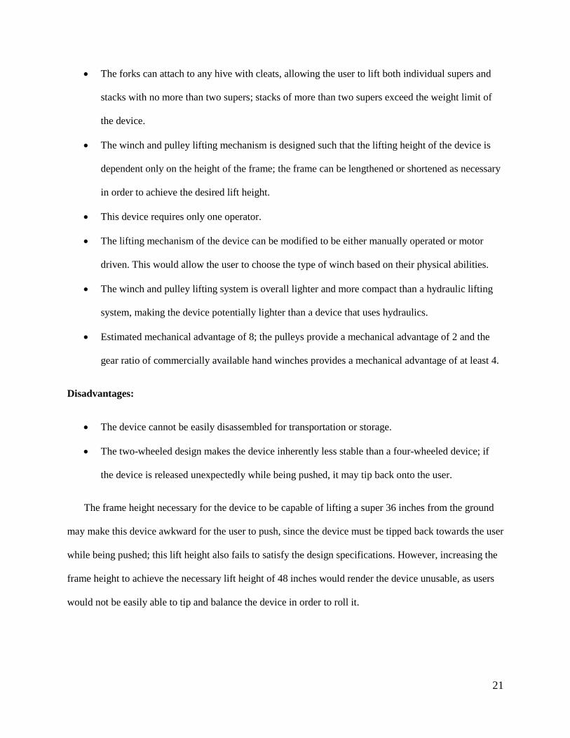
The forks can attach to any hive with cleats, allowing the user to lift both individual supers and
stacks with no more than two supers; stacks of more than two supers exceed the weight limit of
the device.
The winch and pulley lifting mechanism is designed such that the lifting height of the device is
dependent only on the height of the frame; the frame can be lengthened or shortened as necessary
in order to achieve the desired lift height.
This device requires only one operator.
The lifting mechanism of the device can be modified to be either manually operated or motor
driven. This would allow the user to choose the type of winch based on their physical abilities.
The winch and pulley lifting system is overall lighter and more compact than a hydraulic lifting
system, making the device potentially lighter than a device that uses hydraulics.
Estimated mechanical advantage of 8; the pulleys provide a mechanical advantage of 2 and the
gear ratio of commercially available hand winches provides a mechanical advantage of at least 4.
Disadvantages:
The device cannot be easily disassembled for transportation or storage.
The two-wheeled design makes the device inherently less stable than a four-wheeled device; if
the device is released unexpectedly while being pushed, it may tip back onto the user.
The frame height necessary for the device to be capable of lifting a super 36 inches from the ground
may make this device awkward for the user to push, since the device must be tipped back towards the user
while being pushed; this lift height also fails to satisfy the design specifications. However, increasing the
frame height to achieve the necessary lift height of 48 inches would render the device unusable, as users
would not be easily able to tip and balance the device in order to roll it.

22
5.1.2 Design 2: Four Wheel Hydraulic
Base: Concept two has an H shaped base with four 10
inch diameter rubber casters, seen in Figure 16. These
wheels will have the ability to move on
unimproved natural terrain such as fields. The H
shaped frame allows the two front feet to straddle
the stack of supers so the lifting forks can slide
under the cleats that are attached to each super.
Forks: These are the same as in Concept 1.
Rollers: These are the same as in Concept 1.
Hydraulic and Chain and Sprocket:
The main mechanism used for lifting is a
hydraulic system, seen in Figure 17. In this system a foot
pump is used to push fluid into the cylinder, lifting the piston. The hydraulic piston must have a stroke of
about 18 inches to achieve the maximum height needed. The hydraulic piston however only goes as low
Figure 16: Concept 2 fully lifted unloaded
Figure 17 Hydraulic Chain and Sprocket
Figure 21 Hydraulic Chain and Sprocket

23
as the top of the cylinder. To get past this disadvantage, a chain and sprocket will be attached. The length
of the chain will allow the rollers and essentially the forks to drop lower than the minimum cylinder
height. This will give the device the ability to pick up a hive from ground level.
Advantages:
The four wheel design gives it a larger footprint, making it less likely to tip. Unlike a two-
wheeled design, the user is not required to tip the device in order to push it; the device remains
flat on the ground, making it less likely to tip back onto the user. This feature also eliminates the
need for extra user strength input in order to tip the device back. Since the device remains in
contact with the ground in a stable position, the four-wheeled device, unlike a dolly, will not
crash to the ground if unexpectedly released by the user.
The forks used to pick up the hives ensure that the hives remain level while being lifted and
transported by the device.
The mechanical advantage is dependent on the piston and cylinder diameters of the hydraulic
system. In this current design, the hydraulic with a piston diameter of 1 inch and a cylinder
diameter of 4 inches, gives us a mechanical advantage of about 4. These components can be
replaced with ones of different dimensions to reach a higher mechanical advantage if need be.
Disadvantages:
The four wheel design requires a larger frame than a two-wheeled design using the same lifting
mechanism, making the device heavier than its two-wheeled counterparts. The larger frame also
impacts maneuverability, potentially making the device difficult to turn.

24
Figure 19, Rear Angled View, Concept 3 Loaded with 2 Supers
The number and size of the components necessary to create a hydraulic system also contribute to
the overall weight of the device. These components are heavier and more expensive than those
needed to create a lifting mechanism using a winch and pulley.
Some users may find a foot pump difficult to use.
Since the forks used to pick up the hives are fixed onto the device, the hives cannot be
repositioned or freely move while being held by the device.
5.1.3 Design 3: Four Wheel Winch and Pulley
This device combines the lifting mechanism from Concept 1 and the frame from Concept 2, as seen in
Figure 18 and Figure 19.
Advantages:
The advantages of Concept 2
Depending on the specific winch used, the device will be able to lock at intermediate heights, as
well as lifting and lowering the supers.
Figure 18Concept 3 Fully Lifted

25
The winch and pulley lifting mechanism means that the lifting height of the device is dependent
only on the height of the frame; the frame can be lengthened or shortened as necessary in order to
achieve the desired lift height.
The lifting mechanism of the device can be modified to be either manually operated or motor
driven. This would allow the user to choose the type of winch used in their device based on their
physical abilities.
The winch and pulley lifting system is overall lighter and more compact than a hydraulic lifting
system, making the device potentially lighter than a device that uses hydraulics.
Estimated mechanical advantage of 8; the pulleys provide a mechanical advantage of 2 and the
gear ratio of commercially available hand winches provides a mechanical advantage of at least 4.
Disadvantages:
The device cannot be easily disassembled for transportation or storage.
The four wheel design requires a larger frame than a two-wheeled design using the same lifting
mechanism, making the device heavier than its two-wheeled counterparts. The larger frame also
impacts maneuverability, potentially making the device difficult to turn.

26
5.1.4 Design 4: Rack and Pinion
The Rack and Pinion design was inspired by a
common machine shop drill press. A rack and pinion system
is able to convert circular motion into linear motion, making
this type of system ideal for raising and lowering objects.
This concept can be seen in Figure 20. As the user cranks the
gear, the teeth on the gear engage the rack and provide a
motion upward (or downward). Our design incorporated this
idea into a design suitable for lifting a Langstroth hive. The
rack and pinion design concept, seen in Figure 28, has a 36in
x42in U shaped base. This base is designed to straddle the
hive during the lifting process so that the center of mass of device would be more central, preventing the
device from tipping. Design 4 uses the rack and pinion system to crank the fork plate upward allowing the
successful lift of the hive. The hive can then be lowered onto the removable base plate seen in Figure 22,
to be transported to the desired location.
Figure 20 Drill Press Diagram by Creative
Commons Attribution, 2016, retrieved from
https://iescjmechanisms.wikispaces.com/RACK+AN
D+PINION+SYSTEM. .Copyright 2016 Tangient
LLC

27
Figure 21Concept 4 Fully Lifted Figure 22 Concept 4 Fully Lowered
Advantages
Estimated mechanical advantage from 3 to 6
Removable board in the base plate for transportability
Easy to break down into sub-assemblies
The device could be rolled up a ramp in order to load it onto a truck or trailer.
The device is well within the size limitations set by the design specifications—less than 66 inches
tall, 30 inches wide, and 48 inches long.
The forks can attach to any hive with cleats, allowing the user to lift both individual supers and
stacks no more than two supers.
The device requires only one operator.
Disadvantages
Requires custom gear box, which is costly

28
Crank moves vertically meaning the operator must be able to reach it at its highest and lowest
points
5.1.5 Design 5: Scissor Lift
Concept 5 is a Scissor Lift Cart. When fully lowered this design can act and operate as a standard
utility cart, as seen below in Figure 23.
The cart can be filled with essential beekeeping tools such as a pry bar and smoker. The back side
of the cart is on hinges and when unlocked, folds down to allow a table top plate (not shown here) to
move freely. This piece of the unit is described further below. The
wheels, 10 inch balloon tires, are mounted on axles, allowing them to
rotate. The front axle is mounted in a pivot block, allowing the entire
wheel subassembly to pivot about a vertical axis, for turning.
The device can be seen in its fully lifted form in Figure 24.
Figure 24 Concept 5 Fully Lifted
Figure 23Concept 5 Fully Lowered

29
Links:
Using a series of pantographs or links attached as parallelograms, the device can convert horizontal
motion into vertical motion. Figure 25 shows the locations of the
pin joints used in the device. Link 1 is fixed to the base and a
roller is mounted to the end of link 2 at joint 2. In reality the
roller pin is constrained by a slot which is more clearly seen in
Figure 26, shown below. This slot limits the horizontal motion,
which in turn limits the vertical height. Pins 3 through 6 allow
the angle between links to change freely. The pins attaching the
top plate to the links mirror the bottom pins, where pin 7 is fixed
and pin 8 is in a roller slot.
When fully extended, the links in commercial scissor lifts have an angle of about 40-45° from the
base. When lowered this angle decreases to about 10-20°. To achieve the minimum lift height of 48
inches, we can calculate the height of the device at its lowest point, the height of the device at its highest
point, these corresponding angles, the length of the links, as well as the stroke of the device.
Figure 25: Concept 5 pin joints
30
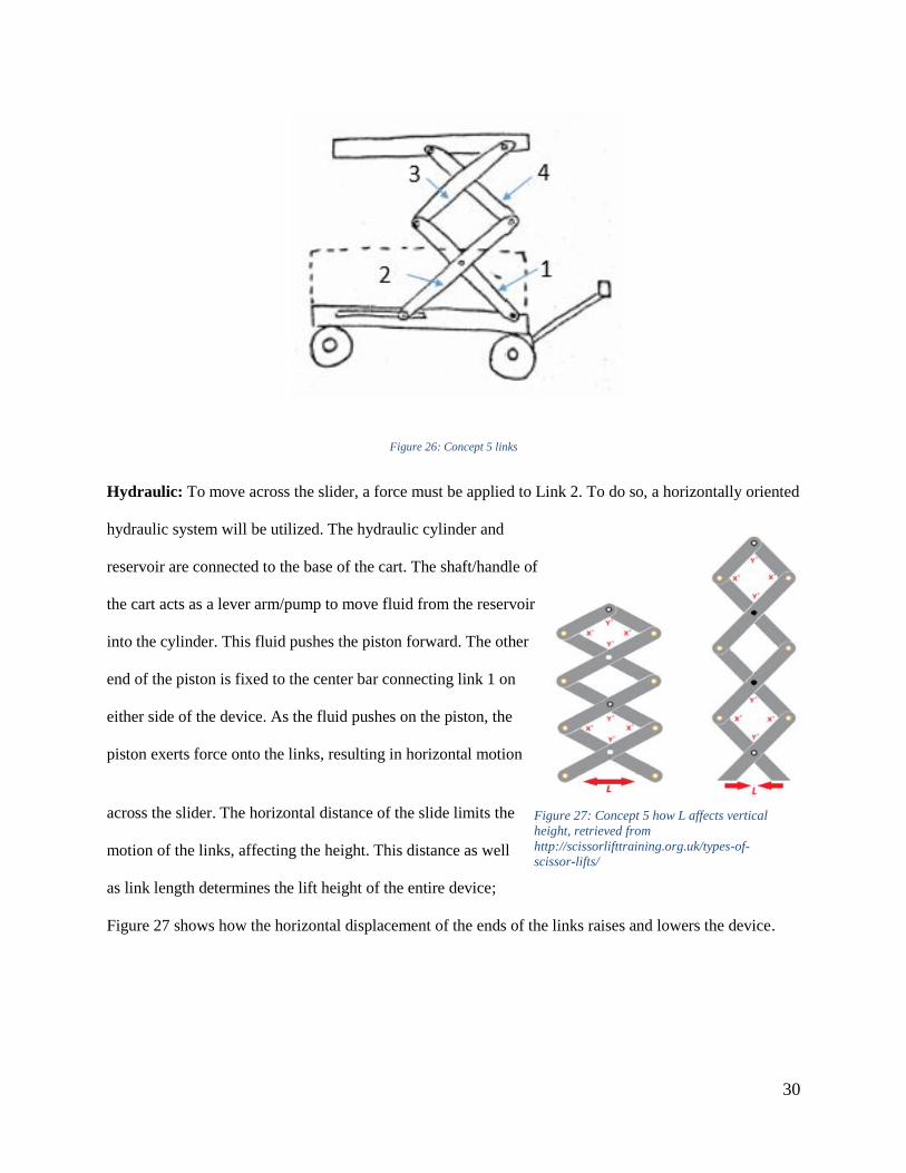
Figure 26: Concept 5 links
Hydraulic: To move across the slider, a force must be applied to Link 2. To do so, a horizontally oriented
hydraulic system will be utilized. The hydraulic cylinder and
reservoir are connected to the base of the cart. The shaft/handle of
the cart acts as a lever arm/pump to move fluid from the reservoir
into the cylinder. This fluid pushes the piston forward. The other
end of the piston is fixed to the center bar connecting link 1 on
either side of the device. As the fluid pushes on the piston, the
piston exerts force onto the links, resulting in horizontal motion
across the slider. The horizontal distance of the slide limits the
motion of the links, affecting the height. This distance as well
as link length determines the lift height of the entire device;
Figure 27 shows how the horizontal displacement of the ends of the links raises and lowers the device.
Figure 27: Concept 5 how L affects vertical
height, retrieved from
http://scissorlifttraining.org.uk/types-of-
scissor-lifts/

31
Figure 35: Concept 5 table top parts
Table Top:
The table top of the scissor lift will consist of multiple rollers.
The rollers will be covered by a plate that slips under a small lip on the
edges of the table. The operator can place a super onto the plate and
then slide the plate until it reaches the other end of the table top,
where. The plate can be fastened using a nut and bolt. This will keep
the plate fixed when moving both horizontally and when using the unit
for lifting. The rollers will allow easy, smooth motion with a lower
friction coefficient between the rollers and the bottom of the plate to
make moving the hives onto the table easier. The plate, on the other
hand, is being used for its friction on its top surface, stabilizing the
supers during movement. All of these parts can be seen in Figure 28. A
ratchet strap or other forms of fasteners can easily be used to secure
the hive onto the table without hindering the motion of the
device.
Advantages:
As mentioned previously, a four wheel design gives a larger footprint, making it less likely to tip.
The simple cart design makes operation easy and versatile. The type of axles used allows the
device to turn more easily.
Many components can be made from wood, decreasing overall cost and weight.
Figure 28: Concept 5 Tabletop Parts

32
Disadvantages:
The number and size of the components necessary to create a hydraulic system also contribute to
the overall weight of the device. These components are heavier and more expensive than those
needed to create a lifting mechanism using a winch and pulley.
This device does not pick up individual supers but rather requires the beekeeper to place the super
onto the table top. To do so an additional assistive device such as the two man bee hive carrier
will be required.
5.1.6 Design 6: Crane
The base of this device is a U shape made from a sheet of plywood with a square cut out from one
end. The device has four rubber casters with a diameter of 10 inches; one caster is connected to the
underside of each corner of the U, as seen in Figure 29. The shape of the base allows the front wheels of
the device straddle the stack of supers so that cable can be centered and attached.
Figure 29 Concept 6 Fully Lifted and Lowered

33
Attached at back end of the U is a vertical bar, centered between the rear wheels. This bar
provides the lift height of the device. Another bar extends forward, perpendicular to the vertical bar,
forming the crane arm. There are pulleys on the top of this bar at either end, as seen in Figure 29. A
winch is mounted midway up the vertical bar. The winch used should be capable of locking.
A rope or cable runs from the winch to the pulley mounted at the top of the frame and forward to
the pulley at the end of the arm. From there, the rope runs down through a hanging pulley and back up to
the top of the frame, where the end of the rope is fixed to a hook on the pulley at the top of the frame.
At the end of the cable, attached to the hanging pulley, are three chains with carabiners at the end.
These attach to hook-eyes attached to the hive frame.
The handle for pushing this device is a cylindrical bar attached to the mounting plate on the back
of the device by two vertical bars.
Advantages:
Same advantages as Concept 3
Disadvantages:
The device cannot be easily disassembled for transportation or storage.
The four wheel design requires a larger frame than a two-wheeled design using the same lifting
mechanism, making the device heavier than its two-wheeled counterparts. The larger frame also
impacts maneuverability, potentially making the device difficult to turn.
5.1.7 Design 7: Four Bar Linkage
The four bar device uses two wheels and is similar to a wheel barrel. The user can move the
device to the desired location by picking up the handle bar and wheeling it. This device, seen below in
Figure 30, would use a four-bar linkage to lift the hives and move them along a fixed path.

34
Z
Figure 30, Concept 7 Fully Lifted
Ideally, this path would lift the hives up and carry them back to rest on the base of the device, or
forward and up into the bed of a pickup truck. The four bar linkage design utilizes coupler curves for the
desired lifting path; coupler curves are used to generate the path followed by the coupler point, also
labeled in Figure 30. Our team used the software Linkages to synthesize a linkage design with a motion
that would satisfy the needs of the user. One of the curves we analyzed can be seen in in Figure 31. This
curve represents the motion the hive would follow during the lifting process. Unlike conventional lifting
devices which only have a vertical motion, the four bar linkage design follows a set path (known as a
coupler curve). The curve we synthesized not only lifts up but also lifts out and down. This could be
useful when picking up and putting down a hive in the desired location. The linkage is driven by a crank
which can be seen in Figure 30.

35
Figure 31 Concept 6 Coupler Curve
Advantages
The mechanical advantage of this device is estimated to be between 3 and 6.
Since the device is design almost entirely of wood, the overall cost is relatively low.
This design uses an advanced lifting motion called a coupler curve.
Large mountain bike wheels will be beneficial when maneuvering the device across natural
terrain.
Disadvantages
This design has major tipping issues and would require counter balance legs for stability.
The design is not easily disassembled. This makes transporting the device or loading it into a
truck bed difficult on the owners.
This device is not compatible with all hive stands, limiting the market.

36
5.1.8 Design 8: X Design
This concept functions similarly to a crane; it uses a winch and pulleys to lift the hives, and it lifts
them from above, as shown below in Figures 32 and 33.
Attachment point:
The device will use a clamping mechanism to attach to the hive. A toggle lever will be used to
apply force and lock the clamp into place. If oriented vertically, the attachment point on the hive will be
limited by the length of the clamps. Clamping onto a lower super than the top one may not be possible in
this case. If oriented horizontally, the attachment point on the hive would also be dependent on the length
of the chains. The chains are required to stabilize the hive such that it does not tip in any direction. A
solution to this would be to have attachable chain lengths, giving the operator the ability to pick up a
Figure 33 Concept 7 Side View Figure 32Concept 7 Isometric View
The body of the device
uses four large wheels for stability
and the ability to traverse natural
terrain. These wheels can be bike
tires ranging from 20-23 inches in
diameter. The top beam acts similar
to a crane to reach out above the
hive and lower the attachment point
into position.

37
partial stack of hives. Both possible configurations can be seen below in Figure 34.
Figure 34 Clamping Mechanism, Vertical and Horizontal Orientations

38
Lifting Mechanism:
The lifting mechanism
used in this device would be a
winch and pulley system. The
device uses two pulleys. With this
configuration the only mechanical
advantage would be from the
winch. However the addition of a
third pulley could provide
mechanical advantage from pulleys
of 2. The placement of the winch can be seen in Figure 35.
Counter Balance:
To counteract the weight in the front of the device, we have designed two beams that fold out
from the front of the device. The outriggers seen below in Figure 36 extend from the front of the device
due to an earlier misconception about how the outriggers would work; however, the outriggers would still
have the same form shown in the Figure. These beams extend the footprint of the device and provide a
reaction force that counters the weight of the hives. In order to allow for easier device storage, the
outriggers would fold up when not in use, as seen in Figure 37 below.
Figure 35 Concept 7 Winch

39
Figure 37 Concept 7 Counter Balance Folded Up
The team has also considered other possible methods of addressing the tipping problem. One
solution we have come up with is the use of a platform in the back. This platform would be attached to
fold out beams similar to what is shown above. The operator would then step onto this platform when
operating the winch. The operator’s weight would act as the counter weight for the device. Using their
bodyweight instead of sandbags or metal weights decreases the amount of weight they have to move
when maneuvering the device into place. The platform will be designed in such a way that it is practically
flush with ground, eliminated the need to step up onto it. This will also eliminate the need to design the
platform to withstand the entire weight of the operator. The platform will also be designed on a hinge
such that the platform is parallel to whatever incline the ground is.
Figure 36 Concept 7 Counter Balance Extended

40
5.1.9 Design 9: Box Design
The box design, Figure 38, uses a winch and pulleys as the lifting device. The winch and pulley
system can achieve a mechanical advantage of around 8 and is ideal for making the lifting job easier.
This design is unique because it can break down into separate pieces for transportation purposes.
The frame of this design would be built in two parts, the lifting frame and the base; the dashed
line in Figure 38 shows the divide between the upper and lower halves of the device. These two parts
would be bolted together, allowing for repeated assembly and disassembly. Like the X design, this device
would use some sort of clamping mechanism as the attachment point. This design also uses a winch and
pulley system; in this system, as in the proposed X design system, the mechanical advantage is solely
derived from the winch, with the possible addition of another pulley allowing for increased mechanical
advantage if necessary. This design uses large mountain bike tires to allow the device to maneuver
unimproved natural terrain.
This design, like the X design, would need some sort of counterbalance or stabilizers in order to
prevent tipping.
Figure 38 Box Design Side View

41
Advantages
The estimated mechanical advantage of this device is between 4 and 8.
Large mountain bike wheels will be beneficial when maneuvering on natural terrain.
This device has the ability to break down into smaller sub-assemblies for transportation purposes.
This device is designed to work with a variety of hive stands.
The materials used in this design are relatively easy to purchase since the device is mostly wood.
Disadvantages
This design is very heavy as a whole unit.
This design also presents tipping issues that would need a counter balance.
5.2 Design Selection Process
Following analysis, the devices were scored using a decision matrix, as described below. The
categories were given a weight based on their importance relative to one another. These weights and
scores were used to determine which of the designs was “best” based on how well it satisfied the matrix
criteria.
5.2.1 Pairwise Comparison
The team used a tool called a pairwise comparison to help determine which criteria were
considered most important. Each row and column is compared to each other, and if the category in the
column is considered more important, a 1 is placed in the box; if not, a 0 is placed in the box. If they are
considered to be equally important, a 0.5 is placed in the box. To find the weight for each category, the
equation below is used.
𝑤𝑒𝑖𝑔ℎ𝑡 =𝑇𝑜𝑡𝑎𝑙 𝑓𝑜𝑟 𝑜𝑛𝑒 𝑐𝑎𝑡𝑒𝑔𝑜𝑟𝑦
𝑇𝑜𝑡𝑎𝑙 𝑜𝑓 𝑎𝑙𝑙 𝑡ℎ𝑒 𝑐𝑎𝑡𝑒𝑔𝑜𝑟𝑦 𝑡𝑜𝑡𝑎𝑙𝑠
The completed pair-wise comparison can be seen in Figure 39.

42
Completed Pair-wise Comparison
Figure 39 Pairwise Comparison

43
5.2.2 Decision Matrix
Each concept design was rated based on how well it met certain specifications that could be
analyzed at this stage in the design process. That score would then be multiplied by the weight of
importance based on the pairwise comparison. These numbers were then totaled to see which device best
satisfied the design criteria. An example matrix can be seen below in Figure 40.
5.2.3 Decision Matrix Criteria
The following section contains a description of each category used in the decision matrix, along with the
criteria used in determining the score that each device received in each category.
Weight of Lifting Mechanism
How much will the weight of the lifting mechanism contribute to the overall weight of the device?
· 1 = ≥ 61 lbs.
· 2 = 51-60 lbs.
· 3 = 31-50 lbs.
· 4 = 21-30 lbs.
Figure 40 Sample Decision Matrix

44
· 5 = ≤ 20 lbs.
Unit weight needs to be low enough to operate the device on various terrains. These numbers are based on
the anthropometric data found for females age 51-70, which was used to calculate that 68% of users in
this age range have the ability to push up to 277lbs. up a 5 degree slope. The team aims to have a total
weight of the fully loaded device be around 275 lbs, to minimize the users’ strength requirements. If the
weight of the lifting mechanism is too great, it is more likely that the device will be too heavy for some
users to push, regardless of the materials used to build the frame of the device.
Mechanical Advantage
· 1= No mechanical advantage
· 2= 1-4
· 3= 5-8
· 4= 9-12
· 5= >12
The goal of the project is to create a lifting device that reduces the amount of weight that the user has to
lift. A device with a higher mechanical advantage requires less user strength input. The average amount of
weight that 68% of women between the ages of 51 and 70 years old can pull is about 22 lbs.; in order for
these women to be able to operate a lever or crank that is lifting a 200 pound load, the minimum
mechanical advantage required is roughly 9. Devices that require user input in the form of pushing do not
require quite as much mechanical advantage, due to the fact that women in the same range can push with
about 33 lbs.
Maximum Lift Height

45
Can it lift the bottom of the super to 48 in?
· 1 = less than 36 inches
· 2 = 37-42 inches
· 3 = 43-48 inches
· 4 = 49-54 inches
· 5 = 55 inches or greater
Lift height is defined as the maximum height the device can lift the bottom of a super from ground level.
While stacks can vary in height, the average height of stacked supers on a stand is about 46 inches from
the ground; a lift height of 48 inches or greater would allow the user to lift a stack of two supers off of a
hive stand, while smaller lift heights would only allow for the lifting of a single super.
Complexity of System
How many components does the lifting mechanism require?
· 1 = 10 or more components
· 2 = 7-9 components
· 3 = 5-7 components
· 4 = 3-5 components
· 5 = < 3 components
In addition to adding to the overall weight and cost of the lifting device, lifting systems that involve more
parts have a higher potential for part failure, resulting in additional maintenance costs. The greater
46
number of parts can, at times, also make the device more difficult for the user to assemble and/or use. In
order to reduce the potential for such difficulties, systems with fewer parts are preferred.
Components are defined as individual parts of the system. In a hydraulic device, for example, the
components would be the hydraulic cylinder, the reservoir, the pump, hydraulic fluid, and the tubing used
to connect the system. In a winch and pulley system, the components would be the winch, 2 pulleys, the
rope or cable, and any additional apparatus that might be used to attach the hive to the mechanism.
Cost of Lifting Mechanism
Is it expensive?
· 1 = Greater than $400
· 2 = $351-400
· 3 = $300-350
· 4 = $250-299
· 5 = less than $250
Since many beekeepers run on a small scale and tend to only break even, cost is very important. A device
that is too costly will not appeal to many customers, narrowing the market. While the overall frame of the
device can be modified to reduce costs, there are fewer modifications available for the lifting mechanism
used, making the lifting mechanism the main factor in the cost of the device.
Safety
Is there significant potential for user injury?
● 1 = more than 6 obvious pinch points or sharp edges
● 2 = 5-6 obvious pinch points or sharp edges

47
● 3 = 3-4 obvious pinch points or sharp edges
● 4 = 1-2 obvious pinch points or sharp edges
● 5 = No obvious pinch points or sharp edges
To prevent injury to the operator, reducing the number of pinch points and sharp edged is essential.
Overall Dimensions
Will the device fit within a 66 inch high, 30 inch wide, and 56 inch long box?
● 1 = off by >3 inches in multiple dimensions
● 2 = off by >3 inches in one dimension
● 3 = within 3 inches in all dimensions
● 4 = yes it fits
● 5 = overall dimensions are smaller
5.3 Preliminary Analysis for Designs and Scoring Rationale
To determine which raw score each design received, preliminary analysis of each design must be done.
The following sections provide the results for each design and explanations of why each device received
the score that it did.

48
5.3.1 Design 1: Two Wheel Dolly
Table 2 Two Wheel Dolly Results
Category Result
Weight of Lifting Mechanism (Estimate) 40 lbs.
Mechanical Advantage 8
Maximum Lift Height 35.5 in
Complexity of Lifting Mechanism 7 components
Cost of Lifting Mechanism (Estimate) $185
Safety 3 pinch points
Overall Size 66in x 32in x 38in
The Two Wheel Dolly design scores a 3 in lifting mechanism weight because the estimated
weight is about 40 lbs. The estimated cost for all devices was generated based on prices of commercially
available parts. The design scores a 3 in mechanical advantage because the combination of a
commercially available hand-crank winch combined with a system of two pulleys produces a mechanical
advantage of 8. The maximum lift height of this device in its current configuration is only 35.5 inches,
which scores a 1; this lift height could be increased, but it would be at the expense of both the overall cost
and overall weight of the device. The lifting mechanism of the device includes 7 components: the winch,
two pulleys, a rope or cable, two forks, and the rolling apparatus that connects the forks to the frame. This
gives the device a score of 3 in the complexity category. The estimated cost of the lifting mechanism of
the device, generated through the same process as the weight estimate, is about $185; this scores a 5. In
the safety category, the device scores a 3, due to the fact that there are only 3 pinch points present: the
winch and the rollers on either side of the rolling apparatus. Finally, the overall size of this device is 66in
x 32in x 38in. Since this is 8 inches wider than the maximum allowable dimensions, the device scores a 2
in the size category.

49
5.3.2 Design 2: Four Wheel Hydraulic
Table 3 Four Wheel Hydraulic Results
Category Result
Weight of Lifting Mechanism (Estimate) 40 lbs
Mechanical Advantage 4
Maximum Lift Height 44 in
Complexity of Lifting Mechanism 9 Components
Cost of Lifting Mechanism (Estimate) $256
Safety 3 pinch points
Overall Size 66in x 48 in x 27.56 in
The Four Wheel Hydraulic design scores a 3 in lifting mechanism weight because the estimated
weight is about 40 lbs. The design scores a 2 in mechanical advantage because the estimated mechanical
advantage from an appropriately sized hydraulic cylinder and pump system is 4. The maximum lift height
of this device in its current configuration is only 35.5 inches, which scores a 2; this lift height could be
increased, but it would be at the expense of both the overall cost and overall weight of the device. The
lifting mechanism of the device includes 9 components: the hydraulic cylinder, the pump, a chain and
sprocket, the tubing that connects the pump and cylinder, the reservoir for the fluid, two forks, and the
rolling apparatus that connects the forks to the frame. This gives the device a score of 3 in the complexity
category. The estimated cost of the lifting mechanism of the device, generated through the same process
as the weight estimate, is about $260; this scores a 5. In the safety category, the device scores a 3, due to
the fact that there are only 3 pinch points present: the pump handle and the rollers on either side of the
rolling apparatus. Finally, the overall size of this device is 66in x 48in x 28in. Since this is smaller than
the maximum allowable dimensions, the device scores a 5 in the size category.

50
5.3.3 Design 3: Four Wheel Winch and Pulley
Table 4 Four Wheel Winch Results
Category Result
Weight of Lifting Mechanism (Estimate) 40 lbs.
Mechanical Advantage 8
Maximum Lift Height 38 in
Complexity of Lifting Mechanism 7 components
Cost of Lifting Mechanism (Estimate) $185
Safety 3 pinch points
Overall Size 80in x 30in x 48in
The Four Wheel Winch and Pulley design scores a 3 in lifting mechanism weight because the
estimated weight is about 40 lbs. The design scores a 3 in mechanical advantage because the combination
of a commercially available hand-crank winch combined with a system of two pulleys produces a
mechanical advantage of 8. The maximum lift height of this device in its current configuration is 38
inches, which scores a 2. The lifting mechanism of the device includes 7 components: the winch, two
pulleys, a rope or cable, two forks, and the rolling apparatus that connects the forks to the frame. This
gives the device a score of 3 in the complexity category. The estimated cost of the lifting mechanism of
the device is about $185; this scores a 5. In the safety category, the device scores a 3, due to the fact that
there are only 3 pinch points present: the winch and the rollers on either side of the rolling apparatus.
Finally, the overall size of this device is 80 in x30 in x 48in. Since this is about 14 inches taller than the
maximum allowable dimensions, the device scores a 2 in the size category.
5.3.4 Design 4: Rack and Pinion
Table 5 Rack and Pinion Results
Category Result
Weight of Lifting Mechanism (Estimate) 30 lbs
Mechanical Advantage 3
Maximum Lift Height 33 in
Complexity of Lifting Mechanism 6 components worm, gear rack, gear, handle, forks
Cost of Lifting Mechanism (Estimate) $450
Safety 3 pinch points
Overall Size 52in x 36in x 42in

51
The Rack and Pinion design scores a 3 in lifting mechanism weight because the estimated weight
is about 30 lbs. The design scores a 3 in mechanical advantage because the ratio of the gears used
produces a mechanical advantage of 3. The maximum lift height of this device in its current configuration
is only 33 inches, which scores a 1. The lifting mechanism of the device includes 6 components: the
worm, the gear rack, the gear, the crank handle, and the two forks. This gives the device a score of 3 in
the complexity category. The estimated cost of the lifting mechanism of the device, generated through the
same process as the weight estimate, is about $450; this scores a 2. In the safety category, the device
scores a 3, due to the fact that there are only 3 pinch points present: the interface between the gear and
rack, the interface between the worm and gear, and the crank. Finally, the overall size of this device is
52in x 36in x 42in. Since this is 6 inches wider than the maximum allowable dimensions, the device
scores a 2 in the size category.
5.3.5 Design 5: Scissor Lift
Table 6 Scissor Lift Results
Category Result
Weight of Lifting Mechanism (Estimate) 40 lbs
Mechanical Advantage 4
Maximum Lift Height 33 in
Complexity of Lifting Mechanism 11 Components
Cost of Lifting Mechanism (Estimate) $260
Safety 10+ pinch points
Overall Size 66in x 48 in x 28 in
The Scissor Lift design scores a 2 in lifting mechanism weight because the estimated weight is
about 40 lbs. The design scores a 2 in mechanical advantage because the available piston and cylinder
diameters we have currently found only produce a mechanical advantage of 4. The maximum lift height
of this device in its current configuration is only 33 inches, which scores a 2. The lifting mechanism of
the device includes 10 components: 8 links, hydraulic, and foot pump. This gives the device a score of 1
in the complexity category. The estimated cost of the lifting mechanism of the device, generated through
the same process as the weight estimate, is about $260; this scores a 4. In the safety category, the device
scores a 1, due to the fact that there are multiple pinch points created by the folding links. Finally, the

52
overall size of this device is 66 in x 48 in x 28 in. Since this fits in within the designated space, the device
scores a 5 in the size category.
5.3.6 Design 6: Crane
Table 7 Crane Results
Category Result
Weight of Lifting Mechanism (Estimate) 15 lbs.
Mechanical Advantage 8
Maximum Lift Height 38 in
Complexity of Lifting Mechanism 6 components
Cost of Lifting Mechanism (Estimate) $35
Safety 1 pinch points
Overall Size 70in x 36in x 42in
The Crane design scores a 5 in lifting mechanism weight because the estimated weight is about
15 lbs. The design scores a 3 in mechanical advantage because the combination of a commercially
available hand-crank winch combined with a system of two pulleys produces a mechanical advantage of
8. The maximum lift height of this device in its current configuration is 38 inches, which scores a 2. The
lifting mechanism of the device includes 6 components: the winch, three pulleys, a rope or cable, and the
apparatus that attaches the rope or cable to the hives. This gives the device a score of 3 in the complexity
category. The estimated cost of the lifting mechanism of the device is about $35; this scores a 5. In the
safety category, the device scores a 4, due to the fact that there is only 1 pinch point present: the winch.
Finally, the overall size of this device is 70in x 36in x 42in. Since this is 4 inches taller and 6 inches wider
than the maximum allowable dimensions, the device scores a 1 in the size category.
5.3.7 Design 7: Four Bar Linkage
Table 8 Four Bar Linkage Results
Category Result
Weight of Lifting Mechanism (Estimate) 25 lbs
Mechanical Advantage 6
Maximum Lift Height 43 in
Complexity of Lifting Mechanism 14 components
Cost of Lifting Mechanism (Estimate) $150
Safety 5 pinch points
Overall Size 80in x 32in x 73in

53
The Four Bar Linkage design scores a 4 in lifting mechanism weight because the estimated
weight is about 25 lbs. The design scores a 3 in mechanical advantage because the gear ratio produces a
mechanical advantage of 6. The maximum lift height of this device in its current configuration is 43
inches, which scores a 3. The lifting mechanism of the device has at least 14 components: 8 links, 2 bars
connecting the two sides of the linkage, the chain that attaches to the hive, and the crank and associated
gears. This gives the device a score of 1 in the complexity category. The estimated cost of the lifting
mechanism of the device is about $150; this scores a 5. In the safety category, the device scores a 2, due
to the fact that there are only 3 pinch points present: the crank and the two points on either side of the
device where the linkages move against the frame. Finally, the overall size of this device is 80in x 32in x
73in. Since this is 14 inches taller, 2 inches wider, and 15 inches longer than the maximum allowable
dimensions, the device scores a 1 in the size category.
5.3.8 Design 8: X Design
Table 9 X Design Results
Category Result
Weight of Lifting Mechanism (Estimate) 15 lbs
Mechanical Advantage 8
Maximum Lift Height 22 in
Complexity of Lifting Mechanism 3 components
Cost of Lifting Mechanism (Estimate) $35
Safety 1 Pinch Point
Overall Size 42 in x 30 in x 54 in
The X design scores a 5 in lifting mechanism weight because the estimated weight is only about
15 lbs. The design scores a 3 in mechanical advantage because the combination of a commercially
available hand-crank winch combined with a system of two pulleys produces a mechanical advantage of
8. The maximum lift height of this device in its current configuration is only 22 inches, which scores a 1.
The lifting mechanism of the device includes 6 components: the winch, two pulleys, a rope or cable, and
eyehooks. This gives the device a score of 3 in the complexity category. The estimated cost of the lifting
mechanism of the device, generated through the same process as the weight estimate, is about $35; this

54
scores a 5. In the safety category, the device scores a 3, due to the fact that there is only 1 pinch point
present: the winch. Finally, the overall size of this device is 42 in x 30 in x 54 in. Since this extends
outside of the maximum allowable dimensions, the device scores a 3 in the size category.
5.3.9 Design 9: Box Design
Table 10 Box Design Results
Category Result
Weight of Lifting Mechanism (Estimate) 15 lbs
Mechanical Advantage 8
Maximum Lift Height 43 in
Complexity of Lifting Mechanism 5 components
Cost of Lifting Mechanism (Estimate) $35
Safety 1 pinch point
Overall Size 74in x 32in x 50in
The Box Dolly design scores a 5 in lifting mechanism weight because the estimated weight is
about 15 lbs. The design scores a 3 in mechanical advantage because the combination of a commercially
available hand-crank winch combined with a system of two pulleys produces a mechanical advantage of
8. The maximum lift height of this device in its current configuration is 43 inches, which scores a 3. The
lifting mechanism of the device includes 3 components: the winch, three pulleys, and a rope or cable. This
gives the device a score of 3 in the complexity category. The estimated cost of the lifting mechanism of
the device is about $35; this scores a 5. In the safety category, the device scores a 4, due to the fact that
there is only 1 pinch point present: the winch. Finally, the overall size of this device is 72in x 32in x 50in.
Since this is 6 inches taller and 2 inches wider and longer than the maximum allowable dimensions, the
device scores a 2 in the size category.
With each of these designs analyze and rated, the decision matrix can be filled with the results. This can
be seen on the following page in Figure 41.

55
Figure 41 Decision Matrix

56
Figure 42 Secondary Pairwise Comparison
According to this matrix the Box Design scored the highest and would be the best design to
develop. However, since the X design, Box Design and Crane scored so closely, we revisited each device
with new categories: Total Unit Weight, Hive Stand Feasibility (how many types of hives stands the
device will work with), and Ability to Transport Hives (Can the device move the hives to another
location?). A new pair-wise comparison was created as well as another decision matrix to compare these
top three designs. These can each be seen in Figure 42 and Figure 43.
Considering these new categories, The X design is considered the best design to further develop.
While the Box design has a close total score, the overall weight of the unit itself would be too substantial
for operator to easily use when loaded. The X design scored poorly in the transportation category mostly
due to the concept not being developed enough at the time to see how it would work in that aspect.
Regardless of this fact the team decided to select this design and believed we could optimize it in such a
way that if rated again afterwards, its transportation score would increase.
Figure 43 Secondary Decision Matrix

57
6.0 Final Design
After selecting a concept, the team fully developed the design in SolidWorks, performed analysis
on critical points in the design in order to ensure that the device would not fail at these points, and
selected the final components to be used in the device.
6.1 Parts and Assemblies
After selecting a concept, the team modeled the device in its entirety in SolidWorks. The full
device can be seen below in Figure 44.
Figure 44 Isometric View of Device
This device uses the wheels, axles, and steering handle from a utility cart; the cart that we used can be
found at http://www.tractorsupply.com/tsc/product/groundwork-1-200-lb-capacity-utility-cart. Rather
than using the cart itself, which is excessively long and harder to attach the frame to, the base of the
device is constructed from 2x4s and 2x6s in a rectangular configuration, as shown in Figure 45, with the
axles oriented so that the steerable wheels are at the rear of the device. The steerable wheels are labeled in

58
Figure 44. The 2x6s in the middle were substituted in place of 2x4s when it became apparent that the
axles from the cart could not be securely attached to 2x4s, which do not extend down far enough in this
configuration. The base of the device is covered by a sheet of plywood, which allows the hives to sit on
the base during transportation.
Figure 45 Top View of Device Base
The lift height of the device comes from the extended triangle- shaped frame shown in Figure 46.
This frame is constructed into triangles, each consisting of a long 2x4 (crane arm) that runs diagonally
from the rear of the device to the front and a shorter vertical 2x4 that supports the crane arm. This can be
seen in Figure 46 below.

59
The vertical supports are connected to
the diagonal beams with bolts and metal plates.
The upper end of the vertical support and the point where it meets the diagonal are sandwiched between
two metal plates, and the bolts run through the holes in the metal plates. The triangular side frames are
connected by two horizontal 2x4s, one at the end of the crane arm where the pulley attaches and one
midway up the arm, as shown in Figure 46. The winch attaches to the rear of the device on a “handle”
made from three 2x4s, seen in Figure 44 and Figure 46. This entire upright frame bolts onto the base of
the device in order to allow the user to separate the two parts of the device for easier transportation and
storage.
Extending from the front of the base of the device are two outriggers, as seen in Figure 46. These
adjustable outriggers are designed to prevent the device from tipping when lifting the 200lb load. The
outriggers are made from aluminum pipe, cut to the appropriate length to prevent tipping, as determined
by our analysis, and are attached to the device using adjustable flagpole brackets.
Figure 46: Side View of Device
60
Attachment point:
The device uses a ratchet strap to attach to the hive. The ratchet strap wraps horizontally around
the lowest hive in the stack that the user wants to lift. There are three metal D-rings, spaced equidistantly
around the hive on the ratchet strap, which serve as the attachment point for the device. The cable that
runs through the winch splits into three chains with carabiners on the ends, which clip into the D-rings.
The chains are required to stabilize the hive such that it does not tip in any direction. However, if the
chains are long enough to reach the lowest hive in the stack, a significant amount of lift height may be
lost when attempting to lift a single hive. A possible solution to this would be to have attachable chain
lengths, giving the operator the ability to pick up a partial stack of hives.
Lifting Mechanism:
The lifting mechanism used in this device is a winch and pulley system. While the system
originally called for a two pulley system in order to increase the mechanical advantage sufficiently, this is
not necessary with the winch being used; the system uses a single pulley, attached to the cross beam,
shown in Figure 47, to change the direction of the force applied by the winch. The winch used for the
device must be non-back drivable, so that the hives do not come crashing down when the winch is
released.

61
Figure 47Front View of Device
6.2 Analysis
Static and stress analysis was conducted on the critical points of the device, as well as individual
parts to ensure functionality before being built and tested. Our calculations were focused on tipping, the
stress on the beam on which the pulley was mounted, and crane arm. In the following analysis we used a
load value of 250 lbs, instead of our recommended 200 lbs, as a built in safety factor in case the operator
overloads the device.
6.2.1 Tipping
To ensure that the device does not tip when fully loaded, we conducted an analysis on all of the
external forces on the device. A free body diagram of the loaded device can be seen in Figure 48.

62
We started by summing the forces and moments on the device. Using these equations, we wanted to solve
for the length of the outriggers needed to prevent the device from tipping forward.
Σ𝑀𝐵↺ = 0: 𝐹𝐴(30.5) + 95(14.6) − 250(15) + 𝐹𝑜𝐿𝑥 = 0 (1)
𝐹𝐴(30.5) + 𝐹𝑜𝐿𝑥 = −2363𝑙𝑏𝑖𝑛 (2)
According to these equations, the device is considered statically indeterminate, meaning there are too
many unknowns to solve for any set variable. As a result, we had to consider material properties and
calculated the force at the outrigger 𝐹𝑜 by using equation 𝑌𝑆 =𝐹𝑜𝐿𝑐
𝐼, where 𝑌𝑆the yield strength of
Figure 48 Tipping Analysis

63
aluminum, L is is the length of the outrigger, c is the location of the centroid, and I is the area moment of
inertia.
This value of 𝐹𝑜 was the plugged into equation 2, seen above. 𝐿𝑥 is dependent on the chosen length of the
outriggers and where the outrigger is attached, which the team originally chose to be 24 inches long and
20 inches from the ground. Through multiple iterations using Excel, we were able to find a value of 𝐹𝐴
that was greater than zero, meaning that the device would not tip forward. The spreadsheet used can be
found in the appendix and the final values can be seen below.
Table 11 Tipping Calculation Values
Yield
Strength
40 kpsi
c 0.6575 in
I 0.0757
L 28.5 in
𝐹𝑜 115.111 lbs
𝐹𝐴 0.84575 lbs
The maximum length of the outrigger is 28.5 inches. When this value is increased, the value for 𝐹𝐴
decreases below zero. If the length of the outrigger decreases to 20, the force, 𝐹𝑜, is essentially zero.
Therefore, the length of the outrigger must be between 21 and 28.5 inches long.
6.2.2 Double Fixed Pulley Beam
In this analysis we wanted to solve for the maximum stress in the cross-beam to which the pulley
is attached and determine if the wood beam will fail with a load of 250lbs.

64
The static analysis for this beam can be seen below.
Σ𝑀𝐴↺ = 0: − 250(15) + 𝑅𝐵(30) = 0
𝑅𝐵 = 125 𝑙𝑏𝑠
𝑅𝐴 = 125 𝑙𝑏𝑠
𝑀𝑚𝑎𝑥 =𝐹250𝐿
8
𝑀𝑚𝑎𝑥 = 937 𝑙𝑏 ∗ 𝑖𝑛
Using this value for 𝑀𝑚𝑎𝑥 we were able to solve for the stress in the beam.
𝐼 =𝑏ℎ3
12𝑖𝑛4
𝐼 =(1.5)(3.5)3
12= 5.359 𝑖𝑛4
𝜎 =𝑀𝑚𝑎𝑥𝑐
𝐼
𝜎 =937(1.75)
5.359= 305.981 𝑝𝑠𝑖
Figure 49 Double Fixed Beam
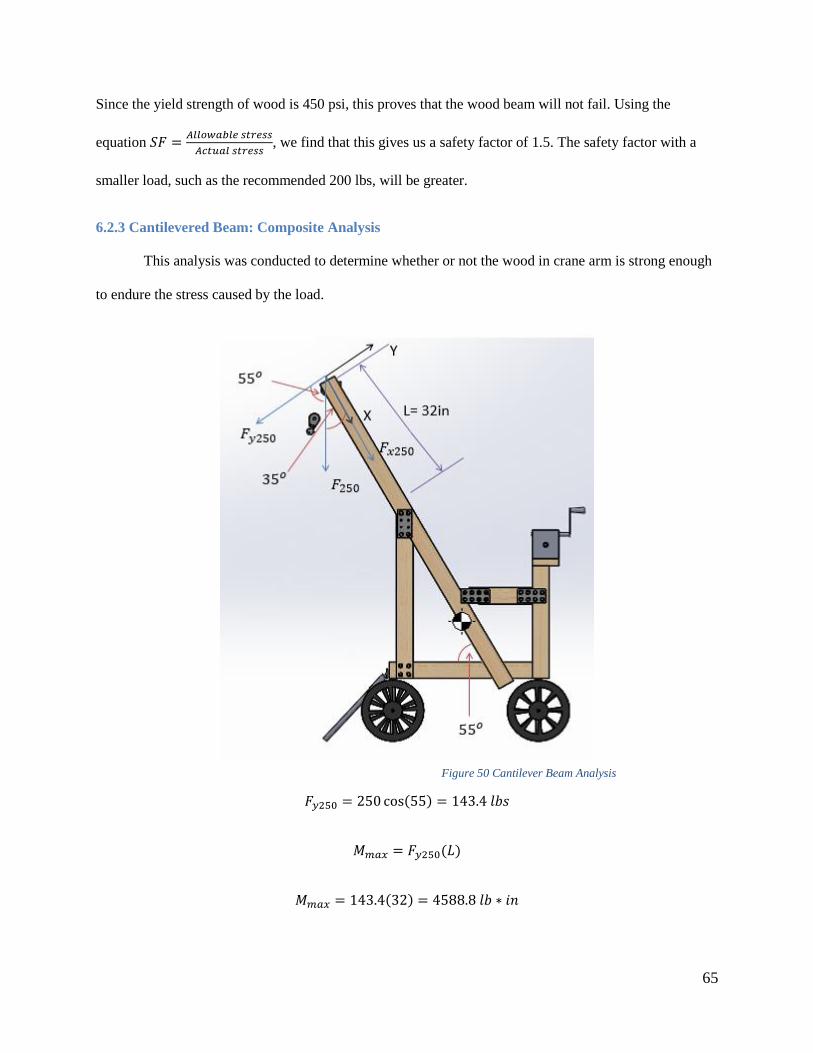
65
Since the yield strength of wood is 450 psi, this proves that the wood beam will not fail. Using the
equation 𝑆𝐹 =𝐴𝑙𝑙𝑜𝑤𝑎𝑏𝑙𝑒 𝑠𝑡𝑟𝑒𝑠𝑠
𝐴𝑐𝑡𝑢𝑎𝑙 𝑠𝑡𝑟𝑒𝑠𝑠, we find that this gives us a safety factor of 1.5. The safety factor with a
smaller load, such as the recommended 200 lbs, will be greater.
6.2.3 Cantilevered Beam: Composite Analysis
This analysis was conducted to determine whether or not the wood in crane arm is strong enough
to endure the stress caused by the load.
𝐹𝑦250 = 250 cos(55) = 143.4 𝑙𝑏𝑠
𝑀𝑚𝑎𝑥 = 𝐹𝑦250(𝐿)
𝑀𝑚𝑎𝑥 = 143.4(32) = 4588.8 𝑙𝑏 ∗ 𝑖𝑛
Figure 50 Cantilever Beam Analysis
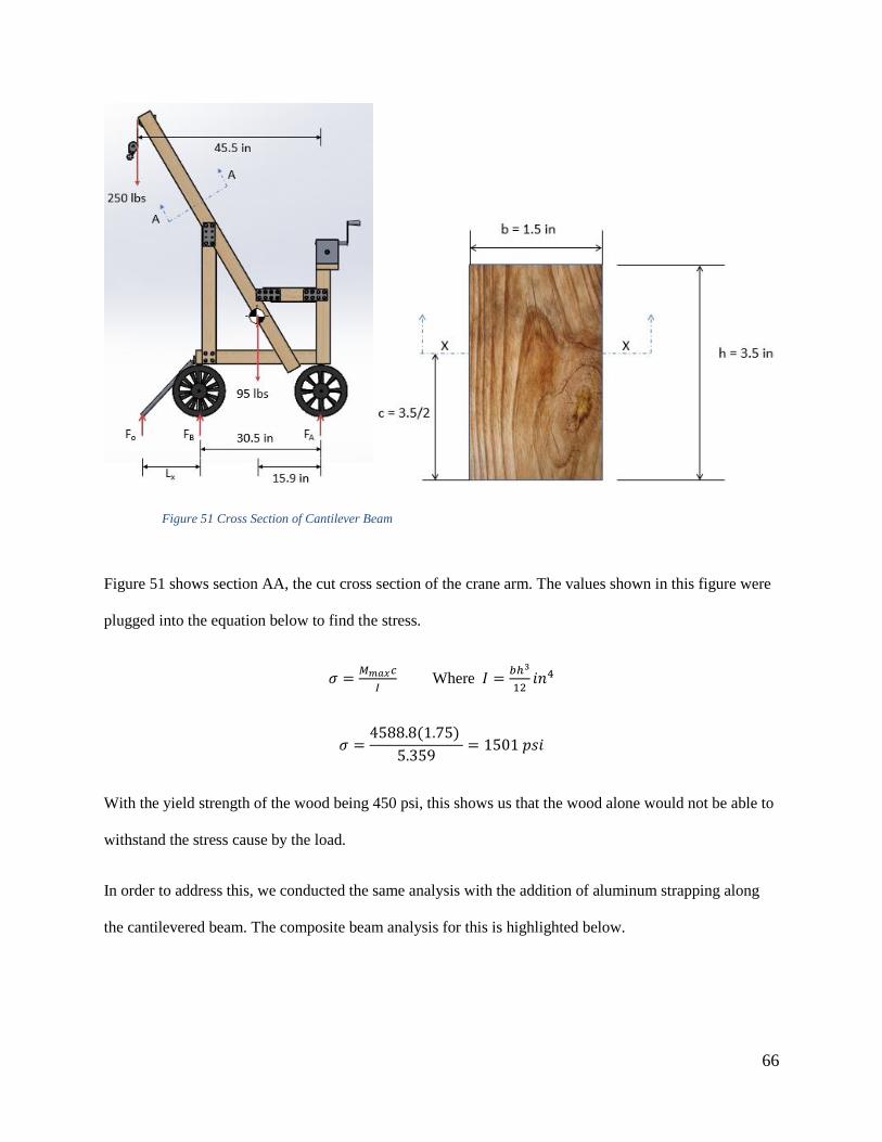
66
Figure 51 shows section AA, the cut cross section of the crane arm. The values shown in this figure were
plugged into the equation below to find the stress.
𝜎 =𝑀𝑚𝑎𝑥𝑐
𝐼 Where 𝐼 =
𝑏ℎ3
12𝑖𝑛4
𝜎 =4588.8(1.75)
5.359= 1501 𝑝𝑠𝑖
With the yield strength of the wood being 450 psi, this shows us that the wood alone would not be able to
withstand the stress cause by the load.
In order to address this, we conducted the same analysis with the addition of aluminum strapping along
the cantilevered beam. The composite beam analysis for this is highlighted below.
Figure 51 Cross Section of Cantilever Beam

67
The strapping used was a piece that was 0.125 in by 1 in dimension. This piece of material was then
transformed to find the equivalent strength dimensions in wood. The transformation factor n is
determined by finding the ratio of the elastic modulus of each material.
𝑛 =𝐸𝑎𝑙
𝐸𝑤𝑜𝑜𝑑=
10,300,000
900,000= 11.44
This value is then multiplied by the original values of b and h, giving the transformed values 𝑏𝑇 =
1.43 𝑖𝑛 and ℎ𝑇 = 11.44 𝑖𝑛 .
To find the area moment of inertia for the composite beam we used the equation𝐼 = 𝐴1𝑥12 + 𝐴2𝑥2
2. With
values of 𝑥1 = 2.86 𝑖𝑛 and 𝑥2 = 0.875 𝑖𝑛 for the distance from the centroids for each block to the neutral
axis, and 𝐴1 = 8.1796 𝑖𝑛2 and 𝐴2 = 2.625 𝑖𝑛2 for the areas, gives a value of 68.91 𝑖𝑛4 for𝐼𝑐𝑜𝑚𝑝. With
this new value for 𝐼𝑐𝑜𝑚𝑝 and using the same equation for stress used previously, we get 𝜎 = 380.9 𝑝𝑠𝑖
and a safety factor of 1.18. While this number is considered low, this is in the case that all the weight is
loaded onto one beam. In reality the load of 250 lbs is distributed across two beams, thus giving us a
higher safety factor.
Figure 52 Cross Section, Wood and Aluminum
Figure 53 Cross Section, Transformed Aluminum and Wood
68
6.3 Final Component Selection
Based on our analysis the only change made to the design was adding the additional aluminum
strapping to the cantilevered top beam. This prevents the wood from critically failing, making the device
operational.
6.3.1 Mechanical Advantage
The final design has a mechanical advantage of 20. This is entirely due to the winch we have
selected which ensures a smooth lift and corresponds with the orientation in the design. The original
design had a two pulley system; however, with the winch mechanical advantage being so large, the extra
pulley was unnecessary.
7.0 Prototype
After determining the final design through modeling, stress, statics and final component selection,
the prototype was built and tested.
7.1 Assembly
The assembly process of the prototype involved three stages. Stage one, ordering all needed
components and parts. Stage two, fabricating the prototype. Stage three, documenting the fabrication
process so as to make detailed assembly instructions for future users.
7.1.1 Ordering Parts
The majority of parts required for this project were standard off the shelf items that could be
purchased at any hardware store. We found all the needed parts from three locations: Mcmaster-Carr,
Home Depot, and the Tractor Supply Co. Figure 54 shows a spreadsheet of all items purchased, the part
number (if applicable), the quantity ordered, the price per one of the item, and lastly the total cost of the
item based on the quantity ordered. The total cost of all purchased items is located at the bottom of Figure
54. This cost is over the desired target of $500; however, the cost can be substantially reduced by

69
eliminating unnecessary items and replacing expensive items with cheaper substitutes. For instance, the
two highest costing items were the precise positioning winch and the 1200lb GW utility cart. These items
together cost approximately $265.32. Although these items are necessary, we found that the cost of these
items could be reduced by a $100 dollars by simply replacing them with cheaper items.
The cost of the 6in x 3in aluminum plates was $96. Although eight of these aluminum plates were
ordered, we found that none are necessary. All eight aluminum plates could be replaced by standard 2x4s.
The necessary adjustments would require ordering longer 8mm bolts to compensate for the thickness of
the 2x4s replacing the aluminum plates, and drilling holes into the wood. The cost reduction for replacing
the aluminum plates with wood is $96.
Of the four load rated corner brackets, we found only two were necessary. The other two can be
replaced by wood 2x4s. The cost reduction of replacing two load rated corner brackets with 2x4s is
$22.66.
The three OB long chain links cost a total of $37.14 and have a lifting capacity of 3,800lbs. This
was well over the lifting capacity needed for out project. We investigated load rated zip ties from
Mcmaster-Carr as a replacement. They have a capacity of 120lbs and come in a pack of ten for around
$10. The cost reduction for substituting the OB long links with load rated zip ties is $27.14.
The total cost reduction of replaceable items was $245.8. If we subtract this from out total
material cost, the price becomes $546.2.

70
Figure 54Bill of Materials
7.1.2 Fabrication and Detailed Instructions of Assembly Steps
Fabrication of the beehive lifting device involved cutting pieces of wood and drilling holes so that
they could be fastened together. The following sections provide assembly drawings which detail the parts
needed to fabricate individual sub-assemblies. The section concludes by showing how each of the three
sub-assemblies forms the main assembly.
Base:
The base required seven pieces of wood cut to length and thirty three 3 inch deck screws. Two
screws were placed at every base joist and on both sides. The rear end of the base has two 2x4 joists
screwed together to form a single 4x3 joist. The 4x3 joist was simply screwed together tightly with five 3
inch deck screws. The load rated corner brackets are screwed into the top of the 4x3 joist on both ends

71
using eight 3 inch deck screws (4 screws per bracket). Four screw holes must be drilled into the load rated
corner brackets before screwing them into the base. This was completed using a .106 drill and can be seen
in Figure 55 below.
Figure 55Drilling Holes in Corner Bracket
A 30in x 30in sheet of ply wood was also placed over the top of the base at the end of the build.
The individual part drawings for the base can be found in the appendix, and the model and exploded
model of the base can be seen below in Figures 56 and 57.

72
Figure 56 Base Assembly

73
Figure 57 Base Exploded Assembly
Top:
The top half of the beehive lifting device required eight pieces of wood cut to length. The column
2x4 beam of this sub-assembly was cut at a 55 degree angle with a chop saw. We set the chop saw to a 35
degree angle and cut the beam vertically. Cutting the beam in this fashion left us with a 55 degree angle.
Figure 58 below shows the orientation of the cut.

74
Figure 58Orientation of Cut for Column
Once the crane arm and crane column beams were cut to length and the holes were drilled, it was
necessary to fasten the two parts together. In order to do this, both parts were laid flat onto the floor. The
column beam was positioned at a distance of 31.38 inches away from the top beam. One 6in x 3in
aluminum plate was placed over the desired connection point. A black sharpie was then used to mark
where the holes needed to be drilled on both parts. After these holes were drilled, another 6in x 3in
aluminum plate was lined up with the first aluminum plate on the other side of the beam and used to
sandwich the beams. Four 8mm bolts were used to fasten the two beams together.

75
The pulley mount beam was fastened in between the uprights using four 4 inch deck screws (two
screws on each side). This beam has no exact measured height; it is fastened at the uppermost point at the
end of the two long diagonal beams. When fixing this beam to the uprights, the 4inch side of the 2x4 is
perpendicular to the ground. A level was used to make sure the beam was not tilted to one side. For extra
support, two 1in x 1in angle braces were placed at the ends of the each beam, shown below in Figure 59.
Figure 59 Top Beam with Angle Bracket

76
A second pulley beam was placed between the uprights, 8 inches from the bottom of the crane
arm beam. This can be seen below in Figure 60.
Figure 60Support Beam
This beam was positioned so that the 4inch side of the 2x4 was perpendicular to the thickness
(2inch side) of the crane arm beam. The second pulley beam does not require holes to be drilled into it; It
is just a 2x4 cut to length.
The pulley was then fixed to the pulley beam using four 10-32 bolts, washers, and nuts.

77
Aluminum strapping was screwed into the crane arm along 4 inch face of the beam using twelve
1 inch deck screws. Before this could be done, 12 holes were drilled into the aluminum strapping with a
.106 drill. These holes were spaced 2.5 inches apart.
Two 10-inch long 2x4s were screwed into the crane arm column beams using four 3 inch deck
screws (two screws per side). This was done so that the flagpole outriggers could be fastened to the
columns with ease. The flag pole outriggers were fastened to the crane arm column beams using eight 3
inch deck screws (four screws per side).
Once the top sub-assembly, shown below in Figure 61, Figure 62, and Figure 63, was completed,
it was fastened to the base using a total of ten 8mm bolts (five bolts per side).

78
Figure 61 Top Assembly

79
Figure 62 Top Assembly Exploded

80
Figure 63Top Assembly Half Exploded View
Winch Mount:
The winch mount required five pieces of wood cut to length. Holes were drilled into the top 2x6
beam so that the winch may be mounted to it; the location of these holes was determined by the spacing
of the holes on the winch (mounting holes vary depending on type of winch). The top 2x6 beam was
screwed into the two vertical beams using four 3 inch deck screws (2 on each side).

81
The winch was bolted to the top 2x6 beam with four 8mm bolts. Four M8 washers and nuts were
used to fasten the winch down to the wood. This can be seen below in Figure 64 and Figure 65.
Figure 64 Winch Mount Exploded

82
Figure 65Winch Mount
We then added the wood angle beams for extra support. In order to do this, we cut the wood at a
35 degree angle. We then placed the two wood angle beams between the uprights and the winch mount
vertical beams. This can be seen in Figure 66.

83
Figure 66 Wood Angle Beams
Wheel Sub-Assembly:
The wheel sub-assemblies were taken from the GW 1200lb utility cart. The cart came with two
wheel frames and four wheels that were mounted to the frames. The frame for wheel sub-assembly 1 was
mounted at the rear end of the base. Wheel sub-assembly 1 has a four bar linkage system meant for
steering the beehive lifting design. Wheel sub-assembly 2 has a fixed frame and was mounted on the front
end of the base. Both wheel frames were attached to the base using four 3 inch deck screws and four M10
washers (two per frame, one on each side). The frames were then fastened to the holes in the 2x6 base
joists using four 8mm bolts and nuts (two per frame). The instructions for both wheel sub-assemblies can
be found in Appendix A.4.
Lifting Method:
The lifting method involves two scenarios: lifting a single super and lifting an entire hive. When
lifting one super, our method involved one ratchet strap, three OB long chain links, three lifting straps,
and three carabiners. The three OB links were placed over the ratchet. The ratchet was then fastened
horizontally around a single super. Before tightening the ratchet strap all the way, the OB links were

84
positioned as a triangle around the super (one in back, two up front). Making the lift connection point a
triangle ensured that the super would not tilt when moving. The three lifting straps were placed through
the OB links and carabiners were used to secure the straps at the center of the super. This setup was
connected to the crane hook via the carabiner and then lifted. A picture can be seen in Figure 67.
Figure 67Single Super Attachment
When lifting the entire hive, two ratchet straps were used to fasten the hive together tightly. The
crane hook was then attached to the S hook on the ratchet strap and then lifted. The key to this lifting
method is tightening the ratchet strap so that the S hook connection point is directly in the center. If not

85
picked up directly from the center, the hive has a tendency to tilt when lifted. Figure 68 shows the entire
hive.
Figure 68 Entire Hive Attachment
Outriggers:
The outriggers were needed to prevent the device from tipping when lifting the full load. We used
adjustable flag pole holders made out of aluminum. These flag pole holders have the ability to lock in
place at different angles using a nut that connects a set of teeth together. This is shown in Figure 69
below.

86
Figure 69 Adjustable Outriggers
Final Assembly:
The final assembly required fastening the three main sub-assemblies together. First, the top sub-
assembly was fastened to the base using ten 8mm bolts (five bolts per side). These bolts were
accompanied by 20 M8 washers (two washers per bolt on either side), and ten M8 nuts.
The winch mount sub assembly was lined up so that the vertical beams of the winch mount sub-
assembly was flush with the length beam on the base and attached using load-rated corner brackets on the
base. Using a sharpie, we marked holes that needed to be drilled in the vertical beams. We then drilled the
holes using a .375 drill. After drilling the holes, we fastened the winch mount sub-assembly to the base
using the sixteen 8mm bolts (eight bolts per side). Once the device was fully assembled, we began testing.
Figure 70 below shows the final assembled device from multiple angles, while Figure 71 shows
and exploded view.

87
Figure 70Multiple Views of Device

88
Figure 71Exploded View of Device
Figure 72, Figure 73, and Figure 74 show the upper and lower assemblies of the device, as well as
all of the fasteners used to assemble the device.

89
Figure 72 Upper and Lower Assemblies
Figure 73Base and Cover Plate with Fasteners

90
Figure 74Upper Assembly with Fasteners
7.2 Field Testing
Field testing was done to determine the success of our project based on our design specifications.
7.2.1 Maneuverability
In order to test maneuverability, the team moved the device up inclines and on natural terrain in
both loaded and unloaded conditions. The team was unable to schedule a visit with the Metcalfs to test the
device on their properties however we brought the device to Institute Park which has grass covered hills.
Pulling a fully loaded device on the grass was relatively easy for a woman but became difficult as the
incline increased which was expected. The turn radius was also measured by wetting the tires and
measuring the circle created by the tire tracks. This gave us a turn radius of 33 inches.
7.2.2 Lifting Capabilities
For this testing, the team obtained a bee hive (without bees) and used the device to lift different
weights of the super. This was be conducted by filling the empty hive with weights and lifting the entire
hive into the bed of truck.

91
We tested the device’s ability to lift single supers and a stack consisting of one shallow, one
medium, and one deep super. We simulated the full stack of hives by filling them with 210 lbs of weights.
We tested the device’s ability to lift this load both from ground level and from the height of the average
hive stand, about 15 inches from the ground. We simulated the weight of a single super by filling one
super with 75 lbs of weight and lifting it from ground level and from the height of the average hive stand.
In both cases, we also tested maneuvering the hives onto the platform on the base of the device.
7.2.3 Transportability and Storage
We tested the transportability and storage of the device by attempting to lift the device into the
bed of a truck and testing how neatly it fit. We tested the device both in its fully assembled configuration
and with the top and bottom halves of the device separate from one another. While the device fits well in
both cases, separating the top and base make the device fit more securely when strapped down with
bungee cords as well as make it easier to lift each piece into the bed of a pick-up.
7.2.4 Field Test Results & Adjustments
The testing of the device’s lifting capabilities showed that the device is fully capable of lifting
single hives as well as stacks weighing up to 210 lbs. However, when we attempted to maneuver the hives
onto the platform for transportation, we found that the middle cross beam on the device obstructed the
path of the hives. In order to address this, we moved the beam towards the back of the device, so that it
was no longer in the way.
The transportability and storage testing showed that the device is capable of fitting in the bed of
the average pickup truck. However, it is a tight fit, meaning that there would not be room for both the
device and the hives in the bed of the truck; it would be necessary for the user to have a trailer or some
other means of transporting the hives. We also found that, when the device is fully assembled, it fits most
easily when it is upright in the bed of the truck. This is not recommended, though, as we found it difficult
to secure the device sufficiently in order to prevent movement of the device when the truck is in motion at

92
normal road speeds. Finally, when both fully assembled and dissembled, the device is generally difficult
to lift into the bed of the truck without the help of a second person. This could be remedied by
disassembling the device further. At the current moment it takes about ten minutes to separate the top part
of the device from the base, using a ratchet wrench and pliers. Further disassembly would take more time
but ultimately decrease the weight of each sub assembly. The addition of handles on either side of the
base would also facilitate easier lifting of the device.
8.0 Results and Discussion
Overall, this device meets the goals of this project. It is capable of lifting the necessary weight,
can transport hives, and costs less than commercially available beekeeping-specific devices with similar
capabilities. There are some concerns about the overall size and weight of the device. With the device at
about 120 lbs, disassembled each piece weighs nearly as much as a super. This almost defeats the purpose
of making a device that eliminates the need to physically move that much weight. However, the device
will have to be assembled and transported much less than what is need to maintain and move supers,
therefore the design is still practical. Also of concern is the choice of winch, which has an unnecessarily
high mechanical advantage, resulting in excessively slow lifting. To crank the winch from ground to the
highest point takes about 1minute and 5 seconds (118 revolutions). From the top of a hive to the highest
point takes about 20 seconds (30 revolutions). The winch also has the potential for over cranking, which
improperly loads the cross beam and may cause it to fail. This occurs when the super is fully lifted,
however the operator continues to turn the winch. Finally, the attachment method could be improved
upon to keep the hives level. Despite these concerns, the team considers this device to be a success.
Comparing our final design to our original design specifications, some areas of concern arise. The
unit weight exceeds our design specification by 45 lbs and exceeds our original dimensions of height of
66 in, and width of 30 in and a length of 56 in. The prototype we have made measures a height of 76
inches, 33 inches in width, and 50 inches in length (from the tip of the pulley beam to the back of the

93
base). While this exceeds our design specification, it still is capable of fitting into the bed of a pick-up
truck as well as through a doorway. The overall cost also was a concern as it almost doubled our goal cost
of $400.
On the other hand, the device did surpass our requirement of lifting 200lbs and was analyzed to
be able to withstand much more. According to the anthropometric data for torque the device only requires
10 lbs of input force, while operators in this age group can input as much as 21 lb-in force.
9.0 Conclusion and Recommendations
The goal of this project was to build a cost effective device that is stable, has a high mechanical
advantage, and is easily replicable. We believe that we have achieved this goal. The materials used are
readily available from a local hardware store or ordered online. The total cost was $792, which is higher
than we anticipate the materials will cost for the beekeepers. We purchased extra materials, such as bolts
and wood, to ensure we did not run out during the building process. Some of the materials were purchased
could also be replaced with more cost effective options while still working with this design.
Testing indicated that this device can lift both individual supers and stacks of hives, weighing up
to 200 lbs and transport them. We also found that the device fits in the bed of a pickup truck; however, we
recommend that users only attempt to load the device into a truck with the help of another person, due to
the awkward shape of the device, even when it is broken down into two parts.
One recommendation we can make is that the beekeepers purchase a different winch. The one we
selected has an excessively large mechanical advantage and was more expensive than other usable
models. Because of this, the lifting process is smooth, but very slow. A winch with a lower mechanical
advantage can be purchased, and by using a multi-pulley system, the lifting mechanism as a whole will
have a large enough mechanical advantage to easily lift the same amount of weight. We also recommend
that the operator be cautious of the direction they turn the winch. Over cranking it can cause excess stress
on the pulley support beam. While we added extra supports to the design, proper use of the winch is

94
critical. To prevent over cranking the winch, the operator might mark the maximum lift point with tape
and make note of which direction the winch must be turned in in order to raise or lower the hives.
Additionally, we recommend that the user purchase a fixed pulley that is made to be fixed in the
orientation used in this design.
We also recommend that the attachment system in which the cable is attached to the hives is
further researched. Creating a universal design that is both cost effective and practical for the people who
are replicating this design was part of the process we hoped to work more on; however were unable to do
to due to time constraints. One concern with our design is that with only three attachment points, on three
sides of the hive, the hive will tip. According to Jim Metcalf, this should not bother the bees in any way.
Despite this, a more consist lift is preferred. While our solution does work, we believe another design
could be more efficient.

95
References:
About Winches. (n.d.). Retrieved September 28, 2015, from http://www.thomasnet.com/about/winches-
94054806.html
Apilift Professional APL02M. (n.d.). Retrieved April 26, 2016, from
http://www.lpsbiodling.se/sv/artiklar/redskap/apilift-professional-apl02m.html
Bach, J. C. (n.d.). The Status and Future of Washington Apiculture (Beekeeping). 1-5. Retrieved March 2,
2016, from http://agr.wa.gov/FoF/docs/Bees.pdf
BEEKEEPING EQUIPMENT. (n.d.). Retrieved April 26, 2016, from
http://www.aces.uiuc.edu/vista/html_pubs/BEEKEEP/CHAPT2/chapt2.html
Berr. (2003). Strength Report. Retrieved October 11, 2015
Brain, Marshall. How Tower Cranes Work.Retrieved September 27, 2015
Cranes — Mobile cranes. (n.d.). Retrieved April 26, 2016, from
https://law.resource.org/pub/us/cfr/ibr/003/bs.en-13000.2004.html
David Burns; Sheri Burns. (n.d.). Honey Super. Retrieved from HoneyBeesOnline.com:
http://www.honeybeesonline.com/honey-super/
Hive Carrier. (n.d.). Retrieved April 26, 2016, from http://www.brushymountainbeefarm.com/Hive-
Carrier/productinfo/935/
Hydraulic and Pneumatic Systems. (n.d.). Retrieved April 26, 2016, from
http://www.oocities.org/rjwarren_stm/College_Physics/Hydraulics.html
Jabr, F. (2013,). The Mind-Boggling Math of Migratory Beekeeping. Retrieved September 27, 2015.
King Materials Handling ~. (n.d.). Retrieved April 26, 2016, from
http://www.kinggroup.com.au/lifters.htm
The Langstroth Bee Hive. (n.d.). Retrieved April 26, 2016, from http://www.dave-
cushman.net/bee/lang.html
Lantrip, J. (2003). Fundamentals of tool design (5th ed.). Dearborn, Mich.: Society of Manufacturing
Engineers.
Lee, K. (n.d.). The Importance of Pollinators. Retrieved September 27, 2015.
Life in the Hive. (n.d.). Retrieved September 28, 2015, from
http://www.bbka.org.uk/learn/general_information/life_in_the_hive

96
LT-330SL Light Duty Scissor Lift Table. (n.d.). Retrieved April 26, 2016, from
http://www.maxmaterialhandling.com/lt-330sl-light-duty-scissor-lift-table-p195.html
MacLeod, D. (2013). The rules of work: a practical engineering guide to ergonomics (2nd ed.). Boca
Raton, FL: CRC Press.
Mechanical advantage device. (n.d.). Retrieved April 26, 2016, from
https://en.wikipedia.org/wiki/Mechanical_advantage_device
Northern Industrial Tools Winch-Operated Pickup Truck Crane — 1000-Lb. Capacity. (n.d.). Retrieved
April 26, 2016, from http://www.northerntool.com/shop/tools/product_74569_74569
Pallet Jacks - Best Deal Pallet Jacks - Pallet Jack Special. (n.d.). Retrieved April 26, 2016, from
http://akflow.com/index.cfm?mf=browse.showpart
Politicians Are Poody Heads. (n.d.). Retrieved April 26, 2016, from
https://poodyheads.wordpress.com/tag/ratchet-effect/
Pollination: Managing Bees for Pollination. (n.d.). Retrieved from University of Georgia College of
Agricultural & Environmental Sciences: http://www.ent.uga.edu/bees/pollination/managing-bees-
pollination.html
Pulleys. (n.d.). Retrieved September 28, 2015, from http://www.explainthatstuff.com/pulleys.html
"Pulley" (25 August 2009). HowStuffWorks.com. Retrieved 03 October 2015.
Push Pull Toggle Clamps, Latch Type Toggle Clamps, Toggle Latches, Pneumatic Fastening Clamps.
(n.d.). Retrieved April 26, 2016, from http://www.jwwinco.com/products/section15/
RACK AND PINION SYSTEM. (n.d.). Retrieved April 26, 2016, from
https://iescjmechanisms.wikispaces.com/RACK AND PINION SYSTEM
Scissor Lift Jack Equations and Loading Calculator - Engineers Edge. (n.d.). Retrieved April 26, 2016,
from http://www.engineersedge.com/mechanics_machines/scissor-lift.htm
THE BEEKEEPER'S YEAR. (n.d.). Retrieved from Back Yard Beekeepers Association:
http://www.backyardbeekeepers.com/to-do.html
The Benefits of Gearboxes - and When to Pick Integrated Gearmotors. (n.d.). Retrieved September 28,
2015.
THE BEST BEE HIVE. (2015). Retrieved from BEE THINKING: http://www.beethinking.com/pages/the-
best-bee-hive

97
Toggle clamp advantages and comparison sp1. (n.d.). Retrieved September 28, 2015.
http://www.slideshare.net/toggleclamp/toggle-clamp-advantages-and-comparison-sp1
Toggle clamps. (n.d.). Retrieved September 28, 2015. http://www.lizhida.net/blog/toggle-clamp-
introduction/
Types of Scissor Lifts. (n.d.). Retrieved April 26, 2016, from http://scissorlifttraining.org.uk/types-of-
scissor-lifts/
Understanding the Inner Workings: How Hydraulic Cylinders Work. (n.d.). Retrieved April 26, 2016,
from http://cylinderjacks.com/education/understanding-cylinder-inner-workings.html
Toggle action force factors. (n.d.). Retrieved April 26, 2016, from http://www.steelsmith-
clamps.eu/toggle_action_force_factors
Warren Forensics. (n.d.). Retrieved April 26, 2016, from
http://www.warrenforensics.com/2013/04/09/crane_balancing_act/
Weber, N. (n.d.). Why Do Farmers Need Beekeepers? Retrieved September 27, 2015.
Wesco® Compact Lift Truck Hand Operated Winch with Platform 260152 500 Lb. (n.d.). Retrieved April
26, 2016, from http://www.globalindustrial.com/p/material-handling/lift-trucks/manual-lift/compact-li-
truck-hand-operated-w-with-platform-500-lb-capacity
Winch. (n.d.). Retrieved September 28, 2015, from http://www.vedruna-
angels.org/vangels/antiga/clicseso/AULAVATEC/Mecanismes/Topic99.HTM
Winches. (n.d.). Retrieved September 28, 2015, from http://auto.howstuffworks.com/auto-
parts/towing/equipment/hitch-accessories/winches.htm
1/2 ton Capacity Hand Winch. (n.d.). Retrieved April 26, 2016, from http://www.harborfreight.com/1000-
lb-capacity-hand-winch-65688.html

98
Appendix
A.1 Lifting Mechanism
A.1.1 Winch
Winches are one of the simple mechanisms that can be used for lifting. A winch is defined as a
mechanism that winds a cable or rope around a drum while keeping a steady tension on the cable
(Winches, n.d.). In their simplest form, winches consist of a spool and attached hand crank, while more
elaborate designs have gear assemblies to create additional mechanical advantage and/or a mechanical
brake or ratchet and pawl device to prevent unwinding (Winches, n.d.). Within the mechanism, the crank
is attached to a very small gear which meshes with a larger gear inside the winch that directly or
indirectly rotates the spool, as seen in Figure 1A.
Figure 2A Winch, by Haul Master, 2016, retrieved from http://www.harborfreight.com/1000-lb-capacity-hand-winch-65688.html
The mechanical advantage in the winch is created when the arm of the handle is longer than the
diameter of the cylinder and through the ratio between the smaller gear and the larger gear; however,
while each turn of the crank equals one turn of the smaller gear, it only results in a fraction of a turn of the
larger gear (Winch, n.d.). As a result, a large number of crank rotations are required to move the cable a
relatively small distance.

99
The winch could potentially be used in a lifting device structured similarly to a forklift, with a
tower or similar structure that the hive follows when being raised and lowered, as seen below in Figure
2A.
Figure 3A Winch Lift Truck, Global Industrial, 2016, retrieved from http://www.globalindustrial.com/p/material-handling/lift-
trucks/manual-lift/compact-li-truck-hand-operated-w-with-platform-500-lb-capacity. Copyright by Global Equipment Company
Inc
In a device like this one, a pulley is used to change the direction of the force applied to the cable, while
the winch is used to change the length of the cable, raising or lowering the attached platform as needed.
Another application of winches in lifting devices that could be used to lift a beehive is as the
lifting mechanism in a crane, such as the one pictured below in Figure 3A.

100
Figure 4A Crane with Winch, by Northern Industrial Tools, 2016, retrieved from
http://www.northerntool.com/shop/tools/product_74569_74569Copyright © Northern Tool + Equipment
In this type of device, the cable attaches directly to the object being lifted and passes over a pulley that
changes the direction of the force on the cable. The object being lifted is raised and lowered by turning
the handle attached to the winch. Most of these winches also have the ability to lock, preventing the lifted
object from slipping.
A.1.2 Pulley
Another simple lifting mechanism is the pulley, a collection of one or more wheels over which a
rope is looped (Pulleys, n.d.). Pulleys work by multiplying forces and allowing for the reversal of the
direction of a lifting force (a pulling force applied to one end of the rope is turned into a lifting force on
the attached load at the other end) (Pulleys, n.d.). While a single fixed pulley can only reverse the
direction of the applied force, a mechanical advantage can be generated with the addition of more pulleys
(Pulley, 2009). When a combination of fixed and movable pulleys are used with a single rope passing
through the set of pulleys, a mechanical advantage equal to the number of lengths of rope supporting the

101
movable pulleys is generated; a 100 lb block, for example, only requires 25lbs of force to be lifted when a
system of 4 pulleys is used (Pulley, 2009). This can be seen in Figure 4A.
Figure 5A Mechanical Advantage of Pulleys retrieved from https://en.wikipedia.org/wiki/Mechanical_advantage_device
However, while each additional wheel reduces the amount of lifting force needed, it also
increases the distance over which the force must be exerted to achieve the same amount of lift (Pulleys,
n.d.), such that in a system of two wheels, 2m of rope movement is required in order to generate 1m of
lift.
A.1.3 Crane
Cranes are a third type of lifting mechanism. They use one or more simple machines to create
mechanical advantage (Brain, n.d.). The first of the mechanisms most commonly used in cranes is the
lever, which is used in balance cranes. In its simplest form, cranes contain a beam that pivots about a
fulcrum, which allows a heavy load to be attached to the long end of the beam and be lifted by a
proportionately smaller force applied in the opposite direction on the shorter end of the beam (Brain,
n.d.). The mechanical advantage created by the lever is the ratio of the lengths of the long arm and the
short arm, which is equivalent to the ratio of the load’s weight to the applied force. The crane in the figure
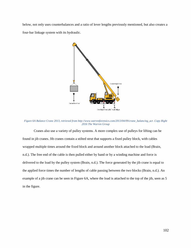
102
below, not only uses counterbalances and a ratio of lever lengths previously mentioned, but also creates a
four-bar linkage system with its hydraulic.
Figure 6A Balance Crane 2013, retrieved from http://www.warrenforensics.com/2013/04/09/crane_balancing_act .Copy Right
2016 The Warren Group
Cranes also use a variety of pulley systems. A more complex use of pulleys for lifting can be
found in jib cranes. Jib cranes contain a stilted strut that supports a fixed pulley block, with cables
wrapped multiple times around the fixed block and around another block attached to the load (Brain,
n.d.). The free end of the cable is then pulled either by hand or by a winding machine and force is
delivered to the load by the pulley system (Brain, n.d.). The force generated by the jib crane is equal to
the applied force times the number of lengths of cable passing between the two blocks (Brain, n.d.). An
example of a jib crane can be seen in Figure 6A, where the load is attached to the top of the jib, seen as 5
in the figure.

103
Figure 7A Jib Crane, 2016, retrieved from https://law.resource.org/pub/us/cfr/ibr/003/bs.en-13000.2004.html
A system of pulleys could be employed in a beehive lifting device to first change the required input force
from a pulling force to a lifting force, with additional pulleys to reduce the amount of input force needed
to lift the hive. Since a system of pulleys requires a greater amount of cable movement on the input end of
the system than on the output end, a great deal of slack or excess cable would be produced on the input
side as the hive is lifted. A winch could be added to contain the extra cable and provide additional
mechanical advantage.
While cranes provide a significant advantage in lifting, they are not without their drawbacks,
especially the issue of stability. In order to prevent the crane from overturning, the sum of all moments
about the base of the crane must be close to zero (Brain, n.d.). In the case of cranes mounted on a
movable base, this means that additional components such as locking wheels and counterweights must be
considered.
However, a pure crane mechanism has some potential issues as a beehive lifter. The lever arm
necessary to lift the hive to the height of a truck bed would likely be fairly long, making the device
excessively bulky and difficult to maneuver. Additionally, in a traditional crane, the object being lifted is
only secured at the connection point at the end of the cable. This allows for the potential for the object

104
Figure 8A Ratchet Diagram, Word
Press, 2016, retrieved from
https://poodyheads.wordpress.com/tag/r
atchet-effect/
being lifted, in this case a beehive, to swing. While the beekeepers assured us that this would not disrupt
the bees themselves, this should be avoided to prevent excess stress to the device. Despite these
drawbacks, however, components of a crane may still be useful for a beehive lifting device.
A.1.4 Ratchet
The ratchet mechanism is a device that allows continuous rotary motion in one direction while
preventing motion in the opposite direction (Mekanizmaler, 2013). This mechanism consists of a round
ratchet wheel with teeth and a pivoting gravity (or spring) controlled
finger called a pawl that engages the teeth. The pawl is free to rotate
around a small shaft and can manually disengage from the ratchet if
there is a need for it (Mekanizmaler, 2013). As far as complexity is
concerned, the ratchet mechanism is an extremely simple device.
When the operator turns the lever arm in the retrieve direction
(counter clockwise in this case), the ratchet wheel also rotates in the
same direction (Mekanizmaler, 2013). During this rotation the pawl
easily slides up over the gently sloped sides of teeth. Gravity is
forcing the pawl downward into the depression between the teeth as
it passes the tip of the previous tooth. When the operator releases the lever arm, the weight of the load
being lifted will try to turn the wheel in the opposite direction (Mekanizmaler, 2013). This will fail
because the pawl will catch the depression of the first tooth it encounters thereby locking the tooth and
preventing any further motion in the opposite direction (Mekanizmaler, 2013). Therefore the load being
lifted will not fall backwards.
A ratchet can be used for lifting heavy loads. The main advantage is that it provides continuous
motion in one direction while preventing motion in the opposite direction (Mekanizmaler, 2013). This
means that the user can lift a load with a ratchet and not have to worry about it falling. The other

105
advantage of a ratchet is the one way motion allows the user to let go or take a break from lifting if tired
and then return to lifting when ready (Mekanizmaler, 2013).
One disadvantage of a ratchet is that it may be time consuming and tiring to lift heavy objects
because the work output of a ratchet is based on the strength of the individual. The biggest disadvantage
of the standard ratchet is the release of the load. If the pawl of the ratchet is released from the teeth, the
load will free fall until the pawl is re-engaged and locked in the depression of another tooth
(Mekanizmaler, 2013). In other words, the standard ratchet offers no control over the downward
movement of the object, meaning the load will fall fast and crash unless there is something which is able
to control the rate of release.

106
A.1.5 Hydraulic Cylinder:
A hydraulic cylinder jack provides motion with high force through pressurized hydraulic fluid
(Hydraulic and Pneumatic Systems, n.d.). The cylinder is used to lift a load. “Jack” cylinders provide
versatility through their ability to be placed in multiple positions and configurations (Hydraulic and
Pneumatic Systems, n.d.). The cylinder's plunger, also called a rod, ram, or piston, extends and retracts
with the application of fluid pressure. These two actions can be used to produce a variety of lifting
applications. Figure 8A displays the basic principle of hydraulics. Force 2 = Force1 multiplied but the ratio
of the Areas, 𝐴1
𝐴2. This means that the larger Area 2 is, the greater the ratio will be and the greater the
lifting force (F2) will be (Hydraulic and Pneumatic Systems, n.d.). In other words, the applied force may
be many times smaller than the load force making it easier for an individual to lift a much heavier object
than normally possible (Hydraulic and Pneumatic Systems, n.d.).
Figure 9A Hydraulic Pressure, How Stuff Works, 2000, retrieved from
http://www.oocities.org/rjwarren_stm/College_Physics/Hydraulics.html

107
Figure 9A Single Acting Cylinder by Modern
Industrial Hydraulics, 2016, retrieved from
http://www.modernhydraulics.net/tag/lockout-
cylinders
Figure 10A Double ActingCylinder, 2016 ,retrieved by
http://hydraulictech18.blogspot.com/2012/10/cylinders.html
?view=classic
The most common cylinder configuration is single
acting (Principles of Hydraulics, n.d.). Pressurized fluid is
pumped into the chamber under the ram (also called a rod,
piston, or plunger) causing extension of the ram. When the
hydraulic fluid is allowed to exit back through the fluid supply
port and return to the reservoir, the weight of the load (or a
spring) retracts the ram (Principles of Hydraulics, n.d.). Figure
9A displays a single acting cylinder and its parts.
Double acting cylinders are used in applications that
require force to both extend and retract (Principles of
Hydraulics, n.d.). A double acting cylinder has two ports for
hydraulic fluid. One port is for extension while the other is for
retraction.
Unlike a single acting cylinder, a double
acting cylinder is able to raise and lower an object
based on which port is receiving hydraulic fluid
pressure (Principles of Hydraulics, n.d.). When fluid is
pumped into the chamber at the base of the cylinder,
the piston is raised and fluid in opposite chamber
returns to the reservoir (Principles of Hydraulics,
n.d.). When fluid is pumped into the port at the top of
cylinder, the piston retracts and fluid in the base
chamber is returned to the reservoir (Principles of
Hydraulics, n.d.). Figure 10A displays a double acting cylinder and its parts.

108
The basic cylinder parts are shown in Figure 10A: Hydraulic Cylinder Jack Anatomy. These parts
include: base, cylinder body, optional return spring, and plunger (also known as a piston, ram, or rod)
(Understanding the Inner Workings: How Hydraulic Cylinders Work, 2015). Also shown in the schematic
but not labelled are the different hydraulic fluid ports and the pistons for both single and double action
cylinders.
The clear advantage of a
hydraulic system is that it provides a
means to lifting heavy objects with small
amounts of force. For someone who
cannot lift heavy objects alone, this is an
advantageous tool. The disadvantage of
this system is that it is costly and bulky.
The bulkiness of hydraulics comes with
the number of parts needed for the
system. The system requires a pump, a
valve, tubing, reservoir for fluid and
a hydraulic cylinder (TechTriXinfo,
2013). This package of materials needs to fit nicely into the design and function properly which is not
always an easy task (TechTriXinfo, 2013).
A.1.6 Mechanical Linkages
A mechanical linkage is an assembly of bodies (or links) connected by joints or pivots to manage
forces and movement (Slocum, 2000). Linkages can be used to change the direction of motion, the type of
motion, and the magnitude and direction of a force (Design &Technology). The ratio of the output force
to the input force is known as the mechanical advantage, meaning the input at one end of the mechanical
Figure 11A Hydraulic Cylinder Jack Anatomy, 2008, retrieved from
http://cylinderjacks.com/education/understanding-cylinder-inner-
workings.html. Copy right © 2004-2016 Toolwell, Inc.

109
linkage will be different from the output. The ability of each link to move will be limited by moving and
fixed pivots (Slocum, 2000).
Linkages are used to transfer motion, so they must be properly designed in order to function as
intended (Design &Technology). There are many types of linkages that perform a wide variety of tasks
depending on the function of a design. Some common linkages include the following: reverse motion
linkage, parallel motion linkage, slider crank linkage, and the bell crank linkage (Design &Technology).
Type Explanation Diagram
Reverse
Motion
Linkage
As the top rod moves to the
left the bottom rod moves
to the right. (Design
&Technology). The fixed
pivot is the center of
rotation. If the fixed pivot
was not at the center of the
connecting link, it would
create a larger or smaller
motion in the opposite
direction (Design
&Technology).
Parallel
Motion
Linkage
As the link at the bottom
left of the diagram moves
to the right, the link at the
top moves to the left. The
vertical links are parallel to
each other and the
horizontal links are parallel
to each other. Pulling (or
pushing) the input link in
one direction creates an
identical parallel motion at
the other end of the linkage
(Design &Technology).
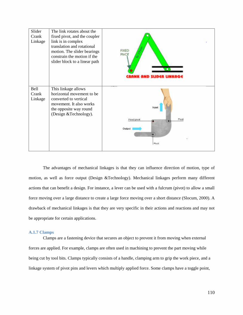
110
Slider
Crank
Linkage
The link rotates about the
fixed pivot, and the coupler
link is in complex
translation and rotational
motion. The slider bearings
constrain the motion if the
slider block to a linear path
Bell
Crank
Linkage
This linkage allows
horizontal movement to be
converted to vertical
movement. It also works
the opposite way round
(Design &Technology).
The advantages of mechanical linkages is that they can influence direction of motion, type of
motion, as well as force output (Design &Technology). Mechanical linkages perform many different
actions that can benefit a design. For instance, a lever can be used with a fulcrum (pivot) to allow a small
force moving over a large distance to create a large force moving over a short distance (Slocum, 2000). A
drawback of mechanical linkages is that they are very specific in their actions and reactions and may not
be appropriate for certain applications.
A.1.7 Clamps
Clamps are a fastening device that secures an object to prevent it from moving when external
forces are applied. For example, clamps are often used in machining to prevent the part moving while
being cut by tool bits. Clamps typically consists of a handle, clamping arm to grip the work piece, and a
linkage system of pivot pins and levers which multiply applied force. Some clamps have a toggle point,

111
and once this point is passed, it has entered a locked position. The clamp will not unlock unless the
operator releases the linkage.
There are five main types of toggle clamps that are most frequently used: vertical handle,
horizontal handle, straight line action, latch type and squeeze action. The handles of vertical and
horizontal handle toggle clamps are in these positions when clamped. Straight line action type toggles use
a moving plunger that slides along its axis and pushes or pulls to load. Latch type clamps use a hook or
U-bolt as the clamping arm and are usually applied to closure mechanisms. Squeeze action clamps use a
pinching force to hold parts together (Toggle Clamps Advantages and Comparison, n.d.).
Figure 12A Types of Clamps, 2016, retrieved from http://www.jwwinco.com/products/section15 Copy Right J.W. Winco, Inc. ©
2016
The main advantages of using toggle-action clamps are their ability to quickly clamp and release,
move completely clear of the workpiece, as well as their high
ratio of clamping force to actuation force (Lantrip, 2003).
Clamping force is the force applied to the work piece. Clamping
force depends on multiple factors such as spindle position and
height, spindle cushioning, as well as the material of the piece
and the mechanical advantage of the clamp. (Toggle Clamps,
n.d.). In general, an operator can physically apply about 1/3 of
Figure 13A Toggle Action Clamp, 2016, retrieved
from http://www.steelsmith-
clamps.eu/toggle_action_force_factors Copy
Right 2016 Anemo Engineering bvba

112
Figure 14A Swedish Lifting Device, APILIFT, retrieved
fromhttp://www.lpsbiodling.se/sv/artiklar/redskap/apilift
-professional-apl02m.html
the stated holding capacity when applied by hand with medium effort. There are some disadvantages, as
toggle clamps have a very limited range of motion and are unable to compensate for varying thicknesses
within the work piece.
Clamps can be applied to lifting devices in
various ways. Some devices use clamping force to hold
the item while it is in motion. An example of this can be
seen in Figure 14A. The clamp is tightened through the
use of a lever arm operated by hand. The toggle clamp
can enter a locked position, preventing the clamping
force from weakening.
A.1.8 Gearheads
A gearhead is a mechanical device that increases the torque of a gear mechanism and
implementing one into a design has many benefits. When mounted to the shaft of the motor output,
gearheads provide a mechanical advantage defined by a ratio. For example if a motor can generate 100 lb-
in of torque, by adding a 4:1 gearhead, it can generate a torque of 400 lb-in. Gearheads also decrease
output speeds; finding a proper gearhead for an application tends to be a compromises between output
speed and torque values. Using the same gear ratio, a motor running at 1,000 rpm will output 250 rpm.
Due to the fact that many motors are not efficient at low speeds, increasing input speeds improves system
performance. A gearhead’s ability to reduce speed and increase torque allow smaller motors and drives to
be used in the system, ultimately cutting costs.
There are various types of gear heads, with different benefits and applications as seen in Table 12.

113
Table 12 Types of Gears
Type Advantages Disadvantages
Spur gears
Most common type of
gear. Have straight teeth
and transmit motion and
power between parallel
shafts
Compact
Cost effective
High gear ratios
Noisy
Prone to wear due to
teeth running
perpendicular to gear
face
Worm- gear
Simple gears used for
right angle output
High precision
Low noise
Low maintenance
Various configurations
Low efficiency
Nonreversible
Planetary
Drives surrounding
“planetary” gears by a
central “sun” gear.
Planetary gears ride
within a ring gear which
rotates the output shaft.
Compact Size
High efficiency
Low backlash
High torque-weight
ratio
Complex
Costly
Cycloidal
Use input shaft to drive
eccentric bearing, which
in turn drives cycloidal
disc. Output shaft has
rollers that fit into holes
within the disc.
High ratios
Small in size
Increased Vibrations
due to cycloidal motion
Wear on disc teeth
Source: The Benefits of Gearboxes
Engineers must determine what type of configuration is appropriate for their design. There are
two main types of gear heads and each are used depending on the output needed as well as design space.
In-line gear heads have an output shaft that is centered, or “in-line” with the motor shaft, allowing higher
torque output, low backlash and typically lower costs than right angle types. With right-angle gear heads,
the output shaft is at 90° to the driving shaft of the motor. One benefit of these gearheads is that they fit
into tight spaces.

114
A.2 Anthropometric Data

115

116

117
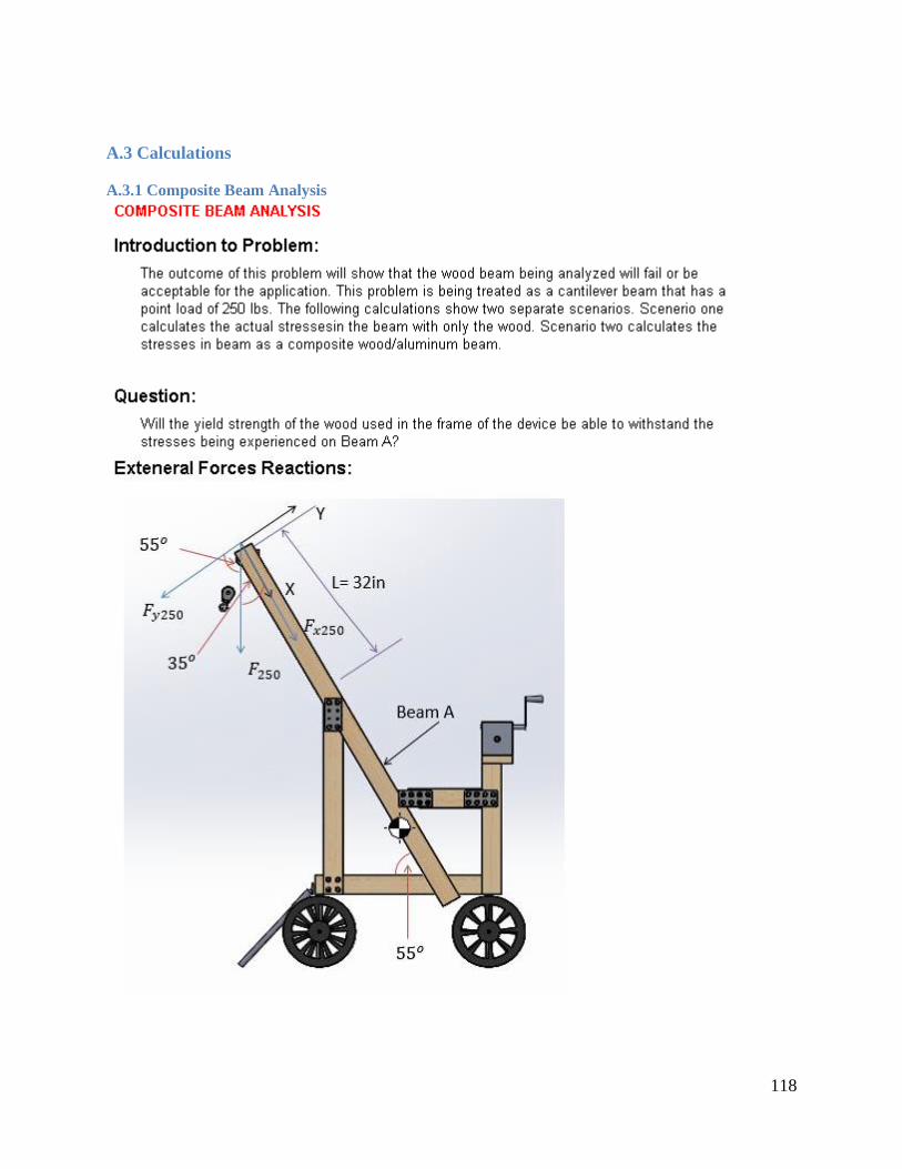
118
A.3 Calculations
A.3.1 Composite Beam Analysis

119

120

121

122

123

124
A.3.2 Double Fixed Pulley Beam Analysis

125
A.3.3 Tipping Analysis

126

127
A.4 Assembly Instructions for Cart

128

129

130

131

132


![Bee-hive[2x2x2] Bee-hive[3x3x3] Bee-hive[4x3x4]dagagu.godohosting.com/pdf/bt234.pdf · 2017-01-03 · 이상 ‘3축 커넥터 ’의 연결 시스템 이였습니다 Bee-hive 조립을](https://static.fdocuments.net/doc/165x107/5fa1ec2632ebc505ed281764/bee-hive2x2x2-bee-hive3x3x3-bee-hive4x3x4-2017-01-03-f-a3-e.jpg)