Bedienungsanleitung Präzisionsthermometer purchasing a Sensor GGO/GGA/GOO xxx, a sensor element is...
14
H84.0.14.6C-01 GHM Messtechnik GmbH - Standort Greisinger Hans-Sachs-Str. 26 • D-93128 Regenstauf +49 (0) 9402 / 9383-0 +49 (0) 9402 / 9383-33 [email protected] As of Version 1.0 Operating Manual GMH 5690 WEEE-Reg.-Nr. DE 93889386 Waterproof Oxygen Meter for Oxygen in Gases With Integrated Temperature and Pressure Measuring Please carefully read these instructions before use! Please consider the safety instructions! Please keep for future reference!
Transcript of Bedienungsanleitung Präzisionsthermometer purchasing a Sensor GGO/GGA/GOO xxx, a sensor element is...

H84.0.14.6C-01
GHM Messtechnik GmbH - Standort Greisinger Hans-Sachs-Str. 26 • D-93128 Regenstauf
+49 (0) 9402 / 9383-0 +49 (0) 9402 / 9383-33 [email protected]
As of Version 1.0 Operating Manual GMH 5690
WEEE-Reg.-Nr. DE 93889386
Waterproof Oxygen Meter for Oxygen in Gases
With Integrated Temperature and Pressure Measuring
Please carefully read these instructions before use!
Vor Inbetriebnahme aufmerksam lesen!
Please consider the safety instructions! Beachten Sie die Sicherheitshinweise!
Please keep for future reference! Zum späteren Gebrauch aufbewahren!

H84.0.14.6C-01 Operating Manual GMH 5690 page 2 of 14 _____________________________________________________ _____________________________________________________________________________
Contents 1 GENERAL NOTE ...................................................................................................................................................... 3
2 SAFETY ...................................................................................................................................................................... 3
2.1 INTENDED USE ....................................................................................................................................................... 3 2.2 SAFETY SIGNS AND SYMBOLS ................................................................................................................................ 3 2.3 SAFETY GUIDELINES .............................................................................................................................................. 3
3 PRODUCT DESCRIPTION ...................................................................................................................................... 4
3.1 SCOPE OF SUPPLY .................................................................................................................................................. 4 3.2 OPERATION AND MAINTENANCE ADVICE .............................................................................................................. 4
4 START OF OPERATION ......................................................................................................................................... 4
5 OPERATION .............................................................................................................................................................. 5
5.1 DISPLAY ELEMENTS ............................................................................................................................................... 5 5.2 PUSHBUTTONS ....................................................................................................................................................... 5 5.3 CONNECTIONS ....................................................................................................................................................... 6 5.4 POP-UP CLIP ........................................................................................................................................................... 6
6 OXYGEN MEASURING IN GASES- PLEASE NOTE ......................................................................................... 7
6.1 CHOICE OF SENSING ELEMENTS ............................................................................................................................ 7 6.2 APPLICATION OF THE DIFFERENT SENSOR TYPES GGO ..., GOO ... AND GGA ..................................................... 7
7 CALIBRATION OF THE SENSOR......................................................................................................................... 8
7.1 ONE POINT CALIBRATION ('(AL 1-PT') ................................................................................................................... 8
7.2 2 / 3-POINT CALIBRATION ('(AL 2-PT, (AL 3-PT') .................................................................................................. 8
7.3 EVALUATION OF SENSOR STATE (ELE[) ................................................................................................................ 8
7.4 CALIBRATION INTERVAL ([.INT) ............................................................................................................................ 9
8 CONFIGURATION ................................................................................................................................................... 9
9 REPLACING BATTERIES .................................................................................................................................... 11
10 ALARM (“AL.”) ................................................................................................................................................... 11
11 ADJUSTMENT OF TEMPERATURE INPUT ................................................................................................. 11
12 INSPECTION OF THE ACCURACY / ADJUSTMENT SERVICES ............................................................ 11
13 UNIVERSAL OUTPUT ....................................................................................................................................... 12
13.1 INTERFACE ....................................................................................................................................................... 12
14 ERROR AND SYSTEM MESSAGES ................................................................................................................ 13
15 RESHIPMENT AND DISPOSAL ....................................................................................................................... 14
15.1 RESHIPMENT .................................................................................................................................................... 14 15.2 DISPOSAL INSTRUCTIONS ................................................................................................................................. 14
16 SPECIFICATION ................................................................................................................................................. 14

H84.0.14.6C-01 Operating Manual GMH 5690 page 3 of 14 _____________________________________________________ _____________________________________________________________________________
1 General Note
Read this document carefully and get used to the operation of the device before you use it. Keep this document within easy reach near the device for consulting in case of doubt.
Mounting, start-up, operating, maintenance and removing from operation must be done by qualified, specially trained staff that have carefully read and understood this manual before starting any work.
The manufacturer will assume no liability or warranty in case of usage for other purpose than the intended one, ignoring this manual, operating by unqualified staff as well as unauthorized modifications to the device. The manufacturer is not liable for any costs or damages incurred at the user or third parties because of the usage or application of this device, in particular in case of improper use of the device, misuse or malfunction of the connection or of the device.
The manufacturer is not liable for misprints.
2 Safety
2.1 Intended Use The instrument is measuring oxygen in air and gas mixtures either as partial pressure or as concentration in %vol. For the measuring an external sensor of the type GOO-... or GGO... has to be connected to the 7-pole bayonet socket. Due to the properties of the sensor, it has to be calibrated regularly (e.g. at fresh air = 20.95%) to get precise values. If the sensor is used up, this will be detected during the calibration, the sensor has to be regenerated or replaced before continuing with measuring.
The safety requirements (see below) have to be observed. The device must be used only according to its intended purpose and under suitable conditions. Use the device carefully and according to its technical data (do not throw it, strike it, …) Protect the device from dirt.
2.2 Safety signs and symbols Warnings are labeled in this document with the followings signs:
Caution! This symbol warns of imminent danger, death, serious injuries and significant damage to property at non-observance.
Attention! This symbol warns of possible dangers or dangerous situations which can provoke damage to the device or environment at non-observance.
Note! This symbol point out processes which can indirectly influence operation or provoke unforeseen reactions at non-observance.
2.3 Safety guidelines This device has been designed and tested in accordance with the safety regulations for electronic devices. However, its trouble-free operation and reliability cannot be guaranteed unless the standard safety measures and special safety advises given in this manual will be adhered to when using the device.
1. Trouble-free operation and reliability of the device can only be guaranteed if the device is not subjected to any other climatic conditions than those stated under "Specification". If the device is transported from a cold to a warm environment condensation may cause in a failure of the function. In such a case make sure the device temperature has adjusted to the ambient temperature before trying a new start-up.

H84.0.14.6C-01 Operating Manual GMH 5690 page 4 of 14 _____________________________________________________ _____________________________________________________________________________
2. If there is a risk whatsoever involved in running it, the device has to be switched off immediately and to be marked accordingly to avoid re-starting. Operator safety may be a risk if: - there is visible damage to the device - the device is not working as specified - the device has been stored under unsuitable conditions for a longer time. In case of doubt, please return device to manufacturer for repair or maintenance.
3. When connecting the device to other devices the connection has to be designed most thoroughly as internal connections in third-party devices (e.g. connection GND with protective earth) may lead to undesired voltage potentials that can lead to malfunctions or destroying of the instrument and the connected devices.
4. Do not use these products as safety or emergency stop devices or in any other application where failure of the product could result in personal injury or material damage. Failure to comply with these instructions could result in death or serious injury and material damage.
5. This device must not be used at potentially explosive areas! The usage of this device at potentially explosive areas increases danger of deflagration, explosion or fire due to sparking.
3 Product Description
3.1 Scope of supply The scope of supply includes:
Handheld instrument GMH 5690 with 2 AAA-Batteries (oxygen sensor usually is ordered separately. For choice please refer to chapter 6.1and 6.2)
Operating manual
Short form manual
3.2 Operation and maintenance advice
1. Battery operation: If ‘bAt’ is shown in the lower display the battery has been used up and needs to be replaced. However, the device will operate correctly for a certain time. If ‘bAt’ is shown in the upper display the voltage is too low to operate the device; the battery has been completely used up. Battery change: p.r.t. chapter 9.
The battery has to be taken out, when storing device above 50°C. We recommend taking out battery if device is not used for a longer period of time. After recommissioning the real-time clock has to be set again.
2. Treat device and sensor carefully. Use only in accordance with above specification. (do not throw, hit against etc.). Protect plug and socket from soiling.
3. USB or mains operation: When connecting a mains cable or USB interface cable, please take care to connect only allowed components.
The output voltage of a connected power supply unit has to be between 4.5 and 5.5 V DC. Don’t apply overvoltage!
We recommend operation with interface cable USB 5100. Then device is supplied by the USB interface of the connected PC or USB power supply adapter.
4 Start of Operation Connect sensor, switch instrument on with .
After the segment test the instrument shows „[ORR“ shortly, if it was user adjusted. The device starts measurement afterwards.

H84.0.14.6C-01 Operating Manual GMH 5690 page 5 of 14 _____________________________________________________ _____________________________________________________________________________
5 Operation
5.1 Display elements
1
Main display:
Oxygen concentration in % (% O2 Vol) or
Oxygen partial pressure (hPa or mmHg)
(choice via -key)
2
Secondary display: sensor temperature or absolute pressure (alternating, please refer to
chapter 8 LcD.2))
3 Main display units
4 State of battery or sensor, if was pressed
5 Shows, if minimum/maximum/ memorized measuring value is in display
6 OK: Signals, if oxygen and temperature is stable
7 CAL: Signals, if automatic calibration is in progress
8 Pressure unit of internal sensor
5.2 Pushbuttons
On / off key, backlight
press shortly: activate backlight or switch on instrument press longer: switch off instrument
Set / Menu:
press shortly: Change oxygen display unit
press for 2 sec. (menu): invoke configuration menu
min / max:
press shortly: min. or max. value is displayed
press for 2 sec: the corresponding value is deleted
Configuration (please refer to chapter 8):
enter values, or change settings
cal:
press shortly: display of sensor state rating
press for 2 sec: start sensor calibration
store/Enter:
with Auto-Hold off: hold and save current measuring value (‘HLD’ is displayed) with Auto-Hold on: start new measuring, It is finished , when “HLD’ shows in display please refer to chapter 8 Configuration (please refer to chapter 8): confirm settings, return to measuring

H84.0.14.6C-01 Operating Manual GMH 5690 page 6 of 14 _____________________________________________________ _____________________________________________________________________________
5.3 Connections
Universal output: interface, supply, analog output (see chapter 13)
7-pole bayonet socket: connection for sensor and temperature probe
5.4 Pop-up clip Handling:
• Pull at label “open” in order to swing open the pop-up clip.
• Pull at label “open” again to swing open the pop-up clip further.
Pop-up clip closed
Pop-up clip at position 90°
Pop-up clip at position 180°
Function:
• The device with a closed pop-up clip can be plainly laid onto a table or attached to a belt, etc.
• The device with pop-up clip at position 90° can be set up on a table, etc.
• The device with pop-up clip at position 180° can be suspended from a screw or the magnetic holder GMH 1300.
Device attached to a belt
Device set up on a table
Device suspended from
magnetic holder GMH 1300

H84.0.14.6C-01 Operating Manual GMH 5690 page 7 of 14 _____________________________________________________ _____________________________________________________________________________
6 Oxygen Measuring in Gases- Please Note The GMH 369x is designed for measuring the oxygen partial pressure or the oxygen concentration (%vol, calculated from partial pressure and ambient pressure) in gases. Please keep in mind:
The sensor hast o calibrated regularly, e.g. at fresh ambient air The calibration and the measuring are pressure depending!
The instrument automatically measures the ambient pressure, be sure, that instruments pressure is the same like the pressure at the sensors membrane. For the full automatic compensation a precision pressure sensor is integrated in the instrument.
The sensor temperature has to be the same like the gas temperature! Temperature differences may falsify the results! Please have in mind that temperature adoption of the sensor and the air may take several hours. A suitable ventilation or gas flow around the sensor would speed up this process significantly.
The sensor consists of a sensing element (GOEL xxx) enclose in a sensor housing (GGO/ GGA/GOO). When purchasing a Sensor GGO/GGA/GOO xxx, a sensor element is already integrated, e.g. a GGO 570: contains housing GGO and a sensor element GOEL 370.
6.1 Choice of Sensing Elements
GOEL 370: Universal sensor element with special protection measures especially for diving application (“Nitrox”). Very long life time, also suitable for applications with larger CO2 concentrations.
GOEL 380: Fast responding for low oxygen concentration e.g. protection atmosphere below 1%, max 25%. For applications without larger CO2 concentrations.
Sensors are not allowed to used in „under-Water-Diving-Application (e.g. Rebreather) DANGER
6.2 Application of the different sensor types GGO ..., GOO ... and GGA
GGO (closed sensor)
For measurements at atmosphere and in systems without over or under pressure the GGO... is sufficient. Additionally the GGO can be screwed tightly into systems with small over or under pressure. Attention! Mind the maximum pressure and the maximum pressure difference at the membrane.
If instrument and sensor pressure are different, it will be compensated wrong!
GOO 370 / 380 (open sensor)
The sensor is equipped with drillings at the end and because of its special construction the measuring gas streams optimally around the sensor. No pressure can appear while gas blows to the sensor, which otherwise would result in erroneous measures. The temperature compensation speed of the sensor also is optimised by this design. Especially the measuring of gases from compressed gas bottles, where the expansion of the gas leaving the bottle lowers the temperature, is optimised with regard to the temperature compensation and pressure errors. The gas flow should be chosen in a suitable range, where no overpressure can happen, esp. if the sensor is connected directly to the source e.g. by means of a tube.
GGA (closed sensor with pressure port): Not suitable for GMH 3692

H84.0.14.6C-01 Operating Manual GMH 5690 page 8 of 14 _____________________________________________________ _____________________________________________________________________________
7 Calibration of the Sensor In order to compensate for ageing of the sensor, the sensor has to be calibrated at regular intervals. The device is equipped with an easy-to-use calibration functions. We recommend to calibrate the sensor at least all 7 days, or for maximum precision, before each measuring series.
7.1 One Point Calibration ('(AL 1-PT') The calibration adjusts the sensor to the oxygen content of the atmosphere (20.95%). Therefore simply expose the sensor to the ambient air (sufficient ventilation in closed rooms has to be ensured)
Start calibration: press -key for 2 seconds
The display will show 'A,R , and as soon the values for oxygen and temperature are stable, the calibration will be finished Then the sensor state resulting of the successful calibration will be shown for a short time (evaluation in 10%
steps: xx% ELE[).
7.2 2 / 3-Point Calibration ('(AL 2-PT, (AL 3-PT') The sensor will be automatically calibrated to the oxygen content of the atmosphere (20.95%) and one or two additional concentrations. As reference gases usually Nitrogen (0% vol O2) or pure oxygen are used
1. Start calibration: press -key for 2 seconds 2. First calibration reference: (Pt.1)
As first reference at a 3-point calibration, the zero reference has to be applied (NULL), at a 2-point calibration
either 100% or 0%(NULL).
The display will show , and the referring reference which should be applied:
- NULL for 0% oxygen
- 0.2 for pure oxygen As long as the display blinks, no valid reference is recognised by the instrument. As soon the values for oxygen and temperature are stable, the calibration of the first point will be finished. The instrument tells you to apply the next reference (possible references are blinking in the display).
3. Second calibration reference: (Pt.2)
The display will show , and the referring reference which should be applied:
- A,R for ambient air
- 0.2 for pure oxygen
- NULL for 0% oxygen As long as the display blinks, no valid reference is recognised by the instrument. As soon the values for oxygen and temperature are stable, the calibration of the second point will be finished. At 2-point calibration the calibration will be finished and the sensor state resulting of the successful
calibration will be shown for a short time (evaluation in 10% steps: xx% ELE[). At 3-point calibration the instrument tells you to apply the next reference (possible reference is blinking)
4. Third calibration reference: (Pt.3)
The display will show , and the referring reference which should be applied: As soon the values for oxygen and temperature are stable, the calibration of the second point will be finished. At 2-point calibration the calibration will be finished and the sensor state resulting of the successful
calibration will be shown for a short time (evaluation in 10% steps: xx% ELE[). In case of error messages being displayed during the calibration process, please refer to our notes at the end of this manual! If a calibration cannot be carried out after an extended period of time, at least one of the measuring values is unstable (oxygen partial pressure, temperature). Please check your measuring arrangements!
7.3 Evaluation of Sensor State (ELE[)
Watch sensor state: press key "CAL" shortly once display show for a short time xx% ELE[.
It will show the sensor state resulting of the last successful calibration carried out. The valuation is displayed in 10 percent steps: 100% means optimal sensor condition. Lower values are indicating that the sensor life time will be reached soon.
Remark: But also an erroneous pressure may be the cause of low valuation values.

H84.0.14.6C-01 Operating Manual GMH 5690 page 9 of 14 _____________________________________________________ _____________________________________________________________________________
7.4 Calibration Interval ([.INT) You can enter the interval after which the device reminds you to recalibrate in the configuration. The interval times should be chosen according to the application and the stability of the sensor. “CAL” flashes on the display as soon as the interval has expired.
8 Configuration
Some menu points depend on current device settings (e.g. some points are locked if logger memory contains data sets).
To change device’s settings, press “menu” for 2 seconds. This will activate the configuration menu
(main display: “SEt”). Pressing “menu” changes between the menus points, pressing jumps to the
referring parameters, which can be selected with key .
The parameter value can be changed with or .
Pressing “menu” again jumps back to the main configuration menu and saves the settings.
Pressing “enter” finishes the configuration.
Pressing “menu” and “store” at the same time for more than 2 seconds will reset the device to factory defaults.
If no key is pressed for more than 2 minutes the configuration will be aborted. All changes will be discarded!
Menu Parameter Value Description
or see
SET
(ONF
Set Configuration: General configuration
[H 2 P 02
hPa Oxygen partial pressure display in hPa *
P 02 mmHg Oxygen partial pressure display in mmHg
RES K , Best O2 resolutions
LO Low O2 resolution, calm value display (standard)
LCD.2 T Second. display always temperature
P Second. display always absolute pressure
P T Second. display alternates between temperature and abs. pressure
U N,T T
°C All temperatures in degree Celsius (ex works setting)
°F All temperatures in degree Fahrenheit
[AL.P 1-PT Simple one point calibration at air
2-PT / 3-PT 2 or 3- calibration at air and 0% (e.g. N2 ) or 100 %
[. INT 1 … 365 Calibration reminder period (in days)
OFF No calibration reminder
A VTO HLD
ON Auto measuring value identification Auto Hold (when logger = off)
OFF Standard hold function on key press (when logger = off)
P.OFF 1 … 120
Power-off delay in minutes. Device will be automatically switched off as soon as this time has elapsed if no key is pressed/no interface communication takes place. (ex works setting 20min)
OFF Automatic power-off function deactivated (continuous operation)
L,TE OFF
Background Illumination deactivated
5...120 Turn off illumination after 5… 120s (factory settings: 10 s)
ON Illumination always on
0V T OFF Interface off -> minimal power consumption
SER Serial interface activated (ex works setting)
ADR 0 1, 1 1,2 1, … 9 1 Base address for serial interface communication (ex works setting 01)

H84.0.14.6C-01 Operating Manual GMH 5690 page 10 of 14 _____________________________________________________ _____________________________________________________________________________
SET
(ORR
Set Corr: Input adjustment
0FFS °C or °F
-5.0 °C .. 5.0 °C or
-9.0 °F .. 9.0 °F
The zero point of the temperature measuring is shifted for the entered value. This can be used to compensate sensor and instrument deviations
OFF No zero adjustment for temperature measurement (=0.0°)
S[AL °C or °F
-5.00 ... 5.00 % The slope of the temperature measurement is corrected by this value.
This can be used to compensate sensor and instrument deviations
OFF No slope adjustment for temperature measurement (=0.00)
0FFS hPa
-20 .. 20 hPa The zero point of the pressure measuring is shifted for the entered value.
This can be used to compensate sensor deviations
OFF No zero adjustment for pressure measurement (=0 hPa)
SET
AL
Set Alarm
AL. 1 ON / NO.SO
Monitoring Oxygen: Alarm on with buzzer / Alarm on without buzzer
OFF No alarm monitoring for oxygen
AL.,N [ONC
Monitoring Oxygen: Concentration in %
P. 02 Monitoring Oxygen: Partial pressure in hPa or mmHg
A 1.LO e.g. 0.0..100.0 %
Min alarm limit oxygen (not if AL. 1. oFF)
A 1.H, e.g. 0.0..100.0 %
Max alarm limit oxygen (not if AL. 1. oFF)
AL. 2 ON / NO.SO
Temperature monitoring : Alarm on with buzzer / Alarm on without buzzer
OFF No alarm monitoring for temperature
A2.LO -5.0 ..+50.0 °C
Min alarm limit temperature (not if AL. 2. oFF)
A2.H, -5.0 ..+50.0 °C
Max alarm limit temperature (not if AL. 2. oFF)
H84.0.14.6C-01 Operating Manual GMH 5690 page 11 of 14 _____________________________________________________ _____________________________________________________________________________
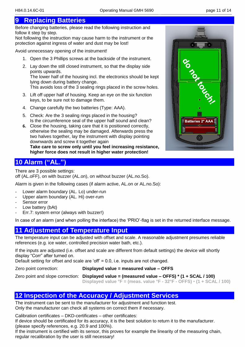
9 Replacing Batteries Before changing batteries, please read the following instruction and follow it step by step. Not following the instruction may cause harm to the instrument or the protection against ingress of water and dust may be lost!
Avoid unnecessary opening of the instrument!
1. Open the 3 Phillips screws at the backside of the instrument.
2. Lay down the still closed instrument, so that the display side points upwards. The lower half of the housing incl. the electronics should be kept lying down during battery change. This avoids loss of the 3 sealing rings placed in the screw holes.
3. Lift off upper half of housing. Keep an eye on the six function keys, to be sure not to damage them.
4. Change carefully the two batteries (Type: AAA).
5. Check: Are the 3 sealing rings placed in the housing? Is the circumference seal of the upper half sound and clean?
6. Close the housing, taking care that it is positioned correctly, otherwise the sealing may be damaged. Afterwards press the two halves together, lay the instrument with display pointing downwards and screw it together again Take care to screw only until you feel increasing resistance, higher force does not result in higher water protection!
10 Alarm (“AL.”)
There are 3 possible settings: off (AL.oFF), on with buzzer (AL.on), on without buzzer (AL.no.So).
Alarm is given in the following cases (if alarm active, AL.on or AL.no.So):
- Lower alarm boundary (AL. Lo) under-run - Upper alarm boundary (AL. Hi) over-rum - Sensor error - Low battery (bAt) - Err.7: system error (always with buzzer!)
In case of an alarm (and when polling the interface) the ‘PRIO’-flag is set in the returned interface message.
11 Adjustment of Temperature Input The temperature input can be adjusted with offset and scale. A reasonable adjustment presumes reliable references (e.g. ice water, controlled precision water bath, etc.).
If the inputs are adjusted (i.e. offset and scale are different from default settings) the device will shortly display “Corr” after turned on. Default setting for offset and scale are ‘off’ = 0.0, i.e. inputs are not changed.
Zero point correction: Displayed value = measured value – OFFS
Zero point and slope correction: Displayed value = (measured value – OFFS) * (1 + SCAL / 100) Displayed value °F = (meas. value °F - 32°F - OFFS) • (1 + SCAL / 100)
12 Inspection of the Accuracy / Adjustment Services The instrument can be sent to the manufacturer for adjustment and function test. Only the manufacturer can check all systems on correct them if necessary.
Calibration certificates – DKD-certificates – other certificates: If device should be certificated for its accuracy, it is the best solution to return it to the manufacturer. (please specify references, e.g. 20.9 and 100%). If the instrument is certified with its sensor, this proves for example the linearity of the measuring chain, regular recalibration by the user is still necessary!

H84.0.14.6C-01 Operating Manual GMH 5690 page 12 of 14 _____________________________________________________ _____________________________________________________________________________
13 Universal Output
The output can be used as serial interface (for USB5100 interface converter). If the output is not needed, it is strongly recommended to deactivate it (Out oFF) to lower power consumption. This increases battery life time. If the device is used together with interface adapter USB 5100 the device is supplied from the interface.
device pin assignment:
1: external supply +5V, 50mA
2: GND
3: TxD/RxD (3.3V Logic)
4: without function
Only suitable adaptor cables are permitted (accessories)!
13.1 Interface The following standard software packages are available: GSOFT3050: Operating and evaluation software for the integrated logger function EBS20M / -60M: 20-/60-channel software for measuring value display GMHKonfig: Configuration Software (for free on internet) In case you want to develop your own software we offer a GMH3000-development package including: a universally applicable Windows functions library ('GMH3x32e.DLL') with documentation, can be used
by all ‘established’ programming languages, suitable for: Windows XP™, Windows Vista™, Windows 7™, Windows 8™
Programming examples Visual Studio 2010 (C#, C++ and VB), Testpoint™, LabView™, etc.
The device has 4 channels: - oxygen concentration in % vol - oxygen partial pressure in hPa or mmHg - temperature value at the time of recording in °C or °F - absolute pressure in hPa abs or mmHg abs
Supported interface-functions:
1 2 3 4 Code Name/Function 1 2 3 4 Code Name/Function
x x x x 0 read nominal value x x x x 199 read measuring type in display
x x x x 3 read system status x x x x 200 read min. display range
x 12 read ID-no. x x x x 201 read max. display range
x x x 22 read min alarm limit x x x x 202 read unit of display
x x x 23 read max alarm limit x x x x 204 read decimal point of display
x x x x 176 read min. measuring range x 208 read channel count
x x x x 177 read max. measuring range x 222 read turn-off-delay
x x x x 178 read measuring range unit x 223 Set turn-off-delay
x x x x 179 read measuring range decimal point x 240 Reset
x x x x 180 read measuring type x 254 read program identification
The measuring and range values read via interface are always in the selected display
unit!

H84.0.14.6C-01 Operating Manual GMH 5690 page 13 of 14 _____________________________________________________ _____________________________________________________________________________
14 Error and System Messages Display Meaning Remedy
low battery voltage, device will continue to work for a short time
replace battery
If mains operation: wrong voltage replace power supply, if fault continues to exist: device damaged
low battery voltage replace battery
If mains operation: wrong voltage Check/replace power supply, if fault continues to exist: device damaged
No display or
weird display
Device does not react on keys
low battery voltage replace battery
If mains operation: wrong voltage check/replace power supply, if fault continues to exist: device damaged
system error disconnect battery or power supply, wait some time, re-connect
device defective return to manufacturer for repair
SENS
ERRO
sensor error: no sensor cable connected connect suitable sensor
Sensor, cable or instrument defect return to manufacturer for repair
ERR.1 Value exceeding measuring range Check: Is the value exceeding the specified
measuring range? ->value too high!
Wrong sensor connected Check sensor
Sensor, cable or instrument defect return to manufacturer for repair
ERR.2 Value below display range Check: Is the value below the specified
measuring range? ->value too low!
Wrong sensor connected Check sensor
Sensor, cable or instrument defect return to manufacturer for repair
ERR.7 system error return to manufacturer for repair
If “BAT“ is flashing, the battery will be exhausted soon. Further measurements are possible for short time.
If “BAT“ is displayed continuously the battery is ultimately exhausted and has to be replaced. Further measurements aren’t possible any more.
Messages During Calibration/Adjustment
>CAL< CAL flashing in
display
either preset calibration interval has expired or last calibration is not valid
device has to be calibrated!
[AL ERR.1 wrong reference point at air check sensor and reference gas
[AL ERR.2
slope too low
reference gas wrong check sensor and reference gas
sensor element is defect replace sensor element
[AL ERR.3
slope too high
reference gas wrong check sensor and reference gas
sensor element is defect replace sensor element
[AL ERR.4 incorrect calibration temperature calibration can only be done at 0…50 °C
[AL ERR.5 Zero value to low/negative
sensor element is defect replace sensor element
[AL ERR.6
zero value to high
reference gas wrong check sensor and reference gas
sensor element is defect replace sensor element
[AL ERR.7 incorrect calibration pressure check calibration pressure
[AL ERR.8 signal not stable / timeout check sensor and reference gas
[AL ERR.9 sensor not known: cannot be calibrated check sensor and wiring

H84.0.14.6C-01 Operating Manual GMH 5690 page 14 of 14 _____________________________________________________ _____________________________________________________________________________
15 Reshipment and Disposal
15.1 Reshipment All devices returned to the manufacturer have to be free of any residual of measuring media and
other hazardous substances. Measuring residuals at housing or sensor may be a risk for persons or environment
Use an adequate transport package for reshipment, especially for fully functional devices. Please make sure that the device is protected in the package by enough packing materials.
15.2 Disposal instructions
Batteries must not be disposed in the regular domestic waste but at the designated collecting points. The device must not be disposed in the unsorted municipal waste! Send the device directly to us (sufficiently stamped), if it should be disposed. We will dispose the device appropriate and environmentally sound.
16 Specification Measuring Ranges Oxygen concentration [Lo] 0.0 ... 100.0 % O2 (vol.)
[Hi] 0.00…100.00 % O2 (vol.) electrochemical sensors GGO / GOO
Oxygen partial pressure [Lo] -0 ... 1100 hPa O2 [Hi] -0.0 ... 1100.0 hPa O2
“ “ “
Sensor temperature -5.0 ... + 50.0 °C NTC 10k (integrated in GGO / GOO cable)
Absolute pressure 10 ... 1200 hPa abs. integrated pressure sensor Accuracy
(instrument without sensor, at 25°C, 1000 hPa abs)
Oxygen concentration ±0.1 % O2 (Vol)
Oxygen partial pressure ± 1 hPa
Sensor temperature ± 0.1 °C
Accuracy Absolute pressure 3 hPa or 0.1% of measured value (the higher one to be applied)
Working conditions -25 ... 50 °C; 0 ... 95 % r.H. (not condensing, sensor min -5°C)
Nom. temperature 25°C
Storage temp. -25 ... 70 °C (sensor min -5°C)
Connections O2 & temperature 6 pole waterproof bayonet connector
Interface / external supply
4 pole waterproof bayonet connector (USB adapter USB 5100)
Display LCD, white backlight, two 4½ digits 7-segment (main and auxiliary display) with additional symbols
Calibration automatic 1 -, 2- or 3-point calibration, 0%, 100% or ambient air (20.95%)
Alarm Buzzer / visual / interface 2 channels: selectable oxygen unit and temperature
Additional functions Min / max / hold / auto hold
Housing Housing
Break-proof ABS housing, incl. silicone protective cover
Protection class IP65 / IP67
Dimensions L*W*H [mm] 160 * 86 * 37 incl. silicone protective cover, approx. 250 g incl. battery and cover
Power supply 2*AAA battery (included in scope of supply) or external
Current consumption 0.9 mA (for Out = oFF, equivalent to 1000 h), backlight ~10mA (auto-off)
Battery indicator 4-stage battery state indicator, Change battery display for exhausted battery: “bAt”, warning: “bAt” flashing
Auto-off function Device will be automatically switched off if no key is pressed/no interface communication takes place for the time of the power-off delay. The power-off delay can be set to values between 1and 120 min.; it can be completely deactivated.
EMC The device corresponds to the essential protection ratings established in the Regulations of the Council for the Approximation of Legislation for the member countries regarding electromagnetic compatibility (2004/108/EG) Additional fault: <1%