
Bedienungsanleitung Operating Instructions MINICOMB...Bedienungsanleitung Operating Instructions...
36
Bedienungsanleitung Operating Instructions MINICOMB ® Serie Kompaktdruckschalter 30x30 Kompaktdruckschalter 30x30 / ATEX
Transcript of Bedienungsanleitung Operating Instructions MINICOMB...Bedienungsanleitung Operating Instructions...

BedienungsanleitungOperating Instructions
MINICOMB® SerieKompaktdruckschalter 30x30
Kompaktdruckschalter 30x30 / ATEX

MINICOMB® Serie Kompaktdruckschalter 30x30 Bedienungs- und Wartungsanleitung

MINICOMB® Serie Kompaktdruckschalter 30x30Bedienungs- und Wartungsanleitung
DE
UT
SCH
EN
GLI
SH
3
InhaltKapitel 1: Zu dieser Anleitung ............................................................................................4Kapitel 2: Zu Ihrer Sicherheit ..............................................................................................4Kapitel 3: Lieferumfang ........................................................................................................6Kapitel 4: Einsatzbereiche ....................................................................................................6Kapitel 5: Technische Daten MINICOMB Serie .............................................................8
Die angegebenen Daten dienen allein der Produktbeschreibung. Eine Aussa-ge über eine bestimmte Beschaffenheit oder eine Eignung für einen bestimm-ten Einsatzzweck kann aus unseren Angaben nicht abgeleitet werden. Die Angaben entbinden den Verwerter nicht von eigenen Prüfungen. Es ist zu beachten, dass unsere Produkte einem natürlichen Verschleiß- und Alterungs-prozess unterliegen.
© Alle Rechte bei PINTER Mess- und Regeltechnik GmbH, auch für den Fall von Schutzrechtsanmeldungen. Jede Verfügungsbefugnis, wie Kopie- und Weiter-gaberecht, bei uns.
Alle in diesem Katalog genannten Produktnamen, Produktbezeichnungen und Logos sind Warenzeichen und/oder eingetragene Warenzeichen und Eigen-tum der jeweiligen Rechteinhaber.CHEMSEAL, DIMIO, INDUSENS, INDUSWITCH, INTELLICOMB, MANOCOMB, MINICOMB sind Warenzeichen und/oder eingetragene Warenzeichen der PINTER Mess- und Regeltechnik GmbH und/oder verbunder Unternehmen in Deutschland, der Europäischen Union, Schweiz und/oder anderen Ländern.Die Verwendung von PINTER Warenzeichen ist ohne ausdrückliche Zustim-mung untersagt.
Auf der Titelseite sind Beispielkonfigurationen abgebildet. Das ausgelieferte Produkt kann daher von der Abbildung abweichen.
Diese Anleitung wurde in deutscher Sprache erstellt.
MINICOMB® Serie Kompaktdruckschalter 30x30 Bedienungs- und Wartungsanleitung
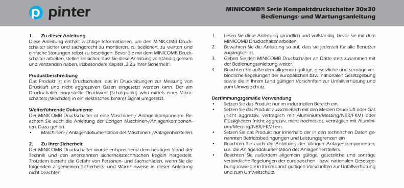
1. Lesen Sie diese Anleitung gründlich und vollständig, bevor Sie mit dem MINICOMB Druckschalter arbeiten.
2. Bewahren Sie die Anleitung so auf, dass sie jederzeit für alle Benutzer zugänglich ist.
3. Geben Sie den MINICOMB Druckschalter an Dritte stets zusammen mit der Bedienungsanleitung weiter.
4. Beachten Sie außerdem allgemein gültige, gesetzliche und sonstige ver-bindliche Regelungen der europäischen bzw. nationalen Gesetzgebung sowie die in Ihrem Land gültigen Vorschriften zur Unfallverhütung und zum Umweltschutz.
Bestimmungsgemäße Verwendung• Setzen Sie das Produkt nur im industriellen Bereich ein.• Setzen Sie das Produkt ausschließlich mit den Medien Druckluft oder Gas
(nicht aggressiv, verträglich mit Aluminium/Messing/NBR/FKM) oder Flüssigkeiten (nicht aggressiv, nicht hochviskos, verträglich mit Alumini-um/Messing/NBR/FKM) ein.
• Setzen Sie das Produkt nur innerhalb der in den technischen Daten ge-nannten Betriebsbedingungen und Leistungsgrenzen ein
• Beachten Sie auch die Anleitung der übrigen Anlagenkomponenten, u.a. die Anlagendokumentation des Anlagenherstellers.
• Beachten Sie außerdem allgemein gültige, gesetzliche und sonstige verbindliche Regelungen der europäischen bzw. nationalen Gesetzge-bung sowie die in Ihrem Land gültigen Vorschriften zur Unfallverhütung und zum Umweltschutz.
1. Zu dieser AnleitungDiese Anleitung enthält wichtige Informationen, um den MINICOMB Druck-schalter sicher und sachgerecht zu montieren, zu bedienen, zu warten und einfache Störungen selbst zu beseitigen. Bevor Sie mit dem MINICOMB Druck-schalter arbeiten, stellen Sie sicher, dass Sie diese Anleitung vollständig gelesen und verstanden haben, insbesondere Kapitel „2 Zu Ihrer Sicherheit“.
ProduktbeschreibungDas Produkt ist ein Druckschalter, das in Druckleitungen zur Messung von Druckluft und nicht aggressiven Gasen eingesetzt werden kann. Der am Druckschalter eingestellte Druckwert (Schaltpunkt) wird mittels eines Mikro-schalters (Wechsler) in ein elektrisches, binäres Signal umgesetzt.
Weiterführende DokumenteDer MINICOMB Druckschalter ist eine Maschinen-/ Anlagenkomponente. Be-achten Sie auch die Anleitung der übrigen Maschinen-/Anlagenkomponen-ten. Dazu gehört:• Maschinen- / Anlagendokumentation des Maschinen- /Anlagenherstellers
2. Zu Ihrer SicherheitDer MINICOMB Druckschalter wurde entsprechend dem heutigen Stand der Technik und den anerkannten sicherheitstechnischen Regeln hergestellt. Trotzdem besteht die Gefahr von Personen- und Sachschäden, wenn Sie die folgenden allgemeinen Sicherheits- und Warnhinweise in dieser Anleitung nicht beachten:

MINICOMB® Serie Kompaktdruckschalter 30x30Bedienungs- und Wartungsanleitung
DE
UT
SCH
EN
GLI
SH
5
• Belasten Sie das Gerät unter keinen Umständen mechanisch. Verwen-den Sie das Gerät niemals als Griff oder Stufe. Stellen Sie keine Gegen-stände darauf ab.
• Es dürfen keine Veränderungen oder Umbauten am Gerät vorgenom-men werden!
• Alle Tätigkeiten mit dem Produkt dürfen nur von einer Fachkraft oder von einer unterwiesenen Person unter der Leitung und Aufsicht einer Fachkraft erfolgen. Eine Fachkraft ist, wer aufgrund seiner fachlichen Ausbildung, seiner Kenntnisse und Erfahrungen, sowie seiner Kennt-nisse der einschlägigen Bestimmungen die ihm übertragenen Arbeiten beurteilen, mögliche Gefahren erkennen und geeignete Sicherheitsmaß-nahmen treffen kann. Eine Fachkraft muss die einschlägigen fachspezi-fischen Regeln einhalten. Beachten Sie auch mögliche weitere Anforde-rungen im Verwenderland.
• Schalten Sie immer den relevanten Teil der Anlage drucklos und span-nungsfrei, bevor Sie das Gerät montieren bzw. Stecker anschließen oder ziehen. Sichern Sie die Anlage gegen wiedereinschalten. Hängen Sie während der Montage Warnschilder an die Hauptschalter, die vor dem Wiedereinschalten warnen.
• Bei explosionsgeschützten Geräten sind die Installations- u. Wartungsbe-stimmungen für Ex-Geräte nach EN 60079-14, EN 60079-17 (CENELEC) sind zu beachten.
Der bestimmungsmäßige Gebrauch schließt auch ein, dass Sie diese Anleitung gelesen und verstanden haben.
Montage• Lassen Sie das Produkt vor der Montage und Inbetriebnahme einige
Stunden akklimatisieren, da sich ansonsten im Gehäuse Kondeswasser niederschlagen kann.
• Montieren und befestigen Sie das Produkt entsprechend der Darstel-lungen.
• Wenn das Produkt nicht ordnungsgemäß befestigt ist, können andere Anlagenteile durch unkontrollierte Bewegungen des Produkts beschä-digt, wie auch Personen verletzt werden. Stellen Sie sicher, dass das Produkt sicher befestigt ist.
Elektrischer Anschluss• Verlegen Sie die Leitungen so, dass niemand darüber stolpern kann.• Verwenden Sie ausschließlich harmonisierte (farb- bzw. nummern-
codierte) Leitungen. Achten Sie auf den korrekten Anschluss der Leitungen!
• Schliessen Sie das Produkt an entsprechend der Darstellungen. • Wenn das Produkt nicht ordnungsgemäß elektrisch angeschlossen ist,
kann die Schutzart nicht gewährleistet werden. Stellen Sie sicher, das der Stecker sicher angeschlossen ist.
MINICOMB® Serie Kompaktdruckschalter 30x30 Bedienungs- und Wartungsanleitung
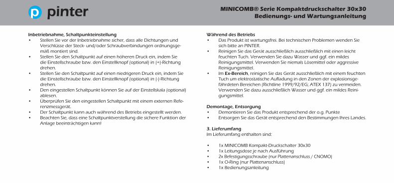
Inbetriebnahme, Schaltpunkteinstellung• Stellen Sie vor der Inbetriebnahme sicher, dass alle Dichtungen und
Verschlüsse der Steck- und/oder Schraubverbindungen ordnungsge-mäß montiert sind.
• Stellen Sie den Schaltpunkt auf einen höheren Druck ein, indem Sie die Einstellschraube bzw. den Einstellknopf (optional) in (+)-Richtung drehen.
• Stellen Sie den Schaltpunkt auf einen niedrigeren Druck ein, indem Sie die Einstellschraube bzw. den Einstellknopf (optional) in (-)-Richtung drehen.
• Den eingestellen Schaltpunkt können Sie auf der Einstellskala (optional) ablesen.
• Überprüfen Sie den eingestellen Schaltpunkt mit einem externen Refe-renzmessgerät.
• Der Schaltpunkt kann auch während des Betriebs eingestellt werden.• Beachten Sie, dass eine Schaltpunktverstellung die sichere Funktion der
Anlage beeinträchtigen kann!
Während des Betriebs• Das Produkt ist wartungsfrei. Bei technischen Problemen wenden Sie
sich bitte an PINTER.• Reinigen Sie das Gerät ausschließlich ausschließlich mit einen leicht
feuchten Tuch. Verwenden Sie dazu Wasser und ggf. ein mildes Reinigungsmittel. Verwenden Sie niemals Lösemittel oder aggressive Reinigungsmittel.
• Im Ex-Bereich, reinigen Sie das Gerät ausschließlich mit einem feuchten Tuch um elektrostatische Aufladung in den Zonen der explosionsge-fährdeten Bereichen (Richtline 1999/92/EG; ATEX 137) zu vermeiden. Verwenden Sie dazu ausschließlich Wasser und ggf. ein mildes Reini-gungsmittel.
Demontage, Entsorgung• Demontieren Sie das Produkt entsprechend der o.g. Punkte• Entsorgen Sie das Gerät entsprechend den Bestimmungen Ihres Landes.
3. LieferumfangIm Lieferumfang enthalten sind:
• 1x MINICOMB Kompakt-Druckschalter 30x30• 1x Leitungsdose je nach Ausführung• 2x Befestigungsschraube (nur Plattenanschluss / CNOMO)• 1x O-Ring (nur Plattenanschluss)• 1x Bedienungsanleitung

MINICOMB® Serie Kompaktdruckschalter 30x30Bedienungs- und Wartungsanleitung
DE
UT
SCH
EN
GLI
SH
7
4. EinsatzbereicheDer MINICOMB ist ein Druckschalter, der in Druckleitungen zur Messung von Druckluft und nicht aggressiven Gasen eingesetzt werden kann. Soweit mit den medienberührten Teilen kompatibel kann der MINICOMB auch für Flüssigkeiten und aggressiven Medien eingesetzt werden.Der am Druckschalter eingestellte Druckwert (Schaltpunkt) wird mittels eines Mikroschalters (Wechsler) in ein elektrisches, binäres Signal umgesetzt.
Der MINICOMB ist geeignet für die Bildung sicherheitstechnischer Funktionen nach ISO13849 mit der Einstufung PLc.
Darüberhinaus kann der MINICOMB als ATEX-Version in explosionsgefährde-ter Umgebung der Zonen 2 bzw. 22 eingesetzt werden und ist zugelassen nach ATEX-Richtlinie:ATEX-Richtlinie: II 3G Ex nA nC IIC T4 GcATEX-Richtlinie: II 3D Ex tc IIIC T135°C Dc
MINICOMB® Serie Kompaktdruckschalter 30x30 Bedienungs- und Wartungsanleitung
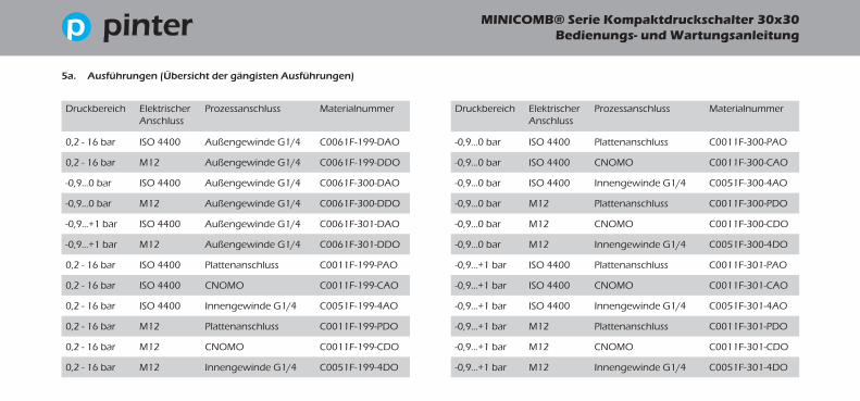
5a. Ausführungen (Übersicht der gängisten Ausführungen)
Druckbereich Elektrischer Anschluss
Prozessanschluss Materialnummer
0,2 - 16 bar ISO 4400 Außengewinde G1/4 C0061F-199-DAO
0,2 - 16 bar M12 Außengewinde G1/4 C0061F-199-DDO
-0,9...0 bar ISO 4400 Außengewinde G1/4 C0061F-300-DAO
-0,9...0 bar M12 Außengewinde G1/4 C0061F-300-DDO
-0,9...+1 bar ISO 4400 Außengewinde G1/4 C0061F-301-DAO
-0,9...+1 bar M12 Außengewinde G1/4 C0061F-301-DDO
0,2 - 16 bar ISO 4400 Plattenanschluss C0011F-199-PAO
0,2 - 16 bar ISO 4400 CNOMO C0011F-199-CAO
0,2 - 16 bar ISO 4400 Innengewinde G1/4 C0051F-199-4AO
0,2 - 16 bar M12 Plattenanschluss C0011F-199-PDO
0,2 - 16 bar M12 CNOMO C0011F-199-CDO
0,2 - 16 bar M12 Innengewinde G1/4 C0051F-199-4DO
Druckbereich Elektrischer Anschluss
Prozessanschluss Materialnummer
-0,9...0 bar ISO 4400 Plattenanschluss C0011F-300-PAO
-0,9...0 bar ISO 4400 CNOMO C0011F-300-CAO
-0,9...0 bar ISO 4400 Innengewinde G1/4 C0051F-300-4AO
-0,9...0 bar M12 Plattenanschluss C0011F-300-PDO
-0,9...0 bar M12 CNOMO C0011F-300-CDO
-0,9...0 bar M12 Innengewinde G1/4 C0051F-300-4DO
-0,9...+1 bar ISO 4400 Plattenanschluss C0011F-301-PAO
-0,9...+1 bar ISO 4400 CNOMO C0011F-301-CAO
-0,9...+1 bar ISO 4400 Innengewinde G1/4 C0051F-301-4AO
-0,9...+1 bar M12 Plattenanschluss C0011F-301-PDO
-0,9...+1 bar M12 CNOMO C0011F-301-CDO
-0,9...+1 bar M12 Innengewinde G1/4 C0051F-301-4DO

MINICOMB® Serie Kompaktdruckschalter 30x30Bedienungs- und Wartungsanleitung
DE
UT
SCH
EN
GLI
SH
9
Druckbereich Elektrischer Anschluss
Prozessanschluss Materialnummer
0,2 - 16 bar 3m Kabel Plattenanschluss C0211F-199-PFO
0,2 - 16 bar 3m Kabel Innengewinde G1/4 C0251F-199-4FO
0,2 - 16 bar 5m Kabel Plattenanschluss C0211F-199-PGO
0,2 - 16 bar 5m Kabel Innengewinde G1/4 C0251F-199-4GO
0,2 - 16 bar 7m Kabel Plattenanschluss C0211F-199-PHO
0,2 - 16 bar 7m Kabel Innengewinde G1/4 C0251F-199-4HO
-0,9...0 bar 3m Kabel Plattenanschluss C0211F-300-PFO
-0,9...0 bar 3m Kabel Innengewinde G1/4 C0251F-300-4FO
-0,9...0 bar 5m Kabel Plattenanschluss C0211F-300-PGO
-0,9...0 bar 5m Kabel Innengewinde G1/4 C0251F-300-4GO
-0,9...0 bar 7m Kabel Plattenanschluss C0211F-300-PHO
-0,9...0 bar 7m Kabel Innengewinde G1/4 C0251F-300-4HO
5b. ATEX-Ausführungen (Übersicht der gängisten Ausführungen)
Druckbereich Elektrischer Anschluss
Prozessanschluss Materialnummer
-0,9...+1 bar 3m Kabel Plattenanschluss C0211F-301-PFO
-0,9...+1 bar 3m Kabel Innengewinde G1/4 C0251F-301-4FO
-0,9...+1 bar 5m Kabel Plattenanschluss C0211F-301-PGO
-0,9...+1 bar 5m Kabel Innengewinde G1/4 C0251F-301-4GO
-0,9...+1 bar 7m Kabel Plattenanschluss C0211F-301-PHO
-0,9...+1 bar 7m Kabel Innengewinde G1/4 C0251F-301-4HO

MINICOMB® Serie Kompaktdruckschalter 30x30 Bedienungs- und Wartungsanleitung
5c. Technische Daten
Funktion mechanischer Druckschalter; Kraft-Waage-Messsystem mit Balgsensor
Lebensdauer mindestens 10 Mio Lastwechsel
Druckbereich (Einstellbereich) 0,2 - 16 bar
Vakuumbereiche (Einstellbereich) -0,9 - 0 bar
Druck-/Vakuumbereich (Einstellbereich) -0,9...+1 bar
Überdrucksicherheit 25 bar
Vakuumsicherheit -1 bar
Werkstoff Gehäuse Aluminium, trowalisiert
Werkstoff mediumberührte Teile Aluminium, Messing
Werkstoff mediumberührte Dichtungen FKM
Zulässige Mediumstemperatur -10...+80°C
Zulässige Umgebungstemperatur -20...+80°C
Temperaturabweichung ca. 1% je 20°C
Schaltkontakt 1 Mikroschalter (Wechsler)
Einstellgenauigkeit des Kontakts < 1,0% FS
Schaltgenauigkeit < 1,0% FS
Wiederholgenauigkeit < 1,0% FS
MINICOMB® Serie Kompaktdruckschalter 30x30Bedienungs- und Wartungsanleitung
DE
UT
SCH
EN
GLI
SH
11
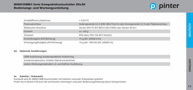
Schaltdifferenz (Hysterese) < 4,0% FS
Prozessanschluss Außengewinde G1/4 (DIN 3852 Form E) oder Innengewinde G1/4 oder Plattenanschluss
Elektrischer Anschluss Stecker EN175 301-803-A (ISO 4400) oder Stecker M12x1
Gewicht ca. 150 g
Schutzart IP65 (bzw. IP67 mit M12 Stecker)
Schockfestigkeit (XYZ-Richtung) 15 g (IEC 60068-2-64)
Schwingungsfestigkeit (XYZ-Richtung) 10 g (60 - 500 Hz) (IEC 60068-2-6)
OEM Ausführung; kundenspezifische Ausführung
Sondermessbereiche; erhöhte Überdrucksicherheit
andere Dichtungsmaterialien; öl- und fettfreie Ausführung
5d. Optionale Ausführungen
5e. Zubehör / AnbauteileEventuell wird Ihr MINICOMB Druckschalter mit Zubehör und/oder Anbauteilen geliefert. Prüfen Sie in diesem Fall auch die technischen Unterlagen und/oder Bedienungsanleitung dieser Komponenten.
MINICOMB® Serie Kompaktdruckschalter 30x30 Bedienungs- und Wartungsanleitung
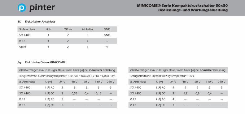
5f. Elektrischer Anschluss
El. Anschluss +Ub Öffner Schließer GND
ISO 4400 1 2 3 GND
M 12 1 2 4 ---
Kabel 1 2 3 4
Schaltvermögen max. zulässiger Dauerstrom I max [A] bei ohmscher Belastung
Bezugschaltzahl: 30/min; Bezugstemperatur: +30°C
El. Anschluss U [V] 24 V 48 V 60 V 110 V 240 V
ISO 4400 I [A] AC 5 5 5 5 5
ISO 4400 I [A] DC 3 1,2 0,8 0,4 ---
M 12 I [A] AC 4 --- --- --- ---
M 12 I [A] DC 3 --- --- --- ---
5g. Elektrische Daten MINICOMB
Schaltvermögen max. zulässiger Dauerstrom I max [A] bei induktiver Belastung
Bezugschaltzahl: 30/min; Bezugstemperatur: +30°C; AC = cos ϕ ca. 0,7°; DC = L/R ca 10ms
El. Anschluss U [V] 24 V 48 V 60 V 110 V 240 V
ISO 4400 I [A] AC 3 3 3 3 3
ISO 4400 I [A] DC 2 0,55 0,4 0,15 ---
M 12 I [A] AC 3 --- --- --- ---
M 12 I [A] DC 2 --- --- --- ---

MINICOMB® Serie Kompaktdruckschalter 30x30Bedienungs- und Wartungsanleitung
DE
UT
SCH
EN
GLI
SH
13
Schaltvermögen max. zulässiger Dauerstrom I max [A] bei ohmscher Belastung
Bezugschaltzahl: 30/min; Bezugstemperatur: +30°C
El. Anschluss U [V] 24 V 48 V 60 V 110 V 240 V
Kabel I [A] AC 3 3 3 3 3
Kabel I [A] DC 3 1,2 0,8 0,4 ---
5h. Elektrische Daten MINICOMB ATEX Ausführung
Schaltvermögen max. zulässiger Dauerstrom I max [A] bei induktiver Belastung
Bezugschaltzahl: 30/min; Bezugstemperatur: +30°C; AC = cos ϕ ca. 0,7°; DC = L/R ca 10ms
El. Anschluss U [V] 24 V 48 V 60 V 110 V 240 V
Kabel I [A] AC 3 3 3 3 3
Kabel I [A] DC 2 0,55 0,4 0,15 ---
MINICOMB® Serie Kompaktdruckschalter 30x30 Bedienungs- und Wartungsanleitung
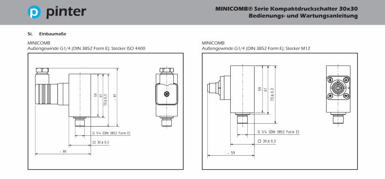
5i. Einbaumaße
MINICOMBAußengewinde G1/4 (DIN 3852 Form E); Stecker ISO 4400
MINICOMBAußengewinde G1/4 (DIN 3852 Form E); Stecker M12
MINICOMB® Serie Kompaktdruckschalter 30x30Bedienungs- und Wartungsanleitung
DE
UT
SCH
EN
GLI
SH
15
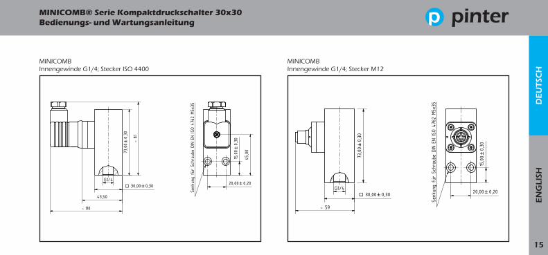
MINICOMBInnengewinde G1/4; Stecker ISO 4400
MINICOMBInnengewinde G1/4; Stecker M12

MINICOMB® Serie Kompaktdruckschalter 30x30 Bedienungs- und Wartungsanleitung
MINICOMBPlattenanschluss; Stecker ISO 4400
MINICOMBPlattenanschluss; Stecker M12

MINICOMB® Serie Kompaktdruckschalter 30x30Bedienungs- und Wartungsanleitung
DE
UT
SCH
EN
GLI
SH
17
MINICOMB ATEX-AusführungInnengewinde G1/4; Kabel
MINICOMB ATEX-AusführungPlattenanschluss; Kabel

MINICOMB® Series Compact Pressure Switch 30x30 Operating Instructions

DE
UT
SCH
EN
GLI
SH
19
MINICOMB® Series Compact Pressure Switch 30x30 Operating Instructions
ContentsChapter 1: About these instructions ............................................................................. 30Chapter 2: For your safety ................................................................................................ 30Chapter 3: Scope of supply .............................................................................................. 32Chapter 4: Application ...................................................................................................... 32Chapter 5: Technical data MANOCOMB Series ........................................................ 34
All given data for information purposes only. A statement about a specific con-dition or fitness for a particular purpose cannot be derived from this informati-on. This information does not absolve the user from making their own tests. It is to be taken into consideration that our products are subject to natural wear and aging process.
© All rights reserved for PINTER Mess- und Regeltechnik GmbH, also in case of patent applications.
All mentioned product names, product designations, product descriptions and logos are trademarks and property of their respective owners.CHEMSEAL, DIMIO, INDUSENS, INDUSWITCH, INTELLICOMB, MANOCOMB, MINICOMB are trademarks and/or registered trademarks of the PINTER Mess- und Regeltechnik GmbH and/or their affiliated companies in Germany, the European Union, Switzerland and/or other countries.
The use of PINTER trademarks is prohibited if not agreed otherwise.
Example configurations are shown on the front page. The supplied product may differ from the pictured products.
This document was originally issued in German language.
MINICOMB® Series Compact Pressure Switch 30x30 Operating Instructions
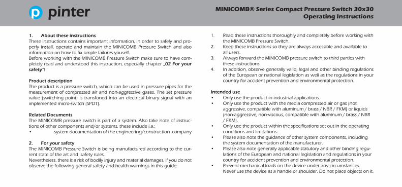
1. Read these instructions thoroughly and completely before working with the MINICOMB Pressure Switch.
2. Keep these instructions so they are always accessible and available to all users.
3. Always forward the MINICOMB pressure switch to third parties with these instructions.
4. In addition, observe generally valid, legal and other binding regulations of the European or national legislation as well as the regulations in your country for accident prevention and environmental protection.
Intended use• Only use the product in industrial applications.• Only use the product with the media compressed air or gas (not
aggressive, compatible with aluminum / brass / NBR / FKM) or liquids (non-aggressive, non-viscous, compatible with aluminum / brass / NBR / FKM).
• Only use the product within the specifications set out in the operating conditions and limitations.
• Please also note the guidance of other system components, including the system documentation of the manufacturer.
• Please also note generally applicable statutory and other binding regu-lations of the European and national legislation and regulations in your country for accident prevention and environmental protection.
• Prevent mechanical loads on the device under any circumstances. Never use the device as a handle or shoulder. Do not place objects on it.
1. About these instructionsThese instructions contains important information, in order to safely and pro-perly install, operate and maintain the MINICOMB Pressure Switch and also information on how to fix simple failures youself.Before working with the MINICOMB Pressure Switch make sure to have com-pletely read and understood this instruction, especially chapter „02 For your safety“!
Product descriptionThe product is a pressure switch, which can be used in pressure pipes for the measurement of compressed air and non-aggressive gases. The set pressure value (switching point) is transfoned into an electrical binary signal with an implemented micro-switch (SPDT).
Related DocumentsThe MINICOMB pressure switch is part of a system. Also take note of instruc-tions of other components and/or systems, these include i.a.:• system documentation of the engineering/construction company
2. For your safetyThe MINICOMB Pressure Switch is being manufactured according to the cur-rent state of the art and safety rules. Nevertheless, there is a risk of bodily injury and material damages, if you do not observe the following general safety and health warnings in this guide:
DE
UT
SCH
EN
GLI
SH
21
MINICOMB® Series Compact Pressure Switch 30x30 Operating Instructions
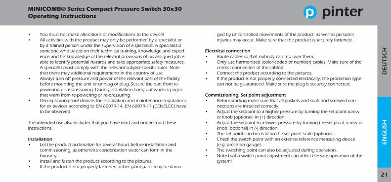
• You must not make alterations or modifications to the device!• All activities with the product may only be performed by a specialist or
by a trained person under the supervision of a specialist. A specialist is someone who based on their technical training, knowledge and experi-ence and his knowledge of the relevant provisions of his assigned job is able to identify potential hazards and take appropriate safety measures. A specialist must comply with the relevant subject-specific rules. Note that there may additional requirements in the country of use.
• Always turn off pressure and power of the relevant part of the facility before mounting the unit or unplug or plug. Secure the part from re-powering or re-pressuring. During installation hang out warning signs that warn from re-powering or re-pressuring.
• On explosion proof devices the installation and maintenance regulations for ex devices according to EN 60079-14, EN 60079-17 (CENELEC) have to be observed
The intended use also includes that you have read and understood these instructions.
Installation• Let the product acclimatize for several hours before installation and
commissioning, as otherwise condensation water can form in the housing.
• Install and fasten the product according to the pictures.• If the product is not properly fastened, other plant parts may be dama-
ged by uncontrolled movements of the product, as well as personal injuries may occur. Make sure that the product is securely fastened.
Electrical connection• Route cables so that nobody can trip over them.• Only use harmonized (color-coded or number) cables. Make sure of the
correct connection of the cables!• Connect the product accurding to the pictures. • If the product is not properly connected electrically, the protection type
can not be guaranteed. Make sure the plug is securely connected.
Commissioning, Set point adjustment• Before starting make sure that all gaskets and seals and screwed con-
nections are installed correctly. • Adjust the setpoint to a higher pressure by turning the set point screw
or knob (optional) in (+) direction.• Adjust the setpoint to a lower pressure by turning the set point screw or
knob (optional) in (-) direction.• The set point can be read on the set point scale (optional).• Check the switch point with an external reference measuring device
(e.g. precision gauge).• The switching point can also be adjusted during operation.• Note that a switch point adjustment can affect the safe operation of the
system!

MINICOMB® Series Compact Pressure Switch 30x30 Operating Instructions
During operation• The product is maintenance free. In case of technical problems, please
contact PINTER.• Clean the product with a slightly damp cloth only. Use water and if
necessary a mild detergent. Never use solvents or abrasive cleaners or aggressive cleaners.
• In hazardous area, clean only with a slightly moist cloth to prevent electrostatic charge within ignition endangered areas (Directive 1999/92/EC ATEX 137), use only water and if necessary a mild deter-gent.
Disposal• Dismount the product according to the steps above.• Dispose of the device according to the regulations of your country.
3. Scope of deliveryThe delivery includes:
• 1x MINICOMB compact pressure switch 30x30• 1x connector depending on version• 2x fixing screws (only sub-base mounting / CNOMO)• 1x O-Ring (only sub-base mounting)• 1x operating instructions
4. ApplicationThe MINICOMB is a pressure switch, which can be used in pressure pipes for the measurement of compressed air and non-aggressive gases. When compatible with the MINICOMB‘s wetted parts, it can also be used for liquids and aggressive media.The set pressure value (switching point) is transfoned into an electrical binary signal with an implemented micro-switch (SPDT) .
The MINICOMB is suitable for setting up safety-related systems according to ISO13849 with classification PLc.
Furthermore the MINICOMB in ATEX-version can be used in hazardous areas Zones 2 / 22. It is certified according to: ATEX-Directive: II 3G Ex nA nC IIC T4 GcATEX-Directive: II 3D Ex tc IIIC T135°C Dc

DE
UT
SCH
EN
GLI
SH
23
MINICOMB® Series Compact Pressure Switch 30x30 Operating Instructions

MINICOMB® Series Compact Pressure Switch 30x30 Operating Instructions
5a. Standard versions (most common versions)
pressure range
electrical connection
process connection
part number
0,2 - 16 bar ISO 4400 1/4“ male C0061F-199-DAO
0,2 - 16 bar M12 1/4“ male C0061F-199-DDO
-0,9...0 bar ISO 4400 1/4“ male C0061F-300-DAO
-0,9...0 bar M12 1/4“ male C0061F-300-DDO
-0,9...+1 bar ISO 4400 1/4“ male C0061F-301-DAO
-0,9...+1 bar M12 1/4“ male C0061F-301-DDO
0,2 - 16 bar ISO 4400 sub-base mounting C0011F-199-PAO
0,2 - 16 bar ISO 4400 CNOMO C0011F-199-CAO
0,2 - 16 bar ISO 4400 1/4“ female C0051F-199-4AO
0,2 - 16 bar M12 sub-base mounting C0011F-199-PDO
0,2 - 16 bar M12 CNOMO C0011F-199-CDO
0,2 - 16 bar M12 1/4“ female C0051F-199-4DO
pressure range
electrical connection
process connection
part number
-0,9...0 bar ISO 4400 sub-base mounting C0011F-300-PAO
-0,9...0 bar ISO 4400 CNOMO C0011F-300-CAO
-0,9...0 bar ISO 4400 1/4“ female C0051F-300-4AO
-0,9...0 bar M12 sub-base mounting C0011F-300-PDO
-0,9...0 bar M12 CNOMO C0011F-300-CDO
-0,9...0 bar M12 1/4“ female C0051F-300-4DO
-0,9...+1 bar ISO 4400 sub-base mounting C0011F-301-PAO
-0,9...+1 bar ISO 4400 CNOMO C0011F-301-CAO
-0,9...+1 bar ISO 4400 1/4“ female C0051F-301-4AO
-0,9...+1 bar M12 sub-base mounting C0011F-301-PDO
-0,9...+1 bar M12 CNOMO C0011F-301-CDO
-0,9...+1 bar M12 1/4“ female C0051F-301-4DO

DE
UT
SCH
EN
GLI
SH
25
MINICOMB® Series Compact Pressure Switch 30x30 Operating Instructions
pressure range
electrical connection
process connection
part number
0,2 - 16 bar 3m Kabel sub-base mounting C0211F-199-PFO
0,2 - 16 bar 3m Kabel 1/4“ female C0251F-199-4FO
0,2 - 16 bar 5m Kabel sub-base mounting C0211F-199-PGO
0,2 - 16 bar 5m Kabel 1/4“ female C0251F-199-4GO
0,2 - 16 bar 7m Kabel sub-base mounting C0211F-199-PHO
0,2 - 16 bar 7m Kabel 1/4“ female C0251F-199-4HO
-0,9...0 bar 3m Kabel sub-base mounting C0211F-300-PFO
-0,9...0 bar 3m Kabel 1/4“ female C0251F-300-4FO
-0,9...0 bar 5m Kabel sub-base mounting C0211F-300-PGO
-0,9...0 bar 5m Kabel 1/4“ female C0251F-300-4GO
-0,9...0 bar 7m Kabel sub-base mounting C0211F-300-PHO
-0,9...0 bar 7m Kabel 1/4“ female C0251F-300-4HO
5b. ATEX-versions (most common versions)
pressure range
electrical connection
process connection
part number
-0,9...+1 bar 3m Kabel sub-base mounting C0211F-301-PFO
-0,9...+1 bar 3m Kabel 1/4“ female C0251F-301-4FO
-0,9...+1 bar 5m Kabel sub-base mounting C0211F-301-PGO
-0,9...+1 bar 5m Kabel 1/4“ female C0251F-301-4GO
-0,9...+1 bar 7m Kabel sub-base mounting C0211F-301-PHO
-0,9...+1 bar 7m Kabel 1/4“ female C0251F-301-4HO
MINICOMB® Series Compact Pressure Switch 30x30 Operating Instructions
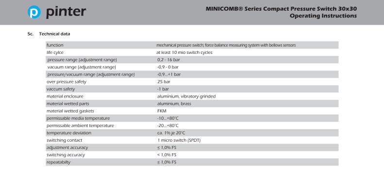
5c. Technical data
function mechanical pressure switch; force balance measuring system with bellows sensors
life cylce at least 10 mio switch cycles
pressure range (adjustment range) 0,2 - 16 bar
vacuum range (adjustment range) -0,9 - 0 bar
pressure/vacuum range (adjustment range) -0,9...+1 bar
over pressure safety 25 bar
vaccum safety -1 bar
material enclosure aluminium, vibratory grinded
material wetted parts aluminium, brass
material wetted gaskets FKM
permissable media temperature -10...+80°C
permissable ambient temperature -20...+80°C
temperature deviation ca. 1% je 20°C
switching contact 1 micro switch (SPDT)
adjustment accuracy < 1,0% FS
switching accuracy < 1,0% FS
repeatabilty < 1,0% FS

DE
UT
SCH
EN
GLI
SH
27
MINICOMB® Series Compact Pressure Switch 30x30 Operating Instructions
switching differential (hysteresis) < 4,0% FS
process connection 1/4“ male (DIN 3852 Form E) or 1/4“ female or sub-base mounting
electrical connection plug EN175 301-803-A (ISO 4400) or plug M12x1 or cable
weight approx. 150 g
protection IP65 (IP67 with M12 plug)
shock resistance (XYZ-direction) 15 g (IEC 60068-2-64)
vibration resistance (XYZ-direction) 10 g (60 - 500 Hz) (IEC 60068-2-6)
OEM version; customer specific versions
special scales and units; extended overpressure safety
special materials/seals; cleaned for O2 service
5d. Options
5e. AccessoriesYour MINICOMB pressure switch may be supplied with accessories.In this case, also check the technical documentation and / or operating instructions of these components.

MINICOMB® Series Compact Pressure Switch 30x30 Operating Instructions
5f. Electrical connection
+Ub NC NO GND
ISO 4400 1 2 3 GND
M 12 1 2 4 ---
cable 1 2 3 4
max. permissable steady current I max [A] - ohmic load
reference switch cycle: 30/min; reference temperature: +30°C
U [V] 24 V 48 V 60 V 110 V 240 V
ISO 4400 I [A] AC 5 5 5 5 5
ISO 4400 I [A] DC 3 1,2 0,8 0,4 ---
M 12 I [A] AC 4 --- --- --- ---
M 12 I [A] DC 3 --- --- --- ---
5g. Electrical data MINICOMB
max. permissable steady current I max [A] - inductive load
reference switch cycle: 30/min; reference temperature: +30°C; AC = cos ϕ ca. 0,7°; DC = L/R ca 10ms
U [V] 24 V 48 V 60 V 110 V 240 V
ISO 4400 I [A] AC 3 3 3 3 3
ISO 4400 I [A] DC 2 0,55 0,4 0,15 ---
M 12 I [A] AC 3 --- --- --- ---
M 12 I [A] DC 2 --- --- --- ---
DE
UT
SCH
EN
GLI
SH
29
MINICOMB® Series Compact Pressure Switch 30x30 Operating Instructions
max. permissable steady current I max [A] - ohmic load
reference switch cycle: 30/min; reference temperature: +30°C
El. Anschluss U [V] 24 V 48 V 60 V 110 V 240 V
Kabel I [A] AC 3 3 3 3 3
Kabel I [A] DC 3 1,2 0,8 0,4 ---
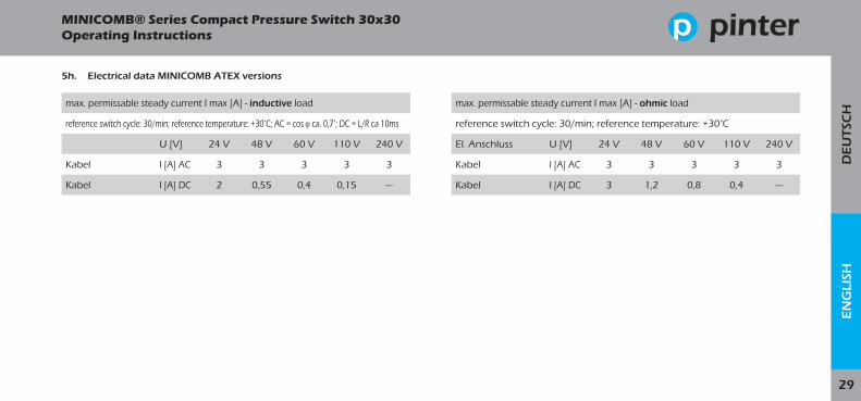
5h. Electrical data MINICOMB ATEX versions
max. permissable steady current I max [A] - inductive load
reference switch cycle: 30/min; reference temperature: +30°C; AC = cos ϕ ca. 0,7°; DC = L/R ca 10ms
U [V] 24 V 48 V 60 V 110 V 240 V
Kabel I [A] AC 3 3 3 3 3
Kabel I [A] DC 2 0,55 0,4 0,15 ---
MINICOMB® Series Compact Pressure Switch 30x30 Operating Instructions
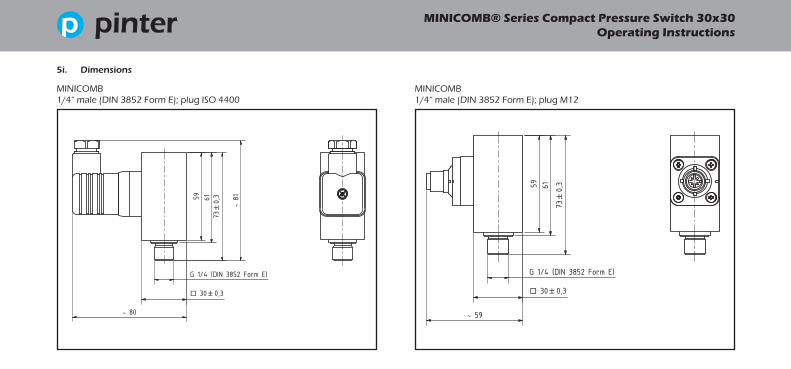
5i. Dimensions
MINICOMB1/4“ male (DIN 3852 Form E); plug ISO 4400
MINICOMB1/4“ male (DIN 3852 Form E); plug M12

DE
UT
SCH
EN
GLI
SH
31
MINICOMB® Series Compact Pressure Switch 30x30 Operating Instructions
MINICOMB1/4“ female; plug; ISO 4400
MINICOMB1/4“ female; plug; M12

MINICOMB® Series Compact Pressure Switch 30x30 Operating Instructions
MINICOMBsub-base mounting; plug ISO 4400
MINICOMBsub-base mounting; plug M12

DE
UT
SCH
EN
GLI
SH
33
MINICOMB® Series Compact Pressure Switch 30x30 Operating Instructions
MINICOMB ATEX-Ausführung1/4“ female; plug; cable
MINICOMB ATEX-Ausführung1/4“ female; plug; cable

MINICOMB® Series Compact Pressure Switch 30x30 Operating Instructions
DE
UT
SCH
EN
GLI
SH
35
MINICOMB® Series Compact Pressure Switch 30x30 Operating Instructions

PINTER Mess- und Regeltechnik GmbHKraichgaublick 17Technologiepark Neckartal-Odenwald74847 Obrigheim, Deutschland
Phone +49-6262-92670-0Fax +49-6262-92670-99E-Mail [email protected] www.pinter-gmbh.com BA
.MIN
ICO
MB.
19R1
.DEE
N


