
Bearing Design of Thin Sheet Steel Screwed Connections
15
Missouri University of Science and Technology Missouri University of Science and Technology Scholars' Mine Scholars' Mine International Specialty Conference on Cold- Formed Steel Structures (1998) - 14th International Specialty Conference on Cold-Formed Steel Structures Oct 15th, 12:00 AM Bearing Design of Thin Sheet Steel Screwed Connections Bearing Design of Thin Sheet Steel Screwed Connections Colin A. Rogers Gregory J. Hancock Follow this and additional works at: https://scholarsmine.mst.edu/isccss Part of the Structural Engineering Commons Recommended Citation Recommended Citation Rogers, Colin A. and Hancock, Gregory J., "Bearing Design of Thin Sheet Steel Screwed Connections" (1998). International Specialty Conference on Cold-Formed Steel Structures. 1. https://scholarsmine.mst.edu/isccss/14iccfsss/14iccfsss-session9/1 This Article - Conference proceedings is brought to you for free and open access by Scholars' Mine. It has been accepted for inclusion in International Specialty Conference on Cold-Formed Steel Structures by an authorized administrator of Scholars' Mine. This work is protected by U. S. Copyright Law. Unauthorized use including reproduction for redistribution requires the permission of the copyright holder. For more information, please contact [email protected].
Transcript of Bearing Design of Thin Sheet Steel Screwed Connections

Missouri University of Science and Technology Missouri University of Science and Technology
Scholars' Mine Scholars' Mine
International Specialty Conference on Cold-Formed Steel Structures
(1998) - 14th International Specialty Conference on Cold-Formed Steel Structures
Oct 15th, 12:00 AM
Bearing Design of Thin Sheet Steel Screwed Connections Bearing Design of Thin Sheet Steel Screwed Connections
Colin A. Rogers
Gregory J. Hancock
Follow this and additional works at: https://scholarsmine.mst.edu/isccss
Part of the Structural Engineering Commons
Recommended Citation Recommended Citation Rogers, Colin A. and Hancock, Gregory J., "Bearing Design of Thin Sheet Steel Screwed Connections" (1998). International Specialty Conference on Cold-Formed Steel Structures. 1. https://scholarsmine.mst.edu/isccss/14iccfsss/14iccfsss-session9/1
This Article - Conference proceedings is brought to you for free and open access by Scholars' Mine. It has been accepted for inclusion in International Specialty Conference on Cold-Formed Steel Structures by an authorized administrator of Scholars' Mine. This work is protected by U. S. Copyright Law. Unauthorized use including reproduction for redistribution requires the permission of the copyright holder. For more information, please contact [email protected].

Fourteenth International Specialty Conference on Cold-Formed Steel Structures S1. Louis, Missouri U.S.A., October 15-16,1998
BEARING DESIGN OF TIllN SHEET STEEL SCREWED CONNECTIONS
Colin A. Rogers! and Gregory J. Hancock2
SUMMARY
The 1996 Australian / New Zealand AS/NZS 4600 and North American; CSA-S136, AISI Cold Fonned Steel Design Standards allow for the use of thin (t < 0.9 mm in AS/NZS 4600), high strength ify = 550 MPa) sheet steels if the yield stress and ultimate strength are reduced to 75% of their minimum specified values. At present, these reduced material properties must be used in the design of screwed connections which undergo bearing and bearing/tilting failure. Previous research has illustrated the need for design standards to include a gradated bearing coefficient method to account for the behaviour of thin high strength sheet steels, instead of a gross reduction in material properties. This paper provides a summary of results detailing the behaviour of screwed connections tested in shear which have failed in the bearing· and bearing/tilting modes. Recommendations concerning the adequacy of current design standards with respect to a proposed fonnulation which can be used to more accurately predict the shear resistance of screwed connections which fail in the bearing and bearing/tilting modes are presented.
1 INTRODUCTION
Cold fonned structural members are fabricated from sheet steels consisting of various material properties which must meet the requirements prescribed in applicable national design standards. The Australian / New Zealand Standard for cold fonned steel structures AS/NZS 4600 (SA/SNZ, 1996) allows for the use of thin (t < 0.9 mm), high strength (h = 550 MPa) sheet steels in all structural sections. However, due to the low ductility exhibited by sheet steels which are cold reduced to thickness the engineer must use a yield stress and ultimate strength limited to 75% of the minimum specified values. The American Iron and Steel Institute (AISI) Design Specification (AlSl, 1997a) further limits the use of thin, high strength steels to roofing, siding and floor decking panels. Sheet steels are required to have a minimum elongation capability to ensure that members and connections can undergo small displacements without a loss in structural perfonnance, and to reduce the harmful effects of stress concentrations. The ductility criterion specified in the Australian / New Zealand and North American Design Standards (CSA, 1994; AlSl, 1997a) is based on an investigation of sheet steels by Dhalla and Winter (1974a,b) which did not include the thin, high strength G550 sheet steels available today. The G550 sheet steels used for this research must be differentiated from other sheet steels whose high yield stress and ultimate strength values are obtained by means of an alloying process, i.e. high strength low alloy (HSLA) steels. Note: An earlier paper by Rogers and Hancock (1997a) provides infonnation on the ductility of G550 and G300 sheet steels as used for the tests discussed in this paper. More detailed infonnation on these screwed connection tests of thin G550 and G300 sheet steels can be found in Rogers and Hancock ( 1997b). Rogers and Hancock recommended that the bearing coefficient for single overlap screwed connections contained in the Australian / New Zealand (SAlSNZ, 1996) and USA (AlS], 1997a)
1 Ph.D. Res. Student, Dept. of Civ. Engrg., Univ. of Sydney, Australia. 2 BHP Steel Prof. of Steel Struct., D.ept. of Civ. Engrg., Univ. of Sydney, Australia.
481

482
Design Standards is unconservative for thin sheet steels and test results warrant that a gradated bearing coefficient be used in design.
This paper reports on a proposed modification to the existing design fonnulation for single overlap screwed conrtections loaded in shear. A gradated bearing coefficient method is evaluated and calibrated using the test results of single overlap screwed connections concentrically loaded in shear, and fabricated using G550 and G300 sheet steels (see AS 1397 (1993)). Sheet steels which range in base metal thickness from 0.42-2.94 mm were included, where the type, number and orientation of screws were varied. The results of additional screwed connection specimens, mainly composed of single point fasteners, which were tested by the Australian Commonwealth Scientific and Industrial Research Organisation (CSIRO) Division of Building, Construction and Engineering (Macindoe and Pham, 1995, 1996), are also included as data for this paper.
2 COLD FORMED STEEL SCREWED CONNECTION DESIGN PROVISIONS
An overview of the design equations used for the prediction of bearing, as well as combined bearing/tilting connection capacity is provided in this section. The design bearing capacity per screw for connections regardless of the design standard used is as follows,
(1)
where C is a variable bearing coefficient. The Australian / New Zealand (SAlSNZ, 1996) and USA (AISI, 1997a) Design Standards require that c= 2.7 for shear connections, whereas the European Design Standard (E.uTOcode, 1996) requires that C = 2.1. In the Canadian Design Standard (CSA, 1994) C represents the stability of the hole edge based on the ratio of screw diameter to sheet
Table 1 Factor C, for Bearing Resistance (CSA, 199,4) d/t C dJt::; 10 1O<dJt<15 dJt> 15
3 30 tid 2
thickness, as listed in Table 1. The Australian / New Zealand and USA Design Standards specify that for a single shear connection where tz / tl :0; 1.0 and the two sheets are in contact at the screw position, the nominal bearing capacity is taken as the smaller of (2)-(4).
~ = 4.2~(t;d)f.z (2)
Vb = 2.7t1dful
~ = 2.7tzdfuz
(3)
(4)
where (2) is a tilting fonnulation, tl andful are the thickness and ultimate strength of the member in contact with the screw head, and t2 and fuz are the thickness and ultimate strength of the member not in contact with the screw head.
For a single shear connection where t2 / tl 2:: 2.5 and the twp sheets are in contact at the screw position, the nominal bearing capacity is taken as the smaller of the following:
Vb = 2.7t1dfu1 (5)
~ = 2.7tzdfu2 (6)
For a screw connection where 1.0 < t2 / tl < 2.5 and the two sheets are in contact at the screw position, the nominal bearing capacity is calculated from a linear interpolation between the minimum value obtained from (2)-(4) and the minimum value obtained from (5) and (6). Only the Australian / New Zealand (SAlSNZ, 1996) and USA (AISI, 1997a) Design Standards allow for
483
screwed connections where the thinner material is not in contact with the head of the screw. The Canadian Design Standard (CSA, 1994) provides an alternative formula to predict the
nominal tilting resistance based on the combined thickness of the connected sheets, where the thinner material, t1, is assumed to be in contact with the head of the screw.
Br = C (t1 + t2) d !o1 /4 (7)
The European Design Standard (Eurocode, 1996) includes a combined formulation of bearing and tilting where the thinner material, t1. is also assumed to be in contact with the head of the screw. This differs from the Australian / New Zealand (SAlSNZ, 1996) and USA (AlS1, 1997a) Design Standards where the material which is not in contact with the head of the screw, t2, is used in the tilting formula (see (2)).
Fb,Rd = afud t1
where a is defined as follows;
ift1 = t2
ift22::2.5 t1
a = 3.2-JtJ/d :,; 2.1
a= 2.1
If t1 < t2:'; 2.5 t1 then a is obtained by linear interpolation between (9) and (10).
3 SCREWED CONNECTION TEsT SPECIMENS
3.1 General
(8)
(9)
(10)
The results of screwed connection tests by Rogers and Hancock (1997b), as well as by Macindoe and Pham (1995, 1996) have been used as a basis for comparison between the current design equations specified in the Australian / New Zealand (SAlSNZ, 1996), North American (CSA, 1994; AlSI, 1997a) and European (Eurocode, 1996) Cold Formed Steel Design Standards, as well as the proposed bearing formulation. The ultimate load, Put. and serviceability based loads, i.e. the maximum load at/or before a connection displacement of 3 mm, P3.Ot. specified in ECCS TC7 (1983), and a connection displacement of 6.35 mm, P6.35t. specified by the Research Council on Structural Connections (AlSC, 1988) and the American Institute of Steel Construction (1989, 1993) (see Rogers and Hancock ( 1997b)) were used in the comparison with predicted loads.
3.2 Rogers and Hancock
One hundred and fifty single overlap screwed connection specimens with multiple point fasteners were tested in shear at the University of Sydney. Five different sheet steels were used, including both G550 and G300 grades which ranged in base metal thickness from 0.42-1.00 mm. Connections were tested with various type, number and arrangement of screws. Eight types of HITEKS and STITCH screws were used for this project. Further information concerning the types of screw connection specimens, test procedures and detailed results for the data contained in this paper can be found in Rogers and Hancock (1997b).
3.3CSIRO
The Australian Commonwealth Scientific and Industrial Research Organisation (CSlRO) Division of Building, Construction and Engineering completed a series of reports on the performance of

484
single point fasteners used with light gauge sheet steel connections (Macindoe and Pham, 1995, 1996). A limited amount of test data from the CSIRO study was included in this paper to provide a comprehensive listing of available single overlap screwed connection tests composed of G550 sheet steels. This dati does not consist of all screwed tests completed by the CSIRO, only those which can be used to further understand the bearing and tilting behaviour of G550 sheet steels in shear connections. Of the 158 additional single overlap screw tests which were listed as having failed by either bearing or tilting, 146 were solely composed of G550 sheet steels and 12 were composed of a thinner G550 sheet steel with a thicker G250 sheet steel. For all additional tests the thinner sheet steel was placed adjacent to the screw head.
3.4 Possible Modes of Failure
Various modes of failure can occur in a single overlap screwed sheet steel connection including; gross cross-section yielding, net cross-section fracture, end pull-out, bearing, tilting, combined bearing/tilting and screw shear. Only connections which failed by bearing or combined bearing/tilting (see Fig. 1) were included as data for this paper. In a bearing failure, the screws remain perpendicular to the sheet steel and an initial pull out tear in the direction of load, with piling of the sheet steel in front of the screw is exhibited. Typically, sheet distortion occurs to a. greater extent in the thinner material. The mode of failure recorded for all but 12 of the screw
Fig. 1 Bearing and Bearing/Tilting Failure Patterns
connection tests included was a combination of bearing and tilting, due to; 1) the extreme thinness of the sheet steels used, and in some cases 2) the use of screw fasteners for which the threads do not extend up to the base of the screw head, i.e. a non-threaded shank is located directly below the screw head due to limitations in the manufacturing process. In the bearing/tilting failure mode the ultimate load is preceded by a tearing of the sheet steel in the direction of load with the associated piling of sheet steel in front of the fasteners, along with a tilting of the screws caused by the eccentric loading of the two sheets. Failure is caused by a build-up of axial tensile forces in the screw and bearing stresses in the sheet steel. The tilting forces result from the rotated position of the fastener with respect to the direction of load in the connection.
4 PROPOSED DESIGN PROVISIONS FOR SCREWED CONNECTIONS
4.1 Basis of the Proposed Method
A proposed method to accommodate for the change in bearing behaviour with sheet steel thickness, which relies on the ratio of screw diameter to sheet thickness, dlt, is presented in this
485
section. Significantly unconservative predictions of connection resistance obtained for certain test specimens have demonstrated a need for a variable bearing coefficient which is dependent on the stability of the edge of the screw hole. Unconservative predictions of connection capacity have been recorded for test specimens where two different thickness sheet steels are connected and loaded in shear, as shown for the test-to-predicted results calculated using the ASINZS 4600 (1996) and AlSI (1997a) Design Standards for the 0421060-G550 and 0421100-G550 tests, the 0421080-G550 and 0421100-G550 tests, as well as the 042-G550/294-G250 tests (Note: 0421060-G550 refers to a connection composed of a 0.42 mm G550 sheet steel placed adjacent to the screw head and a 0.60 mm G550 sheet steel attached below. When a connection specimen was composed of two different thickness sheet steels, the thinner sheet steel was placed adjacent to the screw head.) The screwed connection test specimens included in this paper which have two elements of the same thickness, all failed in a combined bearing/tilting mode and have acceptable test-to-predicted ratios (see Rogers and Hancock (1997b).
Macindoe and Pham (1996) tested a number of screwed connections where bearing failure was forced to occur because of a large differential in the thickness of the connected sheets, e.g., 042-G550/294-G250 tests. This behaviour differs from that exhibited for the majority of connections tested for this paper and by Macindoe and Pham, where failure was due to a combination of bearing and tilting. The connection resistance calculated for the screwed connection tests where bearing/tiling failure occurred is reasonably accurate. Hence, this proposed method includes the tilting fonnulation specified in both the ASINZS-4600 (1996) and AlSI (1997a) Design Standards. It also includes the gross yielding and net section fracture failure provisions contained in the CSA-S136 (1994) and Eurocode 3 (1996) Design Standards, Le., no stress reduction factor is used (see Rogers and Hancock (1997b).
4.0 <> 042-05501294-G250
35 0 075-05501294-0250 3.0
~ 2.S . ~ 2.0
1.5
1.0
0.5
'" lOO-G550/294-G250
0.0 -1<'---1------+---+----+----+-----< 4
eld
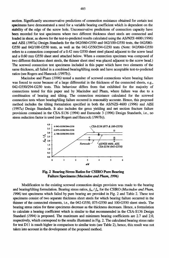
Fig. 2 Bearing Stress Ratios for CSIRO Pure Bearing Failure Specimens (Macindoe and Pham, 1996)
Modification to the existing screwed connection design provision was made to the bearing and bearing/tilting fonnulation. Bearing stress ratios, ibu I iu, for the CSIRO (Macindoe and Pham, 1996) test specimens which failed by pure bearing are provided in Fig. 2 and Table 2. These test specimens consist of two separate thickness sheet steels for which bearing failure occurred in the thinner of the connec.ted elements, i.e., the 042-G550, 075-G550 and 100-G550 sheet steels. The bearing stress ratios for these specimens decrease as the thickness decreases. Hence, a fonnulation to calculate a bearing coefficient which is similar to that recommended in the CSA-S136 Design Standard (1994) is proposed. The maximum and minimum bearing coefficients are 2.7 and 2.0, respectively, which correspond to the results illustrated in Fig. 2. The calculated bearing stress ratio for test D11 is much higher in comparison to similar tests (see Table 2), hence, this result was not taken into account in the development of the proposed method.

486
At present, the bearing coefficient contained in the AS/NZS-4600 (1996) and AISI (1997a) Design Standards is a constant 2.7 for screw connections. The Eurocode Design Standard (1996) also specifies a constant bearing coefficient of 2.1 for screwed connections. The CSA-S 136 Design Standard (1994) requires that the bearing coefficient vary depending on the ratio of dit, as shown in Fig. 3. The proposed method contains a variable bearing coefficient which is also dependent on dit, however, the maximum allowed value is lowered to 2.7 and the rate of change of the bearing coefficient is modified accordingly.
Table 2 Existing and Proposed Bearing Coefficients with CSIRO Bearin2 Failure Data (Macindoe and Pham 1996)
Specimen fb./fu eld
042-G5501294-G250 0176 1.93 5.31 DI77 2.19 5.31 0178 2.19 5.31 D182 2.04 3.18 0183 2.14 3.18 D184 2.38 3.18
075-G5501294-G250 D12 2.37 5.31 011 3.23 5.31 DI0 2.27 5.31
JOO-G5501294-G250 D92 2.74 4.00 D91 2.86 4.00 D90 2.72 4.00
Exist. Bearing Coefficients CSA- ASINZS
dlt S136 4600 AISI
11.2 2.68 2.7 11.2 2.68 2.7 11.2 2.68 2.7 11.2 2.68 2.7 11.2 2.68 2.7 11.2 2.68 2.7
6.28 3.00 2.7 6.28 3.00 2.7 6.28 3.00 2.7
6.25 3.00 2.7 6.25 3.00 2.7 6.25 3.00 2.7
CSA-SJ36 dit~ 10: C=3.0 10<dit< 15: C=30t/d dit'" 15: C=2.0
Euro-code
2.1 2.1 2.1 2.1 2.1 2.1
2.1 2.1 2.1
2.1 2.1 2.1
Proposed CValue
2.18 2.18 2.18 2.18 2.18 2.18
2.67 2.67 2.67
2.68 2.68 2.68
4.0
\.,) 3.5 l! .~ 3.0 t--=--=--=-~".:..-=--=--=--=--=--=--:..-.'"'-.-.. -. . -. -.. -............ . 't 2.5
,\AS/NZS 4600, AISI !"C = 2.7 ...................
I.:) 2.0
.~ 1.5
~ 1.0
0.5
Proposed dit~6: C=2.7 6 <dit< 13 : C = 3.3 - O.ldit dit'" 13 :C=2.0
0.0 +-----<f----+---+----+----+-----< 12 15 18
dlt
Fig. 3 Existing and Proposed Bearing Coefficients for Screw Connections
The proposed bearing/tilting fonnulation specifies that for a single shear connection where t2
I t\ = 1.0 and the two sheets are in contact at the screw position, the nominal bearing capacity is taken as the smaller of (11)-(13).
Vb = 4.2~(tid)fu2 (11)
Vb = C1t1dfUI
Vb = C2t2dfu2
(12)
(13)

487
where tl andful are the thickness and full ultimate strength of the member in contact with the screw head, t2 andfu2 are the thickness and full ultimate strength of the member not in contact with the screw head and CI and C2 are the variable bearing coefficients as presented in Table 3.
Table 3 Proposed Factor C, for Bearing Resistance tIlt C dlt~6
6<dlt< 13 dlt> 13
2.7 3.3 - 0.1 dlt 2.0
For a single shear connection where t2 / t1 ~ 2.5 and the two sheets are in contact at the screw position, the nominal bearing capacity is taken as the smaller of the following:
Vb = C\t\dfu\
Vb = C2t2dfu2
(14)
(15)
For a screw connection where 1.0 < t2/ t1 < 2.5 and the two sheets are in contact at the screw position, the nominal bearing capacity is calculated from a linear interpolation between the minimum value obtained from (11)-(13) and the minimum value obtained from (14) and (15).
4.2 Comparison of the Proposed Method with Existing Design Standards
The proposed design method gives the same predicted connection capacity as calculated using the ASINZS 4600 (1996) and A1SI (1997a) Design Standards where two sheet steels of the same thickness are joined, based on the range of test specimens included in this paper (see Rogers and Hancock (1997b)). However, when two different thickness sheet steels are connected the thinner element is forced to cany an increased portion of the applied load via bearing resistance rather than tilting resistance. This behaviour was observed for the 042-G550/294-G250 CSIRO tests (Macindoe and Pham, 1996) where a pure bearing failure occurred in the thinner sheet steel. The proposed method was developed to model this type of behaviour. Statistical information calculated using the existing design standards (SA/SNZ, 1996; CSA, 1994; AIS1, 1997a; Eurocode, 1996), as well as the proposed method for the test specimens where two different thickness sheet steels were joined (Rogers and Hancock (1997b)) can be found in Table 4. Statistical information is also provided for the CSIRO test data where two different thickness sheet steels were joined (Macindoe and Pham, 1996) in Tables 5-7.
A distinct improvement in the mean values of the test-to-predicted ratios comparing the proposed method with the ASINZS 4600 (1996) and A1SI (1997a) Design Standards is evident for specimens where two different thickness sheet steels are connected. In the case of 0421100-G550 test specimens the mean Put / Pup ratio improves from 0.790 for the ASINZS 4600 and A1SI Design Standards to 1.002 for the proposed method (see Table 4). A dramatic improvement in mean testto-predicted ratios also occurs for the 042-G550/294-G250 tests specimens where for the ASINZS 4600 and A1SI Design Standards a Put / Pup ratio of 0.794 was calculated and for the proposed method a ratio of 0.985 was determined (see Table 6). An improvement in mean Put / Pup ratios, although less significant, also occurs for the test specimens listed in Tables 5 and 7 , and the 0421060-G550 and 055/080-G300 test specimens shown in Table 4.
The Put / Pup ratios determined using the ASINZS 4600 (1996) and AISI (1997a) Design Standards, as well as the proposed method for all of the screwed connections test specimens included in this paper are provided in Fig. 4. This Figure shows the expected scatter of results typical for large data bases of screw connection results, mainly due to the change in connection behaviour with screw type. More importantly, these graphs show an overall improvement in mean P uti Pup values when the predicted ultimate connection capacities are based on the proposed method.

Tab
le 4
042
/060
-G55
0, 0
42/1
00-G
550
and
055/
080-
G30
0 Fa
ilure
Bas
ed C
rite
rion
(Bea
rinw
mti
ng) T
est-T
o-Pr
edic
ted
Stat
istic
al D
ata
(Fuu
/u U
sed)
Spec
imen
Typ
e St
at.
Info
. P
3•O
t /
Pup
P6•
3St!
Pup
P
ut! P
up
Spec
imen
Typ
e St
at.
Info
. P
3•O
t/ P
up
P6•
3St
/ Pu
p P
ut/
Pu
p
ASI
NZ
S 46
00 (1
99(i.
/ &
AIS
/ (19
97a)
E
uroc
ode
3 (1
99
6)
042/
060-
G55
0-L
ong
Mea
n 0.
715
0.76
3 0.
766
042/
060-
G55
0-L
ong
Mea
n 1.
284
1.37
0 1.
375
No.
12
12
12
N
o.
12
12
12
S.D
. 0.
075
0.09
6 0.
097
S.D
. 0.
135
0.17
3 0.
174
e.o.
V.
0.11
6 0.
138
0.13
9 e.
o.V
. 0.
117
0.13
9 0.
140
042/
/00-
G55
0-L
ong
Mea
n 0.
760
0.78
0 0.
790
042/
JOO
-G55
0-Lo
ng
Mea
n 1.
009
1.03
5 1.
049
No.
12
12
12
N
o.
12
12
12
S.D
. 0.
135
0.15
2 0.
154
S.D
. 0.
179
0.20
1 0.
203
e.o.
V.
0.19
7 0.
215
0.21
5 e.
o.V
. 0.
196
0.21
5 0.
214
055/
080-
G30
0-L
ong
Mea
n 0.
831
0.91
6 0.
926
055/
080-
G30
0-L
ong
Mea
n 1.
520
1.67
5 1.
693
No.
12
12
12
N
o.
12
12
12
.j>.
S.D
. 0.
082
0.12
3 0.
143
S.D
. 0.
156
0.22
6 0.
264
00
0
0
e.o.
V.
0.10
9 0.
148
0.17
1 e.
o.V
. 0.
113
0.14
9 0.
172
CSA
-SJ3
6 (1
994)
P
rorl
,ose
d M
etho
d
042/
060-
G55
0-L
ong
Mea
n 1.
053
1.12
4 1.
128
042/
060-
G55
0-L
ong
Mea
n 0.
773
0.82
4 0.
827
No.
12
12
12
N
o.
12
12
12
S.D
. 0.
121
0.14
8 0.
149
S.D
. 0.
080
0.10
3 0.
104
e.o.
V.
0.12
7 0.
146
0.14
7 e.
o. v.
0.11
5 0.
138
0.13
8
042/
JOO
-G55
0-Lo
ng
Mea
n 0,
940
0.96
2 0.
976
042/
JOO
-G55
0-Lo
ng
Mea
n 0.
964
0.98
8 1.
002
No.
12
12
12
N
o.
12
12
12
S.D
. 0.
149
0.15
8 0.
168
S.D
. 0.
155
0.17
0 0.
176
e.o.
V.
0.17
6 0.
182
0.19
0 e.
o.V
. 0.
178
0.19
0 0.
194
055/
080-
G30
0-L
ong
Mea
n 1.
148
1.26
4 1.
278
055/
080-
G30
0-L
ong
Mea
n 0.
893
0.98
3 0.
994
No.
12
12
12
N
o.
12
12
12
S.D
. 0.
127
0.16
9 0.
196
S.D
. 0.
085
0.12
9 0.
152
e.o.
V.
0.12
2 0.
148
0.16
9 e.
o.V
. 0.
105
0.14
5 0.
169

489
Table 5 CSIRO 0421060, 0421080 and 0421100-G550 Failure Based Criterion (Bearing/Tilting) Test-To-Predicted Statistical Data (FuIIfu Used)
Specimen Stat. P3.otfP.., P.tfP.p Specimen Stat. P3.otfp... P.tfp.p
Type Info. Type Info. AS/NZS 4600 (1996) &AISI (1997a) 042/060-G550 Mean 0.866
No. 3 S.D. 0.121
042/080-G550 Mean 0.754 No. 6 S.D. 0.141
c.o.V. 0.241
042/JOO-G550 Mean
CSA-SJ36 (]994)
No. S.D.
c.o.V.
042/060-G550 Mean No. S.D.
042/080-G550 Mean No. S.D.
c.o.V.
042/JOO-G550 Mean No. S.D.
c.o.V.
0.823 10
0.143 0.197
1.218 3
0.170
1.065 6
0.199 0.241
0.983 10
0.171 0.197
0.908 3
0.151
0.820 6
0.125 0.197
0.851 10
0.130 0.174
1.277 3
0.212
1.159 6
0.177 0.197
Eurocode 3 (1996) 042/060-G550 Mean
No. S.D.
042/080-G550 Mean No. S.D.
c.o. V.
042/JOO-G550 Mean
Proposed Method
No. S.D.
c.o. V.
042/060-G550 Mean No. S.D.
042/080-G550 Mean No. S.D.
c.o.V.
1.016 042/100-G550 10
Mean No. S.D. 0.156
0.174 c.o.V.
1.556 3
0.217
1.264 6
0.236 0.241
1.106 10
0.192 0.197
0.920 3
0.128
0.934 6
0.174 0.241
1.020 10
0.177 0.197
1.632 3
0.271
1.376 6
0.210 0.197
1.144 10
0.175 0.174
0.965 3
0.160
1.016 6
0.155 0.197
1.055 10
0.162 0.174
Table 6 csmo 042-G5501294-G250, 075-G550/294-G250 and lOO-G550/294-G250 Failure Based Criterion (BearingITiiting) Test-To-Predicted Statistical Data (FuII.fu Used)
Specimen Stat. P3•otfP.p p.,/Pup Specimen Stat. P3.ot!p... P.tfp.p
Type Info. Type Info. AS/NZS 4600 (1996) &AISI (1997a) 042-G550/ Mean 0.770 294-G250 No. 6
075-G550/ 294-G250
JOO-G550 294-G250
CSA-SJ36 (]994)
S.D. 0.082 c.o. V. 0.138
Mean No. S.D.
Mean No. S.D.
0.863 3
0.158
0.865 3
0.109
042-G550/ Mean 0.778 294-G250 No.
075-G550/ 294-G250
lOO-G550 294-G250
S.D. c.o.V.
Mean No. S.D.
Mean No. S.D.
6 0.083 0.138
0.776 3
0.143
0.778 3
0.098
0.794 6
0.056 0.091
Eurocode 3 (1996) 042-G550/ Mean 294-G250 No.
S.D. c.o.V.
0.970 075-G550/ Mean No. S.D.
3 294-G250 0.195
1.027 3
0.027
0.802 6
0.057 0.091
0.873 3
0.176
0.924 3
0.024
100-G550 294-G250
Proposed Method
Mean No. S.D.
042-G550/ Mean 294-G250 No.
075-G550/ 294-G250
100-G550 294-G250
S.D. c.o. V.
Mean No. S.D.
Mean No. S.D.
0.991 6
0.106 0.138
1.109 3
0.204
1.112 3
0.140
0.955 6
0.102 0.138
0.872 3
0.160
0.873 3
0.110
1.021 6
0.072 0.091
1.248 3
0.251
1.320 3
0.034
0.985 6
0.070 0.091
0.980 3
0.197
1.037 3
0.027

2.0
0/,
11 1
=1.0
1.
8 0
1.0
< /,1
11 <
2.5
1.
6 $
1.4
l1.2
'<
:i 1.
0 (
0.8
0.6
0.4
0.2
0.0 6.
0 8.
0 10
.0
12.0
14
.0
16.0
dlt
Rog
ers
and
Han
cock
AS/
NZ
S 46
00 &
AIS
I P
u/P
up v
s. d
lt
2.0 t 0/
,1/ 1=1
.0
1.8
0 1.
0 <
1,11
1 <
2.5
1.6
'" t,
ltl ~
2.5
1.4
l1
.2
f-!
l 1.
0 0
~
0.8
0.6
t 8
0.4
0.2
0.0 4.
0 5.
0 6.
0 7.
0 8.
0 9.
0 10
.0
11.0
12
.0
dlt
CS
IRO
AS
/NZ
S 4
600
& A
ISI
Pu
/Pup
vs.
dlt
"'/
..",~
U 1.
8 0
1.0
< /,1
11 <
2.5
1.
6 $
0 1.
4 ~
...
1.2
/I B
~
1.0
( 0.
8
0.6
0.4
0.2
0.0 6.
0 8.
0 10
.0
12.0
14
.0
16.0
dlt
Rog
ers
and
Han
cock
Pro
pose
d M
etho
d P
u/P
up v
s. d
lt
2.0
1.8
1.6
1.4
it 1.
2
~
1.0
( 0.
8
0.6
0.4
0.2
0.0 4.
0
0/,
11 1
=1.0
o
1.0
< 1,
111
< 2
.5
'" l,
Itl
:> 2
.5
$ o
5.0
6.0
7.0
8.0
9.0
10.0
11
.0
12.0
dlt
CSI
RO
Pro
pose
d M
etho
d P
utlP
up v
s. d
lt
Fig
.4 R
oger
s an
d H
anco
ck (1
997c
) as
wel
l as
CS
IRO
(M
acin
doe
an
d P
ha
m,
1996
) A
S/N
ZS
460
0 &
AIS
I P
u/P
up v
s. d
lt G
rap
hs
~
o

491
Table 7 CSIRO 0601080, 0601100, 075/095 and OS0/100-G550 Failure Based Criterion (BearinWTiJting) Test-To-Predicted Statistical Data (FuII,lu Used~
Specimen Stat. P3.otIp.p P./Pup Specimen Stat. P3.otIPup p.tfP.p
Type Info. Type Info.
ASINZS 4600 (1996) &AISI (1997a) Eurocode 3 (1996) 060/080-G550 Mean 0.893 0.986 060/080-G550 Mean 1.488 1.642
No. 3 3 No. 3 3 S.D. 0.173 0.128 S.D. 0.288 0.214
060/100-G550 Mean 0.836 0.973 . 060/100-G550 Mean 1.415 1.647 No. 4 4 No. 4 4 S.D. 0.052 0.115 S.D. 0.088 0.195
c.o.v. 0.107 0.205 c.o.V. 0.107 0.205
075/095-G550 Mean 0.887 0.895 075/095-G550 Mean 1.627 1.640 No. 5 5 No. 5 5 S.D. 0.011 0.006 S.D. 0.020 0.012
c.o.V. 0.018 0.010 c.o.V. 0.018 0.010
080/JOO-G550 Mean 0.845 0.876 080/JOO-G550 Mean 1.406 1.459 No. 3 3 No. 3 3 S.D. 0.049 0.046 S.D. 0.082 0.077
CSA-SJ36 (1994) PrQl20sed Method 060/080-G550 Mean 1.140 1.259 060/080-G550 Mean 0.913 1.008
No. 3 3 No. 3 3 S.D. 0.221 0.164 S.D. 0.177 0.131
060/JOO-G550 Mean 1.105 1.285 060/JOO-G550 Mean 0.907 1.056 No. 4 4 No. 4 4 S.D. 0.068 0.152 S.D. 0.056 0.125
c.o.V. 0.107 0.205 c.o.V. 0.107 0.205
075/095-G550 Mean 1.362 1.373 075/095-G550 Mean 0.889 0.897 No. 5 5 No. 5 5 S.D. 0.017 0.010 S.D. 0.011 0.006
c.o.V. 0.018 0.010 c.o. V. 0.018 0.010
080/JOO-G550 Mean 1.193 1.238 080/JOO-G550 Mean 0.845 0.877 No. 3 3 No. 3 3 S.D. 0.070 0.065 S.D. 0.050 0.046
4.3 Limit States Calibration of the Proposed Method
The proposed method for bearing and bearing/tilting resistance was calibrated according to the procedure specified in the AISI Commentary (AlS/, 1997b). All of the screwed connection test data included in this paper was used to provide the necessary statistical information. The statistical data contained in Table 8 is the mean of the 042-G550 longitudinal, transverse and diagonal results shown in Rogers and Hancock (1996). Although the information on sheet steel variability used in this paper is based on an investigation of 042-G550 test specimens (BHP, 1996) (see Rogers and Hancock (1996), it was assumed that all of the sheet steel types could be defined by the same mean values and coefficients of variation for material properties and fabrication variables.
The target reliability indices, flo, were defined as 3.5, 4.0 and 4.5, however, only the results for flo = 3.5 are discussed in this paper (see Rogers and Hancock (1997b) for results using flo = 4.0 and 4.5). The calibration information from the screwed connection tests completed for this paper and by the CSIRO (Macindoe and Pham, 1996), which includes the specimens composed of variable as well as equal thickness sheet steels, is shown in Table 9. Calibration of the proposed method for bearing and bearing/tiling failure was completed using both the full value of the ultimate strength,Ju, and the reduced value specified for thin G550 sheet steels, 0.75f •. Calibration

492
of the proposed method using the reduced ultimate strength is not entirely correct because a proportion of the test specimens used as data meet the ductility requirements specified in the current design standards (SAlSNZ, 1996; CSA, 1994; AlSI, 1997a).
Table 8 AISI Derived Resistance (Capacity) Factor, If', Statistical Data for the Pro~sed Method
Stat. Inio. Mean Value Stat. Inio. Mean Value
fu,comm (MPa) 758 tb.Comm (mm) 0.41
fu,su {MPa} 684 tb,su {mm} 0.41
fU,BHP (MPa) 703 (b,BHP {mm} 0.42
Mm 1.342 Fm 0.968
Mm (with 0.75f.) 1.789 VF 0.0161
VM 0.0545
Table 9 AISI Derived Resistance (Capacity) Factors, tfJ, for Bearing/Tilting Connection Failure Using the Prol!osed Method
Data Type Stat. Info. Rogers & Hancock Macindoe & Pham
Test Data Put I Pup Mean 1.004 1.013
No. 150 158
S.D. 0.191 0.126
c.o.V. 0.192 0.125
Calibration Data Put I Pup Pm (with full fu) 1.004 1.013
Pm (with 0.75fu) 1.338 1.351
Vp 0.192 0.125
/30 3.5 3.5
Load Comparison Stat. Info. ROff.ers & Hancock Macindoe & Pham
Put I Pup I/> (calc. full f.) 0.68 0.79 Ausiralia (SAlSNZ, 1996) I/J( calc. 0.75 f.) 1.21 1.41
I/> (current) 0.50 0.50
Put I Pup I/> (calc. full f.) 0.72 0.83 New Zealand (SAlSNZ, 1996) I/> (calc. 0.75 f.) 1.28 1.48 & USA (AlSI, 1997a) I/> (current) 0.50 0.50
PutlPup I/> (calc. full f.) 0.68 0.79 Canada (CSA, 1994) I/> (calc. 0.75 fu) 1.21 1.41
I/> (current) 0.75 0.75
PutlPup I/> (calc. full fu) 0.69 0.80 Europe (Eurocode, 1996) I/> (calc. 0.75 f.) 1.23 1.42
1/ 1M2 (current) 0.80 0.80
Resistance factors determined using the Australian (SA, 1989), New Zealand (SNZ, 1992) and USA (AlSI, 1997a) dead and live load factors with the Put / Pup ratios for all of the data considered exceed the required tfJ = 0.50. However, calculated resistance factors for the Canadian (CSA, 1994) and European (Eurocode, 1996) dead and live load factors only exceed the required tfJ = 0.75 and tfJ= 0.80, respectively, for f30 = 3.5 with the CSIRO data (Macindoe and Pharn, 1996). If the 0.75fu reduction factor is applied to all of the test data, the calculated capacity factors increase

493
to values far above the required capacity factors currently used in the bearing and bearing/tilting design of screwed connections.
5 CONCLUSIONS
The results of screwed connection tests completed for this paper and by the CSIRO (Macindoe and Phmn, 1996) indicate that The ASINZS 4600 (1996), CSA-S136 (1994) and AlSI (1997a) Design Standards provide accurate load predictions when the two connected sheet steels are of similar thickness. Failure is more likely to depend on tilting of the screws and the corresponding tilting formulations control in design when a screwed connection is composed of two similar thickness sheet steels. However, when two different thickness sheet steels are connected with screws failure will more likely result from bearing distress in the thinner of the connected elements. Proper analysis of this phenomena requires an accurate bearing formulation. The accuracy of the ASINZS 4600, CSA-S136 and AlSI Design Standards when used to estimate the bearing resistance of screwed connections diminishes as the relative difference in thickness between the two connected elements increases, and the connection is forced to fail in a beating mode rather than a combined bearing/tilting mode. Hence, it is necessary that the coefficient used in the bearing formulations for screwed connections be reduced to limit the existing unconservative nature of these design standards.
The proposed method of analysis for screwed connections loaded in shear can be used to improve the accuracy of predicted load resistance when two different thickness sheet steels are joined. It is recommended that the variable bearing coefficient formulation be used in the design of screwed connections.
ACKNOWLEDGEMENTS
The authors would like to thank the Australian Research Council and BlIP Steel Research for their financial support, as well as nw Buildex® - A Division of W.A. Deutsher Pty. Ltd. for the supply of screw fasteners. The first autllor is supported by a joint Commonwealth of Australia and Centre for Advanced Structural Engineering Scholarship.
REFERENCES
American Institute of Steel Construction, Research Council on Structural Connections. (1988). "Load & Resistance Factor Design - Specification for Structural Joints Using AS1M A325 or A490 Bolts", Chicago, IL, USA.
American Institute of Steel Construction. (1989). "Specification for Structural Steel Buildings - Allowable Stress Design and Plastic Design", First Edition, Chicago, ·IL, USA.
American Institute of Steel Construction. (1993). "Load & Resistance Factor Design - Specification for Structural Steel Buildings", Chicago, IL, USA.
American Iron and Steel Institute. (1997a). "1996 Edition of the Specification for the Design of Cold-Formed Steel Structural Members", Washington, DC, USA.
American Iron and Steel Institute. (1997b). "Commentary on the 1996 Edition of the Specification for the Design of Cold-Formed Steel Structural Members", Washington, DC, USA.
BHP. (1996). "0.42 G550 Commonisation Study", BHP Research, Flat Products Division, BHP Steel, Port Kembla, NSW, Australia.
Canadian Standards Association, S136. (1994). "Cold Formed Steel Structural Members", Etobicoke, Ont, Canada. Dhalla, A. K., Winter, G. (1974a). "Steel Ductility Measurements", 1. Struct. Div., ASCE, 100(2),427-444. DhaIla, A. K., Winter, G. (1974b). "Suggested Steel Ductility Requirements", 1. Struct. Div., ASCE, 100(2),445-462. European Committee for Standardisation, Eurocode 3. (1996). "Design of steel structures, Part 1.3 General rules,
Supplementary rules for cold formed thin gauge members and sheeting", Brussels, Belgium.
494
European Convention for Constructional Steelwork, ECCS-TC7. (1983)."The Design and Testing of Connections in Steel Sheeting and Sections", Publication No. 2l.
Macindoe, L., Pham, L.. (1995). "Performance of Screwed Connections in Shear using G550 Grade Steel", 14th Australasian Conference on the Mechanics of Structures and Materials, Hobart Tasmania, Australia, pp. 393-397.
Macindoe, L., Pham, L.. (1996). "Test Data from Screwed and Blind Riveted Connection Tests", CSIRO Division of Building, Construction and Engineering Confidential Document 96122(M), Highett Victoria, Australia.
Rogers, CA, Hancock, GJ .. (1996). "Ductility of G550 Sheet Steels in Tension - Elongation Measurements and Perforated Tests", Research Report No. R735, Centre for Advanced Structural Engineering, University of Sydney, Sydney, NSW, Australia.
Rogers, C. A, Hancock, G. J. (1997a). "Ductility ofG550 Sheet Steels in Tension", J. Struet. Engrg., ASCE, 123(12), 1586-1594.
Rogers, CA, Hancock, G.J .. (1997b). "Screwed Connection Tests of Thin G550 and G300 Sheet Steels", Research Report No. R761, Centre for Advanced Structural Engineering, University of Sydney, Sydney, NSW, Australia
Standards Association of Australia. (1989). "SAA Loading Code, Part 1: Dead and Live Loads and Load Combinations - AS 1170.1", Sydney, NSW, Australia.
Standards Australia. (1993). "Steel sheet and strip - Hot-dipped zinc-coated or aluminium/zinc coated - AS 1397", Sydney, NSW, Australia.
Standards Australia/ Standards New Zealand. (1996). "Cold-formed steel structures - AS/NZS 4600", Sydney, NSW, Australia.
Standards New Zealand. (1992). "Code of Practice for General Structural Design and Design Loadings for BuildingsNZS 4203", Wellington, New Zealand.


![Catalog section IGC 0690 Class 1 Solenoid Gas Valves ... Actuator.pdf · 220v (screwed] 110v (screwed) 3 complete valves (screwed,rp) replacement actuators type rp new code was new](https://static.fdocuments.net/doc/165x107/5b78aec07f8b9a7f378c0cf5/catalog-section-igc-0690-class-1-solenoid-gas-valves-actuatorpdf-220v-screwed.jpg)


