Bearing calculation - skf.com · calculations are needed . Basic rating life For simplified...
18
Bearing calculation Extract from the Railway technical handbook, volume 1, chapter 5, page 106 to 121
Transcript of Bearing calculation - skf.com · calculations are needed . Basic rating life For simplified...

Bearing calculation
Extract from the Railway technical handbook, volume 1, chapter 5, page 106 to 121

Bearing 5 calculation
Calculation principles . . . . . . . . . 107
Basic rating life . . . . . . . . . . . . . . 108
SKF rating life . . . . . . . . . . . . . . . 112
Advanced calculations . . . . . . . . 116
106

Bearing calculation
When selecting an axlebox bearing or unit, SKF should be contacted for assistance with necessary calculations. SKF can provide a portfolio of different calculation methods to optimize bearing selection for any kind of application. Basic calculation principles are mentioned in this chapter, to give an overview of state of the art methods that can be used for axlebox bearing calculation and more advanced investigations. Depending on the individual specification requirements and experience, the most suitable package of calculations has to be selected to provide a design that is both reliable and safe.
Calculation principlesWhen selecting axlebox bearings, in addition to the bearing rating life calculation, other design elements should be considered as well . These include components associated with the bearing/unit and the axlebox such as axle journal, axlebox housing and the interaction of guidance principle, springs and dampers of the bogie design . The lubricant is also a very important component of the bearing arrangement, because it has to prevent wear and protect against corrosion, so that the bearing can reach its full performance potential . The seal performance is of vital importance to the cleanliness of the lubricant . Cleanliness has a profound effect on bearing service life, which is why tapered and cylindrical roller bearing units are mainly used, because they are factory lubricated and have integrated sealing systems († page 17) .
How much calculation needs to be done depends on whether there is experience
data already available with a similar axlebox bearing/unit arrangement . When specific experience is lacking and extraordinary demands in the specification are made, then much more work is needed including, for example, more accurate calculations and/or testing .
In the following sections, basic calculation information is presented in the order it is generally required . More generic information can be found in the SKF Interactive Engineering Catalogue, available online at www .skf .com or in the printed version of the SKF General Catalogue . Obviously, it is impossible to include here all of the information needed to cover every conceivable axlebox bearing/unit application .
107
5
Customers are mainly demanding calculation of the bearing's basic rating life according to ISO 281 . This standard covers the calculation of the dynamic basic load rating and basic rating life . The calculation model for the bearing load conditions is not covered in this standard .
SpecificationsFor basic calculations, main input data and other information, like description of the operational parameters and drawings, are needed . Based on this information, it has to be decided if, in addition to the basic rating life calculation, further and more advanced calculations are needed .
Basic rating lifeFor simplified calculations and to obtain an approximate value of the bearing life, the so-called “handbook method” is used to calculate the basic rating life . The basic rating life of a bearing according to ISO 281 is
where L10 = basic rating life (at 90% reliability), millions of revolutionsC = basic dynamic load rating, kNP = equivalent dynamic bearing load, kNp = exponent for the life equation = 3 for ball bearings = 10/3 for roller bearings, as used typically in axlebox applications
The basic rating life for a specific bearing is based on the basic dynamic load rating according to ISO 281 . The equivalent bearing load has to be calculated based on the bearing loads acting on the bearing via the wheelset journal and the axlebox housing .
For railway applications, it is preferable to calculate the life expressed in operating mileage, in million km
whereL10s = basic rating life (at 90% reliability), million kmDw = mean wheel diameter, m
When determining bearing size and life, it is suitable to verify and compare the C/P value and basic rating life with those of existing similar applications where a long-term field experience is already available .
Specification example
bogie manufacturer• operator name and country• vehicle type• project name• static axleload G• 00 in tons and expressed as a force in kNweight of the wheelset in tonnes and expressed as a force in • kN payload in tonnes and expressed as a force in kN• maximum speed• wheel diameters: new/mean/worn• axle journal diameter and length• preferred bearing/unit design and size• expected mileage per year• required maintenance regime in mileage in time, km and • yearsclimatic condition, min/max temperature and humidity• track condition• bogie design, in/outboard bearing application, axlebox design, • axlebox guidance principle, springs and dampersprincipal bogie design and axle journal drawing• axlebox design drawing if already existing• available field experience with similar applications•
For additional specification requirements † chapter 3 .
108

Typical basic life and C/P values and mean wheel diameters
Basic rating life, C/P Mean wheelVehicle type million km value diameter DW [m]
Freight cars1) 0,8 6,84) 0,9Mass transit vehicles like suburban trains, underground and metro vehicles, light rail and tramway vehicles
1,5 7,1÷7,7 0,7
Passenger coaches2) 33) 7,2÷8,8 0,9
Multiple units 3÷4 7,8÷9,1 1,0Locomotives 3÷5 6,6÷8,6 1,2
1) According to UIC International Union of Railways / Union Internationale des Chemins de fer codex, under continuously acting maximum axleload
2) According to UIC codex3) Some operators require up to 5 million km4) Tapered roller bearing units for AAR Association of American Railroads
applications can have, in some specific cases, a lower C/P value down to 5
Dynamic bearing loadsThe loads acting on a bearing can be calculated according to the laws of mechanics if the external forces, e .g . axleload, weight of the wheelset and payload are known or can be calculated . When calculating the load components for a single bearing, the axle journal is considered as a beam resting on rigid, moment–free bearing supports . Elastic deformation in the bearing, axlebox housing or bogie frame components are not considered in the basic rating life calculation . As well, resulting moments on the bearing due to elastic deflection of shaft, axlebox or suspension are not taken into account . The reason is that it is not only the shaft that creates moments .
These simplifications help to calculate the basic rating life, using readily available means such as a pocket calculator . The standardized methods for calculating basic load ratings and equivalent bearing loads are based on similar assumptions .
G = G00 – Gr
2
Acting bearing loads principles
Ka = axial load
G00 = static axleload
Gr = wheelset mass
Static bearing load
5
109

Radial bearing loadThe maximum static axlebox load per bearing arrangement/unit is obtained from:
whereG = maximum static axlebox load [kN]G00 = maximum static axleload [kN]Gr = weight of the wheelset [kN]
Based on the static axlebox load, the mean radial load is calculated by considering any variations in the payload as well as any additional dynamic radial forces
Kr = f0 frd ftr G
whereKr = mean radial load [kN]f0 = payload factorfrd = dynamic radial factorftr = dynamic traction factor
For standard applications, usually the mean values are used, e .g . frd = 1,2 for passenger coaches in standard applications .
For specific applications like high-speed and very high-speed applications or specific dynamic effects like irregularities of the rails, hunting of bogies etc ., the dynamic load factor frd has to be agreed by the customer . These additional dynamic loads are in many cases the result of field test recordings and statistical analysis . In principle, the dispersion of the dynamic load increases with the speed .
Payload factor f0 Vehicle type
0,8 to 0,9 Freight cars0,9 to 1 Multiple units, passenger coaches and
mass transit vehicles1 Locomotives and other vehicles having a
constant payload
The pay load factor f0 is used for variation in the static loading of the vehicle, e .g . goods for freight and passengers incl . baggage for coaches .
A locomotive has no significant variation in the static load; that’s why a full static axlebox load needs to be applied .
Dynamic radial factor frd Vehicle type
1,2 Freight cars, adapter application1,1 to 1,3 Multiple units, passenger coaches and
mass transit vehicles1,2 to 1,4 Locomotives and other vehicles having a
constant payload
The dynamic radial factor frd is used to take into account quasi-static effects like rolling and pitch as well as dynamic effects from the wheel rail contact .
Dynamic traction factor ftr Vehicle type
1,05 Powered vehicles with an elastic drive system, e .g . hollow shaft drive with elastic coupling
1,1 Powered vehicles with a non-elastic drive system, e .g . axle hung traction motors
1 Non-powered vehicles
The dynamic traction factor is used to take into account additional radial loads caused by the drive system .
Dynamic axial factor fad Vehicle type
0,1 Freight cars0,08 Multiple units, passenger coaches and
mass transit vehicles, max speed 160 km/h
0,1 Multiple units, passenger coaches and mass transit vehicles > 160 km/h
0,12 Locomotives, tilting trains or other concepts leading to higher lateral acceleration
110

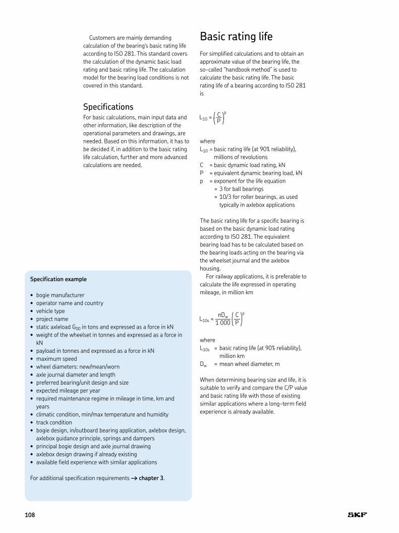
Symmetrical axleboxesIn most cases, the radial load is acting symmetrically either on top of the axlebox or on both sides .
In case of such symmetrical axlebox designs:
Fr = Kr
whereFr = radial bearing load [kN]
Non-symmetrical axleboxesNon-symmetrical axleboxes, like link arm designs, have to be specially calculated as mentioned in the calculation example 2 († page 114) .
Axial bearing loadThe mean axial load is calculated by considering the dynamic axial forces on the axlebox .
Ka = f0 fad G
wherefad = dynamic axial factorFa = Ka
Equivalent bearing load PThe equivalent bearing load to be used for the L10 basic rating life calculation either as described before or based on specific customer load configurations is as follows:
P = Fr + Y Fa for tapered roller bearings and spherical roller bearingsP = Fr for cylindrical roller bearings
whereP = equivalent dynamic bearing load [kN]Y = axial load bearing factor
l
Link arm axlebox calculation model
lh 5
111
Design examples of axleboxes where the radial load is acting symmetrically either on top of the axlebox or on both sides
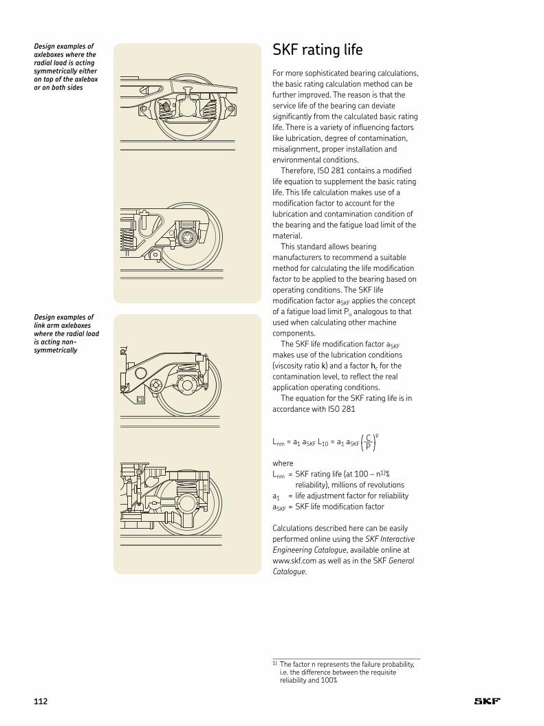
SKF rating lifeFor more sophisticated bearing calculations, the basic rating calculation method can be further improved . The reason is that the service life of the bearing can deviate significantly from the calculated basic rating life . There is a variety of influencing factors like lubrication, degree of contamination, misalignment, proper installation and environmental conditions .
Therefore, ISO 281 contains a modified life equation to supplement the basic rating life . This life calculation makes use of a modification factor to account for the lubrication and contamination condition of the bearing and the fatigue load limit of the material .
This standard allows bearing manufacturers to recommend a suitable method for calculating the life modification factor to be applied to the bearing based on operating conditions . The SKF life modification factor aSKF applies the concept of a fatigue load limit Pu analogous to that used when calculating other machine components .
The SKF life modification factor aSKF makes use of the lubrication conditions (viscosity ratio k) and a factor hc for the contamination level, to reflect the real application operating conditions .
The equation for the SKF rating life is in accordance with ISO 281
Lnm = a1 aSKF L10 = a1 aSKF
whereLnm = SKF rating life (at 100 – n1)% reliability), millions of revolutionsa1 = life adjustment factor for reliabilityaSKF = SKF life modification factor
Calculations described here can be easily performed online using the SKF Interactive Engineering Catalogue, available online at www .skf .com as well as in the SKF General Catalogue .
Design examples of link arm axleboxes where the radial load is acting non-symmetrically
1) The factor n represents the failure probability, i .e . the difference between the requisite reliability and 100%
112

Calculation example 1, symmetrical axlebox without link arm, tapered roller bearing unit
Project data
Customer Calculation example 1Application Electrical multiple unit / symmetrical axlebox / TBU
Application data
Static axleload G00 16,5 tonnes (161,87 kN)Wheelset weight Gr 1,5 tonnes (14,72 kN)Wheel diameter Dw 0,88 mMaximum speed 120 km/hAxlebox type Symmetrical axlebox (without link arm)
Bearing data
Bearing type TBU 130 x 230Basic dynamic load rating C 913 kNOuter ring raceway angle 10 degrees
Bearing boundary dimensions:Bore diameter 130 mmOutside diameter 230 mmWidth 160 mm
Axlebox load calculation
Axlebox load G = (G00 - Gr) / 2 = 73,58 kNEquivalent radial axlebox load Kr = f0 frd ftr G = 88,07 kNEquivalent axial axlebox load Ka = f0 fad G = 6,99 kN
where:f0 = payload factor: 0,95frd = dynamic radial factor: 1,20fad = dynamic axial factor: 0,10ftr = dynamic traction factor: 1,05
Bearing load calculation
Bearing load Fr = Kr + 2 fc Ka = 92,10 kN
where: fc = h Da / l = 0,29Da = shaft diameter 130,00 mml = distance between the 2 load centres = 112,60 mmh = 0,25with:h = 0,25 if the load acts at the top or at the bottom of the housingh = 0,10 if the load acts near to the central plane of the bearing
Fa = Ka = 6,99 kN
where:Fa = mean bearing axial load
Equivalent dynamic bearing load P = Fr + Y Fa = 109,94 kN
Basic rating life calculation
Basic rating life L10 = (C / P)10/3 (for roller bearings) = 1 160 million revolutionsL10s = π × L10 × Dw / 1 000 = 3,2 million km
where:C = basic dynamic load rating = 913,00 kNP = equivalent dynamic bearing load = 109,94 kNDw = Wheel diameter = 0,88 mC/P = 8,3
5
113

Calculation example 2, link arm axlebox, tapered roller bearing unit
Project data
Customer Calculation example 2Application Locomotive / link arm axlebox / TBU
Application data
Static axleload G00 22,5 tonnes (220,73 kN)Wheelset weight Gr 2,88 tonnes (28,25 kN)Wheel diameter Dw 1,06 mMaximum speed 120 km/hAxlebox type Link arm axlebox
Bearing data
Bearing type TBU 160 x 280Basic dynamic load rating C 1 320 kNOuter ring raceway angle 10 degrees
Bearing boundary dimensions:Bore diameter 160 mmOutside diameter 280 mmWidth 180 mm
Axlebox load calculation
Axlebox load G = (G00 - Gr) / 2 = 96,24 kNEquivalent radial axlebox load Kr = f0 frd ftr G = 131,36 kNEquivalent axial axlebox load Ka = f0 fad G = 11,55 kN
where:f0 = payload factor: 1,00frd = dynamic radial factor: 1,30fad = dynamic axial factor: 0,12ftr = dynamic traction factor: 1,05
Bearing load calculation
Bearing load Fr = (Kr2 + Q2)0,5 = 137,08 kN
where: Q = Ka lh / l = additional load due to axlebox arm 39,19 kNl = distance between the 2 load centres = 132,60 mmlh = distance between journal axle and silentblock 450,00 mm
Fa = Ka = 11,55 kN
where:Fa = mean bearing axial load
Equivalent dynamic bearing load P = Fr + Y Fa = 166,56 kN
Basic rating life calculation
Basic rating life L10 = (C / P)10/3 (for roller bearings) = 992 million revolutionsL10s = π × L10 × Dw / 1 000 = 3,3 million km
where:C = basic dynamic load rating = 1 320,00 kNP = equivalent dynamic bearing load = 166,56 kNDw = Wheel diameter = 1,06 mC/P = 7,9
114

Calculation example 3, symmetrical axlebox, cylindrical roller bearing unit
Project data
Customer Calculation example 3Application Freight car / symmetrical axlebox / CRU
Application data
Static axleload G00 25 tonnes (245,25 kN)Wheelset weight Gr 1,25 tonnes (12,26 kN)Wheel diameter Dw 0,88 mMaximum speed 100 km/hAxlebox type Symmetrical axlebox (without link arm)
Bearing data
Bearing type CRU 130 x 240Basic dynamic load rating C 1 010 kNOuter ring raceway angle 0 degrees
Bearing boundary dimensions:Bore diameter 130 mmOutside diameter 240 mmWidth 160 mm
Axlebox load calculation
Axlebox load G = (G00 - Gr) / 2 = 116,49 kNEquivalent radial axlebox load Kr = f0 frd ftr G = 118,82 kNEquivalent axial axlebox load Ka = f0 fad G = 9,90 kN
where:f0 = payload factor: 0,85frd = dynamic radial factor: 1,20fad = dynamic axial factor: 0,10ftr = dynamic traction factor: 1,00
Bearing load calculation
Bearing load Fr = Kr + 2 fc Ka = 122,04 kN
where: Fr = mean bearing radial load 122,04fc = h Da / l = 0,16Da = shaft diameter 130l = distance between the 2 load centres = 80with:h = 0,25 if the load acts at the top or at the bottom of the housingh = 0,10 if the load acts near to the central plane of the bearingFa = Ka = 9,90 kN
where:Fa = mean bearing axial load
Equivalent dynamic bearing load P = Fr 122,04 kN
Basic rating life calculation
Basic rating life L10 = (C / P)10/3 (for roller bearings) = 1 146 million revolutionsL10s = π × L10 × Dw / 1 000 = 3,2 million km
where:C = basic dynamic load rating = 1 010,00 kNP = equivalent dynamic bearing load = 122,04 kNDw =Wheel diameter = 0,88 mC/P = 8,28
5
115

Advanced calculationsSKF has one of the most comprehensive and powerful sets of modelling and simulation packages in the bearing industry . They range from easy-to-use tools, based on SKF General Catalogue formulae, to the most sophisticated calculation and simulation systems running on parallel computers . One of the most used tools in SKF for advanced life calculations is the SKF bearing beacon .
SKF bearing beaconThe SKF bearing beacon is the mainstream bearing application programme used by SKF engineers to optimize the design of customers' bearing arrangements . Its technology enables modelling in a 3D graphic environment of flexible systems incorporating customer components . SKF bearing beacon combines the ability to model generic mechanical systems (using also shafts, gears, housings etc .) with a precise bearing model for an in-depth analysis of the system behaviour in a virtual environment . It also performs rolling bearing raceway fatigue life evaluations using the SKF rating life in particular . SKF bearing beacon is the result of several years of specific research and development within SKF .
For SKF axlebox bearing/unit calculations, the SKF bearing beacon is mainly used for investigating the load distribution on rollers and inner/outer ring raceways for specific applications with load offset, axle journal bending, extreme temperature conditions etc .
Comparison of input data requirements for a handbook calculation with those for the SKF bearing beacon calculation
Input“SKF bearing beacon”
Input “handbook method”
Otherinputs
Microgeometry
Contamination
Bearing clearance
Axleload
Axleboxdesign
Bearingdimensions
116

20 000 [N]15 00010 0005 0000
90°
270° [deg]
180° 0°
90°
270°
180° 0°
14 00010 000
6 0002 000
0
Input data example, geometry of outer ring, roller, flange and raceway
SKF bearing beacon calculated roller contact loads The red and blue colours relate to the two different roller bearing sets. The calculation is typically done for various load conditions. As an example, two of them feature here
XB
A
r2 r4
b
h3ehe
DikDmin
MwPw
R
A
0
5
117

ediyi
Fr
edi yi
Frdi
Influence of the bearing clearance on the load distribution of the roller set
Optimization capabilitiesIn addition to the above-mentioned programmes, SKF has developed dedicated computer programmes that enable SKF engineers to provide customers with bearings that have an optimized surface finish to extend bearing life under severe operating conditions . These programmes can calculate the lubricant film thickness in elasto-hydrodynamically lubricated contacts . In addition, the local film thickness resulting from the deformation of the three dimensional surface topography inside such contacts is calculated in detail .
In order to complete the necessary capabilities needed for their tasks, SKF engineers use commercial packages to perform (e .g . finite element or generic system) dynamic analyses . These tools are integrated into the SKF proprietary systems enabling a faster and more robust connection with customer data and models . Some examples of advanced calculations follow .
Bearing clearanceBearing internal clearance is defined as the total distance through which one bearing ring can be moved relative to the other in the radial direction (radial internal clearance) or in the axial direction (axial internal clearance) .
It is necessary to distinguish between the internal clearance of a bearing before mounting and the internal clearance in a mounted bearing which has reached its operating temperature (operational clearance) . The initial internal clearance (before mounting) is greater than the operational clearance because different degrees of interference in the fits and differences in thermal expansion of the bearing rings and the associated components cause the rings to expand or compress .
Load distribution on the roller set / outer ring raceway
Clearance > 0Clearance = 0
Load distribution
118

Local stress calculationSome applications need to operate outside normal conditions . In these cases, SKF can offer advanced analysis using commercial FEM packages and, more importantly, proprietary software tools developed in-house . This, in combination with more than 100 years of experience, can provide valuable knowledge about the expected performance of an application . One example is an application of an advanced engineering calculation to investigate the local stresses in an inner ring to evaluate the risk of fatigue .
FEM model of an inner ring of a tapered roller bearing unit fitted on an axle journal
Calculation results of the inner ring stresses in an application with an axle journal with a large recess
Influence of the adapter geometryAdapter designs used for tapered roller bearing units in freight or metro applications influence the contact pressure on the roller set, which has a direct impact on bearing performance . The shape and flexibility of the adapter can deform the bearing outer ring . This affects the bearing operating conditions . SKF has developed methods and software tools to analyse such problems and can offer customers in-depth analysis and advice in these situations .
Model of a tapered roller bearing application with a saddle adapter
Contact pressure on the outer ring raceway for an adapter application
Contact pressure
Raceway coordinate
Outer ring raceway pressure
5
119

Cage modelling and calculationIn operation, the rolling elements pass from the loaded into the unloaded zone where the cage has to guide them . SKF developed this simulation method for bearings in railway applications to analyse the elastic behaviour of the cage under all types of vibrations and shocks, such as the influence of wheel flats and rail joints . The cage is modelled as an elastic structure where the cage mass is uniformly distributed over each mass centre of the cage bars (prongs) that are connected by springs with radial, tangential and bending stiffness . The motion of each mass of rolling elements is described by a group of differential equations that are numerically solved in the simulation programme . The results of these equations have been verified experimentally, based on operating conditions covering most practical situations .
The inertia and support forces acting on the cage produce internal stresses . In the model of a cage cross section, the internal forces, F, and the moments, M, acting on the cross sections of the bars, s, and the lateral ring, r, are displayed . The nominal value of the normal stress is calculated as a function of the longitudinal forces and bending moments, while the nominal value of shear stress is derived from the transverse forces and the torsional moments . The stress components can be combined into an equivalent stress according to the form change energy hypothesis [25] .
0
a
s
as
a
belbeA
bekbk
CrCt
Cd
bA
b1 b
e10L
Sk
FLA
SwW
k
l
eA
ek rk
r
Dynamic model for simulation of the cage forces
Calculation results of a FEM design optimization of a cage lateral ring and bar of a tapered roller bearing unit polymer cage
120

Mrzz
z
y
yx
x
Msz
Msx
Fsz
Fsx
Fsy
Mry
Mrx
Msy
Frz
Frx
Fry
sbxy
sbzx
tFyz sy sbzy tMyx;tMyz
tMxy;tMxz
tFxy;tFxz
tFyx
sbyx
sx
Forces, moments and resultant stresses in sections of a cage lateral ring and bar
5
121

® SKF, AMPEP, @PTITUDE, AXLETRONIC, EASYRAIL, INSOCOAT, MRC, MULTILOG are registered trademarks of the SKF Group .
All other trademarks are the property of their respective owner .
© SKF Group 2012The contents of this publication are the copyright of the publisher and may not be reproduced (even extracts) unless prior written permission is granted . Every care has been taken to ensure the accuracy of the information contained in this publication but no liability can be accepted for any loss or damage whether direct, indirect or consequential arising out of the use of the information contained herein .
PUB 42/P2 12789 EN · 2012
Certain image(s) used under license from Shutterstock .com
Bearings and unitsSeals Lubrication
systems
Mechatronics Services
The Power of Knowledge Engineering
Drawing on five areas of competence and application-specific expertise amassed over more than 100 years, SKF brings innovative solutions to OEMs and production facilities in every major industry world-wide. These five competence areas include bearings and units, seals, lubrication systems, mechatronics (combining mechanics and electronics into intelligent systems), and a wide range of services, from 3-D computer modelling to advanced condition monitoring and reliability and asset management systems. A global presence provides SKF customers uniform quality standards and worldwide product availability.
ReferencesLiang, B.: [25] Berechnungsgleichungen für Reibmomente in Planetenwälzlagern. Ruhr-Universität Bochum. Fakultät für Maschinenbau, Institut für Konstruktionstechnik. Schriftenreihe Heft 92.3.
www.railways.skf.com
![INDEX [ ] · PDF filerudder-design calculations ... bearing carrier, photo.....527 ... fractional sailplan, drawing....497 keel casing, photos](https://static.fdocuments.net/doc/165x107/5aa194617f8b9ac67a8bf8f5/index-calculations-bearing-carrier-photo527-fractional-sailplan.jpg)