Beams and Shells modelling: FEM Beams, Shells, Solid...
60
Beams and Shells modelling: FEM Beams, Shells, Solid shells, SPH Shells A Combescure LaMCoS INSA-CNRS 1
Transcript of Beams and Shells modelling: FEM Beams, Shells, Solid...
Beams and Shells modelling: FEM Beams, Shells, Solid shells, SPH
Shells A Combescure
LaMCoS INSA-CNRS
1

Definition
• Most structures are relatively thin: one dimension much smaller than the others…
They are called « SHELLS ». Examples airplane wing, car, boat shell, nearly all buildings…
• If two dimensions are much smaller then the others they are called BEAMS
t A B
F t << L
L Thickness in y direction = b<<L
z
y
x

Motivations • If one wants to predict their mechanical behavior one may of
course use standard Continuum FEM
• BUT : if these structures have to face bending forces e.g.
The computations require too many elements. Typically with standard linear elements 10 across the thickness… => a huge number of elements for a « reliable » prediction… => a huge CPU power…..example : square beam t=b=1mm L=2m, 10 8 nodes cubes across thickness =>200 000 elements square plate t=1mm L*L=2m 40 000 000 elements
t
L
A B
F x
z
y
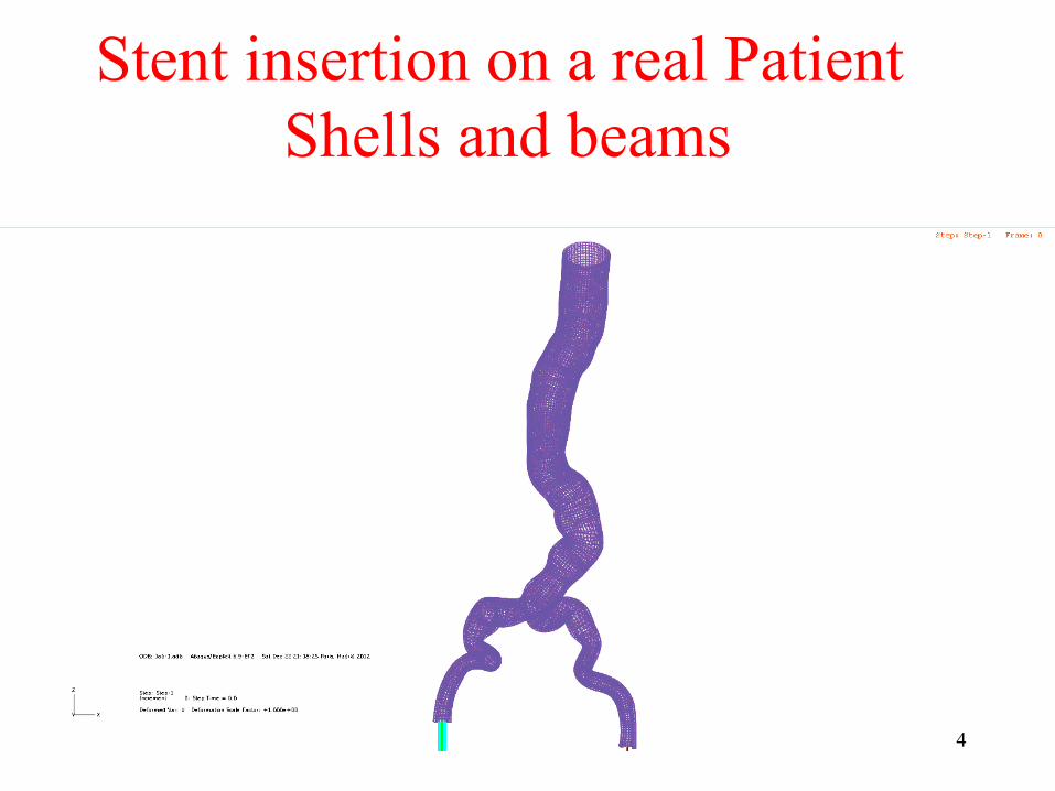
Stent insertion on a real Patient Shells and beams
4

Helicopter engine failure in case of Blade shedding
5

Motivations
• Hence the Beam and Shell theory have been proposed which allows to replace a full 3D approximate solution (with FEM) by a 1D (for BEAMS) or 2D other approximation (for SHELLS)
• By the way beam (especially) and shell model (less frequent) have been used BEFORE 3D continuum mechanics
• These 1D and 2D models have been the first practical applications of FEM. (Planes 2nd World war)
6
Motivations • The main hypothesis and simplifications
of 3D continuum mechanics which lead to beam and shell main ideas shall be presented.
• The most often used 3D shell elements shall be presented.
• The SOLID SHELL concept shall also be presented
7

The main ideas to construct a beam theory: displacements
• Basic introduction: 1D straight beam Initial position P or Q Deformed P’ or Q’ • Geometrical presentation.
• The normal section remains straight after deformation
x
Normal direction n
ux P( ) = uuz (P) = wux Q( ) = u+ z βuz Q( ) = w
P x
z
Q P’
Q’
z
z
u w
βz
Q on n
P on the Mean line (x)
!
z = PQ
8

The main ideas to construct a 2D Straight beam theory: displacements
• The displacement field linear approximated by:
• Axial displacement u : linear function of z • Normal displacement w is constant along z. • All displacement expressed on with quantities measured
on the mean Fiber ó u,w,β functions of x only (not z) • The sections remain plane after deformation!!!
ux x, y( ) = u x( )+ z β x( )uz x, y( ) = uz0 x( ) = w x( )
9

The main ideas to construct a 2D Straight beam theory: kinematics
• 1D straight beam
• 3 Kinematic variables only depend on x ó 1D:
• Axial displacement u , normal displacements w, and rotation of the normal
x
z
u x( ), β x( ),w x( )
β10

The main ideas to construct a 2D straight beam theory: Navier ≠ Timoshenko
P
P’ slope = β = dw
dx= w, x
Deform
ed normal
Q’ on deformed normal Navier
Q’ on deformed Timoshenko
γ
Q on initial normal fiber
11
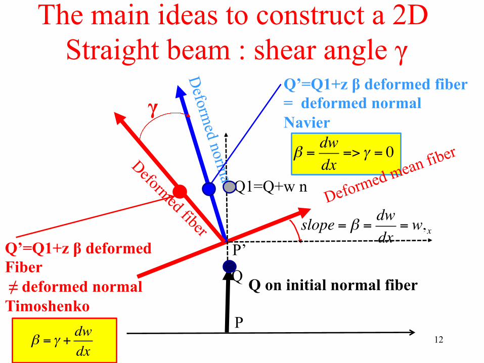
The main ideas to construct a 2D Straight beam : shear angle γ
P
Q P’
slope = β = dwdx
= w, x
Deform
ed normal
Q’=Q1+z β deformed fiber = deformed normal Navier
Q’=Q1+z β deformed Fiber ≠ deformed normal Timoshenko
γ
Q on initial normal fiber
β =dwdx
=> γ = 0
β = γ +dwdx
Q1=Q+w n
12
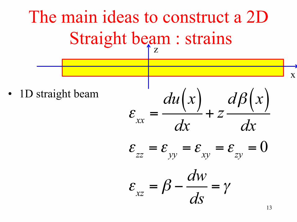
The main ideas to construct a 2D Straight beam : strains
• 1D straight beam
x
z
εxx =du x( )dx
+ zdβ x( )dx
εzz = ε yy = εxy = εzy = 0
εxz = β −dwds
= γ13
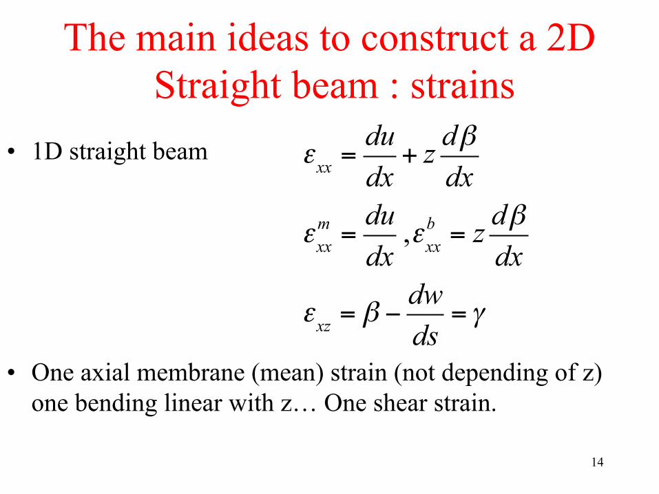
The main ideas to construct a 2D Straight beam : strains
• 1D straight beam
• One axial membrane (mean) strain (not depending of z)
one bending linear with z… One shear strain.
εxx =dudx
+ z dβdx
εxxm =
dudx,εxxb = z dβ
dx
εxz = β −dwds
= γ
14
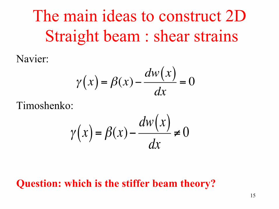
The main ideas to construct 2D Straight beam : shear strains
Navier:
Timoshenko: Question: which is the stiffer beam theory?
γ x( ) = β(x)−dw x( )dx
= 0
γ x( ) = β(x)−dw x( )dx
≠ 0
15

The main ideas to construct a 2D Straight beam : local stresses
• Stresses
• E Young’s modulus membrane Bending
• Shear stress
G Shear modulus Navier
σ xx x, z( ) = Eεxx x, z( ) = E εxxm + z dβ
dx!
"#$
%&
σ xxm = Eεxx
m σ xxb = zEχ xx
σ xz = k G γ
= 0 16

The main ideas to construct a 2D Straight beam : local stresses
• Stresses are linear across the thickness maximum on the skin z= +t/2 or –t/2 is the curvature of the beam Shear stress • No shear stress for Navier = Cst across thickness
for Timoshenko… Why k?
σ xx x, z( ) = Eεxxm + zEχ xx =σ xxm +
2ztσ xx
b
σ xz = k G γ
χ xx =dβdx
17

The main ideas to construct 2D Straight beam : local shear stresses
Shear stress • Why and what value for k? • Exact solution of beam pure bending. Shear stress
are parabolic across the thickness, zero on each skin and maximum at the mid fiber
• Timoshenko proposition: approximate shear stress exact for z=0 =>K= 2/3
• FEM practice : Same strain energy for approximate and exact solution => k=5/6 (usual practice..)
σ xz = k G γ
18

The main ideas to construct a 2D Straight beam : Generalised stresses
N,M • For linear response stress resultants are sufficient
• Axial stress resultant N and Transverse shear T • Bending Moment M
Nxx = b σ xxm + zσ xx
m( )−t/2
+t/2∫ dz = btσ xx
m = Sσ xx
Tzz = b σ xz( )−t/2
+t/2∫ dz = btσ xz = Sσ xz
Myy = b (σ xxm + zσ xx
b
−t2
+t2
∫ )zdz = b t3
12σ xx
b = EIχ xx19

Comparison of Timoshenko and Navier for a beam in bending
• Example of a beam in pure bending
• Navier vertical displacement of point B
• Timoshenko
• Timoshenko softer and Significative difference if t/L close to 1
t A B
F L
wNAVIER = 4FbE
Lt
!
"#
$
%&3
wTIMOSHENKO = wNAVIER 1+1+νk
tL⎛
⎝⎜
⎞
⎠⎟
2⎡
⎣
⎢⎢
⎤
⎦
⎥⎥
20
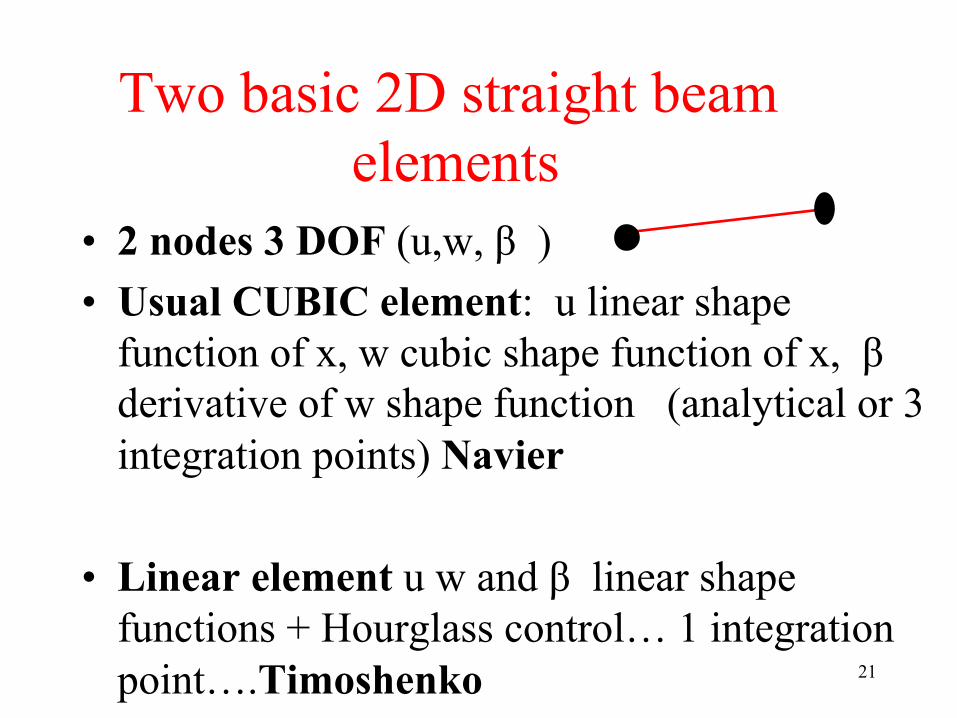
Two basic 2D straight beam elements
• 2 nodes 3 DOF (u,w, β ) • Usual CUBIC element: u linear shape
function of x, w cubic shape function of x, β derivative of w shape function (analytical or 3 integration points) Navier
• Linear element u w and β linear shape functions + Hourglass control… 1 integration point….Timoshenko 21

2D General straight beam (any orientation in X,Z plane)
• Only one change : change of reference frame • Direction x,z are the LOCAL straight beam
directions • Compute the matrices in LOCAL (x,z) frame
and rotate towards general Frame X,Z (Rotation Matrix R constant for straight beam)
x
X
Z z
22
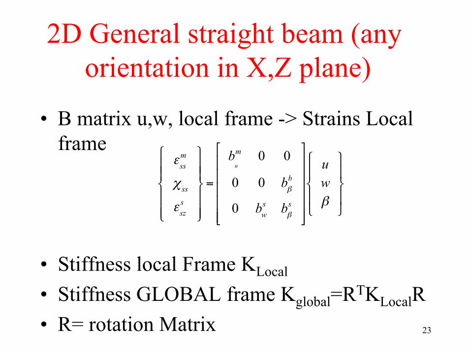
2D General straight beam (any orientation in X,Z plane)
• B matrix u,w, local frame -> Strains Local frame
• Stiffness local Frame KLocal • Stiffness GLOBAL frame Kglobal=RTKLocalR • R= rotation Matrix
εssm
χ ssεszs
⎧
⎨⎪⎪
⎩⎪⎪
⎫
⎬⎪⎪
⎭⎪⎪
=
bu
m 0 0
0 0 bβb
0 bws bβ
s
⎡
⎣
⎢⎢⎢⎢⎢
⎤
⎦
⎥⎥⎥⎥⎥
uwβ
⎧
⎨⎪
⎩⎪
⎫
⎬⎪
⎭⎪
23

3D Straight beams • Simply add a y direction • 3 Normal Stress resultants: one axial Nxx and two shear
Tzz and Tyy • 3 Moments: 2 bending Myy, Mzz and one torsion Mxx
• 3 displacements, 3 rotations . • Resultant stresses in LOCAL frame x,y,z. Stiffness in
local frame (x,y,z) then rotate to GLOBAL frame XYZ (obtained by same equation as before)
24

3D Curved beams • 3 nodes => only one radius of curvature in
the plane • Strains at any point in the element (in the
local FRAME direction ). Compute strains using displacements and rotations in the local FRAME direction.
• Compute B in the LOCAL frame (different at each gauss point) => Rotation matrix is changing with position within the element 25

3D Curved beam Strains (in the local Frame s,n)
• 3D Curved beam
• R Radius of curvature • One axial membrane (mean) strain (not depending of z)
one bending linear with z… One shear strain.
εssm =
duds+wR,εss
b = z dβds
−1Rduds
"
#$
%
&'
εsz = β −dwds
+uRR
n w
s u
26

3D Curved beams • From BLOCAL
• Compute the contribution of This Gauss point to stiffness in LOCAL Frame Then ROTATE this contribution and assemble GLOBAL Stiffness K
27

The locking in Timoshenko straight beams
• As in the solids see (Lesson 8 Tkachuck course) for symptoms and how to Cure them
• Some specific locking: shear locking
• Shear Locking if e.g β and w linear interpolation…. One simple solution under integration BUT Hourglass modes…..w +1 -1 +1 -1 oscillations => Add Hourglass control
εsz = β −dwds
28

The locking in curved beams
• Membrane locking due to curvature terms w/R • Does not exist for straight beams (1/R=0) • Extra shear locking (presence of u/R)
• Specific curing techniques…..
εxxm =
duds+wR,εxx
b = z dβds
−1Rduds
"
#$
%
&'
εxz = β −dwds
+uR
29
Mass matrix • Consistent
• Lumped
• Frequencies for membrane response low (vibration wave length = element length L), bending and shear much higher frequencies (wave length (thickness t)) t<<L
30

Mass matrix: explicit dynamics Frequencies for membrane, bending, shear modes….are very different. Consequencies for explicit dynamics: very small time steps if no special treatment Why do the explicit codes have larger time steps? ….. Mass scaling only on rotation inertial terms β 31

Shells : essentially the same ingredients 2 directions in space….
Good books EG JL Batoz • Strains in local tangent frame x,y. (z normal to x,y
plane) • 6 DOF / node (3 translations, 3 rotations) ó beams • Zero Normal stress • Plane stress strain law • KIRCHOFF/LOVE No transverse shear strains • REISNER/MINDLIN Transverse shear strains and
stresses constant across the thickness
σ zz = 0
σ xz σ yz 32

Flat shells
• Main concept
• Superposition of a membrane element (2D plane stress element) and a Flat Plate
• Membrane element -> usual 2D strains • Bending strains plate theory • Reissner mindlin shear strains plate theory 33

Flat shells (plane x,y)
• Displacements approximation
• For membrane strains in plane u (x,y) x direction, v(x,y) y direction
• For Bending strains, w(x,y) (z direction) +Rotations θx(x,y), θy(x,y),
• Drilling rotation θz(x,y) • Displacement at point Q =
• Shear
34
x
y z
U (x, y, z) = u(x, y)− zθ y (x, y)
V (x, y, z) = v(x, y)+ zθx (x, y)W (x, y, z) = w(x, y)

Flat shells (plane x,y)
• Strain equations • Membrane
• Bending
• Shear 35
εxxb = −z
∂θ y∂x,ε yyb = z ∂θx
∂x,εxyb =
z2∂θx∂y
−∂θ y∂x
⎛
⎝⎜⎜
⎞
⎠⎟⎟
εxxm =
∂u∂x,ε yym =
∂v∂y,εxym =
12∂u∂y
+∂v∂x
⎛
⎝⎜
⎞
⎠⎟
εxzs =
12∂w∂x
−θ y⎛
⎝⎜
⎞
⎠⎟,ε yz
s =12∂w∂y
+θx⎛
⎝⎜
⎞
⎠⎟

Curved shells • Strain equations • Ancien formulation take the 2 curvatures into account in strain • Modern approach (Ahmad): use membrane
+ Plate approximation in the tangent plane at each Gauss point. The normal is changing and approximates the curvature. Much more simple to implement and developp.
36
x x
x
x
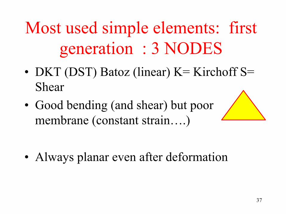
Most used simple elements: first generation : 3 NODES
• DKT (DST) Batoz (linear) K= Kirchoff S= Shear
• Good bending (and shear) but poor membrane (constant strain….)
• Always planar even after deformation
37

Most used simple elements: first generation : 4 Nodes
• Bathe MITC4, Q4γ24 Batoz • Good membrane bending and shear
response …are « naturally » curved with modern shell approach.
38

Most used simple 4 nodes elements
• S4R in Abaqus (reduced integration with ANS) Check the Hourglass energy!!!!
• Be cautious in case of elastoplasticity because Hourglass control is often based on elasticity => Too stiff control in case of fully plastic element (Zheng & All )
• In explicit dynamics Belytschko Tsai element : excellent and fast.. 1 integration point….
39

Hourglass modes some examples • Here are some examples of Hourglass
modes found in the developpement of 3D Isogeometric shells : in plane modes
40

Hourglass modes some examples • Here are some examples of Hourglass
modes found in the developpement of 3D Isogeometric shells : out of plane modes
41
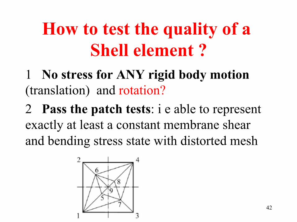
How to test the quality of a Shell element ?
1 No stress for ANY rigid body motion (translation) and rotation? 2 Pass the patch tests: i e able to represent exactly at least a constant membrane shear and bending stress state with distorted mesh
42

How to test the quality of a Shell element ?
3 Pass the shell obstacle course
43
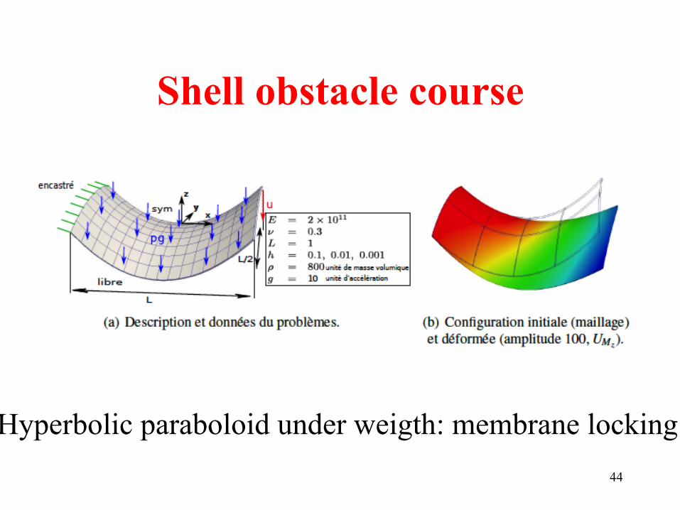
Shell obstacle course
44
Hyperbolic paraboloid under weigth: membrane locking

The shell obstacle course
45 Pinched hemisphere: bending and shear

The shell obstacle course
46 Pinched cylinder: bending and shear locking
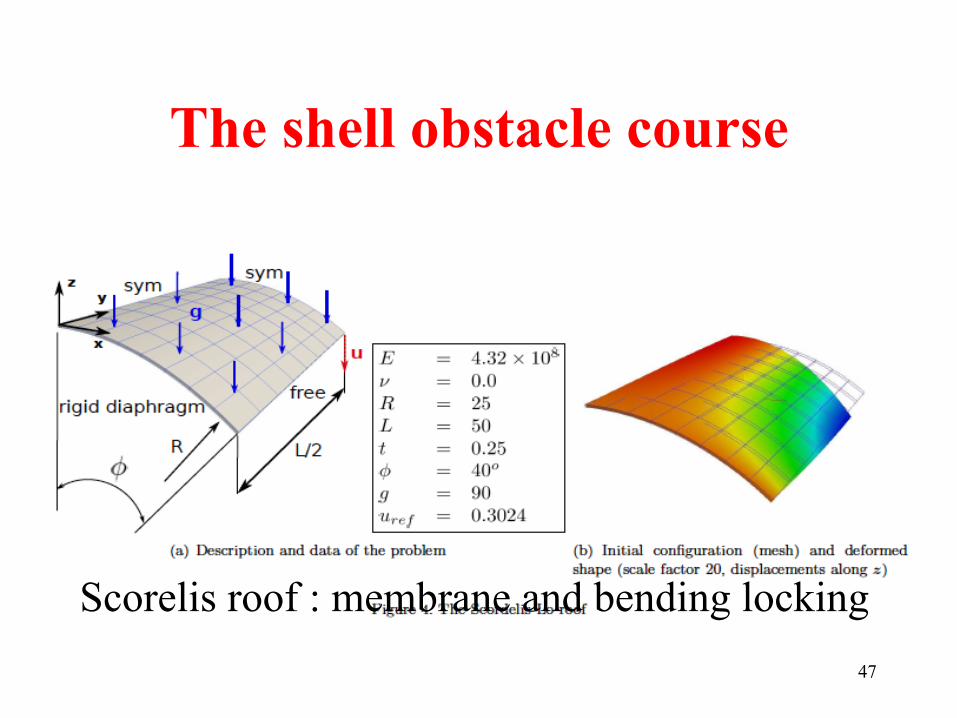
The shell obstacle course
47
Scorelis roof : membrane and bending locking

The shell obstacle course
48
Twisted beam : out of plane distorsion sensitivity

Comments MESHING
• Impossible to have efficient coarse mesh with triangles only in case of membrane loadings.
• Impossible to mesh any shell with only 4 nodes
• Mesh mainly with 4 nodes elements and add 3 nodes elements only where it is compulsary.
49
Comments on PLASTICITY
For plasticity usual practice put points across the thickness compute plane stress state at each point => Stress resultant for equilibrium Rather heavy …. Many integration points ILYUSHIN theory of plasticity very efficient plasticity criterion written only with resultant stresses (Crisfield…) Works quite well (but not often in commercial codes…..)
50

Comments EXPLICIT DYNAMICS
• Lumped mass matrix in explicit dynamics
• Mass scaling on Inertia terms .. Time step is the same for Local bending and streching modes
• OK except if one wants to have bending wave progation or out of plane shear waves.
51

Quadratic Shell elements
• 8 nodes e. g. S8R abaqus , 6 nodes
• Better but rather heavy
• Difficult to use in dynamic explicit context.. • Difficulty for have a GOOD diagonal mass
matrix (contacts difficult to Handle..) 52

SOLID SHELLS
• Try to forget about shells
• E.g. replace 4 nodes shell by 8 node Brick 4 nodes on one skin…. 4 nodes on the second skin
• One (local) direction named thickness • One dimension << the others L>>t ….L/t < 50
Thickness direction
L
t
53

SOLID SHELLS • Use standard 3D stress strain law • => usual locking and curing technique + 1
locking due to large aspect ratio…. (2 integration points +Hourglass control + One extra volumetric locking curing technique)
• See in the litterature (e. g. Reese…(ANS Based methods) SHB8 Abed Meraim)
54

SOLID SHELLS • Plasticity: poor bending behavior with basic
integration (2 points across thickness)
• Use 5 points in « thickness » direction and One point on mid plane… (as in usual 4 Nodes Shells) very good element provided L/t<50
55

SOLID SHELLS
• One basic interpretation PEREGO • Membrane displacement
• Rotations
• On a normal line 6 DOF = 2*3… similar to a 4 Node Shell…
umembrane = 12utop +ubottom( )
Rotation = 1tutop −ubottom( )
Thickness direction
L
t
56

SOLID SHELLS • Explicit dynamics • If used as it is .. Time step too small (t
dimension is small)
• Of change of variable umembrane , rotations + Mass scaling on rotation terms only => large time steps linked to membrane response only (Perego..)
57

SOLID SHELLS • Need a 6 Node Solid shell to mesh any shape…
• This element exist SHB6
58

Last comments on shell models
• Isogeometric representation also works for Shells LS DYNA IMPETUS and ABAQUS
• SPH Shell formulations developped for fracturing shells (Caleyron Maurel)
• ISOGEOMETRIC Solid shells (Elguedj, Bouclier).
59

Examples of SPH Shell and IsoGeometric shells
• SPH Plate perforation Meshing only one layer of Mindlin SPH nodes (Caleyron) • NL Isogeometric Solid Shell (Robin)
60