Beam-transport system of KEKB
16
Nuclear Instruments and Methods in Physics Research A 499 (2003) 8–23 Beam-transport system of KEKB M. Kikuchi*, T. Honda, N. Iida, K. Kanazawa, T. Kubo, T. Mimashi, H. Nakayama, Y. Sakamoto, K. Satoh, Y. Takeuchi, M. Yoshida, M. Yoshioka KEK, National High Energy Accelerator Research Organization, 1-1 Oho, Tsukuba-shi, Ibaraki 305-0801, Japan Abstract The transport lines of the KEKB for positrons and electrons convey the beams separately from the injector linac to the KEKB rings. The length is about 500 m for each line. In order to make the maximum use of the existing tunnels and also to avoid interference with the AR, the beam lines took a serpentine course, resulting in a rather large curvature in the arcs. The consequences were a large number of bends in the arcs with high fields and also a large dispersion function and, thus, a large R 56 component. The latter issue is crucial for the KEKB rings, since it results in a longer bunch length at injection. We adopted a special optics that reduces the R 56 coefficient sufficiently. We have developed novel water- cooled ceramic chambers for kickers, eddy-current-type septum magnets for injection, and a beam-abort system for the rings. The present paper describes the design and current status of the beam lines, the injection system, and the beam- abort system. r 2002 Elsevier Science B.V. All rights reserved. Keywords: Beam; Transport; KEKB; Abort; Kicker; Septum; Ceramic; BPM; Wire 1. Introduction KEKB is an asymmetric double-ring collider of 3.5-GeV positrons (LER) and 8-GeV electrons (HER), filled with a current of 2:6 A for LER and 1:1 A for HER in the design. The beam-transport (BT) lines transfer the positron and electron beams separately from the injector linac to the rings, each having a length of about 500 m: The maximum repetition of the linac is 50 Hz: We describe the BT and the injection system in Sections 2 and 3. The KEKB rings have a beam-abort system to protect the physics detector and accelerator components. It ejects beams to the dump in a single turn. We describe the beam-abort system in Section 4. 2. BT Lines The design specifications of the beam para- meters are given in Table 1. The energy spread of the positron beam at the end of the linac is 2:5 10 3 and is compressed to one-half by the energy compression system (ECS) at the most upstream part of the BT line. 2.1. Layout of the beam lines The layout of the beam lines, shown in Fig. 1, was decided under the guideline that maximum use should be made of the existing Accumulator Ring (AR-) and MR-injection tunnel and as large a separation as possible must be made from the AR, which had been planned to serve as a photon *Corresponding author. E-mail address: [email protected] (M. Kikuchi). 0168-9002/03/$ - see front matter r 2002 Elsevier Science B.V. All rights reserved. doi:10.1016/S0168-9002(02)01785-0
Transcript of Beam-transport system of KEKB

Nuclear Instruments and Methods in Physics Research A 499 (2003) 8–23
Beam-transport system of KEKB
M. Kikuchi*, T. Honda, N. Iida, K. Kanazawa, T. Kubo, T. Mimashi,H. Nakayama, Y. Sakamoto, K. Satoh, Y. Takeuchi, M. Yoshida, M. Yoshioka
KEK, National High Energy Accelerator Research Organization, 1-1 Oho, Tsukuba-shi, Ibaraki 305-0801, Japan
Abstract
The transport lines of the KEKB for positrons and electrons convey the beams separately from the injector linac to
the KEKB rings. The length is about 500 m for each line. In order to make the maximum use of the existing tunnels and
also to avoid interference with the AR, the beam lines took a serpentine course, resulting in a rather large curvature in
the arcs. The consequences were a large number of bends in the arcs with high fields and also a large dispersion function
and, thus, a large R56 component. The latter issue is crucial for the KEKB rings, since it results in a longer bunch length
at injection. We adopted a special optics that reduces the R56 coefficient sufficiently. We have developed novel water-
cooled ceramic chambers for kickers, eddy-current-type septum magnets for injection, and a beam-abort system for the
rings. The present paper describes the design and current status of the beam lines, the injection system, and the beam-
abort system.
r 2002 Elsevier Science B.V. All rights reserved.
Keywords: Beam; Transport; KEKB; Abort; Kicker; Septum; Ceramic; BPM; Wire
1. Introduction
KEKB is an asymmetric double-ring collider of3.5-GeV positrons (LER) and 8-GeV electrons(HER), filled with a current of 2:6 A for LER and1:1 A for HER in the design. The beam-transport(BT) lines transfer the positron and electron beamsseparately from the injector linac to the rings, eachhaving a length of about 500 m: The maximumrepetition of the linac is 50 Hz: We describe the BTand the injection system in Sections 2 and 3. TheKEKB rings have a beam-abort system to protectthe physics detector and accelerator components.It ejects beams to the dump in a single turn. Wedescribe the beam-abort system in Section 4.
2. BT Lines
The design specifications of the beam para-meters are given in Table 1. The energy spreadof the positron beam at the end of the linac is2:5 103 and is compressed to one-half by theenergy compression system (ECS) at the mostupstream part of the BT line.
2.1. Layout of the beam lines
The layout of the beam lines, shown in Fig. 1,was decided under the guideline that maximum useshould be made of the existing Accumulator Ring(AR-) and MR-injection tunnel and as large aseparation as possible must be made from the AR,which had been planned to serve as a photon
*Corresponding author.
E-mail address: [email protected] (M. Kikuchi).
0168-9002/03/$ - see front matter r 2002 Elsevier Science B.V. All rights reserved.
doi:10.1016/S0168-9002(02)01785-0
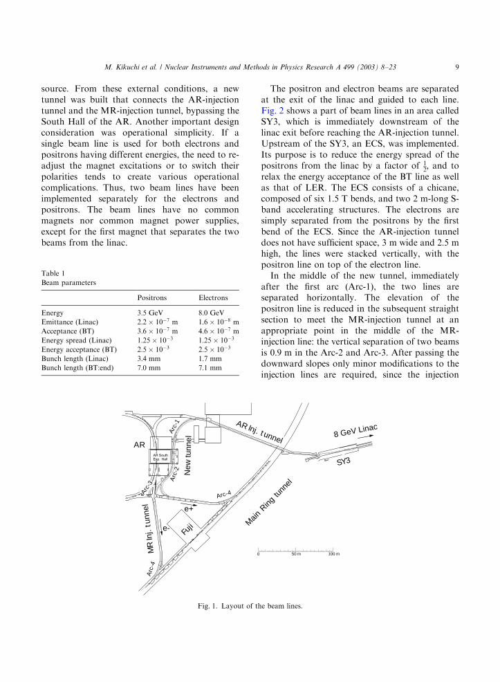
source. From these external conditions, a newtunnel was built that connects the AR-injectiontunnel and the MR-injection tunnel, bypassing theSouth Hall of the AR. Another important designconsideration was operational simplicity. If asingle beam line is used for both electrons andpositrons having different energies, the need to re-adjust the magnet excitations or to switch theirpolarities tends to create various operationalcomplications. Thus, two beam lines have beenimplemented separately for the electrons andpositrons. The beam lines have no commonmagnets nor common magnet power supplies,except for the first magnet that separates the twobeams from the linac.
The positron and electron beams are separatedat the exit of the linac and guided to each line.Fig. 2 shows a part of beam lines in an area calledSY3, which is immediately downstream of thelinac exit before reaching the AR-injection tunnel.Upstream of the SY3, an ECS, was implemented.Its purpose is to reduce the energy spread of thepositrons from the linac by a factor of 1
2; and to
relax the energy acceptance of the BT line as wellas that of LER. The ECS consists of a chicane,composed of six 1:5 T bends, and two 2 m-long S-band accelerating structures. The electrons aresimply separated from the positrons by the firstbend of the ECS. Since the AR-injection tunneldoes not have sufficient space, 3 m wide and 2:5 mhigh, the lines were stacked vertically, with thepositron line on top of the electron line.
In the middle of the new tunnel, immediatelyafter the first arc (Arc-1), the two lines areseparated horizontally. The elevation of thepositron line is reduced in the subsequent straightsection to meet the MR-injection tunnel at anappropriate point in the middle of the MR-injection line: the vertical separation of two beamsis 0:9 m in the Arc-2 and Arc-3. After passing thedownward slopes only minor modifications to theinjection lines are required, since the injection
0 50 m 100 m
AR8 GeV Linac
SY3
e+
e-Fu
ji
AR Inj. t unnel
Main
Ring
tunn
el
Arc
-1A
rc-2
Arc-
3
Arc-4
Arc
-4M
RIn
j.tu
nnel
New
tunn
el
Fig. 1. Layout of the beam lines.
Table 1
Beam parameters
Positrons Electrons
Energy 3:5 GeV 8:0 GeV
Emittance (Linac) 2:2 107 m 1:6 108 m
Acceptance (BT) 3:6 107 m 4:6 107 m
Energy spread (Linac) 1:25 103 1:25 103
Energy acceptance (BT) 2:5 103 2:5 103
Bunch length (Linac) 3:4 mm 1:7 mm
Bunch length (BT:end) 7:0 mm 7:1 mm
M. Kikuchi et al. / Nuclear Instruments and Methods in Physics Research A 499 (2003) 8–23 9

points to the KEKB rings are at nearly the samepositions as those of the TRISTAN MR. Fig. 3shows a typical view at the Arc-1 of the new BTtunnel.
2.2. Optics
Tight constraints on the geometric conditionsled to a large curvature of the beam lines in thenew tunnel. A simple repeat of identical FODOcell would produce a large dispersion function inthe arcs, which would result, combined with thesmall bend radius, a large R56 component. Here,
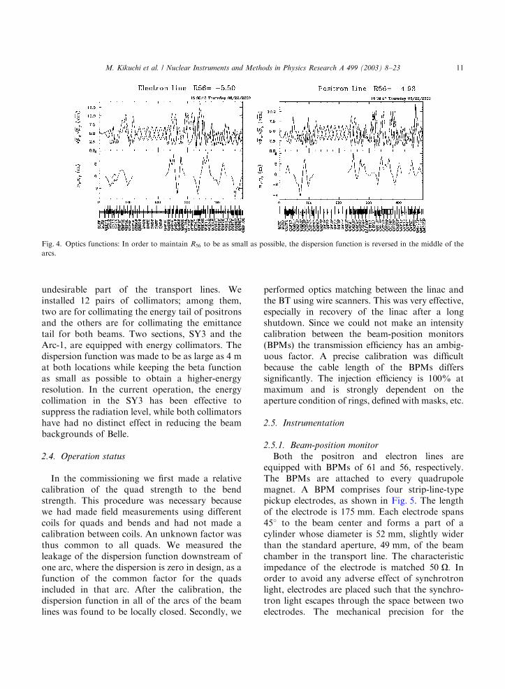
R56 refers to the (5,6) component of the transfermatrix, i.e., the path-length dependence on themomentum. A larger R56 generates a longer bunchlength at the end of BT due to drift in thelongitudinal phase space. A beam with a largebunch length, correlated with momentum, inducesa large quadrupole synchrotron oscillation. Weadopted special optics that reduces R56: the opticsaround the three arcs in the new tunnel wasarranged such that the dispersion function wasreversed in the middle of the arc or upstream ofone arc generated negative dispersion downstreamof the arc so that in total R56 was decreased. Thisapproach demands, however, that almost all quadsare powered independently. In the present optics,the bunch length is still dominated by the long-itudinal drift effects, as shown in Table 1. In thisoptics, the largest energy amplitude of the inducedbunch oscillation immediately after injection ismuch smaller than the longitudinal acceptance ofthe rings in the worst case (0.5%). Fig. 4 shows theoptics function of the beam lines. The dispersionfunction is kept relatively small and closed withineach region. The parameter R56 is 4:9 m forpositrons and 5:5 m for electrons at the end ofthe beam lines.
2.3. Beam halo collimation
Beam halo collimation is vitally important toprotect the fragile detectors of the Belle from lostparticles. Although the KEKB rings have theirown masks, it is preferable to cut the tail part ofthe beams before injection. The collimation systemis also necessary to reduce the beam loss in the
10 20 30 40 50 60 m0
AR injection tunnel
To Photon Factory
e+
e-LINAC
Acc. structures
Linac beam dump
Fig. 2. Layout of the beam switch yard (SY3).
Fig. 3. Typical view from upstream at Arc-1.
M. Kikuchi et al. / Nuclear Instruments and Methods in Physics Research A 499 (2003) 8–2310
undesirable part of the transport lines. Weinstalled 12 pairs of collimators; among them,two are for collimating the energy tail of positronsand the others are for collimating the emittancetail for both beams. Two sections, SY3 and theArc-1, are equipped with energy collimators. Thedispersion function was made to be as large as 4 mat both locations while keeping the beta functionas small as possible to obtain a higher-energyresolution. In the current operation, the energycollimation in the SY3 has been effective tosuppress the radiation level, while both collimatorshave had no distinct effect in reducing the beambackgrounds of Belle.
2.4. Operation status
In the commissioning we first made a relativecalibration of the quad strength to the bendstrength. This procedure was necessary becausewe had made field measurements using differentcoils for quads and bends and had not made acalibration between coils. An unknown factor wasthus common to all quads. We measured theleakage of the dispersion function downstream ofone arc, where the dispersion is zero in design, as afunction of the common factor for the quadsincluded in that arc. After the calibration, thedispersion function in all of the arcs of the beamlines was found to be locally closed. Secondly, we
performed optics matching between the linac andthe BT using wire scanners. This was very effective,especially in recovery of the linac after a longshutdown. Since we could not make an intensitycalibration between the beam-position monitors(BPMs) the transmission efficiency has an ambig-uous factor. A precise calibration was difficultbecause the cable length of the BPMs differssignificantly. The injection efficiency is 100% atmaximum and is strongly dependent on theaperture condition of rings, defined with masks, etc.
2.5. Instrumentation
2.5.1. Beam-position monitor
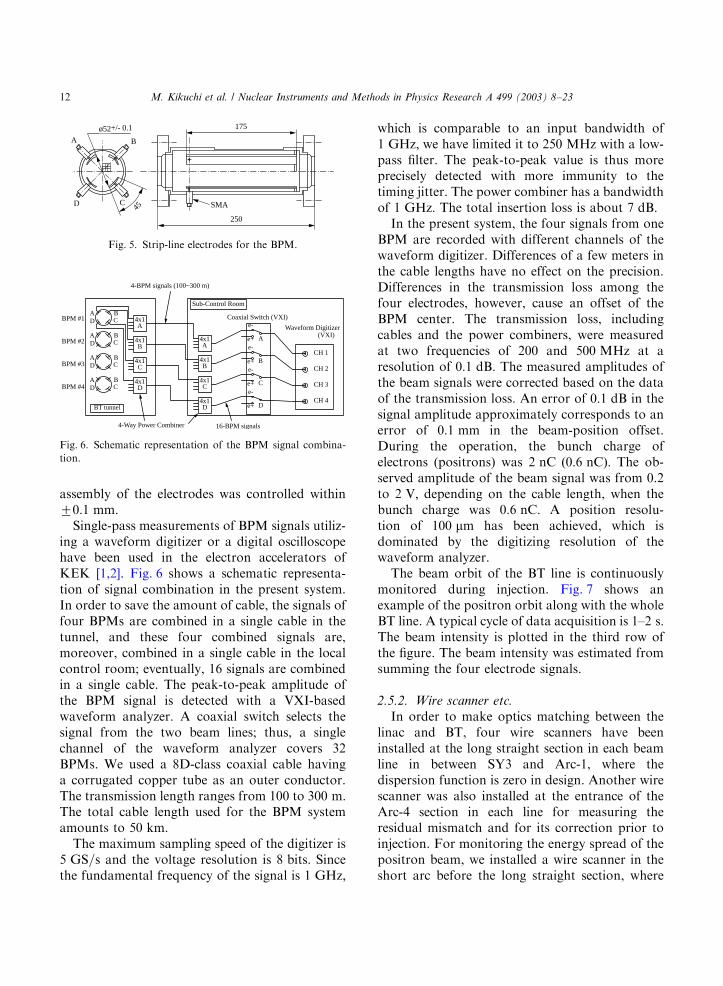
Both the positron and electron lines areequipped with BPMs of 61 and 56, respectively.The BPMs are attached to every quadrupolemagnet. A BPM comprises four strip-line-typepickup electrodes, as shown in Fig. 5. The lengthof the electrode is 175 mm: Each electrode spans451 to the beam center and forms a part of acylinder whose diameter is 52 mm; slightly widerthan the standard aperture, 49 mm; of the beamchamber in the transport line. The characteristicimpedance of the electrode is matched 50 O: Inorder to avoid any adverse effect of synchrotronlight, electrodes are placed such that the synchro-tron light escapes through the space between twoelectrodes. The mechanical precision for the
Fig. 4. Optics functions: In order to maintain R56 to be as small as possible, the dispersion function is reversed in the middle of the
arcs.
M. Kikuchi et al. / Nuclear Instruments and Methods in Physics Research A 499 (2003) 8–23 11
assembly of the electrodes was controlled within70:1 mm:
Single-pass measurements of BPM signals utiliz-ing a waveform digitizer or a digital oscilloscopehave been used in the electron accelerators ofKEK [1,2]. Fig. 6 shows a schematic representa-tion of signal combination in the present system.In order to save the amount of cable, the signals offour BPMs are combined in a single cable in thetunnel, and these four combined signals are,moreover, combined in a single cable in the localcontrol room; eventually, 16 signals are combinedin a single cable. The peak-to-peak amplitude ofthe BPM signal is detected with a VXI-basedwaveform analyzer. A coaxial switch selects thesignal from the two beam lines; thus, a singlechannel of the waveform analyzer covers 32BPMs. We used a 8D-class coaxial cable havinga corrugated copper tube as an outer conductor.The transmission length ranges from 100 to 300 m:The total cable length used for the BPM systemamounts to 50 km:
The maximum sampling speed of the digitizer is5 GS=s and the voltage resolution is 8 bits: Sincethe fundamental frequency of the signal is 1 GHz;
which is comparable to an input bandwidth of1 GHz; we have limited it to 250 MHz with a low-pass filter. The peak-to-peak value is thus moreprecisely detected with more immunity to thetiming jitter. The power combiner has a bandwidthof 1 GHz: The total insertion loss is about 7 dB:
In the present system, the four signals from oneBPM are recorded with different channels of thewaveform digitizer. Differences of a few meters inthe cable lengths have no effect on the precision.Differences in the transmission loss among thefour electrodes, however, cause an offset of theBPM center. The transmission loss, includingcables and the power combiners, were measuredat two frequencies of 200 and 500 MHz at aresolution of 0:1 dB: The measured amplitudes ofthe beam signals were corrected based on the dataof the transmission loss. An error of 0:1 dB in thesignal amplitude approximately corresponds to anerror of 0:1 mm in the beam-position offset.During the operation, the bunch charge ofelectrons (positrons) was 2 nC ð0:6 nCÞ: The ob-served amplitude of the beam signal was from 0.2to 2 V; depending on the cable length, when thebunch charge was 0:6 nC: A position resolu-tion of 100 mm has been achieved, which isdominated by the digitizing resolution of thewaveform analyzer.
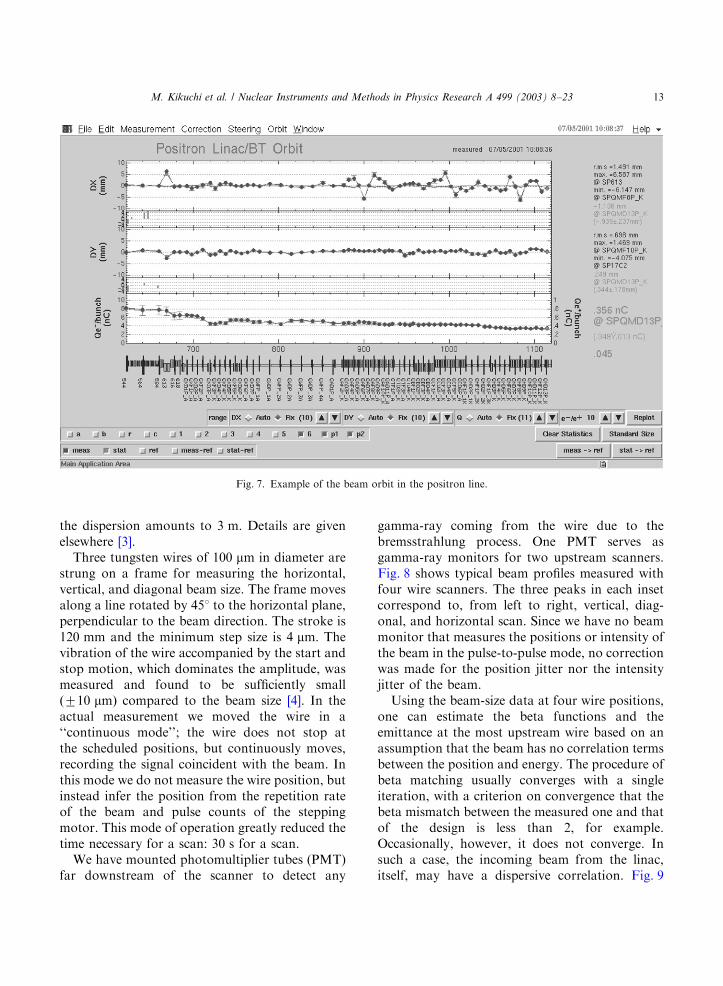
The beam orbit of the BT line is continuouslymonitored during injection. Fig. 7 shows anexample of the positron orbit along with the wholeBT line. A typical cycle of data acquisition is 1–2 s:The beam intensity is plotted in the third row ofthe figure. The beam intensity was estimated fromsumming the four electrode signals.
2.5.2. Wire scanner etc.
In order to make optics matching between thelinac and BT, four wire scanners have beeninstalled at the long straight section in each beamline in between SY3 and Arc-1, where thedispersion function is zero in design. Another wirescanner was also installed at the entrance of theArc-4 section in each line for measuring theresidual mismatch and for its correction prior toinjection. For monitoring the energy spread of thepositron beam, we installed a wire scanner in theshort arc before the long straight section, where
250
175
45
ø52+/- 0.1
SMA
A B
CD
Fig. 5. Strip-line electrodes for the BPM.
A BCDBPM #1
BPM #2
BPM #3
BPM #4
BT tunnel
4x1A
4x1
4x1
4x1
B
C
D
4x1A
4x1
4x1
4x1
B
C
D
Sub-Control Room
4-BPM signals (100~300 m)
Coaxial Switch (VXI)
Waveform Digitizer(VXI)
16-BPM signals
A
e-
e+
B
e-
e+
C
e-
e+
D
e-
e+
CH 1
CH 2
CH 3
CH 4
4-Way Power Combiner
A BCD
A BCD
A BCD
Fig. 6. Schematic representation of the BPM signal combina-
tion.
M. Kikuchi et al. / Nuclear Instruments and Methods in Physics Research A 499 (2003) 8–2312
the dispersion amounts to 3 m: Details are givenelsewhere [3].
Three tungsten wires of 100 mm in diameter arestrung on a frame for measuring the horizontal,vertical, and diagonal beam size. The frame movesalong a line rotated by 451 to the horizontal plane,perpendicular to the beam direction. The stroke is120 mm and the minimum step size is 4 mm: Thevibration of the wire accompanied by the start andstop motion, which dominates the amplitude, wasmeasured and found to be sufficiently smallð710 mmÞ compared to the beam size [4]. In theactual measurement we moved the wire in a‘‘continuous mode’’; the wire does not stop atthe scheduled positions, but continuously moves,recording the signal coincident with the beam. Inthis mode we do not measure the wire position, butinstead infer the position from the repetition rateof the beam and pulse counts of the steppingmotor. This mode of operation greatly reduced thetime necessary for a scan: 30 s for a scan.
We have mounted photomultiplier tubes (PMT)far downstream of the scanner to detect any
gamma-ray coming from the wire due to thebremsstrahlung process. One PMT serves asgamma-ray monitors for two upstream scanners.Fig. 8 shows typical beam profiles measured withfour wire scanners. The three peaks in each insetcorrespond to, from left to right, vertical, diag-onal, and horizontal scan. Since we have no beammonitor that measures the positions or intensity ofthe beam in the pulse-to-pulse mode, no correctionwas made for the position jitter nor the intensityjitter of the beam.
Using the beam-size data at four wire positions,one can estimate the beta functions and theemittance at the most upstream wire based on anassumption that the beam has no correlation termsbetween the position and energy. The procedure ofbeta matching usually converges with a singleiteration, with a criterion on convergence that thebeta mismatch between the measured one and thatof the design is less than 2, for example.Occasionally, however, it does not converge. Insuch a case, the incoming beam from the linac,itself, may have a dispersive correlation. Fig. 9
Fig. 7. Example of the beam orbit in the positron line.
M. Kikuchi et al. / Nuclear Instruments and Methods in Physics Research A 499 (2003) 8–23 13

shows the variation in the optics parametersof the positron line for a period of 20 monthsoperation. The horizontal parameters are dis-played in the left figures while the vertical onesin the right. The bottom row shows the betamismatch. In usual operation the optical para-meters are measured once a day and opticsmatching is made if the beta mismatch is greaterthan the criterion.
Besides wire scanners, 40 profile monitors and23 beam-loss monitors utilizing air-filled coaxialcables have been installed for the lines. The profilemonitors have played a great role in checking thevalidity of the optics matching.
3. Injection system
Since the beam scattering in the window, evenfor Be, produces an enormous emittance increase,we adopted a scheme that does not utilize theinjection window: the vacuum is common for thetransport line and the ring. The dimensions ofthe beam chamber in the injection area of the ringare 65 mm in width, 48 mm in height for HERwhile 76 mm wide and 48 mm high for LER,which are maintained throughout the wholeinjection area in order to maintain smoothness.Four septum magnets for HER and two for LERare used for injection. They are all housed in
Fig. 8. Typical beam profiles in the positron line measured with four wire scanners.
M. Kikuchi et al. / Nuclear Instruments and Methods in Physics Research A 499 (2003) 8–2314

vacuum chambers. Two septum chambers forHER and one septum chamber for LER, whichare nearest to the ring, accommodate the beamchambers of the ring inside of them. The beamchamber of the ring is smoothly connected in theseptum chambers, while keeping its inner dimen-sion. The incoming beam is bent through theseptum magnets and, after the quad, injectedthrough a thin slit which is cut in the beamchamber of the ring. The gap height of the slit is12 mm: A schematic injection orbit is shown inFig. 10 for the HER case.
Since the total bend angle of septa is relativelylarge, 150 mrad for HER and 100 mrad for LER,an angle jitter of 0.1% gives rise to a sizable
increase of the effective beam size. This means thatthe tolerance of each septum magnet must be lessthan 0.02%, which should be relatively tight for apulsed magnet.
3.1. Injection septum
We adopted the ‘‘eddy current’’ type instead ofthe ‘‘current sheet’’ type, because it simplifies theelectrical insulation of the coil, and also helps tomake the septum thinner. In the ‘‘eddy current’’type, on the other hand, the leak field outside ofthe septum is relatively large. In addition, it has aslow component that lasts even after the drivecurrent has ceased. The leak field has a position
Fig. 9. Variation of the optics parameters in the positron line. The parameters in the horizontal plane are drawn in the left column
while those in vertical planes are in the right. From top to bottom, the parameters of a; b; emittance, and beta mismatch are shown.
M. Kikuchi et al. / Nuclear Instruments and Methods in Physics Research A 499 (2003) 8–23 15

dependence; it is smaller at longer distance fromthe septum. Since the position dependence of theslow component is much smaller than that of thefast component, the slow component exists even atthe position of the circulating beam. We adoptedan approach in which the slow component ispartially canceled out by using a full-sine pulse, thepositive swing being canceled with the succeedingnegative swing. The leak field due to the eddycurrent is proportional to the pulse width. For ashorter pulse width, however, a higher voltage isneeded, and it is more difficult to select a goodpower switch. As a compromise we adopted apulse width of 280 ms:
3.1.1. Magnet structure
The main parameters of the septum magnets aregiven in Table 2. The septum thickness in the tableincludes that of the shield plates. The magnet coresare made of 0:1 mm thick laminations stampedfrom silicon steel. The end plates are made of15 mm thick stainless steel. The cores are sur-rounded by copper plates in order to reduce theleakage field. The coil is wound at the back-yokeby one turn and extracted outside of the chamberwithout any connection in the chamber. It makesuse of a copper hollow conductor, which has a
coating of 0:3 mm thick ceramics to protectagainst voltage breakdown and radiation damage.In order to reduce any leakage field due to an eddycurrent in the copper septum, we attached two thinsilicon steel plates of 0:5 mm thick outside thecopper septum.
3.1.2. Power supplies and field measurements
The main capacitors are charged up precisely,with the voltage being controlled in precision by adeQing circuit at a fixed voltage level after thetrigger. The capacitor is discharged by turning onsix switch modules in parallel, each of whichutilizes three thyristers in series; in a negativeswing of the full-sine wave it is re-charged througha diode which is connected to the switch modulesin parallel. The pulse height of the negative swingis 85% of the positive one, due to resistive loss inthe coil and in the circuit. This reduction bringsanother imperfection in the cancellation of the leakfield. Fig. 11 shows the current and voltage form.We have measured the magnetic field in variousconditions. The peak leak field at a distance of30 mm from the septum was 9 G without a beamchamber. In this case, the slow component of theleak field was 3% of the peak leak field. In order tosimulate the effect of the beam chamber we
Fig. 10. Injection orbit of the electron beam. The vertical axis is the horizontal position from the beam center of HER, while the
horizontal axis is the longitudinal position along the HER beam. The inner radius of the ring chamber is 32:5 mm: The beam is injected
through a thin slit of the ring chamber, which is shown by a horizontal broken line. Also shown are the envelope of an injected beam of
2:5s; the kicker orbit, and the envelope of a captured beam.
M. Kikuchi et al. / Nuclear Instruments and Methods in Physics Research A 499 (2003) 8–2316

measured the leak field at the same place within analuminum pipe of 2 mm thick and 20 mm dia-meter. The result was 2:5 G: Since the real beamchamber has a much larger thickness, a muchsmaller leak field is expected in the real configura-tion. We have achieved a voltage jitter of less than0.02%, at least in short period of the observationtime.
3.1.3. Operation status
The septum magnets have been successfullyoperated since December 1998. The vacuum levelin the septum chambers is, however, poor, thoughit has been improved slowly. This may become anissue in the future when the beam current will beincreased. The high pressure in septum chambers ismainly due to out gas from the silicon steel
surface, which is coated with CrO3 that includesan organic material as glue. When septum magnetsare powered the temperature of the core isincreased due to iron loss. Fig. 12 shows thetemperature at various places of the septummagnets as well as the vacuum level in the septumchamber as a function of time during beam fillingin HER, where the current was increased from 540to 770 mA in 3:3 min: Fortunately, thanks to badconductance between the septum chamber and thering chamber, the poor vacuum has a relativelysmall effect on the vacuum in the ring. The abruptincrease in the vacuum pressure at the last minuteof beam filling, seen in Fig. 12, is also observed inthe vacuum pressure in the ring. This phenomenondepends on the bunch current of the beam in thering, and has a threshold. We suspect a HOMresonance near the septum. The vacuum pressureof the ring around the septa is roughly 5–10 timeshigher than those of the normal arc, while thepressure in the septum chamber is as high as threeorders of magnitude. The outgassing rate of siliconsteel that we used is comparable with that ofrubber [5]. It might be necessary in higher currentoperation to replace it with new steel that does notinclude any organic material in the coating.
3.2. Injection kicker
The kicker bump orbit is generated by twogroups of kickers whose horizontal phase differ-ence is 1801: Each group consists of three kickers,i.e., six kickers are used in total for each ring.Single-turn injection needs 1.4 and 2:8 mrad for a
Table 2
Design parameters of the septum magnets
e eþ
Deflection angle (mrad) 37.5 50.0
Number of magnets 4 2
Peak magnetic field (T) 1.04 0.79
Septum thickness (mm) 2.5 2.5
Magnet core length (m) 1.0 0.8
Magnet free aperture (mm) 11H 44W 11H 44W
Laminate steel thickness (mm) 0.1 0.1
Magnet inductance ðmHÞ 7.1 5.7
Peak current (kA) 9.1 6.9
Peak voltage (kV) 1.9 1.4
Voltage stability (%) 0.02 0.02
Pulse width ðmsÞ 280 260
Fig. 11. Left: voltage wave form, vertical scale 500 V=div; horizontal scale 1 ms=div; Right: current wave form, vertical scale 4 kA=div;horizontal scale 50 ms=div:
M. Kikuchi et al. / Nuclear Instruments and Methods in Physics Research A 499 (2003) 8–23 17

group of kickers for HER and LER, respectively.In usual multiple-turn injection we need 0.9 and1:8 mrad at maximum for HER and LER. Sincethe repetition rate is 50 Hz; which is comparable toa transverse damping time of 45 ms of the rings, asmaller pulse width compared to the revolutiontime of 10 ms is necessary to make 50 Hz injectionpossible. We adopted a pulse width of 2 ms:
3.2.1. Kicker magnets and power supplies
The kicker magnets are of the conventionalwindow-frame type using a ferrite core. The ferritecore is 225 mm long and 90 mm high in the freegap. The kicker is mounted on a ceramic vacuumchamber. The maximum voltage and current of thepower supply are 35 kV and 2000 A and themagnetic field is 550 G: The voltage is low enoughfor stable operation of the thyratrons in the air.
The shape of the current is a half sine (rightbottom inset in Fig. 13). The same type of kickermagnet and the power supply are used for bothrings. The stability of the peak current is less than0.1%.
A deuterium-filled ceramic thyratron(CX1154C, Marconi Applied Technologies) wasadopted as the power switch of the main circuit.Since many bunches exists in the time span of akicker pulse, it is important that the kicker orbitbump is precisely closed; otherwise, the storedbunches would receive residual kicks, which wouldgive rise to an adverse effect on the fast feedbacksystem, for example. It is, thus, crucial to make thepulse shapes of kickers identical as well as to keepthe phase advance of the two group of kickers1801: Fig. 13 shows a simple circuit diagram of thepower supply. By adjusting the resistor in the
30
40
50
60
70
80
3 10-7
4 10-7
5 10-7
6 10-7
7 10-7
8 10-7
-5 0 5 10 15
Temp at septum(Cu)
Temp at end-plate(SUS)
Temp at power feed-through
Pressure in sept um-chamber
Tem
pera
ture
(de
g C
)
Pre
ssur
e (T
orr)
Time (minute)
Fig. 12. Temperature of the magnet and the vacuum pressure. The septum was powered from 0 to 3:3 min:
M. Kikuchi et al. / Nuclear Instruments and Methods in Physics Research A 499 (2003) 8–2318
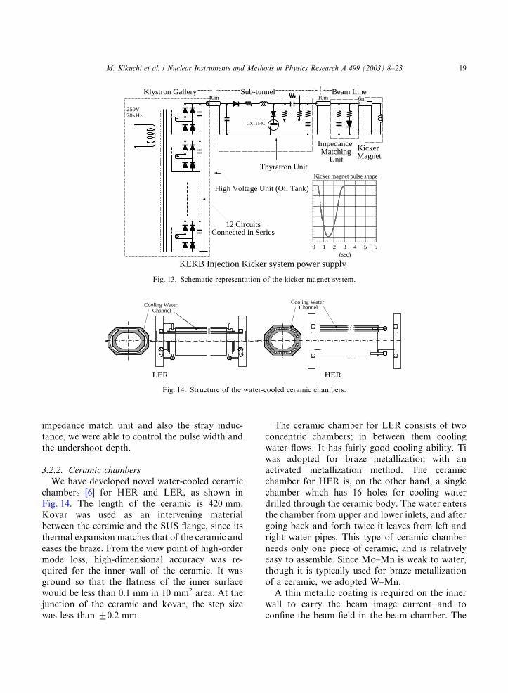
impedance match unit and also the stray induc-tance, we were able to control the pulse width andthe undershoot depth.
3.2.2. Ceramic chambers
We have developed novel water-cooled ceramicchambers [6] for HER and LER, as shown inFig. 14. The length of the ceramic is 420 mm:Kovar was used as an intervening materialbetween the ceramic and the SUS flange, since itsthermal expansion matches that of the ceramic andeases the braze. From the view point of high-ordermode loss, high-dimensional accuracy was re-quired for the inner wall of the ceramic. It wasground so that the flatness of the inner surfacewould be less than 0:1 mm in 10 mm2 area. At thejunction of the ceramic and kovar, the step sizewas less than 70:2 mm:
The ceramic chamber for LER consists of twoconcentric chambers; in between them coolingwater flows. It has fairly good cooling ability. Tiwas adopted for braze metallization with anactivated metallization method. The ceramicchamber for HER is, on the other hand, a singlechamber which has 16 holes for cooling waterdrilled through the ceramic body. The water entersthe chamber from upper and lower inlets, and aftergoing back and forth twice it leaves from left andright water pipes. This type of ceramic chamberneeds only one piece of ceramic, and is relativelyeasy to assemble. Since Mo–Mn is weak to water,though it is typically used for braze metallizationof a ceramic, we adopted W–Mn.
A thin metallic coating is required on the innerwall to carry the beam image current and toconfine the beam field in the beam chamber. The
Thyratron Unit
CX1154C
Impedance Matching
Unit
10m 6m
Kicker Magnet
40m
12 CircuitsConnected in Series
250V20kHz
High Voltage Unit (Oil Tank)
KEKB Injection Kicker system power supply
0 1 2 3 4 5 6(sec)
Kicker magnet pulse shape
Klystron Gallery Sub-tunnel Beam Line
Fig. 13. Schematic representation of the kicker-magnet system.
LER HER
Cooling Water ChannelCooling Water
Channel
Fig. 14. Structure of the water-cooled ceramic chambers.
M. Kikuchi et al. / Nuclear Instruments and Methods in Physics Research A 499 (2003) 8–23 19

thickness of the coating should be, on the otherhand, small enough so that the kicker field is notreduced too much due to an eddy current in thecoating. The power from the image current hadbeen measured in the AR under a stored current of500 mA: Extrapolating the data to the case ofKEKB, it had been estimated to be approximately1 kW for a 6 mm Ti coating to the design currentof 2:6 A: With this thickness, the power from eddycurrent was negligibly small, 20–50 W; under a50 Hz repetition rate. The inner surface was coatedwith Ti using Ti–Mn wire at the center of thechamber. The uniformity has been checked with amicroscope for cut samples. Since the chambershape is racetrack, the thickness was asymmetric; itwas relatively thicker at the upper and lower sidesand 60% thinner in the side arc.
3.2.3. Operation status
It was checked whether the kicker orbit bump isclosed, making use of a single-pass BPM of thefast-feedback system, which measures the beamposition of each bunch on a turn-by-turn basis.Fig. 15 shows snapshots of the horizontal posi-tions of each bunch around the injected bucket.Every fourth RF bucket was filled in thismeasurement. Since the location of the BPM isoutside of the kicker orbit bump, no signal wouldbe observed if the bump was closed. In the left
figure of Fig. 15, the kick angle was differentbetween the two groups of kickers. In this case, theshape of kicker pulse is imprinted on the pattern ofbunch oscillation. By adjusting the kick angle, onecan reduce the amplitude to a certain level, where,however, another type of pattern emerges, asshown in the right figure. Note that the verticalscale of the right figure is much smaller than thatof the left. This pattern could be attributed to thetime difference of the two kicker groups, and wasable to be minimized by adjusting the triggertiming of the kicker magnets to some level thatcorresponds to 1.5% of the pulse shape distortion,or 10–30 mrad kick. The temperature rise at theceramic surface was less than 11C for a LERcurrent of 950 mA and a HER current of 800 mA:
4. Beam-abort system
The beam-abort system is an important elementof KEKB for the protection of sensitive compo-nents of the Belle detectors and the acceleratorcomponents from damage due to intense beams. Itis also indispensable for radiation safety. A beam-abort trigger is issued from many acceleratorcomponents as well as Belle when their parametersof, for example, temperature or radiation dose etc.,exceeds their threshold levels.
Fig. 15. Snapshots of the horizontal position of bunches around the injected bucket. Left: pattern from kick angle error, 2 ms=div;Right: pattern from timing error, 0:5 ms=div:
M. Kikuchi et al. / Nuclear Instruments and Methods in Physics Research A 499 (2003) 8–2320
The beam-abort system is composed of two(one) horizontal kicker magnets, a vertical kicker,a Lambertson DC septum magnet and a beamdump for HER (LER). If one of the kickers fails tokick, an improperly deflected beam might hit someunexpected parts of the Belle or acceleratorcomponents and might give rise to an irrecov-erably serious damage. In order to avoid suchrisks, we adopted one common power supply forthe kickers, where only one power switch is used.
4.1. Outline of the abort system
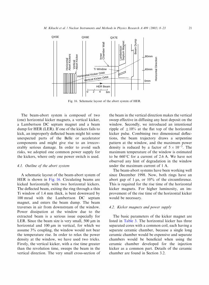
A schematic layout of the beam-abort system ofHER is shown in Fig. 16. Circulating beams arekicked horizontally with two horizontal kickers.The deflected beam, exiting the ring through a thinTi window of 1:4 mm thick, is bent downward by100 mrad with the Lambertson DC septummagnet, and enters the beam dump. The beamtraverses in air from downstream of the window.Power dissipation at the window due to theextracted beam is a serious issue especially forLER. Since the beam size is very small, 500 mm inhorizontal and 100 mm in vertical, for which weassume 3% coupling, the window would not bearthe temperature rise. In order to relax the powerdensity at the window, we have used two tricks.Firstly, the vertical kicker, with a rise time greaterthan the revolution time, sweeps the beam in thevertical direction. The very small cross-section of
the beam in the vertical direction makes the verticalsweep effective in diffusing any heat deposit on thewindow. Secondly, we introduced an intentionalripple of 710% at the flat top of the horizontalkicker pulse. Combining two dimensional deflec-tions, the beam trajectory draws a serpentinepattern at the window, and the maximum powerdensity is reduced by a factor of 5 103: Themaximum temperature of the window is estimatedto be 6601C for a current of 2:6 A: We have notobserved any hint of degradation in the windowunder the maximum current of 1 A:
The beam-abort systems have been working wellsince December 1998. Now, both rings have anabort gap of 1 ms; or 10% of the circumference.This is required for the rise time of the horizontalkicker magnets. For higher luminosity, an im-provement of the rise time of the horizontal kickerwould be necessary.
4.2. Kicker magnets and power supply
The basic parameters of the kicker magnet arelisted in Table 3. The horizontal kicker has threeseparated cores with a common coil, each having aseparate ceramic chamber, because a single longceramic chamber would be expensive and separatechambers would be beneficial when using theceramic chamber developed for the injectionkicker as a common part. Details of the ceramicchamber are found in Section 3.2.
QX5E QX6E QX7E
Hor
izon
tal
Abo
rt K
icke
rs
Ver
tical
A
bort
Kic
ker
Lam
bert
son
Sep
tum
Mag
net
Bea
m D
ump
Horizontal Kicker Orbit
Vertical Kicker Orbit
40mm
80mm
0mm
Inne
r C
ham
ber
Wal
l
Ti Window
HER Beam
0 2 4 6m
Hor
izon
tal D
irect
ion
Fig. 16. Schematic layout of the abort system of HER.
M. Kikuchi et al. / Nuclear Instruments and Methods in Physics Research A 499 (2003) 8–23 21

Fig. 17 shows a schematic representation of themain part of the power supply for the HER, whichsupplies the pulse current simultaneously to thethree kickers. The power supply for LER has thesame circuit with different parameters. The hor-izontal kickers are connected in parallel to makethe rise time shorter. The voltage ðVMAINÞ ofthe main capacitance ðCMAINÞ is 35 kV ð19 kVÞand the voltage of the capacitance ðCPCÞ is1:6 kV ð0:6 kVÞ for HER (LER). Charging circuitsare not shown in the figure. We have usedthyratrons as power switches, CX1175 andCX1154 (Marconi Applied Technologies), forHER and LER, respectively. Their maximumvoltages are 70 and 40 kV; which give a largemargin in voltage.
As the thyratron turns on, negative voltagepulse starts to travel through a cable
ðTMAINÞ 50 m long; when it reaches the otherend, the voltage of the main capacitor ðCMAINÞjumps up to 70 kV; twice the charged voltage. Thisvoltage continues for up to 500 ns: The dischar-ging current of CMAIN starts to flow throughmainly the coils of the horizontal kickers. Its risetime is determined by VMAIN and the inductance ofthe horizontal kicker ðLH). The droop of thecurrent ðIHÞ is compensated for by a dischargecurrent of CPC: On the other hand, the charge ofCV is resonantly discharged through the coil of thevertical kicker ðLVÞ: From its resonant frequency,the rise time of the current ðIVÞ is determined to beB10 ms: The ripples at the flat top of thehorizontal kicker pulse are generated while makinguse of a resonant circuit composed of CH and LH:The period is about 3:3 ms: The amplitude ofripples is about 710%:
4.3. Measurement of the magnetic fields
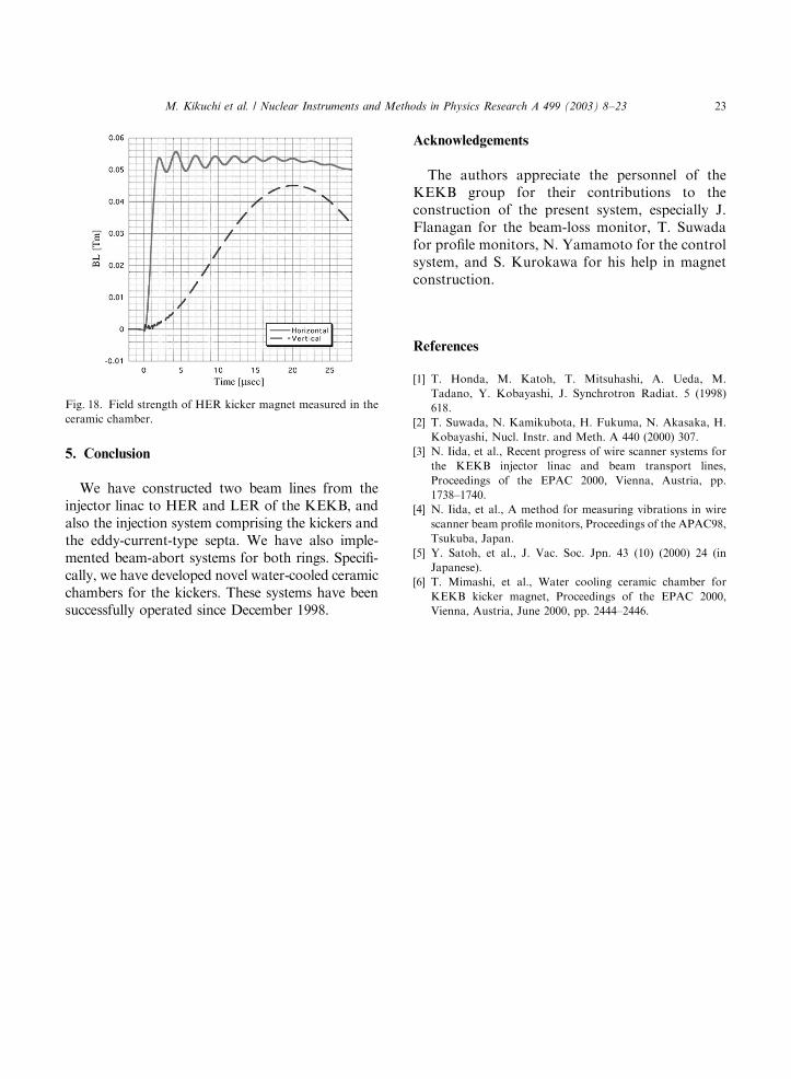
The integrated fields of kicker magnets along thebeam direction in the ceramic chambers have beenmeasured. Fig. 18 shows the results. The rise timeof the horizontal field is about 1 ms and the rippleshave sufficient amplitude during the time for a ringcircumference of 10 ms: The field strength of thehorizontal kicker satisfies the requirement inTable 3. The field strength of the verticalkicker at 10 ms is, however, 25% smaller than thevalue given in Table 3. To remedy this, we madethe rise time faster by adjusting CV; and also byadding a resistance to CV in parallel. With thesechanges the field strength has satisfied the speci-fications.
C MAIN C V
L V
C PC
T MAIN
T V25m
9µH
3µF
50 µF
1.2 µF
50m35kV
1.6kV
Power Crowbar Circuit
IH
IV
Vertical Kicker
THY
CH
L HT H
25m 6µH
48nF
under ground
Horizontal Kickers
Z 0=10 Ω
Z 0=100 Ω
Z 0=25 Ω
Fig. 17. Main circuit of power supply for the HER abort
kickers. The charging circuits are not shown.
Table 3
Parameters of kicker magnets
HER-H HER-V LER-H LER-V
Deflection angle (mrad) 1.875 1.2 1.93 1.4
Integrated field Bl (T m) 0.0525 0.0336 0.0238 0.0173
Peak magnetic filed (T) 0.05 0.0961 0.0227 0.0494
Peak current (kA) 1.79 2.68 1.62 1.23
Number of turns 2 3 1 4
Inductance in design ðmHÞ 11.4 8.64 4.4 11.6
Gap height, width (mm) 90, 160 105, 176 90, 160 125, 170
Ferrite length (mm) 900 2 300 900 300
M. Kikuchi et al. / Nuclear Instruments and Methods in Physics Research A 499 (2003) 8–2322
5. Conclusion
We have constructed two beam lines from theinjector linac to HER and LER of the KEKB, andalso the injection system comprising the kickers andthe eddy-current-type septa. We have also imple-mented beam-abort systems for both rings. Specifi-cally, we have developed novel water-cooled ceramicchambers for the kickers. These systems have beensuccessfully operated since December 1998.
Acknowledgements
The authors appreciate the personnel of theKEKB group for their contributions to theconstruction of the present system, especially J.Flanagan for the beam-loss monitor, T. Suwadafor profile monitors, N. Yamamoto for the controlsystem, and S. Kurokawa for his help in magnetconstruction.
References
[1] T. Honda, M. Katoh, T. Mitsuhashi, A. Ueda, M.
Tadano, Y. Kobayashi, J. Synchrotron Radiat. 5 (1998)
618.
[2] T. Suwada, N. Kamikubota, H. Fukuma, N. Akasaka, H.
Kobayashi, Nucl. Instr. and Meth. A 440 (2000) 307.
[3] N. Iida, et al., Recent progress of wire scanner systems for
the KEKB injector linac and beam transport lines,
Proceedings of the EPAC 2000, Vienna, Austria, pp.
1738–1740.
[4] N. Iida, et al., A method for measuring vibrations in wire
scanner beam profile monitors, Proceedings of the APAC98,
Tsukuba, Japan.
[5] Y. Satoh, et al., J. Vac. Soc. Jpn. 43 (10) (2000) 24 (in
Japanese).
[6] T. Mimashi, et al., Water cooling ceramic chamber for
KEKB kicker magnet, Proceedings of the EPAC 2000,
Vienna, Austria, June 2000, pp. 2444–2446.
Fig. 18. Field strength of HER kicker magnet measured in the
ceramic chamber.
M. Kikuchi et al. / Nuclear Instruments and Methods in Physics Research A 499 (2003) 8–23 23