Beam profiler
108
01.04.2012 1 For latest updates please visit our website: www.ophiropt.com/photonics Table of contents Page About Ophir Optronics 3 Ophir Power and Energy Meters - Versatility for Every Application 5 Calibration Capability at Ophir 6 1.0 Sensors 7 Laser Power and Energy Sensors Table of Contents 8 Sensor Finder Program 13 General Introduction 15 1.1 Power Sensors 17 Power Sensors Introduction 18 Absorption and Damage Graphs for Thermal Sensors 21 1.1.1 Photodiode Power Sensors 22 1.1.1.1 Standard Photodiode Sensors - 10pW-3W 22 1.1.1.2 Round Photodiode Sensors - 20pW-3W 25 1.1.1.3 Special Photodiode Sensors and Integrating Spheres - 50pW-3W and 20mLux-200kLux 26 1.1.2 Thermal Power Sensors 28 1.1.2.1 High Sensitivity Thermal Sensors - 30μW - 12W 28 1.1.2.2 Low Power Thermal Sensors - 20mW-150W 30 1.1.2.3 Low - Medium Power Thermal Sensors - Apertures 17mm - 35mm, 30mW-150W 32 1.1.2.4 Medium Power Large Aperture Thermal Sensors - Apertures 50mm-65mm, 100mW-300W 34 1.1.2.5 Medium - High Power Fan Cooled Thermal Sensors - 50mW-500W 36 1.1.2.6 High Power Water Cooled Thermal Sensors and Power Pucks - 1W-10kW 38 1.1.3 StarLink Direct to PC Power Sensors 42 1.1.4 Power Sensor Accessories 43 1.1.4.1 Accessories for PD300 Sensors 43 1.1.4.2 Accessories for Thermal Sensors, PD300R, 3A-IS, FPS-1 44 1.1.4.3 High Power Water Cooled and Fan Cooled Laser Beam Dumps - Up to 5kW 45 1.1.5 OEM Thermal Sensors 46 Thermal OEM Sensors - Introduction 47 1.1.5.1 Standard OEM Thermal Sensors - 20mW-300W 49 1.1.5.2 Examples of Custom OEM Power Sensor Solutions 54 1.2 BeamTrack Power/Position/Size sensors introduction 55 1.2.1 BeamTrack Power/Position/Size sensors 100μW to 10W 56 1.2.2 BeamTrack Power/Position/Size sensors 40mW to 150W 57 1.2.3 BeamTrack Power/Position/Size sensors 150mW to 400W 58 1.2.4 BeamTrack Power/Position/Size sensors Device Software Support 59 1.3 Energy Sensors 61 Energy Sensors - Introduction 62 Absorption and Damage Graphs for Pyroelectric Sensors 63 Wavelength Range and Repetition Rate for Energy Sensors 64 1.3.1 65 1.3.2 66 1.3.3 68 1.3.4 RP Sensors - 100mW - 1500W 71 1.3.5 StarLink Direct to PC Energy Sensors 73 1.3.6 Energy Sensors Accessories 74 1.3.6.1 Accessories for pyroelectric sensors 74 1.3.6.2 Fast Photodetector Model FPS-1 75 1.3.7 OEM Energy Sensors 76 OEM Sensors - Introduction 77 1.3.7.1 78 1.3.7.2 Examples of Custom OEM Energy Sensor Solutions 81 2.0 Power Meters 83 Power Meter Finder 84 Power Meters and PC Interfaces - Introduction 86 2.1 Power Meters 87 2.1.1 Vega 87 2.1.2 Nova II 89 2.1.3 LaserStar 91 2.1.4 Nova 93 2.1.5 Accessories 95 PC Connectivity Options for Power/Energy Measurement 96 Sensors 1.0 Power Meters 2.0 3.0 Beam Profile
-
Upload
refi-magazine -
Category
Documents
-
view
312 -
download
2
description
Beam profiler
Transcript of Beam profiler

01.04.2012
1
For latest updates please visit our website: www.ophiropt.com/photonics
Table of contents Page
About Ophir Optronics 3 Ophir Power and Energy Meters - Versatility for Every Application 5 Calibration Capability at Ophir 6
1.0 Sensors 7 Laser Power and Energy Sensors Table of Contents 8 Sensor Finder Program 13 General Introduction 151.1 Power Sensors 17 Power Sensors Introduction 18 Absorption and Damage Graphs for Thermal Sensors 211.1.1 Photodiode Power Sensors 221.1.1.1 Standard Photodiode Sensors - 10pW-3W 221.1.1.2 Round Photodiode Sensors - 20pW-3W 251.1.1.3 Special Photodiode Sensors and Integrating Spheres - 50pW-3W and 20mLux-200kLux 261.1.2 Thermal Power Sensors 281.1.2.1 High Sensitivity Thermal Sensors - 30µW - 12W 281.1.2.2 Low Power Thermal Sensors - 20mW-150W 301.1.2.3 Low - Medium Power Thermal Sensors - Apertures 17mm - 35mm, 30mW-150W 321.1.2.4 Medium Power Large Aperture Thermal Sensors - Apertures 50mm-65mm, 100mW-300W 341.1.2.5 Medium - High Power Fan Cooled Thermal Sensors - 50mW-500W 361.1.2.6 High Power Water Cooled Thermal Sensors and Power Pucks - 1W-10kW 381.1.3 StarLink Direct to PC Power Sensors 421.1.4 Power Sensor Accessories 431.1.4.1 Accessories for PD300 Sensors 431.1.4.2 Accessories for Thermal Sensors, PD300R, 3A-IS, FPS-1 441.1.4.3 High Power Water Cooled and Fan Cooled Laser Beam Dumps - Up to 5kW 451.1.5 OEM Thermal Sensors 46
Thermal OEM Sensors - Introduction 471.1.5.1 Standard OEM Thermal Sensors - 20mW-300W 491.1.5.2 Examples of Custom OEM Power Sensor Solutions 541.2 BeamTrack Power/Position/Size sensors introduction 551.2.1 BeamTrack Power/Position/Size sensors 100µW to 10W 561.2.2 BeamTrack Power/Position/Size sensors 40mW to 150W 571.2.3 BeamTrack Power/Position/Size sensors 150mW to 400W 581.2.4 BeamTrack Power/Position/Size sensors Device Software Support 591.3 Energy Sensors 61 Energy Sensors - Introduction 62 Absorption and Damage Graphs for Pyroelectric Sensors 63 Wavelength Range and Repetition Rate for Energy Sensors 641.3.1 651.3.2 661.3.3 681.3.4 RP Sensors - 100mW - 1500W 711.3.5 StarLink Direct to PC Energy Sensors 731.3.6 Energy Sensors Accessories 741.3.6.1 Accessories for pyroelectric sensors 741.3.6.2 Fast Photodetector Model FPS-1 751.3.7 OEM Energy Sensors 76 OEM Sensors - Introduction 771.3.7.1 781.3.7.2 Examples of Custom OEM Energy Sensor Solutions 81
2.0 Power Meters 83 Power Meter Finder 84 Power Meters and PC Interfaces - Introduction 862.1 Power Meters 872.1.1 Vega 872.1.2 Nova II 892.1.3 LaserStar 912.1.4 Nova 932.1.5 Accessories 95 PC Connectivity Options for Power/Energy Measurement 96
Sen
sors
1.0
Pow
er M
eter
s2.
03.
0Be
am P
rofil
e

2
01.04.2012 For latest updates please visit our website: www.ophiropt.com/photonics
2.2 PC Interfaces 972.2.1 Compact Juno USB Interface 972.2.2 Pulsar Multichannel and Triggered USB Interfaces 982.2.3 Quasar - Wireless Bluetooth Interface 99 Summary of Computer Options for Ophir Meters and Interfaces 1002.3 Software Solutions 1012.3.1 StarLab 1012.3.2 StarCom 1032.3.3 LabVIEW Solutions 1052.4 OEM Power Meter Solutions 1062.4.1 Examples of Custom OEM Power/Energy Meter Solutions 106
3.0 Laser Beam Profilers 1073.1 Choosing a Beam Profiler 1083.1.1 Four Basic Questions 1083.1.2 One More Question 1093.1.3 User Guide for Choosing the Optimum Beam Profiling System 1103.1.4 Benefits of Beam Profiling 1123.2 Introduction to Camera-Based Profilers 1133.2.1 BeamGage 1143.2.1.1 BeamGage - Standart Version 1143.2.1.2 BeamGage - Professional 1223.2.1.3 BeamGage - Enterprise 1223.2.1.4 Software Comparision Chart 1233.2.1.5 190-1100nm USB Silicon CCD Cameras 1313.2.1.6 190-1100nm Firewire Silicon CCD Cameras 1331.1.2.7 190-1100nm Gig-E Silicon CCD Cameras 1343.2.1.8 1440-1605nm Phosphor Coated CCD Cameras For NIR Response 1353.2.1.9 900-1700nm - InGaAs NIR Cameras 1383.2.2 13-355nm and 1.06-300µm - Pyroelectric Array Camera 1393.2.2.1 Yag Focal Spot Analyzer 1463.3 Introduction to Scanning-Slit Profilers 1483.3.1 NanoScan 1483.3.1.1 Measuring Pulsed Beams with a Slit-based Profiler 1513.3.2 NanoScan for High-Power Beam Applications 1573.4 Accessories for Beam Profiling 1593.4.1 Neutral Density Attenuators / Filters 1593.4.2 Beam Splitter and Neutral Density Filters Combo 1633.4.3 Beam Splitter 1663.4.4 Beam Expanders Microscope Objectives 1683.4.5 Beam Reducers 1703.4.6 CCTV lens for front imaging through glass or reflected surface 1713.4.7 Imaging UV lasers 1723.5 Near Field Profilers 1743.5.1 Camera Based Near-Field Profiler 1743.5.2 NanoScan Near-Field Profiler 1753.6 What is M2? 1773.6.1 Camera Based Beam Propagation Analyzer: M2 1783.6.1.1 Specifications for the M2-200s 1803.6.1.2 Model 1813.6.2 Slit-Based Beam Propagation Analyzer M2 1833.7 Integrated Laser Performance Measurements 1853.7.1 Beam Cube and BA-500 1853.8 High-Power Applications 1893.8.1 High-Power NanoScan 1893.8.2 High Power - Laser Profiler Kits for Nd: YAG 1913.8.3 High Power - Laser Profiler Kits for CO2 1923.8.4 High Power - ModeCheck - A New Method to Assure the Performance of High Power CO2 Lasers 1933.8.5 High Power - In-Line Industrial Beam Monitoring 1953.8.5.1 II-VI-CO2 Series 1953.9 Goniometric Radiometers 196 Product Index 201 Part Number Index 210
Sen
sors
1.0
Pow
er M
eter
s2.
03.
0Be
am P
rofil
e
For latest updates please visit our website: www.ophiropt.com/photonics 01.04.2012
107
Laser Beam Analysis

108
01.04.2012 For latest updates please visit our website: www.ophiropt.com/photonics
Beam
Pro
file
3.1
3.1 Choosing a Beam ProfilerA laser beam profiler will increase your chance of success anytime you wish to design or apply a laser or when you find your laser system manufacturing subsystems are not meeting specifications. You would never think of trying to build a mechanical part without a micrometer available. So why attempt to build lasers or laser systems with only a power meter? You will produce results quicker if you can measure basic things like beam width or size, beam profile and power.
We believe as Lord Kelvin said: “You cannot improve it if you cannot measure it”.
3.1.1 Four Basic QuestionsWhen choosing a laser beam profiler there are a plethora of choices to do the job, including CCD and CMOS cameras, scanning slits, InGaAs and pyroelectric arrays, pinholes, and knife edges to mention some. How does one decide which is the proper solution for one’s application and from which company to obtain the profiler system? When making the selection there are four basic questions about the laser application that one must answer.
Wavelength?The first question is: What wavelength(s) do you intend to measure? The answer to this question determines the type of detector needed, and what the most cost effective approach may be. For the UV and visible wavelength range from <193nm up to the very near infrared at around 1320nm the silicon detector has the response to make these measurements. For these wavelengths there are the largest number of cost effective solutions including CCD cameras and silicon detector-equipped scanning aperture systems. Which of these is the best will be determined by the answers to the other three questions.
For the near infrared, from 800 to 1700nm, the choices become less abundant. In the lower end of this range from 800–1320nm the CCD cameras may still work, but InGaAs arrays become necessary above 1320nm. These are quite expensive; five times the cost of the silicon detectors. Scanning slit systems equipped with germanium detectors are still quite reasonably priced, within a few hundred dollars of their silicon-equipped cousins. At the mid and far infrared wavelengths the pyroelectric arrays and scanning slits provide viable alternatives, again the best approach being determined by the answers to the subsequent questions.
Beam Size?The second question is: What beam width or spot size do you wish to measure? This question determines the profiler type. Arrays are limited by the size of their pixels. At the current state-of-the-art pixels are at best around 4µm for silicon arrays, and considerably larger with InGaAs and pyroelectric arrays. This means that a UV-NIR beam should be larger than 50µm in diameter to ensure that enough pixels are lit to make an accurate measurement. Beams smaller than this can be magnified or expanded to be measured with a camera. InGaAs pixels are around 30µm, limiting the minimum measurable beam size to around 250-300µm; pyroelectric array pixels are even larger at 85µm, meaning the beams need to be at least one millimeter to yield accurate results. Scanning slit profilers can measure with better than 2% accuracy beams that are four times the slit width or larger, putting the minimum beam sizes at around 4µm without magnification. Those investigators who want to measure their beams directly without additional optics could find this to be an advantage.
Power?The third question is: What is the power of the beam? This determines the need for attenuation, beam splitting, as well as the detector type. Array detectors, especially silicon CCD cameras will usually need attenuation when measuring lasers. Scanning slit type profilers can measure many beams directly without any attenuation, due to the natural attenuation of the slit itself. The slit only allows light to the detector as the slit passes through the beam, and then it only lets in a fraction of the total light. Arrays and knife-edge profilers, by their nature, will allow the entire beam to impact the detector at some point in the measurement, leading to detector saturation unless the beam is severely attenuated. Lasers of any wavelength with CW powers above 100mW can be measured with the pyroelectric detector-equipped scanning slit profiler, making it the easiest profiler for many applications. Scanning slit profilers can measure up to kilowatts of laser power, depending on the spot size. High power lasers in the hundreds to thousands of watts can also be profiled using the spinning or scanned wire techniques.
For latest updates please visit our website: www.ophiropt.com/photonics 01.04.2012
109
Beam
Pro
file
3.1.
2
CW or Pulsed?The final question is: Is the laser continuous wave (CW) or pulsed? Lasers that operate pulsed at repetition rates less than ~1kHz are best profiled with an array. Scanning apertures simply cannot make these measurements effectively in “real time”. CW and pulsed beams with repetition rates above ~1kHz can be measured with scanning slits if the combination of the repetition rate and the beam size are sufficient to have enough laser pulses during the transit time of the slits through the beam to obtain a good profile. Knife-edge profilers are only able to measure CW beams. Pulsed beams have other considerations, particularly pulse-to-pulse repeatability, and pulse-energy damage thresholds.
3.1.2 One More QuestionBesides these four questions about the physical nature of the laser to be measured, there is one more that needs to be asked: How accurate does the measurement need to be? Not all profilers or profiler companies are equal in this regard. Properly designed, maintained and calibrated slit profilers can provide nanometer precision for both beam width and beam position (centroid) measurements.
A state-of-the-art CCD array with 4.4µm pixels can provide a ±2% beam width accuracy for a beam larger than 50µm. Accuracy for smaller beams may be worse due to the effects of pixelation. In addition, the effects of attenuation optics, background signal and proper zeroing can have dramatic impact on the accuracy of the measurement. Cameras that are not designed specifically for profiling may be much worse due to the presence of a cover glass on the array, which should be removed for laser profiling to prevent interference fringes. Camera arrays do provide a true two-dimensional picture of the beam and will show fine structure and hot spots, which a slit may integrate out. The accuracy requirement is a question of what the data is to be used for. Accurate collimation or focus control requires the highest beam size accuracy. Checking the laser for hot spots, uniformity or beam shape may dictate that the 2D profile is more important than the absolute size measurement accuracy.
How and where a profiler is to be used is also an important consideration in the equation. Profilers used by research and development scientists are often homemade, specialized and sometimes downright “klugey.” Ease-of-use and high throughput may be of no consequence. The purpose is to characterize specific optical systems that are well understood by the investigator. On the other hand, when a profiler needs to be used on the factory floor for a manufacturing step, ease-of-use, high throughput, and reproducibility become paramount. In this case the profiler requiring the least “fiddling” is generally the best fit. Here there is a competition between the intuitive and the ease-of-use. Some people find the 2-dimensional camera array to be the most intuitive, because they can relate to the idea of “taking a picture” of the laser beam; X-Y scanning slits may seem less intuitive. For any process that uses or works with CW or high frequency pulsed lasers the scanning slit will have the advantage of measuring the beam directly, even at its focus point, without additional attenuation optics. The dynamic range of these systems is also broad enough to measure both the focused and the unfocused beam without changing the level of attenuation. Camera arrays, on the other hand will not be able to handle both levels of power density without adjustment.
Conversely, if the important aspect of the measurement is the two-dimensional image of the beam, or if the laser is pulsed at a low repetition rate, the array will be a much better solution, even if it means that there will need to be additional attenuation optics. A slit profiler will integrate out much of the fine detail of the structure of the laser beam. This means that some beams with additional mode structure will look cleaner with a slit than with a camera. A knife-edge profiler will integrate even more structure out than a slit. Knife-edge profilers can accurately measure smaller beams than either a camera or a slit, but they have very limited centroid position accuracy, generally no better than 10%.
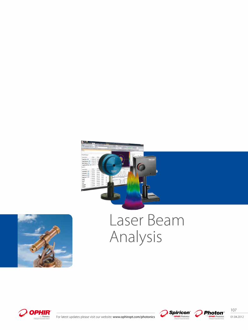
Camera-based Beam Profiler Slit-based Beam Profiler

110
01.04.2012 For latest updates please visit our website: www.ophiropt.com/photonics
Beam
Pro
file
3.1.
3
Laser Wavelength
Power MinimumBeam Size
<100mW 100mW-100W >100W <10µm <20µm>20 <50µm
>50µm >500µm >1mm
UV-Vis
NS-Si NS-Pyro HP-NS NS-Si/3.5/1.0 NS-Si/3.5/1.8 NS-Si/9/5 NS-Si/9/5 NS-Si /9/5 NS-Si /9/5
SP620 SP620 NS-Pyro NS-Pyro/9/5 NS-Pyro/9/5 NS-Pyro/9/5 NS-Pyro/9/5
SP620 SP620 SP620 SP620
NIR 1000-1100nm
SP620 NS-Pyro HP-NS NS-Ge/3.5/1.0 NS-Ge/3.5/1.8 NS-Ge/9/5 NS-Ge/9/5 NS-Ge/9/5 NS-Ge/9/5
NS-Ge SP620 NS-Pyro NS-Pyro/9/5 NS-Pyro/9/5 NS-Pyro/9/5 NS-Pyro/9/5
SP620 SP620 SP620/ SP503
Pyrocam
Telecom and Eye-Safe 1100-1800nm
NS-Ge NS-Pyro HP-NS NS-Ge/3.5/1.0 NS-Ge/3.5/1.8 NS-Ge/9/5 NS-Ge/9/5 NS-Ge/9/5 NS-Ge/9/5
NS-Pyro NS-Pyro/9/5 NS-Pyro/9/5 NS-Pyro/9/5 NS-Pyro/9/5
XEVA XEVA XEVA
Pyrocam Pyrocam
1500-1600nm
NS-Ge NS-Ge NS-Ge NS-Ge/3.5/1.0 NS-Ge/3.5/1.8 NS-Ge/9/5 NS-Ge/9/5 Pyrocam NS-Ge/9/5
SP 620-1550 SP 620-1550 SP 620-1550 SP 620-1550 XEVA SP 620-1550
Pyrocam NS-Pyro HP-NS Pyrocam w/ Beam Expansion
Pyrocam w/ Beam Expansion
NS-Pyro/9/5 NS-Pyro/9/5 NS-Pyro/9/5 NS-Pyro/9/5
MIR & FIR Pyrocam NS-Pyro Pyrocam Pyrocam
Pyrocam
ModeCheck
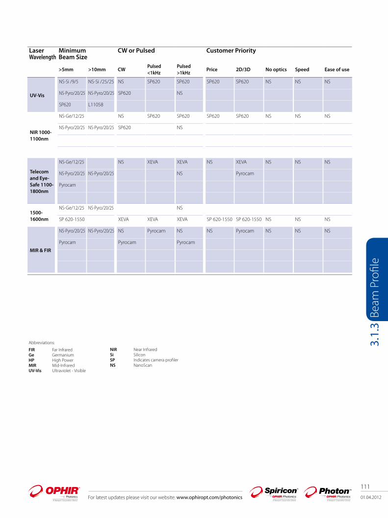
3.1.3 User Guide for Choosing the Optimum Beam Profiling System
Abbreviations:
FIR Far InfraredGe GermaniumHP High PowerMIR Mid-InfraredUV-Vis Ultraviolet - Visible
NIR Near InfraredSi SiliconSP Indicates camera profilerNS NanoScan
For latest updates please visit our website: www.ophiropt.com/photonics 01.04.2012
111
Beam
Pro
file
3.1.
3
Laser Wavelength
MinimumBeam Size
CW or Pulsed Customer Priority
>5mm >10mm CWPulsed <1kHz
Pulsed >1kHz
Price 2D/3D No optics Speed Ease of use
UV-Vis
NS-Si /9/5 NS-Si /25/25 NS SP620 SP620 SP620 SP620 NS NS NS
NS-Pyro/20/25 NS-Pyro/20/25 SP620 NS
SP620 L11058
NIR 1000-1100nm
NS-Ge/12/25 NS SP620 SP620 SP620 SP620 NS NS NS
NS-Pyro/20/25 NS-Pyro/20/25 SP620 NS
Telecom and Eye-Safe 1100-1800nm
NS-Ge/12/25 NS XEVA XEVA NS XEVA NS NS NS
NS-Pyro/20/25 NS-Pyro/20/25 NS Pyrocam
Pyrocam
1500-1600nm
NS-Ge/12/25 NS-Pyro/20/25 NS
SP 620-1550 XEVA XEVA XEVA SP 620-1550 SP 620-1550 NS NS NS
MIR & FIR
NS-Pyro/20/25 NS-Pyro/20/25 NS Pyrocam NS NS Pyrocam NS NS NS
Pyrocam Pyrocam Pyrocam
Abbreviations:
FIR Far InfraredGe GermaniumHP High PowerMIR Mid-InfraredUV-Vis Ultraviolet - Visible
NIR Near InfraredSi SiliconSP Indicates camera profilerNS NanoScan

112
01.04.2012 For latest updates please visit our website: www.ophiropt.com/photonics
Beam
Pro
file
3.1.
4
3.1.4 Benefits of Beam Profiling
You can get more out of your laser Figure 1 shows an industrial Nd: YAG laser, near Gaussian
beam, with 100 Watts output power and 1.5kW/cm2 power density. Figure 2 is the same Nd: YAG beam at greater power, 170 Watts, but it split into 2 peaks producing only 1.3kW/cm2 power density. The power density of the beam decreased 13% instead of increasing by the 70% expected. Without measuring the beam profile and beam width, you would not know what happened to your power density, and why the performance did not improve.
Laser cavities become misaligned Figures 3 & 4 are beam profiles of CO2 lasers used for
ceramic wafer scribing in the same shop. The second laser with the highly structured beam produced mostly scrap parts, until the laser cavity was aligned.
Off axis delivery optics Figures 5 & 6 show an industrial Nd:YAG laser with
misaligned turning mirror, before and after adjustment.
Alignment of devices to lenses Figures 7 & 8 show beam profiles during alignment of
a collimating lens to a laser diode. The first profile shows poor alignment of the lens to the diode, which can easily be improved when seeing the profile in real time.
Laser amplifier tuning Figures 9 & 10 show a Cr:LiSAF femtosecond laser oscillator
beam with a near Gaussian output, and what happens to the oscillator beam with poor input alignment.
All these examples illustrate the need for beam monitoring Measurement of the beam profile is needed to know if
problems exist, and the profile must be seen to make corrections.
Most laser processes can be improved, Scientific experiments can be more accurate, Commercial instruments can be better aligned, Military devices can have greater effectiveness, Industrial processing produces less scrap, Medical applications are more precise.
Just knowing the beam profile can make the difference between success and failure of a process.
5 6
87
21
9 10
43
01.04.2012
113
For latest updates please visit our website: www.ophiropt.com/photonics
Beam
Pro
file
3.2
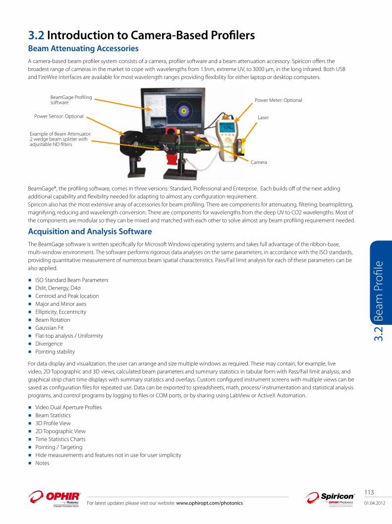
3.2 Introduction to Camera-Based Profilers Beam Attenuating AccessoriesA camera-based beam profiler system consists of a camera, profiler software and a beam attenuation accessory. Spiricon offers the broadest range of cameras in the market to cope with wavelengths from 13nm, extreme UV, to 3000 µm, in the long infrared. Both USB and FireWire interfaces are available for most wavelength ranges providing flexibility for either laptop or desktop computers.
BeamGage®, the profiling software, comes in three versions: Standard, Professional and Enterprise. Each builds off of the next adding additional capability and flexibility needed for adapting to almost any configuration requirement.Spiricon also has the most extensive array of accessories for beam profiling. There are components for attenuating, filtering, beamsplitting, magnifying, reducing and wavelength conversion. There are components for wavelengths from the deep UV to CO2 wavelengths. Most of the components are modular so they can be mixed and matched with each other to solve almost any beam profiling requirement needed.
Acquisition and Analysis SoftwareThe BeamGage software is written specifically for Microsoft Windows operating systems and takes full advantage of the ribbon-base, multi-window environment. The software performs rigorous data analyses on the same parameters, in accordance with the ISO standards, providing quantitative measurement of numerous beam spatial characteristics. Pass/Fail limit analysis for each of these parameters can be also applied.
ISO Standard Beam Parameters Dslit, Denergy, D4σ Centroid and Peak location Major and Minor axes Ellipticity, Eccentricity Beam Rotation Gaussian Fit Flat-top analysis / Uniformity Divergence Pointing stability
For data display and visualization, the user can arrange and size multiple windows as required. These may contain, for example, live video, 2D Topographic and 3D views, calculated beam parameters and summary statistics in tabular form with Pass/Fail limit analysis, and graphical strip chart time displays with summary statistics and overlays. Custom configured instrument screens with multiple views can be saved as configuration files for repeated use. Data can be exported to spreadsheets, math, process/ instrumentation and statistical analysis programs, and control programs by logging to files or COM ports, or by sharing using LabView or ActiveX Automation.
Video Dual Aperture Profiles Beam Statistics 3D Profile View 2D Topographic View Time Statistics Charts Pointing / Targeting Hide measurements and features not in use for user simplicity Notes
Laser
Power Meter: Optional
Camera
BeamGage Profilingsoftware
Power Sensor: Optional
Example of Beam Attenuator: 2 wedge beam splitter with adjustable ND filters

01.04.2012
114
For latest updates please visit our website: www.ophiropt.com/photonics
Beam
Pro
file
3.2.
1.1
3.2.1
3.2.1.1 BeamGage®-Standard Version User selectable for either best “accuracy” or “ease of use” Extensive set of ISO quantitative measurements Patented Ultracal™ algorithm for highest accuracy measurements in the industry Auto-setup and Auto-exposure capabilities for fast set-up and optimized
accuracy Statistical analysis on all calculated results displayed in real time New BeamMaker® beam simulator for algorithm self-validation
The performance of today’s laser systems can strongly affect the success of demanding, modern laser applications. The beam's size, shape, uniformity or approximation to the expected power distribution, as well as its divergence and mode content can make or break an application. Accurate knowledge of these parameters is essential to the success of any laser-based endeavor. As laser applications push the boundaries of laser performance it is becoming more critical to understand the operating criteria.
For over thirty years Ophir-Spiricon has developed instruments to accurately measure critical laser parameters. Our LBA and BeamStar software have led the way. Now with the introduction of BeamGage, Ophir-Spiricon offers the first “new from the ground up” beam profile analysis instrument the industry has experienced in over 10 years.
BeamGage includes all of the accuracy and ISO approved quantitative results that made our LBA software so successful. BeamGage also brings the ease-of-use that has made our BeamStar software so popular. Our patented UltraCal algorithm, guarantees the data baseline or “zero-reference point” is accurate to 1/10 of a digital count on a pixel-by-pixel basis. ISO 11146 requires that a baseline correction algorithm be used to improve the accuracy of beam width measurements. UltraCal has been enhanced in BeamGage to assure that accurate spatial measurements are now more quickly available.

01.04.2012
115
For latest updates please visit our website: www.ophiropt.com/photonics
Beam
Pro
file
3.2.
1.1
See Your Beam As Never Before:The Graphical User Interface (GUI) of BeamGage is new. Dockable and floatable windows plus concealable ribbon tool bars empowers the BeamGage user to make the most of a small laptop display or a large, multi-monitor desktop PC.
Dual or single monitor setup with beam displays on one and results on the other. (Note that results can be magnified large enough to see across the room).
3D displays Rotate & Tilt. All displays Pan, Zoom, Translate & Z axis Zoom.
Beam only (Note results overlaid on beam profile). Beam plus results
Multiple beam and results windows. (Note quantified profile results on 3D display & quantified 2D slices).
01.04.2012
116
For latest updates please visit our website: www.ophiropt.com/photonics
Beam
Pro
file
3.2.
1.1
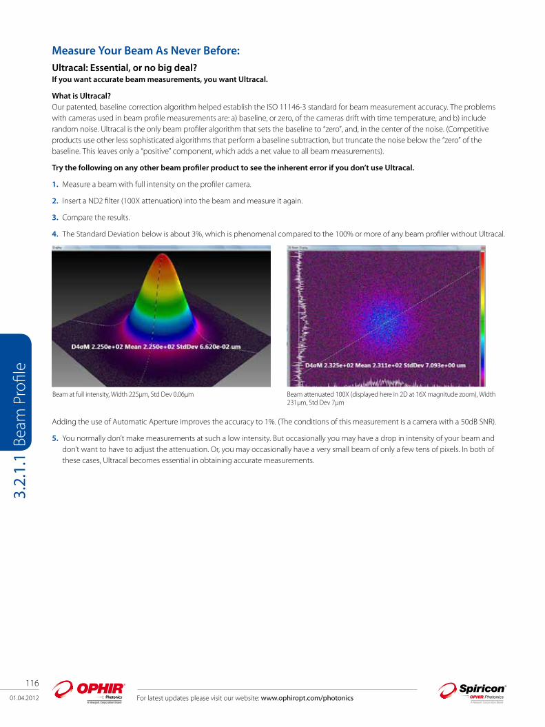
Measure Your Beam As Never Before:Ultracal: Essential, or no big deal? If you want accurate beam measurements, you want Ultracal.
What is Ultracal?Our patented, baseline correction algorithm helped establish the ISO 11146-3 standard for beam measurement accuracy. The problems with cameras used in beam profile measurements are: a) baseline, or zero, of the cameras drift with time temperature, and b) include random noise. Ultracal is the only beam profiler algorithm that sets the baseline to “zero”, and, in the center of the noise. (Competitive products use other less sophisticated algorithms that perform a baseline subtraction, but truncate the noise below the “zero” of the baseline. This leaves only a “positive” component, which adds a net value to all beam measurements).
Try the following on any other beam profiler product to see the inherent error if you don’t use Ultracal.
1. Measure a beam with full intensity on the profiler camera.
2. Insert a ND2 filter (100X attenuation) into the beam and measure it again.
3. Compare the results.
4. The Standard Deviation below is about 3%, which is phenomenal compared to the 100% or more of any beam profiler without Ultracal.
Adding the use of Automatic Aperture improves the accuracy to 1%. (The conditions of this measurement is a camera with a 50dB SNR).
5. You normally don’t make measurements at such a low intensity. But occasionally you may have a drop in intensity of your beam and don’t want to have to adjust the attenuation. Or, you may occasionally have a very small beam of only a few tens of pixels. In both of these cases, Ultracal becomes essential in obtaining accurate measurements.
Beam at full intensity, Width 225µm, Std Dev 0.06µm Beam attenuated 100X (displayed here in 2D at 16X magnitude zoom), Width 231µm, Std Dev 7µm

01.04.2012
117
For latest updates please visit our website: www.ophiropt.com/photonics
Beam
Pro
file
3.2.
1.1
Beam Measurements and StatisticsBeamGage allows you to configure as many measurements as needed to support your work, and comes standard with over 55 separate measurement choices. To distinguish between calculations that are based on ISO standards and those that are not, a graphical ISO logo is displayed next to appropriate measurements. You can also choose to perform statistical calculations on any parameter in the list.
Small sample of possible measurements out of a list of 55 Sample of calculation results with statistics applied
01.04.2012
118
For latest updates please visit our website: www.ophiropt.com/photonics
Beam
Pro
file
3.2.
1.1
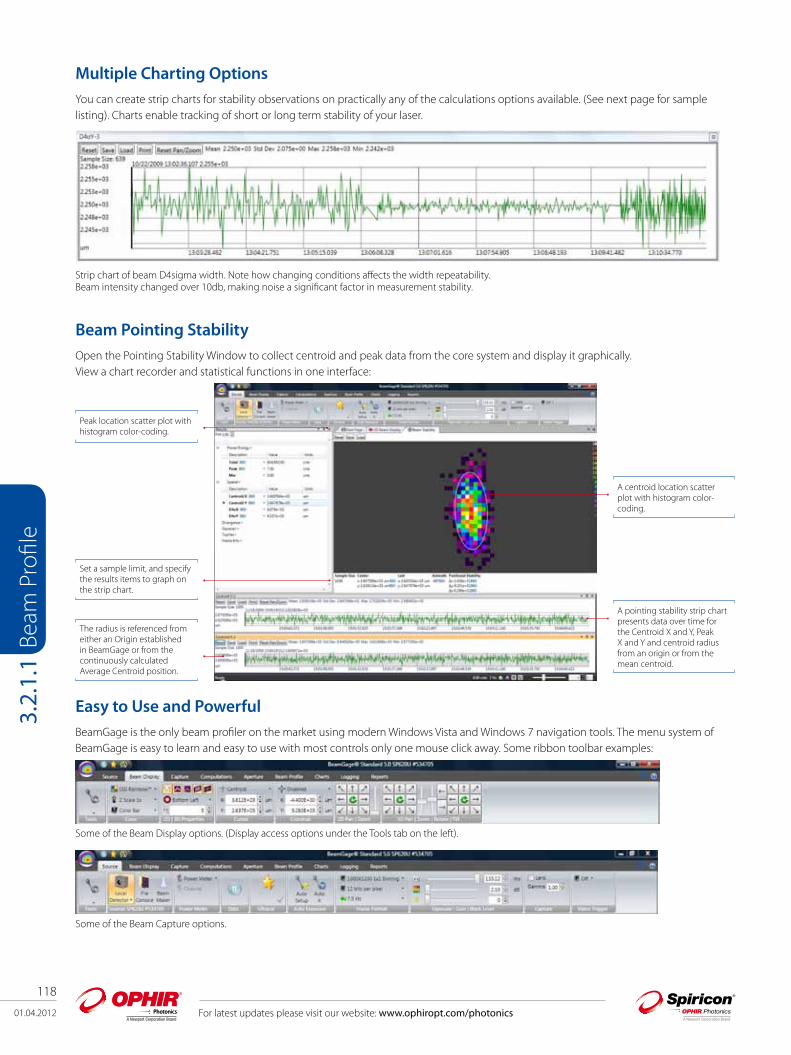
Multiple Charting OptionsYou can create strip charts for stability observations on practically any of the calculations options available. (See next page for sample listing). Charts enable tracking of short or long term stability of your laser.
Beam Pointing StabilityOpen the Pointing Stability Window to collect centroid and peak data from the core system and display it graphically. View a chart recorder and statistical functions in one interface:
Strip chart of beam D4sigma width. Note how changing conditions affects the width repeatability. Beam intensity changed over 10db, making noise a significant factor in measurement stability.
Peak location scatter plot with histogram color-coding.
Set a sample limit, and specify the results items to graph on the strip chart.
The radius is referenced from either an Origin established in BeamGage or from the continuously calculated Average Centroid position.
A centroid location scatter plot with histogram color-coding.
A pointing stability strip chart presents data over time for the Centroid X and Y, Peak X and Y and centroid radius from an origin or from the mean centroid.
Easy to Use and PowerfulBeamGage is the only beam profiler on the market using modern Windows Vista and Windows 7 navigation tools. The menu system of BeamGage is easy to learn and easy to use with most controls only one mouse click away. Some ribbon toolbar examples:
Some of the Beam Display options. (Display access options under the Tools tab on the left).
Some of the Beam Capture options.
Beam
Pro
file
01.04.2012
119
For latest updates please visit our website: www.ophiropt.com/photonics
Beam
Pro
file
3.2.
1.1
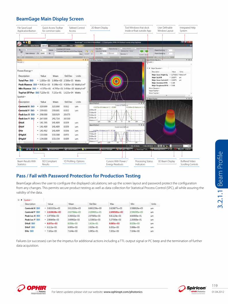
BeamGage Main Display Screen
Pass / Fail with Password Protection for Production TestingBeamGage allows the user to configure the displayed calculations; set-up the screen layout and password protect the configuration from any changes. This permits secure product testing as well as data collection for Statistical Process Control (SPC), all while assuring the validity of the data.
Failures (or successes) can be the impetus for additional actions including a TTL output signal or PC beep and the termination of further data acquisition.
File Save/LoadApplicationButton
Quick Access Toolbarfor common tasks
Tabbed ControlAccess
2D Beam Display Tool Windows that dock inside or float outside App
User Definable Window Layout
Integrated Help System
Beam Results With Statistics
ISO Compliant Results
1D Profiling Options Cursors With Power /Energy Readouts
Processing Status Indicators
3D Beam Display Buffered Video Scrolling Controls
01.04.2012
120
For latest updates please visit our website: www.ophiropt.com/photonics
Beam
Pro
file
3.2.
1.1
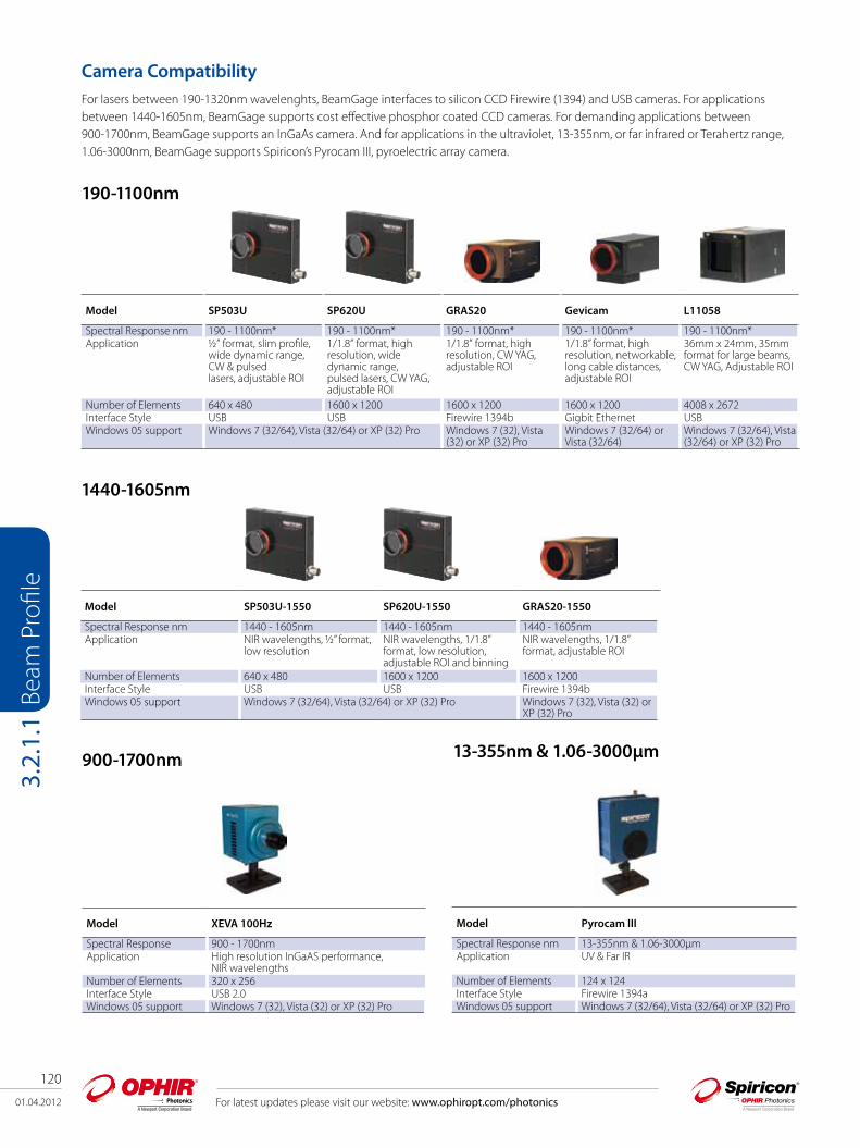
Model SP503U SP620U GRAS20 Gevicam L11058
Spectral Response nm 190 - 1100nm* 190 - 1100nm* 190 - 1100nm* 190 - 1100nm* 190 - 1100nm* Application ½” format, slim profile,
wide dynamic range, CW & pulsedlasers, adjustable ROI
1/1.8” format, high resolution, wide dynamic range, pulsed lasers, CW YAG, adjustable ROI
1/1.8” format, high resolution, CW YAG, adjustable ROI
1/1.8” format, high resolution, networkable, long cable distances, adjustable ROI
36mm x 24mm, 35mm format for large beams, CW YAG, Adjustable ROI
Number of Elements 640 x 480 1600 x 1200 1600 x 1200 1600 x 1200 4008 x 2672Interface Style USB USB Firewire 1394b Gigbit Ethernet USBWindows 05 support Windows 7 (32/64), Vista (32/64) or XP (32) Pro Windows 7 (32), Vista
(32) or XP (32) ProWindows 7 (32/64) or Vista (32/64)
Windows 7 (32/64), Vista (32/64) or XP (32) Pro
190-1100nm
Model SP503U-1550 SP620U-1550 GRAS20-1550
Spectral Response nm 1440 - 1605nm 1440 - 1605nm 1440 - 1605nmApplication NIR wavelengths, ½” format,
low resolution
NIR wavelengths, 1/1.8” format, low resolution, adjustable ROI and binning
NIR wavelengths, 1/1.8” format, adjustable ROI
Number of Elements 640 x 480 1600 x 1200 1600 x 1200Interface Style USB USB Firewire 1394bWindows 05 support Windows 7 (32/64), Vista (32/64) or XP (32) Pro Windows 7 (32), Vista (32) or
XP (32) Pro
1440-1605nm
Model XEVA 100Hz
Spectral Response 900 - 1700nmApplication High resolution InGaAS performance,
NIR wavelengthsNumber of Elements 320 x 256Interface Style USB 2.0Windows 05 support Windows 7 (32), Vista (32) or XP (32) Pro
Model Pyrocam III
Spectral Response nm 13-355nm & 1.06-3000µmApplication UV & Far IR
Number of Elements 124 x 124Interface Style Firewire 1394aWindows 05 support Windows 7 (32/64), Vista (32/64) or XP (32) Pro
900-1700nm 13-355nm & 1.06-3000µm
Camera CompatibilityFor lasers between 190-1320nm wavelenghts, BeamGage interfaces to silicon CCD Firewire (1394) and USB cameras. For applications between 1440-1605nm, BeamGage supports cost effective phosphor coated CCD cameras. For demanding applications between 900-1700nm, BeamGage supports an InGaAs camera. And for applications in the ultraviolet, 13-355nm, or far infrared or Terahertz range, 1.06-3000nm, BeamGage supports Spiricon’s Pyrocam III, pyroelectric array camera.

01.04.2012
121
For latest updates please visit our website: www.ophiropt.com/photonics
Beam
Pro
file
3.2.
1.1
BeamMaker producing a synthetically generated Hermite TEM22 beam and displayed in both 2D and 3D
Integrated automatic Help linked into the Users GuideTouch sensitive Tool tips are available on most all controls, and "What’s This" help can provide additional details. Confused about what something is or forgot how it works, just go to the top right corner and touch the "What’s This" help icon, drag it and right click on the control or menu item that you want more info about and you are taken to the explanation within the BeamGage Users Guide.
BeamMaker®; Numerical Beam Profile GeneratorBeamGage contains a utility, BeamMaker, that can synthetically generate beam profile data by modeling either Laguerre, Hermite or donut laser beams in various modal configurations. BeamMaker permits the user to model a beam profile by specifying the mode, size, width, height, intensity, angle, and noise content. Once generated the user can then compare the theoretically derived measurements to measurements including experimental inaccuracies produced by the various measurement instruments and environmental test conditions. Users can now analyze expected results and confirm if measurement algorithms will accurately measure the beam even before the experiment is constructed. BeamMaker can help laser engineers, technicians and researchers understand a beam’s modal content by calculating results on modeled beams for a better understanding of real laser beam profiles. BeamMaker is to laser beam analysis as a function generator is to an oscilloscope.
BeamGage-Standard Unique Features
Power/Energy CalibrationUsing the USB output from select Ophir power/energy meters, the BeamGage application will display measured power/energy values from the full range of Ophir thermopile, photodiode and pyroelectric sensors. Pulsed lasers can be synced up to 100Hz, or the frame rate of the triggered camera, whichever is less. This is the first time in the industry a laser power meter has been married to a laser beam profile system.
BeamGage is the only product to integrate profiling and power meter measurements
01.04.2012
122
For latest updates please visit our website: www.ophiropt.com/photonics
Beam
Pro
file
3.2.
1.2
3.2.1.2 BeamGage®-Professional
Professional is an upgrade version of BeamGage-Standard that has all of the BeamGage-Standard features plus additional functionality.
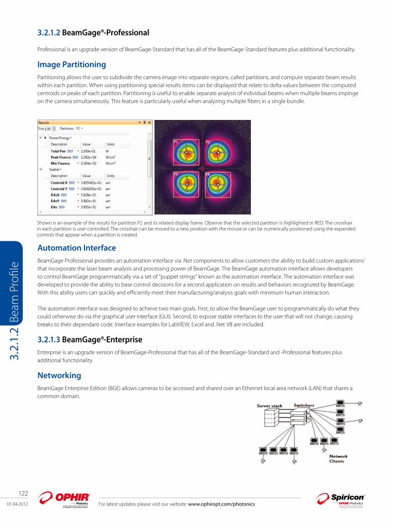
Image PartitioningPartitioning allows the user to subdivide the camera image into separate regions, called partitions, and compute separate beam results within each partition. When using partitioning special results items can be displayed that relate to delta values between the computed centroids or peaks of each partition. Partitioning is useful to enable separate analysis of individual beams when multiple beams impinge on the camera simultaneously. This feature is particularly useful when analyzing multiple fibers in a single bundle.
Automation InterfaceBeamGage Professional provides an automation interface via .Net components to allow customers the ability to build custom applications’ that incorporate the laser beam analysis and processing power of BeamGage. The BeamGage automation interface allows developers to control BeamGage programmatically via a set of “puppet strings” known as the automation interface. The automation interface was developed to provide the ability to base control decisions for a second application on results and behaviors recognized by BeamGage. With this ability users can quickly and efficiently meet their manufacturing/analysis goals with minimum human interaction.
The automation interface was designed to achieve two main goals. First, to allow the BeamGage user to programmatically do what they could otherwise do via the graphical user interface (GUI). Second, to expose stable interfaces to the user that will not change, causing breaks to their dependant code. Interface examples for LabVIEW, Excel and .Net VB are included.
3.2.1.3 BeamGage®-EnterpriseEnterprise is an upgrade version of BeamGage-Professional that has all of the BeamGage-Standard and -Professional features plus additional functionality.
NetworkingBeamGage Enterprise Edition (BGE) allows cameras to be accessed and shared over an Ethernet local area network (LAN) that shares a common domain.
Shown is an example of the results for partition P2 and its related display frame. Observe that the selected partition is highlighted in RED. The crosshair in each partition is user controlled. The crosshair can be moved to a new position with the mouse or can be numerically positioned using the expanded controls that appear when a partition is created.

01.04.2012
123
For latest updates please visit our website: www.ophiropt.com/photonics
Beam
Pro
file
3.2.
1.4
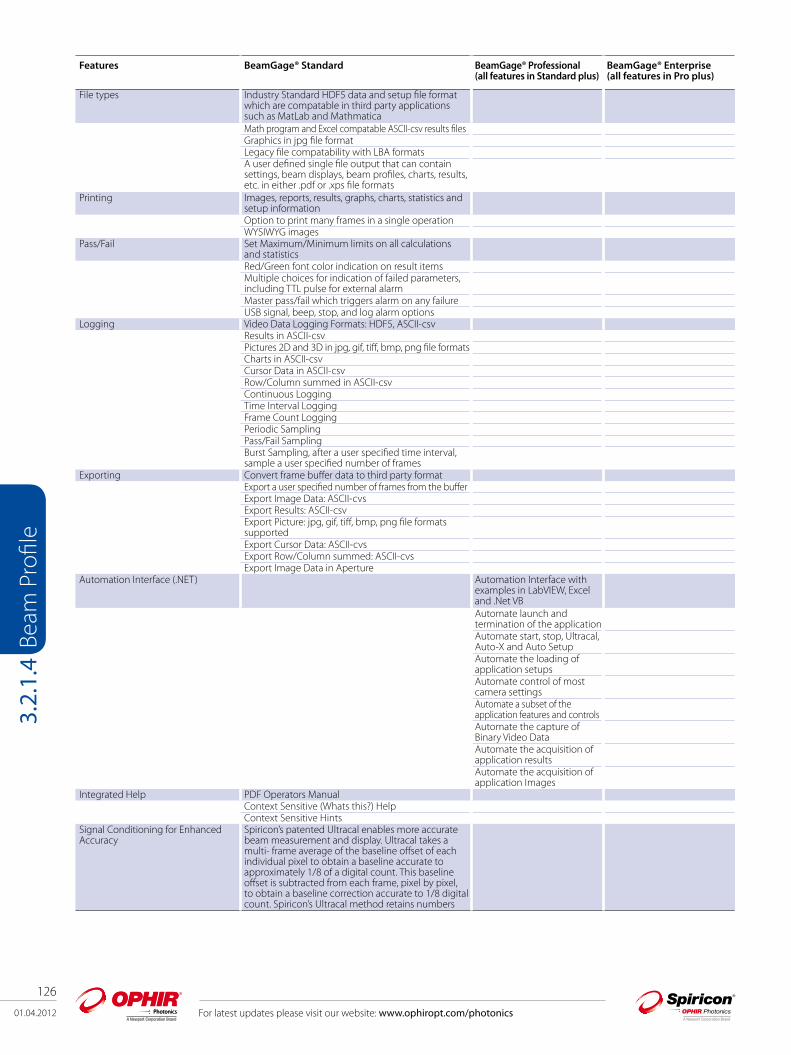
Features BeamGage® Standard BeamGage® Professional (all features in Standard plus)
BeamGage® Enterprise (all features in Pro plus)
Features Overview User selectable for either best “accuracy” or “ease of use”Supports our patented Ultracal algorithm plus Auto-setup and Auto-exposure capabilitiesExtensive set of ISO quantitative measurementsSupport for USB, Firewire and Pyrocam III cameras. Firewire cameras limited to 32bit OS only.
Supports InGaAs cameras in 32bit OS only
Supports Gig-E camera in both 32 and 64 bit OS
Support for USB, Firewire and Pyrocam III InGaAs GigENew Beam Maker® beam simulator for algorithm self validation. See below for more detailed description.Simultaneous 2D and 3D displaysMulti-instance, multi-camera use
Supports networked USB Firewire and Pyrocam III cameras. Gig-E in a future release.
Results synchronised to select models of Ophir power/energy meters. Supported products include: Vega, Nova II, Pulsar, USBI and Juno, in both 32 and 64bit OS. (Quasar is not supported)Supports Satellite windows on multiple monitorsContinuous zoom scaling in both 2D and 3D
Window partitioning to allow analysis of multiple beams on a single camera
Camera ROI support on USB and Firewire camerasManual and Auto-aperturing to reduce background effectsPass/Fail on all results items, w/multiple alarm optionsBeam Pointing Stability scatter plot and stripchart results
Full featured logging capabilities in a reloadableIndustry standard data file formatConfigurable Report Generator that allows cut and paste of results, images and settings.
NET Automation interface that.allows for remote controlExamples in LabView, Excel and .Net VB
Supports English, German, Japanese and Chinese Windows OS in both 32 and 64bit. Multilingual GUI in English, Japanes and Chinese.
Quantitative Calculations; Basic Results (per ISO 11145, 11146-1/-3, and 13694)Power/Energy Results Total power or energy (Can be calibrated or sync’d to
an external Ophir power/energy meter)Peak power/energy densityMin. FluenceAverage pulse powerPeak pulse powerDevice efficiency% in Aperture
Spatial Results Peak and Centroid locationsBeam width Second Moment (D4s) Knife Edge 90/10 Knife Edge (User selectable level) Percent of Peak (User selectable) Percent of Total Energy (User selectable) Encircled power smallest slit @ 95.4 Moving slit (User selectable)Beam diameter Average diameter (based on x/y widths) Second Moment (D4s) Encircled power smallest aperature 86.5 Encircled power smallest aperature (User selectable level)
3.2.1.4 Software Comparison Chart

01.04.2012
124
For latest updates please visit our website: www.ophiropt.com/photonics
Beam
Pro
file
3.2.
1.4
Features BeamGage® Standard BeamGage® Professional (all features in Standard plus)
BeamGage® Enterprise (all features in Pro plus)
Elliptical Results Elliptical orientation Ellipticity EccentricityDistance Measurement Cursor to Crosshair Centroid to CrosshairArea ResultsBeam cross-sectional area
Divergence Focal Length methodFar-field two-point methodFar-field Wide Angle method
Gaussian Fit 2D whole beam fits1D line fitsHeightWidth X/YCentroidGoodness of fitRoughness of fit
Tophat Results 2D and 1DFlatnessEffective AreaEffective Power/EnergyFractional Effective Power/EnergyEffective Average FluenceUniformityPlateau UniformityEdge Steepness1D or 2D surface inclination
Other Quantitative Items Frame AveragingFrame SummingFrame Reference SubtractionImage ConvolutionCamera signal/noise calculatorRow and Column summing with results loggable
Scalable Intensity Histogram, exportableX or Y axial off axis image correction
Beam Stability Displays and Results (per ISO 11670)Pointing Stabilty of Centroid Scatter Plot display w/histogram Mean Centroid Azimuth angle of the scatter Stability (M’/m’/S) Max Radius X/Y centroid/peak Strip chart plots Sample/Time controlled Pass/Fail limits Auto scaling Beam Width/Diameter Strip Charts with Results X/Y M/m beam widths plots Beam Diameter plot Mean/Std Dev/Min/Max results displayed Power/Energy Strip Charts Total Power/Energy plot Peak fluence plot Avg Power plot Elliptical Results Strip Chart Elliptical orientation plot Ellipticity plot Eccentricity plot Mean/Std Dev/Min/Max results displayed
Beam Profile Display Options Utilizes advanced hardware accelerated graphics engines. All display windows can be satellited to utilize multiple display monitors.Can open one each simulaneous 2D and 3D beam display windowsCommon color palette for 2D and 3D displaysCan open X and/or Y 1D beam slice profiles overlaid onto the 2D or 3D displays or in separate windows

01.04.2012
125
For latest updates please visit our website: www.ophiropt.com/photonics
Beam
Pro
file
3.2.
1.4
Features BeamGage® Standard BeamGage® Professional (all features in Standard plus)
BeamGage® Enterprise (all features in Pro plus)
Continuous software zooming in both 1D, 2D and 3D displaysPan to any detector locationContinuous Z axis display magnitude scaling Multiple 128 color palettes user selectableResults items can be pasted into 2D, 3D, 1D, Pointing stability or Chart display windows.
Able to partition the camera imager into multiple regions with separate results.
1D Features Available overlaid with 2D and 3D or in separate windowsX any Y plots on separate or combined displays1D displays with basic results and column row summing optionTophat 1D displays with Tophat resultsGaussian 1D displays with Gaussian fit results1D Profile display of the Gauss fit results on 1D, 2D and 3D displays
2D Features Continuously zoomable and resizable displays in satellitable windowContinuous Z axis display magnitude scaling Zoomable to subpixel resolution for origin and cursor placementsPixel boundaries delinated at higher zoom magnificationsAdjustable Cursors that can track peak or centroidAdjustable Crosshairs that can track peak or centroidAdjustable manual apertures Viewable Auto-aperture placementDisplayed beam width markerIntegrated Mouse actuated pan/zoom controlsSeparate 2D pan/zoom window to show current view in 2D beam displayManual or fixed origin placement
Ability to create partitions using the manual aperture controls
3D Features 3D graphics utilize solid surface construction with lighting and shading effectsIntegrated Mouse actuated pan/zoom/tilt/rotate controlsSelectable Mesh for drawing speed vs resolution controlContinuously zoomable and resizable displays in satellitable windowContinuous Z axis display magnitude scaling User enabled backplanes with cursor projections
Partitioning Users can subdivide the imager into separate beam measurement regions. All enabled results are computed inside of each partition
The manual aperture is used to define and create rectangular partitionWhen partitioning is enabled some new results items will be enabledCentroid measurements between beams in each partition can be performedPartitioned imagers must have a single origin common to all partitions. All coordinate results are globally referenced to this single origin
Statistical Analysis Performed on all measurement functions with on-screen display Choices of intervals Manual start/stop Time from 1 second to 1000 hours Frames from 2 to 99,999Measurements reported Current frame data, Mean, Standard Deviation, Minimum, Maximum of each calculation performedControls integrated with beam stability results, scatter and strip chart plots
01.04.2012
126
For latest updates please visit our website: www.ophiropt.com/photonics
Beam
Pro
file
3.2.
1.4
Features BeamGage® Standard BeamGage® Professional (all features in Standard plus)
BeamGage® Enterprise (all features in Pro plus)
File types Industry Standard HDF5 data and setup file format which are compatable in third party applications such as MatLab and MathmaticaMath program and Excel compatable ASCII-csv results filesGraphics in jpg file formatLegacy file compatability with LBA formatsA user defined single file output that can contain settings, beam displays, beam profiles, charts, results, etc. in either .pdf or .xps file formats
Printing Images, reports, results, graphs, charts, statistics and setup informationOption to print many frames in a single operationWYSIWYG images
Pass/Fail Set Maximum/Minimum limits on all calculations and statisticsRed/Green font color indication on result itemsMultiple choices for indication of failed parameters, including TTL pulse for external alarmMaster pass/fail which triggers alarm on any failureUSB signal, beep, stop, and log alarm options
Logging Video Data Logging Formats: HDF5, ASCII-csvResults in ASCII-csvPictures 2D and 3D in jpg, gif, tiff, bmp, png file formatsCharts in ASCII-csvCursor Data in ASCII-csvRow/Column summed in ASCII-csvContinuous LoggingTime Interval LoggingFrame Count LoggingPeriodic SamplingPass/Fail SamplingBurst Sampling, after a user specified time interval, sample a user specified number of frames
Exporting Convert frame buffer data to third party formatExport a user specified number of frames from the bufferExport Image Data: ASCII-cvsExport Results: ASCII-csvExport Picture: jpg, gif, tiff, bmp, png file formats supportedExport Cursor Data: ASCII-cvsExport Row/Column summed: ASCII-cvsExport Image Data in Aperture
Automation Interface (.NET) Automation Interface with examples in LabVIEW, Excel and .Net VB Automate launch and termination of the applicationAutomate start, stop, Ultracal, Auto-X and Auto SetupAutomate the loading of application setupsAutomate control of most camera settingsAutomate a subset of the application features and controlsAutomate the capture of Binary Video DataAutomate the acquisition of application resultsAutomate the acquisition of application Images
Integrated Help PDF Operators ManualContext Sensitive (Whats this?) Help Context Sensitive Hints
Signal Conditioning for Enhanced Accuracy
Spiricon’s patented Ultracal enables more accurate beam measurement and display. Ultracal takes a multi- frame average of the baseline offset of each individual pixel to obtain a baseline accurate to approximately 1/8 of a digital count. This baseline offset is subtracted from each frame, pixel by pixel, to obtain a baseline correction accurate to 1/8 digital count. Spiricon’s Ultracal method retains numbers

01.04.2012
127
For latest updates please visit our website: www.ophiropt.com/photonics
Beam
Pro
file
3.2.
1.4
Features BeamGage® Standard BeamGage® Professional (all features in Standard plus)
BeamGage® Enterprise (all features in Pro plus)
less than zero that result from noise when the baseline is subtracted. Retaining fractional and negative numbers in the processed signal can increase the beam width measurement accuracy by up to 10X over conventional baseline subtraction and clip level methods. Spiricon’s Ultracal conforms to the best method described in ISO 11146-3:2004.
Frame Averaging Up to 256 frames can be averaged for a signal-to-noise ratio, S/N, improvement of up to 16X (Noise is averaged up to 1/256th [8 fractional bits]). Data is processed and stored in a 32bit format.
Frame Summing Up to 256 frames can be summed to pull very weak signals out of the noise.Due to the precise nature of Ultracal baseline setting, (i.e., a retention of both positive and negative noise components) summing of frames can be performed without generating a large offset in the baseline.
Convolution (Adjacent Pixel Averaging) Choice of 5 convolution algorithms for spatial filtering for both display and calculations. Spatial filtering improves the visual S/N.
Beam Maker® Beam Maker is a new feature that allows the user to model both Laguerre-Gaussian and Hermite-Gaussian laser beams in various modal configurations. With these models you have verification and validation tools that allows not only OSI but also the end user to verify BeamGage’s basic beam width measurement algorithms. It can also be used to model laser beams with special input conditions such as signal-to-noise, background offset, and bits per pixel resolution. This allows the user to better understand the accuracy of measurements made under both optimum and adverse conditions. This tool provides the user with a method to validate algorithms against current ISO standards and methods. It can also be used to validate third party algorithms by making the output data available for use in third party applications.
Camera Features Camera features are governed by the capabilities of the various cameras that will interface with these software products, and second by which of these camera features are implimented in the software. This section will describe typical camera features supported in the application.Black Level Control (used by Ultracal and Auto-X and Auto-setup)Gain Control (used by Auto-X and Auto-setup)Exposure Control (used by Auto-X and Auto-setup)User Programmable ROIPixel Binning Pixel Sampling Bits per pixel settingExternal Trigger InputTrigger DelayStrobe OutputStrobe DelayExternal Trigger ProbeInternal Trigger Probe
Camera related features in the applications
These are features related to but not generally dependent upon the camera design. Gamma CorrectionGain CorrectionBad Pixel CorrectionLens Applied OptionPixel scale settingsMagnification settingsFrame buffer settingsUltracalEnable Auto-X (auto exposure control)Perform an Auto-Setup 8/10/12/14/16 bits per pixelSelect Format or ROIMeasure S/N ratio
Trigger, Capture and Synchronization Methods
Capture methods are features related to the application while Synchronization methods relate more to the abilities of the specific camera. NOTE: Frame capture rates are determined by many factors and are not guaranteed for any specific operating configuration.

01.04.2012
128
For latest updates please visit our website: www.ophiropt.com/photonics
Beam
Pro
file
3.2.
1.4
Features BeamGage® Standard BeamGage® Professional (all features in Standard plus)
BeamGage® Enterprise (all features in Pro plus)
Trigger modes CW - captures continuously, see Capture Options below Trigger-In from laser: Trigger pulses supplied
to the camera Strobe-Out to laser: Strobe pulses output
from the camera Video Trigger: Frame captured and displayed only when
the camera sees a signal greater than a user set levelCapture options Capture options are redefined and are approached
in a different manner than older products. The items listed below will allow for all of the previous methods but with more flexability than ever before
Results Priority: Results priority will slow the capture rate to be in sync with the computational results and display updates
Frame Priority: Frame priority will slow results and display updating to insure that frames are collected and stored in the frame buffer as fast as possible (replaces block mode)
Stop After: Will collect a set number of frames and then stop (replaces Single-Shot mode)
Periodic: Will collect frame at a programmed periodic rate
Periodic Burst: Will collect frames in a Burst at programmed periodic rates
Post processing is still available but is done via a different mechanism and is limited to only data file sources
Video Playback Video playback, post processing and post analysisUser customizable playback ratesVideo file quick pan/search controlsWhole video file playback looping with sub-selection looping Playback Video produced by loggingAlmost all measurements can be performed on video files
System Requirements PC computer running Windows7 (32/64) or XP (32) Pro Laptop or Desktop Note that some cameras require a 32bit OS. Consult factory for latest 64bit camera availability. 64bit OS required for Lw11058 camera.Not all cameras run in all Microsoft 05 versions, see ficscamera section for specificsGHz Pentium style processor, dual core recommendedMinimum 2GB RAM (4GB required for Lw11058 camera) Minimum 3-4GB RAMAccelerated Graphics ProcessorHard drive space suitable to hold the amount of video data you expect to store (50-100 GB recommended)Provision for PCI-Express, FireWire, USB2 or Gigabit Ethernet input depending on camera. Interface hardware provided with a cameras except USB2.
01.04.2012
129
For latest updates please visit our website: www.ophiropt.com/photonics
Beam
Pro
file
3.2.
1.4
Ordering Information Item Description P/N BeamGage Standard USB2 Beam Profiler Systems (camera and software) BGS-USB-SP503 BeamGage Standard software, software license, ½” format 640x480 pixel camera with 4.5mm CCD recess.
Comes with USB cable and 3 ND filters.SP90197
BGS-USB-SP503-1550 BeamGage Standard software, software license, ½” format 640x480 pixel camera with 4.5mm CCD recess. Phosphor coated to 1550 nm. Comes with USB cable and 3 ND filters.
SP90198
BGS-USB-SP620 BeamGage Standard software, software license, 1/1.8” format 1600x1200 pixel camera with 4.5mm CCD recess. Comes with USB and cable and 3 ND filters.
SP90199
BGS-USB-SP620-1550 BeamGage Standard software, software license, 1/1.8” format 1600x1200 pixel camera with 4.5mm CCD recess. Phosphor coated to 1550 nm. Comes with USB and cable, 3 ND filters.
SP90200
BeamGage Standard FireWire Beam Profiler Systems (camera and software) BGS-FWB-GRAS20,DESKTOP BeamGage Standard software, software license, 1/1.8” format 1600x1200 1394b camera with 17.5mm C-mount
recess. Comes with 1394b and trigger cable, PCI-Express interface card and 3 ND filters. Desktop model.SP90202D
BGS-FWB-GRAS20,LAPTOP BeamGage Standard software, software license, 1/1.8” format 1600x1200 1394b camera with 17.5mm C-mount recess. Comes with 1394b and trigger cable, Laptop PCI-Express interface, power supply and 3 ND filters. Laptop Model.
SP90202L
BGS-FWB-GRAS20-1550,DESKTOP BeamGage Standard software, software license, 1/1.8” format 1600x1200 Phosphor coated 1550nm sensor, 1394b camera with 17.5mm C-mount recess. Comes with 1394b and trigger cable, PCI-Express interface card and 3 ND filters. Desktop model.
SP90203D
BGS-FWB-GRAS20-1550,LAPTOP BeamGage Standard software, software license, 1/1.8” format 1600x1200 Phosphor coated 1550nm sensor 1394b camera with 17.5mm C-mount recess. Comes with 1394b and trigger cable, PCI-Express interface card and 3 ND filters. Laptop Model.
SP90203L
BeamGage Professional USB2 Beam Profiler Systems (camera and software)BGP-USB-SP503 BeamGage Professional Edition software, software license, 1/2” format 640x480 pixel camera with 4.5mm
CCD recess. Comes with USB cable and 3 ND filters.SP90236
BGP-USB-SP503-1550 BeamGage Professional Edition software, software license, 1/2” format 640x480 pixel camera with 4.5mm CCD recess. Phosphor coated 1550nm sensor. Comes with USB cable and 3 ND filters.
SP90237
BGP-USB-SP620 BeamGage Professional Edition software, software license, 1/1.8” format 1600x1200 pixel camera with 4.5mm CCD recess. Comes with USB cable and 3 ND filters.
SP90238
BGP-USB-SP620-1550 BeamGage Professional Edition software, software license, 1/1.8” format 1600x1200 pixel camera with 4.5mm CCD recess. Phosphor coated 1550nm sensor. Comes with USB cable and 3 ND filters.
SP90239
BGP-USB-L11058 BeamGage Professional Edition software, software license, 35mm format 4008x2672 pixel camera. Comes with universal power supply, USB cable and 3 ND filters.
SP90240
BGP-USB-XC130 BeamGage Professional Edition software, software license, 320x256 pixel InGaAs camera with C-mount recess. .9 to 1.7um spectral band. Comes with universal power supply, USB cable, external trigger cable and 3 ND filters (consult factory for other camera options).
SP90241
BeamGage Professional FireWire Beam Profiler Systems (camera and software) BGP-FWB-GRAS20-DESKTOP BeamGage Professional Edition software, software license, 1/1.8” format 1600x1200 pixel camera with
C-mount CCD recess. Comes with 1394b and trigger cables, PCI-Express interface card and 3 ND filters. Desktop model.
SP90242D
BGP-FWB-GRAS20-LAPTOP BeamGage Professional Edition software, software license, 1/1.8” format 1600x1200 pixel camera with C-mount CCD recess. Comes with 1394b and trigger cables, PCI-Express interface card, camera power supply, and 3 ND filters. Laptop model.
SP90242L
BGP-FWB-GRAS20-1550-DESK BeamGage Professional Edition software, software license, 1/1.8” format 1600x1200 pixel camera with C-mount CCD recess. Phosphor coated 1550nm sensor. Comes with 1394b and trigger cables, PCI-Express interface card and 3 ND filters. Desktop model.
SP90243D
BGP-FWB-GRAS20-1550-LAPTP BeamGage Professional Edition software, software license, 1/1.8” format 1600x1200 pixel camera with C-mount CCD recess. Phosphor coated 1550nm sensor. Comes with 1394b and trigger cable, PCI-Express interface card, camera power supply, and 3 ND filters. Laptop model.
SP90243L
BeamGage Enterprise USB2 Beam Profiler Systems (camera and software)BGE-USB-SP503 BeamGage Enterprise Edition software, software license, 1/2” format 640x480 pixel camera with 4.5mm
CCD recess. Comes with USB cable and 3 ND filters.SP90246
BGE-USB-SP503-1550 BeamGage Enterprise Edition software, software license, 1/2” format 640x480 pixel camera with 4.5mm CCD recess. Phosphor coated 1550nm sensor. Comes with USB cable and 3 ND filters.
SP90247
BGE-USB-SP620 BeamGage Enterprise Edition software, software license, 1/1.8” format 1600x1200 pixel camera with 4.5mm CCD recess. Comes with USB cable and 3 ND filters.
SP90248
BGE-USB-SP620-1550 BeamGage Enterprise Edition software, software license, 1/1.8” format 1600x1200 pixel camera with 4.5mm CCD recess. Phosphor coated 1550nm sensor. Comes with USB cable and 3 ND filters.
SP90249
BGE-USB-L11058 BeamGage Enterprise Edition software, software license, 35mm format 4008x2672 pixel camera. Comes with universal power supply, USB cable and 3 ND filters.
SP90250
BGE-USB-XC130 BeamGage Enterprise Edition software, software license, 320x256 pixel InGaAs camera with C-mount recess. .9 to 1.7um spectral band. Comes with universal power supply, USB cable, external trigger cable and 3 ND filters (consult factory for other camera options).
SP90251
BeamGage Enterprise Gig-E BeamProfiler Systems (camera and software)BGE-GigE-OSI182000 BeamGage Enterprise Edition software, software license, 1/1.8” format 1600x1200 pixel Gig-E camera with
C-mount CCD recess. Comes with Cat5e cable, power supply with ext trigger adapter, Ethernet destop and laptop PCI-Express cards and 3 ND filters.
SP90269
BGE-GigE-OSI182000-1550 BeamGage Enterprise Edition software, software license, 1/1.8” format 1600x1200 pixel Gig-E camera with C-mount CCD recess. Phosphor coated 1550nm sensor. Comes with Cat5e cable, power supply with ext trigger adapter, Ethernet destop and laptop PCI-Express cards and 3 ND filters.
SP90272

01.04.2012
130
For latest updates please visit our website: www.ophiropt.com/photonics
Beam
Pro
file
3.2.
1.4
Ordering Information Item Description P/N BeamGage Enterprise FireWire Beam Profiler Systems (camera and software) BGE-FWB-GRAS20-DESKTOP BeamGage Enterprise Edition software, software license, 1/1.8” format 1600x1200 pixel camera with
C-mount CCD recess. Comes with 1394b and trigger cable, PCI-Express interface card and 3 ND filters. Desktop model.
SP90252D
BGE-FWB-GRAS20-LAPTOP BeamGage Enterprise Edition software, software license, 1/1.8” format 1600x1200 pixel camera with C-mount CCD recess. Comes with 1394b and trigger cable, PCI-Express interface card, camera power supply, and 3 ND filters. Laptop model.
SP90252L
BGE-FWB-GRAS20-1550-DESK BeamGage Enterprise Edition software, software license, 1/1.8” format 1600x1200 pixel camera with C-mount CCD recess. Phosphor coated 1550nm sensor. Comes with 1394b and trigger cable, PCI-Express interface card and 3 ND filters. Desktop model.
SP90253D
BGE-FWB-GRAS20-1550-LAPTP BeamGage Enterprise Edition software, software license, 1/1.8” format 1600x1200 pixel camera with C-mount CCD recess. Phosphor coated 1550nm sensor. Comes with 1394b and trigger cable, PCI-Express interface card, camera power supply, and 3 ND filters. Laptop model.
SP90253L
Software UpgradesBEAMSTAR TO BGS UPGRADE Upgrade any BeamStar FX or SP based product to BeamGage Standard Edition. Requires a camera key to
activate. (SP cameras may require a firmware upgrade to enable ROI features).SP90219
BEAMSTAR TO BGP UPGRADE Upgrade any BeamStar FX or SP based product to BeamGage Professional Edition. Requires a camera key to activate (SP cameras may require a firmware upgrade to enable ROI features).
SP90229
BEAMSTAR TO BGE UPGRADE Upgrade any BeamStar FX or SP based product to BeamGage Enterprise Edition. Requires a camera key to activate (SP cameras may require a firmware upgrade to enable ROI features).
SP90230
LBA TO BGS UPGRADE Upgrade any LBA-FW/USB/USB-SP based product to BeamGage Standard Edition. Requires a camera key to activate (Older Pyrocam III’s require a Firmware Upgrade).
SP90210
LBA TO BGP UPGRADE Upgrade any LBA-FW/USB/USB-SP based product to BeamGage Professional Edition. Requires a camera key to activate (Older Pyrocam III’s require a Firmware Upgrade).
SP90231
LBA TO BGE UPGRADE Upgrade any LBA-FW/USB/USB-SP based product to BeamGage Enterprise Edition. Requires a camera key to activate (Older Pyrocam III’s require a Firmware Upgrade).
SP90232
BGS TO BGP UPGRADE Upgrade BeamGage Standard Edition to Professional Edition. Requires a new camera key to activate. SP90233BGS TO BGE UPGRADE Upgrade BeamGage Standard Edition to Enterprise Edition. Requires a new camera key to activate. SP90234BGP TO BGE UPGRADE Upgrade BeamGage Professional Edition to Enterprise Edition. Requires a new camera key to activate. SP90235PC Accessories for Cameras PCI-Express FireWire 1394a/b Desktop Card
PCI-Express, IEEE 1394a/b FireWire card for installation to desktop PC’s. Card has both 1394a and 1394b compatible ports. Compatible with all LBA and BeamGage FireWire systems.
SP90164
1394b FireWire Cable 1394b FireWire cable, 4.5 meter length. SP901661394a/b Adapter Cable 1394a-6 to 1394b-9 adaptor cable, 4.5 meter length. SP902071394b FireWire Power Supply External Wall cube power supply for 1394b CardBus and PCI-Express/34 Laptop Adapters. SP90167USB A-B Cable USB Cable with A to B connectors, 5 meter length. SP90204USB A-mini B Cable USB Cable with A to mini-B connectors, 5 meter length. SP90205USB-Pass/Fail Cable Output Pass/Fail signals when BeamGage is in out mode SP90060Optical Synch for Pulsed Lasers Optical Trigger for FX and SP Cameras Optical trigger assembly which can be mounted on camera or separately to sense laser pulses and
synchronize FX and SP cameras with pulses. Comes with a BNC cable.Stand for mounting sold separately.
SPZ17005
01.04.2012
131
For latest updates please visit our website: www.ophiropt.com/photonics
Beam
Pro
file
3.2.
1.5
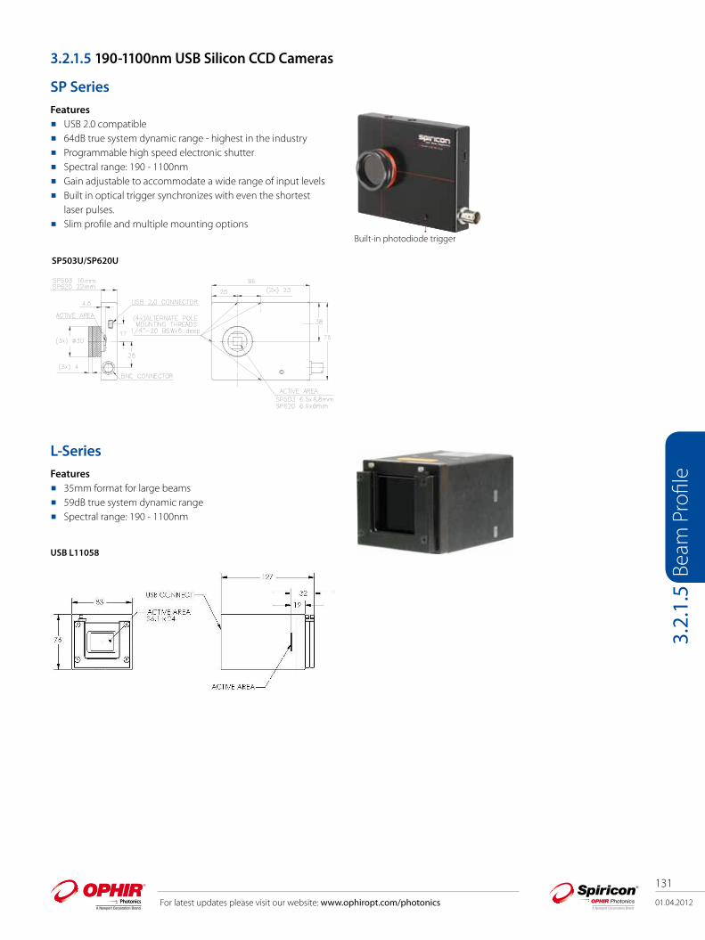
3.2.1.5 190-1100nm USB Silicon CCD Cameras
SP SeriesFeatures USB 2.0 compatible 64dB true system dynamic range - highest in the industry Programmable high speed electronic shutter Spectral range: 190 - 1100nm Gain adjustable to accommodate a wide range of input levels Built in optical trigger synchronizes with even the shortest
laser pulses. Slim profile and multiple mounting options
L-SeriesFeatures 35mm format for large beams 59dB true system dynamic range Spectral range: 190 - 1100nm
Built-in photodiode trigger
SP503U/SP620U
USB L11058

01.04.2012
132
For latest updates please visit our website: www.ophiropt.com/photonics
Beam
Pro
file
3.2.
1.5
USB Cameras for use with Laptop or Desktop PC
Item Specification
Model SP503U SP620U USB L11058
Application ½" format, slim profile, wide dynamic range, CW & pulsed lasers, adjustable ROI
1/1.8" format, high resolution, wide dynamic range, pulsed lasers, CW YAG, adjustable ROI
36mm x 24mm, 35mm format for large dia. beams, CW & pulsed lasers,ideal for CW YAG, Adjustable ROI
Spectral Response 190 - 1100nm (2) 190 - 1100nm (2) 190 - 1100nm (2)
Active Area 6.3mm W x 4.7mm H 7.1mm W x 5.4mm H 35mm x 24mmPixel spacing 9.9µm x 9.9µm 4.40µm x 4.40µm 9.0µm x 9.0µmNumber of effective pixels 640 x 480 1600 x 1200 4008 x 2672Minimum system dynamic range 64 dB 62 dB 59 dBLinearity with Power ±1% ±1% ±1%Accuracy of beam width ±2% Frame rates: In 12 bit mode 50 fps at full resolution
80 fps at 320x2407.5 fps at full resolution 28 fps at 640x48044 fps at 320x240
3.1 fps at full resolution higher rates with binning and smaller region of interest
Shutter duration 30us to multiple frame times 10us to multiple frame timesGain control 43:1 automatic or manual control 29:1 automatic or manual controlTrigger 1. BNC connector accepts positive or negative trigger. LED on camera
indicates triggering. Will synchronize with laser repetition rates up to 1KHz. Built in pre-trigger allows synchronization to even sub-nanosecond pulses
2. Same connector can provide trigger out to synch laser. Supports programmable delay on Strobe Out
3. Same connector accepts photodiode trigger (see below)
Supports both Trigger In and Strobe Out
Photodiode trigger Optional photodiode trigger available: P/N SPZ17005 N/ASaturation intensity (1) 1.3µW/cm2 2.2µW/cm2 2.2µW/cm2 0.15µW/cm2
Lowest measurable signal (1) 0.5nW/cm2 2.5nW/cm2 0.17nW/cm2
Damage threshold 50W/cm2 / 0.1J/cm2 with all filters installed for <100ns pulse width(3) 0.15mW/cm2
Dimensions and CCD recess 96mm x 76mm x 16mm CCD recess: 4.5mm below surface
96mm x 76mm x 23mm CCD recess: 4.5mm below surface
83mm x 76mm x 128mm CCD recess: 18.8mm below bezel, 31.75 from ND filter holder
Image quality at 1064nm Pulsed with trigger sync - excellentPulsed with video trigger - good CW - poor
Pulsed with trigger sync - excellentPulsed with video trigger - good CW - good
Pulsed with trigger sync - excellent Pulsed with video trigger - good CW - good
Operation mode Interline transfer progressive scan CCDSoftware supported BeamGagePC interface USB 2.0Notes: (1) Camera set to full resolution at maximum frame rate and exposure times, running CW at 632.8nm wavelength. Camera set to
minimum useful gain for saturation test and maximum useful gain for lowest signal test.(2) May be useable for wavelengths below 350nm but sensitivity is low and detector deterioration may occur. Therefore UV image converter is
recommended. Although our silicon cameras have shown response out to 1320nm it can cause significant blooming which could lead to significant errors of beam width measurement. We would suggest our XC130 InGaAs camera for these wavelengths to give you the best measurements.
(3) This is the damage threshold of the filter glass of the filters. Assuming all filters mounted with ND1 (red housing) filter in the front. Distortion ofthe beam may occur with average power densities as low as 5W/cm2.
01.04.2012
133
For latest updates please visit our website: www.ophiropt.com/photonics
Beam
Pro
file
3.2.
1.6
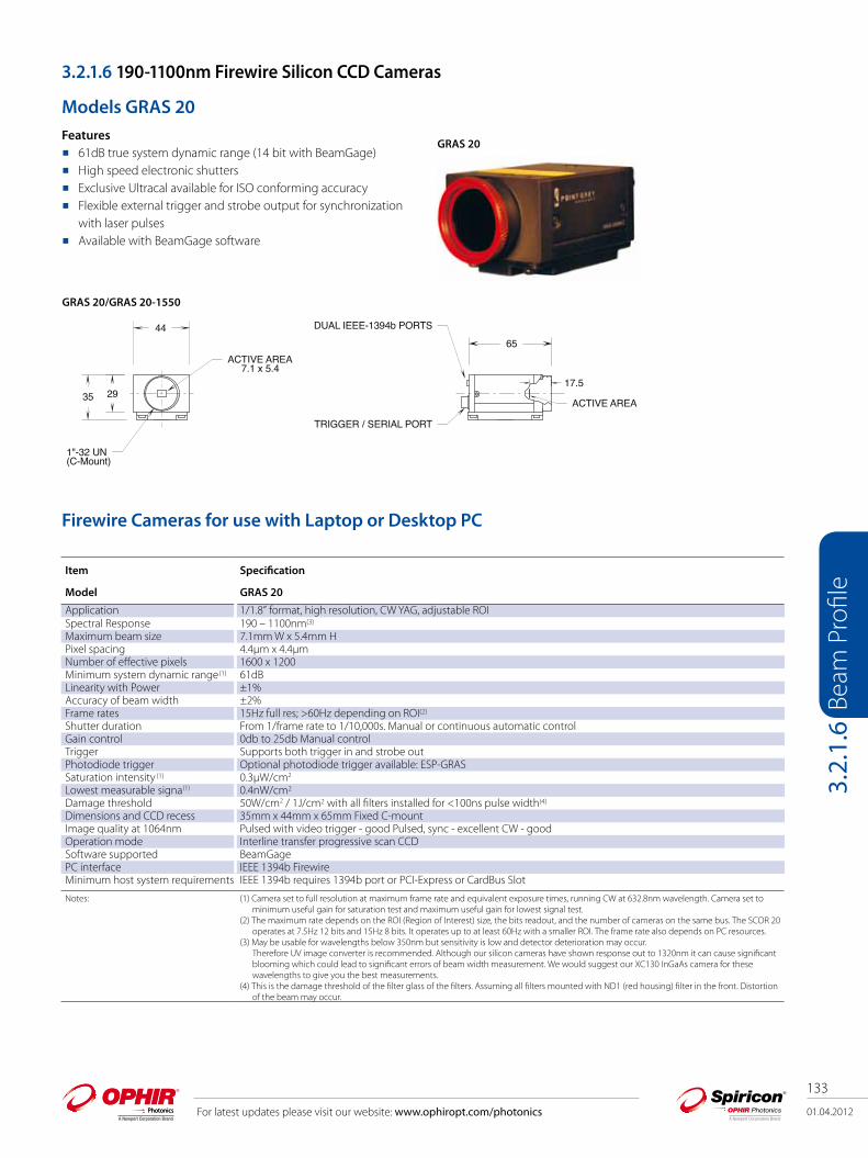
3.2.1.6 190-1100nm Firewire Silicon CCD Cameras
Models GRAS 20Features 61dB true system dynamic range (14 bit with BeamGage) High speed electronic shutters Exclusive Ultracal available for ISO conforming accuracy Flexible external trigger and strobe output for synchronization
with laser pulses Available with BeamGage software
Firewire Cameras for use with Laptop or Desktop PC
GRAS 20
Item Specification
Model GRAS 20
Application 1/1.8” format, high resolution, CW YAG, adjustable ROISpectral Response 190 – 1100nm(3)
Maximum beam size 7.1mm W x 5.4mm HPixel spacing 4.4µm x 4.4µmNumber of effective pixels 1600 x 1200Minimum system dynamic range(1) 61dBLinearity with Power ±1%Accuracy of beam width ±2%Frame rates 15Hz full res; >60Hz depending on ROI(2)
Shutter duration From 1/frame rate to 1/10,000s. Manual or continuous automatic controlGain control 0db to 25db Manual controlTrigger Supports both trigger in and strobe outPhotodiode trigger Optional photodiode trigger available: ESP-GRAS Saturation intensity (1) 0.3µW/cm2
Lowest measurable signa(1) 0.4nW/cm2
Damage threshold 50W/cm2 / 1J/cm2 with all filters installed for <100ns pulse width(4)
Dimensions and CCD recess 35mm x 44mm x 65mm Fixed C-mountImage quality at 1064nm Pulsed with video trigger - good Pulsed, sync - excellent CW - goodOperation mode Interline transfer progressive scan CCDSoftware supported BeamGagePC interface IEEE 1394b FirewireMinimum host system requirements IEEE 1394b requires 1394b port or PCI-Express or CardBus Slot
Notes: (1) Camera set to full resolution at maximum frame rate and equivalent exposure times, running CW at 632.8nm wavelength. Camera set tominimum useful gain for saturation test and maximum useful gain for lowest signal test.
(2) The maximum rate depends on the ROI (Region of Interest) size, the bits readout, and the number of cameras on the same bus. The SCOR 20operates at 7.5Hz 12 bits and 15Hz 8 bits. It operates up to at least 60Hz with a smaller ROI. The frame rate also depends on PC resources.
(3) May be usable for wavelengths below 350nm but sensitivity is low and detector deterioration may occur. Therefore UV image converter is recommended. Although our silicon cameras have shown response out to 1320nm it can cause significant blooming which could lead to significant errors of beam width measurement. We would suggest our XC130 InGaAs camera for these wavelengths to give you the best measurements.
(4) This is the damage threshold of the filter glass of the filters. Assuming all filters mounted with ND1 (red housing) filter in the front. Distortionof the beam may occur.
1"-32 UN(C-Mount)
ACTIVE AREA7.1 x 5.4
DUAL IEEE-1394b PORTS
TRIGGER / SERIAL PORT
ACTIVE AREA
17.5
6544
2935
GRAS 20/GRAS 20-1550

01.04.2012
134
For latest updates please visit our website: www.ophiropt.com/photonics
Beam
Pro
file
3.2.
1.7
3.2.1.7 190-1100nm Gig-E Silicon CCD Cameras
Models GevicamFeatures Ethernet compatible Network multiple cameras, multiple versions of BeamGage Long cable distances High speed image acquisition External trigger for synchronization with laser pulses
Firewire Cameras for use with Laptop or Desktop PC
Gevicam
Item Specification
Model Gevicam
Application 1/1.8” format, high resolution, networkable, long cable distances, adjustable ROISpectral Response 190 - 1100nm*Maximum beam size 7.16mm (H) x 5.44mm (V)Pixel spacing 4.4µm x 4.4µmNumber of effective pixels 1600 x 1200Minimum system dynamic range(1) ~57dB full speed, full resolution, min gainLinearity with Power ±1%Accuracy of beam width ±2%Frame rates 17fps @ full resolution /7.5fps optional; faster rates with binningShutter duration 60ms @ 17fps; 133ms @ 7.5fpsGain control 33dBTrigger 5V TTL 2µsec min, positive pulse, rising edge triggeredPhotodiode trigger N/ASaturation intensity (1) 0.3µW/cm2
Lowest measurable signa(1) 0.5lux @ 17fpsDamage threshold 50W/cm2 / 0.1J/cm2 with all filters installed for <100ns pulse width(3)
Dimensions and CCD recess 34mm x 34mm x 69mm CCD recess: 17.5mm below surfaceImage quality at 1064nm Pulsed with video trigger - good, Pulsed sync - excellent, CW - goodOperation mode Inline transfer progressive scanSoftware supported BeamGage - EnterprisePC interface Gigbit ethernetMinimum host system requirements PC desktop with PCI-Express slot or laptop with PCI-Express/34 slotWindows OS support Windows 7 (32/64) or Vista (32/74)Notes: (1) Camera set to full resolution at maximum frame rate and equivalent exposure times, running CW at 632.8nm wavelength. Camera set to
minimum useful gain for saturation test and maximum useful gain for lowest signal test.(2) The maximum rate depends on the ROI (Region of Interest) size, the bits readout, and the number of cameras on the same bus. The SCOR 20
operates at 7.5Hz 12 bits and 15Hz 8 bits. It operates up to at least 60Hz with a smaller ROI. The frame rate also depends on PC resources.(3) May be usable for wavelengths below 350nm but sensitivity is low and detector deterioration may occur.
Therefore UV image converter is recommended. Although our silicon cameras have shown response out to 1320nm it can cause significant blooming which could lead to significant errors of beam width measurement. We would suggest our XC130 InGaAs camera for these wavelengths to give you the best measurements.
(4) This is the damage threshold of the filter glass of the filters. Assuming all filters mounted with ND1 (red housing) filter in the front. Distortionof the beam may occur.
Gevicam

01.04.2012
135
For latest updates please visit our website: www.ophiropt.com/photonics
Beam
Pro
file
3.2.
1.8
3.2.1.8 1440-1605nm Phosphor Coated CCD Cameras For NIR Response Features 1440-1605 nm Wavelengths NIR Telecom mode field analysis NIR Laser beam analysis
Available Models USB models: SP503U-1550 SP620U-1550 Firewire models: GRAS20-1550 Analog Camera: SP-1550M
Phosphor Coating TechnologyThe up-conversion from NIR to visible light in the 1550 series cameras is nonlinear. The anti-Stokes phosphor coating produces visible photons at a rate roughly the square of the input signal. This is shown dramatically where the camera total output increases dramatically faster than a linear output shown in the bottom line. The CCD camera saturation in the center of a beam, the up-converted visible signal drops as the square of the input signal. Thus the lower signal wings of a beam are suppressed, resulting in the appearance and measurement of a beam width much smaller than actual.
This illustration is a comparison of the cross-section of a beam with and without correction. As seen, the real width of the beam is much greater than would be observed without correction.
1550nm Fiber Output 1610nm OPO Output
Cross-section of a fiber beam with and without non-linearity correction.
SP-1550M Camera: Comparison of Beam Shapewith and without Correction Factor
Mag
nitu
de in
Dig
ital C
ount
s
Beam WidthWith Correction, width=86 PixelsWithout Correction, width = 58 Pixels
Beam Width in Pixels
Non-Linearity of SP-1550M Camera at 1550nm
Out
put s
igna
l in
digi
tal c
ount
s
Total input Power in uW
Uncorrected Peak Signal
Linear From Min Signal
Non-linear output of the 1550 series cameras.
SP-1550
SP503U-1550SP620U-1550GRAS20-1550

136
01.04.2012 For latest updates please visit our website: www.ophiropt.com/photonics
Beam
Pro
file
3.2.
1.8
Wavelength ResponseThe anti-Stokes up-conversion efficiency is very wavelength dependent. This graph shows the typical spectral response curve of a new, high response coating. As seen, we have calibrated the response from 1527nm to 1605nm. We have extrapolated the shorter wavelength region by comparing our measured response to data published over the entire range.
Phosphor Coated Cameras with Spiricon's BeamGage softwareSpiricon's engineers have carefully measured the non-linearity of the signal generated by the Phosphor Coated series cameras. The software in the BeamGage incorporates an algorithm to correct for the non-linearity. This illustration shows the linearity obtained, showing in the top line that the low level signals drop linearly, rather than at the square of the input, seen in the lower line.
The two photos show the uncorrected and corrected camera beam shape in 3D. See the BeamGage section for additional information on the beam analyzer.
Signal required versus wavelength to achieve
camera full signal illumination
by anti-Stokes up conversion material.
Phosphor Coated CCD Response100
10
11460
Wavelength (nm)
mW/cm
2 fo
r Full
Vide
o
1470 1480 1490 1500 1510 1520 1530 1540 1550 1560 1570 1580 1590 1600 1610
Measured
Extrapolated fromPublished Data
Beam profile of a fiber beam with non-linearity correction.
Beam profile of a fiber beam without non-linearity correction.
SP-1550M; RS-170 monitor display when used without a frame grabber.
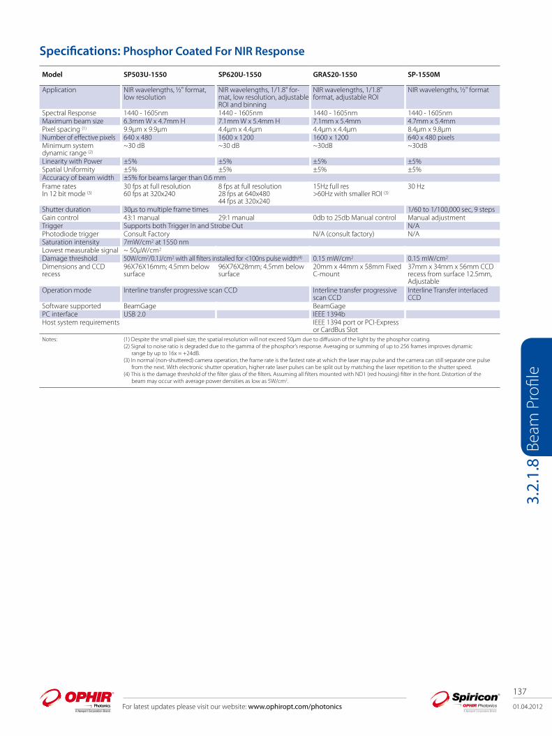
01.04.2012
137
For latest updates please visit our website: www.ophiropt.com/photonics
Beam
Pro
file
3.2.
1.8
Model SP503U-1550 SP620U-1550 GRAS20-1550 SP-1550M
Application NIR wavelengths, ½" format, low resolution
NIR wavelengths, 1/1.8" for-mat, low resolution, adjustable ROI and binning
NIR wavelengths, 1/1.8" format, adjustable ROI
NIR wavelengths, ½" format
Spectral Response 1440 - 1605nm 1440 - 1605nm 1440 - 1605nm 1440 - 1605nmMaximum beam size 6.3mm W x 4.7mm H 7.1mm W x 5.4mm H 7.1mm x 5.4mm 4.7mm x 5.4mmPixel spacing (1) 9.9μm x 9.9μm 4.4μm x 4.4μm 4.4μm x 4.4μm 8.4μm x 9.8μmNumber of effective pixels 640 x 480 1600 x 1200 1600 x 1200 640 x 480 pixelsMinimum system dynamic range (2)
~30 dB ~30 dB ~30dB ~30dB
Linearity with Power ±5% ±5% ±5% ±5%Spatial Uniformity ±5% ±5% ±5% ±5%Accuracy of beam width ±5% for beams larger than 0.6 mmFrame ratesIn 12 bit mode (3)
30 fps at full resolution60 fps at 320x240
8 fps at full resolution 28 fps at 640x48044 fps at 320x240
15Hz full res>60Hz with smaller ROI (3)
30 Hz
Shutter duration 30μs to multiple frame times 1/60 to 1/100,000 sec, 9 stepsGain control 43:1 manual 29:1 manual 0db to 25db Manual control Manual adjustmentTrigger Supports both Trigger In and Strobe Out N/APhotodiode trigger Consult Factory N/A (consult factory) N/ASaturation intensity 7mW/cm2 at 1550 nmLowest measurable signal ~ 50μW/cm2
Damage threshold 50W/cm2/0.1J/cm2 with all filters installed for <100ns pulse width(4) 0.15 mW/cm2 0.15 mW/cm2
Dimensions and CCD recess
96X76X16mm; 4.5mm below surface
96X76X28mm; 4.5mm below surface
20mm x 44mm x 58mm Fixed C-mount
37mm x 34mm x 56mm CCD recess from surface 12.5mm, Adjustable
Operation mode Interline transfer progressive scan CCD Interline transfer progressive scan CCD
Interline Transfer interlaced CCD
Software supported BeamGage BeamGagePC interface USB 2.0 IEEE 1394bHost system requirements IEEE 1394 port or PCI-Express
or CardBus SlotNotes: (1) Despite the small pixel size, the spatial resolution will not exceed 50μm due to diffusion of the light by the phosphor coating.
(2) Signal to noise ratio is degraded due to the gamma of the phosphor’s response. Averaging or summing of up to 256 frames improves dynamicrange by up to 16x = +24dB.
(3) In normal (non-shuttered) camera operation, the frame rate is the fastest rate at which the laser may pulse and the camera can still separate one pulsefrom the next. With electronic shutter operation, higher rate laser pulses can be split out by matching the laser repetition to the shutter speed.
(4) This is the damage threshold of the filter glass of the filters. Assuming all filters mounted with ND1 (red housing) filter in the front. Distortion of the beam may occur with average power densities as low as 5W/cm2.
Specifications: Phosphor Coated For NIR Response

138
01.04.2012 For latest updates please visit our website: www.ophiropt.com/photonics
Beam
Pro
file
3.2.
1.9
3.2.1.9 900-1700nm - InGaAs NIR Camera
Models XC-130 100HzFeatures NIR performance at room temperature
High resolution InGaAs array: 320x256
60dB true system dynamic range
Exclusive Ultracal for ISO conforming accuracy
Available with BeamGage software
Model XEVA XC-130 Description
Application NIR wavelengths, high resolution, ROI and binningSpectral response 900-1700nm (consult factory for other options)Element pitch 30µm squareNumber or elements 320 x 256Area 9.6 x 7.6mmLens C-mount, (Optional)Minimum system dynamic range low gain 68dB, high gain 60dBFrame rate 100 Hz (1)
Non-uniformity correction 2-Point correction plus bad pixel correction, NUC files providedSnap-shot mode Via external TTL trigger, cable providedExposure control 1us to 400 sec in Low Gain modeImager Cooling Thermoelectric cooler plus forced convection Ambient operating temperature 0 - 50° CDimensions, mm, HxWxD 111 x 87 x 107 mmWeight, camera head approx. 1.8 kgSoftware supported BeamGagePC interface USB 2.0, special cable providedNote: (1) The uncorrected rate, final corrected rate will be less.
XEVA 100Hz
90,5106,5
110,7
87,464 55
31,68
49,8 86
,05
12,3143,7
75,09
USB Cameras for use with Laptop or Desktop PC
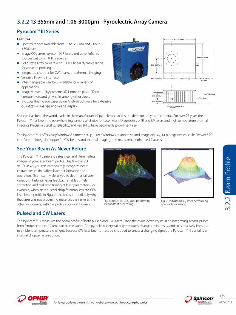
01.04.2012
139
For latest updates please visit our website: www.ophiropt.com/photonics
Beam
Pro
file
3.2.
2
3.2.2 13-355nm and 1.06-3000µm - Pyroelectric Array Camera
PyrocamTM III SeriesFeatures Spectral ranges available from 13 to 355 nm and 1.06 to >3000 µm Image CO2 lasers, telecom NIR lasers and other infrared sources out to Far IR THz sources Solid state array camera with 1000:1 linear dynamic range for accurate profiling Integrated chopper for CW beams and thermal imaging Versatile Firewire interface Interchangeable windows available for a variety of applications Image Viewer utility presents 3D isometric plots, 2D color contour plots and grayscale, among other views Includes BeamGage Laser Beam Analysis Software for extensive quantitative analysis and image display
Spiricon has been the world leader in the manufacture of pyroelectric solid-state detector arrays and cameras. For over 25 years the PyrocamTM has been the overwhelming camera of choice for Laser Beam Diagnostics of IR and UV lasers and high temperature thermal imaging. Precision, stability, reliability, and versatility have become its proud heritage.
The PyrocamTM III offers easy Win dows® camera setup, direct Windows quantitative and image display, 14 bit digitizer, versatile Firewire® PC interface, an integral chopper for CW beams and thermal imaging, and many other enhanced features.
See Your Beam As Never BeforeThe PyrocamTM III camera creates clear and illuminating im ages of your laser beam profile. Displayed in 2D or 3D views, you can immediately recognize beam characteristics that affect laser performance and operation. This instantly alerts you to detrimental laser variations. Instantaneous feedback enables timely correction and real-time tuning of laser parameters. For example, when an industrial shop foreman saw the CO2 laser beam profile in Figure 1 he knew immediately why that laser was not processing materials the same as the other shop lasers, with the profile shown in Figure 2.
Pulsed and CW LasersThe PyrocamTM III measures the beam profile of both pulsed and CW lasers. Since the pyroelectric crystal is an in tegrating sensor, pulses from femtosecond to 12.8ms can be measured. The pyroelectric crystal only measures changes in intensity, and so is relatively immune to ambient tempera ture changes. Because CW laser beams must be chopped to create a changing signal, the PyrocamTM III contains an integral chopper as an option.
Fig. 1. Industrial CO2 laser performing inconsistent processing.
Fig. 2. Industrial CO2 laser performing specifed processing.

140
01.04.2012 For latest updates please visit our website: www.ophiropt.com/photonics
Beam
Pro
file
3.2.
2
Measuring Terahertz Beam ProfilesSpiricon’s PyrocamTM III pyroelectric camera is an excel lent tool for measuring THz lasers and sources. The coating of the crystal absorbs all wavelengths including 1µm to over 3000µm (0.1THz to 300THz). For THz sources the sensitiv ity of the PyrocamTM III is relatively low, at about 300mW/cm2 at full output. With a S/N of 1000, beams of 30mW/cm2 are easily visible. In ad dition, with Spiricon’s patented Ultracal baseline setting, multiple frames can be summed to “pull” a signal out of the noise. Summing 256 frames enables viewing of beams as low as 1-2mW/cm2.
With Terahertz research suddenly being a central topic of interest, the PyrocamTM III becomes an invaluable aid in this exciting research. Otherwise, scientists working on Terahertz research have no easy way to characterize the profile, or energy distribution, of their lasers or sources.
Broad Wavelength ResponseThe PyrocamTM III detector array has a very broadband coating which enables operation at essentially all IR and UV laser wavelengths. The curve ends at 100nm in the UV, but X-ray operation has been observed. Likewise the curve ends at 100µm in the far IR, but the camera has been used at >3000µm.
Thus you can use the PyrocamTM III in the near IR for Nd:YAG lasers at 1.06µm, and for infrared fiber optics at 1.3µm and 1.55µm. Use the PyrocamTM III for HF/DF lasers near 4µm and for Optical Parametric Oscilla tors from 1 µm to 10µm. It measures Free Electron Lasers between 10µm and 3000µm. The PyrocamTM III is extremely useful in the UV from 355nm to 157nm for Excimer lasers and for tripled or quadrupled Nd:YAG lasers. The detector is stable under UV illumination, without the deterioration experienced by CCD cameras. (The pyroelectric detector operates in the visible spectrum, and can see the alignment HeNe used with CO2 lasers. However, spurious response from the underlying silicon multiplexer creates undesirable performance, and the camera is not recommended for quantitative visible measurements).
THz laser beam at 0.2THz (1.55mm) 3mW input power; 19 frames summed.
THz laser beam at 1.6THz (184µm). Free Electron laser at 100µm.Output of infrared fiber optic.Er:YAG laser at 2.9µm.
Fig. 6. Spectral response of PyrocamTM III detector array without window.

01.04.2012
141
For latest updates please visit our website: www.ophiropt.com/photonics
Beam
Pro
file
3.2.
2
Windows® PC InterfaceThe PyrocamTM III Windows application incorporates setup software to control all functions of the camera, such as pulsed versus chopped operation, gain, and background reference subtraction, eliminating all controls from the camera housing.
Windows Image ViewerA Windows viewer application enables viewing of the laser beam in a number of modes, including 3D isometric plots, 2D color contour plots, and gray scale for thermal imaging. This application enables stand-alone operation of the camera independent of any other software. Nevertheless, the Spiricon BeamGage beam analysis software provides many additional features and capabilities not incorporated with the camera.
Hybrid Integrated Circuit SensorThe PyrocamTM III consists of a LiTa03 pyroelec tric crystal mounted with indium bumps to a solid-state readout multiplexer. This sensor, developed for the Pyrocam I, has proven to be the most rugged, stable, and precise IR detector array available. Light impinging on the pyroelectric crystal is absorbed and converted to heat, which creates charge on the surface. The multiplexer then reads out this charge onto the video line. For use with short laser pulses, the firmware of the camera creates a very short electronic shutter to accurately capture the thermally generated signal.
PyrocamTM III Windows setup menu.
Composite Excimer LASIK beam profile at 193nm.
Composite Excimer LASIK beam profile in 2D display.
PyrocamTM III sensor array and window assembly

142
01.04.2012 For latest updates please visit our website: www.ophiropt.com/photonics
Beam
Pro
file
3.2.
2
State-Of-The-Art ElectronicsThe camera features a 14 bit A/D converter which digitizes deep into the camera noise. This enables reliable measurement and analysis of both large signals and low level signals in the wings of the laser beam. Fourteen bit digitizing also enables accurate signal summing and averag ing to pull weak signals out of noise. This is especially useful with fiber optics at 1.3µm and 1.55µm, and in thermal imag ing.
The PyrocamTM III camera electronics incorporates 2 Firewire® (IEEE 1394A) interface ports. Multiple Pyrocam IIIs can be daisy chained together using the 1394 cabling.
New Housing & ChopperThe PyrocamTM III incorporates a new compact housing measuring only 5.5” high by 5.1” wide, and 2.5” deep in the direction of the beam path. This allows the camera to be in serted into smaller spaces on the optical table. It also makes the camera useful as a portable camera for thermal imaging and on-site field service of laser systems. The PyrocamTM III integral focal plane chopper helps keep the camera head compact.
Applications Of The PyrocamTM IllThe PyrocamTM III is an ideal camera for use in scientific laboratory investigation of laser beams. This includes physics, chemistry, and electronic system designs. As an example, the photos below show a research CO2 laser and a research Nd:YAG laser, both with cavity misalignment. The camera is also useful in product engineering of CO2 and other infrared lasers. The PyrocamTM III is an integral part of the assembly lines of many CO2 laser manufacturers. Integrators of systems are using the PyrocamTM sensor to make sure that optical systems are aligned and operating properly.
There are many medical applications of the PyrocamTM III, such as the analysis of excimer lasers used for eye surgery. In many cases these lasers need alignment to ensure that the eye surgery is performed as expected. Other medical IR lasers perform dermatology, for which the uniformity of the beam profile must be assured. Fiber optic communications, at 1.3µm and 1.55µm make significant use of the PyrocamTM III for analyzing the beams being emitted, as well as analyzing properties of the beams before launching them into fibers. The greater stability of the PyrocamTM III make it a good choice over other cameras operating at telecommunication wavelengths.
Nd:YAG laser with cavity misalign ment.CO2 laser with cavity misalignment.
Nd:YAG laser with cavity misalign ment.CO2 laser with cavity misalignment.
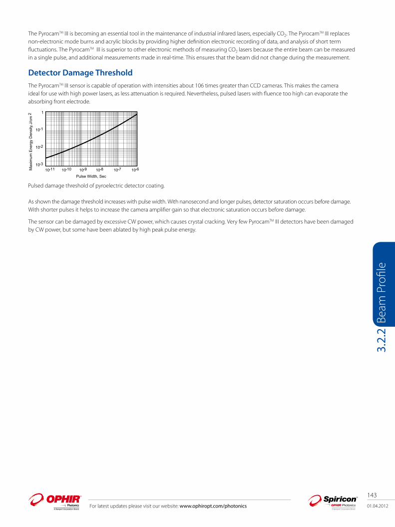
01.04.2012
143
For latest updates please visit our website: www.ophiropt.com/photonics
Beam
Pro
file
3.2.
2
The PyrocamTM III is becoming an essential tool in the maintenance of industrial infrared lasers, especially CO2. The PyrocamTM III replaces non-electronic mode burns and acrylic blocks by providing higher definition electronic recording of data, and analysis of short term fluctuations. The PyrocamTM III is superior to other electronic methods of measuring CO2 lasers because the entire beam can be measured in a single pulse, and additional measurements made in real-time. This ensures that the beam did not change during the measurement.
Detector Damage ThresholdThe PyrocamTM III sensor is capable of operation with intensities about 106 times greater than CCD cameras. This makes the camera ideal for use with high power lasers, as less attenuation is required. Nevertheless, pulsed lasers with fluence too high can evaporate the absorbing front electrode.
As shown the damage threshold increases with pulse width. With nanosecond and longer pulses, detector saturation occurs before damage. With shorter pulses it helps to increase the camera amplifier gain so that elec tronic saturation occurs before damage.
The sensor can be damaged by excessive CW power, which causes crystal cracking. Very few PyrocamTM III detec tors have been damaged by CW power, but some have been ablated by high peak pulse energy.
Pulsed damage threshold of pyroelectric detector coating.
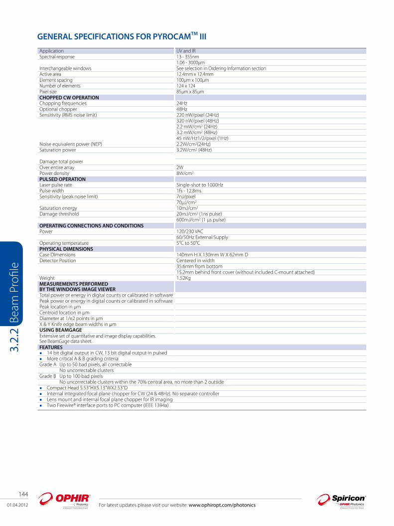
144
01.04.2012 For latest updates please visit our website: www.ophiropt.com/photonics
Beam
Pro
file
3.2.
2
GENERAL SPECIFICATIONS FOR PYROCAMTM III
Application UV and IRSpectral response 13 - 355nm
1.06 - 3000µmInterchangeable windows See selection in Ordering Information sectionActive area 12.4mm x 12.4mmElement spacing 100µm x 100µmNumber of elements 124 x 124Pixel size 85µm x 85µmCHOPPED CW OPERATION Chopping frequencies 24HzOptional chopper 48HzSensitivity (RMS noise limit) 220 nW/pixel (24Hz)
320 nW/pixel (48Hz) 2.2 mW/cm2 (24Hz) 3.2 mW/cm2 (48Hz) 45 nW/Hz1/2/pixel (1Hz)
Noise equivalent power (NEP) 2.2W/cm2(24Hz) Saturation power 3.2W/cm2 (48Hz)
Damage total powerOver entire array 2WPower density 8W/cm2
PULSED OPERATION Laser pulse rate Single-shot to 1000HzPulse width 1fs - 12.8msSensitivity (peak noise limit) 7nJ/pixel
70µJ/cm2
Saturation energy 10mJ/cm2
Damage threshold 20mJ/cm2 (1ns pulse)600mJ/cm2 (1 µs pulse)
OPERATING CONNECTIONS AND CONDITIONS Power 120/230 VAC
60/50Hz External SupplyOperating temperature 5°C to 50°CPHYSICAL DIMENSIONS Case Dimensions 140mm H X 130mm W X 62mm D Detector Position Centered in width
35.6mm from bottom 15.2mm behind front cover (without included C-mount attached)
Weight 1.52KgMEASUREMENTS PERFORMED BY THE WINDOWS IMAGE VIEWER Total power or energy in digital counts or calibrated in software Peak power or energy in digital counts or calibrated in software Peak location in µm Centroid location in µm Diameter at 1/e2 points in µm X & Y Knife edge beam widths in µmUSING BEAMGAGEExtensive set of quantitative and image display capabilities. See BeamGage data sheet.FEATURES 14 bit digital output in CW, 13 bit digital output in pulsed More critical A & B grading criteriaGrade A Up to 50 bad pixels, all correctable No uncorrectable clusters Grade B Up to 100 bad pixels No uncorrectable clusters within the 70% central area, no more than 2 outside Compact Head 5.53”HX5.13”WX2.53”D Internal integrated focal plane chopper for CW (24 & 48Hz). No separate controller Lens mount and internal focal plane chopper for IR imaging Two Firewire® interface ports to PC computer (IEEE 1394a)

01.04.2012
145
For latest updates please visit our website: www.ophiropt.com/photonics
Beam
Pro
file
3.2.
2
GENERAL SPECIFICATIONS FOR PYROCAMTM III
Ordering Information Item Description P/N Pyrocam III Beam Profiler Systems PY-III-P-A Pyroelectric array detector, pulsed only, Grade A, two FireWire ports, and basic viewer software. BeamGage
Standard included. To complete this order, you must add an Interchangeable Window part number to accompany this system (see below).
SP90090
PY-III-P-B Pyroelectric array detector, pulsed only, Grade B, two FireWire ports, and basic viewer software. BeamGage Standard included. To complete this order, you must add an Interchangeable Window part number to accompany this system (see below).
SP90091
PY-III-C-A Pyroelectric array detector, chopped and pulsed, Grade A, two FireWire ports, and basic viewer software. BeamGage Standard included. To complete this order, you must add an Interchangeable Window part number to accompany this system (see below).
SP90092
PY-III-C-B Pyroelectric array detector, chopped and pulsed, Grade B, two FireWire ports, and basic viewer software. BeamGage Standard included. To complete this order, you must add an Interchangeable Window part number to accompany this system (see below).
SP90093
Interchangeable Windows for Pyrocam III (one included free with the purchase of a Pyrocam III Beam Profiler System) PY-III-W-BK7-1.064 Pyrocam III Window BK7 A/R coated to 1064nm SP90101 PY-III-W-Si-1.05-2.5 Pyrocam III Window Silicon A/R coated to 1.05 - 2.5µm SP90102 PY-III-W-Si-2.5-4 Pyrocam III Window Silicon A/R coated to 2.5 - 4µm SP90103 PY-III-W-Ge-3-5.5 Pyrocam III Window Germanium A/R coated to 3 - 5.5µm SP90104 PY-III-W-Ge-10.6 Pyrocam III Window Germanium A/R coated to 10.6µm SP90105 PY-III-W-Ge-8-12 Pyrocam III Window Germanium A/R coated to 8 - 12µm SP90106 PY-III-W-ZnSe-10.6 Pyrocam III Window Zinc Selenide A/R coated to 10.6µm SP90107 PY-III-W-ZnSe-2-5 Pyrocam III Window Zinc Selenide A/R coated to 2 - 5µm SP90108 PY-III-W-Poly-THz Pyrocam III Window Polyethylene uncoated for Tera-Hz wavelengths SP90208
FEATURES Firewire to PCI adapter Windows image viewer
2D and 3D beam display Readout externally calibratable for energy or power Frame averaging and summing for low level signal analysis Data logging Manual gain setting Plus calculations previously provided X & Y width Centroid location Peak location Total power or energy in digital counts
Windows setup menu (control console - no buttons or knobs, more user friendly) High speed, up to 1kHz standard Automatic lock in to pulse trigger rate Programmable exposure time (to reduce signal loss from thermal spread) 50µs to 12.8ms in 50µs increments Slider for fine adjustment gain settings; 1X to 10X CW, 6X Pulse User enabled bad pixel correction Separate bad pixel correction for pulsed and CW User enabled gain correction - separate for pulsed and CW Internet field upgradeable firmware Interface to 3rd party software via ActiveX Export images in .bmp or ASCII file format

146
01.04.2012 For latest updates please visit our website: www.ophiropt.com/photonics
Beam
Pro
file
3.2.
2.1
3.2.2.1 YAG Focal Spot Analyzer Image focal spots down to 25µm in size For laser powers up to 400W (additional external ND filters required) Measure how focal distance shifts with power Can measure systems with focal length as short as 50mm Modular design allows flexibility in use C-mount, compact laser beam sampler/attenuator for camera based laser beam profiling systems High damage threshold optics for measuring energetic sources Produces undistorted sample of laser under test Adjustable attenuation maximizes system dynamic range Up to 1 x 10⁻¹⁰ attenuation available (without external filters)
Measure the focal spot of a relatively high power laser, in particular a YAG laser. The average power can be from <1 to 400 Watts and the focal spot can be as small as 25µm. The FSA can also be used to measure how the focal spot shifts with power.
The lasers focal length from the lens to the focal spot is usually on the order of 70 to 120mm. The YAG FSA assembly adds a negative lens to the LBS-300 beam splitter assembly to increase the focal path and at the same time enlarge the image. Several focal length lenses are available to accommodate different host system focal paths. The FSA includes; user selectable negative lens, 2 beam splitters, a removable beam block on the 2nd splitter, and user selectable attenuation filters prior to the beam entering the camera. An excel spreadsheet is downloadable from our website that calculates which lenses are available to use for your application, how far to mount the FSA from your focusing lens in order to see the focal spot and what the magnification of the image will be.
Operation:The FSA is mounted to the camera as shown. Then the assembly is placed below the final focusing lens of the laser at the recommended distance. The focal spot is found by moving the assembly closer and farther from the beam until the smallest spot size is seen. The exact magnification factor (usually 2-3 times) is calculated by moving the stage holding the FSA assembly a given lateral distance and seeing how far the centroid of the focal spot moves in the beam profiling software. This scaling factor is then entered into the software. In order to find focal spot shift with laser power, simply find focal spot at one power, change the power and measure how far the stage has to be moved up or down to get to the smallest beam size again.
Focal Spot Assembly Looking from camera mounting position
Focal Spot Assembly showing various beam paths
Incoming Beam
Negative lens
LBS-300
Camera
1st Output Beam; either to power meter or to Beam Dump
2nd Output Beam; built-in beam block
User selectable ND filters for attenuating input to the camera

01.04.2012
147
For latest updates please visit our website: www.ophiropt.com/photonics
Beam
Pro
file
3.2.
2.1
Ordering InformationItem Description P/N YAG Focal Spot AnalyzerYAG Focal Spot Analyzer assembly requires 1 each LBS-300-NIR and 1 each Negative LensLBS-300-NIR Beam splitter and attenuators; beam split 2 times SP90185FSA-50Y Negative lens; -50 mm YAG SP90187FSA-100Y Negative lens; -100 mm YAG SP90188FSA-125Y Negative lens; -125 mm YAG SP90189FSA-150Y Negative lens; -150 mm YAG SP90190FSA-200Y Negative lens; -200 mm YAG SP90191 AccessoriesWVF-300 ND filters; variable wedge. Replaces fixed value filter slides SP90195BD-040-A Beam Dump; 40 Watts max. power, air cooled SP90192BD-500-W Beam Dump; 500 Watts max. power, water cooled SP90193
65µm diameter focal spot Focal spot shape changing with laser power level
Examples of Usage
Specifications
Model YAG Focal Spot Analyzer
Wavelength 1064nmWedge Material BK7Wedge Coating AR ≤1%Clear aperture 17.5mmWedge ND value, each ND ≥2ND Filters Bulk NDND Values, nominal 0.3, .7, 1.0, 2.0, 3.0, 4.0 (Red holders)Filter Slides 3Filter Damage (1) 50 W/cm2
1J/cm2, 10ns pulseNegative Lens FSA-50YTo add FSA capability -50mm YAG
FSA-100Y-100mm YAGFSA-125Y-125mm YAGFSA-150Y-150mm YAGFSA-200Y-200mm YAG
AccessoriesVariable Wedge ND Filter kit WVF-300Beam Dumps BD-040-A, 40 Watts Max Power, Air Cooled
BD-500-W, 500 Watts Max Power, Water CooledNote: (1) ND bulk absorbing filters damage threshold is 50W/cm2 but should be used at <5W/cm2 to avoid thermal lensing effects.

148
01.04.2012 For latest updates please visit our website: www.ophiropt.com/photonics
Beam
Pro
file
3.3
3.3 Introduction to Scanning-Slit ProfilersThe scanning slit beam profiler moves a narrow slit in front of a photo-detector through the beam under analysis. Light passing through the slit onto the detector creates a photo-induced current in the detector. The slit acts as a physical attenuator in the scanning slit beam profiler, and the amplification gain on the detector can be set to avoid detector saturation for most beam profiling. A digital encoder precisely measures slit position. The photo-induced current is then plotted as a function of slit position to determine a linear profile of the beam. From this linear profile, important spatial information such as beam width, beam position, beam quality, and other characteristics are determined. This technique can accommodate a wide variety of test conditions.
Because slit scanners measure beams at high powers with little or no attenuation, they are ideal to profile beams used in material processing. Carbon dioxide (CO2
) lasers are widely used in materials processing, and have a 10.6 micron wavelength that cannot be profiled with most cameras. Slit scanners, therefore, provide an convenient means of measuring high-resolution CO
2 lasers with powers up to and exceeding
1000 watts.

01.04.2012
149
For latest updates please visit our website: www.ophiropt.com/photonics
Beam
Pro
file
3.3.
1
3.3.1 NanoScan
The most versatile and flexible beam profiling system availablePhoton’s NanoScan scanning slit profilers provide major performance enhancements while maintaining the ease-of-use and flexibility that customers have come to expect with its predecessor, the world-renowned BeamScan. NanoScan scanheads are available to measure CW and pulsed beams across the entire spectral range from UV to far infrared.
CapabilitiesThe NanoScan digital controller, available with USB2 interface, operates with the latest Microsoft operating systems, including 64-bit Windows 7, and provides deep, 12-bit digitization of the signal for enhanced dynamic range up to 35dB power optical. The digital controller improves the accuracy and stability of the beam profile measurement by orders of magnitude. It is now possible to measure beam size and beam pointing with a 3-sigma precision of several hundred nanometers. The software controllable scan speed and a “peak-connect” algorithm allow the measurement of pulsed and pulse width modulated lasers with frequencies of a few kHz and higher with any detector.* The ability to alter the drum speed also helps to increase the dynamic range allowing a much larger operating space for any given scanhead (see operating space charts for a graphic explanation).
All NanoScan systems are calibrated to a NIST traceable source to ensure the ultimate in accuracy The software finds a beam in less than 0.3 seconds and displays real-time updates up to 20Hz. The efficient code uses minimal
computer resources allowing for smooth integration into automated test equipment via the ActiveX server. The Z-axis datum plane of the NanoScan is known to ±25μm making the locating of beam waist position simple and accurate. Along with the ability to measure pulsed beams’ diameters, the NanoScan accurately measures and reports the pulse frequency of
the laser, ensuring that the pulsed beam measurements are stable and accurate. The sampling interval for beam measurements is adjustable to as little as 5.7nm, providing the extreme accuracy required to
measure very small beams. Profile averaging and rolling averages are available to clean up noisy profiles. NanoScan software has built in capability to control a mechanical linear stage for automated measurement of beam caustic. Software has a built-in M2 Wizard to assist in making manual propagation ratio measurements Time statistics allow any ISO beam parameter to be charted over time. ActiveX Automation commands included as standard in the software with samples of automation programs for Excel VBA, LabView
and Visual Basic.net Data logging to files or COM ports available
* The minimum frequency is a function of the beam size and the scan speed. This is a simple arithmetic relationship; there must be a sufficient
number of pulses during the time that the slits sweep through the beam to generate a meaningful profile. Please refer to Photon’s Application Note,
Measuring Pulsed Beams with a Slit-Based Profiler.
Multiple Beam Analysis SoftwareIn addition to the hardware, the NanoScan has an integrated software package for Microsoft Windows operating systems, which can measure from one to 16 beams in the NanoScan aperture, all with sub-micron precision. The software includes ActiveX automation for users who want to integrate the NanoScan into OEM systems or write their own user interface screens.
Optional Power Meter The silicon and germanium NanoScan systems offer the 200mW or the more accurate 75mW power meter as options. The power meter can be calibrated against the user’s ISO- or NIST- traceable power meter. The 200mW power meter has a quartz attenuator window that provides a uniform response across a broad wavelength range with a 1.5% accuracy when used in the same geometry as calibrated. The P75 uses a more uniform Kodak Wratten filter that provides better than 1% accuracy, but it has an upper power limit of 75mW and must be supplied for a specific wavelength of use.The power meter screen in the software shows both the total power and the individual power in each of the beams being measured. The power meter option is not available with pyroelectric detectors due to the broad range of power levels and wavelengths encountered with these scanheads.
M² WizardM-squared (M²) software Wizard is included in NanoScan Analysis and Acquisition Software 1.2 and above, and is discussed in the M² section of the catalog.

150
01.04.2012 For latest updates please visit our website: www.ophiropt.com/photonics
Beam
Pro
file
3.3.
1
Available DetectorsThe NanoScan is available with silicon, germanium and pyroelectric detectors to cover the light spectrum from UV to far infrared beyond 100µm. The scanheads are available in several sizes, apertures and slit dimensions.
Features Sub-micron precision for position and beam size Easy-to-use integrated software package Single and multiple beam analysis standard in one software package Software controllable scan speed (update rate) Peak-connect algorithm for pulsed beam measurement USB2 interface and digital head control 12-bit digitization of signal ActiveX automation for communication with other software packages Optional power meter with silicon and germanium scanheads Silicon, germanium, and pyroelectric detectors available
Benefits Laser beam XY position measurement uncertainty better than 300nm Beam size measurement precision to better than 0.5% High dynamic range (~35dB
power)
Low instrument noise/jitter Precise knowledge of components’ beam configuration possible to allow precise component assembly OEM automation integration capability Simple, intuitive software GUI for minimal learning curve Flexibility to control more head parameters increases range of operation Low-power pulsed beams can be measured Many high-power beams can be measured at focus without attenuation
NanoScan Pointing Screen NanoScan Dual Profile and Statistics Power Window
Detector Type Power Range Wavelength Aperture Slits Scanhead Size
Silicon ~100nW-~100mW 190nm-1000nm 3.5mm 1.8µm 63mm1.0µm
9mm 5µm 63mm25µm
25mm 25µm 100mmGermanium ~1µW-~100mW 700nm-1800nm 3.5mm 1.8µm 63mm
1.0µm9mm 5µm 63mm
25µm25mm 25µm 100mm
Pyroelectric 100mW-100W 190nm- >100µm 9mm 5µm 63mm
NanoScan Configurations
01.04.2012
151
For latest updates please visit our website: www.ophiropt.com/photonics
Beam
Pro
file
3.3.
1.1
3.3.1.1 Measuring Pulsed Beams with a Slit-based Profiler
Pulse Rates, Power, and Damage ConsiderationsAlthough the NanoScan was designed originally to measure continuous wave (CW) laser beams, many lasers are operated in the pulsed mode. Measuring these pulsed beams has generally required the use of a CCD array profiler. This is a reasonable solution for low power lasers in the UV and visible wavelength range, but these will require external attenuation. Once the lasers leave the UV-VIS range, array cameras become extremely expensive. Although low frequency pulsed lasers operating in the 1Hz to 1000Hz range have no real alternative to the array profiler, the NanoScan can measure kHz frequency lasers. The NanoScan profiler incorporates the “peak connect” algorithm and software-controlled variable scan speed on all scanheads to enable the measurement of these pulsed lasers. It also measures the actual pulse repetition rate in order to improve the performance of the peak connect algorithm. The NanoScan is ideal for measuring Q-switched lasers and lasers operating with pulse width modulation power (PWM) control. In the past few years, lasers with pico- and femtosecond pulse durations have begun to be used in many applications. Although these lasers add some additional complication to the measurement techniques, the NanoScan is well suited to measure them, too. We will discuss the measurement of all these types of pulsed lasers below.
PWM LasersMany lasers, especially CO
2 lasers, use pulse width modulation (PWM) to control the power level of the laser. This is not true, pulsed
operation, but rather a reduction of the duty cycle to lower the average power. The beam operates as if it were CW, and many operators do not even realize that the laser is pulsing. However, when attempting to measure a PWM laser with a scanning slit profiler, it must be treated as a pulsed laser source. To use the pulsed mode of the NanoScan the laser’s pulse frequency must be at least several kHz, and the combination of the frequency and beam size must provide a sufficient number of pulses across the beam to generate a meaningful profile. 15 pulses are a reasonable minimum. PWM lasers usually operate around 10kHz. The relationship of the beam size and frequency is a fairly simple mathematical model. The NanoScan drum speed is software controlled from 1.25Hz to 20Hz. There are two available drum sizes for the NanoScan; the standard head has a drum diameter of 42mm and the large aperture and high power heads use a larger drum with 84mm diameter. On the 42mm drum at the 1.25Hz rotation rate the slits travel at around 116.6mm per second or 116.6µm per millisecond. At a 10kHz laser repetition rate, a 175µm beam would have 15 pulses during the time that the slit was traversing it. This would provide enough data to generate a meaningful profile. A smaller beam would require a faster pulse rate, a larger one could perhaps run at a lower repetition rate. For example, a 1.0mm beam could be measured with a pulse rate as low as 2kHz and still provide a profile.
There is a table of minimum beam sizes and pulse frequencies for the large and small hubs and scan speeds at the end of this document. It is recommended that the 1.25Hz scan speed be used for pulsed beams, however, if the beam sizes are large enough, or the pulse rates fast enough, the measurement can be sped up by increasing the scan speed to 2.5Hz or above. The NanoScan software will generate a warning if the scan rate is set too high for the pulse rate or beam size. This warning algorithm is based on having at least 15 pulses across the beam to provide a minimum of 2% accuray.
Q-Switched LasersAnother type of pulsed laser, operating in the kHz pulse rate regime is the Q-Switched laser. These lasers use the pulsing to increase, rather than decrease, their effective power. By concentrating the laser power into a short pulse, the peak power of each pulse increases while maintaining a low average power. In order to measure these lasers the same mathematical relationship of pulse rate to beam diameter applies, but there is an additional complication; the peak power of the pulses may exceed the damage thresholds of the NanoScan even though the average power remains within the operating space. CW beams are measured as power (P) in Watts; pulsed beams as energy (E) in Joules. Therefore it is necessary to understand the beam’s energy (E
pulse) to determine whether the unattenuated beam can be directly
measured with the NanoScan.
Epulse =
Pavg
laserf
Therefore a beam with an average power of 300 Watts with a pulse frequency of 8kHz will have energy as follows:
Epulse=Pavg
laserf300W
8×10 Hz3= = 37.5mJ
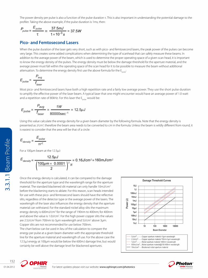
152
01.04.2012 For latest updates please visit our website: www.ophiropt.com/photonics
Beam
Pro
file
3.3.
1.1
The power density per pulse is also a function of the pulse duration τ. This is also important in understanding the potential damage to the profiler. Taking the above example, if the pulse duration is 1ms, then:
≡Ppulse =Epulse 37.5mJ
1 10-3 sτ= 37.5W
×
Pico- and Femtosecond LasersWhen the pulse duration of the laser gets very short, such as with pico- and femtosecond lasers, the peak power of the pulses can become very large. This creates some added complications when determining the type of scanhead that can safely measure these beams. In addition to the average power of the beam, which is used to determine the proper operating space of a given scan head, it is important to know the energy density of the pulses. The energy density must be below the damage threshold for the aperture material, and the average power must fall within the operating space of the scan head for it to be possible to measure the beam without additional attenuation. To determine the energy density first use the above formula for the E
pulse:
Most pico- and femtosecond lasers have both a high repetition rate and a fairly low average power. They use the short pulse duration to amplify the effective power of the laser beam. A typical laser that one might encounter would have an average power of 1.0 watt and a repetition rate of 80kHz. For this laser the E
pulse would be:
Using this value calculate the energy density for a given beam diameter by the following formula. Note that the energy density is presented as J/cm2; therefore the beam area needs to be converted to cm in the formula. Unless the beam is wildly different from round, it is easiest to consider that the area will be that of a circle:
EdensityEpulse=
r2 �
For a 100µm beam at the 12.5µJ:
Once the energy density is calculated, it can be compared to the damage threshold for the aperture type and the wavelength range for the aperture material. The standard blackened slit material can only handle 10mJ/cm2 before the blackening starts to ablate. For this reason, scan heads intended for use with these pico- and femtosecond lasers should have the reflective slits, regardless of the detector type or the average power of the lasers. The wavelength of the laser also influences the energy density that the aperture material can withstand. For the standard nickel alloy slits the maximum energy density is 600mJ/cm2 for the range of 190nm to 400nm; for 400nm and above the value is 1.0J/cm2. For the high power copper slits the values are 2.5J/cm2 from 700nm to 3μm wavelength and 5J/cm2 above 3µm. Copper slits are not recommended for use below 700nm. The chart below can be used in lieu of the calculation to compare the energy per pulse at a given beam diameter with the appropriate threshold line for the aperture material and wavelength of use. For the above case the 12.5µJ energy at 100µm would be below the 600mJ damage line, but would certainly be well above the damage level for blackened apertures.
Epulse =Pavg
laserf
Epulse =Pavg
laserf1W
80000sec -112.5µJ = =
Edensity =2�
12.5µJ
(100µm × 0.00012 )
= 0.16J/cm2 =160mJ/cm2

01.04.2012
153
For latest updates please visit our website: www.ophiropt.com/photonics
Beam
Pro
file
3.3.
1.1
Minimum Beam Size per Pulse Frequency
NanoScan Normal Drum Large Drum (HP)
Rotation Rate (Hz) 1.25 2.50 5.00 10.00 20 1.25 2.50 5.00 10.00
Slit Speed (µm/msec) 116.63 233.25 466.50 933.01 1866.01 233.25 466.50 933.01 1866.01
Data Points per Profile 15 15 15 15 15 15 15 15 15
Pulse Frequency (kHz) Minimum Beam Diameter in μm Minimum Beam Diameter in μm
0.5 3499 6998 N/A N/A N/A 6998 13995 N/A N/A
1 1749 3499 6998 N/A N/A 3499 6998 13995 N/A
2 875 1749 3499 6998 N/A 1749 3499 6998 13995
3 583 1166 2333 4665 N/A 1166 2333 4665 9330
4 437 875 1749 3499 6998 875 1749 3499 6998
5 350 700 1400 2799 5598 700 1400 2799 5598
6 292 583 1166 2333 4665 583 1166 2333 4665
7 250 500 1000 1999 3999 500 1000 1999 3999
8 219 437 875 1749 3499 437 875 1749 3499
9 194 389 778 1555 3110 389 778 1555 3110
10 175 350 700 1400 2799 350 700 1400 2799
11 159 318 636 1272 2545 318 636 1272 2545
12 146 292 583 1166 2333 292 583 1166 2333
13 135 269 538 1077 2153 269 538 1077 2153
14 125 250 500 1000 1999 250 500 1000 1999
15 117 233 467 933 1866 233 467 933 1866
16 109 219 437 875 1749 219 437 875 1749
17 103 206 412 823 1646 206 412 823 1646
18 97 194 389 778 1555 194 389 778 1555
19 92 184 368 737 1473 184 368 737 1473
20 87 175 350 700 1400 175 350 700 1400
21 83 167 333 666 1333 167 333 666 1333
22 80 159 318 636 1272 159 318 636 1272
23 76 152 304 608 1217 152 304 608 1217
24 73 146 292 583 1166 146 292 583 1166
25 70 140 280 560 1120 140 280 560 1120
50 35 70 140 280 560 70 140 280 560
100 17 35 70 140 280 35 70 140 280
150 12 23 47 93 187 23 47 93 187

154
01.04.2012 For latest updates please visit our website: www.ophiropt.com/photonics
Beam
Pro
file
3.3.
1.1
CollimationA single beam size measurement using a Collimation Fixture is all that is required to determine laser beam collimation, greatly simplifying this measurement. Real-time optical alignment can then be performed to determine best collimation. No special training is needed to perform these simple measurements. Unlike with most measurement shortcuts, high-precision collimation measurements can be performed with exceedingly high resolution, higher than alternative techniques. All that is required for these accurate measurements of collimation is a test lens and a NanoScan. The laser beam profiler is positioned such that it measures beam size at the geometric focus of the lens. From lens theory, the angle of collimation is determined by the equation: q = Df / f, where q is the angle of collimation, Df is the beam size measured at the focal length, and f is the focal length of the lens. Once the beam size is measured at the focal length of the lens, simply dividing this measured beam size by the divergence angle determines the laser beam collimation angle. The beam profiler remains fixed, and active alignment is easily performed in real time. This level of simplicity, speed, and functionality is simply not possible with techniques involving multiple beam profile positions.
Rayleigh Range Translation Test Fixture for NanoScan Photon Inc.’s Rayleigh Range Translation Test Fixture (RAL-FXT) provides convenient translation of a NanoScan scanhead assembly and a digital readout of its relative position along the beam axis. Used with a user-provided focusing lens and the M2 Wizard in the NanoScan Analysis Software, this fixture offers a quick and easy method to determine the times-diffraction propagation factor (M2 ) of a laser.
The RAL-FXT features a base plate, sliding carriage and digital micrometer. The base plate (5.4×10.2×0.38in.) provides a series of ¼-20 threaded mounting holes at 2in. centers to facilitate convenient fixturing of the assembly with respect to the focusing lens. The sliding carriage accommodates the combination of the 0.125-in. dowel pin and the ¼-20 mounting hole found on any Photon scan head’s rotation mount, and enables smooth movement of the scan head assembly over a 6-in. range of travel. A Mitutoyo micrometer with a handy re-zeroing feature and accompanying slide provides precise determination of the scan head location and/or travel distance with a resolution of tens of microns.
COL-FXT 250 Nominal 250mm focal length lens. Includes an enclosure to block stray light
COL-FXT 250 TEL Nominal 250mm focal length lens. For wavelengths of use at 1310 or 1550nm with lens repositioning. Includes an enclosure to block stray light
COL-FXT 500 MIR For wavelengths of use at 3–5µm.
COL-FXT C02 Zinc selenide (ZnSe) lens with a focal length of 190.5mm. For wavelength of use at 10.6m. Includes an enclosure that holds an adjustable entrance iris. Requires a Pyro NanoScan System.
Collimation Fixtures
Divergence/Collimation test fixtures based on a high quality test lens to focus your collimated or diverging beam.Fixtures require a complete NanoScan System.

01.04.2012
155
For latest updates please visit our website: www.ophiropt.com/photonics
Beam
Pro
file
3.3.
1.1
Item Description P/N
USB NS-Si/9/3.8 NanoScan Si Detector 9mm aperture <5micron slits. High-resolution head featuring Si detector, 63.5mm diameter head with rotation mount, 9mm entrance aperture, and matched pair of specially selected <5.0micron wide slits.Use from 190nm to wavelengths <1micron. Not for 1.06micron wavelength. USB
PH00249
USB NS-Si/3.5/1.8 NanoScan Silicon Detector 3.5mm aperture 1.8micron slits. High-resolution head featuring Silicon detector, 63.5mm diameter head with rotation mount, 3.5mm entrance aperture, and matched pair of 1.8micron wide slits. Use from 190nm to wavelengths <1micron. Not for 1.06micron wavelength. USB
PH00015
USB NS-Si/3.5/1.0 NanoScan Silicon Detector 3.5mm aperture 1.0micron slits. High-resolution head featuring Si detector, 63.5mm diameter head with rotation mount, 3.5mm entrance aperture, and matched pair of 1.0micron wide slits. Use from 190nm to wavelengths <1micron Not for 1.06micron wavelength. USB
PH00016
USB NS-Si/9/25 NanoScan Si Detector 9mm aperture 25micron slits. High-resolution head featuring Si detector, 63.5mm diameter head with rotation mount, 9mm entrance aperture, and matched pair of 25.0micron wide slits. Use from 190nm to wavelengths <1micron. Not for 1.06micron wavelength. USB
PH00017
USB NS-Si/9/5 NanoScan Si Detector 9mm aperture 5micron slits. High-resolution head featuring Si detector, 63.5mm diameter head with rotation mount, 9mm entrance aperture, and matched pair of 5.0micron wide slits. Use from 190nm to wavelengths <1micron. Not for 1.06micron wavelength. USB
PH00018
USB NS-Si/25/25 NanoScan Si Detector 25mm aperture 25micron slits. High-resolution head featuring Si detector, 100mm diameter head with rotation mount, 25mm entrance aperture, and matched pair of 25.0micron wide slits. Use from 190nm to wavelengths <1micron. Not for 1.06micron wavelength. USB
PH00019
USB NS-Ge/3.5/1.8 NanoScan Ge Detector 3.5mm aperture 1.8micron slits. High-resolution head featuring Germanium detector, 63.5mm diameter head with rotation mount, 3.5mm entrance aperture, and matched pair of 1.8micron wide slits. Use from 700nm to 1.8micron wavelength. USB
PH00020
USB NS-Ge/3.5/1.0 NanoScan Ge Detector 3.5mm Aperture 1.0micron slits. High-resolution head featuring Germanium detector, 63.5mm diameter head with rotation mount, 3.5mm entrance aperture, and matched pair of 1.0micron wide slits. Use from 700nm to 1.8micron wavelength. USB
PH00021
USB NS-Ge/9/25 NanoScan Ge Detector 9mm Aperture 25micron slits. High-resolution head featuring Germanium detector, 63.5mm diameter head with rotation mount, 9mm entrance aperture, and matched pair of 25micron wide slits. Use from 700nm to 1.8micron wavelength. USB
PH00022
USB NS-Ge/9/5 NanoScan Ge Detector 9mm Aperture 5.0micron slits. High-resolution head featuring Germanium detector, 63.5mm diameter head with rotation mount, 9mm entrance aperture, and matched pair of 5.0micron wide slits. Use from 700nm to 1.8micron wavelength. USB
PH00023
USB NS-Ge/12/25 NanoScan Ge Detector 12.5mm Aperture 25micron slits. High-resolution head featuring Germanium detector, 100mm diameter head with rotation mount, 12.5mm entrance aperture, and matched pair of 25micron wide slits. USB
PH00024
NS-USB NanoScan USB Controller /NS USB PH00030
NH NS-Si/3.5/1.8 Head only NanoScan-Si 3.5mm aperture 1.8µm slits PH00031
NH NS-Si/3.5/1.0 Head only NanoScan-Si 3.5mm aperture 1.0µm slits PH00032
NH NS-Si/9/25 Head only NanoScan-Si 9mm aperture 25µm slits PH00033
NH NS-Si/9/5 Head only NanoScan-Si 9mm aperture 5µm slits PH00034
NH NS-Si/25/25 Head only NanoScan-Si 25mm aperture 25µm slits PH00035
NH NS-Ge/3.5/1.8 Head only NanoScan-Ge 3.5mm aperture 1.8µm slits PH00036
NH NS-Ge/3.5/1.0 Head only NanoScan-Ge 3.5mm aperture 1.0µm slits PH00037
NH NS-Ge/9/25 Head only NanoScan-Ge 9mm aperture 25µm slits PH00038
NH NS-Ge/9/5 Head only NanoScan-Ge 9mm aperture 5µm slits PH00039
NH NS-Ge/12/25 Head only NanoScan-Ge 12mm aperture 25µm slits PH00040
P200 PH00046
Ordering Information - NanoScan Systems
All NanoScan Systems Include: NanoScan Integrated Software package. Beam Analysis Software for use with NanoScan scanheads under Microsoft Windows operating systems.
Includes single and multiple beam analysis capability, and ActiveX automation.
Measurements include: Spot size, position and position difference information.
Includes a targeting screen for position adjustment with 1/e² contours plotted.
Certificate of Calibration. Beam width is traceable to National Institute of Standards and Technology (NIST) to better than ±2% (NanoScan Pyroelectric detectors calibration to better than ±3%).
Accumulated Pointing Window

156
01.04.2012 For latest updates please visit our website: www.ophiropt.com/photonics
Beam
Pro
file
3.3.
1.1
NanoScan Options and AccessoriesItem Description P/N
NSEC Side exit cable option for NanoScan PH00252
Cable-x Custom NanoScan cable-length x PH00049
NS-YE Extension NanoScan cable 3m PH00050
C-Mnt C-Mount attachment for NS PH00051
NS Upgrade NS Software upgrade PH00054
COL-FXT 250 250 mm FL collimation fixture PH00070
COL-FXT 250 TEL-X 250 mm FL collimation fixture 1550nm PH00071
COL-FXT CO2
Collimation Fixture for 10.6µmWL PH00072
RAL-FXT Rayleigh fixture for manual M2 PH00073
RSP100 RailScan motion stage 100mm length PH00078
RSP200 RailScan motion stage 200mm length PH00079
RSP500 RailScan motion stage 500mm length PH00080
H-I LA Modify H-I for Large (100mm) Scan head PH00082
H-I 980-VIS w/lens NS lens mount bracket and 60X lens 980 WL PH00146
H-I 1550 w/ lens NS lens mount bracket and 40X lens 1550 WL PH00081
H-I High energy IR NS lens mount bracket w/ high energy lens WLxxx PH00147
H-I 100X NS lens mount bracket and 100X lens WLxxx PH00148
3180 Desktop PC computer operating MS windows loaded with appropriate Photon software PH00087
Power attenuation optionsItem P/N
HP-ND1 350 thru 399nm Must be ordered w/new system – Si & Ge only PH00370
HP-ND1 400 thru 700nm Must be ordered w/new system – Si & Ge only PH00371
HP-ND2 400 thru 700nm Must be ordered w/new system – Si & Ge only PH00372
HP-ND3 400 thru 700nm Must be ordered w/new system – Si & Ge only PH00373
HP-ND1 750 thru 890nm Must be ordered w/new system – Si & Ge only PH00374
HP-ND2 750 thru 890nm Must be ordered w/new system – Si & Ge only PH00375
HP-ND3 750 thru 890nm Must be ordered w/new system – Si & Ge only PH00376
HP-ND1 900 thru 1100nm Must be ordered w/new system – Si & Ge only PH00377
HP-ND2 900 thru 1100nm Must be ordered w/new system – Si & Ge only PH00378
HP-ND3 900 thru 1100nm Must be ordered w/new system – Si & Ge only PH00379
HP-ND1 1150 thru 1600nm Must be ordered w/new system – Si & Ge only PH00380
HP-ND2 1150 thru 1600nm Must be ordered w/new system – Si & Ge only PH00381
HP-ND3 1150 thru 1600nm Must be ordered w/new system – Si & Ge only PH00382
NanoScan Option NSEC: Side exit cable

01.04.2012
157
For latest updates please visit our website: www.ophiropt.com/photonics
Beam
Pro
file
3.3.
2
3.3.2 NanoScan for High-Power Beam ApplicationsPhoton’s High-Power NanoScan can measure focused CO
2 laser beams up to 5 kilowatts. The High-Power NanoScan is equipped with a
pyroelectric detector with copper slits and drum. A cooling fan mounted on the scan head body provides additional heat management. With the new “peak connect” algorithm and the software controlled variable scan speed, the High-Power NanoScan is ideal for measuring lasers operating with pulse width modulation (PWM) power control. Measurement of Q-switched lasers and other higher frequency pulsed lasers is also possible using this feature.
What Can be Measured?Measuring high-power beams can be tricky. The lasers have the potential to damage the scan head, and any reflected light can be dangerous to both the operator and the surroundings. The High-Power NanoScan can measure these beams because it uses a combination of highly reflective components with high thermal dissipation capability. It is important to manage the reflected beam so that it neither reenters the laser cavity nor sends stray beams into the surrounding area. The scan head is designed to make short duration measurements to avoid excessive heating of components. The head should be only in the incident beam for 10 to 60 seconds depending on the power levels to prevent excessive heating of the components. The High-Power NanoScan scan head has been shown to be able to handle power densities of 3.2MWcm-2 at 10.6µm, the power density of a 200µm beam at 1kW. At the shorter wavelengths of the other common industrial lasers, Nd:YAG and DPSS, the upper limits are a little less, due to the slightly lower reflectivity of the components at wavelengths around 1000nm. Visible and UV lasers can also be measured, but these will have lower limits yet.
The chart below shows the damage thresholds for pulsed beam energies for the three wavelength regimes. The lines represent the maximum energies per pulse for various spot sizes that correspond to 5J/cm2 for the 3µm to 100µm wavelengths, 2.5J/cm2 for the 700nm to 3µm range, and 250mJ/cm2 for the UV-Visible range from 190nm to 700nm. When operating with pulsed lasers, calculate the energy per pulse to ensure that the values fall below these lines for the wavelength of the laser. Operation above these values will likely cause damage to the scan head apertures.
High-Power NanoScan with cooling fan
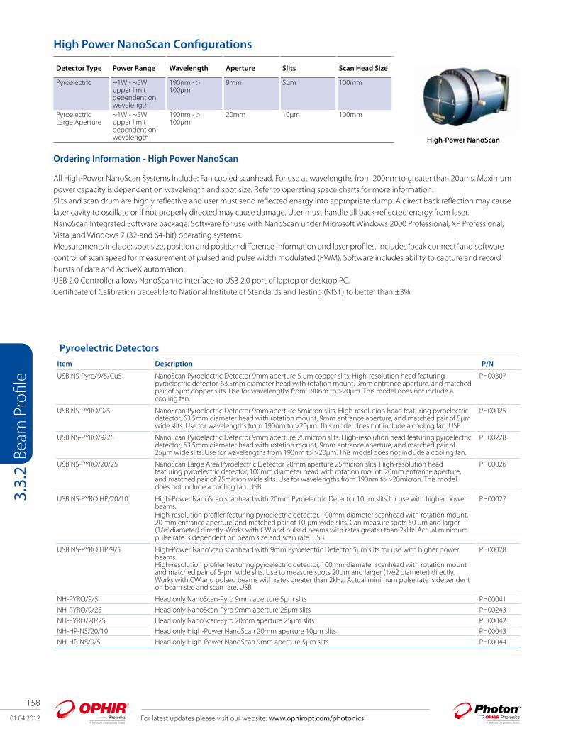
158
01.04.2012 For latest updates please visit our website: www.ophiropt.com/photonics
Beam
Pro
file
3.3.
2
Pyroelectric Detectors
Item Description P/N
USB NS-Pyro/9/5/Cu5 NanoScan Pyroelectric Detector 9mm aperture 5 μm copper slits. High-resolution head featuring pyroelectric detector, 63.5mm diameter head with rotation mount, 9mm entrance aperture, and matched pair of 5μm copper slits. Use for wavelengths from 190nm to >20μm. This model does not include a cooling fan.
PH00307
USB NS-PYRO/9/5 NanoScan Pyroelectric Detector 9mm aperture 5micron slits. High-resolution head featuring pyroelectric detector, 63.5mm diameter head with rotation mount, 9mm entrance aperture, and matched pair of 5µm wide slits. Use for wavelengths from 190nm to >20µm. This model does not include a cooling fan. USB
PH00025
USB NS-PYRO/9/25 NanoScan Pyroelectric Detector 9mm aperture 25micron slits. High-resolution head featuring pyroelectric detector, 63.5mm diameter head with rotation mount, 9mm entrance aperture, and matched pair of 25μm wide slits. Use for wavelengths from 190nm to >20μm. This model does not include a cooling fan.
PH00228
USB NS-PYRO/20/25 NanoScan Large Area Pyroelectric Detector 20mm aperture 25micron slits. High-resolution head featuring pyroelectric detector, 100mm diameter head with rotation mount, 20mm entrance aperture, and matched pair of 25micron wide slits. Use for wavelengths from 190nm to >20micron. This model does not include a cooling fan. USB
PH00026
USB NS-PYRO HP/20/10 High-Power NanoScan scanhead with 20mm Pyroelectric Detector 10μm slits for use with higher power beams.High-resolution profiler featuring pyroelectric detector, 100mm diameter scanhead with rotation mount, 20 mm entrance aperture, and matched pair of 10-μm wide slits. Can measure spots 50 μm and larger (1/e2 diameter) directly. Works with CW and pulsed beams with rates greater than 2kHz. Actual minimum pulse rate is dependent on beam size and scan rate. USB
PH00027
USB NS-PYRO HP/9/5 High-Power NanoScan scanhead with 9mm Pyroelectric Detector 5μm slits for use with higher power beams.High-resolution profiler featuring pyroelectric detector, 100mm diameter scanhead with rotation mount and matched pair of 5-μm wide slits. Use to measure spots 20μm and larger (1/e2 diameter) directly. Works with CW and pulsed beams with rates greater than 2kHz. Actual minimum pulse rate is dependent on beam size and scan rate. USB
PH00028
NH-PYRO/9/5 Head only NanoScan-Pyro 9mm aperture 5µm slits PH00041
NH-PYRO/9/25 Head only NanoScan-Pyro 9mm aperture 25μm slits PH00243
NH-PYRO/20/25 Head only NanoScan-Pyro 20mm aperture 25µm slits PH00042
NH-HP-NS/20/10 Head only High-Power NanoScan 20mm aperture 10µm slits PH00043
NH-HP-NS/9/5 Head only High-Power NanoScan 9mm aperture 5µm slits PH00044
Ordering Information - High Power NanoScan
All High-Power NanoScan Systems Include: Fan cooled scanhead. For use at wavelengths from 200nm to greater than 20μms. Maximum power capacity is dependent on wavelength and spot size. Refer to operating space charts for more information. Slits and scan drum are highly reflective and user must send reflected energy into appropriate dump. A direct back reflection may cause laser cavity to oscillate or if not properly directed may cause damage. User must handle all back-reflected energy from laser.NanoScan Integrated Software package. Software for use with NanoScan under Microsoft Windows 2000 Professional, XP Professional, Vista ,and Windows 7 (32-and 64-bit) operating systems.Measurements include: spot size, position and position difference information and laser profiles. Includes “peak connect” and software control of scan speed for measurement of pulsed and pulse width modulated (PWM). Software includes ability to capture and record bursts of data and ActiveX automation.USB 2.0 Controller allows NanoScan to interface to USB 2.0 port of laptop or desktop PC. Certificate of Calibration traceable to National Institute of Standards and Testing (NIST) to better than ±3%.
Detector Type Power Range Wavelength Aperture Slits Scan Head Size
Pyroelectric ~1W - ~5W upper limit dependent on wevelength
190nm - > 100μm
9mm 5μm 100mm
Pyroelectric Large Aperture
~1W - ~5W upper limit dependent on wevelength
190nm - > 100μm
20mm 10μm 100mm
High-Power NanoScan
High Power NanoScan Configurations

01.04.2012
159
For latest updates please visit our website: www.ophiropt.com/photonics
Beam
Pro
file
3.4.
1
3.4 Accessories for Beam Profiling
IntroductionSpiricon has the most extensive array of accessories for beam profiling existing. There are components for attenuating, filtering, beam splitting, magnifying, reducing and wavelength conversion. There are components for wavelengths from the deep UV to CO2 wavelengths. Most of the components are modular so they can be mixed and matched with each other to solve almost any beam profiling requirement needed.
3.4.1 Neutral Density Attenuators/Filters For almost all applications, the laser beam intensity is too high for the operating range of the CCD. Therefore ND glass attenuator filters are available to reduce the intensity to the proper level at the CCD. In general, either the LBF-50 attenuating filer set or a set of individual, stackable, screw on filters is recommended. These filters are carefully designed not to affect beam quality or cause interference effects. One stackable ND1 filter and 2 ND2 filters are supplied standard with each camera.
Stackable ND filtersThe individual filters come in three versions, the ND1 filter in the red housing with ~10% transmission in the visible, the ND2 filter in the black housing with ~1% transmission and the ND3 filter in the green housing with ~0.1% transmission. The individual filters can be screwed on top of each other and thus stacked. They are set at a small wedge angle in the housing so as not to cause interference effects.
LBF-50The LBF-50 comes with a set of filters that are inserted into the flange shown, mounted on top of each other and secured. A set of 6 filters is provided that can achieve attenuation anywhere from ND 0.3 to ND 8. The LBF-50 is especially useful for CS or C mount cameras with the CCD recessed way below the surface. The filters are recessed into the camera thus saving thickness as shown in the illustration to the right.
LBF - 50 filter assembly
Stackable filtershowing wedge
LBF-50 on C mount camera
ND1, ND2 and ND3 stackable filters
Model StackableND FiltersND1/ND2/ND3
LBF-50
ContinuouslyVariable
ATP-K Variable Attenuator
UV ND Filters Speciality Filterfor 355nm
Speciality Filterfor 1300nm
Nominal ND value 1,2,3
0.3, 0.7, 1, 2, 3, 4 1-6 continuouslyvariable
ND=1.7-4.6Max. ND: 7.4 (with fixed 2.8 gray-glass attenuator)
0.3, 0.7, 1.0, 1.3, 1.7, 2.0, 2.3, 2.7, 3.0, 3.3, 3.7, 4.0, 4.3, 4.7, 5.0, 6.0
Pass 355nm, blocks 532nm & 1064nm
Pass 1300nm,blocks <1100nm
Clear aperature Ø19mm Ø12mm Ø20mm Ø15mm Ø20mm Ø19mm Ø19mmDamage threshold
5W/cm2
no distortion5W/cm2
no distortion5W/cm2
no distortion100mW/mmno thermal lensing
100W/cm2 CW, 10ns pulses, no distortion
5W/cm2
no distortion5W/cm2
no distortion
Mounting C-Mount Threads C-Mount Threads C-Mount Threads C-Mount Threads C-Mount Threads C-Mount Threads C-Mount Threads
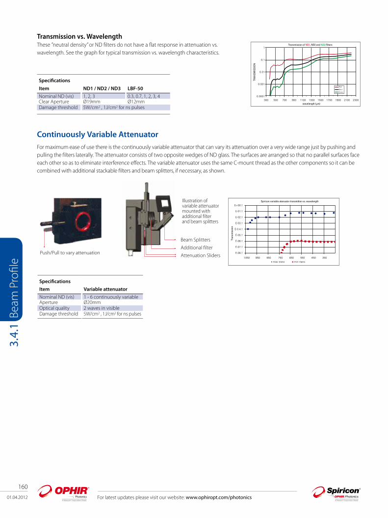
160
01.04.2012 For latest updates please visit our website: www.ophiropt.com/photonics
Beam
Pro
file
3.4.
1
Transmission vs. Wavelength These ”neutral density” or ND filters do not have a flat response in attenuation vs. wavelength. See the graph for typical transmission vs. wavelength characteristics.
Specifications
Item ND1 / ND2 / ND3 LBF-50
Nominal ND (vis) 1, 2, 3 0.3, 0.7, 1, 2, 3, 4Clear Aperture Ø19mm Ø12mmDamage threshold 5W/cm2 , 1J/cm2 for ns pulses
Continuously Variable AttenuatorFor maximum ease of use there is the continuously variable attenuator that can vary its attenuation over a very wide range just by pushing and pulling the filters laterally. The attenuator consists of two opposite wedges of ND glass. The surfaces are arranged so that no parallel surfaces face each other so as to eliminate interference effects. The variable attenuator uses the same C-mount thread as the other components so it can be combined with additional stackable filters and beam splitters, if necessary, as shown.
Push/Pull to vary attenuation
Illustration of variable attenuator mounted with additional filter and beam splitters
Additional filter
Beam Splitters
Attenuation Sliders
Specifications
Item Variable attenuator
Nominal ND (vis) 1 - 6 continuously variableAperture Ø20mmOptical quality 2 waves in visibleDamage threshold 5W/cm2 , 1J/cm2 for ns pulses

01.04.2012
161
For latest updates please visit our website: www.ophiropt.com/photonics
Beam
Pro
file
3.4.
1
ATP-K Specifications
Maximum Power/Energy Handling 100 mW/mm beam diameter 100 mJ total avg. energy Damage threshold: 5J
Note: Powerful laser sources may require additional attenuation prior to the beam’s exposure to Model ATP-K. Additional attenuation usually is achieved by use of high-power laser mirror attenuators or clean, high-quality quartz plates (recommended with slight wedge angles).
Wavelength Range 360-2500+ nm Near flat response out to 1500nm
Attenuation Range Variable filters: ND = 1.7 to 4.6 Maximum ND 7.4 (with fixed 2.8 gray-glass attenuator)
Note: ND (optical density) = log (1/T) or T=10 (-ND) where T is the fraction of light transmitted. For example, an ND of 5 transmits 0.00001 or 0.001%.
Clear Aperture 15mm diameter
Dimensions 94 (W) x 28 (H) x 43 (D) mm
Thickness Tolerance ±0.25mm
Mounting C-mount
Base Mount ¼-20
Figure 2 – Point at which damage will occur with pulsed energy
Figure 1 – Safe average power for negligible beam distortion
ATP-K Variable AttenuatorThis option makes beam profiling easy. The ATP-K attenuates your laser without ghost reflections or fringes and has a knob-operated variable wedge attenuator of ND 1.7–4.6, and comes with a fixed gray-glass attenuator with ND 2.8. The ATP-K is also designed to be used with the HP-XXX high power attenuators and beam splitters. Both types of attenuators attach directly to the ATP-K via C-mount. The ATP-K has simple reproducible attenuation settings, and has a wavelength range of 360 to 2500+ nm.
Figure 1 below shows the safe average power for negligible beam distortion from thermal lensing. Absorptive filters, such as used in the ATP-K have an upper power limit of approximately 100mW per mm beam diameter. For pulsed beams, Figure 2 shows the damage threshold for energy where breakage of the glass wedge may occur. This is approximately 5J per mm beam diameter. For lasers with power or energy levels above this the first stage of attenuation will need to come from our line of high power reflective attenuators.
High Power Attenuators
Our high-power laser mirror attenuator transmits <1%, and comes in a C-Mount threaded adapter ring. It is also AR coated for either straight on or 45° orientation.
Available standard configurations:
HP-266 — Use for 266 ±50nm
HP-355 — Use for 350 ±50nm
HP-450 — Use for 450 ±50nm
HP-600 — Use for 500–700nm
HP-800 — Use for 700–900nm
HP-1064 — Use for 1000–1100nm
Other wavelengths available upon request.Note that if more than one reflective attenuator is required to reduce the beam power, one of them must be oriented 45° to the beam. Unlike absorptive attenuators, reflectors cannot be stacked, because they will form a laser cavity.

162
01.04.2012 For latest updates please visit our website: www.ophiropt.com/photonics
Beam
Pro
file
3.4.
1
UV ND FiltersThis accessory can be used with any camera fitted with C- mount threads. Simply thread the attenuator assembly into the front of the camera and then slide the ND filter arrays to get the desired amount of attenuation. This device can be used with laser outputs from microwatts to Watts. Three filter holders are provided with two filters in each holder. Each filter in the holder provides for a different value of attenuation. To use, slide the desired holder into the housing slot. A click is felt when the filter is properly aligned with the beam. The holders provided will allow for at-tenuation of up to ND 6. C-mount interface for universal application to our CCD and Pyroelectric cameras 190-380nm attenuation covers Excimer, Helium Cadmium, and the Nd:YAG UV harmonic laser wavelengths.Attenuation with these ND filters permits the best use of the dynamic range of a beam profil-ing camera.Attenuation range of 0.3 to 6.0 optical densities (ND).Set consists of three slides with two filters in each slide.The Six Filters include 0.3, 0.7, 1.0, 2.0, 3.0 and 4.0 optical densities.Two filters can be employed at one time for 0.3 – 6.0 optical attenuation in 0.3 or 0.4 ND steps.20mm clear aperture will not vignette any of our applicable camera sensors.Damage threshold = 100W/cm2 for CW lasers and 20mJ/cm2 for nano-second pulse width lasers.Additional Beam Splitters can be added for attenuation of high power UV lasers.UV attenuation system uses high quality optics from the leader in laser beam diagnostics.
Specialized Filters There are also specialized filters available to eliminate extraneous wavelengths when measuring very short or very long wavelengths where the CCD cameras are not sensitive and the desired signal can get swamped by extraneous light of other wavelengths. These filters are as follows:
1. The 355nm filter for monitoring the 3rd harmonic of YAG. This filter transmits 355nm but blocks 532nm and 1064nm.
2. The 1300nm filter transmits1300nm but blocks wavelengths shorter than 1100nm.
These filters are also on the same standard thread so they can be mixed with all the other components. See ordering information pages for more details.
Specifications
Item UV ND Filters
Nominal ND (UV) 0.3, 0.7, 1.0, 1.3 ,1.7, 2.0, 2.3, 2.7, 3.0, 3.3, 3.7, 4.0, 4.3, 4.7, 5.0, 6.0
Aperture Ø20mmDamage threshold 100W/cm2 CW, 10ns pulses, no
distortion

For latest updates please visit our website: www.ophiropt.com/photonics 01.04.2012
163
Beam
Pro
file
3.4.
2Model LBS-300 LBS-100
Wavelength multiple versions from 190 to 1550nm multiple versions; 400-900nm, 1064nm, 10.6µmReflection 0.01% of incident beam 4% @ 400-900nm, 1% @1064nm, 0.5% or 5% @10.6µmNominal ND value (vis) 0.3, 0.7, 1, 2, 3, 4 0.3, 0.7, 1, 2, 3, 4 for 300-900nm & 1064nm 30%
& 60% for 10.6µmClear aperature Ø17.5mm Ø19mmDamage threshold see spec sheet 5W/cm2 no distortionMounting C-Mount Threads Lab post mounted
3.4.2 Beam Splitter + Neutral Density Filters Combo The attenuators described before can provide a high degree of attenuation however, these neutral density attenuators cannot dissipate more than 5W or so. Therefore we often place beam splitters in front of the attenuators to reduce the intensity before the ND filters. These beam splitters are made of UV grade fused silica for use from 190 to 2000nm. Since they do not absorb light, they have a much higher power handling capacity than the ND attenuator/filters.
Ordering Information Item Description P/N ND1 stackable filter (red housing)
4mm spacing screw on filter for camera with transmission of between 20% and 5% depending on spectral range.Can be stacked and combined with other filters and beam splitters.. One filter is included with Spiricon cameras.
SPZ08234
ND2 stackable filter (black housing)
4mm spacing screw on filter for camera with transmission of between 7% and 0.5% depending on spectral range. Can be stacked and combined with other filters and beam splitters. Two filters are included with Spiricon cameras.
SPZ08235
ND3 stackable filter (green housing)
4mm spacing screw on filter for camera with transmission of between 2% and 0.05% depending on spectral range. Can be stacked and combined with other filters and beam splitters.
SPZ08253
LBF-50 filter set Compact screw in filter holder with set of ND filters. Attenuations from low to 106. SP90081Filter holder and 50x50 filter set
Filter holder with set of 4 standard Schott 50X50mm neutral density filters. Useful to reduce intensity before inputting into 4X beam reducer. Mounts to standard ¼” thread, ½” diameter laboratory rod.
SPZ08240
Variable filter Continuously variable filter for complete control over beam intensity. Especially useful for pulsed lasers. Varies the intensity over more than 4 orders of magnitude between wavelengths 350nm and 1100nm. Can be stacked and combined with other filters and beam splitters.
SPZ17012
ATP-K Variable Attenuator Package provides smooth knob operated variable wedges with attenuation of optical density (ND) 1.7–4.6 for a total attenuation capability of ND 7.4. Specially designed to eliminate ghost reflections, fringes, and light leaks. Small compact module including C-mount adapter to attach to camera, and C-mount receptacle to easily attach additional HP-series attenuators.
PH00128
HP-266 High power laser grade fused silica reflective mirror attenuator for UV applications at 266nm. Second surface anti-reflection coated. Transmits <1%. Useful 266 ±50nm.
PH00129
HP-355 High power laser grade fused silica reflective mirror attenuator for UV applications at 355nm. Second surface anti-reflection coated. Transmits <1%. Useful 355 ±50nm.
PH00130
HP-450 High power laser mirror attenuator for applications in the visible from 400-500nm. Second surface anti-reflection coated.Transmits <1%. Useful 450 ±50nm.
PH00131
HP-600 High power laser mirror attenuator for applications in the visible from 500-700nm. Transmits <1%. PH00132
HP-800 High power laser mirror attenuator for applications in the visible-Near IR from 700-900nm. Transmits <1%. PH00133
HP-1064 High power laser mirror attenuator for applications in the Near IR from 1000-1100nm. Transmits <1%. PH00134
UV ND Filters 3 Filters holders each with 2 inconel UV ND.Filters for attunation up to ND 6.
SP90228
Filter for 355nm-V2; give an undistorted image of the 355nm light
Silicon cameras can see the 355nm 3rd harmonic radiation of YAG. The YAG however usually emits some light at 532nm and 1064nm as well. This filter filters out the other 2 wavelengths to give undistorted image of the 355nm light.
SPZ08246
Filter for 1300nm For all cameras that can operate at 1300nm but are quite insensitive there. This filter filters out all light below 1100nm to allow viewing 1300nm radiation without background interference.
SPZ08242

164
01.04.2012 For latest updates please visit our website: www.ophiropt.com/photonics
Beam
Pro
file
3.4.
2
LBS-300 Beam Splitters
The LBS-300 beam splitter attachment for C-mount, CS-mount, or Ophir mount cameras allow you to measure laser beams with diameters up to 15mm and powers ranging from 10 mWatts to ~400 Watts. The beam sampler is designed so that the preferential polarization selection effect of a single wedge is cancelled out and the resulting beam image is polarization corrected to restore the polarization components of the original beam. The beam sampler operates by reflecting the incoming beam from the front surfaces of a pair of wedges through 90 degrees into the camera. Approximately 99% of the beam is transmitted through the beam sampler with 0.01% passed on to the camera. A set of adjustable ND filters are provided to make final intensity adjustments to the beam before it reaches the camera imager. As an option, you may order the WVF-300 (P/N SP90195) continuously variable ND filter set that can slide in and replace the fixed ND filters. If additional attenuation is needed, an external wedge (P/N SPZ17015) may be mounted at the input port, however this 3rd wedge will cause polarization selectivity when the beam is significantly polarized different in the S and P planes. Alternatively, two LBS-300s can be coupled in series providing up to a 10-8 attenuation.
Primary beam out
Primary beam in
2 - 45° wedges to reflect the primary beam into the camera
Selection of 4 adjustable ND filters
Ordering InformationModel LBS-300-UV LBS-300-VIS LBS-300-NIR LBS-300-BBPart No. SP90183 SP90184 SP90185 SP90186Wavelength 266-355nm 400-700nm 1064nm 190-1550nmWedge Material UVFS BK7 BK7 UVFSWedge Coating A/R ≤1% AR ≤1% AR ≤1% No coating, 4% reflectionClear aperture 17.5mm 17.5mm 17.5mm 17.5mmReflection 0.01% 0.01% 0.01% 0.16%Wedge ND value, each ND ≥2 ND ≥2 ND ≥2 ND ~1.3ND Filters Inconel Bulk ND Bulk ND One each of the UV, VIS & NIR setsND Values, nominal 0.3, 0.7, 1.0, 2.0, 3.0, 4.0
(Blu holders)0.3, 0.7, 1.0, 2.0, 3.0, 4.0 (Grn holders)
0.3, 0.7, 1.0, 2.0, 3.0, 4.0 (Red holders)
See UV, VIS and NIR descriptions
Filter Slides 3 3 3 9Maximum allowable input to filter (1)
100 W/cm2 CW20mJ/cm2, 10ns pulse
50 W/cm2
1J/cm2, 10ns pulse50 W/cm2
1J/cm2, 10ns pulseSee adjacent specifications
AccessoriesWedge Variable ND Filter kit N/A WVF-300 SP90195 WVF-300 SP90195 WVF-300 SP90195Beam Dumps BD-040-A, 40 Watts Max Power, Air Cooled SP90192
BD-500-W, 500 Watts Max Power, Water Cooled SP90193Beam Deflector Assemby for 400-1100 nm only SP90263Large C-mount Wedge Splitter
For additional attenuation add this to the front end of the LBS-300. Good for 350-2000mm SP90273
Note: (1) ND bulk absorbing filters damage threshold is 50W/cm2 but should be used at <5W/cm2 to avoid thermal lensing effects.
Optional SP90273 Large C-mount Wedge Splitter

01.04.2012
165
For latest updates please visit our website: www.ophiropt.com/photonics
Beam
Pro
file
3.4.
2
LBS-100 Attenuator
The LBS-100 system that is not as compact as the LBS-300 above but has larger aperture, and has versions for longer wavelengths. The system contains the mounting frame, 1 wedge beam splitter and several attenuators. The exit end of the LBS-100 is standard C mount thread so all our cameras can be mounted to the frame. The wedge angle is 6.5 degrees to insure that the reflection from the rear side will not enter the camera. The optical elements are flat to 1/4 wave in the visible to insure no distortion of the beam.
The LBS beam splitter/attenuator system can be combined with the 4X beam reducer, as shown above, to attenuate and view large beams.
LBS-100 System
Camera 4X beamreducer
LBS-100 to 4X beam reducer adaptor
LBS-100Incoming Beam
Ordering InformationItem Wavelength
rangeAbsorber material
Neutral Densities or transmission
Wedge material and reflection
Max power density on ND filters
Clear aperture Dimensions P/N
LBS-100 400 - 900nm recommended, functional to 2600nm
Neutral density glass
0.3, 0.7, 1.0, 2.0, 3.0, 4.0 ND at 632nm
Fused Silica 4% in wavelength range 400 - 900nm
5W/cm2 for no distortion, 50W/cm2 damage
19mm 65mm W x 55mm H x 140mm D
SP90061
LBS-100 YAG 1064nm Same Same 1% at 1064nm Same Same Same SP90057LBS-100 IR 0.5 10.6µm CaF2 flats,3 -3mm
and 1-1mm30% T for 3mm flat, 60% T for 1mm flat at 10.6µm
ZnSe 0.5% at 10.6µm
Same Same Same SP90058
LBS-100 IR 5.0 10.6µm Same Same ZnSe 5% at 10.6µm
Same Same Same SP90059
LBS-100 to 4X beam reducer adapter
This adapter enables mounting of the LBS-100 beam splitter/attenuator assembly in front of the 4X beam reducer. The combined assembly can image large high power beams in one unit.
SPZ17029

166
01.04.2012 For latest updates please visit our website: www.ophiropt.com/photonics
Beam
Pro
file
3.4.
3
Beam Tap I & ll Dual surface reflector for equalizing S & P polarization The two planes of reflection are orthogonal
Single Surface Polarization Problems
A single surface reflection at 45° is often used to sample a laser beam for profile measurements or for monitoring power or energy. However, as shown, at 45° a single surface reflects the S polarization component at more than 10 times the reflection of the P component. Depending on the laser polarization content, or stability, this sampling can provide very misleading and unreliable measurements. (The BT-I-YAG has both surfaces A/R coated for 1064nm so the reflection for both polarizations is equal at 0.5%. At other wavelengths far from 1064nm the above discussion applies).
Equalizing S & P reflected polarization
Any arbitrary polarization component can be broken into equivalent S & P components. With complimentary sampling surfaces any given component gets reflected once as the S polarization, and the second time as the P polarization. Thus using 2 surfaces, the total reflected energy for all polarization components is the sum of the S reflectance and the P reflectance. This causes the sampled beam to have S & P components that are identical to the original beam.
Model Beam Tap l & ll Beam Tap l & ll YAG Stackable Beam Splitter
Wavelength 400-700nm 1064nm 190-2000nmReflection 4% & 0.16% of incident beam 0.5% & 0.0025% of incident beam 5% & 0.025% of incident beamClear aperature Ø17.5mm Ø17.5mm Ø15mmDamage threshold 5W/cm2 no distortion 5W/cm2 no distortion >5J/cm2
Mounting C-Mount Threads C-Mount Threads C-Mount Threads
3.4.3 Beam Splitter

01.04.2012
167
For latest updates please visit our website: www.ophiropt.com/photonics
Beam
Pro
file
3.4.
3
Beam path through beam tap
The Beam Tap II uses two reflecting surfaces such that the two planes of reflection are orthogonal. The standard Beam Tap I rear surface is AR coated from 400-700nm.
This diagram shows the 6mm offset of the through beam that is created by the reflecting optic. The deflection angle of the output beam is less than 0.007 degrees. The rear surface of the flat is AR coated to maximize the throughput of the main beam. The standard Beam Tap II rear surface is AR coated for 400nm-700nm. The YAG version is AR coated for 1064nm on both surfaces.
Beam tap relection vs wavelength
Shown is the Beam Tap II final sampled reflection vs. wavelength. As shown both the S & P reflection are nearly constant at 0.05% from the UV to the infrared.
Ordering InformationModel Surface Wavelength range Optical Material Reflection P/NBT-I Single surface, 1 cube 400-700nm UVFS 4% Ravg SP90135BT-II Dual surface, 2 cubes 400-700nm UVFS 0.16% Ravg SP90133BT-I-YAG Single surface, 1 cube 1064nm BK7 0.5% Ravg SP90173BT-II-YAG Dual surface, 2 cubes 1064nm BK7 0.0025% Ravg SP90172
6mm TypicalBeam Offset
Stackable Beam SplittersThe stackable beam splitters are designed for maximum modularity and shortest beam path. They are compatible with almost all of our cameras having the standard C mount thread and can mount either to other attenuators or to the camera itself. Each beam splitter reduces the intensity of the beam by ~20 times (see graph below) so if a camera is equipped with filters that can operate with lasers typically up to ~1 Watt, with one beam splitter it can operate up to ~20 Watts and with two beam splitters up to ~400W. The Beam Splitters will operate for wavelengths from 190nm to 2000nm. The damage threshold of the beam splitters is >5J/cm2 for 10ns pulses. The beam splitters are mounted over the fixed or variable attenuators with a simple fastening ring and can be oriented in any direction with the beam coming from right, left up, down ,or front.
The wedge angle of 10 degrees insures that only the reflection from the front surface will appear on the camera with no double images. The user must insure that there are beam stops for the transmitted and reflected beams.
Note that if possible, the user should use an even number of beam splitters so as to cancel any possible polarization effects.
(Wevelength (nm
Perc
ent r
eflec
tanc
e pe
r sur
face
One beam splitter mounted Two beam splitters mounted
beam path

168
01.04.2012
Beam Profile
3.4.
4
With large beam splitter mounted showing how toimage converging beam
Beam expanders are available for 4.5mm spacing CS mount 12.5mm spacing cameras. The 4X beam expander is an expanding telescope that images the beam as it looks at 8mm from the end of the expander onto the CCD while enlarging the image 4X. In addition to the 4X beam expander, other microscope objectives are available for expanding the beam even more. There are objectives for 6X, 12X and 22X expansion. The various expanders allow the use of our 2% and 10% filters as well as the variable attenuator so as to accommodate the camera to a wide range of source intensities .
With a camera having 4.4µm pixel spacing using the beam expander, the effective resolution can be as good as 0.5µm. The object plane that is imaged onto the CCD is located several mm in front of the assembly so even hard to get to focal spots and other small images are easy to image. The beam expanders are designed to accommodate up to 3 screw on filters or a variable attenuator behind them so a wide range of intensities can be accommodated.
For intensities too large to be accommodated by just filters, beam splitters are available to reduce the intensity before the beam expander. The beam expander is primarily intended for nonparallel beams such as focal spots and fiber tips. If small parallel beams are imaged, interference effects may occur.
The 4X Beam expander can also be fitted with a UV converter plate at its object plane so that you can look at small beams in the spectral range 193-360nm and expand them 4X. See ordering information for further details.
Microscope objective assembly with beam splitter mounted
Ordering InformationItem Description Aperture Path length to CCD with
3 screw-on ND filtersP/N
1st Wedge Beam Splitter
45 degree wedged beam splitter to reduce intensities on image converter by ~20X. Aperture is 15mm
15mm(1) 60mm SPZ17015
2nd Wedge Beam Splitter
Additional wedge beam splitter to mount to 1st wedge beam splitter
93mm SPZ17026
(1) For converging beams a larger aperture 1st beam splitter is available P/N SPZ 17025. In that case, the aperture at the 1st beam splitter is 30mm
Large aperture 1st Wedge Beam Splitter
For converging beams a larger aperture 1st wedge beam splitter. Aperture is 30mm
30mm SPZ17025
Model 4X Beam Expander with UV Converter
Beam Expander
Wavelength 193nm-360nm 400-1800nmBeam Size Change 4X Expansion 4X, 6X, 12X, 22XClear aperture 1/4 the size of the CCD
imager
Mounting C-Mount Threads
3.4.4 Beam Expanders Microscope Objectives
Camera with 4X Beam Expander
Screw on filters
Object plane 8mm in frontof device
For latest updates please visit our website: www.ophiropt.com/photonics
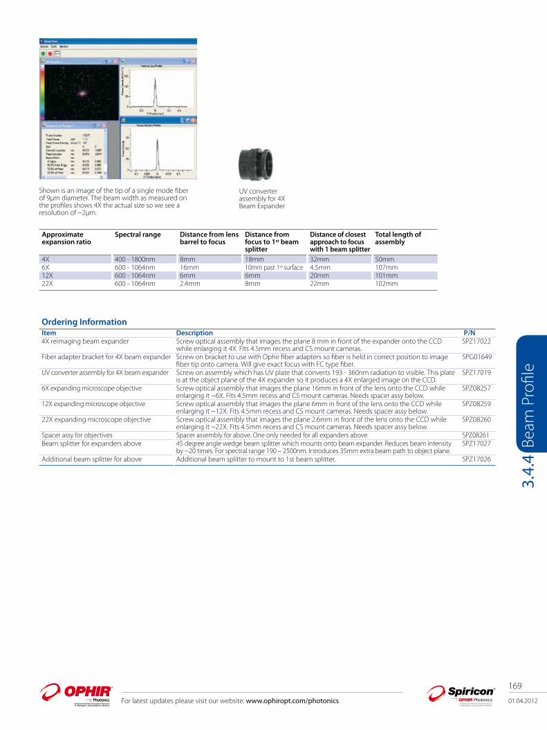
01.04.2012
169
For latest updates please visit our website: www.ophiropt.com/photonics
Beam
Pro
file
3.4.
4
Approximate expansion ratio
Spectral range Distance from lens barrel to focus
Distance from focus to 1st beam splitter
Distance of closest approach to focus with 1 beam splitter
Total length of assembly
4X 400 - 1800nm 8mm 18mm 32mm 50mm6X 600 - 1064nm 16mm 10mm past 1st surface 4.5mm 107mm12X 600 - 1064nm 6mm 6mm 20mm 101mm22X 600 - 1064nm 2.4mm 8mm 22mm 102mm
Shown is an image of the tip of a single mode fiber of 9µm diameter. The beam width as measured on the profiles shows 4X the actual size so we see a resolution of ~2µm.
UV converter assembly for 4X Beam Expander
Ordering InformationItem Description P/N 4X reimaging beam expander Screw optical assembly that images the plane 8 mm in front of the expander onto the CCD
while enlarging it 4X. Fits 4.5mm recess and CS mount cameras. SPZ17022
Fiber adapter bracket for 4X beam expander Screw on bracket to use with Ophir fiber adapters so fiber is held in correct position to image fiber tip onto camera. Will give exact focus with FC type fiber.
SPG01649
UV converter assembly for 4X beam expander Screw on assembly which has UV plate that converts 193 - 360nm radiation to visible. This plate is at the object plane of the 4X expander so it produces a 4X enlarged image on the CCD.
SPZ17019
6X expanding microscope objective Screw optical assembly that images the plane 16mm in front of the lens onto the CCD while enlarging it ~6X. Fits 4.5mm recess and CS mount cameras. Needs spacer assy below.
SPZ08257
12X expanding microscope objective Screw optical assembly that images the plane 6mm in front of the lens onto the CCD while enlarging it ~12X. Fits 4.5mm recess and CS mount cameras. Needs spacer assy below.
SPZ08259
22X expanding microscope objective Screw optical assembly that images the plane 2.6mm in front of the lens onto the CCD while enlarging it ~22X. Fits 4.5mm recess and CS mount cameras. Needs spacer assy below.
SPZ08260
Spacer assy for objectives Spacer assembly for above. One only needed for all expanders above. SPZ08261Beam splitter for expanders above 45 degree angle wedge beam splitter which mounts onto beam expander. Reduces beam intensity
by ~20 times. For spectral range 190 – 2500nm. Introduces 35mm extra beam path to object plane.SPZ17027
Additional beam splitter for above Additional beam splitter to mount to 1st beam splitter. SPZ17026
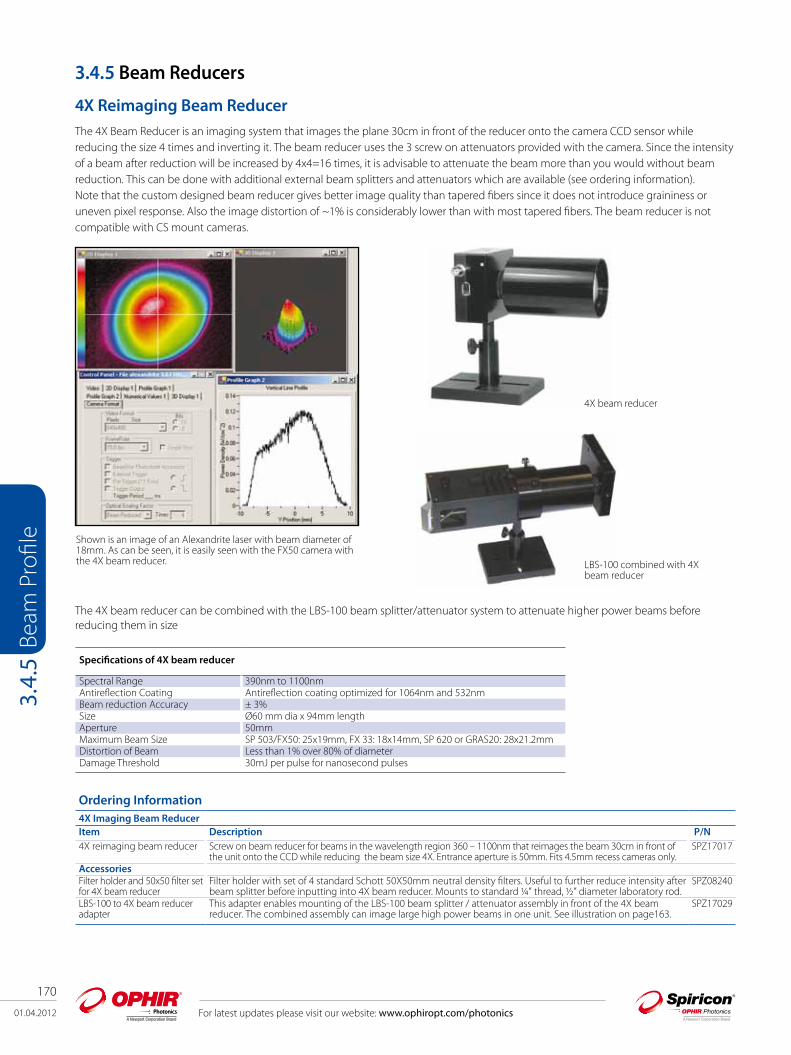
170
01.04.2012
Beam
Pro
file
3.4.
5
For latest updates please visit our website: www.ophiropt.com/photonics
3.4.5 Beam Reducers
4X Reimaging Beam Reducer The 4X Beam Reducer is an imaging system that images the plane 30cm in front of the reducer onto the camera CCD sensor while reducing the size 4 times and inverting it. The beam reducer uses the 3 screw on attenuators provided with the camera. Since the intensity of a beam after reduction will be increased by 4x4=16 times, it is advisable to attenuate the beam more than you would without beam reduction. This can be done with additional external beam splitters and attenuators which are available (see ordering information). Note that the custom designed beam reducer gives better image quality than tapered fibers since it does not introduce graininess or uneven pixel response. Also the image distortion of ~1% is considerably lower than with most tapered fibers. The beam reducer is not compatible with CS mount cameras.
The 4X beam reducer can be combined with the LBS-100 beam splitter/attenuator system to attenuate higher power beams before reducing them in size
Specifications of 4X beam reducer
Spectral Range 390nm to 1100nmAntireflection Coating Antireflection coating optimized for 1064nm and 532nm Beam reduction Accuracy ± 3%Size Ø60 mm dia x 94mm lengthAperture 50mmMaximum Beam Size SP 503/FX50: 25x19mm, FX 33: 18x14mm, SP 620 or GRAS20: 28x21.2mmDistortion of Beam Less than 1% over 80% of diameterDamage Threshold 30mJ per pulse for nanosecond pulses
Shown is an image of an Alexandrite laser with beam diameter of 18mm. As can be seen, it is easily seen with the FX50 camera with the 4X beam reducer. LBS-100 combined with 4X
beam reducer
4X beam reducer
Ordering Information4X Imaging Beam ReducerItem Description P/N 4X reimaging beam reducer Screw on beam reducer for beams in the wavelength region 360 – 1100nm that reimages the beam 30cm in front of
the unit onto the CCD while reducing the beam size 4X. Entrance aperture is 50mm. Fits 4.5mm recess cameras only.SPZ17017
AccessoriesFilter holder and 50x50 filter set for 4X beam reducer
Filter holder with set of 4 standard Schott 50X50mm neutral density filters. Useful to further reduce intensity after beam splitter before inputting into 4X beam reducer. Mounts to standard ¼” thread, ½” diameter laboratory rod.
SPZ08240
LBS-100 to 4X beam reducer adapter
This adapter enables mounting of the LBS-100 beam splitter / attenuator assembly in front of the 4X beam reducer. The combined assembly can image large high power beams in one unit. See illustration on page163.
SPZ17029
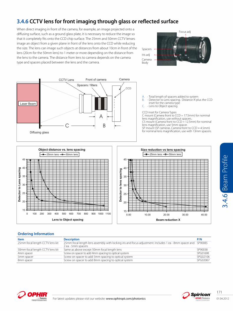
01.04.2012
171
For latest updates please visit our website: www.ophiropt.com/photonics
Beam
Pro
file
3.4.
6
3.4.6 CCTV lens for front imaging through glass or reflected surface When direct imaging in front of the camera, for example, an image projected onto a diffusing surface, such as a ground glass plate, it is necessary to reduce the image so that it completely fits onto the CCD chip surface. The 25mm and 50mm CCTV lenses image an object from a given plane in front of the lens onto the CCD while reducing the size. The lens can image such objects at distances from about 10cm in front of the lens (20cm for the 50mm lens) to 1 meter or more depending on the distance from the lens to the camera. The distance from lens to camera depends on the camera type and spacers placed between the lens and the camera.
A. - Total length of spacers added to systemB. - Detector to Lens spacing. Distance ‘A’ plus the CCD inset for the camera typeC. - Lens to Object spacing
CCD inset for Camera TypesC mount (Camera front to CCD = 17.5mm) for nominal lens magnification, use without spacers.CS mount (Camera front to CCD = 12.5mm) for nominal lens magnification, use 5mm spacer.SP mount (SP cameras. Camera front to CCD = 4.5mm) for nominal lens magnification, use with 13mm spacers.
Ordering InformationItem Description P/N25mm focal length CCTV lens kit 25mm focal length lens assembly with locking iris and focus adjustment. Includes 1 ea - 8mm spacer and
2 ea - 5mm spacers SP90085
50mm focal length CCTV lens kit Same as above except 50mm focal length lens SP900384mm spacer Screw on spacer to add 4mm spacing to optical system SPG016985mm spacer Screw on spacer to add 5mm spacing to optical system SPG021068mm spacer Screw on spacer to add 8mm spacing to optical system SPG02067
Spacers
Iris adj
CameraBody
Focus adj
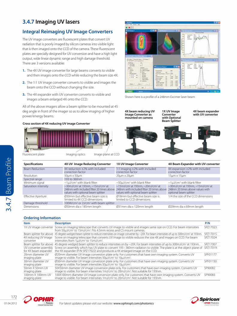
172
01.04.2012 For latest updates please visit our website: www.ophiropt.com/photonics
Beam
Pro
file
3.4.
7
3.4.7 Imaging UV lasers
Integral Reimaging UV Image ConvertersThe UV image converters are fluorescent plates that convert UV radiation that is poorly imaged by silicon cameras into visible light that is then imaged onto the CCD of the camera. These fluorescent plates are specially designed for UV conversion and have a high light output, wide linear dynamic range and high damage threshold. There are 3 versions available:
1. The 4X UV image converter for large beams converts to visible and then images onto the CCD while reducing the beam size 4X.
2. The 1:1 UV image converter converts to visible and images the beam onto the CCD without changing the size.
3. The 4X expander with UV converter converts to visible and images a beam enlarged 4X onto the CCD.
All of the above imagers allow a beam splitter to be mounted at 45 deg angle in front of the imager so as to allow imaging of higher power/energy beams.
4X beam reducing UV Image Converter as mounted on camera
1X UV Image Converter with Optional Beam Splitter
Shown here is a profile of a 248mm Excimer laser beam
Specifications 4X UV Image Reducing Converter 1X UV Image Converter 4X Beam Expander with UV converter
Beam Reduction 4X reduction ±2% with included correction factor
1:1 imaging ±2% with included correction factor
4X expansion ±2% with included correction factor
Resolution 50µm x 50µm 20µm x 20µm 15µm x 15µmSpectral range 193 to 360nmMinimum signal ~1µJ/cm2 with blank filter ~50µJ/cm2 with blank filter ~1µJ/cm2 with blank filterSaturation intensity ~30mJ/cm2 at 193nm, ~15mJ/cm2 at
248nm with included filter 20 times above values with optional beam splitter
~15mJ/cm2 at 193nm, ~20mJ/cm2 at 248nm with included filter 20 times above values with optional beam splitter
~30mJ/cm2 at 193nm, ~15mJ/cm2 at 248nm 20 times above values with optional beam splitter
Effective Aperture Ø30mm but effective beam size is limited to 4X CCD dimensions
Ø18mm but effective beam size is limited to CCD dimensions
1/4 the size of the CCD dimensions
Damage threshold 100W/cm2 or 2J/cm2 with beam splitterDimensions Ø50mm dia x 185mm length Ø31mm dia x 120mm length Ø29mm dia x 69mm length
4X beam expander with UV converter
Cross section of 4X reducing UV image Converter
Fluorescent plate Imaging optics Image plane at CCD
Ordering InformationItem Description P/N 1X UV image converter Screw on imaging telescope that converts UV image to visible and images same size on CCD. For beam intensities
from 50µJ/cm2 to 15mJ/cm2. Fits 4.5mm recess and CS mount cameras.SPZ17023
Beam splitter for above 45 degree wedged beam splitter to reduce intensities on image converter by ~20X. For beam intensities of up to 300mJ/cm2 at 193nm. SPZ170154X reducing UV image converter
Screw on imaging telescope that converts UV image to visible reduces the size 4X and images on CCD. For beam intensities from 1µJ/cm2 to 15mJ/cm2.
SPZ17024
Beam splitter for above 45 degree wedged beam splitter to reduce intensities on by ~20X. For beam intensities of up to 300mJ/cm2 at 193nm. SPZ17007UV converter assembly for 4X beam expander
Screw on assembly which has UV plate to convert 193 - 360nm radiation to visible. The plate is at the object plane of the 4X expander (P/N SPZ17022) and produces a 4X enlarged image on the CCD.
SPZ17019
20mm diameter UV imaging plate
Ø20mm diameter UV image conversion plate only. For customers that have own imaging system. Converts UV image to visible. For beam intensities 50μJ/cm2 to 10μJ/cm2.
SPF01177
30mm diameter UV imaging plate
Ø30mm diameter UV image conversion plate only. For customers that have own imaging system. Converts UV image to visible. For beam intensities 50μJ/cm2 to 10μJ/cm2.
SPF01150
50mm X 50mm UV imaging plate
50X50mm diameter UV image conversion plate only. For customers that have own imaging system. Converts UV image to visible. For beam intensities 1mJ/cm2 to 20mJ/cm2. Not suitable for 193nm.
SP90082
100mm X 100mm UV imaging plate
100X100mm diameter UV image conversion plate only. For customers that have own imaging system. Converts UV image to visible. For beam intensities 1mJ/cm2 to 20mJ/cm2. Not suitable for 193nm.
SP90083

01.04.2012
173
For latest updates please visit our website: www.ophiropt.com/photonics
Beam
Pro
file
3.4.
7
UView Ultraviolet Fixture for Camera Beam ProfilersThe UView Ultraviolet Beam Profiling accessory incorporates a fluorescent glass plate that converts incident UV light into green light allowing for measurement using standard silicon camera profilers. The UView accessory attaches to the GRAS 20 camera.
UView Sideways UView 3/4 View
Ordering InformationItem Description P/NUView Ultraviolet Fixture for Camera Profilers PH00226
Specifications
OpticalEntrance Aperture 18 × 22 mm; larger apertures optionalResolution 60µm; (larger for larger apertures)Wavelength Response 157 - 390 nmConverter Plate Spatial Uniformity Better than 3%System Spatial Uniformity ±3%Damage Fluence >100 mJ/cm2 @ λ= 248 nm, 200 Hz repetition rateSystem Saturation Exposure ~100 mJ/cm2 @ λ= 337 nm (iris fully open)Manual IrisLens Magnification 0.253Fluorescer Image size at array 4.55mm × 5.57mmMechanicalDimensions L × W × H 4.54 in. (11.50 cm) x 2.13 in. (5.41 cm) x 2.00 in. (5.08 cm)Mounting 3 orientations Standard ¼-20 thread; Optional M6 adapter;Temperature Range -20 to 60° C (4 to 140° F), non-condensing
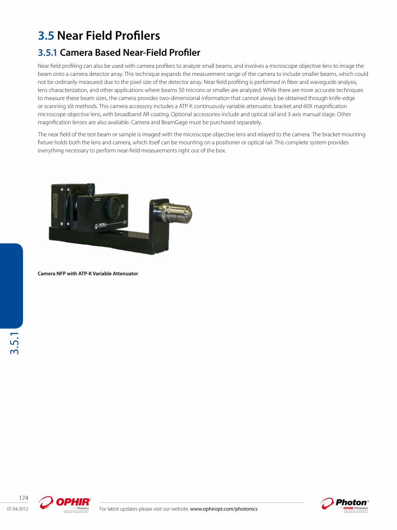
174
01.04.2012
Beam Profile
3.5.
1
3.5 Near Field Profilers3.5.1 Camera Based Near-Field ProfilerNear field profiling can also be used with camera profilers to analyze small beams, and involves a microscope objective lens to image the beam onto a camera detector array. This technique expands the measurement range of the camera to include smaller beams, which could not be ordinarily measured due to the pixel size of the detector array. Near field profiling is performed in fiber and waveguide analysis, lens characterization, and other applications where beams 50 microns or smaller are analyzed. While there are more accurate techniques to measure these beam sizes, the camera provides two-dimensional information that cannot always be obtained through knife-edge or scanning slit methods. This camera accessory includes a ATP-K continuously variable attenuator, bracket and 60X magnification microscope objective lens, with broadband AR coating. Optional accessories include and optical rail and 3-axis manual stage. Other magnification lenses are also available. Camera and BeamGage must be purchased separately.
The near field of the test beam or sample is imaged with the microscope objective lens and relayed to the camera. The bracket mounting fixture holds both the lens and camera, which itself can be mounting on a positioner or optical rail. This complete system provides everything necessary to perform near-field measurements right out of the box.
Camera NFP with ATP-K Variable Attenuator
For latest updates please visit our website: www.ophiropt.com/photonics

01.04.2012
175
For latest updates please visit our website: www.ophiropt.com/photonics
Beam
Pro
file
3.5.
2
Parameter NFP-VIS NFP-980 NFP-1550 NFP-Pyro
Tester Wavelength Range 400-700nm 700-1100nm 1300-1700nm 190->20μm<360nm optional
Lens Spread Function 0.49μm 1.1μm 2.6μm
Wavelength and application dependent for these parameters
Maximum Source 140μm 140μm 200μmObjective Focal Length 3mm 3mm 5.1mmObjective Rear Focal Distance 160mm 160mm 207mmObjective Numerical Aperture 0.85 0.85 0.48Objective Magnification 60:01:00 60:01:00 40:01:00NanoScan Model NSSI/9/5 NSGE/9/5 NSGE/9/5 NSPyro/9/5Aperture Size 9mm 9mm 9mm 9mmSlit Width 5μm 5μm 5μm 5μm3 Axis Stage Travel
X (across rail) 13mm micrometer adjustY (normal to rail) 6.5mm fine pitch actuatorZ (along rail) 13mm micrometer adjust
3.5.2 Slit-Based NanoScan Near-Field ProfilerMeasuring the near field of sources such as laser diodes, VCSELs, optical fiber, and/or waveguides can be a difficult task. Accurate measurement of such small sources to the micron level requires high precision in the optical and mechanical design. To simplify this task and to fill this requirement, Photon offers several models of Near-Field Profilers (NFPs) covering a wide range of wavelengths and power levels. Another important application of these instruments is to extend the focused laser spot size measurement range of the NanoScan profiler. By expanding the size of a focused spot it is possible to reduce the power density and make possible the measurement of beams that are too powerful to be measured without attenuation, as well as those that are too small to be accurately measured with the standard scanhead. The NanoScan NFPs are easy-to-use turnkey systems that can be used either as a stand-alone instrument or integrated into manufacturing inspection systems. For NanoScan users who want to extend the measurement capability of their present systems, the optical and mechanical components are also available as accessories.
The NFP-980 with 60:1 magnification and 1µm resolution, specifically designed for measurement of 980nm pump lasers, is also ideal for other applications in the wavelength range between 700nm–1100 nm. The NFP-1550, with 40:1 magnification and 2.6µm resolution, is designed for use in characterizing sources in the 1300-1600nm telecommunications wavelength band. Both models come with a NanoScan GE/9/5 scanhead and the magnifying objective lens, which can be rigidly mounted to an optional precision XYZ translation stage, which in turn is mounted to an optical rail. They also include the NanoScan Control and Data Acquisition Card and NanoScan Acquisition and Analysis Software. The system has all the standard Windows file saving, printing, communication and ActiveX capability.
For visible wavelengths, the NFP-VIS is equipped with the NanoScan SI/9/5 scanhead and the 60:1 microscope objective, AR coated for the 400–700nm wavelength range. UV Wavelengths below 360nm can also be accommodated with an optional UV corrected microscope objective. For higher power and longer wavelength beams the NFP-Pyro is available. These systems can measure spot sizes from 5μm at any wavelength from 190nm to 20μm. This instrument configuration naturally reduces the power density incident on the instrument by one over the square of the magnification. The system can be supplied with a lens for the user-specified wavelength of use.
For viewing VCSEL junctions, single-mode fibers and large long wavelength LD junctions there is an optional 100:1 objective lens option, producing diffraction limited performance from 400–700nm with a working distance of approximately 0.25-0.35mm and Numerical Aperture is 0.90. From 700–1600nm, this lens produces near diffraction-limited performance.
NanoScan Near-Field Profiler Systems

176
01.04.2012 For latest updates please visit our website: www.ophiropt.com/photonics
Beam
Pro
file
3.5.
2Ordering Information Item Description P/N Model USB NFP-1550(NS) Model NFP-1550 NanoScan system with Germanium Detector 9mm Aperture 5µm Slits. High-
resolution 63.5mm diameter head with rotation mount. Use from 700nm to 1.8micronsPH00229
Model USB NFP-980(NS) Model NFP-980 NanoScan Germanium Detector 9mm Aperture 5.0micron Slits. High-resolution 63.5mm diameter head with rotation mount. Microscope Objective Lens Mount with 60:1 optics for 700-1100nm
PH00230
Model USB NFP-VIS(NS) Model NFP-VIS NanoScan Silicon Detector 9mm aperture 5µm slits. High-resolution 63.5mm diameter head with rotation mount. Microscope Objective Lens Mount Bracket with 60:1 optics for 400-700nm
PH00231
Model USB NFP-Pyro NFP-NS-Pyro NanoScan pyroelectric detector with 9mm entrance 5µm slits. Use for wavelengths from 190mm to 20 microns (specify wavelengths of use when ordering). Lens Mount bracket with well-corrected aspheric high-energy 60:1 lens with a 0.68 NA. Available in wavelengths 400nm-1100nm
PH00232
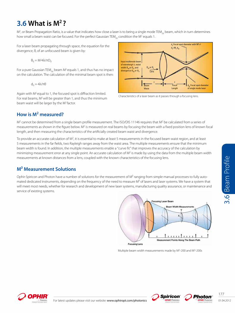
For latest updates please visit our website: www.ophiropt.com/photonics 01.04.2012
177
Beam
Pro
file
3.6
3.6 What is M2 ?M2, or Beam Propagation Ratio, is a value that indicates how close a laser is to being a single mode TEM
00 beam, which in turn determines
how small a beam waist can be focused. For the perfect Gaussian TEM00
condition the M2 equals 1.
For a laser beam propagating through space, the equation for the divergence, θ, of an unfocused beam is given by:
θ0 = M24λ/πD0
For a pure Gaussian TEM00
beam M2 equals 1, and thus has no impact on the calculation. The calculation of the minimal beam spot is then:
d0 = 4λ/πθ
Again with M2 equal to 1, the focused spot is diffraction limited. For real beams, M2 will be greater than 1, and thus the minimum beam waist will be larger by the M2 factor.
How is M2 measured?M2 cannot be determined from a single beam profile measurement. The ISO/DIS 11146 requires that M2 be calculated from a series of measurements as shown in the figure below. M2 is measured on real beams by focusing the beam with a fixed position lens of known focal length, and then measuring the characteristics of the artificially created beam waist and divergence.
To provide an accurate calculation of M2, it is essential to make at least 5 measurements in the focused beam waist region, and at least 5 measurements in the far fields, two Rayleigh ranges away from the waist area. The multiple measurements ensure that the minimum beam width is found. In addition, the multiple measurements enable a “curve fit” that improves the accuracy of the calculation by minimizing measurement error at any single point. An accurate calculation of M2 is made by using the data from the multiple beam width measurements at known distances from a lens, coupled with the known characteristics of the focusing lens.
M² Measurement SolutionsOphir-Spiricon and Photon have a number of solutions for the measurement of M² ranging from simple manual processes to fully auto-mated dedicated instruments, depending on the frequency of the need to measure M² of lasers and laser systems. We have a system that will meet most needs, whether for research and development of new laser systems, manufacturing quality assurance, or maintenance and service of existing systems.
Characteristics of a laser beam as it passes through a focusing lens.
Multiple beam width measurements made by M2-200 and M2-200s

178
01.04.2012 For latest updates please visit our website: www.ophiropt.com/photonics
Beam
Pro
file
3.6.
1
3.6.1 Camera Based Beam Propagation Analyzer: M2
M2-200s Automatically measure your beam quality in under 2 minutes Tune your laser for best operation ISO compliant Specifically developed for continuous usage Unequaled accuracy using patented UltracalTM
Calibration Automatic attenuation adjustment Pulsed and CW for most beam diameters and powers Compact and portable
Not all commercial M2 measuring instruments conform to the ISO 11146 method of employing a fixed position lens and moving detector. Instead, some manufacturers use a fixed position detector and a moving lens. If the laser beam is diverging or converging within the travel range of a moving lens, the reported M2 value and other results can be significantly compromised. Spiricon's M2-200s and M2-200 Beam Propagation Analyzers are fully ISO 11146 compliant.
Automatic M2 - at Production SpeedsThe M2-200s optical train uses a fixed position lens and camera. The mirrors that direct the focused beam into the camera are moved to precise locations, translating the beam through both the waist region and the far field regions. All these measurements and translations, as well as incremental beam attenuation, are automatically controlled by the M2-200s software. Software improvements in the M2-200s, including more efficient algorithm execution, has decreased the measurement reporting time by 2-3 times, making it possible to report M2 in under two minutes.
Beam Attenuater
Laser Source
Steering Mirrors
1st
2nd
CameraAlignment Tool
M2-200/200s Optical Train
“A” “B”

01.04.2012
179
For latest updates please visit our website: www.ophiropt.com/photonics
Beam
Pro
file
3.6.
1
Accuracy by DesignSpiricon products are known for accuracy. Using our patented UltracalTM calibration method and auto aperturing to exclude noise beyond the wings of the laser beam, assures the user of the most accurate measurements in the industry.
Designed by Our CustomersSpiricon has redesigned the M2-200, the world's top selling beam propagation system to include customer input, increased attention to durability, and operational robustness for continuous use applications - three shifts a day, seven days a week. Novice and seasoned users will appreciate these new features along with the time-tested excellence that the Spiricon M2-200 measurement system has provided over the years.
Main Screen Functions
This window displays quantitative measurements of the laser parameters. These include the X and Y beam widths, M2 or K, the divergence angles, the Rayleigh range, and other parameters shown.
This window presents measurements of beam width vs. position for a given run. After measuring a few points, the software extrapolates a curve fit. The Xs and Ys represent individual measurement points. The solid lines present the best fit hyperbola of the beam propagation equation to the measured points. The M2 and other laser parameters are computed from the best fit hyperbola since it provides a smoothing of the data points.
The 2D or 3D beam profile of the currently measured point in the beam propagation curve. This image enables visual intuitive verification of the beam profile behavior through focus. After each run the user can click any individual measured point and observe the beam profile. Outlying or anomalous points can be automatically or manually excluded from the curve fit calculations for more accurate results.
Laser Source
Mirror 2
Mirror 1
Lens Filters
Camera
Manual M2
Manual mode is available for beams that are too large or too small or at wavelengths outside the standard optical train.
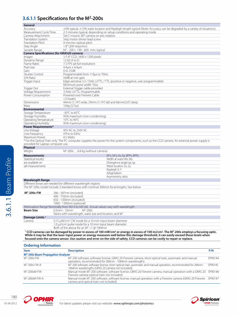
180
01.04.2012 For latest updates please visit our website: www.ophiropt.com/photonics
Beam
Pro
file
3.6.
1.1
3.6.1.1 Specifications for the M2-200sGeneralAccuracy ±5% typical, ±12% waist location and Rayleigh length typical (Note: Accuracy can be degraded by a variety of situations) Measurement Cycle Time 2-3 minutes typical, depending on setup conditions and operating mode Camera Attachment Std C-mount, 90° camera on axis rotation Translation System Step motor-driven lead screw Translation Pitch 4 mm/rev optical pitch Step Angle 1.8° (200 steps/rev) Sample Range M2 - 200 s 190 - 600 mm, typical Camera Specifications (for GRAS20 camera)Imager 1/1.8” CCD, 1600 x 1200 pixelsDynamic Range 12 bit A to D Frame Rates 7.5 FPS (at full resolution) Pixel size 4.4µm x 4.4µm Gain 0 to 25dB Shutter Control Programmable from 110µs to 70ms S/N Ratio 59dB at min gain Trigger Input Edge sensitive 3.3 / 5Vdc LVTTL / TTL (positive or negative, user programmable)
Minimum pulse width 10us Trigger Out External Trigger cable provided Voltage Requirement 3.3Vdc LVTTL, Programmable Power Consumption Powered over Firewire Cable
<3.5watts Dimensions 44mm (1.74") wide, 29mm (1.14") tall and 66mm(2.6") deep Mass 104g (3.7oz)Environmental Storage Temperature -30°C to 65°C Storage Humidity 95% maximum (non-condensing) Operating Temperature 10°C to 40°C Operating Humidity 95% maximum (non-condensing)Power Requirements* Line Voltage 95V AC to 250V AC Line Frequency 47Hz to 63Hz Maximum Power 4.5 Watts* For the Optical Train only. The PC computer supplies the power for the system components, such as the CCD camera. An external power supply is provided for Laptop computer use.PhysicalWeight M2-200s… 6.8 kg (without camera) Measurements M2x, M2y, Kx, Ky, BPPx, BPPy
Statistical results) Width at waist Wx, Wyare available on Divergence angle qx, qy(all measurements Waist location Zx, Zy
Rayleigh X, YAstigmatismAsymmetry ratio
Wavelength Range Different lenses are needed for different wavelength regionsThe M2-200s model include 3 standard lenses with nominal 300mm focal lengths. See below
M2-200s-FW 266 - 587nm (included)400 - 750nm (included)650 - 1300nm (included)1000 - 1300nm (optional)
Attenuation Range Nominally from ND 0 to ND 4.8. Actual values vary with wavelengthBeam Size 0.5mm - 10mm M2-200s
Varies with wavelength, waist size and location, and M2
Damage Limits 1 Camera 0.15 µW/cm2 CW mode for a 10 mm input beam diameter
1.0 µJ/cm2 pulse mode for a 10 mm input beam diameterBoth of the above for an M2 =1 @ 1064nm
1 CCD cameras can be damaged by power in excess of 100 mW/cm2 or energy in excess of 100 mJ/cm2. The M2-200s employs a focusing optic. While it may be that the laser input power or energy measures well below this damage threshold, it can easily exceed these levels whenfocused onto the camera sensor. Use caution and error on the side of safety. CCD cameras can be costly to repair or replace.
Ordering Information Item Description P/N M2-200s Beam Propagation Analyzer M2-200s-FW M2-200 software, software license, GRAS 20 Firewire camera, short optical train, automatic and manual
operation, recommended for 266nm - 1064nm wavelengthsSP90144
M2-200s-FW-A M2-200 software, software license, short optical train, automatic and manual operation, recommended for 266nm - 1064nm wavelengths (GRAS 20 camera not included)
SP90145
M2-200sM-FW Manual mode M2-200 software, software license, GRAS 20 Firewire camera, manual operation with a GRAS 20 Firewire camera (optical train not included)
SP90146
M2-200sM-FW-A Manual mode M2-200 software, software license, manual operation with a Firewire camera (GRAS 20 Firewire camera and optical train not included)
SP90147
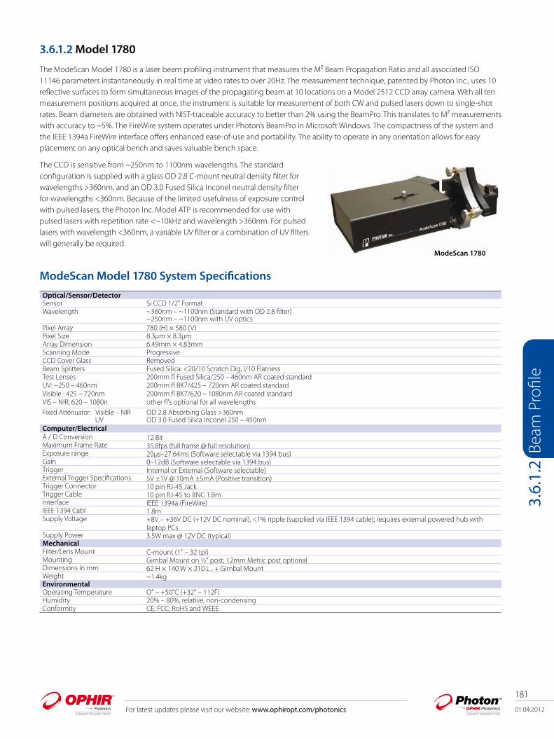
01.04.2012
181
For latest updates please visit our website: www.ophiropt.com/photonics
Beam
Pro
file
3.6.
1.2
3.6.1.2 Model 1780
The ModeScan Model 1780 is a laser beam profiling instrument that measures the M² Beam Propagation Ratio and all associated ISO 11146 parameters instantaneously in real time at video rates to over 20Hz. The measurement technique, patented by Photon Inc., uses 10 reflective surfaces to form simultaneous images of the propagating beam at 10 locations on a Model 2512 CCD array camera. With all ten measurement positions acquired at once, the instrument is suitable for measurement of both CW and pulsed lasers down to single-shot rates. Beam diameters are obtained with NIST-traceable accuracy to better than 2% using the BeamPro. This translates to M² measurements with accuracy to ~5%. The FireWire system operates under Photon’s BeamPro in Microsoft Windows. The compactness of the system and the IEEE 1394a FireWire interface offers enhanced ease-of-use and portability. The ability to operate in any orientation allows for easy placement on any optical bench and saves valuable bench space.
The CCD is sensitive from ~250nm to 1100nm wavelengths. The standard configuration is supplied with a glass OD 2.8 C-mount neutral density filter for wavelengths >360nm, and an OD 3.0 Fused Silica Inconel neutral density filter for wavelengths <360nm. Because of the limited usefulness of exposure control with pulsed lasers, the Photon Inc. Model ATP is recommended for use with pulsed lasers with repetition rate <~10kHz and wavelength >360nm. For pulsed lasers with wavelength <360nm, a variable UV filter or a combination of UV filters will generally be required.
ModeScan 1780
ModeScan Model 1780 System Specifications
Optical/Sensor/DetectorSensor Si CCD 1/2" FormatWavelength ~360nm – ~1100nm (Standard with OD 2.8 filter)
~250nm – ~1100nm with UV opticsPixel Array 780 (H) × 580 (V)Pixel Size 8.3µm × 8.3µmArray Dimension 6.49mm × 4.83mmScanning Mode ProgressiveCCD Cover Glass RemovedBeam Splitters Fused Silica: <20/10 Scratch Dig, l/10 FlatnessTest LensesUV: ~250 – 460nmVisible : 425 – 720nmVIS – NIR; 620 – 1080n
200mm fl Fused Silica/250 – 460nm AR coated standard 200mm fl BK7/425 – 720nm AR coated standard200mm fl BK7/620 – 1080nm AR coated standardother fl's optional for all wavelengths
Fixed Attenuator: Visible – NIR UV
OD 2.8 Absorbing Glass >360nmOD 3.0 Fused Silica Inconel 250 – 450nm
Computer/ElectricalA / D Conversion 12 BitMaximum Frame Rate 35.8fps (full frame @ full resolution)Exposure range 20µs–27.64ms (Software selectable via 1394 bus)Gain 0–12dB (Software selectable via 1394 bus)Trigger Internal or External (Software selectable)External Trigger Specifications 5V ±1V @ 10mA ±5mA (Positive transition)Trigger Connector 10 pin RJ-45 JackTrigger Cable 10 pin RJ-45 to BNC 1.8m Interface IEEE 1394a (FireWire)IEEE 1394 Cabl 1.8mSupply Voltage +8V – +36V DC (+12V DC nominal), <1% ripple (supplied via IEEE 1394 cable); requires external powered hub with
laptop PCsSupply Power 3.5W max @ 12V DC (typical)Mechanical Filter/Lens Mount C-mount (1" – 32 tpi)Mounting Gimbal Mount on ½" post; 12mm Metric post optionalDimensions in mm 62 H × 140 W × 210 L , + Gimbal MountWeight ~1.4kgEnvironmentalOperating Temperature O° – +50°C (+32° – 112F)Humidity 20% – 80%, relative, non-condensingConformity CE; FCC; RoHS and WEEE

182
01.04.2012 For latest updates please visit our website: www.ophiropt.com/photonics
Beam
Pro
file
3.6.
1.2
Item Description P/N
ModeScan 1780 M2 System with Fire Wire BeamProMS-1780 ModeScan Model 1780, dedicated M² measurement system, with 12-bit FireWire (IEEE 1394a) CCD
detector for single-shot, pulsed and CW lasers. System includes: ModeScan with gimbaled mount for alignment; FireWire CCD camera; Photon FireWire BeamPro Acquisition and Analysis Software stand-alone GUI with M² Analysis; Active X automation interface; 200mm lens coated for Visible range (400–700nm); OD 2.8 glass filter for operation >360nm; Dimensions: 62mm x 140mm x 210mm; For use from 250–1100nm wavelengths - UV and NIR operation will require additional specifically coated optics.
PH00096
MS 1780 Lens Kits All lens kits contain 200mm, 250mm, 400mm, 500mm, 750mm and 1m focal length coated lens with mounting hardware and MS-Tube Kit.
MS-NIR Kit Set of lenses coated for operation in NIR (700–1100nm) PH00111MS-VIS Kit Set of lenses coated for operation in VIS (400–700nm) PH00194MS-UV Kit Set of lenses coated for operation in UV (250–400nm) PH00097MS-YAG Kit Set of all the available lenses for all wavelengths (MS-NIR,VIS and UV Kits combined) and MS-Tube Kit PH00118MS-TUBE Kit Set of C-Mount tubes to mount lenses to the MS-1780. Includes 100mm, 50mm, 40mm, 25mm, 10mm
and 50-90mm adjustable focusing tubePH00127
ModeScan 1780 AccessoriesUV Lens Kit UV lenses are all fused silica plano-convex and coated for UV wavelengths 250-400nm PH00097UV200 200mm focal length lens PH00098UV250 250mm focal length lens PH00099UV350 350mm focal length lens PH00100UV500 500mm focal length lens PH00101UV750 750mm focal length lens PH00102UV1000 1000mm focal length lens PH00103MS-VIS Lens Kit Visible (VIS) lenses are all BK 7 plano-convex and coated for visible wavelengths 450–650nm PH00104VIS200 200mm focal length lens PH00105VIS250 250mm focal length lens PH00106VIS400 400mm focal length lens PH00107VIS500 500mm focal length lens PH00108VIS750 750mm focal length lens PH00109VIS1000 1000mm focal length lens PH00110MS-NIR Lens KitNIR200 200mm focal length lens PH00112NIR250 250mm focal length lens PH00113NIR400 400mm focal length lens PH00114NIR500 500mm focal length lens PH00115NIR750 750mm focal length lens PH00116NIR1000 1000mm focal length lens PH00117Extension and Focusing TubesCM-EXT100 100mm long C-Mount extension tube for mounting lenses outside ModeScan 1780 Box PH00119CM-EXT50 50mm long C-Mount extension tube for mounting lenses outside ModeScan 1780 Box PH00120CM-EXT40 40mm long C-Mount extension tube for mounting lenses outside ModeScan 1780 Box PH00121CM-EXT25 25mm long C-Mount extension tube for mounting lenses outside ModeScan 1780 Box PH00122CM-EXT10 10mm long C-Mount extension tube for mounting lenses outside ModeScan 1780 Box PH00123FOCTUBE20-30 C-Mount fine thread focus tube with 20–30mm adjustable length for focus of lenses mounted to
extension tubesPH00124
FOCTUBE30-50 C-Mount fine thread focus tube with 30–50mm adjustable length for focus of lenses mounted to extension tubes
PH00125
FOCTUBE50-90 C-Mount fine thread focus tube with 50–90mm adjustable length for focus of lenses mountedto extension tubes
PH00126
MS-TUBE Kit Tube Kit for MS-1780 PH00127
Ordering Information
Arrangement of Measurement Windows: Video
Window Beam Propagation Mode; Beam Statistics
Window; Horizontal and Vertical Caustics Window.

01.04.2012
183
For latest updates please visit our website: www.ophiropt.com/photonics
Beam
Pro
file
3.6.
2
3.6.2 Slit - Based Beam Propagation Analyzer M2
NanoModeScanFor lasers with wavelengths in the UV and IR ranges which are either difficult or impossible to measure with a CCD based profiler, Photon has the Model 1740 NanoModeScan, which is also a dedicated, fully automated M² system using the NanoScan slit profiler to make the measurements according to the ISO 11146. The ISO method requires that the user input ten measurement points along the axis of propagation, five around the waist and five measurement points that are at least two Rayleigh ranges distal to the test lens. Once these have been set up, the NanoModeScan can make the entire M² measurement in as little as 20 seconds. The dedicated NanoModeScan software reports the M², the beam waist diameter and location, divergence, and the beam’s Rayleigh range for each axis. The NanoModeScan’s speed of analysis is due to the wide dynamic range of the NanoScan slit profiler, which does not require that the attenuation be changed during the measurement of both the waist and far-field areas of the beam propagation.
The NanoModeScan can also determine the M² using the Rayleigh Method as a fully automated process. By selecting the Rayleigh method, the ModeScan will find the waist and then the Rayleigh points for both axes. It will then report the propagation parameters as with the ISO method. This method is fully automated and requires no intervention from the operator, other than the initial set up and input of the wavelength and lens parameters. It does take longer than the ISO method to make the measurements since it must find the waist and Rayleigh points on its own. The time required for the entire measurement is dependent on the laser being measured, but is usually no more than 2 or 3 minutes. It has the advantage of being fully automated and can be left to run while the operator does some other task.
The NanoModeScan is available with the Silicon, Germanium, or Pyroelectric NanoScan profiler, making it the only system that can measure M2 for lasers at any wavelength from <200nm to beyond 10.6µm.
NanoModeScan SpecificationsSensor/DetectorScan head Travel 500mm Optical Axis Height 140-170mmHorizontal Fine Adjustment 19mmAngular Fine Adjustment ±2º vertical, ±1.4º horizontalStandard Lenses 200mm EFL, BK-7 plano-convex, Broadband AR Coated
400mm EFL, BK-7 plano-convex, Broadband AR Coated; UV through long IR lenses available Optional Lens 200mm FL fused silica for UV coated for wavelength of use
350mm FL fused silica for UV coated for wavelength of use190mm FL IR lens for 10.6μm wavelength
Minimum Spot Size See scan head specifications Computer/ElectricalSource Power See scan head specificationsFile Saving and Data Logging Data files, ASCII FilesAC Power 110V, 60Hz standard
220V, 50Hz optionalCommunication RS-232 Interface or USB to RS-232 adapter requiredMechanical (Dimensions in mm) NanoModeScan Linear Stage 812 × 102 × 78Photon Motion Controller 273 × 89 × 57Alignment Channel 940 × 247 × 72Removable Light Shield 787 × 777 × 110Weight
NanoModeScan Linear Stage 8.4kg Photon Motion Controller 1.5kgAlignment Channel 4.8kg
NanoModeScan

184
01.04.2012 For latest updates please visit our website: www.ophiropt.com/photonics
Beam
Pro
file
3.6.
2
Item Description P/N
NanoModeScan M2 SystemsUSB MSP-NS-Si/9/5 Model 1740 ModeScan with NanoScan Silicon (Si ) Detector 9mm aperture 5μm slits Si detector,
63.5mm diameter head, 9mm entrance aperture, and matched pair of 5.0μm wide slits. Use from 190 to 1000nm wavelengths.
PH00233
USB MSP-NS-Ge/9/5 Model 1740 ModeScan with NanoScan Germanium (GE) Detector 9mm aperture 5.0μm slits. Germanium detector, 63.5mm diameter head, 9mm entrance aperture, and matched pair of 5.0μm wide slits. Use from 700nm to 1.8μm wavelength.
PH00234
USB MSP-NS-Pyro/9/5 Model 1740 ModeScan with NanoScan Pyroelectric Detector 9.0mm aperture 5μm slits. Pyroelectric detector, 63.5mm diameter head, 9mm entrance aperture, and matched pair of 5µm wide slits.
PH00235
MSP-NS-Pyro/20/25 Model 1740 ModeScan with HP NanoScan scanhead with 9mm Pyroelectric Detector 5μm slits, 100mm diameter head, 9 mm entrance aperture, and matched pair of 5μm wide slits; scanhead is fan cooled.
PH00218
USB MSP-HPNS/10/5 Model 1740 ModeScan with HP NanoScan scanhead with 9mm Pyroelectric Detector 5μm slits,100mm diameter head, 9 mm entrance aperture, and matched pair of 5μm wide slits; scanhead is fancooled.
PH00236
NanoModeScan AccessoriesLENS 200 UV-XXX Optional 200mm quartz lens for use between 190–400nm wavelengths. PH00090LENS 400 UV-XXX Optional 400mm quartz lens for use between 190–400nm wavelengths. PH00091LENS 190 10.6 Optional 7.5-inch focal length lens for use at 10.6µm wavelength. PH00092LENS 100 VIS Optional 100 mm focal length lens for use 400–700nm wavelength. PH00093LENS 100 NIR Optional 100 mm focal length lens for use 650–1000 nm wavelength. PH00094LENS 100 LIR Optional 100 mm focal length lens for use 1000–1550nm wavelength. PH000951740 LENS MNT Lens mount for users wanting to use their own 25mm diameter lens. PH00075CUSTOM LENS Specify wavelength, focal length PH00088Model 1740 ModeScan Rail w/o scan head PH000741740 LENS PREP ModeScan custom lens PH000761740 TRNG ModeScan onsite operation training PH00077Lens 400 2um Optional 400mm focal length lens for use at @2µm wavelength PH00224Lens 200mm VIS Optional 200mm focal length lens for use 400-700nm wavelength PH00237Lens 400mm VIS Optional 400mm focal length lens for use 400-700nm wavelength PH00238Lens 200mm NIR Optional 200mm focal length lens for use 650-1000nm wavelength PH00239Lens 400mm NIR Optional 400mm focal length lens for use at 650-1000nm wavelength PH00240Lens 200mm LIR Optional 200mm focal length lens for use at 1000-1550nm wavelength PH00241lens 400mm LIR Optional 400mm focal length lens for use at 1000-1550nm wavelength PH00242
Ordering Information - NanoModeScan M² Systems
All NanoModeScan Systems include (unless otherwise noted): High-resolution scanhead with rotation mount. Two BK 7 lenses and mounts. Standard are 200 and 400mm focal length. Lens coating Choices:
- VIS Visible: 430–700nm (not for use with Germanium detector)- NIR Near IR: 650–1000nm - LIR Long IR: 1000–1550nm (not for use with Silicon detector)
VLIR: Very long infrared >1550nm. The two glass lenses will not be included but instead credited toward the very long wavelength IR lens or lenses that will require an optional charge (for use with MSP-NS-Pyro/9/5 only).
OPTIONAL UV: If ultraviolet application, the two glass lenses will not be included; instead we will send one 200 mm focal length lens coated for wavelength of use.
Be sure to specify XXX wavelength when ordering.
Example of NanoModeScan Alignment Screen Example of NanoModeScan Measurement Screen

01.04.2012
185
For latest updates please visit our website: www.ophiropt.com/photonics
Beam
Pro
file
3.7.
1
3.7 Integrated Laser Performance Measurements3.7.1 Beam Cube - Beam Profiling/Power/Focus Spot Position/Temporal Pulse Shape BA- 500 - Integrated Beam Profiling/Power/Energy/Frequency/Temporal Pulse ShapeFeatures Monitor all important beam parameters to keep tight control over process Powers up to 1500W, energies up to 100J and beam diameters up to 30mm or focal spots down to 50µm Portable - can be moved from laser to laser to monitor all lasers in plant BA500 measures beam profile, temporal pulse shape, power, energy and frequency up to 1500W. For collimated beams only Beam Cube measures beam profile, focal spot position, temporal pulse shape and power, up to 150W For measuring at or near focal spot
BA 500
Beam Cube

186
01.04.2012 For latest updates please visit our website: www.ophiropt.com/photonics
Beam
Pro
file
3.7.
1
The Beam Cube and BA500 are comprehensive laser beam analysis systems for pulsed industrial Nd:YAG and Diode lasers for monitoring all important laser beam parameters so as to obtain reproducible laser cutting/welding process results. While intended for pulsed industrial lasers they can also accommodate cw beams. These systems measure average power, energy per pulse, spatial beam profile and temporal beam profile. All these quantities can be recorded in digital form for storage and analysis. The Beam Cube is a self contained device that is tailored for industrial Nd:YAG or Diode laser systems of up to 150W. There is no need for the user to add any beam modifying beam splitters, attenuators or other components. The compact system easily fits into typical installations and is designed for vertical or horizontal laser beams. The Beam Cube can image the focal spot or a point on the beam not near the focus where the imaged cross section does not exceed ~3mm. It magnifies the beam 2 - 3 times depending on which lens is used so as to get the most resolution of the spot monitored. The lens is externally mounted so it can easily be switched. The lens can also be removed to measure collimated beams of up to 7mm in size. The BA500 is a larger self contained device that is tailored for industrial Nd:YAG or Diode laser systems of up to 1500W. It is designed to image parallel beams of up to 30mm diameter and reduces the beam 7X.
Diagnostic Capabilities: Spatial Beam ProfileThe BA500 and Beam Cube show you the intensity profile of your beam in real time and allow you to adjust your laser resonator and beam delivery optical system for optimum beam quality on line. You can also measure the cross section at any point as shown. The illustration shows the intensity distribution of a pulsed Nd:YAG laser where the X and Y profiles are taken at the cursor lines which can be placed anywhere on the beam. This data can be saved, brought back and manipulated at any time so you can compare the present profile with a reference. These systems all have an exclusive optical system making it easy for you to adjust the intensity to get the optimum picture by just pushing and pulling the attenuating filter adjustment levers. The beam profile can also be shown in a three-dimensional form which can be rotated to different angles and elevations.
Temporal Pulse ShapeThe temporal profile of laser pulses, important in obtaining consistent process results, can now be easily monitored. Shown to the right is the pulse shape of the same pulsed Nd:YAG laser with 2ms pulses. It is being measured with a PC oscilloscope available as an accessory. You can display the pulse shape alone or together with the beam profile on your PC. Alternately, plug the BA500 or Beam Cube output into an oscilloscope to observe the temporal pulse shape of your laser beam.

01.04.2012
187
For latest updates please visit our website: www.ophiropt.com/photonics
Beam
Pro
file
3.7.
1
Average Laser PowerWith the Ophir USB Interface between the BA500 and Beam Cube unit and your PC or laptop, you can measure the average power of your laser to an accuracy of ± 3%. The BA500 RP power/energy measuring head has an exclusive damage resistant coating with a damage threshold of 3kW/cm2.
Energy per Pulse and FrequencyThe patented RP head inside the BA500 is able to measure the energy per pulse and the frequency of the laser to high accuracy. With the USB Interface you can display this on your PC or laptop screen.
StatisticsThe Beam Cube/BA500 with USB Interface is able to record and store an unlimited number of points in your PC. The software provided has a number of ways of displaying the statistics of the data.
Schematic setup of a BA500 system
Laptop or desktop PC screen showing spatial beam profile, temporal profile, power, energy and frequency
BA500 unit
PC scope unit (optional)
USB Interface
USB2 port
Water flow Laser in
Simplified Schematic of Beam Cube System
Beam splitter assembly (simplified)
Host Laser SystemInput from laser
bending mirror and focusing lens
Beam Cube
Adjustment rods
Optical trigger for automatic synch with pulsed lasers and temporal profile
Variable attenuator
CCD beamprofiler
RP power/energy/temporal profile head
Beam Cube Input lens

188
01.04.2012 For latest updates please visit our website: www.ophiropt.com/photonics
Beam
Pro
file
3.7.
1
Specifications
General Beam Cube BA500Max and min average power 1W to 100W continuous and to 150W for
up to 1 min10W to 1500W
Maximum average power density (a), (c) 4kW/cm2 at entrance window 4kW/cm2 at entrance window
Max and min energy 20mJ (b) to 100Joules 100mJ (b) to 100 JoulesMaximum energy density and repetition rate at entrance window vs. pulse width
pulse width max energy density max energy density max rep rate for energy measurement
10ms 20J/cm2 150J/cm2 80Hz2ms 5J/cm2 40J/cm2 800Hz0.5ms 1.5J/cm2 8J/cm2 1kHz
Cooling System Conduction cooled Water-cooled Min flow rate: 2.5 liter/minDimensions 22cm L x 16cm W x 14cm H 33cm L x 18cm W x 14cm HSpectral Range 400 - 1100nm (calibrated for 1064nm) 800 – 1064nm (calibrated for 1064nm and 800nm)Beam profiler unitCamera Standard Beam Cube: SP503U 640x480
pixel camera with 9.9µm spacing Beam Cube 620: SP620U 1600x1200 pixel camera with 4.4µm spacing
SP620U 1600x1200 pixel camera with 4.4µm spacing
PC interface USB2 USB2Shutter speeds Continuously variable 1/frame rate to 1/6,000, manual or automaticGain control 0dB to 27dB in ~700 steps (each step is ~0.035dB). Manual or automatic control.
Frame rate at 640x480 pixel ROI Std Beam Cube: 60Hz. Auto synch with laserBeam Cube 620: 20Hz. Auto synch with laser
20Hz, auto synch with laser
Software features Automatic gain and shutter control. Peak and Centroid position tracking. 2D and 3D contour map. Sophisticated noise and background control. Best fit to gaussian or top hat profile 3D display viewable from any angle or elevation. Store and recall screens in single or video fashion. 3 different measures of beam width, of peak, 4 sigma and 90/10 knife edge. Save numerical data files of profiles. Log data with time. Full on line instructions and help. Fully flexible screen format.
Minimum PC system requirements Pentium-4 2GHz, 256 MB Memory, Operating system, Windows XP Service Pack 2 or Vista 32.Intensity adjustment Continuously variable filters actuated from outside the unit.System optical performanceField of view ±6° ±2.5°Maximum beam size Ø22mm at entrance for converging beam,
Ø7mm for collimated beamsØ30mm
Beam reduction or expansion Expanded 2-3X . With no lens 1X Reduced 7XResolution ~5µm ~80µmPower / energy / temporal profile unitTemporal pulse shape response time into oscilloscope
200µs resp. time. Maximum peak power 1000W.
1µs resp. time. Maximum peak power 10,000W
Software functions with USB Interface connected to PC or laptop
average power, statistics average power, energy per pulse, pulse rate, statistics, missing pulses
Data logging Can send unlimited number of points in real time to PC via USB Interface at >1000 point/s. Windows software provided for data analysis.
Notes: (a) The power density limitation applies to any surface that the beam hits. For Beam Cube, since the object plane is outside the instrument, focal spots of much higher power density can be imaged as long as the power density limit on the optical surfaces is not exceeded. Notes: (b) The BA500 will not resolve pulses of energy below 100mJ unless the pulse rate is high. If the energy deposited in 1/50th of a second exceeds 100mJ, then the unit will be able to show the pulses even though the individual energies are below 100mJ. The same applies to the Beam Cube except the minimum is 20mJ.Notes: (c) If the beam power or energy density on the entrance window exceeds specifications, the window can be removed and not used, assuming that the power and energy density on the first beam splitter is below the damage threshold.
Ordering InformationItem Description Ophir P/NBeam Cube 503 To be used with oscilloscope of Beam Cube system for beam profile, pulse shape, power and energy.
user’s choice. Includes -100mm lens assembly. Uses SP503 beam profiling cameraSP786015
Beam Cube 620 Same as above but with higher resolution SP620 camera SP786016 Replacement -100mm lens assembly Replacement -50mm lens assembly for Beam Cube SPZ08256 -50mm lens assembly Optional -50mm lens assembly for Beam Cube SPZ08255BA500-V2 BA500-V2 system for beam profile, pulse shape, power and energy To be used with oscilloscope of
user’s choiceSP786013
Optional Carrying case for BA500 Carrying case for BA500 unit, optional oscilloscope and cables 1J02048 Optional PC oscilloscope 1MHz virtual oscilloscope for Beam Cube or BA500 to turn your PC into an oscilloscope displaying the
temporal pulse shape. Uses PC or laptop USB portSPE10008
Optional USB Interface USB Interface for displaying the laser power on your PC 7Z01200

01.04.2012
189
For latest updates please visit our website: www.ophiropt.com/photonics
Beam
Pro
file
3.8.
1
3.8 High-Power Applications3.8.1 High-Power NanoScanPhoton’s High-Power NanoScan can measure focused CO
2 laser beams up to 5 kilowatts. The High-Power NanoScan is equipped with a
pyroelectric detector with copper slits and drum. A cooling fan mounted on the scan head body provides additional heat management. With the new “peak connect” algorithm and the software controlled variable scan speed, the High-Power NanoScan is ideal for measuring lasers operating with pulse width modulation (PWM) power control. Measurement of Q-switched lasers and other higher frequency pulsed lasers is also possible using this feature.
What Can be Measured?Measuring high-power beams can be tricky. The lasers have the potential to damage the scan head, and any reflected light can be dangerous to both the operator and the surroundings. The High-Power NanoScan can measure these beams because it uses a combination of highly reflective components with high thermal dissipation capability. It is important to manage the reflected beam so that it neither reenters the laser cavity nor sends stray beams into the surrounding area. The scan head is designed to make short duration measurements to avoid excessive heating of components. The head should be only in the incident beam for 10 to 60 seconds depending on the power levels to prevent excessive heating of the components. The High-Power NanoScan scan head has been shown to be able to handle power densities of 3.2MWcm-2 at 10.6µm, the power density of a 200µm beam at 1kW. At the shorter wavelengths of the other common industrial lasers, Nd:YAG and DPSS, the upper limits are a little less, due to the slightly lower reflectivity of the components at wavelengths around 1000nm. Visible and UV lasers can also be measured, but these will have lower limits yet.
The chart below shows the damage thresholds for pulsed beam energies for the three wavelength regimes. The lines represent the maximum energies per pulse for various spot sizes that correspond to 5J/cm2 for the 3µm to 100µm wavelengths, 2.5J/cm2 for the 700nm to 3µm range, and 250mJ/cm2 for the UV-Visible range from 190nm to 700nm. When operating with pulsed lasers, calculate the energy per pulse to ensure that the values fall below these lines for the wavelength of the laser. Operation above these values will likely cause damage to the scan head apertures.
High-Power NanoScanwith cooling fan
Minimum Beam Size per Pulse Frequency
NanoScan Large Drum (HP)
Rotation Rate (Hz) 1.25 2.50 5.00 10.00
Slit Speed (µm/msec) 233.25 466.50 933.01 1866.01
Data Points per Profile 15 15 15 15
Pulse Frequency (kHz) Minimum Beam Diameter in μm0.5 6998 13995 N/A N/A1 3499 6998 13995 N/A2 1749 3499 6998 139953 1166 2333 4665 93304 875 1749 3499 69985 700 1400 2799 55986 583 1166 2333 46657 500 1000 1999 39998 437 875 1749 34999 389 778 1555 311010 350 700 1400 279911 318 636 1272 254512 292 583 1166 233313 269 538 1077 215314 250 500 1000 199915 233 467 933 186616 219 437 875 174917 206 412 823 164618 194 389 778 155519 184 368 737 147320 175 350 700 140021 167 333 666 133322 159 318 636 127223 152 304 608 121724 146 292 583 116625 140 280 560 112050 70 140 280 560100 35 70 140 280150 23 47 93 187

190
01.04.2012 For latest updates please visit our website: www.ophiropt.com/photonics
Beam
Pro
file
3.8.
1
Ordering Information - High-Power NanoScan
All High-Power NanoScan Systems Include: Fan cooled scanhead. For use at wavelengths from 200nm to greater than 20μm. Maximum power capacity is dependent on wavelength and spot size. Refer to operating space charts for more information. Slits and scan drum are highly reflective and user must send reflected energy into appropriate dump. A direct back reflection may cause laser cavity to oscillate or if not properly directed may cause damage. User must handle all back-reflected energy from laser.NanoScan Integrated Software package. Software for use with NanoScan under Microsoft Windows (32 Bit version only) 2000 Professional, XP Professional, Vista and windows 7 (32/64) operating systems.Measurements include: spot size, position and position difference information and laser profiles. Includes “peak connect” and software control of scan speed for measurement of pulsed and pulse width modulated (PWM). Software includes ability to capture and record bursts of data and ActiveX automation.USB 2.0 controller replaces the PCI bus card and allows NanoScan to interface to USB 2.0 port of laptop or desktop PC. Performance of Certificate of Calibration traceable to National Institute of Standards and Testing (NIST) to better than ±3%.
Detector Type Power Range Wavelength Aperture Slits Scan Head Size
Pyroelectric ~1W - ~5W upper limit dependent on wevelength
190nm - > 100μm
9mm 5μm 100mm
Pyroelectric Large Aperture
~1W - ~5W upper limit dependent on wevelength
190nm - > 100μm
20mm 10μm 100mm
High-Power NanoScan
High-Power NanoScan Configurations
Pyroelectric DetectorsItem Description P/N
USB NS-PYRO/9/5 NanoScan Pyroelectric Detector 9mm aperture 5micron slits. High-resolution head featuring pyroelectric detector, 63.5mm diameter head with rotation mount, 9mm entrance aperture, and matched pair of 5µm wide slits. Use for wavelengths from 190nm to >20µm. This model does not include a cooling fan USB
PH00025
USB NS-PYRO/9/25 NanoScan Pyroelectric Detector 9mm aperture 25micron slits. High-resolution head featuring pyroelectric detector, 63.5mm diameter head with rotation mount, 9mm entrance aperture, and matched pair of 25μm wide slits. Use for wavelengths from 190nm to >20μm. This model does not include a cooling fan.
PH00228
USB NS-PYRO/20/25 NanoScan Large Area Pyroelectric Detector 20mm aperture 25micron slits. High-resolution head featuring pyroelectric detector, 100mm diameter head with rotation mount, 20mm entrance aperture, and matched pair of 25micron wide slits. Use for wavelengths from 190nm to >20micron. This model does not include a cooling fan. USB
PH00026
USB NS-PYRO HP/20/10 High-Power NanoScan scanhead with 20mm Pyroelectric Detector 10μm slits for use with higher power beams.High-resolution profiler featuring pyroelectric detector, 100mm diameter scanhead with rotation mount, 20 mm entrance aperture, and matched pair of 10-μm wide slits. Can measure spots 50 μm and larger (1/e2 diameter) directly. Works with CW and pulsed beams with rates greater than 2kHz. Actual minimum pulse rate is dependent on beam size and scan rate. USB
PH00027
USB NS-PYRO HP/9/5 High-Power NanoScan scanhead with 9mm Pyroelectric Detector 5μm slits for use with higher power beams.High-resolution profiler featuring pyroelectric detector, 100mm diameter scanhead with rotation mount and matched pair of 5-μm wide slits. Use to measure spots 20μm and larger (1/e2 diameter) directly. Works with CW and pulsed beams with rates greater than 2kHz. Actual minimum pulse rate is dependent on beam size and scan rate. USB
PH00028
NH-PYRO/9/5 Head only NanoScan-Pyro 9mm aperture 5µm slits PH00041
NH-PYRO/9/25 Head only NanoScan-Pyro 9mm aperture 25μm slits PH00243
NH-PYRO/20/25 Head only NanoScan-Pyro 20mm aperture 25µm slits PH00042
NH-HP-NS/20/10 Head only High-Power NanoScan 20mm aperture 10µm slits PH00043
NH-HP-NS/9/5 Head only High-Power NanoScan 9mm aperture 5µm slits PH00044

01.04.2012
191
For latest updates please visit our website: www.ophiropt.com/photonics
Beam
Pro
file
3.8.
2
Model Beam Reduction Beam Sizes Wavelength Type of Attenuator Camera
LPK-YAG-2.5-FW, LPK-YAG-2.5-USB 1X 0.1 - 2.5mm 1064nm 1% beam splitter + assorted attenuators Si CCDLPK-YAG-7-FW, LPK-YAG-7-USB 3X 1.0 - 7.0mm 1064nm 1% beam splitter + assorted attenuators Si CCDLPK-YAG-16-FW, LPK-YAG-16-USB 10X 3.0 - 16mm 1064nm 1% beam splitter + assorted attenuators Si CCD
Ordering Information Item Description P/N LPK-YAG-2.5-USB BeamGage software, SP620U camera, LBS-100-YAG beam splitter/attenuator, base plate, miscellaneous hardware.
Suitable for beams 0.1 to 2.5mm.*SP90168
LPK-YAG-7-USB BeamGage software, SP620U camera, LBS-100-YAG beam splitter/attenuator, 3X telescope, base plate, miscellaneous hardware. Suitable for beams 1.0 to 7mm.*
SP90169
LPK-YAG-16-USB BeamGage software, SP620U camera, LBS-100-YAG beam splitter/attenuator, 10X telescope, base plate, miscellaneous hardware. Suitable for beams 3.0 to 16mm.*
SP90170
* Maximum beam size assumes zero diffraction from the wings of the beam. Beams of up to 1.5X the maximum size can be applied with minimal diffraction. Beams of up to 2X the above size can be applied, but noticeable diffraction will occur.
3.8.2 High Power - Laser Profiler Kits for Nd:YAG A portable solution for medium power lasers Up to 500W Nd:YAG Up to 31mm beam widths (16mm 1/e2 width) Easy operation - level, set and shoot Optimize beams in real-time Diagnose problems quickly
The LPK-YAG Beam Profiler Kit consist of an A/R coated reflecting wedge, ND filters, beam telescope to reduce larger beams, a CCD (with framegrabber) or Firewire camera, and BeamGage software. The kit is designed to be conveniently placed in a horizontal beam, or under a down directed beam, to measure raw beam characteristics & stability. The user must safely handle the 90 to 98% of the beam that passes through the wedge. A PC style computer is required but not included. See the BeamGage section for software features and calculations. See the camera section for specifications.
LPK-YAG-16

192
01.04.2012 For latest updates please visit our website: www.ophiropt.com/photonics
Beam
Pro
file
3.8.
3
3.8.3 High Power - Laser Profiler Kits for CO2 A portable solution for medium power lasers Up to 1000W CO2
Up to 31mm beam widths (16mm 1/e2 width) Level, set and shoot - Easy operation
The LPK-CO2 Beam Profiler Kits consist of an A/R coated reflecting wedge, CaF2 filters, beam telescope to reduce larger beams, Firewire Pyrocam camera, BeamGage software computer and interface card if required. The kit is designed to be conveniently placed in a horizontal beam, or under a down directed beam, to measure raw beam characteristics & stability. The user must safely handle the 95 to 99.5% of the beam that passes through the wedge. A PC style computer is required but not included. See the BeamGage Software section for software features and calculations. See the table below for specifications.
Model Beam Reduction Beam Sizes Wavelength Type of Attenuator Camera
LPK-CO2-6.4-0.5 1X 1.0 - 6.4mm 10.6µm 0.5% beam splitter + assorted attenuators Pyrocam IIILPK-CO2-6.4-5.0 1X 1.0 - 6.4mm 10.6µm 5% beam splitter + assorted attenuators Pyrocam IIILPK-CO2-16-0.5 3X 3.0 - 16mm 10.6µm 0.5% beam splitter + assorted attenuators Pyrocam IIILPK-CO2-16-5.0 3X 3.0 - 16mm 10.6µm 5% beam splitter + assorted attenuators Pyrocam III
LPK-CO2-16
Ordering Information Item Description P/N LPK-CO2-6.4-0.5 BGS-PC-PIII software, Pyrocam III with chopper (PY-III-C-B-10.6), LBS-100-IR-0.5 beam splitter/attenuator, base plate,
miscellaneous hardware. Suitable for beams 1.0 to 6.4mm.*SP90075
LPK-CO2-6.4-5.0 BGS-PC-PIII software, Pyrocam III with chopper (PY-III-C-B-10.6), LBS-100-IR-5.0 beam splitter/attenuator, base plate, miscellaneous hardware. Suitable for beams 1.0 to 6.4mm.*
SP90076
LPK-CO2-16-0.5 BGS-PC-PIII software, Pyrocam III with chopper (PY-III-C-B-10.6), LBS-100-IR-0.5 beam splitter/attenuator, 3X telescope, base plate, miscellaneous hardware. Suitable for beams 3.0 to 16mm.*
SP90077
LPK-CO2-16-5.0 BGS-PC-PIII software, Pyrocam III with chopper (PY-III-C-B-10.6), LBS-100-IR-5.0 beam splitter/attenuator, 3X telescope, base plate, miscellaneous hardware. Suitable for beams 3.0 to 16mm.*
SP90078
* Maximum beam size assumes zero diffraction from the wings of the beam. Beams of up to 1.5X the maximum size can be applied with minimal diffraction. Beams of up to 2X the above size can be applied, but noticeable diffraction will occur.

01.04.2012
193
For latest updates please visit our website: www.ophiropt.com/photonics
Beam
Pro
file
3.8.
4
3.8.4 High Power - ModeCheck® - A New Method to Assure the Performance of High Power CO2 Lasers Quality Cutting, Marking, Drilling & Ablating Require More Than
Consistent Laser Power Instantaneously “see” and measure the beam - reduce set-up
time between jobs Real-time “mode burns” - eliminate hazardous acrylic vapors Optimize laser efficiency - reduce cost per part Predict laser preventative maintenance - increase manufacturing
efficiency Up to 5kW CO2
ModeCheck is designed for the industrial parts manufacturer to reduce the time it takes to change over between different jobs. The user can quickly place the ModeCheck in front of the laser and see and measure, in real-time, the laser beam profile to confirm optimal laser performance. In addition, and when used periodically, the user can compare measurement changes from the same set-up and make necessary laser adjustments, keeping the laser output constant for the same job from day-to-day. Over time the user will be able to see and measure laser degradation to predict and advance schedule down-time needed for periodic maintenance.
ModeCheck eliminates operator exposure to acrylic mode burn hazards while improving product quality and manufacturing efficiency.
It’s just this easy.1. Remove Focusing optic2. Locate the beam center with pointing beam or similar device3. Place ModeCheck in beam center4. Turn on Laser5. Instantly see, measure and electronically store the beam characteristics
Measurements: In addition to both 2D and 3D graphical image display and save, the following measurements are made from each image:
Beam Widths and Diameters Beam Position Stability Power Density Peak Beam Centroid Location Elliptical Analysis with Major Axis Orientation
Laser Beam In
Pass-Through Beam Out
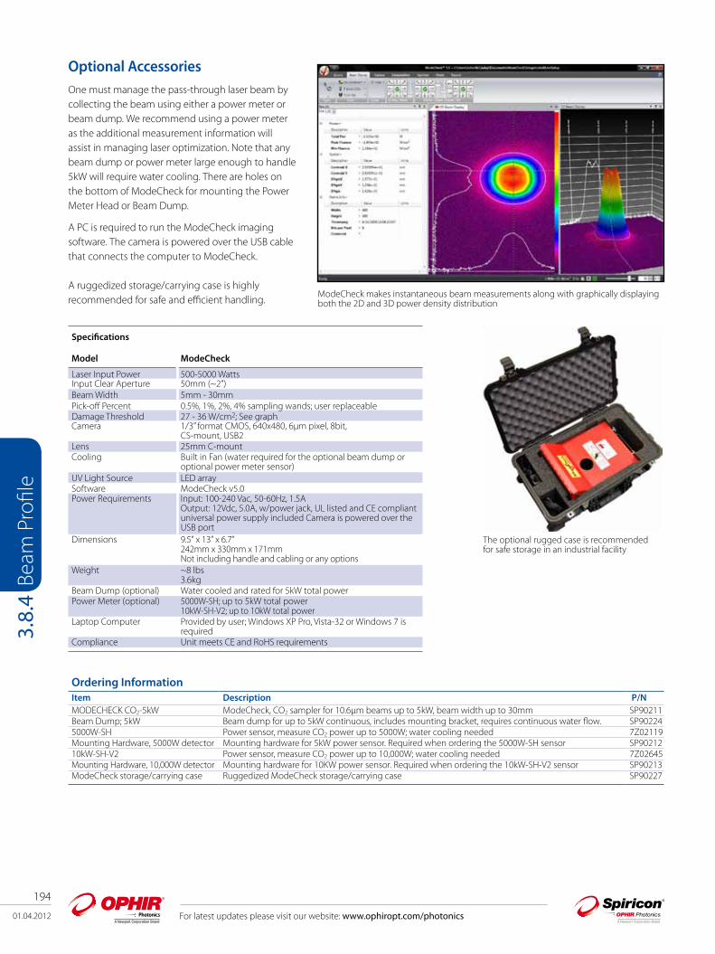
194
01.04.2012 For latest updates please visit our website: www.ophiropt.com/photonics
Beam
Pro
file
3.8.
4
Ordering Information Item Description P/N MODECHECK CO2-5kW ModeCheck, CO2 sampler for 10.6µm beams up to 5kW, beam width up to 30mm SP90211Beam Dump; 5kW Beam dump for up to 5kW continuous, includes mounting bracket, requires continuous water flow. SP902245000W-SH Power sensor, measure CO2 power up to 5000W; water cooling needed 7Z02119Mounting Hardware, 5000W detector Mounting hardware for 5kW power sensor. Required when ordering the 5000W-SH sensor SP9021210kW-SH-V2 Power sensor, measure CO2 power up to 10,000W; water cooling needed 7Z02645Mounting Hardware, 10,000W detector Mounting hardware for 10KW power sensor. Required when ordering the 10kW-SH-V2 sensor SP90213ModeCheck storage/carrying case Ruggedized ModeCheck storage/carrying case SP90227
Optional AccessoriesOne must manage the pass-through laser beam by collecting the beam using either a power meter or beam dump. We recommend using a power meter as the additional measurement information will assist in managing laser optimization. Note that any beam dump or power meter large enough to handle 5kW will require water cooling. There are holes on the bottom of ModeCheck for mounting the Power Meter Head or Beam Dump.
A PC is required to run the ModeCheck imaging software. The camera is powered over the USB cable that connects the computer to ModeCheck.
A ruggedized storage/carrying case is highly recommended for safe and efficient handling.
The optional rugged case is recommended for safe storage in an industrial facility
ModeCheck makes instantaneous beam measurements along with graphically displaying both the 2D and 3D power density distribution
Specifications
Model ModeCheck
Laser Input Power 500-5000 WattsInput Clear Aperture 50mm (~2”)Beam Width 5mm - 30mmPick-off Percent 0.5%, 1%, 2%, 4% sampling wands; user replaceableDamage Threshold 27 - 36 W/cm2; See graphCamera 1/3” format CMOS, 640x480, 6µm pixel, 8bit,
CS-mount, USB2Lens 25mm C-mountCooling Built in Fan (water required for the optional beam dump or
optional power meter sensor)UV Light Source LED arraySoftware ModeCheck v5.0Power Requirements Input: 100-240 Vac, 50-60Hz, 1.5A
Output: 12Vdc, 5.0A, w/power jack, UL listed and CE compliant universal power supply included Camera is powered over the USB port
Dimensions 9.5” x 13” x 6.7”242mm x 330mm x 171mmNot including handle and cabling or any options
Weight ~8 lbs3.6kg
Beam Dump (optional) Water cooled and rated for 5kW total powerPower Meter (optional) 5000W-SH; up to 5kW total power
10kW-SH-V2; up to 10kW total powerLaptop Computer Provided by user; Windows XP Pro, Vista-32 or Windows 7 is
requiredCompliance Unit meets CE and RoHS requirements

01.04.2012
195
For latest updates please visit our website: www.ophiropt.com/photonics
Beam
Pro
file
3.8.
5.1
3.8.5 High Power - In-Line Industrial Beam Monitoring
3.8.5.1 II-VI-CO2 Series An in-line industrial laser beam monitoring solution Rapidly tune lasers for best performance for each job Monitor fluctuations while processing Optimize beams in real-time Diagnose faults quickly
The II-VI-CO2-BS-35 Profiler Beam Sampler was developed by II-VI, a leading industrial optics supplier, specifically to enable measurement and viewing of high power industrial CO2 beams. Spiricon and II-VI have teamed up to provide solutions to vexing laser beam stability, alignment, tuning, and optimizing difficulties.
The II-VI-CO2-58 series Profiler consists of a set of turning mirrors that direct the beam to a sampling beam splitter, and then returns it to the original in-line path. After passing through the splitter, the sampled beam passes through additional attenuation and a beam telescope to size the beam for a Pyrocam III infrared camera. The camera is connected to a PC computer through a Firewire interface. A Basic Image Viewer presents 3D isometric plots, 2D color contour plots and grayscale, among other views. Add BGS-PC-PIII beam analyzer software to access many quantitative analysis, computations and charting functions. The II-VI-CO2-58 Series Profiler is similar to the BS model but the original beam is not returned "in-line". Both a horizontal and vertical entry model are available. The Pyrocam III with BGS-PC software must be ordered separately.
Model Wavelength Power Beam Width Beam Input Cooling
II-VI-CO2-BS-35 10.6µm up to 8kW 20mm Vertical or Horizontal Requires external water II-VI-CO2-58-D8-WC-H 10.6µm up to 10kW 29mm Horizontal Requires external water II-VI-CO2-58-D8-WC-V 10.6µm up to 10kW 29mm Vertical Requires external water
II-VI-CO2-BS-35
II-VI-CO2-58-D8-WC-V Side View
II-VI-CO2-58-D8-WC-V Top View
Ordering Information Item Description P/N II-VI-CO2-BS-35 II-VI-CO2 in-line sampler, for 10.6µm beams up to 8 kW. Beam width up 20 mm. Pyrocam III Beam Profiler System
required (ordered separately). Recommended model: PY-III-C-A or PY-III-C-B with a Germanium 10.6μm window. BGS-PC-PIII laser beam analyzer software included with Pyrocam system
SP90062
II-VI-CO2-58-D8-WC-H CO2 laser beam sampler for lasers up to 10kW. Input Clear Aperture is 58mm. Requires cooling water. Horizontal entry. Built-in 8X beam reducer and adapters for Pyrocam III. Order Pyrocam III separately. BGS-PC-PIII laser beam analyzer software included with Pyrocam system
SP90160
II-VI-CO2-58-D8-WC-V Same as above but with Vertical Entry SP90161
II-VI-CO2-58

196
01.04.2012 For latest updates please visit our website: www.ophiropt.com/photonics
Beam
Pro
file
3.9
3.9 Goniometric RadiometersLD 8900, LD 8900R Far-Field ProfilersProfiling divergent light sources presents many challenges, but Photon’s far-field profilers characterize the angular radiation intensity of light simply and accurately in real time. Both the LD 8900 and LD 8900R (wide dynamic range Goniometric Radiometer) provide full 3-dimensional measurements of the far-field pattern in minutes or less, with far better resolution than a CCD camera. The LD 8900 far-field profiler provides direct real-time far-field measurements with >24dB dynamic range, while the wide dynamic range LD 8900R has a dynamic range of >36dB, which provides greater detail in the “tails” of the far-field pattern. Both models have an angular sampling resolution of 0.055º and a field-of-view of ±72° (144°), and are ideal for characterizing the light flux from many sources, including VCSELs, laser diodes (LDs), optical fibers, optical waveguides, and more. With the LD 8900R, measurement of the mode field diameter of optical fiber is possible in real time with greater than 5% accuracy. The LD 8900 and the LD 8900R are available with either a silicon or InGaAs detector and have a standard entrance aperture of 2mm, with an optional 10mm entrance aperture for use with larger sources such as LEDs and LD bars.
LD 8900 and LD 8900R complete systems include:
The Scan Unit The Motion Control Module Goniometric Radiometer Acquisition and Analysis Software for Microsoft Windows operating systems PCI Interface Box Power and instrument cables An optional semi-custom source mount, specifically designed to meet your application needs, can be quoted upon request for either the LD 8900 or the LD 8900R
Mode Field Diameter in Real Time with LD 8900R
The LD 8900R allows for real-time measurements of Mode Field Diameter (MFD) with an accuracy of ±5%* for a nominal 10µm single-mode fiber. Mode Field Diameter (MFD) of single-mode optical fiber is measured using the methodology described in the Telecommunication Industry Association/ Electronic Industries Association (TIA/EIA) Standard FOTP-191. Specifically, the MFD is calculated using the Petermann II integral, with data sampled at angular resolution of 0.055° and collected over an angular extent of ±72° (144° viewing angle). *If greater accuracy is required, Photon’s LD 8900HDR is specifically designed to measure MFD and A
eff to greater than 0.5%
Polar View (left); 3D View (top); Beam Statistics (bottom) with LD 8900R
Topographical View - LD 8900R Laser Diode Diffraction Rings
Windows Showing Unifomity of a Laser Diode

01.04.2012
197
For latest updates please visit our website: www.ophiropt.com/photonics
Beam
Pro
file
3.9
LD 8900/LD 8900R System SpecificationsSensor/Detector
Scan Radius 84mmPinhole Size 1000µm (options available)Entrance Aperture 2mm standard (optional 1cm)Field of View ±72° (144 degrees)Azimuthal Scans 1, 2, 10, 20, 50, 100, or 200Spatial Sampling Resolution 0.055 degrees, 3241points/scan
Spectral RangeSilicon detector 320-1100nmInGaAs detector 800-1700nmOptional UV 190-~1100nm
Source Input Power for >400nmMirror Damage Threshold CW 900 W/cm²Mirror Damage Threshold Pulsed 1 J/cm²LDs, multi-mode fiber w/ NA >0.5 10’s of µW to 10’s of W*Single-mode fiber 1µW to 1W**For wavelengths <400nm Contact PhotonHigher power options available Contact PhotonSource Output CW or Pulsed (rep rates >10kHz)
Parameters Measured Angular Widths FWHM, 5%, 13.5%, 2 user-specified clip levelsNumerical Apertures FWHM, 5%, 13.5%, 2 user-specified clip levels Angular Width Ratios FWHM, 5%, 13.5%, 2 user-specified clip levelsAngular Position Centroid, Peak Intensity or Amplitude Centroid, Peak, 2 user-specified locationsMode-Field Diameter LD 8900R onlyRelative Integrated Power Relative Power in user-specified cone angles about an arbitrary axis
Data Update RatesSingle scan updates: ~ 5HzPerpendicular Scan updates ~ 0.5Hz3D Profile Acquisition Time* * Times are PC dependent10 azimuthal scans ~7s20 azimuthal scans ~14s 50 azimuthal scans ~35s 100 azimuthal scans ~70s200 azimuthal scans ~140s
File Saving and Data LoggingProgram Data and Setup Configuration FilesASCII file Profiles and Summary ParametersRaw 3D Scan Data in binary formatScreen Captures: BMP, JPG, GIF, TIFF, PNGLog to Files and COM Ports
CommunicationsRS-232 Serial COM port required ActiveX Automation
Electrical/MechanicalAC Power Required 110V ~ 60Hz standard, 220V ~ 50Hz optional (Installation Category: Class II)Main supply voltage fluctuations: Not to exceed ±10% of the nominal voltage; Transient overvoltage according to Installation Category II;
Pollution Degree 1 or 2 in accordance with IEC 664.Dimensions mm
Scanning Unit 318 × 228 × 241Scanner 203 × 165 × 165Motion Controller 51 × 89 × 248
Environmental ConditionsIndoor use
Temperature 5°C – 40°CAltitude Up to 2000mMaximum relative humidity 80% for temperature up to 31°C decreasing linearly to 50% relative humidity at 40°C

198
01.04.2012 For latest updates please visit our website: www.ophiropt.com/photonics
Beam
Pro
file
3.9
Item Description P/N
LD8900/InGaAs Goniometric Radiometer for characterizing the angular radiation intensity from a laser diode between 800nm and 1700nm wavelength. Entrance aperture 2mm.
PH00173
LD8900/Si Goniometric Radiometer for characterizing the angular radiation intensity from a laser diode between 320nm and 1100nm wavelength. Entrance aperture 2mm. Full 3D capability. Features dynamic range >36dB with 0 dB source.
PH00174
LD8900R/InGaAs Wide Dynamic Range Goniometric Radiometer for characterizing the angular radiation irradiance from a fiber optic, wave guide, laser diode, VCSEL, or LED between 800nm and 1700nm wavelength.
PH00175
LD8900R/Si Wide Dynamic Range Goniometric Radiometer for characterizing the angular radiation irradiance from a fiber optic, waveguide, laser diode, VCSEL or LED between 320nm and 1100nm wavelength. Full 3D capability.
PH00176
OptionsWL-O Wavelength option PH00183Pulsed InGaAs Pulsed Option
Failsafe operation for pulsed sources operating at repetition rates >10kHz with pulse widths >500ns. For operation below 10kHz, there are possible gain saturation states, dependent on repetition rate, pulse width, and source power. Consult the factory when operating under these conditions for failure mode assessment. When questionable, pulsed source operation should be verified against CW operation.
PH00185
Pulsed Upgrade InGaAs Pulsed Upgrade Option
Pulsed Upgrade Option to an existing Goniometric Radiometer InGaAs system. Failsafe operation for pulsed sources operating at repetition rates >10kHz with pulse widths >500ns. For operation below 10kHz, there are possible gain saturation states, dependent on repetition rate, pulse width, and source power. Consult the factory when operating under these conditions for failure mode assessment. When questionable, pulse source operation should be verified against CW operation. Includes software upgrade. Contact Factory for details.
PH00186
PCI Controller Upgrade Interface to allow use with standard PCI interface of desktop PC. Includes an interface box for 9180 controller card, PCI Interface card and cable, and factory calibration and realignment. System should be returned to Photon for installation. Includes software upgrade.
PH00187
Optional Mount of User Device -LD 8900 Mount
Photon will provide one semi-custom mount of customer’s laser diode device. Submit device particulars for specific quote. With this option, the instrument can be used immediately and provides one example test fixture.
PH00181
Software Viewer Goniometric Radiometer Software Viewer allows users to open, review and re-analyze files that are saved, using any computer. The Viewer has all the data processing features of the software. You can read files saved with the same version and some earlier versions of the software. Available for MS Windows current software.
PH00182
Fiber Mount - /FC Plate and mount for a single mode fiber with FC connector. Label on plate includes reference distance between source and datum plane.
PH00189
Fiber Mount - /SC Plate and mount for a single mode fiber with SC connector. Label on plate includes reference distance between source and datum plane.
PH00190
Fiber Mount - /ST Plate and mount for a single mode fiber with ST connector. Label on plate includes reference distance between source and datum plane.
PH00191
Fiber Mount -/BF Plate and mount for a single mode fiber without connector. Label on plate includes reference distance between source and datum plane.
PH00192
Option to Fiber Mount /BF - /Ribbon
Optional 4-Fiber Ribbon Cartridge for the Fiber Mount /BF (Bare Fiber). Requires /BF. PH00193
Extended Cable Option - EXT Cable
Cable lengths extended. PH00184
NIST Reference Standard N.A. Reference Standard: traceable to NIST for use with Goniometric Radiometer/Far-Field profilers; i.e. LD8900 and/or LD8900R. Data provided: N.A. and Angular Widths at 50%, 13.5% and 5% clip levels, with standard deviation [with a recorded, exact source to aperture distance]. NIST reference standard includes: LD source Single Mode Test Fiber Required Mounting Plate in a storage case.
PH00188
Ordering Information - Goniometric Radiometer Far-Field Profilers
All Goniometric Radiometer LD 8900 Far-Field Profiler Systems include the Scan Unit, PCI Controller Interface, Current MS Windows software, including ActiveX Automation commands. All LD 8900R systems include the above as well as a dynamic range >36dB with 0dB source. System incorporates 16-bit digitizer, light scatter control and special amplifiers to achieve higher dynamic range than standard LD8900. For pulsed operation, please consult the factory.

01.04.2012
199
For latest updates please visit our website: www.ophiropt.com/photonics
Beam
Pro
file
3.9
LD 8900HDR Far-Field ProfilerThe photonics community needs a method for very high dynamic range measurements of optical fiber, waveguide and other optical components. Advances in DWDM technology, deployment of standard fibers, and the development of specialty fibers all require more accurate characterization. These high-dynamic-range measurements of irradiant light flux have been very difficult to obtain. Photon has the solution: our Goniometric Radiometer, the LD 8900HDR Far-Field Profiler.
Measurement Parameters
The LD 8900HDR Far-Field Profiler uses goniometric methodology to measure true 3- dimensional profiles of optical components with up to 93 dB dynamic range. All measurements are taken with the emitting fiber, planar waveguide, laser diode or LED inserted directly into the center of the instrument’s radial measurement area. For optical fiber, the far-field distribution pattern is acquired without bending the fiber. Bending the fiber can cause analysis and reporting inaccuracies. Parameters measured for optical fiber are:
Mode Field Diameter (MFD) – used to evaluate losses due to mismatch at connections of fibers and fiber components. Effective Area (Aeff ) – used to assess non-linear effects Numerical Aperture (NA) – a measure of the angular width of the fiber output. NA is equal to the sine of the half angle (sin θ/2) at a specified percentage of the peak value.
The Model LD 8900HDR analysis software calculates these optical fiber parameters from the far-field profile, the method described in the TIA/EIA FOTP-191 standard for MFD requiring a minimum of 50dB for proper measurement. The TIA/EIA FOTP-132 standard for A requires a minimum of 50dB for proper measurements as well.
This wider dynamic range provides greater signal-to-noise detail in the tails of the far-field pattern. Real-time data gathering and reporting of sample optical fibers or other sources is valuable for manufacturing and quality assurance evaluation.
Hardware and Computer
The LD 8900HDR is a modular system that allows either one-dimensional or three-dimensional measurements. The 3D module is easily exchanged with the 1D hardware, and the system can be purchased with the 1D hardware, the 3D hardware or both. There are specially designed fiber mounting clips available for both the 1D and 3D configurations with a specially modified fiber cleaver and clip that guarantees proper fiber alignment. In addition, custom mounting devices are available for high dynamic range measurements of waveguides, laser diodes and LEDs.
The controller comprises the PC microprocessor, data acquisition card, scan-control card and LD 8900HDR acquisition and analysis software. A reference calibration standard (NIST traceable), 1310nm, 0dBm LD Light Source is also available. This is the measured reference at the time of original manufacture that can be used for unit verification by the user at a later date. For high dynamic range measurements in the visible spectrum, a silicon detector can be substituted with a spectral range of 320-1100nm and even higher 103dB dynamic range. Maximum light source unit size for direct measurements is approximately 12.7mm by 12.7mm.
In the 3D configuration the LD 8900HDR includes the 3D Motion Control Module and is capable of full 3D measurements with up to 200 azimuthal planes through the source.
3D profile of a SMF-28 optical fiber using the LD 8900HDR
3D polar view of LED light emission LD 8900 HDR
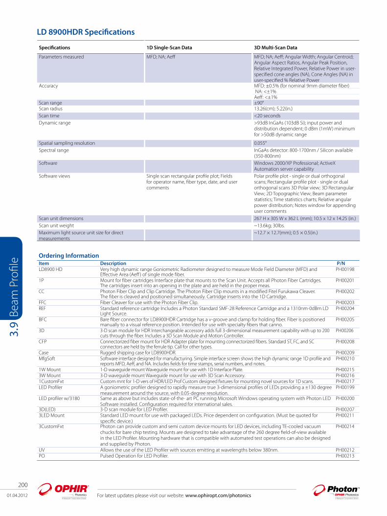
200
01.04.2012 For latest updates please visit our website: www.ophiropt.com/photonics
Beam
Pro
file
3.9
Specifications 1D Single-Scan Data 3D Multi-Scan Data
Parameters measured MFD; NA; Aeff MFD; NA; Aeff; Angular Width; Angular Centroid; Angular Aspect Ratios, Angular Peak Position, Relative Integrated Power, Relative Power in user-specified cone angles (NA), Cone Angles (NA) in user-specified % Relative Power
Accuracy MFD: ±0.5% (for nominal 9mm diameter fiber) NA: <±1% Aeff: <±1%
Scan range ±90°Scan radius 13.26(cm); 5.22(in.)Scan time <20 secondsDynamic range >93dB InGaAs (103dB Si); input power and
distribution dependent; 0 dBm (1mW) minimum for >50dB dynamic range
Spatial sampling resolution 0.055°Spectral range InGaAs detector: 800-1700nm / Silicon available
(350-800nm)Software Windows 2000/XP Professional; ActiveX
Automation server capabilitySoftware views Single scan rectangular profile plot; Fields
for operator name, fiber type, date, and user comments
Polar profile plot - single or dual orthogonal scans; Rectangular profile plot - single or dual orthogonal scans 3D Polar view; 3D Rectangular View; 2D Topographic View; Beam parameter statistics; Time statistics charts; Relative angular power distribution; Notes window for appending user comments
Scan unit dimensions 267 H x 305 W x 362 L (mm); 10.5 x 12 x 14.25 (in.)Scan unit weight ~13.6kg; 30lbs.Maximum light source unit size for direct measurements
~12.7 × 12.7(mm); 0.5 × 0.5(in.)
LD 8900HDR Specifications
Ordering InformationItem Description P/N LD8900 HD Very high dynamic range Goniometric Radiometer designed to measure Mode Field Diameter (MFD) and
Effective Area (Aeff ) of single mode fiber.PH00198
1P Mount for fiber cartridges Interface plate that mounts to the Scan Unit. Accepts all Photon Fiber Cartridges. The cartridges insert into an opening in the plate and are held in the proper meas.
PH00201
CC Photon Fiber Clip and Clip Cartridge. The Photon Fiber Clip mounts in a modified Fitel Furukawa Cleaver. The fiber is cleaved and positioned simultaneously. Cartridge inserts into the 1D Cartridge.
PH00202
FFC Fiber Cleaver for use with the Photon Fiber Clip. PH00203REF Standard reference cartridge Includes a Photon Standard SMF-28 Reference Cartridge and a 1310nm-0dBm LD
Light Source.PH00204
BFC Bare fiber connector for LD8900HDR Cartridge has a v-groove and clamp for holding fiber. Fiber is positioned manually to a visual reference position. Intended for use with specialty fibers that canno.
PH00205
3D 3-D scan module for HDR Interchangeable accessory adds full 3-dimensional measurement capability with up to 200 cuts through the fiber. Includes a 3D Scan Module and Motion Controller.
PH00206
CFP Connectorized fiber mount for HDR Adapter plate for mounting connectorized fibers. Standard ST, FC, and SC connectors are held by the ferrule tip. Call for other types.
PH00208
Case Rugged shipping case for LD8900HDR. PH00209MfgSoft Software interface designed for manufacturing. Simple interface screen shows the high dynamic range 1D profile and
reports MFD, Aeff, and NA. Includes fields for time stamps, serial numbers, and notes.PH00210
1W Mount 1-D waveguide mount Waveguide mount for use with 1D Interface Plate. PH002153W Mount 3-D waveguide mount Waveguide mount for use with 3D Scan Accessory. PH002161CustomFxt Custom mnt for 1-D vers of HDR/LED Prof Custom designed fixtures for mounting novel sources for 1D scans. PH00217LED Profiler A goniometric profiler designed to rapidly measure true 3-dimensional profiles of LEDs providing a ±130 degree
measurement around the source, with 0.05-degree resolution.PH00199
LED profiler w/3180 Same as above but includes state-of-the- art PC running Microsoft Windows operating system with Photon LED Software installed. Configuration required for international sales.
PH00200
3D(LED) 3-D scan module for LED Profiler. PH002073LED Mount Standard LED mount for use with packaged LEDs. Price dependent on configuration. (Must be quoted for
specific device.)PH00211
3CustomFxt Photon can provide custom and semi custom device mounts for LED devices, including TE-cooled vacuum chucks for bare chip testing. Mounts are designed to take advantage of the 260 degree field-of-view available in the LED Profiler. Mounting hardware that is compatible with automated test operations can also be designed and supplied by Photon.
PH00214
UV Allows the use of the LED Profiler with sources emitting at wavelengths below 380nm. PH00212PO Pulsed Operation for LED Profiler. PH00213
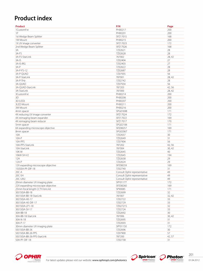
For latest updates please visit our website: www.ophiropt.com/photonics 01.04.2012
201
Product index Product P/N Page1CustomFxt PH00217 2001P PH00201 2001st Wedge Beam Splitter SPZ17015 1681W Mount PH00215 2001X UV image converter SPZ17023 1722nd Wedge Beam Splitter SPZ17026 1683A 7Z02621 283A-FS 7Z02628 283A-FS-StarLink 767002 28, 423A-IS 7Z02404 273A-IS-IRG 7Z02403 273A-P 7Z02622 283A-P-FS-12 7Z02687 283A-P-QUAD 7Z07935 563A-P-StarLink 787001 28, 423A-P-THz 7Z02742 283A-QUAD 7Z07934 563A-QUAD-StarLink 787203 42, 563A-StarLink 787000 28, 423CustomFxt PH00214 2003D PH00206 2003D (LED) PH00207 2003LED Mount PH00211 2003W Mount PH00216 2004mm spacer SPG01698 1714X reducing UV image converter SPZ17024 1724X reimaging beam expander SPZ17022 1694X reimaging beam reducer SPZ17017 1705mm spacer SPG02106 1716X expanding microscope objective SPZ08257 1698mm spacer SPG02067 17110A 7Z02637 3010A-P 7Z02649 3110A-PPS 7Z07904 5610A-PPS-StarLink 787202 42, 5610A-StarLink 787004 30, 4210K-W 7Z02645 4010kW-SH-V2 7Z02645 19412A 7Z02638 2912A-P 7Z02624 2912X expanding microscope objective SPZ08259 16915(50)A-PF-DIF-18 7Z02740 3120C-A Consult Ophir representative 4920C-SH Consult Ophir representative 4920C-UAU Consult Ophir representative 4920mm diameter UV imaging plate SPF01177 17222X expanding microscope objective SPZ08260 16925mm focal length CCTV lens kit SP90085 17130(150)A-BB-18 7Z02699 3230(150)A-BB-18-StarLink 787007 32, 4230(150)A-HE-17 7Z02722 3330(150)A-HE-DIF-17 7Z02729 3330(150)A-LP1-18 7Z02721S 3230(150)A-SV-17 7Z02724 3330A-BB-18 7Z02692 3030A-BB-18-StarLink 787006 30, 4230A-N-18 7Z02695 3130A-P-17 7Z02693 3130mm diameter UV imaging plate SPF01150 17250(150)A-BB-26 7Z02696 3050(150)A-BB-26-PPS 7Z07900 5750(150)A-BB-26-PPS-StarLink 787200 42, 5750A-PF-DIF-18 7Z02738 31
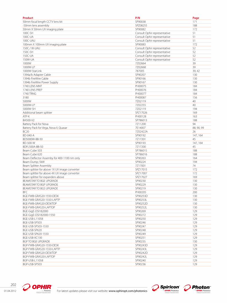
202
01.04.2012 For latest updates please visit our website: www.ophiropt.com/photonics
Product P/N Page50mm focal length CCTV lens kit SP90038 171-50mm lens assembly SPZ08255 18850mm X 50mm UV imaging plate SP90082 172100C-SH Consult Ophir representative 51100C-UA Consult Ophir representative 51100C-UAU Consult Ophir representative 51100mm X 100mm UV imaging plate SP90083 172150C / W-UAU Consult Ophir representative 52150C-SH Consult Ophir representative 52150C-UA Consult Ophir representative 52150W-UA Consult Ophir representative 521000W 7Z02664 391000W-LP 7Z02668 391000W-StarLink 787005 39, 421394a/b Adapter Cable SP90207 1301394b FireWire Cable SP90166 1301394b FireWire Power Supply SP90167 1301740 LENS MNT PH00075 1841740 LENS PREP PH00076 1841740 TRNG PH00077 1843180 PH00087 1565000W 7Z02119 405000W-LP 7Z02255 405000W-SH 7Z02119 194Additional beam splitter SPZ17026 169ATP-K PH00128 163BA500-V2 SP786013 188Battery Pack for Nova 7Z11200 94Battery Pack for Vega, Nova II, Quasar 7E14007 88, 90, 99BC20 7Z02422A 26BD-040-A SP90192 147, 164BD5000W-BB-50 7Z17201 45BD-500-W SP90193 147, 164BDFL500A-BB-50 7Z17200 45Beam Cube 503 SP786015 188Beam Cube 620 SP786016 188Beam Deflector Assemby for 400-1100 nm only SP90263 164Beam Dump; 5kW SP90224 194Beam Splitter Assembly 7Z17001 74Beam splitter for above 1X UV image converter SPZ17015 172Beam splitter for above 4X UV image converter SPZ17007 172Beam splitter for expanders above SPZ17027 169BEAMSTAR TO BGE UPGRADE SP90230 130BEAMSTAR TO BGP UPGRADE SP90229 130BEAMSTAR TO BGS UPGRADE SP90219 130BFC PH00205 200BGE-FWB-GRAS20-1550-DESK SP90253D 130BGE-FWB-GRAS20-1550-LAPTP SP90253L 130BGE-FWB-GRAS20-DESKTOP SP90252D 130BGE-FWB-GRAS20-LAPTOP SP90252L 130BGE-GigE-OSI182000 SP90269 129BGE-GigE-OSI182000-1550 SP90272 129BGE-USB-L11058 SP90250 129BGE-USB-SP503 SP90246 129BGE-USB-SP503-1550 SP90247 129BGE-USB-SP620 SP90248 129BGE-USB-SP620-1550 SP90249 129BGE-USB-XC130 SP90251 129BGP TO BGE UPGRADE SP90235 130BGP-FWB-GRAS20-1550-DESK SP90243D 129BGP-FWB-GRAS20-1550-LAPTP SP90243L 129BGP-FWB-GRAS20-DESKTOP SP90242D 129BGP-FWB-GRAS20-LAPTOP SP90242L 129BGP-USB-L11058 SP90240 129BGP-USB-SP503 SP90236 129
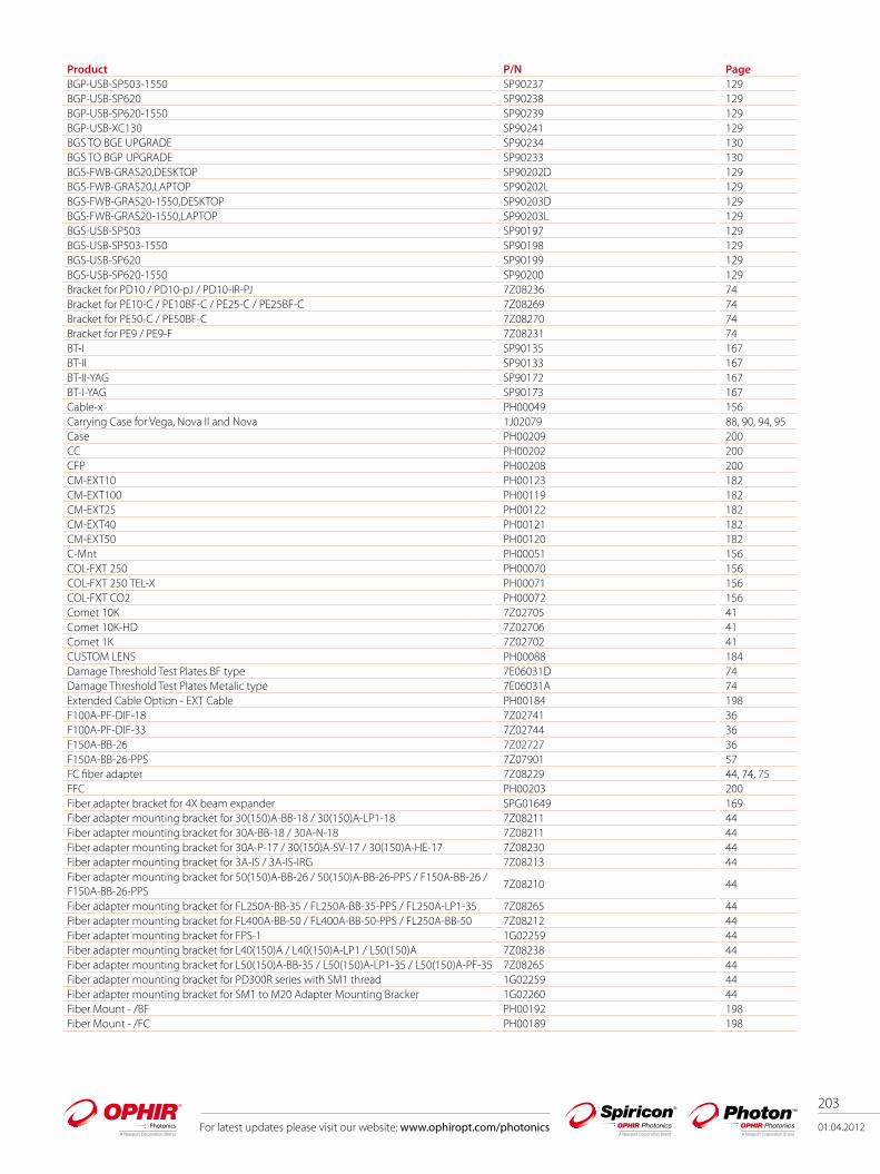
For latest updates please visit our website: www.ophiropt.com/photonics 01.04.2012
203
Product P/N PageBGP-USB-SP503-1550 SP90237 129BGP-USB-SP620 SP90238 129BGP-USB-SP620-1550 SP90239 129BGP-USB-XC130 SP90241 129BGS TO BGE UPGRADE SP90234 130BGS TO BGP UPGRADE SP90233 130BGS-FWB-GRAS20,DESKTOP SP90202D 129BGS-FWB-GRAS20,LAPTOP SP90202L 129BGS-FWB-GRAS20-1550,DESKTOP SP90203D 129BGS-FWB-GRAS20-1550,LAPTOP SP90203L 129BGS-USB-SP503 SP90197 129BGS-USB-SP503-1550 SP90198 129BGS-USB-SP620 SP90199 129BGS-USB-SP620-1550 SP90200 129Bracket for PD10 / PD10-pJ / PD10-IR-PJ 7Z08236 74Bracket for PE10-C / PE10BF-C / PE25-C / PE25BF-C 7Z08269 74Bracket for PE50-C / PE50BF-C 7Z08270 74Bracket for PE9 / PE9-F 7Z08231 74BT-I SP90135 167BT-II SP90133 167BT-II-YAG SP90172 167BT-I-YAG SP90173 167Cable-x PH00049 156Carrying Case for Vega, Nova II and Nova 1J02079 88, 90, 94, 95Case PH00209 200CC PH00202 200CFP PH00208 200CM-EXT10 PH00123 182CM-EXT100 PH00119 182CM-EXT25 PH00122 182CM-EXT40 PH00121 182CM-EXT50 PH00120 182C-Mnt PH00051 156COL-FXT 250 PH00070 156COL-FXT 250 TEL-X PH00071 156COL-FXT CO2 PH00072 156Comet 10K 7Z02705 41Comet 10K-HD 7Z02706 41Comet 1K 7Z02702 41CUSTOM LENS PH00088 184Damage Threshold Test Plates BF type 7E06031D 74Damage Threshold Test Plates Metalic type 7E06031A 74Extended Cable Option - EXT Cable PH00184 198F100A-PF-DIF-18 7Z02741 36F100A-PF-DIF-33 7Z02744 36F150A-BB-26 7Z02727 36F150A-BB-26-PPS 7Z07901 57FC fiber adapter 7Z08229 44, 74, 75 FFC PH00203 200Fiber adapter bracket for 4X beam expander SPG01649 169Fiber adapter mounting bracket for 30(150)A-BB-18 / 30(150)A-LP1-18 7Z08211 44Fiber adapter mounting bracket for 30A-BB-18 / 30A-N-18 7Z08211 44Fiber adapter mounting bracket for 30A-P-17 / 30(150)A-SV-17 / 30(150)A-HE-17 7Z08230 44Fiber adapter mounting bracket for 3A-IS / 3A-IS-IRG 7Z08213 44Fiber adapter mounting bracket for 50(150)A-BB-26 / 50(150)A-BB-26-PPS / F150A-BB-26 / F150A-BB-26-PPS
7Z08210 44
Fiber adapter mounting bracket for FL250A-BB-35 / FL250A-BB-35-PPS / FL250A-LP1-35 7Z08265 44Fiber adapter mounting bracket for FL400A-BB-50 / FL400A-BB-50-PPS / FL250A-BB-50 7Z08212 44Fiber adapter mounting bracket for FPS-1 1G02259 44Fiber adapter mounting bracket for L40(150)A / L40(150)A-LP1 / L50(150)A 7Z08238 44Fiber adapter mounting bracket for L50(150)A-BB-35 / L50(150)A-LP1-35 / L50(150)A-PF-35 7Z08265 44Fiber adapter mounting bracket for PD300R series with SM1 thread 1G02259 44Fiber adapter mounting bracket for SM1 to M20 Adapter Mounting Bracker 1G02260 44Fiber Mount - /BF PH00192 198Fiber Mount - /FC PH00189 198

204
01.04.2012 For latest updates please visit our website: www.ophiropt.com/photonics
Product P/N PageFiber Mount - /SC PH00190 198Fiber Mount - /ST PH00191 198Filter for 1300nm SPZ08242 163Filter for 355nm-V2; give an undistorted image of the 355nm light SPZ08246 163Filter holder and 50x50 filter set for 4X beam reducer SPZ08240 163, 170FL250A-BB-35 7Z02728 36FL250A-BB-50 7Z02739 37FL250A-BB-50-PPS 7Z07902 58FL250A-BB-50-PPS-StarLink 787201 42, 58FL250A-LP1-35 7Z02731S 36FL250A-LP1-DIF-33 7Z02733 36FL250A-RP 7Z02921 71FL400A-BB-50 7Z02734 37FL400A-BB-50-PPS 7Z07903 58FL400A-LP-50 7Z02735 37FL500A 7Z02648 37FL500A-LP1 7Z02667S 37FOCTUBE20-30 PH00124 182FOCTUBE30-50 PH00125 182FOCTUBE50-90 PH00126 182FPS-1 fast photodiode 7Z02505 75FSA-100Y SP90188 147FSA-125Y SP90189 147FSA-150Y SP90190 147FSA-200Y SP90191 147FSA-50Y SP90187 147Heat Sink 7Z08267 74H-I 100X PH00148 156H-I 1550 w/lens PH00081 156H-I 980-VIS w/lens PH00146 156H-I High energy IR PH00147 156H-I LA PH00082 156HP-1064 PH00134 163HP-266 PH00129 163HP-355 PH00130 163HP-450 PH00131 163HP-600 PH00132 163HP-800 PH00133 163HP-ND1 1150 thru 1600nm PH00380 156HP-ND1 350 thru 399nm PH00370 156HP-ND1 400 thru 700nm PH00371 156HP-ND1 750 thru 890nm PH00374 156HP-ND1 900 thru 1100nm PH00377 156HP-ND2 1150 thru 1600nm PH00381 156HP-ND2 400 thru 700nm PH00372 156HP-ND2 750 thru 890nm PH00375 156HP-ND2 900 thru 1100nm PH00378 156HP-ND3 1150 thru 1600nm PH00382 156HP-ND3 400 thru 700nm PH00373 156HP-ND3 750 thru 890nm PH00376 156HP-ND3 900 thru 1100nm PH00379 156II-VI-CO2-58-D8-WC-H SP90160 195II-VI-CO2-58-D8-WC-V SP90161 195II-VI-CO2-BS-35 SP90062 195IR Phosphor Card 7F01235A 44, 74Juno 7Z01250 85, 97Juno USB cable 7E01217 97L1500W 7Z02661 39L1500W-LP 7Z02665 39L1500W-LP1-RP 7Z02919 71L150C-UA Consult Ophir representative 53L150C-UAU Consult Ophir representative 53L250W 7Z02688 38L250W-UA Consult Ophir representative 53L250W-UAU Consult Ophir representative 53

For latest updates please visit our website: www.ophiropt.com/photonics 01.04.2012
205
Product P/N PageL300W-LP 7Z02689 38L300W-UA Consult Ophir representative 53L300W-UAU Consult Ophir representative 53L30A-10MM 7Z02273 30L30C-SH Consult Ophir representative 50L30C-UA Consult Ophir representative 50L30C-UAU Consult Ophir representative 50L40(150)A 7Z02626 34L40(150)A-EX 7Z02614 34L40(150)A-LP1 7Z02685S 34L50(150)A 7Z02633 34L50(150)A-BB-35 7Z02730 32L50(150)A-LP1-35 7Z02726S 32L50(150)A-PF-35 7Z02737 32L50(150)A-StarLink 787003 34, 42L50(300)A 7Z02658 35L50(300)A-IPL 7Z02651 35L50(300)A-LP1 7Z02641S 35L50(300)A-PF-65 7Z02743 35Large aperture 1st Wedge Beam Splitter SPZ17025 168Large C-mount wedge splitter SP90273 164Laserstar Battery Pack 7Z14006A 92LaserStar Dual Channel 7Z01601 84, 92Laserstar IEEE Option 78300 92, 95LaserStar Single Channle 7Z01600 84, 92LBA TO BGE UPGRADE SP90232 130LBA TO BGP UPGRADE SP90231 130LBA TO BGS UPGRADE SP90210 130LBF-50 filter set SP90081 163LBS-100 SP90061 165LBS-100 IR 0.5 SP90058 165LBS-100 IR 5.0 SP90059 165LBS-100 to 4X beam reducer adapter SPZ17029 165, 170LBS-100 YAG SP90057 165LBS-300-BB SP90186 164LBS-300-NIR SP90185 147, 164LBS-300-UV SP90183 164LBS-300-VIS SP90184 164LD8900 HD PH00198 200LD8900/InGaAs PH00173 198LD8900/Si PH00174 198LD8900R/InGaAs PH00175 198LD8900R/Si PH00176 198LED Profiler PH00199 200LED profiler w/3180 PH00200 200LENS 100 LIR PH00095 184LENS 100 NIR PH00094 184LENS 100 VIS PH00093 184LENS 190 10.6 PH00092 184LENS 200 UV-XXX PH00090 184Lens 200mm LIR PH00241 184Lens 200mm NIR PH00239 184Lens 200mm VIS PH00237 184Lens 400 2um PH00224 184LENS 400 UV-XXX PH00091 184lens 400mm LIR PH00242 184Lens 400mm NIR PH00240 184Lens 400mm VIS PH00238 184LPK-CO2-16-0.5 SP90077 192LPK-CO2-16-5.0 SP90078 192LPK-CO2-6.4-0.5 SP90075 192LPK-CO2-6.4-5.0 SP90076 192LPK-YAG-16-USB SP90170 191LPK-YAG-2.5-USB SP90168 191LPK-YAG-7-USB SP90169 191
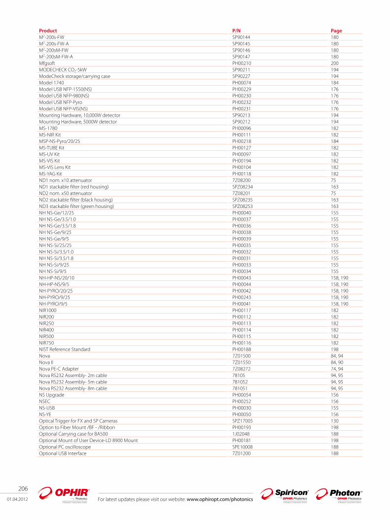
206
01.04.2012 For latest updates please visit our website: www.ophiropt.com/photonics
Product P/N PageM2-200s-FW SP90144 180M2-200s-FW-A SP90145 180M2-200sM-FW SP90146 180M2-200sM-FW-A SP90147 180Mfgsoft PH00210 200MODECHECK CO2-5kW SP90211 194ModeCheck storage/carrying case SP90227 194Model 1740 PH00074 184Model USB NFP-1550(NS) PH00229 176Model USB NFP-980(NS) PH00230 176Model USB NFP-Pyro PH00232 176Model USB NFP-VIS(NS) PH00231 176Mounting Hardware, 10,000W detector SP90213 194Mounting Hardware, 5000W detector SP90212 194MS-1780 PH00096 182MS-NIR Kit PH00111 182MSP-NS-Pyro/20/25 PH00218 184MS-TUBE Kit PH00127 182MS-UV Kit PH00097 182MS-VIS Kit PH00194 182MS-VIS Lens Kit PH00104 182MS-YAG Kit PH00118 182ND1 nom. x10 attenuator 7Z08200 75ND1 stackable filter (red housing) SPZ08234 163ND2 nom. x50 attenuator 7Z08201 75ND2 stackable filter (black housing) SPZ08235 163ND3 stackable filter (green housing) SPZ08253 163NH NS-Ge/12/25 PH00040 155NH NS-Ge/3.5/1.0 PH00037 155NH NS-Ge/3.5/1.8 PH00036 155NH NS-Ge/9/25 PH00038 155NH NS-Ge/9/5 PH00039 155NH NS-Si/25/25 PH00035 155NH NS-Si/3.5/1.0 PH00032 155NH NS-Si/3.5/1.8 PH00031 155NH NS-Si/9/25 PH00033 155NH NS-Si/9/5 PH00034 155NH-HP-NS/20/10 PH00043 158, 190NH-HP-NS/9/5 PH00044 158, 190NH-PYRO/20/25 PH00042 158, 190NH-PYRO/9/25 PH00243 158, 190NH-PYRO/9/5 PH00041 158, 190NIR1000 PH00117 182NIR200 PH00112 182NIR250 PH00113 182NIR400 PH00114 182NIR500 PH00115 182NIR750 PH00116 182NIST Reference Standard PH00188 198Nova 7Z01500 84, 94Nova II 7Z01550 84, 90Nova PE-C Adapter 7Z08272 74, 94Nova RS232 Assembly- 2m cable 78105 94, 95Nova RS232 Assembly- 5m cable 781052 94, 95Nova RS232 Assembly- 8m cable 781051 94, 95NS Upgrade PH00054 156NSEC PH00252 156NS-USB PH00030 155NS-YE PH00050 156Optical Trigger for FX and SP Cameras SPZ17005 130Option to Fiber Mount /BF - /Ribbon PH00193 198Optional Carrying case for BA500 1J02048 188Optional Mount of User Device-LD 8900 Mount PH00181 198Optional PC oscilloscope SPE10008 188Optional USB Interface 7Z01200 188
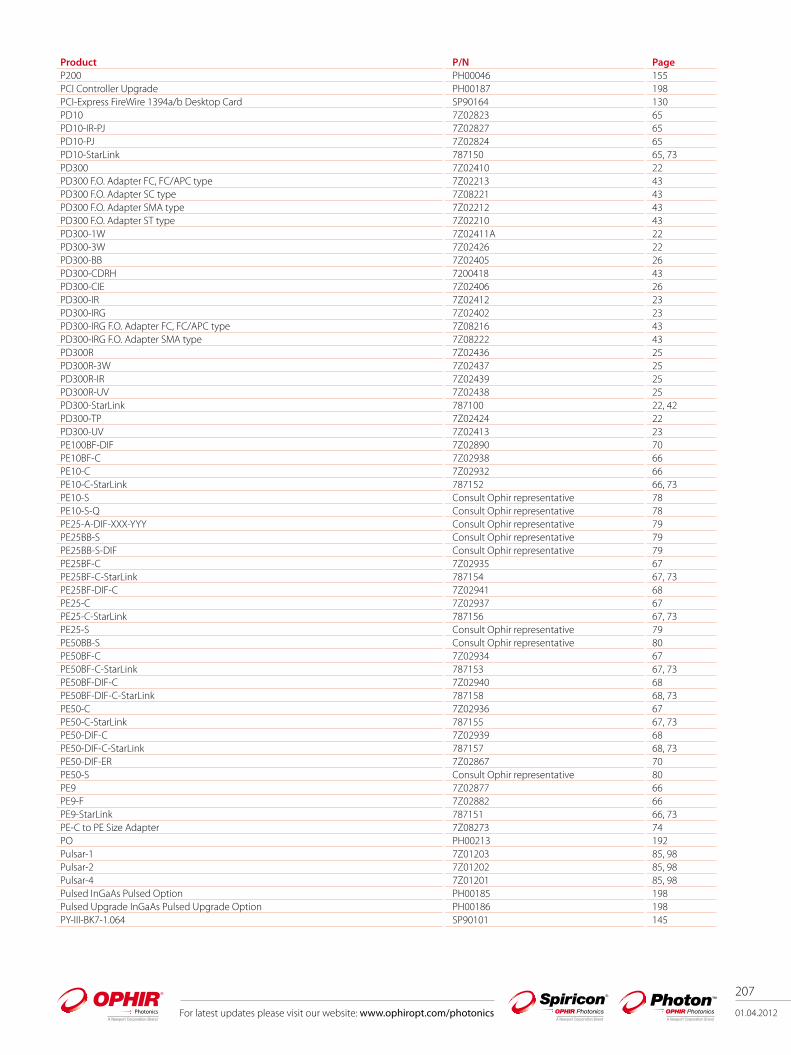
For latest updates please visit our website: www.ophiropt.com/photonics 01.04.2012
207
Product P/N PageP200 PH00046 155PCI Controller Upgrade PH00187 198PCI-Express FireWire 1394a/b Desktop Card SP90164 130PD10 7Z02823 65PD10-IR-PJ 7Z02827 65PD10-PJ 7Z02824 65PD10-StarLink 787150 65, 73PD300 7Z02410 22PD300 F.O. Adapter FC, FC/APC type 7Z02213 43PD300 F.O. Adapter SC type 7Z08221 43PD300 F.O. Adapter SMA type 7Z02212 43PD300 F.O. Adapter ST type 7Z02210 43PD300-1W 7Z02411A 22PD300-3W 7Z02426 22PD300-BB 7Z02405 26PD300-CDRH 7200418 43PD300-CIE 7Z02406 26PD300-IR 7Z02412 23PD300-IRG 7Z02402 23PD300-IRG F.O. Adapter FC, FC/APC type 7Z08216 43PD300-IRG F.O. Adapter SMA type 7Z08222 43PD300R 7Z02436 25PD300R-3W 7Z02437 25PD300R-IR 7Z02439 25PD300R-UV 7Z02438 25PD300-StarLink 787100 22, 42PD300-TP 7Z02424 22PD300-UV 7Z02413 23PE100BF-DIF 7Z02890 70PE10BF-C 7Z02938 66PE10-C 7Z02932 66PE10-C-StarLink 787152 66, 73PE10-S Consult Ophir representative 78PE10-S-Q Consult Ophir representative 78PE25-A-DIF-XXX-YYY Consult Ophir representative 79PE25BB-S Consult Ophir representative 79PE25BB-S-DIF Consult Ophir representative 79PE25BF-C 7Z02935 67PE25BF-C-StarLink 787154 67, 73PE25BF-DIF-C 7Z02941 68PE25-C 7Z02937 67PE25-C-StarLink 787156 67, 73PE25-S Consult Ophir representative 79PE50BB-S Consult Ophir representative 80PE50BF-C 7Z02934 67PE50BF-C-StarLink 787153 67, 73PE50BF-DIF-C 7Z02940 68PE50BF-DIF-C-StarLink 787158 68, 73PE50-C 7Z02936 67PE50-C-StarLink 787155 67, 73PE50-DIF-C 7Z02939 68PE50-DIF-C-StarLink 787157 68, 73PE50-DIF-ER 7Z02867 70PE50-S Consult Ophir representative 80PE9 7Z02877 66PE9-F 7Z02882 66PE9-StarLink 787151 66, 73PE-C to PE Size Adapter 7Z08273 74PO PH00213 192Pulsar-1 7Z01203 85, 98Pulsar-2 7Z01202 85, 98Pulsar-4 7Z01201 85, 98Pulsed InGaAs Pulsed Option PH00185 198Pulsed Upgrade InGaAs Pulsed Upgrade Option PH00186 198PY-III-BK7-1.064 SP90101 145
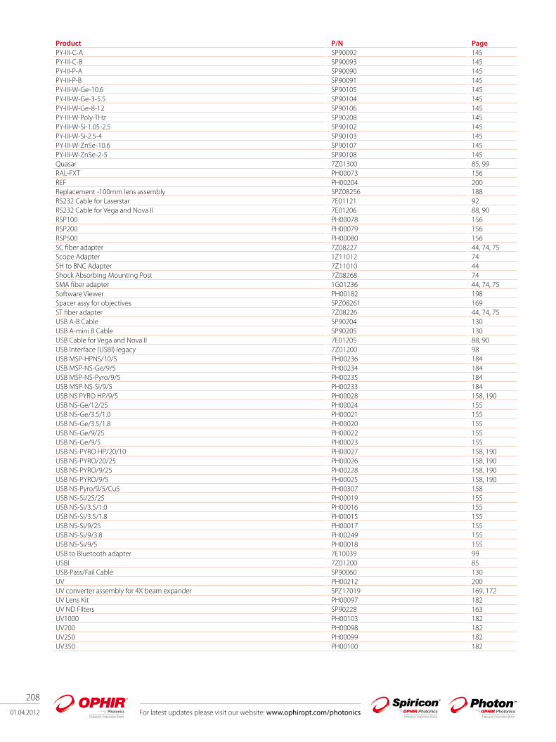
208
01.04.2012 For latest updates please visit our website: www.ophiropt.com/photonics
Product P/N PagePY-III-C-A SP90092 145PY-III-C-B SP90093 145PY-III-P-A SP90090 145PY-III-P-B SP90091 145PY-III-W-Ge-10.6 SP90105 145PY-III-W-Ge-3-5.5 SP90104 145PY-III-W-Ge-8-12 SP90106 145PY-III-W-Poly-THz SP90208 145PY-III-W-Si-1.05-2.5 SP90102 145PY-III-W-Si-2.5-4 SP90103 145PY-III-W-ZnSe-10.6 SP90107 145PY-III-W-ZnSe-2-5 SP90108 145Quasar 7Z01300 85, 99RAL-FXT PH00073 156REF PH00204 200Replacement -100mm lens assembly SPZ08256 188RS232 Cable for Laserstar 7E01121 92RS232 Cable for Vega and Nova II 7E01206 88, 90RSP100 PH00078 156RSP200 PH00079 156RSP500 PH00080 156SC fiber adapter 7Z08227 44, 74, 75 Scope Adapter 1Z11012 74SH to BNC Adapter 7Z11010 44Shock Absorbing Mounting Post 7Z08268 74SMA fiber adapter 1G01236 44, 74, 75 Software Viewer PH00182 198Spacer assy for objectives SPZ08261 169ST fiber adapter 7Z08226 44, 74, 75 USB A-B Cable SP90204 130USB A-mini B Cable SP90205 130USB Cable for Vega and Nova II 7E01205 88, 90 USB Interface (USBI) legacy 7Z01200 98USB MSP-HPNS/10/5 PH00236 184USB MSP-NS-Ge/9/5 PH00234 184USB MSP-NS-Pyro/9/5 PH00235 184USB MSP-NS-Si/9/5 PH00233 184USB NS PYRO HP/9/5 PH00028 158, 190USB NS-Ge/12/25 PH00024 155USB NS-Ge/3.5/1.0 PH00021 155USB NS-Ge/3.5/1.8 PH00020 155USB NS-Ge/9/25 PH00022 155USB NS-Ge/9/5 PH00023 155USB NS-PYRO HP/20/10 PH00027 158, 190USB NS-PYRO/20/25 PH00026 158, 190USB NS-PYRO/9/25 PH00228 158, 190USB NS-PYRO/9/5 PH00025 158, 190USB NS-Pyro/9/5/Cu5 PH00307 158USB NS-Si/25/25 PH00019 155USB NS-Si/3.5/1.0 PH00016 155USB NS-Si/3.5/1.8 PH00015 155USB NS-Si/9/25 PH00017 155USB NS-Si/9/3.8 PH00249 155USB NS-Si/9/5 PH00018 155USB to Bluetooth adapter 7E10039 99USBI 7Z01200 85USB-Pass/Fail Cable SP90060 130UV PH00212 200UV converter assembly for 4X beam expander SPZ17019 169, 172UV Lens Kit PH00097 182UV ND Filters SP90228 163UV1000 PH00103 182UV200 PH00098 182UV250 PH00099 182UV350 PH00100 182

For latest updates please visit our website: www.ophiropt.com/photonics 01.04.2012
209
Product P/N PageUV500 PH00101 182UV750 PH00102 182UView PH00226 173Variable filter SPZ17012 163Vega 7Z01560 84, 88VIS1000 PH00110 182VIS200 PH00105 182VIS250 PH00106 182VIS400 PH00107 182VIS500 PH00108 182VIS750 PH00109 182WL-O PH00183 198WVF-300 SP90195 147, 164
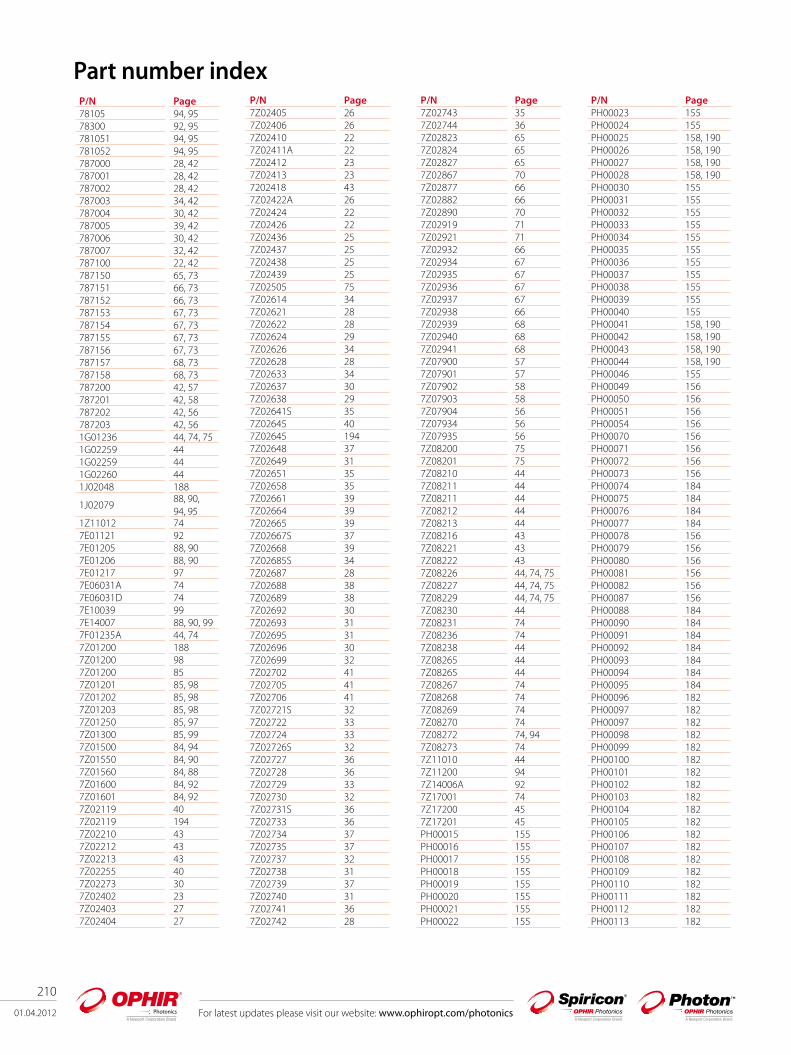
210
01.04.2012 For latest updates please visit our website: www.ophiropt.com/photonics
P/N Page78105 94, 9578300 92, 95781051 94, 95781052 94, 95787000 28, 42787001 28, 42787002 28, 42787003 34, 42787004 30, 42787005 39, 42787006 30, 42787007 32, 42787100 22, 42787150 65, 73787151 66, 73787152 66, 73787153 67, 73787154 67, 73787155 67, 73787156 67, 73787157 68, 73787158 68, 73787200 42, 57787201 42, 58787202 42, 56787203 42, 561G01236 44, 74, 75 1G02259 441G02259 441G02260 441J02048 188
1J0207988, 90, 94, 95
1Z11012 747E01121 927E01205 88, 907E01206 88, 907E01217 977E06031A 747E06031D 747E10039 997E14007 88, 90, 997F01235A 44, 747Z01200 1887Z01200 987Z01200 857Z01201 85, 987Z01202 85, 987Z01203 85, 987Z01250 85, 977Z01300 85, 997Z01500 84, 947Z01550 84, 907Z01560 84, 887Z01600 84, 927Z01601 84, 927Z02119 407Z02119 1947Z02210 437Z02212 437Z02213 437Z02255 407Z02273 307Z02402 237Z02403 277Z02404 27
Part number indexP/N Page7Z02405 267Z02406 267Z02410 227Z02411A 227Z02412 237Z02413 237202418 437Z02422A 267Z02424 227Z02426 227Z02436 257Z02437 257Z02438 257Z02439 257Z02505 757Z02614 347Z02621 287Z02622 287Z02624 297Z02626 347Z02628 287Z02633 347Z02637 307Z02638 297Z02641S 357Z02645 407Z02645 1947Z02648 377Z02649 317Z02651 357Z02658 357Z02661 397Z02664 397Z02665 397Z02667S 377Z02668 397Z02685S 347Z02687 287Z02688 387Z02689 387Z02692 307Z02693 317Z02695 317Z02696 307Z02699 327Z02702 417Z02705 417Z02706 417Z02721S 327Z02722 337Z02724 337Z02726S 327Z02727 367Z02728 367Z02729 337Z02730 327Z02731S 367Z02733 367Z02734 377Z02735 377Z02737 327Z02738 317Z02739 377Z02740 317Z02741 367Z02742 28
P/N Page7Z02743 357Z02744 367Z02823 657Z02824 657Z02827 657Z02867 707Z02877 667Z02882 667Z02890 707Z02919 717Z02921 717Z02932 667Z02934 677Z02935 677Z02936 677Z02937 677Z02938 667Z02939 687Z02940 687Z02941 687Z07900 577Z07901 577Z07902 587Z07903 587Z07904 567Z07934 567Z07935 567Z08200 757Z08201 757Z08210 447Z08211 447Z08211 447Z08212 447Z08213 447Z08216 437Z08221 437Z08222 437Z08226 44, 74, 75 7Z08227 44, 74, 75 7Z08229 44, 74, 75 7Z08230 447Z08231 747Z08236 747Z08238 447Z08265 447Z08265 447Z08267 747Z08268 747Z08269 747Z08270 747Z08272 74, 947Z08273 747Z11010 447Z11200 947Z14006A 927Z17001 747Z17200 457Z17201 45PH00015 155PH00016 155PH00017 155PH00018 155PH00019 155PH00020 155PH00021 155PH00022 155
P/N PagePH00023 155PH00024 155PH00025 158, 190PH00026 158, 190PH00027 158, 190PH00028 158, 190PH00030 155PH00031 155PH00032 155PH00033 155PH00034 155PH00035 155PH00036 155PH00037 155PH00038 155PH00039 155PH00040 155PH00041 158, 190PH00042 158, 190PH00043 158, 190PH00044 158, 190PH00046 155PH00049 156PH00050 156PH00051 156PH00054 156PH00070 156PH00071 156PH00072 156PH00073 156PH00074 184PH00075 184PH00076 184PH00077 184PH00078 156PH00079 156PH00080 156PH00081 156PH00082 156PH00087 156PH00088 184PH00090 184PH00091 184PH00092 184PH00093 184PH00094 184PH00095 184PH00096 182PH00097 182PH00097 182PH00098 182PH00099 182PH00100 182PH00101 182PH00102 182PH00103 182PH00104 182PH00105 182PH00106 182PH00107 182PH00108 182PH00109 182PH00110 182PH00111 182PH00112 182PH00113 182

For latest updates please visit our website: www.ophiropt.com/photonics 01.04.2012
211
P/N PagePH00114 182PH00115 182PH00116 182PH00117 182PH00118 182PH00119 182PH00120 182PH00121 182PH00122 182PH00123 182PH00124 182PH00125 182PH00126 182PH00127 182PH00128 163PH00129 163PH00130 163PH00131 163PH00132 163PH00133 163PH00134 163PH00146 156PH00147 156PH00148 156PH00173 198PH00174 198PH00175 198PH00176 198PH00181 198PH00182 198PH00183 198PH00184 198PH00185 198PH00186 198PH00187 198PH00188 198PH00189 198PH00190 198PH00191 198PH00192 198PH00193 198PH00194 182PH00198 200PH00199 200PH00200 200PH00201 200PH00202 200PH00203 200PH00204 200PH00205 200PH00206 200PH00207 200PH00208 200PH00209 200PH00210 200PH00211 200PH00212 200PH00213 192PH00214 200PH00215 200PH00216 200PH00217 200PH00218 184PH00224 184PH00226 173PH00228 158, 190PH00229 176PH00230 176PH00231 176
P/N PagePH00232 176PH00233 184PH00234 184PH00235 184PH00236 184PH00237 184PH00238 184PH00239 184PH00240 184PH00241 184PH00242 184PH00243 158, 190PH00249 155PH00252 156PH00307 158PH00370 156PH00371 156PH00372 156PH00373 156PH00374 156PH00375 156PH00376 156PH00377 156PH00378 156PH00379 156PH00380 156PH00381 156PH00382 156SP786013 188SP786015 188SP786016 188SP90038 171SP90057 165SP90058 165SP90059 165SP90060 130SP90061 165SP90062 195SP90075 192SP90076 192SP90077 192SP90078 192SP90081 163SP90082 172SP90083 172SP90085 171SP90090 145SP90091 145SP90092 145SP90093 145SP90101 145SP90102 145SP90103 145SP90104 145SP90105 145SP90106 145SP90107 145SP90108 145SP90133 167SP90135 167SP90144 180SP90145 180SP90146 180SP90147 180SP90160 195SP90161 195SP90164 130SP90166 130SP90167 130
P/N PageSP90168 191SP90169 191SP90170 191SP90172 167SP90173 167SP90183 164SP90184 164SP90185 147, 164SP90186 164SP90187 147SP90188 147SP90189 147SP90190 147SP90191 147SP90192 147, 164SP90193 147, 164SP90195 147, 164SP90197 129SP90198 129SP90199 129SP90200 129SP90202D 129SP90202L 129SP90203D 129SP90203L 129SP90204 130SP90205 130SP90207 130SP90208 145SP90210 130SP90211 194SP90212 194SP90213 194SP90219 130SP90224 194SP90227 194SP90228 163SP90229 130SP90230 130SP90231 130SP90232 130SP90233 130SP90234 130SP90235 130SP90236 129SP90237 129SP90238 129SP90239 129SP90240 129SP90241 129SP90242D 129SP90242L 129SP90243D 129SP90243L 129SP90246 129SP90247 129SP90248 129SP90249 129SP90250 129SP90251 129SP90252D 130SP90252L 130SP90253D 130SP90253L 130SP90263 164SP90269 129SP90272 129SP90273 164SPE10008 188
P/N PageSPF01150 172SPF01177 172SPG01649 169SPG01698 171SPG02067 171SPG02106 171SPZ08234 163SPZ08235 163SPZ08240 163, 170SPZ08242 163SPZ08246 163SPZ08253 163SPZ08255 188SPZ08256 188SPZ08257 169SPZ08259 169SPZ08260 169SPZ08261 169SPZ17005 130SPZ17007 172SPZ17012 163SPZ17015 168SPZ17015 172SPZ17017 170SPZ17019 169, 172SPZ17022 169SPZ17023 172SPZ17024 172SPZ17025 168SPZ17026 168SPZ17026 169SPZ17027 169SPZ17029 165, 170

212
01.04.2012 For latest updates please visit our website: www.ophiropt.com/photonics
Ophir Photonics sites
Distributors list Ophir - Photon BeamProfilers
Ophir - Spiricon BeamProfilers
OphirPhotonicsPowerMeters
E-mailTelephoneCompanyCountry
●[email protected] Applications Pty LtdAustralia
●●[email protected] Scientific Australia●●●[email protected] Medica S.A.Argentina●●[email protected] BFi Belgium.Belgium
●[email protected] GmbHBeNeLux
●●●[email protected] Comercio Importacao LtdaBrazil
●●●[email protected] /86/89ASTELBulgaria●●●[email protected] Photonics Ltd.Canada
●●●[email protected] Electro Optics Co. Ltd.China
●●●[email protected] Medical Ltd.Cyprus●●●[email protected] s.r.o.Czech Republic●●[email protected] BFi Nordic ABDenmark
●[email protected] GmbHDenmark●●●[email protected] OyFinland●●[email protected](0)1-60-79-59 00Acal BFi Francs SASFrance
●[email protected] GmbHFrance●●●[email protected] Ltd.Georgia●●[email protected](0)8142-65-20 - 0Acal BFi Germany GmbHGermany
●[email protected] GmbHGermany
●●●[email protected] Technologies A.B.E.T.E.Greece
●●●[email protected] Electro OpticsHong Kong●●●[email protected]●●●[email protected] AgeIndia●●●[email protected] GlobalIndonesia
●●[email protected] [email protected] TechnologyIsrael
●[email protected] [email protected] Optronics Ltd.Israel
●●[email protected] BFi Italy SRLItaly●[email protected] GmbHItaly
●●●[email protected]. Technics Co. Ltd.Korea●●[email protected] 42-823-5300Jinsung Laser Korea●●●[email protected] Ltd.Latvia●●●[email protected]●●●[email protected] GlobalMalaysia●●sales.nl@bfioptilas .com31-172-446060Acal BFi Nederland bvNetherlands●●[email protected] BFi Nordic ABNorway
●[email protected] GmbHNorway●●●[email protected]●●[email protected] S.A.Portugal
●[email protected] GmbHPortugal●●●[email protected]●●●[email protected] Ltd. Russia●●●[email protected] GlobalSingapore●●●[email protected] spol. s r.o.Slovakia
●●●[email protected] comm inzeniring, d.o.o.Slovenia
●●●[email protected] Laser SystemsSouth Africa●●[email protected] BFi Iberia S.L.U.Spain
●[email protected] GmbHSpain ●●[email protected] BFi Nordic ABSweden
●[email protected] GmbHSweden●●●[email protected] E-O Services Inc.Taiwan●●●[email protected] Electro Optics Co.Taiwan
●●●Choothong [email protected] -6244Hakuto (Thailand)Thailand
●●●[email protected]●●●[email protected] A.S.Turkey●●[email protected](0)1908-326-326Acal BFi UK Ltd.UK
●[email protected] 1802Spiricon GmbHUK
Country Company Telephone E-mailUSA Ophir-Spiricon, LLC (435) 753-3729 [email protected] Ophir Japan 81-48-646-4150 [email protected] Ophir Optronics Ltd 972-2-5484444 [email protected] or [email protected] Spiricon GmbH 49-4102-6671-802 [email protected]