
Bcc and Fcc Transition Metals and Alloys: A Central Role for the Jahn−Teller Effect in...
13
Bcc and Fcc Transition Metals and Alloys: A Central Role for the Jahn-Teller Effect in Explaining Their Ideal and Distorted Structures Stephen Lee* and Roald Hoffmann* Contribution from the Department of Chemistry and Chemical Biology, Baker Laboratory, Cornell UniVersity, Ithaca, New York 14853-1301 Received June 14, 2001. Revised Manuscript Received September 4, 2001 Abstract: Transition metal elements, alloys, and intermetallic compounds often adopt the body centered cubic (bcc) and face centered cubic (fcc) structures. By comparing quantitative density functional with qualitative tight-binding calculations, we analyze the electronic factors which make the bcc and fcc structures energetically favorable. To do so, we develop a tight-binding function, ΔEstar, a function that measures the energetic effects of transferring electrons within wave vector stars. This function allows one to connect distortions in solids to the Jahn-Teller effect in molecules and to provide an orbital perspective on structure determining deformations in alloys. We illustrate its use by considering first a two-dimensional square net. We then turn to three-dimensional fcc and bcc structures, and distortions of these. Using ΔEstar, we rationalize the differences in energy of these structures. We are able to deduce which orbitals are responsible for instabilities in seven to nine valence electron per atom (e - /a) bcc systems and five and six e - /a fcc structures. Finally we demonstrate that these results account for the bcc and fcc type structures found in both the elements and binary intermetallic compounds of group 4 through 9 transition metal atoms. The outline of a theory of metal structure deformations based on loss of point group operation rather than translational symmetry is presented. Introduction As chemists, compare our understanding of discrete molecules and alloy structures. In molecular chemistry one has both quantum mechanical methods which allow the accurate deter- mination of the electronic energy and simple orbital models useful in the rationalization of these ab initio results. 1-4 Chemists thus have a varied and vivid picture of why ammonia is pyramidal, Cr(CO) 6 octahedral, and C 2 B 10 H 12 an icosahedron. For some extended structures (e.g. covalent solids and Zintl phases, in which ionic and covalent bonding coexist) our understanding approaches that we have for molecules. The situation is quite different for alloys and intermetallics. Although we have powerful tools such as density functional theory (DFT) 5-8 which permit the routine geometrical optimiza- tion of many structures, and there is a rich literature of model concepts for such systems, 9-23 the central theoretical framework of the structure determining factors in alloys and intermetallics remains elusive to the chemistry community as a whole. For the practicing solid state chemist, our understanding of even the simplest of alloy structures, the face centered cubic (fcc), body centered cubic (bcc), and hexagonal closest packings (hcp), is not nearly as sharp as the molecular chemist’s understanding of the quite complex molecules. 24 * To whom correspondence should be addressed. E-mail: S.L., [email protected]; R.H., [email protected]. (1) Woodward, R. B.; Hoffmann, R. The ConserVation of Orbital Symmetry; VCH: Weinheim, Germany, 1970. (2) Fleming, I. Frontier Orbitals and Organic Chemical Reactions; J. Wiley: London, 1976. (3) Albright, T. A.; Burdett, J. K.; Whangbo, M.-H. Orbital Interactions in Chemistry; J. Wiley: New York, 1985. (4) Hehre, W. J.; Radom, L.; v. R. Schleyer, P.; Pople, J. A. Ab Initio Molecular Orbital Theory; J. Wiley: New York, 1986. (5) Hohenberg, P.; Kohn, W. Phys. ReV. 1964, 136, B 864. (6) Kohn, W.; Sham, L. J. Phys. ReV. 1965, 140, A 1133. (7) Jones, R. O.; Gunnarsson, O. ReV. Mod. Phys 1989, 61, 689. (8) Payne, M. C.; Teter, M. P.; Allan, D. C.; Arias, T. A.; Joannopoulos, J. D. ReV. Modern Phys. 1992, 64, 1045. (9) Friedel, J. Electronic Structure of the d-band. Its Role in the Crystalline and Magnetic Structures. In Physis of Metals; Ziman, J. M., Ed.; Cambridge Press: London, 1969; p 340. (10) Heine, V.; Weaire, D. Solid State Phys. 1970, 24, 249. (11) Ducastelle, F.; Cyrot-Lackmann, F. J. Phys. Chem. Solids 1971, 32, 285. (12) Hoffmann, R. Solids and Surfaces: A Chemist’s View of Bonding in Extended Structures; VCH: New York, 1988. (13) Burdett, J. K. Chemical Bonding in Solids; Oxford: New York, 1995. (14) Pettifor, D. Bonding and Structure of Molecules and Solids; Oxford University Press Inc.: New York, 1995. (15) Iung, C.; Canadell, E. Description Orbitalaire de la Structure E Ä lectronique des Solides; Ediscience: Paris, 1997. (16) Chu, F.; Mitchell, T. E.; Chen, S. P.; Sob, M.; Siegl, R.; Pope, D. P. J. Phase Equilib. 1997, 18, 536. (17) Zhang, C.; Hu, P.; Alavi, A. J. Am. Chem. Soc. 1999, 121, 7931. (18) Vitos, L.; Raban, A. V.; Skriver, H. L.; Kollar, J. Surf. Sci. 1998, 411, 186. (19) Soderlind, P.; Yang, L. H.; Moriarty, J. A.; Wills, J. M. Phys. ReV. B: Condens. Matter. Phys. 2000, 61, 2579. (20) Ha ¨ussermann, U.; Simak, S. I.; Ahuja, R.; Johansson, B. Angew. Chem., Int. Ed. 2000, 39, 1246. (21) Landrum, G. A.; Dronskowski, R. Angew. Chem., Int. Ed. 2000, 39, 1560. (22) Matar, S. F.; Mavromaras, A. J. Solid State Chem. 2000, 149, 449. (23) Burdett, J. K.; Lee, S. J. Am. Chem. Soc. 1985, 107, 3063. (24) There are notable theories which account for much of the structural chemistry of metals and alloys. See refs 9-11, 13, 14, and 23. But often these theoretical analyses are based on concepts not widely used in molecular chemistry (e.g., concepts such as the nodes in the pseudopotential function or the use of the various moments of the electronic density of states). Published on Web 04/06/2002 10.1021/ja0114557 CCC: $22.00 © 2002 American Chemical Society J. AM. CHEM. SOC. 2002, 124, 4811-4823 9 4811
Transcript of Bcc and Fcc Transition Metals and Alloys: A Central Role for the Jahn−Teller Effect in...
Bcc and Fcc Transition Metals and Alloys: A Central Role forthe Jahn -Teller Effect in Explaining Their Ideal and Distorted
Structures
Stephen Lee* and Roald Hoffmann*
Contribution from the Department of Chemistry and Chemical Biology, Baker Laboratory,Cornell UniVersity, Ithaca, New York 14853-1301
Received June 14, 2001. Revised Manuscript Received September 4, 2001
Abstract: Transition metal elements, alloys, and intermetallic compounds often adopt the body centeredcubic (bcc) and face centered cubic (fcc) structures. By comparing quantitative density functional withqualitative tight-binding calculations, we analyze the electronic factors which make the bcc and fcc structuresenergetically favorable. To do so, we develop a tight-binding function, ∆Estar, a function that measures theenergetic effects of transferring electrons within wave vector stars. This function allows one to connectdistortions in solids to the Jahn-Teller effect in molecules and to provide an orbital perspective on structuredetermining deformations in alloys. We illustrate its use by considering first a two-dimensional square net.We then turn to three-dimensional fcc and bcc structures, and distortions of these. Using ∆Estar, we rationalizethe differences in energy of these structures. We are able to deduce which orbitals are responsible forinstabilities in seven to nine valence electron per atom (e-/a) bcc systems and five and six e-/a fcc structures.Finally we demonstrate that these results account for the bcc and fcc type structures found in both theelements and binary intermetallic compounds of group 4 through 9 transition metal atoms. The outline ofa theory of metal structure deformations based on loss of point group operation rather than translationalsymmetry is presented.
Introduction
As chemists, compare our understanding of discrete moleculesand alloy structures. In molecular chemistry one has bothquantum mechanical methods which allow the accurate deter-mination of the electronic energy and simple orbital modelsuseful in the rationalization of these ab initio results.1-4 Chemiststhus have a varied and vivid picture of why ammonia ispyramidal, Cr(CO)6 octahedral, and C2B10H12 an icosahedron.For some extended structures (e.g. covalent solids and Zintlphases, in which ionic and covalent bonding coexist) ourunderstanding approaches that we have for molecules.
The situation is quite different for alloys and intermetallics.Although we have powerful tools such as density functionaltheory (DFT)5-8 which permit the routine geometrical optimiza-tion of many structures, and there is a rich literature of modelconcepts for such systems,9-23 the central theoretical framework
of the structure determining factors in alloys and intermetallicsremains elusive to the chemistry community as a whole. Forthe practicing solid state chemist, our understanding of eventhe simplest of alloy structures, the face centered cubic (fcc),body centered cubic (bcc), and hexagonal closest packings (hcp),is not nearly as sharp as the molecular chemist’s understandingof the quite complex molecules.24
* To whom correspondence should be addressed. E-mail: S.L.,[email protected]; R.H., [email protected].(1) Woodward, R. B.; Hoffmann, R.The ConserVation of Orbital Symmetry;
VCH: Weinheim, Germany, 1970.(2) Fleming, I.Frontier Orbitals and Organic Chemical Reactions; J. Wiley:
London, 1976.(3) Albright, T. A.; Burdett, J. K.; Whangbo, M.-H.Orbital Interactions in
Chemistry; J. Wiley: New York, 1985.(4) Hehre, W. J.; Radom, L.; v. R. Schleyer, P.; Pople, J. A.Ab Initio Molecular
Orbital Theory; J. Wiley: New York, 1986.(5) Hohenberg, P.; Kohn, W.Phys. ReV. 1964, 136, B 864.(6) Kohn, W.; Sham, L. J.Phys. ReV. 1965, 140, A 1133.(7) Jones, R. O.; Gunnarsson, O.ReV. Mod. Phys1989, 61, 689.(8) Payne, M. C.; Teter, M. P.; Allan, D. C.; Arias, T. A.; Joannopoulos, J. D.
ReV. Modern Phys. 1992, 64, 1045.
(9) Friedel, J. Electronic Structure of the d-band. Its Role in the Crystallineand Magnetic Structures. InPhysis of Metals; Ziman, J. M., Ed.; CambridgePress: London, 1969; p 340.
(10) Heine, V.; Weaire, D.Solid State Phys. 1970, 24, 249.(11) Ducastelle, F.; Cyrot-Lackmann, F.J. Phys. Chem. Solids1971, 32, 285.(12) Hoffmann, R.Solids and Surfaces: A Chemist’s View of Bonding in
Extended Structures; VCH: New York, 1988.(13) Burdett, J. K.Chemical Bonding in Solids; Oxford: New York, 1995.(14) Pettifor, D. Bonding and Structure of Molecules and Solids; Oxford
University Press Inc.: New York, 1995.(15) Iung, C.; Canadell, E.Description Orbitalaire de la Structure EÄ lectronique
des Solides; Ediscience: Paris, 1997.(16) Chu, F.; Mitchell, T. E.; Chen, S. P.; Sob, M.; Siegl, R.; Pope, D. P.J.
Phase Equilib. 1997, 18, 536.(17) Zhang, C.; Hu, P.; Alavi, A.J. Am. Chem. Soc. 1999, 121, 7931.(18) Vitos, L.; Raban, A. V.; Skriver, H. L.; Kollar, J.Surf. Sci. 1998, 411, 186.(19) Soderlind, P.; Yang, L. H.; Moriarty, J. A.; Wills, J. M.Phys. ReV. B:
Condens. Matter. Phys. 2000, 61, 2579.(20) Haussermann, U.; Simak, S. I.; Ahuja, R.; Johansson, B.Angew. Chem.,
Int. Ed. 2000, 39, 1246.(21) Landrum, G. A.; Dronskowski, R.Angew. Chem., Int. Ed. 2000, 39, 1560.(22) Matar, S. F.; Mavromaras, A.J. Solid State Chem. 2000, 149, 449.(23) Burdett, J. K.; Lee, S.J. Am. Chem. Soc. 1985, 107, 3063.(24) There are notable theories which account for much of the structural
chemistry of metals and alloys. See refs 9-11, 13, 14, and 23. But oftenthese theoretical analyses are based on concepts not widely used inmolecular chemistry (e.g., concepts such as the nodes in the pseudopotentialfunction or the use of the various moments of the electronic density ofstates).
Published on Web 04/06/2002
10.1021/ja0114557 CCC: $22.00 © 2002 American Chemical Society J. AM. CHEM. SOC. 2002 , 124, 4811-4823 9 4811

The goal of this paper is to build toward an understanding ofalloy and intermetallic structure using concepts already familiarto the chemistry community. Our focus is initially on the bccand fcc structures. We begin with DFT calculations (detailsprovided in the section on calculational methods), not as a toolto rationalize or predict structures, but essentially as a numericallaboratory.
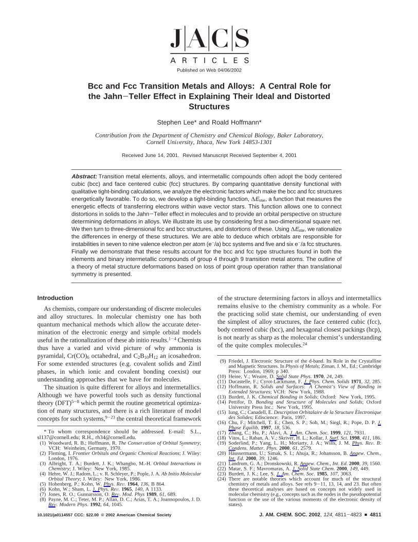
Consider a metal, say tungsten, in a body centered tetragonalor bct cell, a structure in which there are two atoms in theconventional unit cell, one at the cell corner and the other atthe body center (Figure 1i). On the left side of Figure 2 weshow the DFT energy of this cell as a contour surface.25 Asvariables, the obvious unitless parameter,c/a, the axis ratio, isemployed, as well asV/Vmin. The latter parameter is the ratioof the given unit cell volume to the cell volume of the minimumenergy structure. The energy minima of this surface are atc/a= 1.0 and 1.7, with a saddlepoint atc/a ) x2 between them.
Contrast this tungsten surface with that of its neighbor in theperiodic table, rhenium (Figure 2, middle left). Re has one morevalence electron per atom (e-/a), and its energy surface ismarkedly different from that of W. For example in Re,c/a )x2 is not a saddlepoint but an energy minimum. This changeis even more pronounced if we keep the number of valenceelectrons per atom the same as Re but introduce ionicitysindeedone of the aims of our work is a theory of the geometric stabilityof alloy structures. Consider TaIr, a compound based on theelements two steps to the left and right of Re in the periodictable. As Ir is significantly more electronegative than Ta, theTa-Ir bond is partially ionic. Here we find the surface shownat the bottom of Figure 2: thec/a ) 1.0 structure is asaddlepoint, the global energy minimum is atc/a ) x2, and asecond local minimum is found nearc/a ) 0.85.26
Such multi-valley electronic surfaces are well-known in alloysand metals.27-31 Many of the transtion metal elements have
energy surfaces with a global minimum for one value ofc/aand local minima at yet other values. Nor are these local minimacalculational artifacts. Although in certain cases these localminima are not stable to nontetragonal distortion modes, forsome transition metals it has even proven possible in epitaxiallygrown thin films to isolate metastable phases which directlycorrespond to the predicted local minima structures.32-37
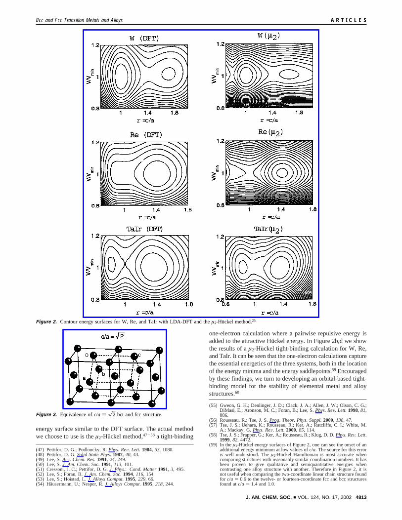
In both the previously reported electronic surfaces and in theelectronic surfaces shown in Figure 2, bothc/a of 1.0 andx2are energetically important in this body centered tetragonal (bct)geometry. The former ratio, of course, corresponds to the bccstructure. And, as we show in Figure 3, the latter ratio is actuallya face centered cubic net.38 Thus, as might have been anticipated,both the bcc and the fcc structures are global minimum energystructures. There is, however, one interesting finding. For oneor another metal structure, bcc and fcc actually correspond tosaddlepoints and not minima. Some thought will show there isno straightforward symmetry explanation for this latter finding.
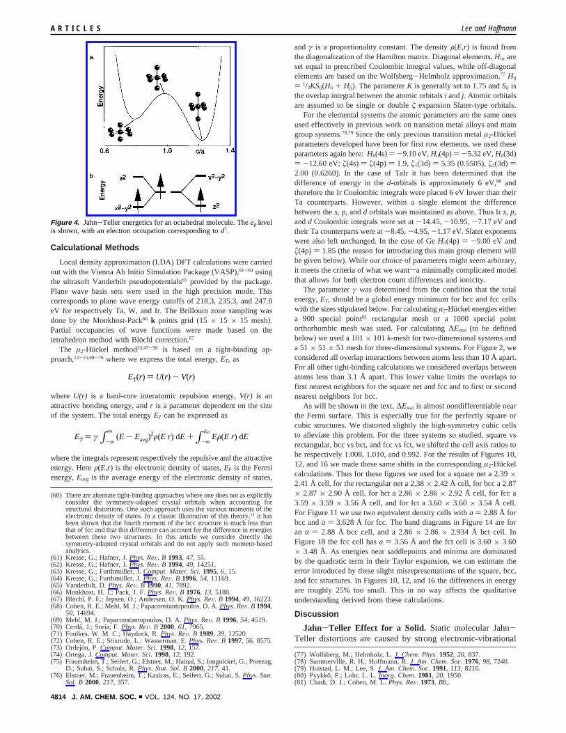
In molecular chemistry such high symmetry saddlepoints aregenerally associated with the Jahn-Teller effect.39-41 A well-known example is for Jahn-Teller-unstable octahedral mol-ecules.42 This is illustrated in Figure 4. Here the octahedron isunstable both with respect to a deformation (e.g. low spind7,d8, andd9; the figure showsd7) to a geometry with four shortand two long bonds and to the one with two short and fourlong bonds. These are two phases of aneg vibration. As in thebcc and fcc cases, the high-symmetry geometry belongs to theOh point group, the low-symmetry geometry toD4h. This formalanalogy is recapitulated in Figure 1.
A question naturally arises: Are the saddlepoints found inFigure 2 due to the solid-state equivalent of the Jahn-Tellereffect? This possibility has been mentioned before.43-46 In thisearlier work, particular attention has been paid to how thenumber of degenerate highest occupied crystal orbitals issignificantly reduced in going from the high-symmetry to thelow-symmetry structure. Here we are interested instead inapplying many of the well-developed orbital concepts from ourunderstanding of the molecular Jahn-Teller effect40,42 to thequestion of metal and alloy structure. In this regard, it is knownthat simple tight-binding or Hu¨ckel theory can be used toaccount for Jahn-Teller instabilities, and that indeed suchformalisms often provide the most clear interpretations, captur-ing the essence of the phenomenon. If this analogy holds, wemight expect that a tight-binding calculation will also have an
(25) Todorov, E.; Evans, M.; Lee, S.; Rousseau, R.Chem.: Eur. J. 2001, 7,2652.
(26) The true TaIr structure is doubly hexagonal closest packed, dhcp, a structureintermediate between fcc and hcp. In Figure 2, however, the only accessedclosest packed structure is fcc, a structure whose energy is fairly close tothat of dhcp. Hence in this figure fcc appears to be the global minimum.
(27) Sliwko, V. L.; Mohn, P.; Schwarz, K.; Blaha, P.J. Phys.: Condens. Matter1996, 8, 799.
(28) Sob, M.; Wang, L.; Vitek, V.Comput. Mater. Sci. 1997, 8, 100.(29) Watanabe, S.; Komine, T.; Kai, T.; Shiiki, K.J. Magn. Magn. Mater. 2000,
220, 277.
(30) Suzuki, T.; Shimono, M.; Kajiwara, S.Mater. Sci. Eng. 2001, A312, 104.(31) Friak, M.; Sob, M.; Vitek, V.Phys. ReV. B 2001, 63, 52405.(32) Kraft, T.; Marcus, P. M.; Methfessel, M.; Scheffler, M.Phys. ReV. B 1993,
48, 5886.(33) Craievich, P. J.; Weinert, M.; Sanchez, J. M.; Watson, R. E.Phys. ReV.
Lett. 1994, 72, 3076.(34) Alippi, P.; Marcus, P. M.; Schleffer, M.Phys. ReV. Lett. 1997, 78, 3892.(35) Tian, Y.; Jona, F.; Marcus, P. M.Phys. ReV. B 1998, 58, 14051.(36) Qiu, S. L.; Marcus, P. M.; Ma, H.J. Appl. Phys. 2000, 87, 5932.(37) Jona, F.; Marcus, P. M.Phys. ReV. B 2001, 63, 094113.(38) This path has a long history in theoretical metallurgy; it goes back to a
paper by Bain (see: Bain, E. C.Trans. AIME 1924, 70, 25).(39) Jahn, H. A.; Teller, E.Proc. R. Soc. 1937, A161, 220.(40) Bartell, L. S.J. Chem. Educ. 1968, 45, 754.(41) Pearson, R. G.Proc. Natl. Acad. Sci. U.S.A.1975, 72, 2104.(42) Burdett, J. K. Molecular Shapes: Theoretical Models of Inorganic
Stereochemistry; J. Wiley: New York, 1980; pp 170-185.(43) Ashkenazi, J.; Darcorogna, M.; Peter, M.; Talmor, Y.; Walker, E.;
Steinemann, S.Phys. ReV. B 1978, 18, 4120.(44) Asano, S.; Ishida, S.J. Phys. Soc. Jpn.1985, 54, 4241.(45) Fujii, S.; Ishida, S.; Asano, S.J. Phys. Soc. Jpn.1989, 58, 3657.(46) Sakuma, A.; Yuasa, S.; Miyajima, H.; Otani, Y.J. Phys. Soc. Jpn.1995,
64, 4914.
Figure 1. D4h to Oh to D4h distortion for (i) the body centered tetragonal(bct) structure and (ii) an octahedron.
A R T I C L E S Lee and Hoffmann
4812 J. AM. CHEM. SOC. 9 VOL. 124, NO. 17, 2002
energy surface similar to the DFT surface. The actual methodwe choose to use is theµ2-Huckel method,47-58 a tight-binding
one-electron calculation where a pairwise repulsive energy isadded to the attractive Hu¨ckel energy. In Figure 2b,d we showthe results of aµ2-Huckel tight-binding calculation for W, Re,and TaIr. It can be seen that the one-electron calculations capturethe essential energetics of the three systems, both in the locationof the energy minima and the energy saddlepoints.59 Encouragedby these findings, we turn to developing an orbital-based tight-binding model for the stability of elemental metal and alloystructures.60
(47) Pettifor, D. G.; Podloucky, R.Phys. ReV. Lett. 1984, 53, 1080.(48) Pettifor, D. G.Solid State Phys. 1987, 40, 43.(49) Lee, S.Acc. Chem. Res. 1991, 24, 249.(50) Lee, S.J. Am. Chem. Soc. 1991, 113, 101.(51) Cressoni, J. C.; Pettifor, D. G.J. Phys.: Cond. Matter 1991, 3, 495.(52) Lee, S.; Foran, B.J. Am. Chem. Soc. 1994, 116, 154.(53) Lee, S.; Hoistad, L.J. Alloys Comput. 1995, 229, 66.(54) Hausermann, U.; Nesper, R.J. Alloys Comput. 1995, 218, 244.
(55) Gweon, G. H.; Denlinger, J. D.; Clack, J. A.; Allen, J. W.; Olson, C. G.;DiMasi, E.; Aronson, M. C.; Foran, B.; Lee, S.Phys. ReV. Lett. 1998, 81,886.
(56) Rousseau, R.; Tse, J. S.Prog. Theor. Phys. Suppl.2000, 138, 47.(57) Tse, J. S.; Uehara, K.; Rousseau, R.; Ker, A.; Ratcliffe, C. I.; White, M.
A.; Mackay, G.Phys. ReV. Lett. 2000, 85, 114.(58) Tse, J. S.; Frapper, G.; Ker, A.; Rousseau, R.; Klug, D. D.Phys. ReV. Lett.
1999, 82, 4472.(59) In theµ2-Huckel energy surfaces of Figure 2, one can see the onset of an
additional energy minimum at low values ofc/a. The source for this erroris well understood. Theµ2-Huckel Hamiltonian is most accurate whencomparing structures with reasonably similar coordination numbers. It hasbeen proven to give qualitative and semiquantitative energies whencontrasting one alloy structure with another. Therefore in Figure 2, it isnot useful when comparing the two-coordinate linear chain structure foundfor c/a ) 0.6 to the twelve- or fourteen-coordinate fcc and bcc structuresfound atc/a ) 1.4 and 1.0.
Figure 2. Contour energy surfaces for W, Re, and TaIr with LDA-DFT and theµ2-Huckel method.25
Figure 3. Equivalence ofc/a ) x2 bct and fcc structure.
Bcc and Fcc Transition Metals and Alloys A R T I C L E S
J. AM. CHEM. SOC. 9 VOL. 124, NO. 17, 2002 4813
Calculational Methods
Local density approximation (LDA) DFT calculations were carriedout with the Vienna Ab Initio Simulation Package (VASP),61-64 usingthe ultrasoft Vanderbilt pseudopotentials65 provided by the package.Plane wave basis sets were used in the high precision mode. Thiscorresponds to plane wave energy cutoffs of 218.3, 235.3, and 247.8eV for respectively Ta, W, and Ir. The Brillouin zone sampling wasdone by the Monkhost-Pack66 k points grid (15× 15 × 15 mesh).Partial occupancies of wave functions were made based on thetetrahedron method with Blo¨chl correction.67
The µ2-Huckel method23,47-58 is based on a tight-binding ap-proach,12-15,68-76 where we express the total energy,ET, as
where U(r) is a hard-core interatomic repulsion energy,V(r) is anattractive bonding energy, andr is a parameter dependent on the sizeof the system. The total energyET can be expressed as
where the integrals represent respectively the repulsive and the attractiveenergy. HereF(E,r) is the electronic density of states,EF is the Fermienergy,Eavg is the average energy of the electronic density of states,
andγ is a proportionality constant. The densityF(E,r) is found fromthe diagonalization of the Hamilton matrix. Diagonal elements,Hii, areset equal to prescribed Coulombic integral values, while off-diagonalelements are based on the Wolfsberg-Helmholz approximation,77 Hij
) 1/2KSij(Hii + Hjj). The parameterK is generally set to 1.75 andSij isthe overlap integral between the atomic orbitalsi andj. Atomic orbitalsare assumed to be single or doubleú expansion Slater-type orbitals.
For the elemental systems the atomic parameters are the same onesused effectively in previous work on transition metal alloys and maingroup systems.78,79 Since the only previous transition metalµ2-Huckelparameters developed have been for first row elements, we used theseparameters again here:Hii(4s)) -9.10 eV,Hii(4p)) -5.32 eV,Hii(3d)) -12.60 eV;ú(4s)) ú(4p) ) 1.9,ú1(3d) ) 5.35 (0.5505),ú2(3d) )2.00 (0.6260). In the case of TaIr it has been determined that thedifference of energy in thed-orbitals is approximately 6 eV,80 andtherefore the Ir Coulombic integrals were placed 6 eV lower than theirTa counterparts. However, within a single element the differencebetween thes, p, andd orbitals was maintained as above. Thus Irs, p,andd Coulombic integrals were set at-14.45,-10.95,-7.17 eV andtheir Ta counterparts were at-8.45,-4.95,-1.17 eV. Slater exponentswere also left unchanged. In the case of GeHii(4p) ) -9.00 eV andú(4p) ) 1.85 (the reason for introducing this main group element willbe given below). While our choice of parameters might seem arbitrary,it meets the criteria of what we wantsa minimally complicated modelthat allows for both electron count differences and ionicity.
The parameterγ was determined from the condition that the totalenergy,ET, should be a global energy minimum for bcc and fcc cellswith the sizes stipulated below. For calculatingµ2-Huckel energies eithera 900 special point81 rectangular mesh or a 1000 special pointorthorhombic mesh was used. For calculating∆Estar (to be definedbelow) we used a 101× 101k-mesh for two-dimensional systems anda 51× 51× 51 mesh for three-dimensional systems. For Figure 2, weconsidered all overlap interactions between atoms less than 10 Å apart.For all other tight-binding calculations we considered overlaps betweenatoms less than 3.1 Å apart. This lower value limits the overlaps tofirst nearest neighbors for the square net and fcc and to first or secondnearest neighbors for bcc.
As will be shown in the text,∆Estar is almost nondifferentiable nearthe Fermi surface. This is especially true for the perfectly square orcubic structures. We distorted slightly the high-symmetry cubic cellsto alleviate this problem. For the three systems so studied, square vsrectangular, bcc vs bct, and fcc vs fct, we shifted the cell axis ratios tobe respectively 1.008, 1.010, and 0.992. For the results of Figures 10,12, and 16 we made these same shifts in the correspondingµ2-Huckelcalculations. Thus for these figures we used for a square net a 2.39×2.41 Å cell, for the rectangular net a 2.38× 2.42 Å cell, for bcc a 2.87× 2.87× 2.90 Å cell, for bct a 2.86× 2.86× 2.92 Å cell, for fcc a3.59× 3.59× 3.56 Å cell, and for fct a 3.60× 3.60× 3.54 Å cell.For Figure 11 we use two equivalent density cells witha ) 2.88 Å forbcc anda ) 3.628 Å for fcc. The band diagrams in Figure 14 are foran a ) 2.88 Å bcc cell, and a 2.86× 2.86 × 2.934 Å bct cell. InFigure 18 the fcc cell hasa ) 3.56 Å and the fct cell is 3.60× 3.60× 3.48 Å. As energies near saddlepoints and minima are dominatedby the quadratic term in their Taylor expansion, we can estimate theerror introduced by these slight misrepresentations of the square, bcc,and fcc structures. In Figures 10, 12, and 16 the differences in energyare roughly 25% too small. This in no way affects the qualitativeunderstanding derived from these calculations.
Discussion
Jahn-Teller Effect for a Solid. Static molecular Jahn-Teller distortions are caused by strong electronic-vibrational
(60) There are alternate tight-binding approaches where one does not as explicitlyconsider the symmetry-adapted crystal orbitals when accounting forstructural distortions. One such approach uses the various moments of theelectronic density of states. In a classic illustration of this theory,11 it hasbeen shown that the fourth moment of the bcc structure is much less thanthat of fcc and that this difference can account for the difference in energiesbetween these two structures. In this article we consider directly thesymmetry-adapted crystal orbitals and do not apply such moment-basedanalyses.
(61) Kresse, G.; Hafner, J.Phys. ReV. B 1993, 47, 55.(62) Kresse, G.; Hafner, J.Phys. ReV. B 1994, 49, 14251.(63) Kresse, G.; Furthmu¨ller, J. Comput. Mater. Sci. 1995, 6, 15.(64) Kresse, G.; Furthmu¨ller, J. Phys. ReV. B 1996, 54, 11169.(65) Vanderbilt, D.Phys. ReV. B 1990, 41, 7892.(66) Monkhost, H. J.; Pack, J. F.Phys. ReV. B 1976, 13, 5188.(67) Blochl, P. E.; Jepsen, O.; Andersen, O. K.Phys. ReV. B 1994, 49, 16223.(68) Cohen, R. E.; Mehl, M. J.; Papaconstantopoulos, D. A.Phys. ReV. B 1994,
50, 14694.(69) Mehl, M. J.; Papaconstantopoulos, D. A.Phys. ReV. B 1996, 54, 4519.(70) Cerda´, J.; Soria, F.Phys. ReV. B 2000, 61, 7965.(71) Foulkes, W. M. C.; Haydock, R.Phys. ReV. B 1989, 39, 12520.(72) Cohen, R. E.; Stixrude, L.; Wasserman, E.Phys. ReV. B 1997, 56, 8575.(73) Ordejon, P.Comput. Mater. Sci. 1998, 12, 157.(74) Ortega, J.Comput. Mater. Sci. 1998, 12, 192.(75) Frauenheim, T.; Seifert, G.; Elstner, M.; Hainal, S.; Jungnickel, G.; Porezag,
D.; Suhai, S.; Scholz, R.Phys. Stat. Sol. B 2000, 217, 41.(76) Elstner, M.; Frauenheim, T.; Kaxiras, E.; Seifert, G.; Suhai, S.Phys. Stat.
Sol. B 2000, 217, 357.
(77) Wolfsberg, M.; Helmholz, L.J. Chem. Phys. 1952, 20, 837.(78) Summerville, R. H.; Hoffmann, R.J. Am. Chem. Soc. 1976, 98, 7240.(79) Hoistad, L. M.; Lee, S.J. Am. Chem. Soc. 1991, 113, 8216.(80) Pyykko, P.; Lohr, L. L. Inorg. Chem. 1981, 20, 1950.(81) Chadi, D. J.; Cohen, M. L.Phys. ReV. 1973, B8,.
Figure 4. Jahn-Teller energetics for an octahedral molecule. Theeg levelis shown, with an electron occupation corresponding tod7.
ET(r) ) U(r) - V(r)
ET ) γ ∫-∞
∞(E - Eavg)
2F(E r) dE + ∫-∞
EFEF(E r) dE
A R T I C L E S Lee and Hoffmann
4814 J. AM. CHEM. SOC. 9 VOL. 124, NO. 17, 2002
coupling. There are several equivalent ways to describe whattranspires; the one we choose is an orbital-based description.In this language, the Jahn-Teller phenomenon is characteristicof a set of partially occupied highest occupied molecular orbitals(HOMO). In general these energetically degenerate HOMOsbelong to the same irreducible representation of the molecularsymmetry group. The distortion (an excursion along a normalmode) lifts the degeneracy. Solid-state equivalents of the Jahn-Teller effect are well-known. The best studied are the Peierlsdistortion82 and charge density waves (CDW).83-85 There is,however, one notable difference between the molecular Jahn-Teller effect and the Peierls or CDW distortion.In the formercase the lost symmetry element is a point group operation; inthe latter it is a translation. In the bcc, fcc, and bct cells, whilethe conventional crystallographic cells have more than one atom,the primitive cells all have only one atom each. Hence in goingfrom bcc to bct to fcc, there is no loss of translational symmetry.To analyze the effect of change of symmetry on these systemswe must turn to the full space group of the crystal and not justits translational portion.
We recall that a crystal orbital is a Bloch function:ΦkB ) (1/xN)∑eikB‚rbj φj, wherekB is thek-vector,rbj the atomic positions,and φj the atomic orbitals. If we now apply a point groupoperation of the crystal,R, to this Bloch function, we find:
In the penultimate equality we use the fact that a dot productis proportional to the angle between two vectors; thus if onerotates just one of the two vectors in the dot product as inkB‚Rrbj
this is equivalent to rotating the other vector in the dot productby an equal and opposite rotation as inR-1kB‚rbj.
As the above expressions demonstrate the equality ofRΦkB
andΦR-1kB, the point group operation mapsΦkB onto ΦR-1kB, andhence these two Bloch functions belong to the same irreduciblerepresentation. Furthermore, by definition,R-1 is also an elementof the same point group. It is conventional to call the set ofvectors{RkB}, whereR is any point group operation componentof a space group element, a star of reciprocal vectors, orkstar.86
A Two-Dimensional Model.We now consider howkstarcanhelp in the analysis of a Jahn-Teller distortion in a solid, i.e.a distortion in which the point group portion of the space groupis changed but where the translational portion remains unaf-fected. To understand the situation we need to go back to asimpler model than our three-dimensional lattice, yet one whichcaptures the physical essence of the phenomenon. In this spirit,consider a simple square net of germanium atoms that undergoesa distortion to a simple rectangular net. This distortion isillustrated in Figure 5. For the sake of simplicity we restrictthe valence orbitals to thep-manifold and assume (in the spiritof a Huckel model) that there is interaction between nearestneighbors only. In such a case there is no mixing between the
px, py, andpz sets. The energies of the Bloch crystal orbitalsare illustrated in Figure 6. These energies are simply understood.For example, forpx the lowest energy orbital is atkB ) (1/2, 0)and the highest energy orbital is atkB ) (0, 1/2) as these orbitalsare respectively purely bonding (σ andπ) and purely antibond-ing. Similarly, at these samekB-vectors, thepz orbitals arenonbonding.
In the undistorted square net a 90° rotation is a symmetryoperation, andkB ) (1/2, 0) andkB ) (0, 1/2) belong to the samekstar. Thus, thepz based crystal orbitals at these twok-pointsbelong to the same irreducible representation. But for therectangular net a 90° rotation is not a symmetry operation, andthese two orbitals are no longer degenerate. This is shown inFigure 7a. If we assume a band-filling of three electrons peratom (e-/a) the px, py, and pz are each filled with a single
(82) Peierls, R. E.Quantum Theory of Solids; Clarendon Press: Oxford, 1955.(83) Wilson, J. A.; DiSalvo, F. J.; Mahajan, S.AdV. Phys. 1975, 24, 117.(84) Monceau, P.; Ong, N. P.; Portis, A. M.; Meerschaut, A. M.; Rouxel, J.
Phys. ReV. Lett. 1976, 37, 602.(85) Canadell, E.; Whangbo, M. H.Chem. ReV. 1991, 91, 965.(86) Lax, M. Symmetry Principles in Solid State and Molecular Physics; J.
Wiley: New York, 1974.
RΦkB ) R{ 1
xN∑eikB‚ rbj φj} ) 1
xN∑eikB‚Rrbj Rφj )
1
xN∑eikB‚Rrbj φj ) 1
xN∑eiR-1kB‚ rbj φj ) ΦR-1kB
Figure 5. Distortion of a square to a rectangular net.
Figure 6. Energy contour map of square netpx, py, andpz orbitals. Energiesare color coded. Red corresponds to bonding, green to nonbonding, andblue to antibonding.
Bcc and Fcc Transition Metals and Alloys A R T I C L E S
J. AM. CHEM. SOC. 9 VOL. 124, NO. 17, 2002 4815

electron, all bonding orbitals are filled, and all nonbondingorbitals are half-filled. For this number of electrons, Figure 7abegins to resemble a conventional diagram for the molecularJahn-Teller effect. Thus at 3.0 e-/a, there may be a Jahn-Teller effect stabilizing the rectangular geometry.
The picture in Figure 7a is thus reminiscent of the classicmolecular Jahn-Teller system, cyclobutadiene. In cyclobuta-diene there are fourπ molecular orbitals (Figure 7b) and fourπ-electrons. The shape of theseπ-orbitals is completelydetermined by symmetry. Were cyclobutadiene to adopt a squaregeometry there would be one bonding, one antibonding, andtwo nonbondingπ-orbitals. In a square geometry these twononbonding orbitals are degenerate and half-filled. Under adistortion fromD4h to D2h symmetry this pair of orbitals splitsinto two: one orbital becomes weakly bonding, the otherantibonding. The classic rationalization for why cyclobutadienehas aD2h ground-state geometry is that in this latter geometryall the π-electrons are in bonding orbitals.3
The strong similarity between the square and rectangular netorbitals shown in Figure 7a and the cyclobutadiene orbitalsshown in the center of Figure 7b suggests a strategy to quantifypotential Jahn-Teller effects in extended solids. It is one whichretains, as much as possible, the feel of molecular Jahn-Tellertheory. In Figure 7, we saw for both molecule and extendednet the driving force for distortion is a pair of orbitals whichare degenerate in the high-symmetry geometry but have differentenergies in the low-symmetry structure. In the cases shown in
Figure 7, this distortion is further abetted by electron transferbetween the formerly degenerate orbitals, from the situationwhere both orbitals are filled by one electron to the one whereone orbital is empty, the other filled.
In studying extended solids, we therefore focus on orbitalswhich by symmetry are degenerate in the high-symmetrystructure but are not degenerate in the low-symmetry structure.As in Figure 7, we restrict ourselves to electron transfer betweenthese symmetry related orbitals. In the language of the solidstate, we restrict electron transfer to that between twokB-vectorsbelonging to the samekstar (see above). We keep the number ofelectrons in eachkstar fixed and calculate for eachkstar thedifference in energy between the undistorted and distortedgeometry. The number of electrons in eachkstar is set equalto that found in the undistorted structure. We call this energy∆Estar(kB) or just ∆Estar. The total difference in energy can beobtained by integrating this function.
In considering this∆Estar function, we make the assumptionthat it is the interplay between crystal orbitals which are relatedto one another by symmetry that plays a central role in theJahn-Teller energetics, rather than crystal orbitals which arejust accidentally degenerate. This is a strong assumption, as inmetals there is in general a two-dimensional surface of stateswhich are accidently degenerate. Indeed, it is known that suchaccidental degeneracies can play a considerable role in metaland alloy phonon structure.43,87,88
In Figure 8 we show this∆Estar function for two differentbandfillings, 1.2 and 3.0 e-/a (electrons per atom). (We choosethese two band fillings for as we show below, they correspondto the electron counts where there are cusps in∆Estar.) For both,the∆Estar is nearly zero, except at several well-definedkstar. Asmay be seen in Figure 8, these peaks have the form of ridges.
It is especially instructive to compare these ridges with thecontour maps of thep crystal orbitals, shown previously inFigure 6. In particular, we need to concentrate on the contourlines in Figure 6 which correspond to the highest occupiedmolecular orbitals, i.e. the orbitals at the Fermi energy. Considerfirst 3.0 e-/a, where thepx, py, andpz orbitals are all half-filled.For this case, the contour lines which correspond to the highestoccupied molecular orbitals are purely nonbonding. They arethe pure green lines of Figure 6 and they are only partially filledwith electrons. For thepz crystal orbitals, these nonbondingmolecular orbitals correspond to the straight contour line thatruns from the upper left of Figure 6c to the lower right.
When one compares the green contour lines of Figure 6 withthe ∆Estar function for 3.0 e-/a, shown in Figure 8, we seesomething interesting. The ridges in the∆Estar function are atexactly the same location as the green contour lines. Why shouldsuch a correspondence exist? Recall that at 3.0 e-/a the greencontour lines indicate those orbitals which are only partiallyfilled with electrons. Recall also that the∆Estar function groupstogether the orbitals which are related to one another bysymmetry. The correspondence of the contour lines and theridges of the∆Estar function tell us that both partial orbitaloccupation and the grouping together of symmetry equivalentorbitals are important.
To understand why this is so, consider again cyclobutadiene(see Figure 7b). In cyclobutadiene’s square geometry there are
(87) Varma, C. M.; Weber, W.Phys. ReV. B 1979, 19, 6142.(88) Herper, H. C.; Hoffmann, E.; Entel, P.; Weber, W.J. Phys. IV 1995, 5,
C8-293.
Figure 7. Effect of rectangular distortion (a) on thepz kB ) (0, 1/2) andkB) (1/2, 0) orbitals of a square net for a band filling of 3 electrons per atomand (b) for theπ-orbitals of cyclobutadiene.
A R T I C L E S Lee and Hoffmann
4816 J. AM. CHEM. SOC. 9 VOL. 124, NO. 17, 2002

two partially filled symmetry-relatednonbonding orbitals. Underthe rectangular distortion they split apart in energy: one orbitalbecoming slightly bonding and the other slightly antibonding.Given the initial partial occupation of these two orbitals by justtwo electrons, the slightly bonding orbital is filled and theslightly antibonding orbital is unfilled: the system is stabilized.
For the same phenomenon to occur in the solid state, just asin cyclobutadiene, one needs again partially filled symmetry-related orbitals. There must be a set of originally degenerateorbitals which are energetically split apart by the distortion:some going down in energy and others going up in energy. Thisset of orbitals must be partially filled so that the energystabilization found from the set of stabilized orbitals is notcounteracted by occupation of the others. In the case of thesquare to rectangle distortion for 3.0 e-/a, the partially filledorbitals are the orbitals which correspond to the green contourlines in Figure 6. The symmetry-related degenerate orbitalscorrespond to the individualkstar. Hence it is only these greencontour orbitals and theirkstarrelated orbitals that cause the solid-state Jahn-Teller distortion.
However, Figure 8 also shows that not all Fermi surface statescontribute equally to∆Estar (in a metal the HOMO orbitals aresaid to be on the Fermi surface). At 1.2 e-/a, the ridge in the∆Estar function is highest wherekstar is (1/2, 1/2) while at 3.0e-/a, the ridge is highest at (1/2, 0). Actually, these band fillingsare not just pedagogical examplesswe have surveyed the fullrange of electron populations and these two band-fillings arethose with the largest values of∆Estar. It should be noted though
the square net is alternant (by alternant we mean there are noodd member rings of bonded atoms).89 At the Huckel level, thisresults in a pairing of filled and unfilled levels; thus∆Estar at4.8 e-/a (1.2 holes per atom) is by symmetry the same as thatat 1.2 e-/a.
The explanation for the relative heights of these ridges maybe found by examining theshapeof the orbitals in thekstar
themselves. We consider first the 1.2 e-/a system. AtkB ) (1/2,1/2), the two energetically degenerate Fermi surface orbitals arethepx andpy orbitals. Thepx orbital, shown at the left of Figure9, is σ-bonding in the horizontal direction, butπ-antibondingin the vertical direction. The converse is true for thepy orbital.Under the rectangular distortion, horizontal interactions becomestronger and vertical interactions weaker. As thepx orbital isbonding in one direction and antibonding in the other, such adistortion causes a large decrease in crystal orbital energy;similarly, thepy orbital increases in energy. The result is a largedriving force for the Jahn-Teller effect associated with thispair of orbitals at this particular electron count.
For 3.0 e-/a the most energetically important orbitals are thepz orbitals atkB ) (1/2, 0) and (0,1/2). These were shown inFigure 7a. One member of this pair of orbitals is bonding inthe horizontal direction and antibonding in the vertical direction,while the opposite is true for its partner orbital. Again, the resultis a large associated Jahn-Teller effect.
(89) Coulson, C. A.; Rushbrooke, G. S.Proc. Cambridge Philos. Soc. 1940,36, 193.
Figure 8. ∆Estar for a square vs a rectangular net: (a and b) at 1.2 and (c and d) at 3.0 e-/a.
Bcc and Fcc Transition Metals and Alloys A R T I C L E S
J. AM. CHEM. SOC. 9 VOL. 124, NO. 17, 2002 4817

∆Estaris also useful in analyzing the total difference in energy.In Figure 10a, we show the results of aµ2-Huckel calculationfor the square and rectangular net. Plotted is the difference inenergy between these two structures,∆Eµ2, as a function of bandfilling. The curves are plotted so that a positive value corre-sponds to the square net being more stable and a negative valueto the rectangular net being more stable. It can be seen thatnear 1.2, 3.0, and 4.8 e-/a, the rectangular structure is preferred.
These are exactly the electron counts discussed in the precedingparagraphs. As Figure 10a shows, the magnitude of thisdifference in energy is controlled by the size of the distortion.As the square net (b/a ) 1.0) is an energetic saddlepoint, weexpect that the quadratic term will dominate a Taylor seriesexpansion around the saddlepoint geometry. This quadraticrelation roughly holds betweenb/a ) 1.02 and 1.05, but is lesscorrect at higherb/a values.
In Figure 10b, we compare directly∆Eµ2 with ∆Estar for b/a) 1.02, where we have integrated the latter function overk-space.90 It can be seen that the two functions are quite similar.Both functions have sharp spikes near 1.2, 3.0, and 4.8 e-/a.The functions differ by an approximately parabolic function thatis greatest at the half-filled band and zero at the band edges.Such an error is expected, as we have not made an interatomicrepulsion correction in∆Estarbut have in∆Eµ2. Such a correctionis expected to be parabolic.23
Finally, in Figure 10c we compare these difference in energycurves with the electronic density of states (DOS). It isconventional to plot the DOS as a function of the Fermi energy.Here we plot the DOS as a function of band-filling. In this waywe can directly compare parts b and c in Figure 10. We seethat the band fillings with the largest Fermi surface, i.e. thegreatest number of highest occupied molecular orbital states,are the same band fillings for which the Jahn-Teller distortionis strongest. The shape of the density of states can be understoodby reexamining Figure 6. It is precisely at these electronconcentrations where the contour lines intersect the corners ofthe diagrams. These corners are high symmetry points ink-space, where bands in the band diagram have zero slope.91
Therefore, it is at these electron counts where not only the Fermisurface contour lines are longest, but also the Fermi surfacecontour slopes are flattest. Consequently it is at thesek-pointswhere the electronic density of states is highest.
However, our preceding analysis at 1.2 and 3.0 e-/a showsthat this correspondence is somewhat misleading. As wediscussed earlier, it is not the length or width of the ridges in∆Estar which are important, rather it is the magnitude of themajor peaks in these ridges. A similar phenomenon is foundfor molecular Jahn-Teller distortions. For example, in transitionmetal octahedral complexes there are threet2g orbitals and onlytwo eg orbitals, but it is theeg-based Jahn-Teller instabilitieswhich have the greatest distortions.42 The reason for this isclearstheeg levels areσ-antibonding, thet2g levelsσ-nonbond-ing (or π-antibonding if the ligands areπ donors).
If it is a coincidence that the electron fillings with the largestelectronic density of states are also the ones where∆Estar hasits largest values, what is the reason for it? Again we turn toFigure 6. It is the orbitals at the corners of the diagrams in Figure6 that are maximally bonding and antibonding. And more tothe point, it is at the corners where orbitals are maximallybonding along one axis direction and antibonding along theother.∆Estar is therefore maximized when these corner orbitalslie on the Fermi surface. Similarly it is the contours which passthrough these same corner states which are both flattest and
(90) We choose such a small distortion as the interest in this paper is the Jahn-Teller distortion itself and hence the energetic behavior near the high-symmetry structure.
(91) Ashcroft, N. W.; Mermin, N. D.Solid State Physics; Holt, Rinehart andWinston: New York, 1976; p 145.
Figure 9. Effect of rectangular distortion of a square net on thepx andpy
kB ) (1/2, 1/2) orbitals for a band filling of 1.2 electrons per atom.
Figure 10. (a) Difference inµ2-Huckel energies between the square netand a rectangular net. Negative values correspond to the rectangular netbeing more stable. (b) Comparison of∆Estar and ∆Eµ2 for the square vsrectangular (b/a ) 1.02) net. Note the∆E-scale is different from Figure10a. (c) The square net electronic density of states as a function of bandfilling.
A R T I C L E S Lee and Hoffmann
4818 J. AM. CHEM. SOC. 9 VOL. 124, NO. 17, 2002

longest; this is where one finds the greatest values of theelectronic density of states.
Thus the corners in Figure 6 determine both the maximumvalues of∆Estar and the maxima in the density of states. Thisaccounts for the agreement between parts b and c in Figure 10.We note thatkB-vectors such asΓ, (1/2, 0), (0,1/2), and (1/2, 1/2)are often the places where orbitals are maximally bonding orantibonding. This is especially true for simple systems. Thusalthough it is a coincidence that there is a correlation between∆Estar and the density of states, it is a coincidence that willfrequently occur.
With the experience gained from this two-dimensionalproblem, we are ready to apply the∆Estar analysis to the three-dimensional problems of central interest to us, the structure ofmetals and alloys.
Bcc to Bct Distortion. Group 3 and 4 transition metalelements adopt the hcp structure, group 5 and 6 elements thebcc structure, nonmagnetic group 7 and 8 elements the hcpstructure, and nonmagnetic group 9-11 elements the fccstructure.92 In accounting for these facts it is clear that thevalences-, p-, and d-orbitals can all potentially play a role.However, it is well established that it is thed-orbitals whichare most important. Thus Pettifor has used a near neighbord-orbital model to correctly determine differences in energybetween the bcc, fcc, and hcp systems.93 His results agree withthe above experimental findings with one exception: near thecompletely filledd-band, Pettifor’s calculations suggest that bccis preferred over fcc.
In Figure 11 we present the results ofµ2-Huckel calculationscomparing the fcc and bcc structures. Two different models arepresented. In the first, a full set ofs-, p-, and d-orbitals isconsidered, while in the second onlyd-orbitals are used. Todirectly compare these calculations we need to assign theoccupancy of thes- andp-bands in thed-orbital model. We doso by making the simple assumption that thep-band remainsunfilled and that thes-band occupation is proportional to thed-band occupation. We therefore multiply thed-band electronconcentration by6/5 to determine the appropriate e-/a level. AsFigure 11 shows, the two models are comparable. However,near the filleds- andd-band limit, thed-orbital model has bcctoo stable with respect to fcc. This is the same error as found
in the Pettifor results. It suggests that for such late transitionmetal elementss- and p-orbital effects must be explicitlyconsidered.
In the systems shown in Figure 2, the average electronconcentrations are 6 e-/a while for Re and TaIr the concentrationis 7 e-/a. At such lower electron counts, ad-orbital modelcaptures the principal energetic features. As our goal is toexplain, using the simplest picture possible, the energetics ofthese lower electron count systems, we consider here, as hadPettifor, near neighbord-orbital interactions alone.
We consider first the stability of the bcc net with respect toa bct distortion (c/a ) 1.02), see Figure 1i. We show the resultsof both aµ2-Huckel calculation and an integrated∆Estarfunctionfor such a distortion in Figure 12a. As can be seen, the twofunctions closely track one another. The bcc undistorted structureis preferred near 5d-electrons per atom, but from 6 to 9d-electrons per atom the bct distortion is lower in energy.Recalling the approximate factor of6/5 necessary to convert theseband-fillings to periodic table group numbers, these resultssuggest that group 5 and 6 transtion metal elements in the bccstructure are not Jahn-Teller unstable, but that group 7 andabove elements are Jahn-Teller unstable. This is borne outexperimentally. All nonmagnetic transition metal elementsbelonging to group 7 or higher or group 4 and lower adoptclosest packed structures, while group 5 and 6 elements adoptthe bcc structure. These results cannot be used to distinguishthe fcc from the hcp structures,94 but as fcc and hcp arestructurally similar, the differences in energy between them aresmall when compared to their differences in energy with respectto the bcc structure. We can therefore assume that the hcp vsbcc energies are fairly similar to the ones shown in Figure 12.That this is so is verified by Pettifor’s original results on thefcc, hcp, and bcc structures. In his work, the differences inenergy between fcc and bcc were five times greater than thosebetween fcc and hcp.
We can compare these energy difference curves to theelectronic density of states plotted as a function of electron
(92) Massalski, T. B.; Okamoto, H.; Subramanian, P. R., Eds.Binary Alloy PhaseDiagrams, 2nd ed.; American Society for Metals: Metal Park, OH, 1990.
(93) Pettifor, D. G.Bonding and Structure of Molecules and Solids; OxfordScience: Oxford, England, 1995; pp 223-226.
(94) Hcp has two atoms in its primitive cell. Hence any study comparing Jahn-Teller instabilities of fcc with respect to hcp requires the use of bothrotational and translational symmetry elements, a study outside the compassof the present work.
Figure 11. Difference inµ2-Huckel energies between bcc and fcc. Negativevalues correspond to the fcc being more stable. In thed-only model, thed-band electron concentration is multiplied by6/5 to simulate partials-bandfillings.
Figure 12. (a) Difference in energies between bcc and bct (c/a ) 1.02)using ad-orbital only model. Negative values correspond to bct being morestable. Differences in energy are per atom. (b) Electronic density of statesfor bcc given as a function ofd-orbital band-filling.
Bcc and Fcc Transition Metals and Alloys A R T I C L E S
J. AM. CHEM. SOC. 9 VOL. 124, NO. 17, 2002 4819
concentration. This latter curve is shown in Figure 12b. As inthe case of the square to rectangular distortion discussedpreviously, there is a coincidence between the electron countswhich are Jahn-Teller unstable and the electron counts whichhave the largest Fermi surface area. The two maxima in thedensity of states are found near one and eightd-electrons peratom. Conversely, the minimum Fermi surface is found nearfive d-electrons per atom, the electron concentration where thereis no Jahn-Teller driving force.
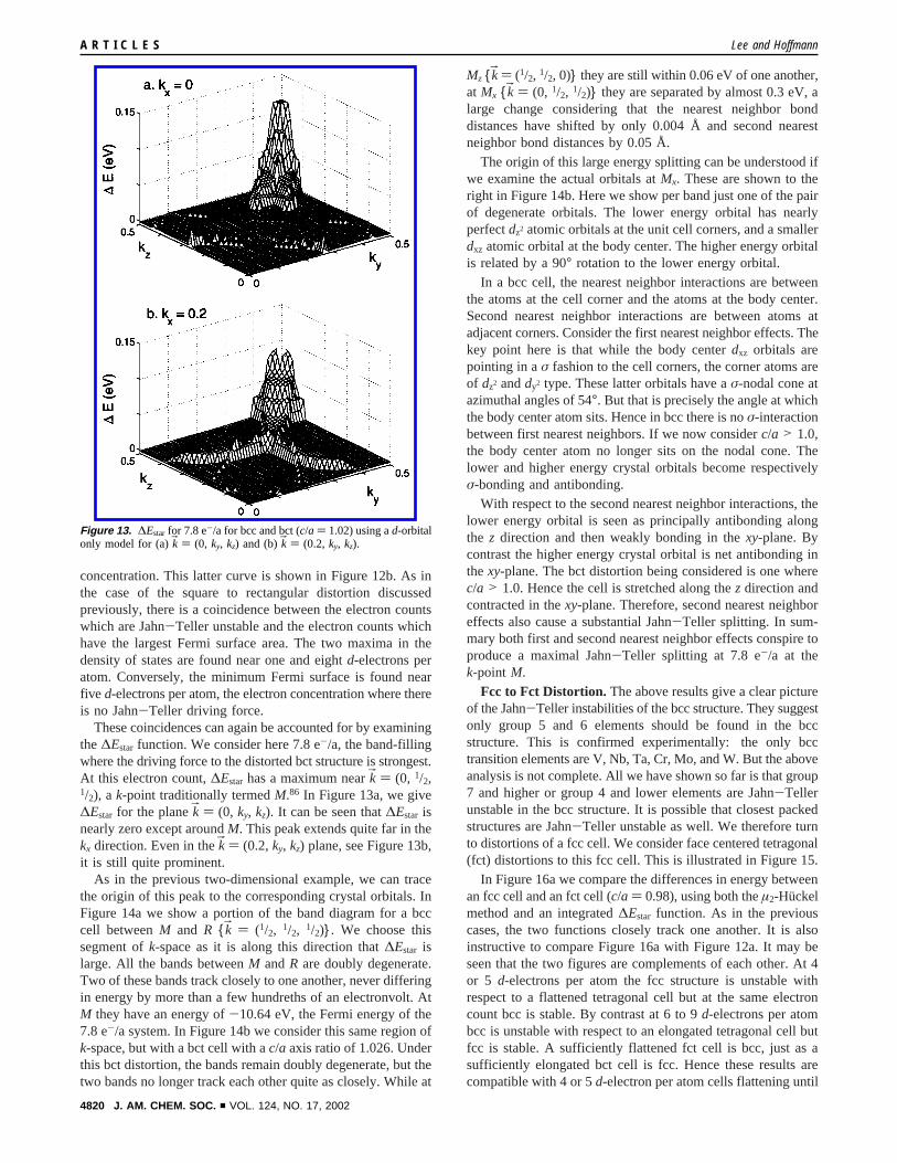
These coincidences can again be accounted for by examiningthe∆Estar function. We consider here 7.8 e-/a, the band-fillingwhere the driving force to the distorted bct structure is strongest.At this electron count,∆Estar has a maximum nearkB ) (0, 1/2,1/2), a k-point traditionally termedM.86 In Figure 13a, we give∆Estar for the planekB ) (0, ky, kz). It can be seen that∆Estar isnearly zero except aroundM. This peak extends quite far in thekx direction. Even in thekB ) (0.2,ky, kz) plane, see Figure 13b,it is still quite prominent.
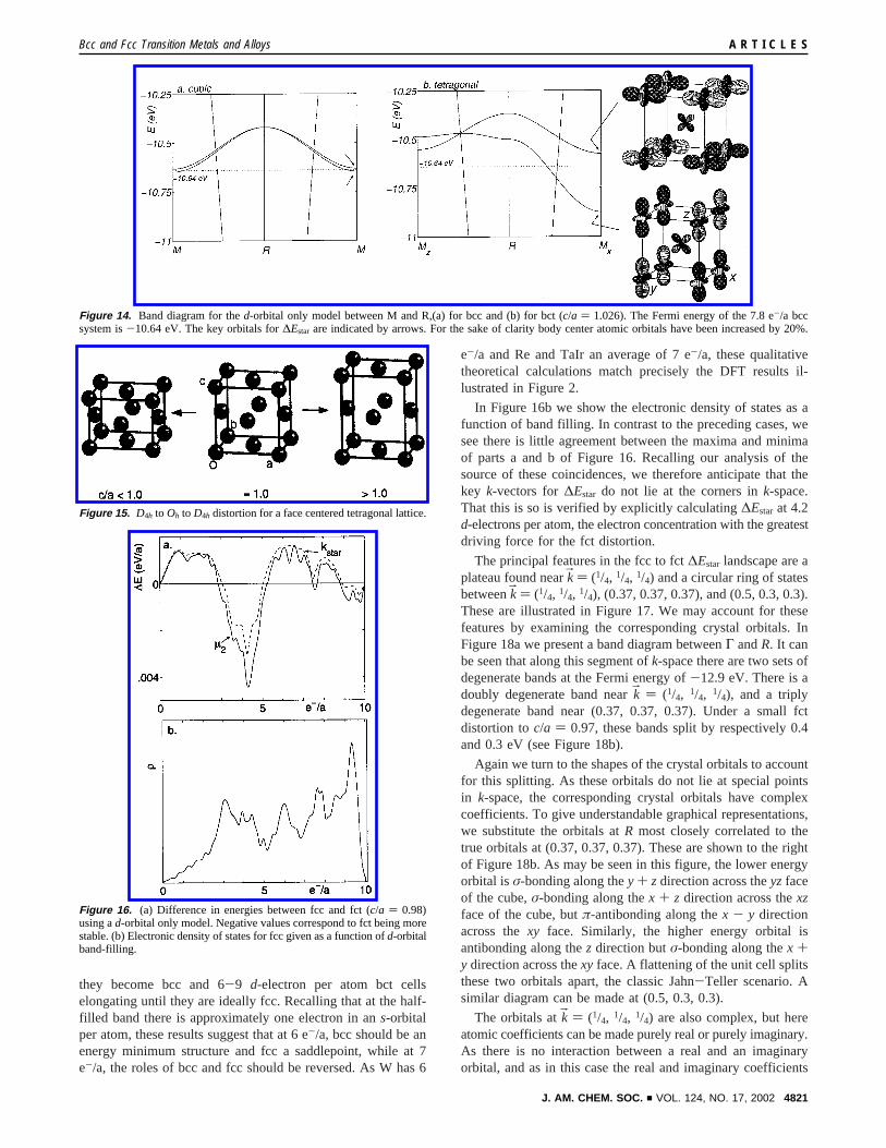
As in the previous two-dimensional example, we can tracethe origin of this peak to the corresponding crystal orbitals. InFigure 14a we show a portion of the band diagram for a bcccell betweenM and R {kB ) (1/2, 1/2, 1/2)}. We choose thissegment ofk-space as it is along this direction that∆Estar islarge. All the bands betweenM andR are doubly degenerate.Two of these bands track closely to one another, never differingin energy by more than a few hundreths of an electronvolt. AtM they have an energy of-10.64 eV, the Fermi energy of the7.8 e-/a system. In Figure 14b we consider this same region ofk-space, but with a bct cell with ac/a axis ratio of 1.026. Underthis bct distortion, the bands remain doubly degenerate, but thetwo bands no longer track each other quite as closely. While at
Mz {kB ) (1/2, 1/2, 0)} they are still within 0.06 eV of one another,at Mx {kB ) (0, 1/2, 1/2)} they are separated by almost 0.3 eV, alarge change considering that the nearest neighbor bonddistances have shifted by only 0.004 Å and second nearestneighbor bond distances by 0.05 Å.
The origin of this large energy splitting can be understood ifwe examine the actual orbitals atMx. These are shown to theright in Figure 14b. Here we show per band just one of the pairof degenerate orbitals. The lower energy orbital has nearlyperfectdz2 atomic orbitals at the unit cell corners, and a smallerdxz atomic orbital at the body center. The higher energy orbitalis related by a 90° rotation to the lower energy orbital.
In a bcc cell, the nearest neighbor interactions are betweenthe atoms at the cell corner and the atoms at the body center.Second nearest neighbor interactions are between atoms atadjacent corners. Consider the first nearest neighbor effects. Thekey point here is that while the body centerdxz orbitals arepointing in aσ fashion to the cell corners, the corner atoms areof dz2 anddy2 type. These latter orbitals have aσ-nodal cone atazimuthal angles of 54°. But that is precisely the angle at whichthe body center atom sits. Hence in bcc there is noσ-interactionbetween first nearest neighbors. If we now considerc/a > 1.0,the body center atom no longer sits on the nodal cone. Thelower and higher energy crystal orbitals become respectivelyσ-bonding and antibonding.
With respect to the second nearest neighbor interactions, thelower energy orbital is seen as principally antibonding alongthe z direction and then weakly bonding in thexy-plane. Bycontrast the higher energy crystal orbital is net antibonding inthexy-plane. The bct distortion being considered is one wherec/a > 1.0. Hence the cell is stretched along thez direction andcontracted in thexy-plane. Therefore, second nearest neighboreffects also cause a substantial Jahn-Teller splitting. In sum-mary both first and second nearest neighbor effects conspire toproduce a maximal Jahn-Teller splitting at 7.8 e-/a at thek-point M.
Fcc to Fct Distortion. The above results give a clear pictureof the Jahn-Teller instabilities of the bcc structure. They suggestonly group 5 and 6 elements should be found in the bccstructure. This is confirmed experimentally: the only bcctransition elements are V, Nb, Ta, Cr, Mo, and W. But the aboveanalysis is not complete. All we have shown so far is that group7 and higher or group 4 and lower elements are Jahn-Tellerunstable in the bcc structure. It is possible that closest packedstructures are Jahn-Teller unstable as well. We therefore turnto distortions of a fcc cell. We consider face centered tetragonal(fct) distortions to this fcc cell. This is illustrated in Figure 15.
In Figure 16a we compare the differences in energy betweenan fcc cell and an fct cell (c/a ) 0.98), using both theµ2-Huckelmethod and an integrated∆Estar function. As in the previouscases, the two functions closely track one another. It is alsoinstructive to compare Figure 16a with Figure 12a. It may beseen that the two figures are complements of each other. At 4or 5 d-electrons per atom the fcc structure is unstable withrespect to a flattened tetragonal cell but at the same electroncount bcc is stable. By contrast at 6 to 9d-electrons per atombcc is unstable with respect to an elongated tetragonal cell butfcc is stable. A sufficiently flattened fct cell is bcc, just as asufficiently elongated bct cell is fcc. Hence these results arecompatible with 4 or 5d-electron per atom cells flattening until
Figure 13. ∆Estar for 7.8 e-/a for bcc and bct (c/a ) 1.02) using ad-orbitalonly model for (a)kB ) (0, ky, kz) and (b)kB ) (0.2, ky, kz).
A R T I C L E S Lee and Hoffmann
4820 J. AM. CHEM. SOC. 9 VOL. 124, NO. 17, 2002
they become bcc and 6-9 d-electron per atom bct cellselongating until they are ideally fcc. Recalling that at the half-filled band there is approximately one electron in ans-orbitalper atom, these results suggest that at 6 e-/a, bcc should be anenergy minimum structure and fcc a saddlepoint, while at 7e-/a, the roles of bcc and fcc should be reversed. As W has 6
e-/a and Re and TaIr an average of 7 e-/a, these qualitativetheoretical calculations match precisely the DFT results il-lustrated in Figure 2.
In Figure 16b we show the electronic density of states as afunction of band filling. In contrast to the preceding cases, wesee there is little agreement between the maxima and minimaof parts a and b of Figure 16. Recalling our analysis of thesource of these coincidences, we therefore anticipate that thekey k-vectors for∆Estar do not lie at the corners ink-space.That this is so is verified by explicitly calculating∆Estar at 4.2d-electrons per atom, the electron concentration with the greatestdriving force for the fct distortion.
The principal features in the fcc to fct∆Estar landscape are aplateau found nearkB ) (1/4, 1/4, 1/4) and a circular ring of statesbetweenkB ) (1/4, 1/4, 1/4), (0.37, 0.37, 0.37), and (0.5, 0.3, 0.3).These are illustrated in Figure 17. We may account for thesefeatures by examining the corresponding crystal orbitals. InFigure 18a we present a band diagram betweenΓ andR. It canbe seen that along this segment ofk-space there are two sets ofdegenerate bands at the Fermi energy of-12.9 eV. There is adoubly degenerate band nearkB ) (1/4, 1/4, 1/4), and a triplydegenerate band near (0.37, 0.37, 0.37). Under a small fctdistortion toc/a ) 0.97, these bands split by respectively 0.4and 0.3 eV (see Figure 18b).
Again we turn to the shapes of the crystal orbitals to accountfor this splitting. As these orbitals do not lie at special pointsin k-space, the corresponding crystal orbitals have complexcoefficients. To give understandable graphical representations,we substitute the orbitals atR most closely correlated to thetrue orbitals at (0.37, 0.37, 0.37). These are shown to the rightof Figure 18b. As may be seen in this figure, the lower energyorbital isσ-bonding along they + zdirection across theyzfaceof the cube,σ-bonding along thex + z direction across thexzface of the cube, butπ-antibonding along thex - y directionacross thexy face. Similarly, the higher energy orbital isantibonding along thez direction butσ-bonding along thex +y direction across thexy face. A flattening of the unit cell splitsthese two orbitals apart, the classic Jahn-Teller scenario. Asimilar diagram can be made at (0.5, 0.3, 0.3).
The orbitals atkB ) (1/4, 1/4, 1/4) are also complex, but hereatomic coefficients can be made purely real or purely imaginary.As there is no interaction between a real and an imaginaryorbital, and as in this case the real and imaginary coefficients
Figure 14. Band diagram for thed-orbital only model between M and R,(a) for bcc and (b) for bct (c/a ) 1.026). The Fermi energy of the 7.8 e-/a bccsystem is-10.64 eV. The key orbitals for∆Estar are indicated by arrows. For the sake of clarity body center atomic orbitals have been increased by 20%.
Figure 15. D4h to Oh to D4h distortion for a face centered tetragonal lattice.
Figure 16. (a) Difference in energies between fcc and fct (c/a ) 0.98)using ad-orbital only model. Negative values correspond to fct being morestable. (b) Electronic density of states for fcc given as a function ofd-orbitalband-filling.
Bcc and Fcc Transition Metals and Alloys A R T I C L E S
J. AM. CHEM. SOC. 9 VOL. 124, NO. 17, 2002 4821

on neighboring atoms are similar, to get a sense of its bondingnature, we can portray just the real portion of the orbital. Thesereal portions are shown in Figure 19. The lower energy orbitalis π-antibonding in thexyplane butσ-bonding in thezdirection.Its energy is therefore lowered by the fct distortion. The higherenergy orbital isσ-bonding in they direction butπ-antibondingin they + z direction. Its energy is raised by the fct distorion,causing a large Jahn-Teller splitting.
Bcc, Fcc, and Bct Binary Alloys.It is well established thatelectron counting rules true for the elements often also applyto their alloy and intermetallic counterparts.95,96 Here we
consider the relevance of the above theoretical treatment to fullyatomically ordered,97 magnetically unordered,98 low-temperaturestable92 binary transition metal alloys of group 4 through 9elements. We are interested in atomically ordered phases, asthese are the ones most easily amenable to band structurecalculations. We restrict ourselves to magnetically unordered,low-temperature stable phases, as we have not considered spininteractions or entropy effects. Finally we consider only group4-9 binary alloys, since it is only for transition metals of fairlysimilar orbital character that theµ2-Huckel method can beapplied. In Table 1, we list all phases which form in variants ofthe bcc, fcc, and bct structures and where the stoichiometriesof the two elements are either 1:1 or 1:3.97,99 The 1:2 ratiotransition metal alloys tend to form in Laves phases and henceare not often structurally related to bcc, bct, or fcc.
Three main structure types are found. The first is the well-known CsCl structure, a cubic structure with one atom at thecorner of the unit cell and the other atom type at the body center.It is an ordered bcc cell. The second is AuCu3, a structure withan fcc network of atoms, with one atom type on the cubic unitcell corner and the other on the cell faces. Finally, and mostinterestingly, there is the HgMn structure, also called the AuCuI structure. Unlike the previous two structures, this type istetragonal. This is an ordered bct arrangement with one atomat the cell corner, and the other atom at the body center.
All three structures are therefore ordered variants of bct, seeFigures 1a and 3. In Table 1 we list for each of the compounds
(95) Hume-Rothery, W.; Raynor, G. V.The Structure of Metals and Alloys;Institute of Metals, London: 1962.
(96) Hume-Rothery, W.Phase Stability in Metals and Alloys; McGraw-Hill,New York: 1965.
(97) Villars, P.; Calvert, L. D.Pearson’s Handbook of Crystallographic Datafor Intermettallic Phases; ASM International: Materials Park, OH, 1991.
(98) Wijn, H. P. J., Ed.Landoldt-Bornstein New Series: Group 3: CondensedMatter, Volume 19: Magnetic Properties of Metals, SubVolume a: 3d, 4d,5d-Elements, Alloys, and Compounds; Springer: Berlin, Germany, 1986.
(99) van Vucht, J. H. N.J. Less Comm. Met. 1966, 11, 308.
Figure 17. ∆Estar for 4.2 e-/a for fcc and fct (c/a ) 0.98) using ad-orbital only model for (a) thekB ) (kx, ky, 0.25) plane and (b) thekB ) (kx, ky, 0.37) plane.
Figure 18. Band diagram for thed-orbital only model betweenΓ and R(a) for fcc and (b) for fct (c/a ) 0.97). Numbers indicate the banddegeneracies. The Fermi energy of the 4.2 e-/a bcc system is-12.90 eV.Some of the key orbitals of∆Estar are indicated by arrows.
Figure 19. Real portion of fct (c/a ) 0.97) orbitals atkB ) (1/4, 1/4, 1/4).
A R T I C L E S Lee and Hoffmann
4822 J. AM. CHEM. SOC. 9 VOL. 124, NO. 17, 2002
thec/a ratio in terms of this bct cell and the average number ofe-/a. There is a strong correlation between the two. At 5.5 and6 e-/a, thec/a ratio is invariably 1, at 6.5 e-/a thec/a ratiorises from 1.00 to 1.18, and finally above 7.25 e-/a,c/a ) x2.This trend is in agreement with the results of Figure 12a and16a. As these figures show, at electron concentrations of 5.5d-electrons per atom (or equivalently 6.5 valence electrons peratom), both the fcc vs fct integrated∆Estar function and the bccvs bct integrated∆Estar function go through a node. Hence bcc,fcc, and bct structures with 1.0< c/a < x2 are all comparablein energy. It is exactly here that we find the tetragonal HgMnstructures. The one HgMn structure that does not obey thiselectron count rule is MnIr, a phase whose magnetic structurehas not been studied.98
These results also suggest why the tetragonal structures areso much rarer than the cubic ones. For such tetragonal structuresto occur one needs electron counts where both bcc and fcc areJahn-Teller unstable. Instead, as Figures 12a and 16a demon-
strate, these curves are complements of each other. Only nearthe nodes of the curves in these figures are distorted bct or fctcells a reasonable energetic alternative.
Conclusion
In studying the interplay of symmetry and crystal energies,solid state chemists and physicists have traditionally focusedon translational symmetry elements. In retrospect it is clear why.The preeminent example of a Jahn-Teller distortion in a crystalis the Peierls distortion,82 a distortion for one-dimensionalsystems. In one dimension the only point group operation isthe inversion center, a symmetry element that due to Friedel’slaw100 cannot play a strong energetic role in∆Estar.
In higher dimensional crystal distortions, there is generallyloss of both translational and rotational symmetry elements.Given the importance of the Peierls distortion, it is natural thatwe should focus on the former and not the latter group elements.It is nonetheless plausible that by concentrating solely on thetranslational elements, vital factors governing structural distor-tions have been ignored.
Studies involving loss of translational symmetry have demon-strated the power of maximal Fermi surface nesting, i.e., ofk-vectors which maximally couple Fermi surface states.85 Thiscan be directly contrasted to the analysis in the current work.We have found that distortion is not just driven by the numberof Fermi surface states, but also by the propensity of these statesand their corresponding orbitals for distortion. Indeed othershave found smilar effects, for example, when studying electron-phonon coupling.87 In one system we studied, fcc vs fct, theselatter propensities were a more important factor than the areaof Fermi states. It would be interesting to determine if thereare other systems where both translational and rotationalsymmetry elements play a role and where similar orbitalpropensities dominate. In such phases the maximal nestingvector might not be observed, instead a seemingly lesser nestingvector could be adopted due to its superior orbital interactions.
Acknowledgment. This work was supported by the NationalScience Foundation (Grant DMR-0073587) and by the Petro-leum Research Fund, administered by the American ChemicalSociety. We wish to thank Dr. Evgeny Todorov without whosestrong interest this project would not have been completed.
JA0114557
(100) Friedel, G.Comptes Rendus1913, 157, 1533.
Table 1. Atomically Ordered, Magnetically Unordered, LowTemperature Binary Bcc, Bct and Fcc Compounds
compd structure type e-/a c/a
TiTc CsCl 5.50 1.00HfTc CsCl 5.50 1.00VMn CsCl 6.00 1.00VTc CsCl 6.00 1.00HfRu CsCl 6.00 1.00TiOs CsCl 6.00 1.00ZrOs CsCl 6.00 1.00HfOs CsCl 6.00 1.00ZrCo CsCl 6.50 1.00HfRh CsCl 6.50 1.00TaRu HgMn 6.50 1.02NbRu HgMn 6.50 1.12TiRh HgMn 6.50 1.14TiIr HgMn 6.50 1.18MnIr HgMn 8.00 1.34NbRu3 AuCu3 7.25 1.41TiRh3 AuCu3 7.75 1.41ZrRh3 AuCu3 7.75 1.41HfRh3 AuCu3 7.75 1.41TiIr 3 AuCu3 7.75 1.41ZrIr3 AuCu3 7.75 1.41HfIr3 AuCu3 7.75 1.41VRh3 AuCu3 8.00 1.41TaRh3 AuCu3 8.00 1.41VIr3 AuCu3 8.00 1.41NbIr3 AuCu3 8.00 1.41TaIr3 AuCu3 8.00 1.41
Bcc and Fcc Transition Metals and Alloys A R T I C L E S
J. AM. CHEM. SOC. 9 VOL. 124, NO. 17, 2002 4823

![On the Jahn-Teller distortion of CH4transition metal compounds [1]. However, there have until recently been few examples of Jahn-Teller interactions in orbitally degenerate states](https://static.fdocuments.net/doc/165x107/60ab93ff058b084e2133d9b0/on-the-jahn-teller-distortion-of-ch4-transition-metal-compounds-1-however-there.jpg)


