BC3 - ToolCon - SRC51
11
analoge + digitale Tonstudiotechnik Karl Jüngling • Inh. Dipl.-Ing. Gerd Jüngling Scholtwiese 4-6 • D45966 Gladbeck • Germany • Internet: www.adt-audio.com EMail: [email protected] • Phone 0(049) 2043 51061/51117 • Fax 0(049) 2043 56844 ��������� ��������� BC3 - ToolCon - SRC51 1 System - 3 Applications Three Audio Console Systems cover the entire range of applications for an analog console; Broadcast, Live Sound and Studio Production. We at adt-audio offer console versions with special module sets for every particular applications. However, these three systems have a lot in common. Broadcast Console BC3 Live Console ToolCon Surround Console SRC51 BC3, the analog Broadcast Console System, the Live Console System ToolCon and the Surround Mixing Console SRC51 for music recording and studio production share the same frames, the same power supplies, the module format, the size and the connector scheme. Almost all available options of one of the systems fits into the other systems as well. Since the differences between the three versions are rather small, it is easy to combine a very special console version by combining channels and masters out of the entire range of modules for all three applications. This principle makes possible to adapt a particular console very close to a special application at the cost of 'of the shelf' systems. Actually, BC3, ToolCon and SRC51, even if they appear to be different consoles, are members of the the same family. -audio has been using a similar principle with the 5MT large format Mixing Console System with great success since 1985. BC3, ToolCon and SRC51 offer the same qualities in a medium range. System Limits There are two essential, common, limits; the top plate size of the modules and the frame wiring. The size of the top plate limits the total number of control elements for a particular module while the frame wiring limits the total number of busses in the frame and the number of connections from the module to the connector panels. The width of the top plates is 40 mm; the entire console is arranged in a 40 mm grid. The length of the top plate is 600 mm. The console frame is equipped with standardized wiring pcb's. The number of pins, busses and connections allows 16 audio sub groups, a 5.1 surround master bus, 16 auxilliaries, 16 control busses for VCA groups or cut groups, and additional busses for the PFL/AFL system, the Solo logic, on-air control busses, n-minus busses and talkback/listen/oscillator busses. The input channel slots have 6 balanced I/O connections, there are 8 lines for the group modules and special arrangements for the different master blocks. Compatibility While input modules and audio groups modules are compatible as far as even possible, the master sections can be used with a special console version only. Different connector panels are unavoidable since the feature set of the 3 versions is different. Meter Bridge All console versions have a meter bridge. A range of different meter systems is available, that can be used with all versions of the console. In addition, processing modules can be installed in the meter bridge. A range of dynamics processors is available that fit together with the input modules of all three console versions. The full range of modules includes LED peak meters, VU meters, and either combined units with a compressor-expander and oone or two meters. If installed, the processing device is part of the channel insert. The necessary frame wiring in the meter bridge is included with the ToolCon live sound version and the SRC51 Surround Console. With the BC3 Broadcast Versions it is available as an option. Detailed View of a 24 Channel BC3 Broadcast Version Broadcast Console BC3 24 Channels with 5 Mono Channels, 3 TelCo Channels, 16 Stereo Channels, 4 Stereo Subgroups and Master Section
Transcript of BC3 - ToolCon - SRC51
analoge + digitale Tonstudiotechnik Karl Jüngling • Inh. Dipl.-Ing. Gerd JünglingScholtwiese 4-6 • D45966 Gladbeck • Germany • Internet: www.adt-audio.com EMail: [email protected] • Phone 0(049) 2043 51061/51117 • Fax 0(049) 2043 56844
���������
���������
BC3 - ToolCon - SRC511 System - 3 ApplicationsThree Audio Console Systems cover the entire range of applications for an analog console; Broadcast, Live Sound and Studio Production. We at adt-audio offer console versions with special module sets for every particular applications. However, these three systems have a lot in common.
Broadcast Console BC3Live Console ToolConSurround Console SRC51
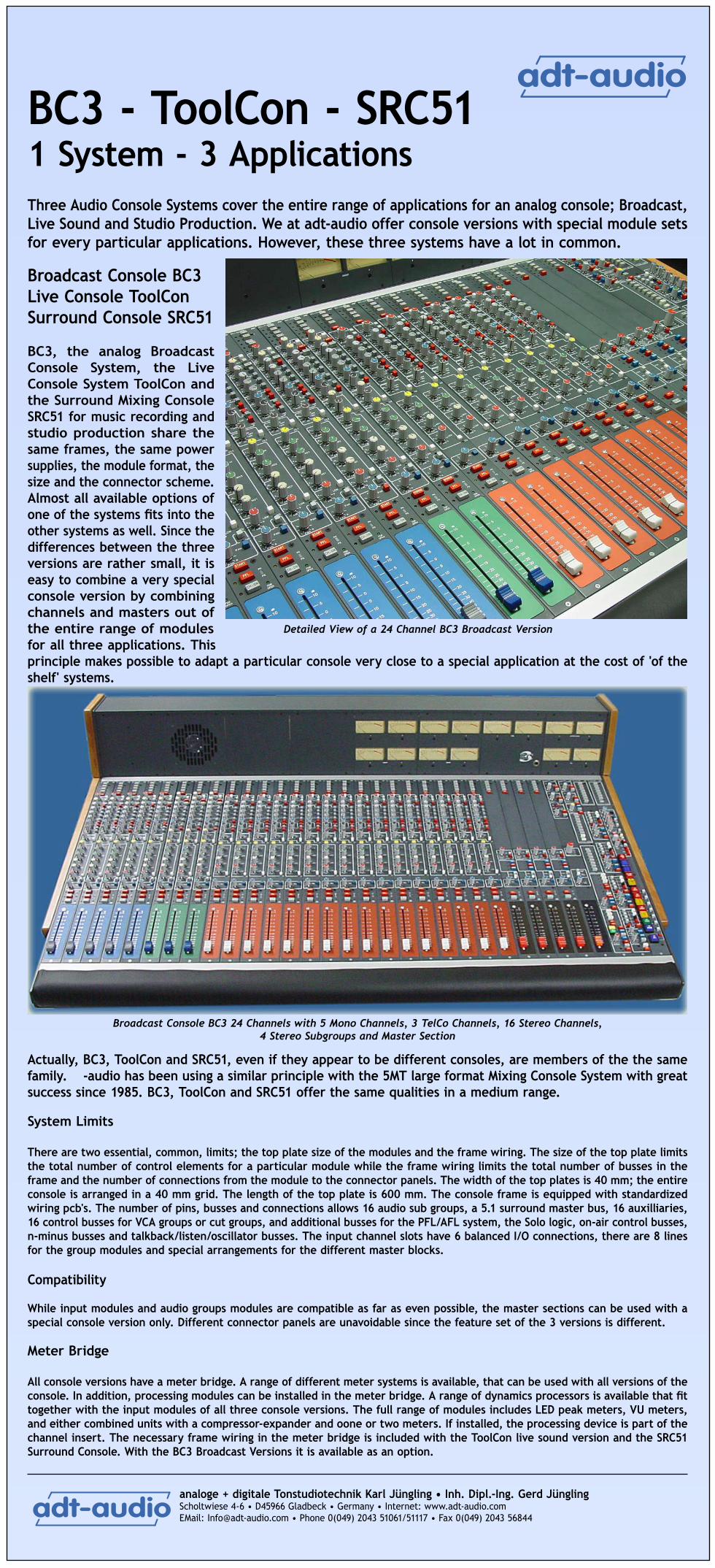
BC3, the analog Broadcast Console System, the Live Console System ToolCon and the Surround Mixing Console SRC51 for music recording and studio production share the same frames, the same power supplies, the module format, the size and the connector scheme. Almost all available options of one of the systems fits into the other systems as well. Since the differences between the three versions are rather small, it is easy to combine a very special console version by combining channels and masters out of the entire range of modules for all three applications. This principle makes possible to adapt a particular console very close to a special application at the cost of 'of the shelf' systems.
Actually, BC3, ToolCon and SRC51, even if they appear to be different consoles, are members of the the same family. -audio has been using a similar principle with the 5MT large format Mixing Console System with great success since 1985. BC3, ToolCon and SRC51 offer the same qualities in a medium range. System Limits
There are two essential, common, limits; the top plate size of the modules and the frame wiring. The size of the top plate limits the total number of control elements for a particular module while the frame wiring limits the total number of busses in the frame and the number of connections from the module to the connector panels. The width of the top plates is 40 mm; the entire console is arranged in a 40 mm grid. The length of the top plate is 600 mm. The console frame is equipped with standardized wiring pcb's. The number of pins, busses and connections allows 16 audio sub groups, a 5.1 surround master bus, 16 auxilliaries, 16 control busses for VCA groups or cut groups, and additional busses for the PFL/AFL system, the Solo logic, on-air control busses, n-minus busses and talkback/listen/oscillator busses. The input channel slots have 6 balanced I/O connections, there are 8 lines for the group modules and special arrangements for the different master blocks.
Compatibility
While input modules and audio groups modules are compatible as far as even possible, the master sections can be used with a special console version only. Different connector panels are unavoidable since the feature set of the 3 versions is different.
Meter Bridge
All console versions have a meter bridge. A range of different meter systems is available, that can be used with all versions of the console. In addition, processing modules can be installed in the meter bridge. A range of dynamics processors is available that fit together with the input modules of all three console versions. The full range of modules includes LED peak meters, VU meters, and either combined units with a compressor-expander and oone or two meters. If installed, the processing device is part of the channel insert. The necessary frame wiring in the meter bridge is included with the ToolCon live sound version and the SRC51 Surround Console. With the BC3 Broadcast Versions it is available as an option.
Detailed View of a 24 Channel BC3 Broadcast Version
Broadcast Console BC3 24 Channels with 5 Mono Channels, 3 TelCo Channels, 16 Stereo Channels, 4 Stereo Subgroups and Master Section

analoge + digitale Tonstudiotechnik Karl Jüngling • Inh. Dipl.-Ing. Gerd JünglingScholtwiese 4-6 • D45966 Gladbeck • Germany • Internet: www.adt-audio.com EMail: [email protected] • Phone 0(049) 2043 51061/51117 • Fax 0(049) 2043 56844
���������
���������
Frame Size
The smallest size for a frame is a 11 slot, rack-mounted frame. This version can be used with up to 8 channels and a basic master section. In principle, sub groups would be possible as well, but it does not make sense to configure a console with 4 input channel and 4 groups - unless you really want us to do it.
The largest frames have 76 module slots that can be used for a 64 input + 8 stereo groups + master section (4 slots) console. Any other combination of modules is possible, of course. Such a frame has an overall width of 3140m includung wooden side panels. The inner width is 3,040 mm, a module slot is 40 mm wide. The top plates are made of 4.5 mm alumium alloy, grinded, brushed and black anodized. The lettering is silk screen printed in white color.
Frame Arrangements
The frame is divided in blocks of 4 modules. Frame are available for any number of modules that can be divided by four up to a total of 76 modules. In addition, a special, rack-mount frame with 11 slots is available. The subdivision in blocks of 4 modules makes possible to configure any frame for a number of channels that can be divided by four. The master section is always a 4 channel block, and one or two 4 channel blocks of audio groups can be installed. To determine the overall width of a console, multiply the number of module slots by 40 mm and add 10 mm for the alumium side panels. Additional wooden fairing plates can be installed. If this option is installed, please add 50 or 70 mm, depending on the thickness of the wood panels. In addition, it is possible to mount a bracket that allows easy integration of a frame in a table or a flight case. This is an alumium gusset, 60 by 40 mm. Please add 80 mm for this option. The drawing shows the top view of a ToolCon Console with 20 input channels, 8 stereo groups and a 4 slot wide master section as an example.
The arrangement in the console's frame is free; however, subgroups and master section require different wiring pcb's. You can specify any arrangement of the position of audio groups and master section in the frame, as long as you make your arrangements in blocks of 4 modules. Group slots are compatible with every group modules of the particular series and input channel slots are compatible with any type of mono or stereo input module and for matrix modules as well. However, the master section is adapted to the special master modules, since these modules have different connector schemes. Power Supply
The power supply unit is a separate device. A range of power supply units is available that cover the entire range of possible console constellations. Fail safe power supply is possible for all versions.

analoge + digitale Tonstudiotechnik Karl Jüngling • Inh. Dipl.-Ing. Gerd JünglingScholtwiese 4-6 • D45966 Gladbeck • Germany • Internet: www.adt-audio.com EMail: [email protected] • Phone 0(049) 2043 51061/51117 • Fax 0(049) 2043 56844
���������
���������
The ToolCon Live ConsoleThe ToolCon System is the Live Sound version of the BC3 console family. A full range of modules makes possible to configure almost any kind of live console and to adapt the particular system to the requirements very well. The consoles can be delivered with the normal frames, with flight cases for use on tour and with an additional floor stand for the fixed installation in a venue. Frames with patchbay are possible.
ToolCon offers 2 different input module versions, an additional stereo input module, a stereo group module, which can be used as dual mono groups as well, an optional matrix module and the master section with the main master module and the monitor module.
The special construction of the console's meter bridge allows to install additional dynamics processors that expand the processing section of the channels. These modules are included in the channel insert; upgrade with dynamics sections is possible at any time.
The picture show a view of the groups and masters section of aToolCon Live Console. From left to right: Standard Input Module TKI2, 8 Group Modules, Mix Master Module, Monitor Module,
2 Matrix Modules, 2 Stereo Channels, 2 Input Modules for external Pre Amps and Processing TKI1
ToolCon - Basic Features:
Stereo Master with additional Mono or Center Output8 Stereo or 16 Mono Groups12 or 18 Aux Sends depending on Input Channel Version, 10 or 16 x mono and 1 x stereo, 8 VCA Groups, 8 additional Cut Groups, with Module TKI1, 4 VCA Grand Master GroupsMaster Cut Groupcomfortable Solo system with different operation modes
The ToolKit Input Channel TKI1
Besides the standard input modules, it is possible to install a special input channel, that is designed for the use with external input amplifiers and an external processing section. adt-audio's input channel strip ToolKit is a unit that is best suited for this channel version, since it includes a very high quality, complete, pre amplifier and processing section. ToolKit is available in a 1U high, rack-mounted housing. Another version of the ToolKit Channel Strip uses a top plate with vertical lettering. A harness that makes possible to install ToolKit units above the input channels is available. Using this input channels offers a different sort of approach to a live console system. All preamplifiers and processors are rack-mounted gear. They are adjusted during the sound check and rehearsal session. All controls that are needed for the show are installed in the modules of the console. The console is more a comfortable distribution system than a conventional console. This division has the great advantage that the console remains small and compact, because it only contains sends, routing, faders and their belonging control elements and master functions. All other equipment is rack-mounted and can be arranged and wired in any appropriate way. If you consider what happens with the installation of a 'normal' console it is obvious that this principle is advantegous.
Nevertheless, with the ToolCon Live Console, it is possible to mix any number of the different channel versions in one console. You can use some ToolKit Channels in combination with external channel strips for the very important signals and add many 'normal' input channels.All input channel types can be mixed with not restrictions.
Stereo Groups and Matrix Channels
Even though the ToolCon system is designed for 8 stereo groups, that can also be used as 16 mono groups, it is possible to configure a console for 4 stereo / 8 mono groups only. However, versions with 8 groups have only 4 VCA Groups and 8 mono aux sends instead of 12. With these versions, the VCA grand masters can be used as VCA Group 5 to 8. Alternatively it is possible to assign 4 Cut Groups to these VCA group busses. The configuration of these features is easy; a couple of internal connection have to be changed.
The dual mono matrix module fits into a normal channel slot. The 16 audio groups, 4 aux sends and an additional, external input are available on the matrix. Any number of matrix modules can be installed; however the console is fully functional if no matrix is installed as well.

analoge + digitale Tonstudiotechnik Karl Jüngling • Inh. Dipl.-Ing. Gerd JünglingScholtwiese 4-6 • D45966 Gladbeck • Germany • Internet: www.adt-audio.com EMail: [email protected] • Phone 0(049) 2043 51061/51117 • Fax 0(049) 2043 56844
���������
���������
Modules for the ToolCon Meter BridgeA range of modules is available that can be installed in the console's meter bridge. Besides LED peakmeters in mono and stereo versions, there a dynamic sections and combined modules with a compressor - expander and one or two LED meters. While the LED peakmeters can be used with all channel modules, the dynamics modules can be used with the standard mono input module TK-I2. If such a module is installed, the dynamics section is part of the channel insert. If the dynamics unit is pre or post the external insert, is determined by Jumpers on the particular module. With the combined modules, the meter can read a different signal as the meter that is installed in the module itself. With the group modules and the matrix channels a meter status function can switch all meters in parallel.
TKC-DNCompressor - Noise-Gate Dynamics Processor
The TKC-DN combines a versatile compressor section with a noise gate with high-pass and low-pass filters. Noise gate and compressors operate totally independent.
The Compressor Section has a full set of controls, Threshold from -32 to +16 dB, Ratio from 1:1 to 1:20 (Limiter Mode), Release time from 0.1 to 3 sec and a very wide attack range from .1 to 30 ms. The KNEE control makes possible a smooth transition from the unregulated to the regulated level range from 0 dB (hard) to 6 dB (soft). The CREST switch changes the characteristics of the rectifier from peak mode (1) to RMS mode (8). Position 2 is a medium value. The envelope function reduces low frequency distortion when short release times are used. A LED chain with 5 LED'S indicates the gain reduction of the compressor.
The noise gate is optimized for very fast attack time. A full set of controls is installed. Threshold from -40 to +15 dB, Range that determines the attenuation with gate closed from 0 dB to -70 dB. Attack, Release and Hold time can be controlled independently. A high-pass, low-pass filter section can be inserted by the FILT switch.
TKC-CCompressor - Expander Dynamics Processor
The TKC-C is a Compressor Expander section that offers a full set of controls for the compressor section and an effective expander. The Compressor Section has a Threshold control from -32 to +18 dB, Ratio from 1:1 to 1:20 (Limiter Mode), Release time from 0.1 to 3 sec and a very wide range of the attack time from .1 30 ms. The compressor operates in peak mode, but the RMS switch makes possible to switch over to RMS operation. With RMS mode, the minium attack time is limited to 5 ms. The Autogain section controls the make up gain precisely. An analog computation circuit regulates the output gain in accordance to the settings of the threshold, ratio, and attack controls. For Limiter operations it is possible to disable the autogain function.
The expander has a threshold control with a range from -10 dB to -50 dB. Th ratio is controlled by an expontial circuit that increases the ratio below the threshold to maintain effective suppression of noise. The attack time is fast while the release time is modulated by signal structure. A LED chain displays the gain reduction of both the compressor and expander.
LED PeakmetersThe high resolution peak meters with 40 LED's have a display range from +15 dB to -40 dB. The attack time is below 1ms; the release time is linearized to 1.5 sec per 20 dB. The mono unit can be used with all mono channels and with the stereo channel, that has a matrix output for the meter, while the stereo unit can be used with the group, master, monitor and matrix modules.
Dynamics with LED PeakmetersThese two modules combine the TKC-CE Dynamics Processor with one or two LED meters. The meters have 20 LED's, the range is from +18 dB to -40 dB. The attack time is below 1 ms and the release time is 1.5 sec per 20 db. The meter signal is determined by jumpers on the input channel. These units can be used with the standard input channel TKC-I2.

analoge + digitale Tonstudiotechnik Karl Jüngling • Inh. Dipl.-Ing. Gerd JünglingScholtwiese 4-6 • D45966 Gladbeck • Germany • Internet: www.adt-audio.com EMail: [email protected] • Phone 0(049) 2043 51061/51117 • Fax 0(049) 2043 56844
���������
���������
The ToolCon Input ModulesThere are two different mono input channel versions and a stereo input channel for the ToolCon Live Console System. All input modules fit in each channel slot and use the same connector panels. The two mono modules have a different feature set. While the standard input channel TKC-I2 is a conventional channel with mic preamp and EQ, that can be completed by additional dynamics units that can be installed in the meterbridge, the TKC-I1 is a distribution channel for the combination with external pre amps and processors.
TKC-I2
Standard Mono Input Channel
The TKC-I2, mono input module is the basic input module of the ToolCon Live Console System. It includes a sophisticated, pristine sounding, transformer balanced mic-preamp, 10 send, that can be routed into 12 busses, sweep type high-pass and low pass filters and a versatile 4 band EQ with 2 fully parametric mid band and a HI- and Low EQ with switched characteristics. Besides the standard components, like fader, Cut, Solo and Meter, 8 VCA groups and an additional Cut Group can be assigned by independent switches.
The input section of the TKC-I2 defaults to the microphone input, which is implemented transformer balanced and floated with an input impedance of at least 2 kOhms. The CMRR of the oversized input transformer, brand Haufe, Germany, is at least 70 dB @ 15 kHz. 48 V phantom power can be applied by the P48 switch. A passive input pad pre transformer makes possible to handle line levels up to + 26 dBu @ 40 Hz with the mic input. The gain control ranges from 25 to 70 dB, without pad. The excellent noise performance of the mic preamp offers low noise values not only with high gain settings. At 70 dB the noise figure is below 1.5 dB. With 40 dB gain, the noise figure still remains below 3 dB. The additional Line Input is electronically balanced and has an input impedance of more than 10 kOhms. It can handle levels of + 28 dBu. The CMRR is better than 50 dB @ 15 kHz. The independent gain control has a range of +/- 20 dB with center detent at 0 dB. The phase reversal switch operates on both the mic and line inputs.
The processing section of the module includes the high-pass, low-pass filter section, the 4 band equalizer and a switched fully buffered, balanced, insert section. All sections have own bypass switches. If no processor is active, the output of the input section drives the channel fader's input directly. All audio switches in the entire signal path of the module are either gold plated pushbutton switches or gold plated relays.
The Filter section contains a high-pass filter with a sweep range from OFF (below 20 Hz) to 600 Hz. The low pass filter has a sweep range from OFF (above 20 kHz) to 2 kHz. Both filters are of the 'maximum flat' type. The steep rate is 12 dB/oct.
The 4 band Equalizer combines two fully parametric mid bands, based on the pristine sounding, active 'Vienna Robinson Bridge' principle with a bell type Low-EQ with selectable center frequencies and a HI EQ that can be used in shelving or bell mode. All bands have a very high boost/cut control range of +/- 20 dB with center detent at 0 dB. The range of the Q factor controls of the mid bands reaches from more than 3 octaves to less than a third. The sweep ranges are from 40 Hz to 4 kHz for the low mid band and from 200 Hz to 18 kHz for the high mid band. The wide overlapping ranges and the total frequency ranges that covers the usable range of the audio band makes these mid EQ's very effective for soft tone shading as well as drastic tonal surgery, while the Hi and Low bands allow the commonly necessary correction in the high and low frequency range in a very effective and fast way. The low EQ is implemented as soft bell. In difference to a shelving low filter, the soft bell avoids the boost of subsonic frequencies. It is not necessary to use the high-pass filter with this low EQ version, however, the center frequencies of 60 Hz or 100 Hz and the adapted Q factor offer the results that you are used to get with a shelving filter and an additional high-pass that limits the low frequency with a performance that is much better, since the phase shift of the bell filter maintains phase linearity that is crucial for an natural sounding, clean, bass. The center frequency is determined by a switch. It defaults to 60 Hz and can be switched to 100 Hz. The HI EQ is a very soft, natural sounding, shelving filter with an edge frequency far above 20 kHz that produces silky high frequency sounds. With the 8 kHz switch pressed the characteristic is a very soft bell with a maximum at 8 kHz.
The insert section is post EQ unless the PRE switches is locked that moves this section pre EQ, post filters. The insert output is always alvailable on the connector panel. The insert return is switched into the channel's signal path when INS ist pressed. Both the insert input and output are electronically balanced and fully buffered. The insert level equals the line level of 0 dB, which can be + 6 dBu or + 4 dBV, depending on your specification. Like all line level inputs and outputs, the insert I/O can handle levels of +28 dBu. The insert connectors on the panel are 1/4", gold plated, high pressure, TRS jacks, brand Neutrik. Insert input and output are half normalized.
If a dynamic section is installed in the console's meter bridge, it becomes part of the insert chain. Jumpers on the dynamics module determine, if the unit is installed in the path from the channel's insert output to the connector panel or in the path from the connector panel to the insert input of the module. However, with both settings, the insert switch must be pressed.
Parallel to the input of the channel fader, which is acutally a high quality VCA, brand THAT, is the PRE send of the sends, the SOLO tap and the channel meter in its default setting. The VCA is controlled by a precision, 100 mm VCA-law, conductive plastic fader, Brand Ko-On. P&G faders are also available, please ask. The fader output drives the pan section, the sends in post position, the channel output and the group and mix routing matrix.
8 VCA groups and an additional cut group can be assinged to the VCA by separate switches. Any number of groups can be selected in parallel. With the default setting of the console, the 8 groups are all VCA groups. If the console is equipped with 4 stereo modules, there are only 4 VCA groups available. It depends on your order specification if the group rails 5 to 8 are open, or assinged to the cut groups 1 to 4, or to the VCA grand masters 1 to 4. The Cut Group 0 is in principle a normal cut group; however, it is usually used to mute the entire console but some stereo channels before and after the concert. The GROUP SAFE switch disables all VCA and Cut groups for this channel. A large format 18 by 18 mm, illuminated switched is used for the channel cut that mute the vca and can mute the sends in pre fader mode either. If this function is active or not depends on jumper setting.
The Solo function, that actually is a Pre Fader Listen system makes possible to feed the pre fader signal to the pfl bus. The operation mode depends on the solo master status. See the description of the monitor module for details. The channel meter reads the pre fader signal, but a set of jumpers on the channel's pcb can tap other signals alternatively. The meter reads the peak level with an attack time of less than 1 ms. There are 10 LED's and the display range is from +12 to -15 dB. The 0 dB level can be adjusted by a trimpot.
The panoramic section is a conventional mono to stereo pan with 3 dB attenuation at the center position. The pan pot is switched into the signal path by the PAN switch. The output of the pan pot drives the routing matrix and the mix switch. The group routing is implemented with 8 switches; each of them selects a stereo pair of groups. The pan pot, if inserted, determines the level relation between the odd and even numbered groups.
The TKC-I2 module has 10 sends in total that drive 12 send busses. There are 8 mono aux sends. Each aux send has its own Pre switch. Aux 7 and Aux 8 have additional routing switch that select if these sends feed aux bus 7 or 9 and aux bus 8 or 10. In addition to the pre/post selection, the switch A1-6 Pre Ins makes possible to use the aux sends 1 to 6 in pre position not pre fader but at the insert send. Since the insert can be routed pre or post EQ, many different settings for different applications are possible. The Cue Send is implemented in stereo with level and pan. It is default pre fader and has a post switch. The cue send has its own cut switch and and additional switch, GR9-16, that splits the group routing matrix into two independ selectors. While group 1 to 8 remains in the normal setting, group 9 - 16 are assinged to the output of the cue pan. With this setting it is possible to use up to 8 groups as floating aux sends, if they are not required as 'normal' audio groups.
The channel output is electronically balanced and can handle levels of +28 dBu. An additional pot controls the output level of this output that is fed from the fader output. The Pre switch routs it pre the channel fader and the Inp switch selects the output of the input amplifier, which is important if the channel is used for recording, pre processing.

analoge + digitale Tonstudiotechnik Karl Jüngling • Inh. Dipl.-Ing. Gerd JünglingScholtwiese 4-6 • D45966 Gladbeck • Germany • Internet: www.adt-audio.com EMail: [email protected] • Phone 0(049) 2043 51061/51117 • Fax 0(049) 2043 56844
���������
���������
The ToolCon Stereo ChannelIn addition to the stereo return inputs that are part of the monitor module the stereo channel TKC-IS offers almost the same features as the standard mono channel TKC-I2. Stereo versions of the filter section and the 4 band EQ that is used with the mono channel make the TKC-IS stereo channel a powerful module that can not only be used for effect returns but for stereo keyboards, synthesizers and other instrument with stereo outputs.
TKC-IS
Stereo Input Channel
The TKC-IS, stereo channel completes the range of the ToolCon input modules. Even though 4 simple stereo channels are included with the monitor module that cover the needs to couple another console or to install a CD player or a tape deck, these stereo inputs do not offer any kind of signal processing and they can neither feed the auxilliaries nor the groups. The TKC-IS stereo channel is the right solution if all these features are needed. It offers access to groups and sends and the at a glance it looks just like the standard mono input channel strip. A stereo version of exactly the 4 band EQ of the TKC-I2 input channel is included as well as a a stereo version of the hipass and low-pass filters.
The input section of the TKC-IS stereo channel is an electronically balanced line input with an input impedance of at least 10 kOhms. It can handle levels of +28 dB, like all line inputs and outputs of the entire ToolCon Live Console system. The CMRR is better than 50 dB @ 15 kHz. The stereo gain control has a range of +/- 20 dB with center detent at 0 dB. Two switches make possible to rerout the stereo input channels. L routs the left input channel to both stereo channels of the module, while R routs the right stereo channel to both internal channels. Channel reverse is applied when both L and R switched are pressed at a time. The phase reversal switch operates on the right input channel.
The processing section of the stereo channel is not different from the mono channel TKC-I2. It includes a stereo high-pass, low-pass filter section, the stereo 4 band equalizer and a switched, fully buffered, balanced, stereo insert section. All sections have their own bypass switches. If no processor is active, the outputs of the input amplifiers drive the stereo fader's inputs directly. All audio switches in the entire signal path of the stereo channel are either gold plated pushbutton switches or gold plated relays.
The Stereo Filter section contains a high-pass filter with a sweep range from OFF (below 20 Hz) to 600 Hz. The low pass filter has a sweep range from OFF (above 20 kHz) to 2 kHz. Both filters are of the 'maximum flat' type. The steep rate is 12 dB/oct. The entire Filter section is a stereo version of the filter section of the TKC-I2 mono channel.
The stereo 4 band Equalizer combines two fully parametric mid bands, based on the pristine sounding, active 'Vienna Robinson Bridge' principle with a bell type Low-EQ with selectable center frequencies and a HI EQ that can be used in shelving or bell mode. All bands have a very high boost/cut control range of +/- 20 dB with center detent at 0 dB. The Q factor control range of the mid bands reaches from more than 3 octaves to less than a third. The sweep ranges are from 40 Hz to 4 kHz for the low mid band and from 200 Hz to 18 kHz for the high mid band. The stereo low EQ is implemented as soft bell. The center frequency is determined by a switch. It defaults to 60 Hz and can be switched to 100 Hz. The stereo HI EQ is a very soft, natural sounding, shelving filter with an edge frequency far above 20 kHz that produces silky high frequency sounds. With the 8 kHz switch pressed the characteristic is a very soft bell with a maximum at 8 kHz. Like the filter section, the EQ is a stereo version of exactly that EQ, that is installed in the mono channel.
The insert section of the stereo channel is of course a stereo insert section. In difference to the mono channel, the insert is fixed post EQ. The insert outputs are always alvailable on the connector panel. The insert returns are switched into the channel's signal path when INS ist pressed. Insert inputs and outputs are electronically balanced and fully buffered. The insert level equals the line level of 0 dB. Like all line level inputs and outputs, the stereo insert I/O can handle levels of +28 dBu. The insert connectors on the panel are 1/4", gold plated, TRS jacks, brand Neutrik. Insert input and output are half normalized. For the stereo channel this acutally means that the left insert out is half normalized to the left insert in and the right out is half normalized to the right input, of course.
We do not offer a stereo dynamics section that fits into the meter bridge of the ToolCon live console, but the installation of such a device is possible as far as the frame wiring is concerned. Perhaps we will complete the module range with a stereo version of a compressor in the future. However, mono or stereo peak meters can be installed. The stereo channel can drive mono meters with a matrix that is part of the module or stereo meters, depending on internal jumper setting.
Parallel to the input of the stereo channel fader, which is acutally a pair of high quality VCA's, brand THAT, is the PRE send of the sends, that is converted to mono by a matrix, the SOLO tap and the channel meter in its default setting. The VCA's are controlled by a precision, 100 mm VCA-law, conductive plastic fader, Brand Ko-On. P&G faders are also available, please ask. The fader outputs drive the stereo balance control, the sends in post position via another mono matrix, and the group and mix routing matrix.
8 VCA groups and an additional cut group can be assinged to the VCA's by separate switches. Any number of groups can be selected in parallel. With the default setting of the console, the 8 groups are all VCA groups. This section of the stereo channel is absolutely identical to the mono module TKC-I2. The Cut Group 0 is in principle a normal cut group; however, it is usually used to mute the entire console but some stereo channels before and after the concert. The GROUP SAFE switch disables all VCA and Cut groups for this channel. A large format 18 by 18 mm, illuminated switched is used for the channel cut that mutes the vca's and can mute the sends in pre fader mode either. If this function is active or not depends on jumper setting.
The Solo function, that actually is a Pre Fader Listen system makes possible to feed the pre fader signal to the pfl bus. The operation mode depends on the solo master status. See the description of the monitor module for details. With the stereo channel the PFL bus is fed with a real stereo signal. The entire PFL/Solo system is a stereo system that is driven in mono with all mono sources but in stereo if with all stereo sources. The channel meter reads the pre fader signal, not via a standard mono matrix but in a way, that the peak level of that stereo channel is displayed that has the higher level. A set of jumpers on the channel's pcb can tap other signals alternatively. The meter reads the peak level with an attack time of less than 1 ms. There are 10 LED's and the display range is from +12 to -15 dB. The 0 dB level can be adjusted by a trimpot. The special stereo rectifier section offers a correct measurement of the peak value and not different with phase shifts between the two stereo channels.
The panoramic section is actually a stereo balance control with 0 dB attenuation at the center position. The balance pot is switched into the signal path by the BAL switch. The output of the balance section drives the routing matrix and the mix switch. The group routing is implemented with 8 switches; each of them selects a stereo pair of groups. The balance control, if inserted, determines the level relation between the odd and even numbered groups.
The TKC-IS stereo channel has 10 sends in total. There are 8 mono aux sends. Each aux send has its own Pre switch. Mono matrix stages are included that drive the mono aux sends with a mono signal from the matrix outputs pre and post fader. The Cue Send is implemented in stereo with level and pan. It is default pre fader and has a post switch. The cue send has its own cut switch. Since Cue is a stereo send it is fed with the stereo pre and post fader signals.
The TKC-IS stereo channel is fully compatible with the live console's input module slots. The stereo input left and right use the XLR mic and line input connectors. The normal insert TRS connectors are used for the left channel insert while the tape input, which is not used with the mono channel, and the channel out are used for the right channel insert. A post fader output is not integrated because an additional stereo output would not fit into the standard connector panel. However, it is possible to set up the channel in a different way, that uses the insert output as channel output. With this setting, the insert input is available but the insert output is actually a post fader out.

analoge + digitale Tonstudiotechnik Karl Jüngling • Inh. Dipl.-Ing. Gerd JünglingScholtwiese 4-6 • D45966 Gladbeck • Germany • Internet: www.adt-audio.com EMail: [email protected] • Phone 0(049) 2043 51061/51117 • Fax 0(049) 2043 56844
���������
���������
The ToolCon 'ToolKit' Mono ChannelThe 'ToolKit' Mono Channels offers 16 aux sends, an additional stereo cue send,8 vca groups, 9 cut groups. There is neither a pre amplifier nor a processing section installed. The design of this channel versions is based on a separate, external channel strip that contains the pre amplifers and the processing section.
TKC-I1
Mono Channel for use with an external Pre Amplifiers and Processing Devices
The TKC-I2, mono channel has a different approach to a live console system. Even though the mono channel version can be equipped with all the necessary processing sections, Filters, EQ, Noise-Gate and Compressor, many live sound engineers prefer to have that outboard gear they are accustomed to. With most live consoles, outboard gear is a must for many channels, for the simple reason that the necessary processing sections are not installed in the particular console or that the quality of the installed devices is inappropriate. A complex live sound set ends up in an extensive, external wiring with a lot of external devices, many racks, many multicores and a final system that is unclear and confusing. Do you know which compressor in a 32 U high rack, filled with gear is used for what? Most of the guys do not. The only way to handle a system like that is to set up all pre amps and processing devices during the sound check and leave it as it is during the concert, unless it is inavoidable to change a setting, since there is distortion, overload, noise, or anything else that needs to be changed immediately.
The principle to use a heap of outboard equipment leads to the consideration, that the console channel strip can be reduced to a distribution system. Aux sends, groups, vca and cut groups and the faders and cut switches are the controls that are used during the concert. In principle, any processing equipment can be left out of the console. The major advantage of such a console is that the size can be rather small, since a lot of aux sends and group routing switches do not require that much space on the top plate. The major disadvantage of such a system is the high cost. Even though a console channel that does not contain all pre amps and processing section will be a bit less expensive than a version with everything installed, this savings will not cover the cost for external channel strips, EQ's, compressors and noise gates. Besides, most of the savings will be re-invested in more aux sends, more groups, and more other features. In total, a complete 'all outboard' system is going to be too expensive for many users, because they have to consider the return of investment - and that depends on the limited budgets of most of their customers.
We at adt-audio offer a solution that lets you put together the best of these two worlds so that you can make your own compromise. Besides the standard mono channel, TKC-I2, that includes pre amp, filters, EQ, and, if you like, dynamics processors as well, we offer the mono channel version TKC-I1, that is fully compatible with any input module slot of the ToolCon frame but does not include any pre amplifiers or processing stage. Consequently, this mono channel has a fixed level line input and no insert section but 18 aux sends, 8 vca groups, 9 cut groups and an extended routing matrix with single switches for every group.
ToolKit Channel Strip
The basic idea for this mono channel version came up when we made the input channel strip ToolKit, that is a complete pre amp and processing section, which contains every stage at a very high quality level. Besides the transformer mic preamp, there are high-pass, low-pass filters, a versatile compressor that can be adapted in many ways, a very fast noise gate with it's own filter section with very wide sweep ranges, a 5 band EQ of proven quality that has been used in many input channels of our large format music production consoles and a very fast limiter. After the first tests we have got many reactions like 'this is the ultimate tool for anything', and 'can you guys make a console out of these units?'. Some basic calculations brought us back to earth; however, it is a very good compromise to use some (up to you what number you choose for the word some) of these toolkits with the TKC-I1 mono channels for the very important signals of the mix. The ToolKit channel strip offers anything you need, while the console input channels offers a rich feature set, as far as auxiliaries, groups and all other distribution and control circuits are concerned. 'Some' (see above what this is supposed to mean) of these channels can improve the sound performance of the entire mix a lot. The compatibility of both mono channel versions makes possible to install many 'normal', additional channels; therefore the total cost of the entire systems is still appropriate, depending on your interpretations of the little word 'some'.
For those who understand the meaning of 'some' in the range of 24 or more, we offer a special version of the ToolKit Channel Strip. This version has another top plate with a vertical lettering. Every Toolkit already includes plugs that make possible to use the unit with this special, vertical top plate in a special frame, that can be mounted above the console's channels. If you'de like to know more details about this version, just let us know or give us a call on 0049 2043 51061.
The input of the TKC-I1 mono channel is an electronically balanced line input that can handle levels of + 28 dBu but has no gain control, since this should be part of the external channel strip. The fader section uses a high performance VCA, brand THAT, that is controlled by the local 100 mm, conductive plastic, VCA law fader. 8 VCA groups and 9 cut groups can be assigned to the the channel by separate switches. A Group Safe switch disables the entire group selection. The Solo System is identical to the TKC-I2 mono channel but it uses the same large format, illumniated push button that is used for the cut function.
The meter reads the peak level at the fader input with an attack time of less than 1 ms. There are 10 LED's and the display range is from +12 to -15 dB. The 0 dB level can be adjusted by a trimpot.
The panoramic section is a standard mono to stereo control with an attenuation at the center position of 3 dB. It is inserted into the signal path by the PAN switch. The output of the pan pot drives the routing matrix and the mix switch. The group routing is implemented with 16 switches; each of them selects a single group in mono. The pan pot, if inserted, determines the level relation between the odd and even numbered groups.
The TKC-I1 mono channel has 18 sends in total. There are 16 mono aux sends. Each aux send has its own Pre switch. Internal buffer amplifiers that feed the inputs of the aux sends, maintain a headroom of +28 dBu with every possible constellation. The TKC-I1 module requires 8 stereo group modules, since each group modules contains two aux masters as well. If less than 8 group modules are installed, only a part of the 16 aux send can be used.
The Cue Send is implemented in stereo with level and pan. It is default pre fader and has a post switch. The cue send has its own cut switch.
An electronically balanced, post fader output is available on the connector panel.
The TKC-I1 mono channel is fully compatible with the live console's input module slots. It uses the standard line input (XLR) as input and the channel output TRS jack.
analoge + digitale Tonstudiotechnik Karl Jüngling • Inh. Dipl.-Ing. Gerd JünglingScholtwiese 4-6 • D45966 Gladbeck • Germany • Internet: www.adt-audio.com EMail: [email protected] • Phone 0(049) 2043 51061/51117 • Fax 0(049) 2043 56844
���������
���������
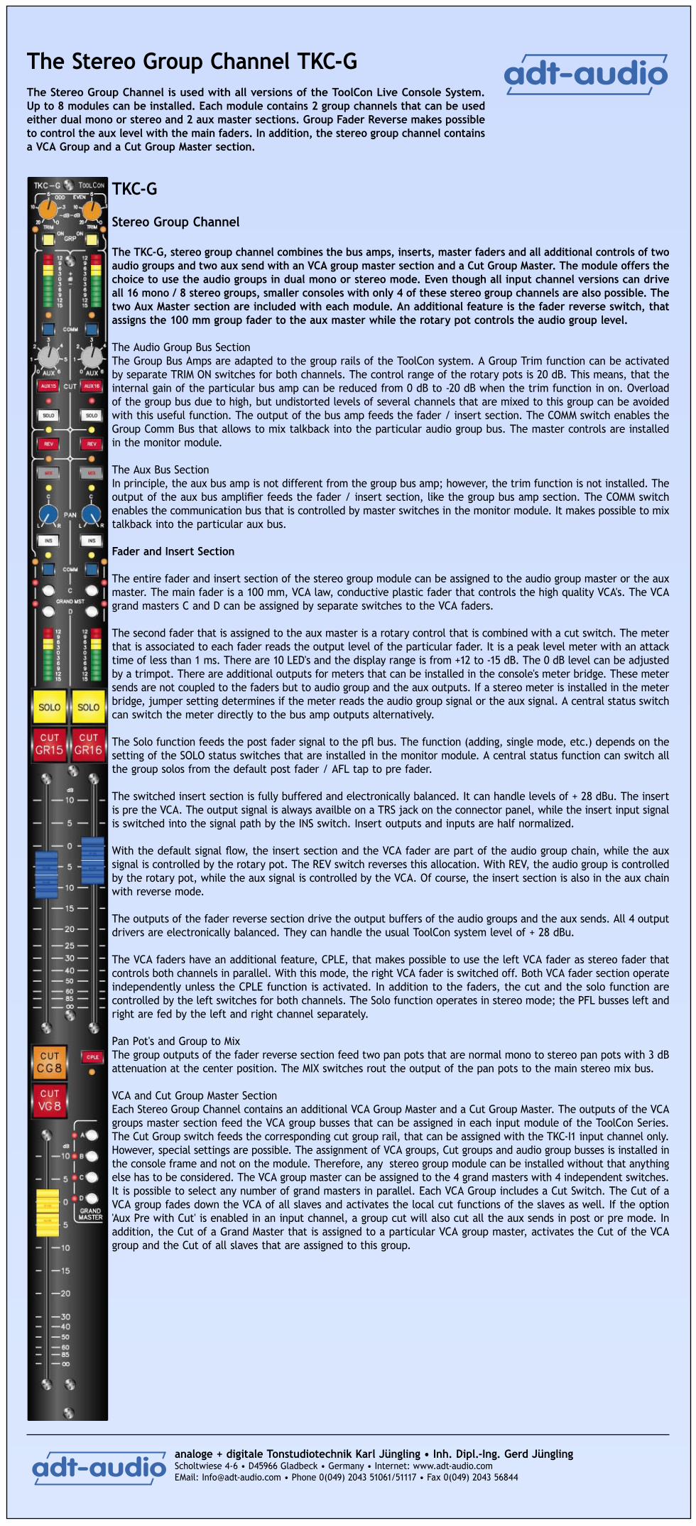
The Stereo Group Channel TKC-GThe Stereo Group Channel is used with all versions of the ToolCon Live Console System. Up to 8 modules can be installed. Each module contains 2 group channels that can be used either dual mono or stereo and 2 aux master sections. Group Fader Reverse makes possible to control the aux level with the main faders. In addition, the stereo group channel contains a VCA Group and a Cut Group Master section.
TKC-G
Stereo Group Channel
The TKC-G, stereo group channel combines the bus amps, inserts, master faders and all additional controls of two audio groups and two aux send with an VCA group master section and a Cut Group Master. The module offers the choice to use the audio groups in dual mono or stereo mode. Even though all input channel versions can drive all 16 mono / 8 stereo groups, smaller consoles with only 4 of these stereo group channels are also possible. The two Aux Master section are included with each module. An additional feature is the fader reverse switch, that assigns the 100 mm group fader to the aux master while the rotary pot controls the audio group level.
The Audio Group Bus SectionThe Group Bus Amps are adapted to the group rails of the ToolCon system. A Group Trim function can be activated by separate TRIM ON switches for both channels. The control range of the rotary pots is 20 dB. This means, that the internal gain of the particular bus amp can be reduced from 0 dB to -20 dB when the trim function in on. Overload of the group bus due to high, but undistorted levels of several channels that are mixed to this group can be avoided with this useful function. The output of the bus amp feeds the fader / insert section. The COMM switch enables the Group Comm Bus that allows to mix talkback into the particular audio group bus. The master controls are installed in the monitor module.
The Aux Bus SectionIn principle, the aux bus amp is not different from the group bus amp; however, the trim function is not installed. The output of the aux bus amplifier feeds the fader / insert section, like the group bus amp section. The COMM switch enables the communication bus that is controlled by master switches in the monitor module. It makes possible to mix talkback into the particular aux bus.
Fader and Insert Section
The entire fader and insert section of the stereo group module can be assigned to the audio group master or the aux master. The main fader is a 100 mm, VCA law, conductive plastic fader that controls the high quality VCA's. The VCA grand masters C and D can be assigned by separate switches to the VCA faders.
The second fader that is assigned to the aux master is a rotary control that is combined with a cut switch. The meter that is associated to each fader reads the output level of the particular fader. It is a peak level meter with an attack time of less than 1 ms. There are 10 LED's and the display range is from +12 to -15 dB. The 0 dB level can be adjusted by a trimpot. There are additional outputs for meters that can be installed in the console's meter bridge. These meter sends are not coupled to the faders but to audio group and the aux outputs. If a stereo meter is installed in the meter bridge, jumper setting determines if the meter reads the audio group signal or the aux signal. A central status switch can switch the meter directly to the bus amp outputs alternatively.
The Solo function feeds the post fader signal to the pfl bus. The function (adding, single mode, etc.) depends on the setting of the SOLO status switches that are installed in the monitor module. A central status function can switch all the group solos from the default post fader / AFL tap to pre fader.
The switched insert section is fully buffered and electronically balanced. It can handle levels of + 28 dBu. The insert is pre the VCA. The output signal is always availble on a TRS jack on the connector panel, while the insert input signal is switched into the signal path by the INS switch. Insert outputs and inputs are half normalized.
With the default signal flow, the insert section and the VCA fader are part of the audio group chain, while the aux signal is controlled by the rotary pot. The REV switch reverses this allocation. With REV, the audio group is controlled by the rotary pot, while the aux signal is controlled by the VCA. Of course, the insert section is also in the aux chain with reverse mode.
The outputs of the fader reverse section drive the output buffers of the audio groups and the aux sends. All 4 output drivers are electronically balanced. They can handle the usual ToolCon system level of + 28 dBu.
The VCA faders have an additional feature, CPLE, that makes possible to use the left VCA fader as stereo fader that controls both channels in parallel. With this mode, the right VCA fader is switched off. Both VCA fader section operate independently unless the CPLE function is activated. In addition to the faders, the cut and the solo function are controlled by the left switches for both channels. The Solo function operates in stereo mode; the PFL busses left and right are fed by the left and right channel separately.
Pan Pot's and Group to MixThe group outputs of the fader reverse section feed two pan pots that are normal mono to stereo pan pots with 3 dB attenuation at the center position. The MIX switches rout the output of the pan pots to the main stereo mix bus.
VCA and Cut Group Master SectionEach Stereo Group Channel contains an additional VCA Group Master and a Cut Group Master. The outputs of the VCA groups master section feed the VCA group busses that can be assigned in each input module of the ToolCon Series. The Cut Group switch feeds the corresponding cut group rail, that can be assigned with the TKC-I1 input channel only. However, special settings are possible. The assignment of VCA groups, Cut groups and audio group busses is installed in the console frame and not on the module. Therefore, any stereo group module can be installed without that anything else has to be considered. The VCA group master can be assigned to the 4 grand masters with 4 independent switches. It is possible to select any number of grand masters in parallel. Each VCA Group includes a Cut Switch. The Cut of a VCA group fades down the VCA of all slaves and activates the local cut functions of the slaves as well. If the option 'Aux Pre with Cut' is enabled in an input channel, a group cut will also cut all the aux sends in post or pre mode. In addition, the Cut of a Grand Master that is assigned to a particular VCA group master, activates the Cut of the VCA group and the Cut of all slaves that are assigned to this group.

analoge + digitale Tonstudiotechnik Karl Jüngling • Inh. Dipl.-Ing. Gerd JünglingScholtwiese 4-6 • D45966 Gladbeck • Germany • Internet: www.adt-audio.com EMail: [email protected] • Phone 0(049) 2043 51061/51117 • Fax 0(049) 2043 56844
���������
���������
The Mix Master Module TKC-MAThe Mix Master Module of the ToolCon Live Console System includes the complete stereo master chain with insert and fader section, an additional mono output that can be used for a dedicated center channel alternatively, a stereo cue master section and a couple of additional functions, like record output, inject input as well as the VCA Grand Master sections 1 and 2. The module must be installed in every ToolCon console.
TKC-MA
Stereo Mix Master Module
The stereo Mix Master chain of the TKC-MA Master Module, stereo mix master channel combines the bus amps, inserts, master faders and all additional controls of the main mix master and the stereo cue send with two VCA grand master fader. The additional mono output that can be used in different modes. Besides there are a record output with independent level control, an stereo inject input, the Cut-All Function and the Cut Group 0 master control as well as two VCA Grand master sections.
The Mix Master Bus SectionThe mix master bus amps are adapted to the group rails of the ToolCon system. A Group Trim function like it is implemented in the group master channels, can be activated by separate TRIM ON switches for both stereo channels. The control range of the rotary pots is 20 dB. This means, that the internal gain of the particular bus amp can be reduced from 0 dB to - 20 dB when the trim function in on. Overload of the mix master bus due to high, but undistorted levels of several channels that are mixed to the master can be avoided with this useful function. There is no COMM switch, but a special talkback line for the mix master. See the description of the monitor module for details. The outputs of the bus amps feed the mix insert section.
The Cut All FunctionAn additional, special, central cut function, CUT ALL makes possible to mute the entire console but not the 4 stereo inputs, that are part of the monitor module. Actually, CUT ALL is not a cut group but a switch that disconnects the main mix bus but not the 4 stereo inputs, that have their own stereo bus and bus amp. This function offers the choice to make sure that before and after the concert the entire console is muted while it is still possible to send a CD or anything else that is connected to the 4 stereo inputs to the speakers. Besides, ToolCon offers an additional way to accomplish this task. If this general setting is not appropriate, the CUT GROUP 0 can be used for a special setup of mutes. Cut All, like Cut Mix and Cut Group 0 are very delicate switches, because they can mute the entire console, depending on the particular set up of the console. To reduce the risk of unintended use, is is possible to block these critical function by an optional 'Concert Mode' switch.
The Inject InputThis is an additional stereo input that drives the main mix bus via a stereo rotary pot when the ON switch is pressed. A non latching Solo switch makes possible to check the inject input signal. It offers the choice to couple another console or to include any other line level stereo signal. Internal jumpering determines if the inject input is muted by CUT ALL or not.
The Mix Insert SectionThe stereo mix insert section is fully buffered. All inputs and outputs are electronically balanced, can handle levels of + 28 dBu and operate at the standard ToolCon 0 dB level. The insert outputs are always available on the connector panel. The insert inputs are switched into the mix master chain when the INS switch is pressed. The output of the mix insert section feeds the master fader and the pre fader mono matrix.
The Mix Master FaderThe master fader is a 100 mm, VCA law, conductive plastic fader that controls the high quality VCA's, brand THAT. The Solo switch operates like all other solo switches in the entire console, but it feeds the pre fader signal to the pfl bus, since the mix output is the default monitor source signal. Cut and Solo use large format, illumniated push buttons The mix master fader is always a stereo fader. In addition, there is a trim control that can be activated by a switch. This rotary pot makes possible to control the level balance of the two stereo channels within a control range of +/- 6 dB. Small level differences between left and right can be compensated. The fader output includes another, post fader, mono matrix.
The Mix Output SectionThe output of the mix fader drives the electronically balanced mix output buffers. Like all outputs of the ToolCon live console system, the mix outputs can handle levels of + 28 dBu into a load of 600 Ohms. A peak meter with 10 LED's reads the output of the mix master chain. Additional, high resolution meters can be installed in the meter bridge as an option.
The Record OutputAn additional output, RECORD, is available, which has a separate, electronically balanced, output driver. A rotary control determines the record output level independently. The ON switch enables this output that can be used for recording or to send the mix output signal to a broadcast van or to another console.
Mono and Center SectionIn addition to the main stereo master, there is a separate mono output that can be used in different modes. The default mode of the mono output is post mix master fader. The FDR switch rerouts the input of the mono chain pre fader. The Center Switch below the mono fader changes the entire function of the mono output. With center pressed, the mono chain operates independent of the stereo mix master. There are different ways to use the center function that is primarily used to drive the center speakers separately. Most of the users prefer to use an aux send, a matrix or an audio group for this task; however, it is possible to use the mono output as well. With center pressed, either the output of an additional bus amp or any of the sixteen groups or 8 of the aux send are switched to the mono fader input. The additional bus amp can be disconnected by a jumper; all other versions require a wire from one of the module connectors to this jumper. Please, let us know which version you prefer; there is no additional cost for this feature. The additional bus amp is connected to a separate 'Center' bus that is used with special module versions only. For all the input modules it is possible to install a center option in two ways that both use a dual concentric pot as main pan pot. While one of the pots still has the normal pan function, the second pot operates like an aux send that is always parallel to the pan pot's input and drives the center bus. This 'Center Send' is always active, if the pan pot is switched on or not. The other version implements a special 3 channel L-C-R pan pot that controls the relation between the three channels in a similar way a surround pan pot does. We consider this version as pointless, because it does not meet the requirements of the use of the center channel in a live console. However, if you want to figure out for yourself if its pointless or useful; it's available.
Cue Master SectionThe bus amp, master fader and the output driver of the stereo send Cue is included in the master module. There is Solo switch and a cut switch; the master fader is a stereo rotary pot. The Comm switch makes possible to enable the Talkback To Aux line for the Cue Send. An additional pair of peak meters reads the cue output levels.
VCA Grand Master and Cut Group 0The Mix Master Module contains two of the four VCA Grand Master sections and the Cut Group Master for the Cut Group 0. The outputs of the VCA group master sections feed four control busses that can be assigned with the VCA group masters and the audio group master faders. Each VCA Grand master includes a cut switch that fades down the slave VCA's and activates the VCA Group Cut function. This means that the CUT of a grand masters activates the cut of the selected group masters and of all the slaves that are assigned to the particular VCA group master. Any VCA Group can also be used as a cut group with the group fader at the 0 dB position.
The Cut Group 0 is a normal cut group, but this group can be assinged to any channel, while the cut group 1 to 8 are avaiable with the TKC-I1, Toolkit mono channel only.

analoge + digitale Tonstudiotechnik Karl Jüngling • Inh. Dipl.-Ing. Gerd JünglingScholtwiese 4-6 • D45966 Gladbeck • Germany • Internet: www.adt-audio.com EMail: [email protected] • Phone 0(049) 2043 51061/51117 • Fax 0(049) 2043 56844
���������
���������
The Monitor Controller TKC-MAThe Monitor Controller of the ToolCon Live Console System combines the complete monitor section, the console's Solo System, a stereo pair of high resolution meters, the Talkback section and the central status functions. In addition, there are 4 stereo line inputs and the VCA Grand Master sections 3 and 4. Of course, a headphone amplifier is integrated as well.
TKC-MO
Monitor Controller Besides the monitor controller section this modules contains every additional monitor and control function that is necessary for the operation of the entire live console.
The MetersThe main stereo meter reads the output of the source selector. If SOLO SAFE is not pressed, an active Solo in the console switches the meters automatically to the calibrated output of the solo bus amps. The meter reads the peak value with an attack time of less than 1 ms and a release time of 1.5 s per 20 dB. There are 20 LED's that cover the display range from +21 dB to -36 dB.
The Stereo Line InputsFour simple stereo line level inputs are part of the monitor controller TKC-MO. These inputs can be used as effect returns or for any other purpose. These inputs are not affected by the central cut function, CUT ALL. This offers the choice to make sure that before and after the concert the entire console is muted while it is still possible to send a CD or anything else that is connected to the 4 stereo inputs to the speakers. Each input is electronically balanced, it has a rotary stereo fader and a rotary balance control with a center attenuation of 0 dB, a non latching Solo switch and a TO MIX switch.
The Talkback SectionAn internal electret type condensator microphone can be mixed with an external, line level talkback signal. The gain control of the internal talkback microphone covers the range from 20 to 50 dB. The level control of the external input covers the range from off to + 6 dB. The INT OFF switch makes possible to cut off the internal microphone. The output of the talkback mixer is available on the connector panel. In addition it drives two internal talkback rails, TALK AUX and TALK GROUP, which are enabled by separate, large format pushbuttons. The COMM switches in the group master module determine if talkback is mixed to a particular aux send or sub group. It is possible to use the talkback routing system for the distribution of an external oscillator alternatively. An electronically balanced input for the oscillator is available on the connector panel. The C/O OSC switches over to this input. In this mode, the talkback system is disabled.
The Status SectionThere are two status switches, METER PRE and CONCERT MODE. Meter Pre switches all external group meters that can be installed in the meter bridge from the default post fader tap to pre fader. CONCERT MODE blocks the very delicate functions CUT ALL, CUT-GR 0 and CUT MIX.
The Solo SystemThe audio chain of the Solosystem is rather simple, because its a simple stereo bus amp. The output of this bus amp can be switched to the meters, the speaker outputs and/or the headphones, depending on the setup of the particular section. In addition a stereo meter can be installed in the meterbridge, which reads the solo signal only. Of course, Solo is availbale on the connector panel as well. The solo status section controls and displays the operation of the local solo switches and the state of the entire solo system. The default operation mode is SINGLE, which means that only one Solo can be active at a time. When another Solo switch is pressed, the previously active Solo is resetted automatically. There are a few exclusive solo switches, that override this mode. These switches are non latched and only active as long as they are pressed. The Solo's of the 4 stereo inputs are implemented in this way. If SOLO ADD is pressed, any number of Solo switches can be active at the same time. All active Solo signals are mixed. Solo operates in latched mode always. The first press activates the particular Solo, the second press resets it. The Solo CLR resets all active Solos, indepent of the mode. The lamp of the SOLO CLR switch indicates that the console is in Solo mode. The SOLO PRE switch makes possible to switch the AFL Solos of the group masters and aux masters to PFL mode.
The Source SelectorIn main source selector determines the signal that feeds the speaker output section or the monitor controller, MON, and the headphone amplifiers in default operation mode. The selector is a mutual releasing switch block of 5 switches. In addition to the mix master output, 4 external sources can be selected. All external inputs are electronically balanced. The output of the source selector drives the main meters if no solo is active. See the meter description for details.
Delay InsertFor some reasons, (open air concert, huge venues) it might be desireable or even necessary to install a delay line in the monitor chain. The TKC-MO monitor controller offers an insert point that makes possible to install an external delay line on the connector panel and switch the output of this delay line into the monitor signal chain with the DELAY switch.
The Speaker Output SectionBoth the speaker and the headphone output are driven by the output of the source selector. However, Solo cann be handled differently for speakers and phones. The output signal of the delay insert feeds the mono matrix that operates with 6 dB attenuation (3 dB is possible by jumper setting). The MNO switch actives this matrix. A stereo balance control that makes possible to shift the center position of the stereo system can be activate by the BAL swtich. The L and R switch make possible to listen to single stereo channels. L switches off the right channel while R switches off the left channel. Both switches, pressed at a time reverse the two stereo channels. The output of this section drives the headphone amplifier directly. The speaker section has its own SOLO switch that enables the auto switch over function for the speaker outputs when this switch is pressed. A rotary pot controls the level of the solo signal independently. The DIM switch attenuates the speaker signal by 12 dB (other values are possible). DIM is automatically activated with any Talkback. The output of the rotary volume control drives the electronically balanced output buffers, the Cut switch that mutes all speakers and the ALT switch that allows the selection of an alternate speaker set. The outputs of the speaker section can be used for a second headphone as well.
The Headphone Output SectionThe input of the headphone amplifier is driven by the output of the control section, post the balance control, the mono switch and the L and R switch set. The SOLO switch actives the automatic switch over function. If this switch is pressed, an active Solo overrides the default source select and switches the headphones to the solo bus. The level can be controlled independently by a separate rotary pot. A LED indicates, that solo is active. The external input makes possible to inject an external stereo signal directly into the headphone. This signal that is usually the output of a communication system, is mixed with the normal source signal that is either the output of the source selector or the solo signal. The external input is electronically balanced; the level is controlled by a rotary pot. The EXT switch enables this input. An additional switch, SOURCE makes possible to disable the signal from the source selector. If this switch is pressed, only the external input, if activated, and the solo signal, if activated, feed the headphone amplifier. Besides the volume control pot there is a Cut switch that mutes the headphone output. The output jack is mounted in the console's meter bridge; however, we made the experience that everybody has a different opinion about the location of the headphone jack. Please, let us know where you want to have it installed.
VCA Grand MasterThe Monitor Controller contains two of the four VCA Grand Master sections. The outputs of the VCA group master sections feed four control busses that can be assigned with the VCA group masters and the audio group master faders. Each VCA Grand master includes a cut switch that fades down the slave VCA's and activates the VCA Group Cut function. This means that the CUT of a grand masters activates the cut of the selected group masters and of all the slaves that are assigned to the particular VCA group master. Any VCA Group can also be used as a cut group with the group fader at the 0 dB position.

analoge + digitale Tonstudiotechnik Karl Jüngling • Inh. Dipl.-Ing. Gerd JünglingScholtwiese 4-6 • D45966 Gladbeck • Germany • Internet: www.adt-audio.com EMail: [email protected] • Phone 0(049) 2043 51061/51117 • Fax 0(049) 2043 56844
���������
���������
The Matrix Channel TKC-MTThe Matrix Channel completes the module pallet of the ToolCon Live Console System. It fits into any channel slot of the console. Any number of matrix modules can be installed in a console. Each Matrix Channel contains two complete matrix chains with 23 inputs and a master ouput. In addition to aux send outputs, subgroup and mix outputs there is an external input available.
TKC-MT
Matrix ChannelThe Matrix Channel can be installed in each channel slot of a ToolCon Live Console. It is not necessarily part of every console. Any number of matrix modules can be installed and it is up to you where these modules are installed.
Each matrix channel contains 2 independent mono matrix chains. Each chain is a complete 23 in 1 mixer with switched insert section, master fader and meter.
The InputsThere is one external input that is implemented electronically balanced. It makes possible to inject any external, line level signal. The other 22 inputs of each matrix chain are assigned to the stereo left and right outputs, the 16 group outputs and the outputs of the aux sends 5 to 8. The COMM switch enables the Talkback to Aux bus and makes possible to mix talkback signal into the matrix chain.
InsertThe outputs of the bus amps drive the switched insert sections. Insert inputs and outputs are available on half normalized TRS jacks on the connector panel. Both outputs and inputs are fully buffered and electronically balanced. They can handle levels of + 28 dBu. The outputs are always available on the connector panel, the inputs are switched into the matrix signal chain with the INS switch. The insert section is always pre the matrix master fader.
Matrix Master Faders, Cut, Solo and MetersThe matrix master fader is a 100 mm, conductive plastic, VCA law fader. The audio signal is controlled by a high quality VCA. In addition to the fader that has a maximum gain of 10 dB, there is are a large format, illuminated Cut switch that mutes the entire matrix output and a Solo switch that makes possible to control the matrix signal with the console's Solo System. The meters read the matrix output levels in peak mode with an attack time that is shorter than 1 ms and a release time of 1.5 s per 20 dB. The display range of the meter is +12 dB to -15 dB.
OutputThe matrix output is electronically balanced and can handle levels of + 28 dBu into a 600 Ohm load.