Baumann™ 84000 Series Sanitary Regulators · 1 84000 Series Regulators Bulletin 84.1.REG:BTN...
12
1 84000 Series Regulators Bulletin 84.1.REG:BTN October 2005 Rev 1 Baumann ™ 84000 Series Sanitary Regulators Pressure regulation for your sanitary process. The Baumann™ 84000 series of sanitary regulators are designed specifically for those applications requiring precise pressure regulation in a sanitary environment. Polished, stainless steel body and internal components ensure efficient cleaning and sanitizing giving you confidence that your processing environment maintains the highest purity. All of the 84000 series regulators provide self-draining design and zero dead leg options. Figure 1. 84000BR Series Back Pressure Regulator Figure 2. 84000ABR Series Air Loaded Back Pressure Regulator Figure 3. 84000RR Series Sanitary Pressure Reducing Regulator FEATURES: ■ Compact and light weight design reduces installed piping costs. ■ Tri-Clamp end connections standard with optional welded end connections. ■ Electropolished internal surfaces: standard < 35 Ra Microinch; optional < 20 Ra Microinch. ■ Quick-Disconnect bonnet. ■ Sensing diaphragm meets FDA 21 CFR 177 and USP Class VI. ■ Self-draining design for effective Clean-in-place (CIP) and Sanitize-in-place (SIP).
Transcript of Baumann™ 84000 Series Sanitary Regulators · 1 84000 Series Regulators Bulletin 84.1.REG:BTN...

1
84000 Series RegulatorsBulletin84.1.REG:BTNOctober 2005 Rev 1
Baumann™ 84000 Series Sanitary RegulatorsPressure regulation for your sanitary process.
The Baumann™ 84000 series of sanitary regulators are designed specifically for those applications requiring precise pressure regulation in a sanitary environment.
Polished, stainless steel body and internal components ensure efficient cleaning and sanitizing giving you confidence that your processing environment maintains the highest purity.
All of the 84000 series regulators provide self-draining design and zero dead leg options.
Figure 1. 84000BR Series Back Pressure Regulator
Figure 2. 84000ABR Series Air LoadedBack Pressure Regulator
Figure 3. 84000RR Series Sanitary Pressure Reducing Regulator
FEATURES:
■ Compact and light weight design reduces installed piping costs.
■ Tri-Clamp end connections standard with optional welded end connections.
■ Electropolished internal surfaces: standard < 35 Ra Microinch; optional < 20 Ra Microinch.
■ Quick-Disconnect bonnet.
■ Sensing diaphragm meets FDA 21 CFR 177 and USP Class VI.
■ Self-draining design for effective Clean-in-place (CIP) and Sanitize-in-place (SIP).
2
Bulletin84.1.REG:BTN
October 2005 Rev 184000 Series Regulators
3
84000 Series RegulatorsBulletin84.1.REG:BTNOctober 2005 Rev 1
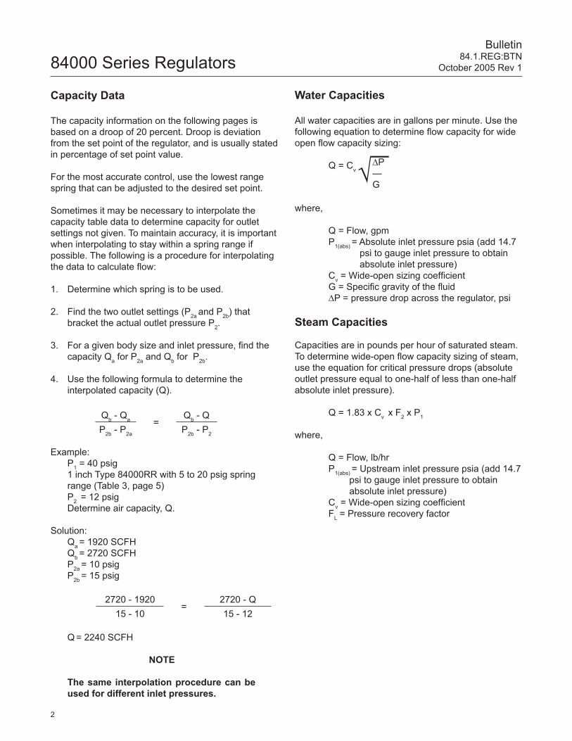
Capacity Data
The capacity information on the following pages is based on a droop of 20 percent. Droop is deviation from the set point of the regulator, and is usually stated in percentage of set point value.
For the most accurate control, use the lowest range spring that can be adjusted to the desired set point.
Sometimes it may be necessary to interpolate the capacity table data to determine capacity for outlet settings not given. To maintain accuracy, it is important when interpolating to stay within a spring range if possible. The following is a procedure for interpolating the data to calculate flow:
1. Determine which spring is to be used.
2. Find the two outlet settings (P2a and P2b) that bracket the actual outlet pressure P2.
3. For a given body size and inlet pressure, find the capacity Qa for P2a and Qb for P2b.
4. Use the following formula to determine the interpolated capacity (Q).
Example: P1 = 40 psig 1 inch Type 84000RR with 5 to 20 psig spring
range (Table 3, page 5) P2 = 12 psig Determine air capacity, Q.
Solution: Qa = 1920 SCFH Qb = 2720 SCFH P2a = 10 psig P2b = 15 psig
Q = 2240 SCFH
NOTE
The same interpolation procedure can be used for different inlet pressures.
Qb - Qa =Qb - Q
P2b - P2a P2b - P2
2720 - 1920=
2720 - Q15 - 10 15 - 12
Water Capacities
All water capacities are in gallons per minute. Use the following equation to determine flow capacity for wide open flow capacity sizing:
Q = Cv
where,
Q = Flow, gpm P1(abs) = Absolute inlet pressure psia (add 14.7 psi to gauge inlet pressure to obtain absolute inlet pressure) Cv = Wide-open sizing coefficient G = Specific gravity of the fluid ∆P = pressure drop across the regulator, psi
Steam Capacities
Capacities are in pounds per hour of saturated steam. To determine wide-open flow capacity sizing of steam,use the equation for critical pressure drops (absolute outlet pressure equal to one-half of less than one-half absolute inlet pressure).
Q = 1.83 x Cv x F2 x P1
where,
Q = Flow, lb/hr P1(abs) = Upstream inlet pressure psia (add 14.7 psi to gauge inlet pressure to obtain absolute inlet pressure) Cv = Wide-open sizing coefficient FL = Pressure recovery factor
√—∆P—G

2
Bulletin84.1.REG:BTN
October 2005 Rev 184000 Series Regulators
3
84000 Series RegulatorsBulletin84.1.REG:BTNOctober 2005 Rev 1
Air Capacities Regulating capacities at selected pressures and outlet pressure flows are given in Table 3, page 5. Capacities are provided in SCFH (60ºF and 14.7 psia) of air at 60ºF. To determine the equivalent capacities for other gases, of other specific gravities, divide by the square root of the appropriate specific gravity.
To determine wide-open flow capacity sizing of air temperature at a temperature of 60ºF, use one of the following equations:
For Critical Pressure Drops
Use this equation for critical pressure drops (absolute outlet pressure equal to one-half or less than one-half the absolute inlet pressure).
Q = 834 x Cv x FL x P1
where,
Q = Gas flow, SCFH (60ºF and 14.7 psia) P1 = Upstream inlet pressure psia (add 14.7 psi to gauge inlet pressure to obtain absolute inlet pressure) Cv = Wide-open sizing coefficient FL = Pressure recovery factor G = Gas specific gravity (Air = 1.0) T = Flowing temperature ºR (460 + ºF)
For Non-Critical Pressure Drops
For pressure drops lower than critical (absolute outlet pressure greater than one-half the absolute inlet pres-sure), use the following formula:
Q = 963 x Cv
NOTE
Neither Emerson®, Emerson Process Management, Fisher®, nor any of their affiliated entities assumes responsibility for the selection, use and maintenance of any product. Responsibility for the selection, use and maintenance of any product remains with the purchaser and end-user.
√—GT
GT / [∆P (P1 + P2)]√
where,
Q = Gas flow, SCFH (60ºF and 14.7 psia) G = Specific gravity of the gas T = Absolute temperature of gas at inlet (460 + ºF) Cv = Wide-open sizing coefficient P1 = Upstream inlet pressure psia (add 14.7 psi to gauge inlet pressure to obtain absolute inlet pressure) P2 = Downstream pressure, psia ∆P = Pressure drop across the regulator, psi
To obtain capacities in normal cubic meters per hour at 0ºC and 1.01325 bar, multiply the capacity determined in SCFH by 0.0268.

4
Bulletin84.1.REG:BTN
October 2005 Rev 184000 Series Regulators
5
84000 Series RegulatorsBulletin84.1.REG:BTNOctober 2005 Rev 1
84000RR Series Sanitary Pressure Reducing Regulator
Table 1. 84000RR MATERIALS OF CONSTRUCTION
KEY NO. DESCRIPTION MATERIAL
1 Valve Body S31603 stainless steel
2 Bonnet ASTM A276 S30400 Condition A stainless steel
3 Adjusting Screw ASTM A479 S21800 stainless steel, annealed
4 Spring Button S30300 stainless steel
5 Compressor S30300 or S30400 stainless steel
6Compression Spring 5-20 # S30200 or S30400 stainless steel
Compression Spring 10- 50# S30200 or S30400 stainless steel
7 Retaining Ring S30200 stainless steel
8 Diaphragm, Closure MemberUSP Class VI PTFE wetted surface.
Nomex fabric reinforced EPDM backing with 304 stainless steel insert.Diaphragm assembly conforms to FDA 21 CFR 177.1550
10 O-ring Viton® fluoroelastomer1
11 V-Ring Coupling S30100 stainless steel
12 Cap 18-8 stainless steel
13 O-Ring Fluoroelastomer
14 Drive Screw (2 required) 18-8 stainless steel
15 Serial Plate S30400 stainless steel
16 Roll Pin 18-8 stainless steel
21 Soft Seat Plug Assembly ASTM A479 S21800 stainless steel and PTFE
22 Spring Stainless Steel
23 Spring Seat ASTM A276 S31603 Condition A stainless steel
24 Anti-Rotation Taper Pin S30300 stainless steel
25 Tell Tale Port S31600 stainless steel1Viton® is a registered trademark of DuPont Performance Elastomers
Figure 4. 84000RR Series Body Assembly
This self-draining sanitary regulator is ideal for pressure reducing applications such as sterile steam and high purity gases. The easily removable bonnet and non-pierced diaphragm can be removed with plug in place. Standard PTFE seat insert prevents over pressurizing of downstream equipment.
4
Bulletin84.1.REG:BTN
October 2005 Rev 184000 Series Regulators
5
84000 Series RegulatorsBulletin84.1.REG:BTNOctober 2005 Rev 1
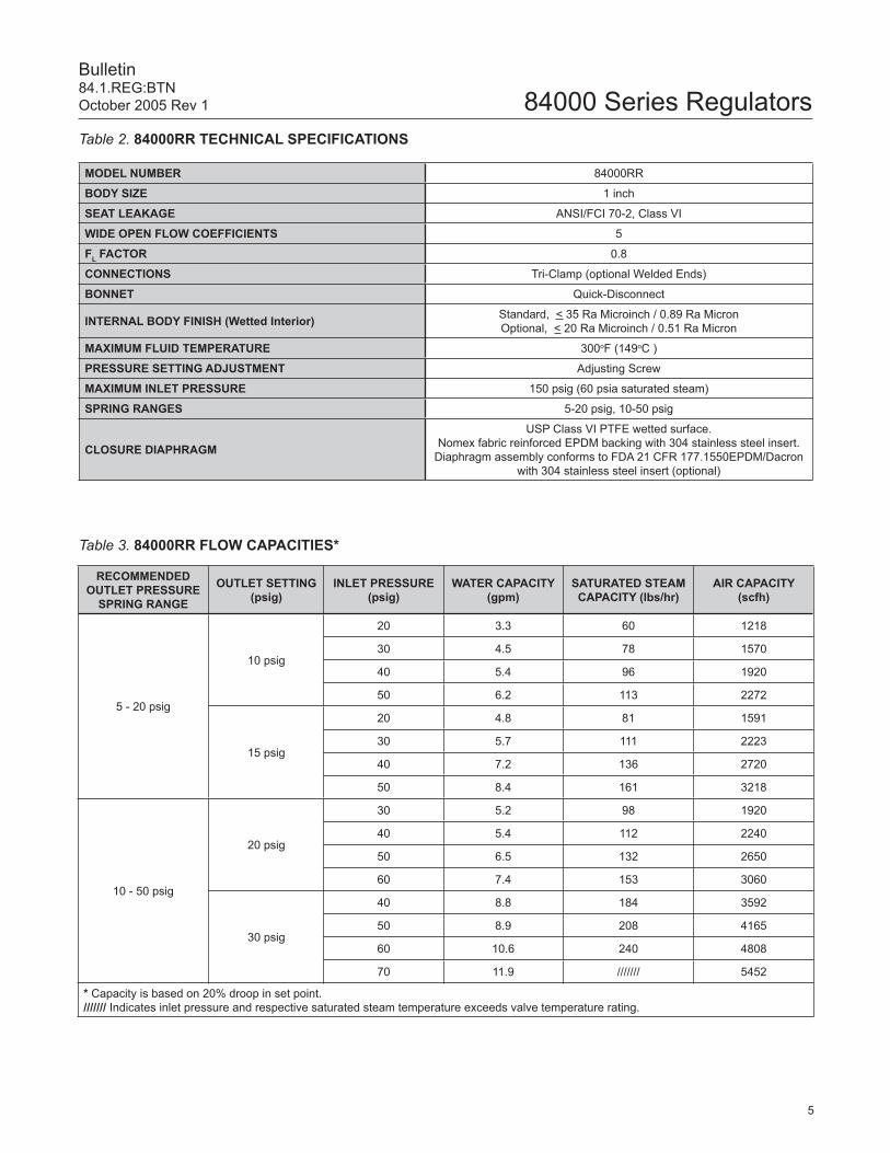
Table 2. 84000RR TECHNICAL SPECIFICATIONS
MODEL NUMBER 84000RR
BODY SIZE 1 inch
SEAT LEAKAGE ANSI/FCI 70-2, Class VI
WIDE OPEN FLOW COEFFICIENTS 5
FL FACTOR 0.8
CONNECTIONS Tri-Clamp (optional Welded Ends)
BONNET Quick-Disconnect
INTERNAL BODY FINISH (Wetted Interior) Standard, < 35 Ra Microinch / 0.89 Ra MicronOptional, < 20 Ra Microinch / 0.51 Ra Micron
MAXIMUM FLUID TEMPERATURE 300oF (149oC )
PRESSURE SETTING ADJUSTMENT Adjusting Screw
MAXIMUM INLET PRESSURE 150 psig (60 psia saturated steam)
SPRING RANGES 5-20 psig, 10-50 psig
CLOSURE DIAPHRAGM
USP Class VI PTFE wetted surface.Nomex fabric reinforced EPDM backing with 304 stainless steel insert.
Diaphragm assembly conforms to FDA 21 CFR 177.1550EPDM/Dacron with 304 stainless steel insert (optional)
Table 3. 84000RR FLOW CAPACITIES*
RECOMMENDED OUTLET PRESSURE
SPRING RANGE
OUTLET SETTING (psig)
INLET PRESSURE (psig)
WATER CAPACITY (gpm)
SATURATED STEAM CAPACITY (lbs/hr)
AIR CAPACITY (scfh)
5 - 20 psig
10 psig
20 3.3 60 1218
30 4.5 78 1570
40 5.4 96 1920
50 6.2 113 2272
15 psig
20 4.8 81 1591
30 5.7 111 2223
40 7.2 136 2720
50 8.4 161 3218
10 - 50 psig
20 psig
30 5.2 98 1920
40 5.4 112 2240
50 6.5 132 2650
60 7.4 153 3060
30 psig
40 8.8 184 3592
50 8.9 208 4165
60 10.6 240 4808
70 11.9 /////// 5452
* Capacity is based on 20% droop in set point./////// Indicates inlet pressure and respective saturated steam temperature exceeds valve temperature rating.

6
Bulletin84.1.REG:BTN
October 2005 Rev 184000 Series Regulators
7
84000 Series RegulatorsBulletin84.1.REG:BTNOctober 2005 Rev 1
84000BR Series Back Pressure Regulating and Relief Valves
These unique regulating valves are designed especially for the biotechnology industry. The 84000BR is suitable for back pressure control and relief of fluids and ultraclean steam or air. It’s light weight is ideal for thin-wall tubing.
Table 4. 84000BR MATERIALS OF CONSTRUCTION
KEY NO. DESCRIPTION MATERIAL
1 Valve Body S31600 stainless steel
2 Bonnet ASTM A276 S30400 Condition A stainless steel
3 Adjusting Screw ASTM A479 S21800 stainless steel, annealed
4 Spring Button S30300 stainless steel
5 Compressor S30300 or S30400 stainless steel
6 Range Spring S30200 or S30400 stainless steel
7 Retaining Ring S30200 stainless steel
8 Diaphragm, Closure MemberUSP Class VI PTFE wetted surface.
Nomex fabric reinforced EPDM backing with 304 stainless steel insert.Diaphragm assembly conforms to FDA 21 CFR 177.1550
10 O-ring, Stem 1Viton®-A
11 Coupling, V-Retainer S30100 stainless steel
12 Cover 18-8 stainless steel
13 O-Ring Fluoroelastomer
14 Drive Screw 18-8 stainless steel
15 Serial Plate S30400 stainless steel
16 Roll Pin 18-8 stainless steel
17 Tell Tale Port S31600 stainless steel1Viton® is a registered trademark of DuPont Performance Elastomers
Figure 5. 1 inch Body Assembly Figure 6. 1-1/2 and 2 inch Body Assembly
6
Bulletin84.1.REG:BTN
October 2005 Rev 184000 Series Regulators
7
84000 Series RegulatorsBulletin84.1.REG:BTNOctober 2005 Rev 1
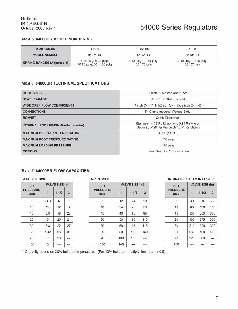
Table 6. 84000BR TECHNICAL SPECIFICATIONS
Table 5. 84000BR MODEL NUMBERING
Table 7. 84000BR FLOW CAPACITIES*
BODY SIZES 1 inch, 1-1/2 inch and 2 inch
SEAT LEAKAGE ANSI/FCI 70-2, Class VI
WIDE OPEN FLOW COEFFICIENTS 1 inch Cv = 7, 1-1/2 inch Cv = 35, 2 inch Cv = 43
CONNECTIONS Tri-Clamp (optional Welded Ends)
BONNET Quick-Disconnect
INTERNAL BODY FINISH (Wetted Interior) Standard, < 35 Ra Microinch / 0.89 Ra MicronOptional, < 20 Ra Microinch / 0.51 Ra Micron
MAXIMUM OPERATING TEMPERATURE 300oF (149oC )
MAXIMUM BODY PRESSURE RATING 150 psig
MAXIMUM LOADING PRESSURE 100 psig
OPTIONS "Zero Dead Leg" Construction
BODY SIZES 1 inch 1-1/2 inch 2 inch
MODEL NUMBER 84071BR 84351BR 84431BR
SPRING RANGES (Adjustable) 2-15 psig, 5-20 psig, 10-50 psig, 20 - 100 psig
2-10 psig, 10-40 psig, 25 - 70 psig
2-10 psig, 10-40 psig, 25 - 70 psig
WATER IN GPM AIR IN SCFH SATURATED STEAM IN LBS/HR
SETPRESSURE
psig
VALVE SIZE (in) SETPRESSURE
psig
VALVE SIZE (in) SETPRESSURE
psig
VALVE SIZE (in)
1 1-1/2 2 1 1-1/2 2 1 1-1/2 2
5 14.3 6 7 5 12 24 29 5 30 60 72
10 29 12 14 10 24 48 58 10 65 130 158
15 5.8 18 22 15 40 80 98 15 130 250 300
20 6 20 24 20 50 90 110 20 160 275 330
30 5.8 22 27 30 60 95 115 30 210 320 390
50 4.42 25 30 50 80 125 150 50 260 400 480
70 6.1 28 --- 70 100 155 --- 70 320 500 ---
100 6 --- --- 100 140 --- --- 100 --- --- ---
* Capacity based on 20% build-up in pressure. (For 10% build-up, multiply flow rate by 0.5)

8
Bulletin84.1.REG:BTN
October 2005 Rev 184000 Series Regulators
9
84000 Series RegulatorsBulletin84.1.REG:BTNOctober 2005 Rev 1
84000ABR Air-Loaded Back Pressure Regulator
The most accurate back pressure sanitary regulator in the industry. Recommended for use with centrifuges for media separation at varying densities. Remote set point adjustment is accomplished with the Fisher model 67CFR airset.
Table 8. 84000ABR MATERIALS OF CONSTRUCTION
KEY NO. DESCRIPTION MATERIAL
1 Valve Body S31603 stainless steel
2 Bonnet S30400 stainless steel
3 Diaphragm, Flat Nylon reinforced Neoprene
5 Compressor S30300 or S30400 stainless steel
7 Retaining Ring S30200 stainless steel
8 Diaphragm, Closure MemberUSP Class VI PTFE wetted surface.
Nomex fabric reinforced EPDM backing with 304 stainless steel insert.Diaphragm assembly conforms to FDA 21 CFR 177.1550
11 Coupling, V-Retainer S30100 stainless steel
12 Cover S30400 stainless steel
13 O-Ring Fluoroelastomer
14 Drive Screw 18-8 stainless steel
15 Serial Plate S30400 stainless steel
16 Socket Head Cap Screw 18-8 stainless steel
FLOW
Figure 7. 84000ABR Parts Figure 8. 84000ABR Preferred Self-draining Orientation
ï

8
Bulletin84.1.REG:BTN
October 2005 Rev 184000 Series Regulators
9
84000 Series RegulatorsBulletin84.1.REG:BTNOctober 2005 Rev 1
Table 10. 84000ABR TYPICAL WATER CAPACITIES (gpm)
Table 9. 84000ABR TECHNICAL SPECIFICATIONS
MODEL NUMBER 84000ABR
BODY SIZES 1 inch, 1-1/2 inch and 2 inch
SHUTOFF CLASS ANSI/FCI 70-2, Class VI
WIDE OPEN FLOW COEFFICIENTS 1 inch Cv = 8, 1-1/2 inch Cv = 35, 2 inch Cv = 43
FL FACTOR 0.8
CONNECTIONS Tri-Clamp (optional Welded Ends)
BONNET Quick-Disconnect
INTERNAL BODY FINISH (Wetted Interior) Standard, < 35 Ra Microinch / 0.89 Ra MicronOptional, < 20 Ra Microinch / 0.51 Ra Micron
MAXIMUM OPERATING TEMPERATURE 300oF ( 149oC )
MAXIMUM BODY PRESSURE RATING 150 psig
MAXIMUM LOADING PRESSURE 100 psig
PRESSURE SETTING ADJUSTMENT Airset, Panel loader, I/P, etc . . .
OPTIONS "Zero Dead Leg" Construction
BODYSIZE(in)
PRESSURESETTING
(psig)
PRESSURE BUILD-UP SETTING (psig)
2 4 6 8 10 15 20
1.0
5 2.6 9.0 13.3 18.1 27.8 35.7 40.0
10 2.4 9.35 15.2 21.2 26.4 40.0 43.8
20 0.5 2.0 5.1 10.6 15.8 30.7 43.0
30 0.5 1.2 3.0 6.2 8.2 20.2 30.4
1.5
5 13.2 45.0 66.3 104.6 135.5 156.5 175.0
10 6.9 44.9 70.0 106.1 134.2 175.0 191.7
20 4.7 9.8 20.4 52.9 76.7 153.8 208.7
30 4.5 5.8 9.0 30.8 44.3 100.6 155.6
2.0
5 16.4 55.2 81.6 128.4 166.5 192.3 215.0
10 8.6 55.0 86.0 130.3 164.6 215.0 235.5
20 5.6 12.3 24.9 65.1 94.2 188.7 256.2
30 5.1 6.9 10.8 38.2 54.4 123.4 191.6

10
Bulletin84.1.REG:BTN
October 2005 Rev 184000 Series Regulators
11
84000 Series RegulatorsBulletin84.1.REG:BTNOctober 2005 Rev 1
Table 11. 84000BR SERIES DIMENSION & WEIGHT (Figure 9)
VALVE SIZE
DIMENSIONSWEIGHTS
C D E F
in mm in mm in mm in mm lbs kg
1" 6.32 160.52 1.38 35.05 2.50 63.50 0.870 22.09 5 2.26
1-1/2" 7.86 199.64 2.00 50.80 3.25 82.55 1.356 34.44 13 5.89
2" 8.11 205.99 2.00 50.80 3.50 88.90 1.875 47.79 14 6.35
Figure 9. Dimensions
Figure 10. 84000BR SANITARY PRESSURE REGULATING AND RELIEF VALVE INSTALLATION(Cross-section)

10
Bulletin84.1.REG:BTN
October 2005 Rev 184000 Series Regulators
11
84000 Series RegulatorsBulletin84.1.REG:BTNOctober 2005 Rev 1
Figure 12. 84000BR THRU-PROCESS (ZERO DEAD LEG) CONNECTIONS
Figure 11. Dimensions "Zero Dead Leg"
Table 12. 84000BR “ZERO DEAD LEG” SERIES DIMENSION & WEIGHT (Figure 11)
VALVE SIZE
DIMENSIONSWEIGHTS
A B C D E
in mm in mm in mm in mm in mm lbs kg
1" 0.870 22.09 2.50 63.50 5.00 127.00 1.38 35.05 6.40 162.56 7 3.17
1-1/2" 1.356 34.99 3.25 82.55 6.50 165.10 2.00 50.80 7.90 200.66 15 6.80
2" 1.875 47.49 3.50 88.90 7.00 177.80 2.00 50.80 8.10 205.74 16 7.25
12
Bulletin84.1.REG:BTN
October 2005 Rev 184000 Series Regulators
Fisher and Baumann are marks owned by Fisher Controls International LLC, a member of the Emerson Process Management business division of Emerson Electric Co. The Emerson logo is a trademark and service mark of Emerson Electric Co. All other marks are the property of their respective owners. This product may be covered under one or more patents or under pending patent applications.
The contents of this publication are presented for informational purposes only, and while every effort has been made to ensure their accuracy, they are not to be construed as warranties or guarantees, express or implied, regarding the products or services described herein or their use or applicability. We reserve the right to modify or improve the designs or specifications of such products at any time without notice.
Neither Emerson, Emerson Process Management, Fisher, nor any of their affiliated entities assumes responsibility for the selection, use and maintenance of any product. Responsibility for the selection, use and maintenance of any product remains with the purchaser and end-user.
Emerson Process Management
Fisher Controls International LLCBaumann Valve Division130 International DrivePortsmouth, NH 03801T: 1 (603) 766-8500F: 1 (603) 766-8590www.baumann.com
© Fisher Controls International LLC 2005; All Rights Reserved. Printed in USA
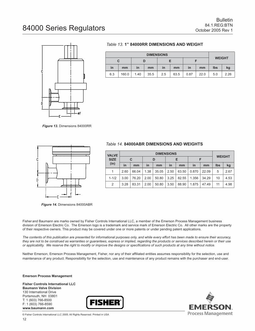
Table 14. 84000ABR DIMENSIONS AND WEIGHTS
VALVE SIZE(in)
DIMENSIONSWEIGHT
C D E Fin mm in mm in mm in mm lbs kg
1 2.60 66.04 1.38 35.05 2.50 63.50 0.870 22.09 5 2.67
1-1/2 3.00 76.20 2.00 50.80 3.25 82.55 1.356 34.29 10 4.53
2 3.28 83.31 2.00 50.80 3.50 88.90 1.875 47.49 11 4.98
Table 13. 1” 84000RR DIMENSIONS AND WEIGHT
DIMENSIONS WEIGHT
C D E F
in mm in mm in mm in mm lbs kg
6.3 160.0 1.40 35.5 2.5 63.5 0.87 22.0 5.0 2.26
Figure 13. Dimensions 84000RR
Figure 14. Dimensions 84000ABR


![Igorlied [de Baumann]](https://static.fdocuments.net/doc/165x107/563db8b5550346aa9a963434/igorlied-de-baumann.jpg)