Battlin’ Pete II 10 th International Submarine Race David Taylor Model Basin Washington DC,...
12
Battlin’ Pete II 10 th International Submarine Race David Taylor Model Basin Washington DC, Maryland June 25, 2007
-
Upload
melissa-ferguson -
Category
Documents
-
view
222 -
download
1
Transcript of Battlin’ Pete II 10 th International Submarine Race David Taylor Model Basin Washington DC,...

Battlin’ Pete II
10th International Submarine RaceDavid Taylor Model Basin Washington DC, Maryland
June 25, 2007

Design Team
David Hume Peter Moser- Design & Propulsion - Safety
Cale Jurin Cale Jurin - Pedals & Cables - Elevator & Controls
David Hume Peter Moser - Air Systems - Rudder & Controls

Goals
• To increase the speed obtained by Battlin’ Pete I while using the same hull form but different propulsion.
• Simplistic and robust construction. • Safe and easy control and operation. • Spend less than $100 on
construction and supplies.

Philosophy
• Mimic nature; i.e. the swimming motion of a penguin.
• Flapping foil propulsion studies led to identify strouhal number range .2~.4 for animals.
St = f a / Vwith an projected speed of 3 knots:
.3 = f (3’stroke)/ (5 ft/sec) f = .5Hz = 30 RPM target frequency
• Use leg press motion for increase in power input. (previous design had single fin with no counterforce)
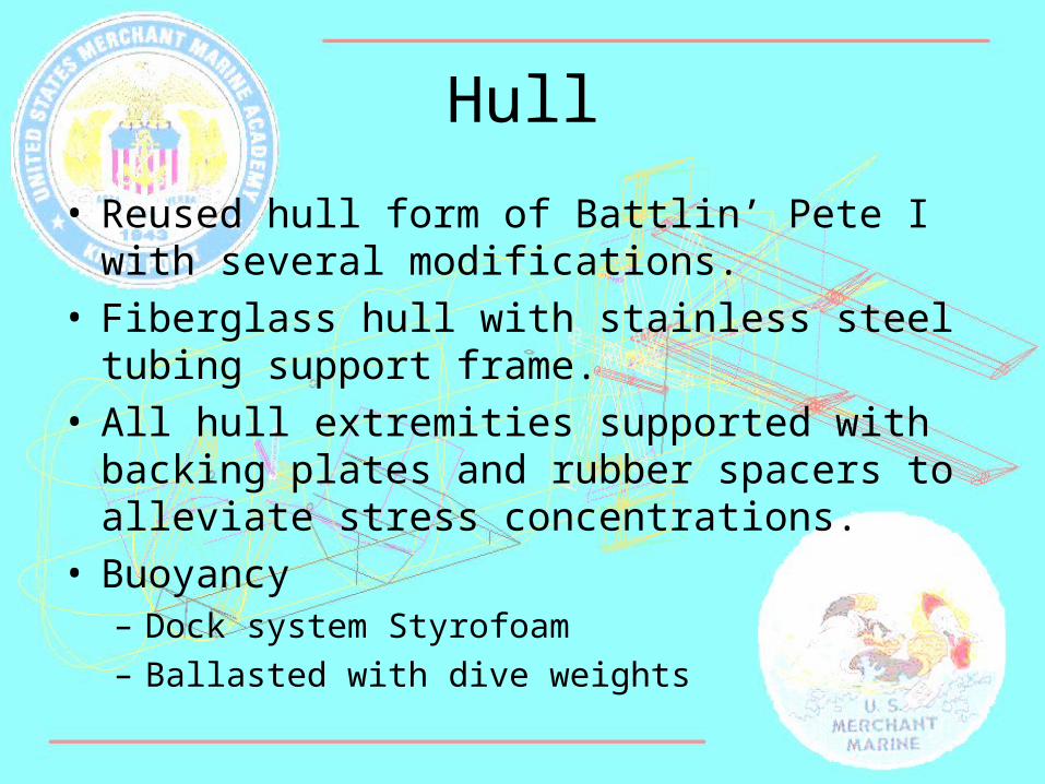
Hull
• Reused hull form of Battlin’ Pete I with several modifications.
• Fiberglass hull with stainless steel tubing support frame.
• All hull extremities supported with backing plates and rubber spacers to alleviate stress concentrations.
• Buoyancy – Dock system Styrofoam – Ballasted with dive weights

Propulsion
• Hobie Mirage Drive used for foil due to flexibility (prevent stalling and separation effects) and proven effectiveness
• Controlled heaving and pitching motion
• Adjustable foot pedals to accommodate different drivers
• Sprockets and cam transmission.

ControlElevators
– Dagger boards used from small sailing craft. – Interconnected control of each fin by single
lever. – Located on forward third of hull length for
increased maneuverability.
Rudder – Plywood formed to steam lined shape of
rudders.– Utilizes a closed loop pulley system (crew shell)– Located on top of hull
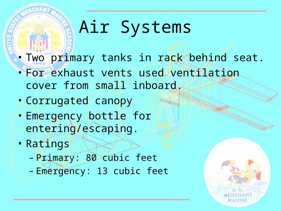
Air Systems
• Two primary tanks in rack behind seat.• For exhaust vents used ventilation
cover from small inboard.• Corrugated canopy• Emergency bottle for entering/escaping. • Ratings
– Primary: 80 cubic feet– Emergency: 13 cubic feet

Safety
• Reserve buoyancy ballasted down with dive weights
• Emergency Buoy with high visibility line• Running Lights • Transparent easy opening cover• Non-skid pedals • Quick release harness • High visibility paint on all fins, stabilizers,
and elevators

Timeline
• Week 1-4 Design– Incorporate new design into original hull form – Removal of internals and dry planning/
measuring
• Week 5-17 Re-Construction/ Revisions– Collection/purchasing of materials – Measuring, cutting, welding, machining,
installing, painting, waxing.
• Week 17-19 Testing – In pool to fine tune buoyancy & stability– Controls and propulsion motion

Budget < $100• Majority of raw materials was used from scrap
piles around campus:– Aluminum mast from sailing team – Chair provided by Band Company Ward Room.
• Welding supplies and tools provided by Joe Kass (USMMA welding instructor)
• Hobie Mirage drive donated by Hobie Company• Items bought from Granger:
– Steel cable– Transparent PVC sheet– Velcro– Assorted nuts and bolts

Closing
• Learning Experience – Welding Techniques (aluminum, stainless steel,
mild steel) – Fiberglass Construction
• Modified original design continuously throughout construction
• Future modifications should include:– Hull form changes, reduce cross sectional area by
putting driver in prone position (drag reduction)– Additional drive either on top or directly behind in
tandem