
BATTERY TYPE
12
Transcript of BATTERY TYPE

1
BATTERY TYPE APPLICATIONS PzS Wet (Lead Acid)
CHARGING TIME
WoWa 8-10H / Wa 10-12H
TECHNICAL FEATURES Power Supply:
Single Phase 220-230-240-255 Vac / 50-60Hz
Three Phase 380-400-420-440 V / 50-60 Hz
Tropicalized stray-flux transformer impregnated with non-toxic resins and kiln dried
Microchip Microcontroller PIC16TM/PIC18TM Automatic equalization charge to prevent sulphation
Maintenance charge to prevent battery self-discharge Automatic restart after overheat anomaly or power supply interruption
Cabinet protection IP21 WA or WoWa Charging curve
Current Value reading with SHUNT 100 charging cycles log (Duration of the charge, AH delivered)
Power transformer with ventilation Channels (20% cooler) Visualization of estimated charging cycle’s length
ABS front and back panels to increase efficiency by 5-7% Low output noise while charging
SAFETY FEATURES Short circuit and reverse polarity protection with fuse Overheat protection with thermal probes and control card Double safety timer Error codes visualization on display Safe battery disconnection during charge Battery health check before charge begins Buzzer noise in case of error or malfunction Anomalies management trough microcontroller Protection against overcurrent and overvoltage Protection over every charging phase of the cycle
GENERAL FEATURES Backlit 16x2 characters alphanumeric display High luminescence LED on the front panel Charging parameters visualized on display Adjustable final charging stage (from 1 to 10H), standard is 4h
ACCESSORIES Cable Hook Easy Wire System (only Box “S”) PRO Control Card (Box “S-C” Modular accessories related to PRO Control Card Kit Update Software Cable’s plugs Battery temperature probe connected to the charger Cabinet Stand
Bro
chur
e su
bje
ct t
o ch
ange
s w
itho
ut
no
tice
EVO Series

2
CHARGER SIZES AH RECHARGE CHART
Nominal Vdc
V Vac
Output Current
A
Output Current
A
AH (C5)
WoWa Wa
8H 10H 12H
From To
20A / 120 160
12V 1x 230 Vac 20 40 30A / 180 230
40A / 230 290
24V 1x 230 Vac 20 160 50A / 300 380
3x 400 Vac 60 180 60A 260 375 450
70A 300 385 470
36V 1x 230 Vac 30 160 80A 350 420 600
3x 400 Vac 60 180 100A 435 520 750
120A 525 600 900
48V 1x 230 Vac 20 120 140A 610 720 1050
3x 400 Vac 40 200 160A 700 820 1200 180A 785 900 1350
72V 1x 230 Vac 60 120 200A 870 1040 1450
3x 400 Vac 60 120
80V 1x 230 Vac 60 100
3x 400 Vac 60 180
WORKING CONDITION
Operating Temperature From -20°C to +45°C Maximum Humidity 90% without condensation
Storage Temperature From 0°C to +60°C Environment Not Alkaline
CHARGING CURVES BOX GUIDE
DIMENSIONS
Box H L D
“P” 270 360 270
“E” 860 370 510
COLORS
Front Panel White RAL 9010 Gray RAL 7004
Box Orange RAL 2002 Black RAL 9011 Green RAL 6017
Bro
chur
e su
bje
ct t
o ch
ange
s w
itho
ut
no
tice
Values referred to a 80% discharged PzS Wet (Lead Acid)
traction battery.
To request other V/A, please contact us through our website
www.tcechargers.com
In case of environments with different values from the above, please contact us to evaluate further options
The box is based on the size of the power transformer to
optimize the charger’s operation.
“E”
“P”
3
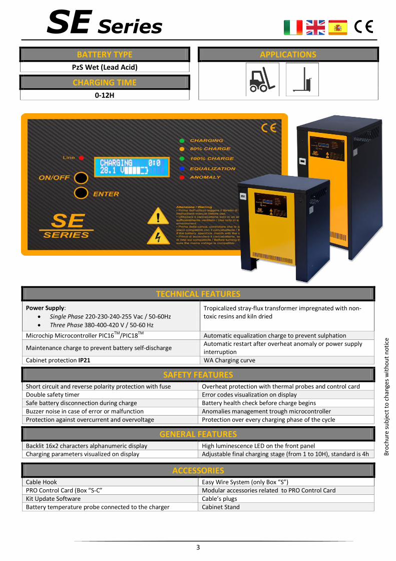
BATTERY TYPE APPLICATIONS
PzS Wet (Lead Acid)
CHARGING TIME
0-12H
TECHNICAL FEATURES Power Supply:
Single Phase 220-230-240-255 Vac / 50-60Hz
Three Phase 380-400-420 V / 50-60 Hz
Tropicalized stray-flux transformer impregnated with non-toxic resins and kiln dried
Microchip Microcontroller PIC16TM/PIC18TM Automatic equalization charge to prevent sulphation
Maintenance charge to prevent battery self-discharge Automatic restart after overheat anomaly or power supply interruption
Cabinet protection IP21 WA Charging curve
SAFETY FEATURES Short circuit and reverse polarity protection with fuse Overheat protection with thermal probes and control card Double safety timer Error codes visualization on display Safe battery disconnection during charge Battery health check before charge begins Buzzer noise in case of error or malfunction Anomalies management trough microcontroller Protection against overcurrent and overvoltage Protection over every charging phase of the cycle
GENERAL FEATURES Backlit 16x2 characters alphanumeric display High luminescence LED on the front panel Charging parameters visualized on display Adjustable final charging stage (from 1 to 10H), standard is 4h
ACCESSORIES Cable Hook Easy Wire System (only Box “S”) PRO Control Card (Box “S-C” Modular accessories related to PRO Control Card Kit Update Software Cable’s plugs Battery temperature probe connected to the charger Cabinet Stand
Bro
chur
e su
bje
ct t
o ch
ange
s w
itho
ut
no
tice
SE Series

4
CHARGER SIZES AH RECHARGE CHART
Nominal Vdc
V Vac
Output Current
A
Output Current
A
AH (C5)
10H 12H
From To
20A 100 130
12V 1x 230 Vac 20 40 30A 140 190
40A 190 240
24V 1x 230 Vac 20 160 50A 250 315 3x 400 Vac 60 180 60A 300 370
70A 320 390
36V 1x 230 Vac 30 160 80A 350 500 3x 400 Vac 60 180 100A 430 620
120A 500 750
48V 1x 230 Vac 20 120 140A 600 870 3x 400 Vac 40 200 160A 680 1000
180A 760 1125
72V 1x 230 Vac 60 120 200A 1100 1250 3x 400 Vac 60 120
80V 1x 230 Vac 60 100
3x 400 Vac 60 180
To request other V/A, please contact us through our website
www.tcechargers.com
WA CHARGING CURVE BOX GUIDE
“S” “C” “M”
WORKING CONDITION DIMENSIONS
Box H L D Operating Temperature From -20°C to 35°C “M” 260 350 260 Storage Temperature From 0°C to 60°C “C” 600 500 380 Maximum Humidity 90% without condensation “S” 860 370 510
Environment Not Alkaline
COLORS
Front Panel White RAL 9010 Yellow RAL 1028
Box Orange RAL 2002 Black RAL 9011 Green RAL 6017
The box is based on the size of the power transformer to optimize the charger’s operation.
Bro
chur
e su
bje
ct t
o ch
ange
s w
itho
ut
no
tice
Values referred to a 80% discharged PzS Wet (Lead Acid)
traction battery.
In case of environments with different values from the
above, please contact us to evaluate further options

5
SERIES CABINETS APPLICATIONS
SE Series: “C-S” EVO Series: “E”
Fleet & Battery Management
System Rentals DATA Analysis
FEATURES
TFT Graphic display with 2.8 inches Color display for fast and simple visualization of the charging cycles and charger’s functions
Visualization of basic information on the main visual:
Temperature inside the charger
Date and time
Humidity inside the charger
Company logo
Charger’s size (V, A, phase)
RGB Led under touchbuttons with different colors and flashing patterns assigned to the many functions and charging phases
Integrated touchbuttons (no physical buttons on the card) Protection against dust, water or other object to enter the card housing slot
Storage of 1000 charging cycles with possibility to visualize directly on display or download with Data BOX accessory
Error visualization with detailed description of the error. Date and time are also shown.
Language selection: IT, EN, DE, ES Possibility to increase the ABS Time (from 80% to 100% charge) from 1h to 5h, standard set is 4h
Buzzer to notify the user in case of errors/anomalis Possibility to control the charge by using the modules and accessory
ACCESSORIES AND MODULAR FEATURES
Data BOX accessory to download the data log from the PRO Card to a PC.
Wi-Fi Module accessory adds the possibility to download the data with Wi-Fi connection to any device with a Wi-Fi receiver (phone, tablet, PC)
Automatic Watering System to automatically water the battery following the parameters set on the display
Access point to download the data log on a local server or a remote server. Can be used with Wi-Fi Module to avoid Ethernet cables.
CAN/BUS Battery Module to give an ID to the battery and monitor battery temperature and water level. It can stop the charge in case of overheat of the battery (with automatic re-start once cooled off) and don’t let the charge start if the water level is too low. Possibility to analyze the downloaded data on PC with the utility tool or with the TCE Cloud™ found on our website with any PC. Through the TCE Cloud™ is possible to monitor many batteries and chargers sorted by customers.
Bro
chur
e su
bje
ct t
o ch
ange
s w
itho
ut
no
tice
PRO Control Card
IMPORTANT: For EVO Series is only required to change the
control card, for SE Series the PRO Control Card MUST be
installed in our factory.

6
MENU VISUALIZATIONS
Main Display
The main display is shown when the charger is in idle. After 5 minutes of inactivity, the screen will turn off.
In case of modules attached, additional icons will appear on this visual
Data Log Menu
The Data Log menu offers the possibility to visualize the stored charging cycles.
The result of the selected charge is shown in different colors together with other important information
Settings Menus
Through the settings menus is possible to change the visualization and storage of the parameters read.
It is also possible to change the language of the charger’s software (IT-EN-DE-ES)
Password and Special Menus
By doing a combination with the touchbuttons, it’s possible to access to the Password visualization.
Different password unlocks different level of access to change important settings of the charger
CHARGING VISUALIZATIONS
During the charging cycle, on the display is shown a battery with different colors based on the battery charge status.
The touchbuttons also change colors based on the charge status or the function the charger is performing .
Once the charge is complete, the additional integrated functions (Equalization and Maintenance) will automatically start
Bro
chur
e su
bje
ct t
o ch
ange
s w
itho
ut
no
tice

7
REQUIREMENTS APPLICATIONS PRO Control Card
Fleet & Battery Management
System
Rentals
DATA Analysis
OPTIONALS
Water Level Sensor
Temperature Probe
DESCRIPTION AND SCHEMATIC
Schematic
Description
The CAN-BUS Bms Module allows the charger to gather more information regarding the battery connected to it and to give further control over the charging cycle. If the optionals Water Level Sensor and Temperature Probe are installed, the PRO Control card can stop the charging cycle if the temperature rises above 60°C and automatically re-start it if it lowers below 45°C. It can also prevent the charge from starting if the water level measured from the Water Level Sensor is too low. By Giving an ID to the Battery and Charger, is possible to keep an accurate track of the battery life. Combining with each other, the IDs can give full control over big fleets and rentals units. This helps to keep the warranty of the controlled units under check and have accurate data of the customer usage. The tools provided by TCE Srl to do it are the PC Utility Tool Software, a simple executable program that doesn’t require any installation, and the TCE Cloud™ service found on our website.
FEATURES
Possibility to give a customized ID to the battery Through the ID, is possible to monitor the battery life and have a full report using the Utility Tool on a PC
Battery IDs and Charger IDs can combine with each other to give a detailed history of both the battery and the charger
Possibility to control many big fleets sorted by customer using the TCE Cloud™ directly on our website.
In case of optionals installed, the charge can be further controlled to prevent any damage to the battery
Bro
chur
e su
bje
ct t
o ch
ange
s w
itho
ut
no
tice
CAN-BUS BMS
IMPORTANT: The Battery Module requires a 24V power
supply (12 Cells)
IDxxx
IDyyy
IDzzz
ID123
Battery Charger
with BMS Module installed
Charger PC Utility Tool
OPTIONAL TCE Cloud™ Data Analysis Batteris with
BMS Module installed

8
REQUIREMENTS
APPLICATIONS PRO Control Card
Fleet & Battery Management
System
Rentals
DATA Analysis
Wi-Fi RANGE
150 Mt
COMPATIBLE OS
DESCRPITION AND CONNECTION SCHEMATIC
Schematic
Description
When a device is connected to the Wi-Fi Charger Module, through a web interface it will be possible to visualize in real time what the charger is doing (charging cycle and functions), download the stored data inside the PRO Control card and analyze it.
The Module can be connected to a local server to automatically and periodically upload all the stored data. By using the TCE Cloud™ service directly on our website, analyze all the stored data from all the chargers connected to the local server is simple and intuitive.
In case of Access Point (or 3G/4G Dongle), the upload of the files can be to an external server. In this case it will be possible to remotely view the data of the Chargers on a webinterface.
The connection between the Local Server and the Access Point can be wireless or via a normal Ethernet Cable.
The USB Port, installed on the Module, allows the automatic download of the data on a storage device (Ex. USB PenDrive) and update the software of the system installed (Wi-Fi Module, PRO Control card and Can/Bus module if installed).
FEATURES Create an hotspot of the charger with unique name to wireless download the stored data inside the PRO Control card
Can connect to any device with Wi-Fi Receiver (phone, tablet, PC, etc.)
Ethernet port integrated to physically connect the charger to a PC, router or modem
USB Port to automatically download data directly on a Storage unit (ex. USB Pendrive) or to update the Firmware/Software of the system
Can connect to a local or remote server to automatically and periodically upload the stored data. Through our TCE Cloud™ is possible to thoroughly analyze the data uploaded
Wi-Fi Charger Module
Wi-Fi Module with
Ethernet and USB Port
Wi-Fi Module with
Ethernet and USB Port
Devices with Wi-Fi Receiver
(phone, tablet, PC, etc etc)
Devices with Wi-Fi Receiver
(phone, tablet, PC, etc etc)
Local Server or Access point
OPTIONAL: 3G/4G Dongle for
internet connection in isolated
areas

9
CABLE MANAGEMENT SYSTEMS
Easy Wire System Cable Hook
The Easy Wire System is an automatic winding system of the charging cables. It preserves the quality of the cables, preventing any damage and guaranteeing their flexibility over time. This system also preserve the integrity of the connector that, when the cables are inside the cabinet, will hang just outside the exiting hole of the cabinet. This system cannot be installed after sale. Can be installed in the “S” and “E” cabinets.
A rally simple but efficient and economical solution to prevent the damaging of the charging cables. This accessory can be integrated on the charger after sale, offers a solution to the common problem of the damaging of the charging cables. Made with galvanized metal to prevent the formation of rust, colored with Anti-UV powder paint to prevent the fade of the color in case of direct sunlight for an extended period of time
CASE STAND CONNECTORS
The case stand is a handy accessory to preserve the integrity of the cabinet. Made with galvanized metal and then treated to withstand harsh working environments and bad weather, it offers a simple solutions to prevent damage caused by accidental bumps and hits. When the charger is on the stand, is possible to move it with a stacker or a fork truck.
It is possible to attach to the charger the battery plug and power plug to make the charger ready to use once received. We only high quality connectors from the main brands (REMA, Power Anderson, Ravioli, etc. etc.) to guarantee to the customer a correct execution of the charging cycle.
AUTOMATIC WATERING SYSTEM SIDE HANDLES
A feature that can be integrated within the PRO Control Card is the Automatic Watering System. This function allows the automatic watering of the battery with a system supplied by TCE. It is possible, through the display, to change the watering settings based on the battery brand and specifics, to guarantee its optimal topping.
The handles help the user to move the charger without any problems. They are simply installed through the side slits. Simple but yet useful, this accessory is avoids damage to the charger while moving it.
Accessories
For other accessories, please visit the Accessories section in our website www.tcechargers.com/Accessories

10
What is the length of the cable? The standard length of the cables supplied with T.C.E. chargers is 2 meters for the power cable and 2,8 meters for the exciting cable (red and black).
Why the charger is not turning on? The most common reasons why the charger is not turning on are:
Power supply is missing
Charger is not connected or not properly connected to the battery.
Wrong battery voltage
Battery is already fully charged
Fuse is blown
Anomalies The most common reasons why the anomalies are shown on the display or notified through the red LEDs on the front panel are:
The maximum charging time has been exceeded
Battery has been overly charged
Charging current is too high because of the wrong network voltage
Network is missing one phase
Defective battery or completely exhausted
Lack of a network connection during the charging cycle (Blackout)
Overheating (thermal-probe intervened)
SOLUTION: repeat the standard charging cycle, if the problem persists contact a technician.
Choose the correct charger for your fork truck To choose the most suitable charger for your battery check our website www.tcechargers.com and follow the guide “Choose in 3 steps” or follow the following
advices:
Based on the battery voltage, having the Ah capacity of the battery is possible to calculate the best charger for this battery
Example: battery 48V 600Ah – the charger must be the 16% of the battery capacity so 600Ah x 16% = 96Amp, adapt with the model that is closer to
the result so the in this case the best model would be a 48V 100Amp
Based on the time available to complete the charge:
Fast charge in 8-9h with the model WoWa
Standard charge in 10-12h with the model Wa
Considering the use of the fork truck
Example: if a battery is a 680 Ah x 16% = 109 Amp, the closest model would be a 120 Amp for a frequent use (daily charge) or choose a 100Amp for an
occasional use (a couple of times a week).
What is the equalization charge? The equalization charge is a supplementary charge that improves the energy performance of the battery. Its purpose is to balance the charging level of the
battery elements.
The charge starts automatically when the pre-set parameters on the control card match the parameters recorded directly from the battery.
This phase is handled by the microprocessor that decides both the length of the small charges and the length of the pauses based on the bat tery capacity.
How does the Maintenance Charge work?
The maintenance charge is used to avoid the inevitable natural loss of the battery charge. The T.C.E. chargers keep the voltage next to 2,3 V/el (Example: 26,76
for 24V batteries), and gives the current requested by the battery. When it starts, the charger at first gives the maximum current and then it starts to decrease
with the increasing of the battery voltage until it reaches the maintenance level. The advantage is that the charger can remain connected to the battery for long
periods of time and keep the battery always fully charge without provoking any damage.
How to optimize the performances and the lifespan of your battery
Batteries only require a low maintenance to be preserved in an optimal state:
Avoid to discharge the battery over 1,7V/el (Example 20,4 for 24V batteries). Plates are submitted to an excessive mechanical stress because of the variations of the volume of the active matter, they can be seriously damaged.
Avoid to overly charge or not charge enough the battery. The over charge of the battery can cause o overheat of the elements causing the active mater to emerge from the positive plates.
Never leave the battery unused for long periods, this causes sulfation phenomenon
Periodically check the electrolyte level. Make sure that the level is a centimeter above the upper side of the grids (if left uncovered by the electrolyte the part above the level will rapidly sulfate)
FAQ

11
TCE Srl Via G. di Vittorio, 5 Web: www.tcechargers.com
35046 Saletto (PADOVA) Mail: [email protected]
ITALIA Tel: +39 0429 89290
P.IVA IT01385440282
About Us
TCE was founded in 1960 and is one of the oldest Italian producers of battery chargers for traction batteries.
Through the many years of experience, studies and researches we developed new cutting edge technologies
to guarantee the best charge for the battery and optimize its performances.
The solutions we offer:
Battery Chargers
Service Chargers
Dischargers (Battery Capacity Testers)
Battery Regeneration Products
Accessories to preserve the battery and the charger good conditions
Fleet Management System
Access point (for remote control and data download, live streaming of the charge and real time
battery status, can be implemented with only the Wi-Fi Module)
Data Analysis Solutions (TCE Cloud™)
Our Mission is to create long lasting partnership with our distributors, grow together and create a worldwide
network to distribute a product able to optimize and extend the battery life and performances over the years.


