Basics of Infrared Thermography - AVO Training Institute · • A thermal infrared camera detects...
58
1 Basics of Infrared Thermography © AVO Training Institute, Inc. 2018
Transcript of Basics of Infrared Thermography - AVO Training Institute · • A thermal infrared camera detects...
1
Basics of Infrared Thermography
© AVO Training Institute, Inc. 2018
2
Moderator
n Ron Spataro AVO Training Institute Marketing Manager
3
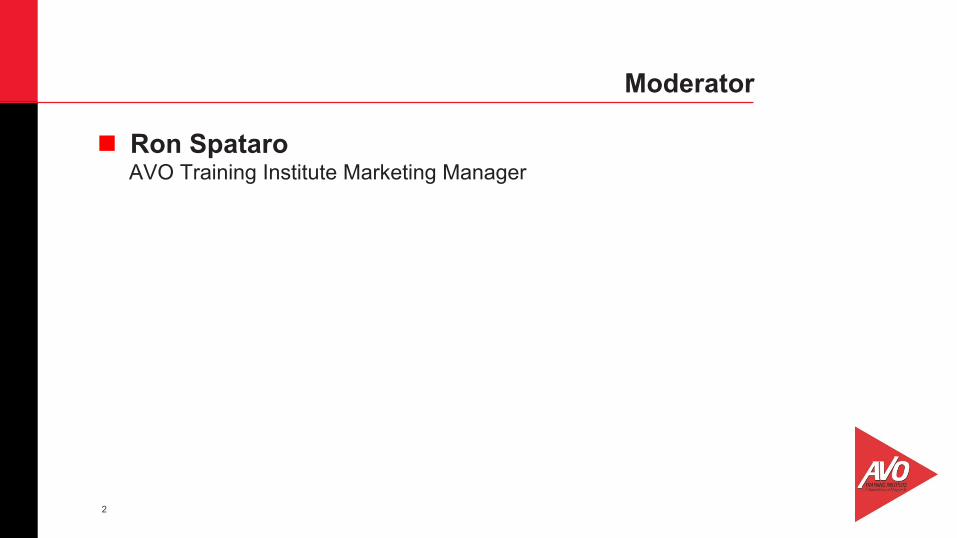
Q&A
n Send us your questions and comments during the presentation
4
Today’s Presenter
Mike Carter AVO Training Institute, Senior Instructor and Curriculum Advisor
5
Definition • Thermography is the imaging or viewing of an object or
process through sensing of infrared radiation emitted by it. • Temperature patterns on the material surface produce
corresponding radiation patterns. • Heat flow by conduction and radiation may be observed and
used to locate material discontinuities. • Infrared thermography is imaging of a temperature field
through the emitted infrared radiation.
Definition and History of Thermography
6
Definition: • The result is a picture called a thermograph.
History: • Infrared technology started in 1800 with William Herschel
and a famous experiment that revealed the existence of the infrared radiation spectrum.
• Herschel was concerned with the similarity between heat and light. He called his discovery “invisible rays.”
Definition and History of Thermography
7
History: • Herschel saw that transmission of those invisible rays is
affected by material properties. • He also noticed that the heating rays are reflected following
the same rules as visible rays. • During World War II many patents were released.
Applications included detection of soldiers, machinery, ships, icebergs and guidance of torpedoes.
Definition and History of Thermography
8
Heat:
n Energy has several forms such as kinetic which is a form that an object has by reason of its motion.
n The kind of motion may be, rotation about an axis, vibration, or any combination of motions.
n The energy principle is that energy cannot be created or destroyed, although it can be changed from one form to another.
Heat and Temperature
9
Heat:
n Forms of energy that can be converted and changed to forms of work - Mechanical - Electrical - Chemical - Nuclear - And more!
n Energy in physics is the capacity for doing work.
Heat and Temperature
10
• Heat:
n The second law of thermodynamics states that energy moves from areas of high temperature to areas of low temperature.
n Heat is simply a form of energy that is transferred by a difference of temperature.
n Temperature is the measure of hotness expressed in terms of any of several scales, such as Fahrenheit, Celsius, or Kelvin.
Heat and Temperature
11
Temperature: • Temperature is a measure of the average energy of the
molecules of a body (how much the atoms and molecules vibrate or oscillate)
• Whereas heat is a measure of the total amount of thermal energy in a body.
• The most common temperature scales are based on arbitrarily defined fixed points.
Heat and Temperature
12
Temperature:
n Fahrenheit scale sets 32˚ as the freezing point of water and 212˚ as the boiling point of water (at standard atmospheric pressure).
n The Celsius scale sets 0˚ and the boiling point at 100˚. n On the Celsius scale 0˚C = 32˚F on the Fahrenheit scale. n All materials (hot or cold) transfer heat and radiate infrared
energy. As a material is cooled, it continuously loses heat and radiation power.
Heat and Temperature
13
Temperature: • A simple definition of temperature is that it is a measure of
average vibration and translation associated with the disordered motion of atoms and molecules.
• The hotter the molecules, the faster they will vibrate. • The opposite would be true if the material gets cooler: the
molecules will vibrate slower.
Heat and Temperature
14
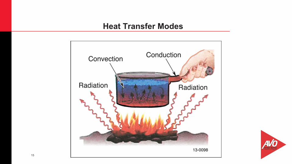
• The energy which is moving from one system to another is known as heat.
• The transfer or dispersion of heat can occur by means of three main mechanisms:
• Conduction • Convection • Radiation • Understanding the three modes of heat transfer provides the
background to understand how the surface is heated.
Heat Transfer Modes
15
Heat Transfer Modes
16
• Heat transfer starts out as transient (changing with time) and then approaches steady-state with time until the difference between the actual and the ideal becomes negligible or until thermal equilibrium is approached.
• Heat capacity is a measure of an object’s “capacity” to hold “heat.”
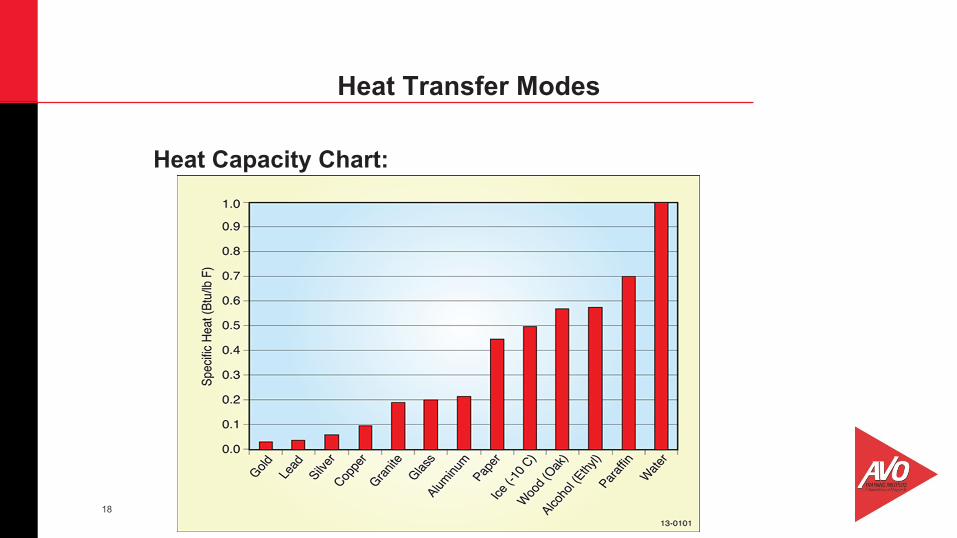
• Materials with high heat capacities, such as water, require large amounts of energy to produce a small temperature change.
• Heat capacity is an essential parameter considered in many fields of engineering from architecture to aerodynamics.
Heat Transfer Modes
17
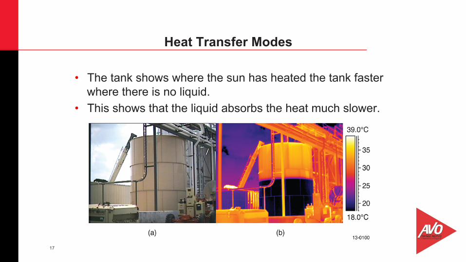
• The tank shows where the sun has heated the tank faster where there is no liquid.
• This shows that the liquid absorbs the heat much slower.
Heat Transfer Modes
18
Heat Capacity Chart:
Heat Transfer Modes
19
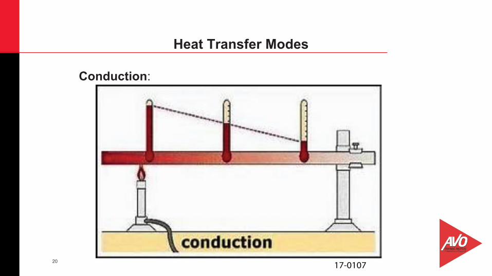
• Conduction is the movement of heat through a substance by the collision of molecules.
• At the place where the two objects touch, the faster moving molecules of the warmer object collide with the slower moving molecules of the cooler object.
• This process continues until heat energy from the warmer object spreads throughout the cooler object.
Heat Transfer Modes
20
Conduction:
Heat Transfer Modes
17-0107
21
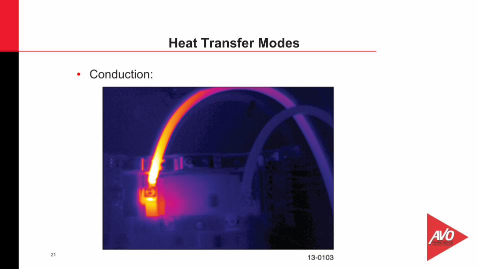
• Conduction:
Heat Transfer Modes
22
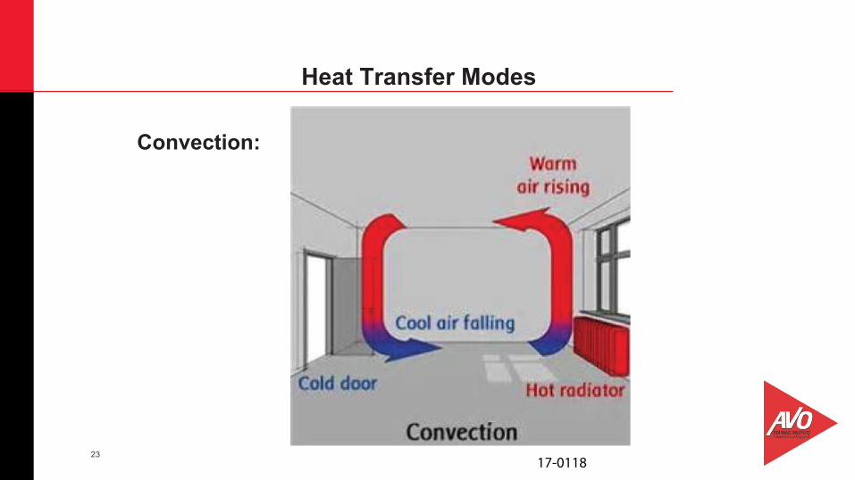
• Convection is defined as a type of heat transfer that takes place in a moving medium and is almost always associated with transfer between a solid (surface) and a moving fluid (such as air), whereby energy is transferred from higher temperature sites to lower temperature sites.
• The expression has been heard “Hot air rises and cool air falls to take its place.”
• This is a description of convection in the atmosphere. • Heat energy is transferred by the circulation of the air. • A hair dryer is a perfect example of forced convection.
Heat Transfer Modes
23
Convection:
Heat Transfer Modes
17-0118
24
• It does not take much wind to greatly reduce the temperature differentials that the thermographer relies on to find and estimate problems.
• The cooling effect of the wind increases with the wind speed, a 10 MPH wind can reduce the target ΔT being observed and measured by 1/2 and a 15 MPH wind reduces the target temperature by 2/3.
• Thermal radiation is a mode of heat flow that occurs by emission and absorption of electromagnetic radiation, propagating at the speed of light and unlike conductive and convective heat flow, capable of propagating across a vacuum.
Heat Transfer Modes
25
• Radiation is the form of heat transfer that allows infrared thermography to work because infrared energy travels from the target to the detector by radiation.
• Radiation is different from the other forms of heat transfer because electromagnetic waves do not need any material for their propagation.
• In still air the human body loses nearly 2/3 of its body heat through radiation to wall surfaces around it.
• As the temperature differences go up, radiation heat transfer rates rise exponentially.
Heat Transfer Modes
26
• The radiosity concept is the total infrared energy leaving a target.
• This is composed of radiated, reflected and transmitted components.
• The radiated component is the only one that is related to target surface temperature.
• Three things can happen to infrared radiation striking or incident on an object , it can be: absorbed, reflected or transmitted.
Radiosity Concepts
27
• The part of incident radiation that is absorbed, reflected and transmitted is described by properties of materials called: absorptivity, reflectivity and transmissivity.
• Absorption: Some of the incident radiation is absorbed by an object and is converted to heat.
• Reflection: Part of the radiation is reflected at the surface of the object.
• Transmission: Some of the radiation passes through the object, just as light passes through glass.
• The total amount of incident radiation to an object is equal to the absorbed, reflected and transmitted radiation.
Radiosity Concepts
28
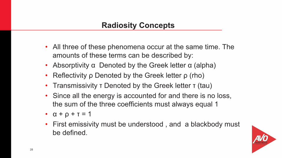
• All three of these phenomena occur at the same time. The amounts of these terms can be described by:
• Absorptivity α Denoted by the Greek letter α (alpha) • Reflectivity ρ Denoted by the Greek letter ρ (rho) • Transmissivity τ Denoted by the Greek letter τ (tau) • Since all the energy is accounted for and there is no loss,
the sum of the three coefficients must always equal 1 • α + ρ + τ = 1 • First emissivity must be understood , and a blackbody must
be defined.
Radiosity Concepts
29
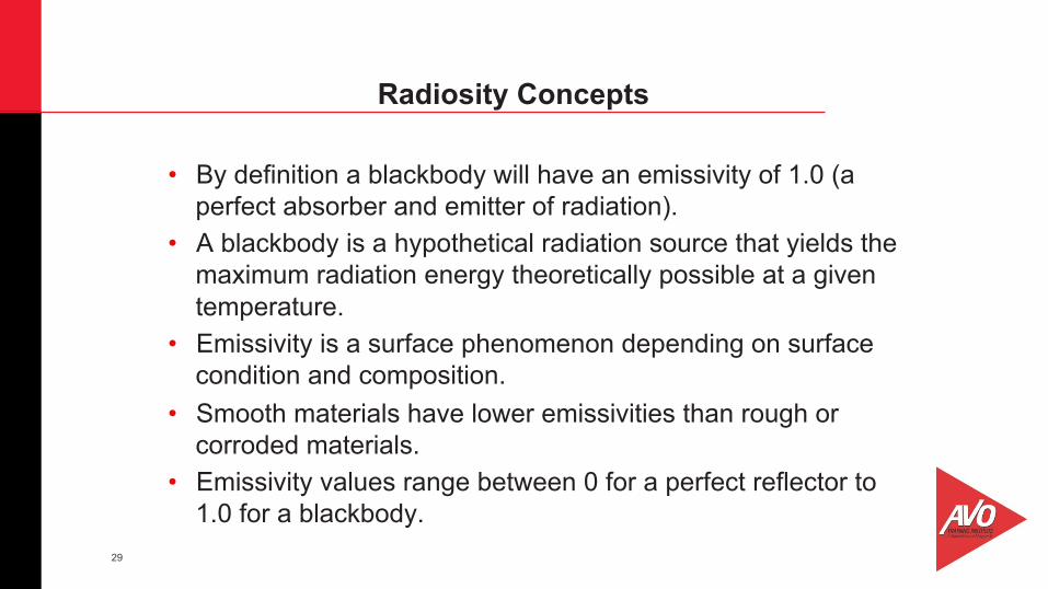
• By definition a blackbody will have an emissivity of 1.0 (a perfect absorber and emitter of radiation).
• A blackbody is a hypothetical radiation source that yields the maximum radiation energy theoretically possible at a given temperature.
• Emissivity is a surface phenomenon depending on surface condition and composition.
• Smooth materials have lower emissivities than rough or corroded materials.
• Emissivity values range between 0 for a perfect reflector to 1.0 for a blackbody.
Radiosity Concepts
30
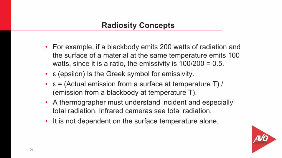
• For example, if a blackbody emits 200 watts of radiation and the surface of a material at the same temperature emits 100 watts, since it is a ratio, the emissivity is 100/200 = 0.5.
• ε (epsilon) Is the Greek symbol for emissivity. • ε = (Actual emission from a surface at temperature T) /
(emission from a blackbody at temperature T). • A thermographer must understand incident and especially
total radiation. Infrared cameras see total radiation. • It is not dependent on the surface temperature alone.
Radiosity Concepts
31
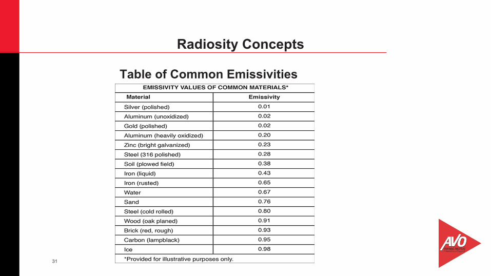
Table of Common Emissivities
Radiosity Concepts
32
• Emitted radiation depends on the temperature of the target and also the emissivity of the target (efficiency of the target to radiate).
• The emitted radiation is not the same as total radiation. • The emitted radiation is part of the total radiation and in
some cases may only be a small part of the total radiation. • Confusing the total radiation with the emitted radiation can
cause errors in temperature measurements and thermal pattern recognition.
• If the target is a poor emitter, as an example with efficiency of 20%, it would be said it had an emissivity of 0.2
Radiosity Concepts
33
• This would mean that the emitted radiation is only a small percentage of the total radiation.
• The rest is due to reflections and transmissions. • These other radiation sources need to be taken into account
in order to get an accurate temperature measurement. • A low emissivity target has high reflectivity and is like an
infrared mirror; it will indicate the apparent temperature of the energy reflecting off of it.
• A high emissivity target will better indicate the true temperature of the target.
Radiosity Concepts
34
• A thermal infrared camera detects infrared energy and converts it into an electronic signal, which is then processed to produce a thermal image and perform temperature calculations.
• Thermal imaging cameras have lenses, just like visible light cameras
• Many IR cameras can compensate for atmospheric attenuation.
• Settings can be entered for distance, relative humidity and air temperature.
• These settings correct for atmosphere and not for the size of the object.
Operating Infrared Equipment
35
• The auto image adjust function changes the level and span (thermal brightness and thermal contrast) of an infrared image to better suit the thermal characteristics of the image.
• Temperature range refers to the maximum and minimum temperatures where valid data can be saved.
• The temperatures that will be measured must be within the range setting chosen for the image after accounting for emissivity, for the best results use the smallest range available for the object being imaged.
• Span is the section within the temperature range seen on the screen.
Operating Infrared Equipment

36
• Just like with any kind of camera, the infrared image must be optically focused.
• An unfocused image looks unprofessional and can produce incorrect measurements.
• Good focus is critical to temperature measurement. • If the camera is closer than the minimum focus distance of
the lens, it will not be able to focus, and it needs to be farther away until the target is in focus.
Operating Infrared Equipment
37
• Using the measurement tools: • The spot tool is probably the most used measurement device. • It is represented by a cross hair that can be moved around the
image, and the temperatures are displayed on the image. • The isotherm tool is the oldest measurement tool. • It appears in the earliest measurement cameras from the 1960’s. • An isotherm is a measurement tool highlighting areas of the same
thermal radiation intensity.
Operating Infrared Equipment
38
• The isotherm replaces certain colors in the scale with a contrasting one, has a width and temperature level and can be moved and stretched up and down in the scale.
• The area tool allows extraction of the highest, lowest or average temperature in rectangular or circular area that can be sized and moved about the image.
• Most infrared cameras are supplied with several color palettes. • There is no right or wrong palette for any particular application.
Operating Infrared Equipment
39
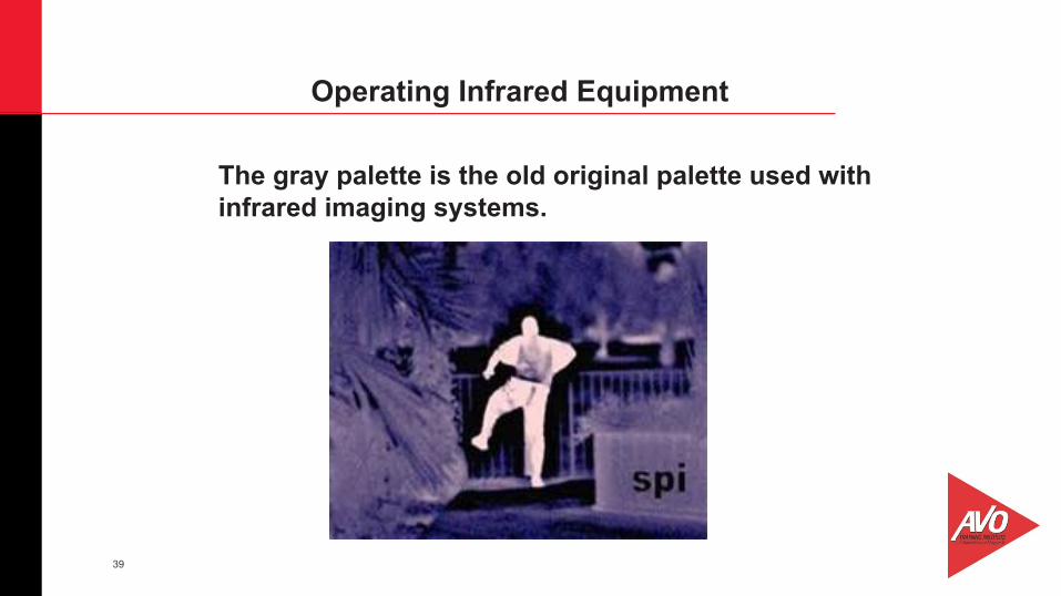
The gray palette is the old original palette used with infrared imaging systems.
Operating Infrared Equipment
40
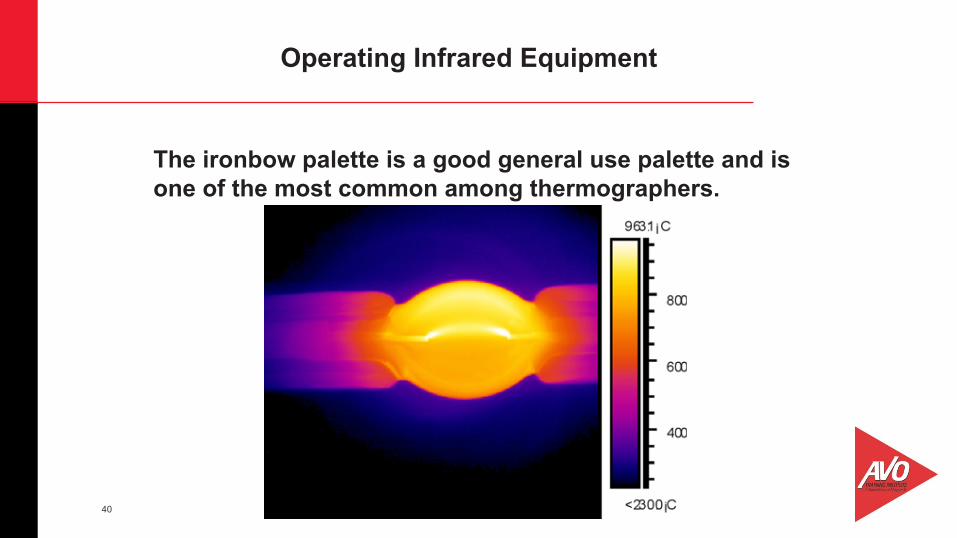
The ironbow palette is a good general use palette and is one of the most common among thermographers.
Operating Infrared Equipment
41
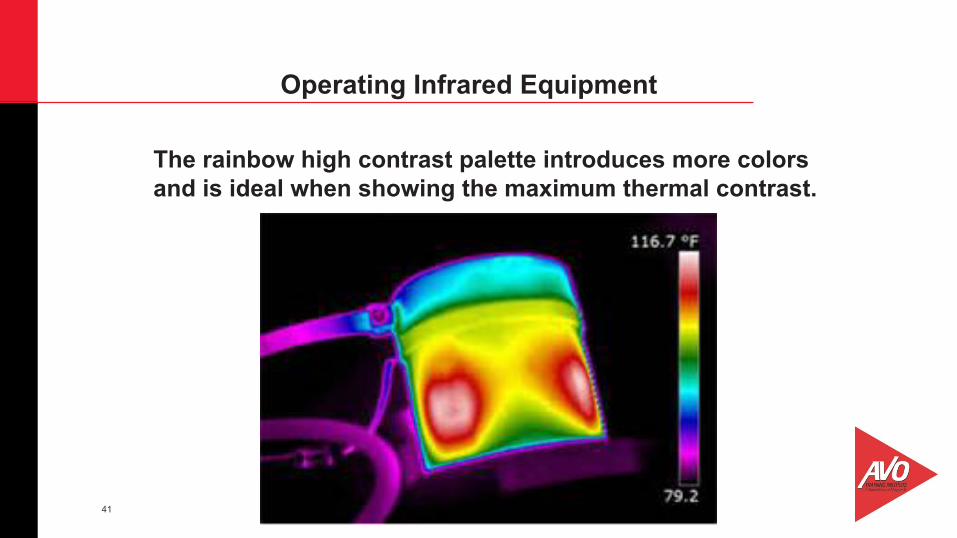
The rainbow high contrast palette introduces more colors and is ideal when showing the maximum thermal contrast.
Operating Infrared Equipment
42
• Preparing for the survey, making it as efficient as possible, is the first step in making a quality job of the survey.
• Performing the survey itself is the second part of the survey, knowing how to make the best use of time and be safe in the process.
• The final step in a good infrared survey is the report: why reports are done, what type of report is needed, and what elements make a good quality report.
• SAFETY FIRST should always be the priority on any infrared survey.
Infrared Survey and Reporting
43
• Know the surroundings, what is dangerous and how to avoid those dangers.
• An Observer or chaperon may be needed. • If a critical problem is found, freeze the image and leave the
area. • The frozen image can be used to show maintenance staff
what and where the problem is. • Thermal tuning is the procedure where the level and span is
adjusted to have the minimum span set so the targets can be seen in their ambient environment and the problem targets are readily apparent.
Infrared Survey and Reporting
44
• If the level and span is too wide, the target will appear washed out.
• Indirect targets such as control cabinets, where not all of the components (electromagnetic coils, contactors and electrical terminal boards) are visible, small temperature rises can be critical.
• Install IR windows in compartment doors and enclosed equipment where opening them can cause a hazard.
• Reports document the problems that are found during the survey and to assist maintenance personnel in the repair.
Infrared Survey and Reporting
45
• Reports can be used to track problems that are slowly developing over time.
• Using severity criteria the urgency of the repair can be categorized and used to schedule maintenance.
• Generally two types of reports that most will use: • Baseline and Exception • Base line would be the report to which all subsequent
findings are compared.
Infrared Survey and Reporting
46
• The possibilities for the uses of thermography are too numerous to address in the time allocated for this Webinar.
• Thermographers should constantly be looking for ways to use their skill and continually expand their knowledge.
• An electrical survey cannot begin without addressing SAFETY!
• Safety is first for, the thermographer and anyone assisting. • To say that one is doing an electrical inspection covers a lot
of areas • It could be, an outdoor EHV substation or as small as a
printed circuit board.
Applications of Thermography
47
• Systematically survey the facility, start with the source • Go through the circuitry to final load • Inspect all electrical terminations and splices, both bolted
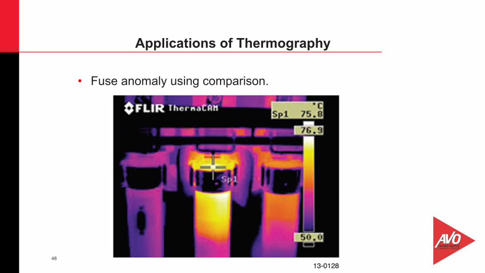
and compression. • One of the best tools that the thermographer can use in the
field is a comparison • IR windows can be installed to facilitate seeing inside
without opening the compartment and exposing the thermographer to dangerous voltages.
Applications of Thermography
48
• Fuse anomaly using comparison.
Applications of Thermography
49
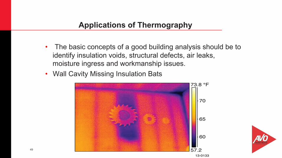
• The basic concepts of a good building analysis should be to identify insulation voids, structural defects, air leaks, moisture ingress and workmanship issues.
• Wall Cavity Missing Insulation Bats
Applications of Thermography
50
• Mechanical systems cover a wide array of devices and systems, gearboxes, belts, bearings, hoses, conveyors, hydraulic systems, air systems, HVAC systems and more.
• Since thermography is non-contact the equipment does not have to be taken out of service for the survey, and the scan can be done fast.
• The results of the scan can be visually shared with the repair technicians.
Applications of Thermography
51
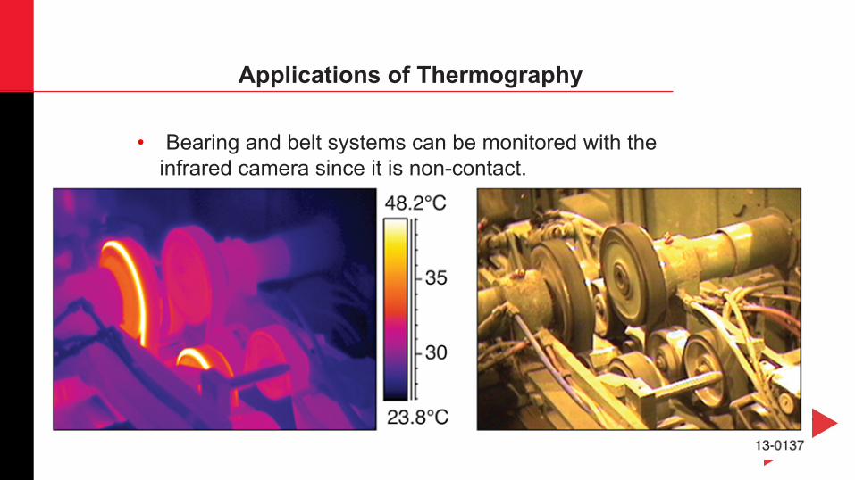
• Bearing and belt systems can be monitored with the infrared camera since it is non-contact.
Applications of Thermography
52
• We discussed the definition and history of Infrared Thermography as well as the basics of why Infrared Thermography works and examined some of the uses of Thermography.
• We addressed the concepts of heat and temperature. • We learned about heat transfer modes and radiosity
concepts. • Then we looked at some of the applications of
Thermography and operating Infrared equipment. • Infrared Thermography should be another valuable tool in
the tool box.
Summary
53
Save the Date for Our Next Webinar
Tuesday August 21, 2018 at 1pm – 2pm CDT Title: “Circuit Breaker Fundamentals - NETA Standards”
Presented by: Mike Carter AVO Training Institute, AVO Training Specialist
54
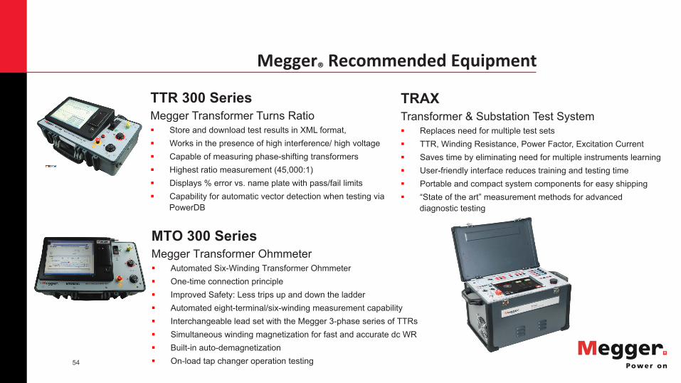
Megger®RecommendedEquipment
MTO 300 Series Megger Transformer Ohmmeter § Automated Six-Winding Transformer Ohmmeter § One-time connection principle § Improved Safety: Less trips up and down the ladder § Automated eight-terminal/six-winding measurement capability § Interchangeable lead set with the Megger 3-phase series of TTRs § Simultaneous winding magnetization for fast and accurate dc WR § Built-in auto-demagnetization § On-load tap changer operation testing
TRAX Transformer & Substation Test System § Replaces need for multiple test sets § TTR, Winding Resistance, Power Factor, Excitation Current § Saves time by eliminating need for multiple instruments learning § User-friendly interface reduces training and testing time § Portable and compact system components for easy shipping § “State of the art” measurement methods for advanced
diagnostic testing
TTR 300 Series Megger Transformer Turns Ratio § Store and download test results in XML format, § Works in the presence of high interference/ high voltage § Capable of measuring phase-shifting transformers § Highest ratio measurement (45,000:1) § Displays % error vs. name plate with pass/fail limits § Capability for automatic vector detection when testing via
PowerDB
55
AVORecommendedCourses
Infrared Thermography Level I Certification 4.5 Days – 3.6 CEUs Infrared Thermography Level II Certification 4.5 Days – 3.6 CEUs
Click for Course Catalog Download
www.avotraining.com

56
Megger®RecommendedEquipment
MTO 300 Series Megger Transformer Ohmmeter § Automated Six-Winding Transformer Ohmmeter § One-time connection principle § Improved Safety: Less trips up and down the ladder § Automated eight-terminal/six-winding measurement capability § Interchangeable lead set with the Megger 3-phase series of TTRs § Simultaneous winding magnetization for fast and accurate dc WR § Built-in auto-demagnetization § On-load tap changer operation testing
TRAX Transformer & Substation Test System § Replaces need for multiple test sets § TTR, Winding Resistance, Power Factor, Excitation Current § Saves time by eliminating need for multiple instruments learning § User-friendly interface reduces training and testing time § Portable and compact system components for easy shipping § “State of the art” measurement methods for advanced
diagnostic testing
TTR 300 Series Megger Transformer Turns Ratio § Store and download test results in XML format, § Works in the presence of high interference/ high voltage § Capable of measuring phase-shifting transformers § Highest ratio measurement (45,000:1) § Displays % error vs. name plate with pass/fail limits § Capability for automatic vector detection when testing via
PowerDB
57
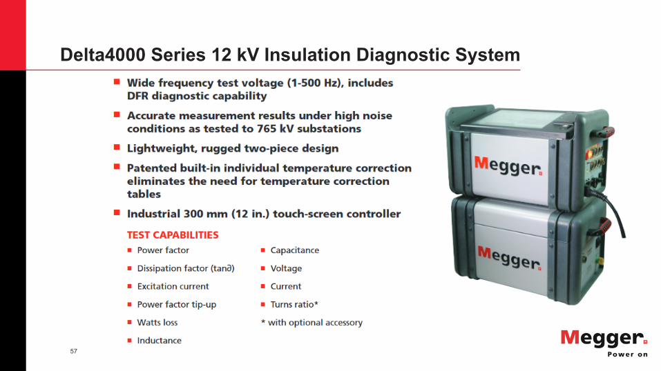
Delta4000 Series 12 kV Insulation Diagnostic System

58
Questions? After more than 50 years, AVO Training remains a global leader in safety and maintenance training for the electrical industry. We deliver an engaging, hands-on experience for our clients in a professional, real-world environment. We strive to provide industry relevant courses in a practical and flexible learning environment through an ongoing commitment to quality service, integrity, instruction, and client satisfaction. Our goal is to convey practical job skills and career development for our clients and students by saving lives through a world-class learning experience.
© AVO Training Institute, Inc. 2018