Basic Technical Information For 2014 Samsung Heat · PDF fileBasic Technical Information For...
40
Basic Technical Information For 2014 Samsung Heat Pump Inverter Mini Splits Quietside West Quietside Central Quietside East 8750 Pioneer Blvd 3001 Northern Cross Blvd. 6 Pine Hill Dr Santa Fe Springs CA 90670 Suite #361 Carlisle PA 17013 Fort Worth, TX 76137 Web : www.quietside.com SAM-BT14-001
Transcript of Basic Technical Information For 2014 Samsung Heat · PDF fileBasic Technical Information For...

Basic Technical Information
For 2014 Samsung
Heat Pump Inverter Mini Splits
Quietside West Quietside Central Quietside East 8750 Pioneer Blvd 3001 Northern Cross Blvd. 6 Pine Hill Dr Santa Fe Springs CA 90670 Suite #361 Carlisle PA 17013 Fort Worth, TX 76137
Web : www.quietside.com SAM-BT14-001

www.quietside.com
CONTENTS
Page Description
3 AR09HSFSHWKNCV 4 AR12HSFSHWKNCV 5 AR18HSFSHWKNCV 6 AR24HSFSHWKNCV 7 AQN09VFUAGM 8 AQN12VFUAGM 9 AQN18VFUAGM 10 AQN24VFUAGM 11 AQN36VFUAGM 12 Max/Whisper Wired Controller Option 13 MIM-A00A Supplemental Installation Instructions 14 MIM-A00A Supplemental Installation Instructions 15 MIM-A00A Supplemental Installation Instructions 16 EH035CAV 17 EH052CAV 18 EH070CAV 19 EH Model Series Rotary & Dip Switch Settings 20 DH105CAV 21 DH140CAV 22 DH Model Series Rotary & Dip Switch Settings 23 CH070CAV1 24 CH105CAV 25 CH140CAV 26 CH Model Series Rotary & Dip Switch Settings 27 MH050FXCA2A 28 MH080FXCA4A 29 MH026FNCA & MH035FNCA 30 MH052FNCA 31 MH026FECA & MH035FECA 32 MH052FECA 33 NJ030MHXCA & NJ035MHXCA 34 NJ052MHXCA 35 NJ0261HXCA & NJ0351HXCA 36 FJM (MH) Model Series Systems Auto Addressing 37 FJM (MH) Model Series Systems Manual Addressing 38 Installation Tips – Refrigeration 39 Basic Installation Tips 40 Basic Installation Tips
Due to Samsung’s ongoing development policy specifications and information are subject to change without notice

www.quietside.com
3
AR09HSFSHWKNCV Heat Pump Mini Split
Indoor Unit : AR09HSFSHWKNCV Outdoor Unit : AR09HSFSHWKXCV Power
Power Voltage : 208/230V – 1 Ph – 60 Hz
Control Voltage : DDC Fuzzy Logic
Main Breaker Size : 15 A
Line Sizes :
“Liquid” (expanded gas) line 1/4”
Suction 3/8”
BOTH LINES MUST BE INSULATED SEPARATELY Interconnect Length
Maximum / Minimum Length 50 / 10 feet
Vertical lift 26 feet
(Note condenser can be above or below evaporator) Charging
Unit is charged for 25 ft (Factory Charge 44.1oz R410A)
Additional Charge of R410A 0.16oz/ft over 25ft
Charge for Line Run lengths
Length 25 35 45 50
Added Charge (oz) 0 1.6 3.3 4.0
Interconnecting Wiring
Gauge 14 AWG Power &16 AWG Shielded Communication
Number of Interconnecting Wires 3x14 AWG Power & 2x16 AWG Control = 5 Total

www.quietside.com
4
AR12HSFSHWKNCV Heat Pump Mini Split
Indoor Unit : AR12HSFSHWKNCV Outdoor Unit : AR12HSFSHWKXCV Power
Power Voltage : 208/230V – 1 Ph – 60 Hz
Control Voltage : DDC Fuzzy Logic
Main Breaker Size : 15 A
Line Sizes :
“Liquid” (expanded gas) line 1/4”
Suction 3/8”
BOTH LINES MUST BE INSULATED SEPARATELY Interconnect Length
Maximum / Minimum Length 50 / 10 feet
Vertical lift 26 feet
(Note condenser can be above or below evaporator) Charging
Unit is charged for 25 ft (Factory Charge 44.1oz R410A)
Additional Charge of R410A 0.16oz/ft over 25ft
Charge for Line Run lengths
Length 25 35 45 50
Added Charge (oz) 0 1.6 3.3 4.0
Interconnecting Wiring
Gauge 14 AWG Power &16 AWG Shielded Communication
Number of Interconnecting Wires 3x14 AWG Power & 2x16 AWG Control = 5 Total
www.quietside.com
5
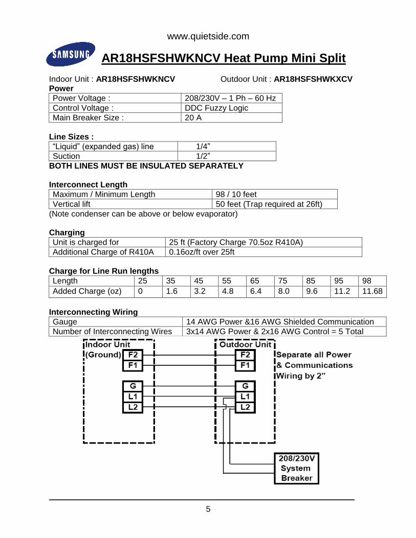
AR18HSFSHWKNCV Heat Pump Mini Split
Indoor Unit : AR18HSFSHWKNCV Outdoor Unit : AR18HSFSHWKXCV Power
Power Voltage : 208/230V – 1 Ph – 60 Hz
Control Voltage : DDC Fuzzy Logic
Main Breaker Size : 20 A
Line Sizes :
“Liquid” (expanded gas) line 1/4”
Suction 1/2”
BOTH LINES MUST BE INSULATED SEPARATELY Interconnect Length
Maximum / Minimum Length 98 / 10 feet
Vertical lift 50 feet (Trap required at 26ft)
(Note condenser can be above or below evaporator) Charging
Unit is charged for 25 ft (Factory Charge 70.5oz R410A)
Additional Charge of R410A 0.16oz/ft over 25ft
Charge for Line Run lengths
Length 25 35 45 55 65 75 85 95 98
Added Charge (oz) 0 1.6 3.2 4.8 6.4 8.0 9.6 11.2 11.68
Interconnecting Wiring
Gauge 14 AWG Power &16 AWG Shielded Communication
Number of Interconnecting Wires 3x14 AWG Power & 2x16 AWG Control = 5 Total

www.quietside.com
6
AR24HSFSHWKNCV Heat Pump Mini Split
Indoor Unit : AR24HSFSHWKNCV Outdoor Unit : AR24HSFSHWKXCV Power
Power Voltage : 208/230V – 1 Ph – 60 Hz
Control Voltage : DDC Fuzzy Logic
Main Breaker Size : 30 A
Line Sizes :
“Liquid” (expanded gas) line 1/4”
Suction 5/8”
BOTH LINES MUST BE INSULATED SEPARATELY Interconnect Length
Maximum / Minimum Length 164 / 10 feet
Vertical lift 98 feet (Trap required at 26ft)
(Note condenser can be above or below evaporator) Charging
Unit is charged for 25 ft (Factory Charge 81.1oz R410A)
Additional Charge of R410A 0.43oz/ft over 25ft
Charge for Line Run lengths
Length 25 35 45 55 65 75 85 95 98
Added Charge (oz) 0 4.3 8.6 12.9 17.2 21.5 25.8 30.1 31.39
Interconnecting Wiring
Gauge 14 AWG Power &16 AWG Shielded Communication
Number of Interconnecting Wires 3x14 AWG Power & 2x16 AWG Control = 5 Total
www.quietside.com
7
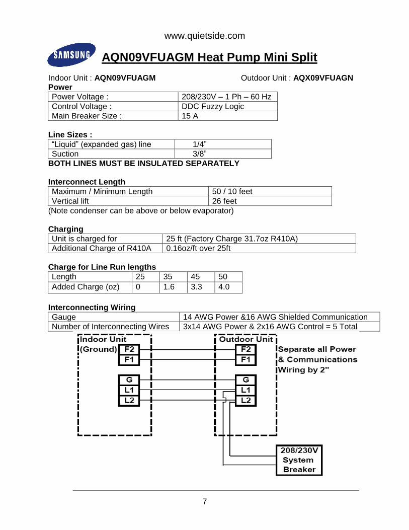
AQN09VFUAGM Heat Pump Mini Split
Indoor Unit : AQN09VFUAGM Outdoor Unit : AQX09VFUAGN Power
Power Voltage : 208/230V – 1 Ph – 60 Hz
Control Voltage : DDC Fuzzy Logic
Main Breaker Size : 15 A
Line Sizes :
“Liquid” (expanded gas) line 1/4”
Suction 3/8”
BOTH LINES MUST BE INSULATED SEPARATELY Interconnect Length
Maximum / Minimum Length 50 / 10 feet
Vertical lift 26 feet
(Note condenser can be above or below evaporator) Charging
Unit is charged for 25 ft (Factory Charge 31.7oz R410A)
Additional Charge of R410A 0.16oz/ft over 25ft
Charge for Line Run lengths
Length 25 35 45 50
Added Charge (oz) 0 1.6 3.3 4.0
Interconnecting Wiring
Gauge 14 AWG Power &16 AWG Shielded Communication
Number of Interconnecting Wires 3x14 AWG Power & 2x16 AWG Control = 5 Total
www.quietside.com
8
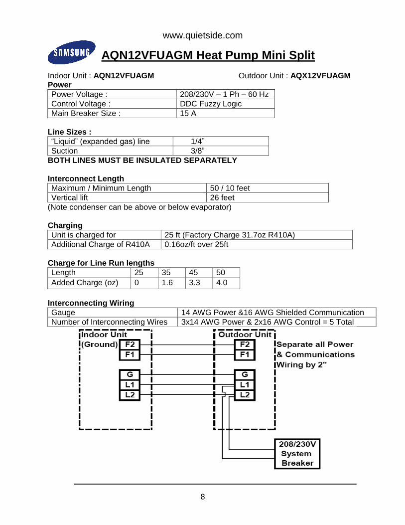
AQN12VFUAGM Heat Pump Mini Split
Indoor Unit : AQN12VFUAGM Outdoor Unit : AQX12VFUAGM Power
Power Voltage : 208/230V – 1 Ph – 60 Hz
Control Voltage : DDC Fuzzy Logic
Main Breaker Size : 15 A
Line Sizes :
“Liquid” (expanded gas) line 1/4”
Suction 3/8”
BOTH LINES MUST BE INSULATED SEPARATELY Interconnect Length
Maximum / Minimum Length 50 / 10 feet
Vertical lift 26 feet
(Note condenser can be above or below evaporator) Charging
Unit is charged for 25 ft (Factory Charge 31.7oz R410A)
Additional Charge of R410A 0.16oz/ft over 25ft
Charge for Line Run lengths
Length 25 35 45 50
Added Charge (oz) 0 1.6 3.3 4.0
Interconnecting Wiring
Gauge 14 AWG Power &16 AWG Shielded Communication
Number of Interconnecting Wires 3x14 AWG Power & 2x16 AWG Control = 5 Total
www.quietside.com
9
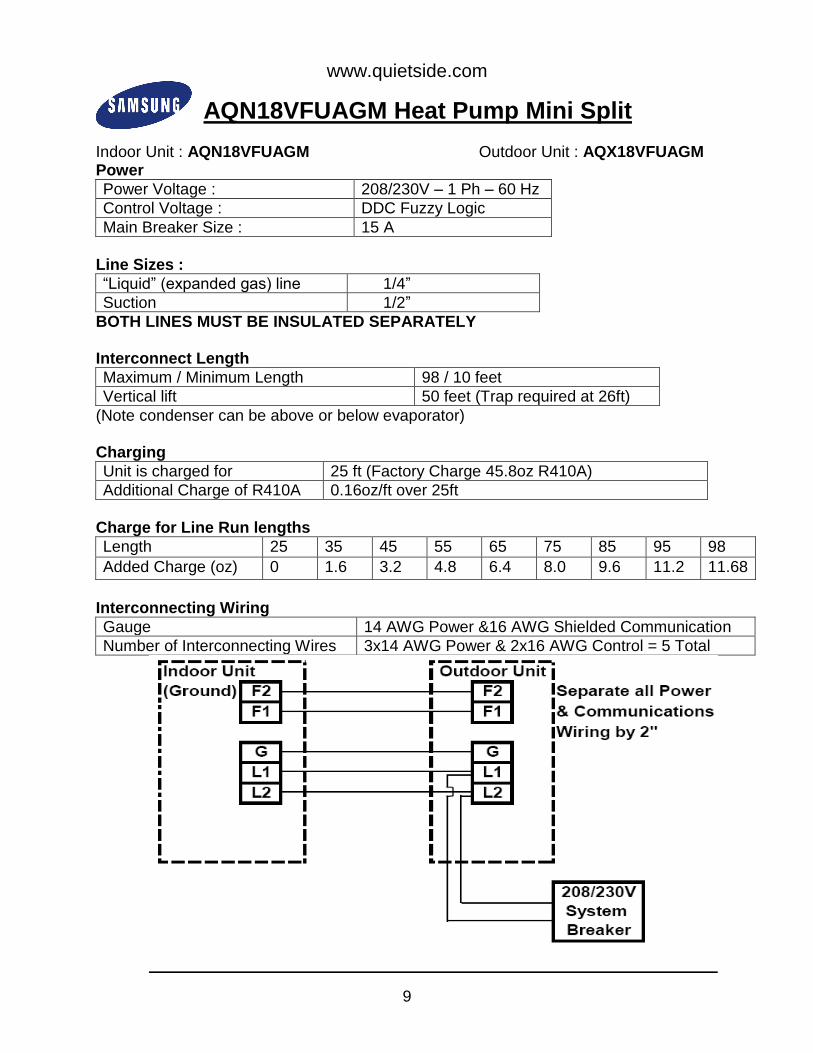
AQN18VFUAGM Heat Pump Mini Split
Indoor Unit : AQN18VFUAGM Outdoor Unit : AQX18VFUAGM Power
Power Voltage : 208/230V – 1 Ph – 60 Hz
Control Voltage : DDC Fuzzy Logic
Main Breaker Size : 15 A
Line Sizes :
“Liquid” (expanded gas) line 1/4”
Suction 1/2”
BOTH LINES MUST BE INSULATED SEPARATELY Interconnect Length
Maximum / Minimum Length 98 / 10 feet
Vertical lift 50 feet (Trap required at 26ft)
(Note condenser can be above or below evaporator) Charging
Unit is charged for 25 ft (Factory Charge 45.8oz R410A)
Additional Charge of R410A 0.16oz/ft over 25ft
Charge for Line Run lengths
Length 25 35 45 55 65 75 85 95 98
Added Charge (oz) 0 1.6 3.2 4.8 6.4 8.0 9.6 11.2 11.68
Interconnecting Wiring
Gauge 14 AWG Power &16 AWG Shielded Communication
Number of Interconnecting Wires 3x14 AWG Power & 2x16 AWG Control = 5 Total

www.quietside.com
10
AQN24VFUAGM Heat Pump Mini Split
Indoor Unit : AQN24VFUAGM Outdoor Unit : AQX24VFUAGM Power
Power Voltage : 208/230V – 1 Ph – 60 Hz
Control Voltage : DDC Fuzzy Logic
Main Breaker Size : 20 A
Line Sizes :
“Liquid” (expanded gas) line 1/4”
Suction 5/8”
BOTH LINES MUST BE INSULATED SEPARATELY Interconnect Length
Maximum / Minimum Length 98 /10 feet
Vertical lift 50 feet (Trap required at 26ft)
(Note condenser can be above or below evaporator) Charging
Unit is charged for 25 ft (Factory Charge 58.1oz R410A)
Additional Charge of R410A 0.16oz/ft over 25ft
Charge for Line Run lengths
Length 25 35 45 55 65 75 85 95 98
Added Charge (oz) 0 1.6 3.2 4.8 6.4 8.0 9.6 11.2 11.68
Interconnecting Wiring
Gauge 14 AWG Power &16 AWG Shielded Communication
Number of Interconnecting Wires 3x14 AWG Power & 2x16 AWG Control = 5 Total

www.quietside.com
11
AQN36VFUAGM Heat Pump Mini Split
Indoor Unit : AQN36VFUAGM Outdoor Unit : AQX36VFUAGM Power
Power Voltage : 208/230V – 1 Ph – 60 Hz
Control Voltage : DDC Fuzzy Logic
Main Breaker Size : 30 A
Line Sizes :
“Liquid” (expanded gas) line 1/4”
Suction 5/8”
BOTH LINES MUST BE INSULATED SEPARATELY Interconnect Length
Maximum / Minimum Length 164 / 10 feet
Vertical lift 98 feet (Trap required at 26ft)
(Note condenser can be above or below evaporator) Charging
Unit is charged for 25 ft (Factory Charge 88.1oz R410A)
Additional Charge of R410A 0.43oz/ft over 25ft
Charge for Line Run lengths
Length 25 35 45 55 65 75 85 95 100
Added Charge (oz) 0 4.3 8.6 12.9 17.2 21.5 25.8 30.1 32.25
Interconnecting Wiring
Gauge 14 AWG Power &16 AWG Shielded Communication
Number of Interconnecting Wires 3x14 AWG Power & 2x16 AWG Control = 5 Total

www.quietside.com
12
MAX/Whisper Wired Controller Option* *MIM-A00A Supplemental Installation Instructions
Sub-PCB Sub-PCB Wire Harness
• The MIM-A00A sub-PCB installs inside a single MAX indoor unit (AQN**VFUAGM models). It is required to connect and control an indoor unit with wired controller models MWR-WH00 or MWRWE10 • Provides 12V DC to Samsung wired controllers • Required to control AQN**VFUAGM models with Samsung central control options (upper level control) • Includes sub-PCB, crimp wire connectors (4), wire harness, and sub-PCB cover
MAX

www.quietside.com
13
MIM-A00A Supplemental Installation Instructions
Note: RED = F3, BLUE = F4, ORANGE= V1, YELLOW = V2

www.quietside.com
14
MIM-A00A Supplemental Installation Instructions
Whisper

www.quietside.com
15
Wire Diagrams .
MAX Whisper
NOTE: MWR-WH00 wired controllers ship with color coded connection wires (≈ 32’). MWR-WE10 wired controllers do not include connection wire. This wire is field provided
www.quietside.com
16
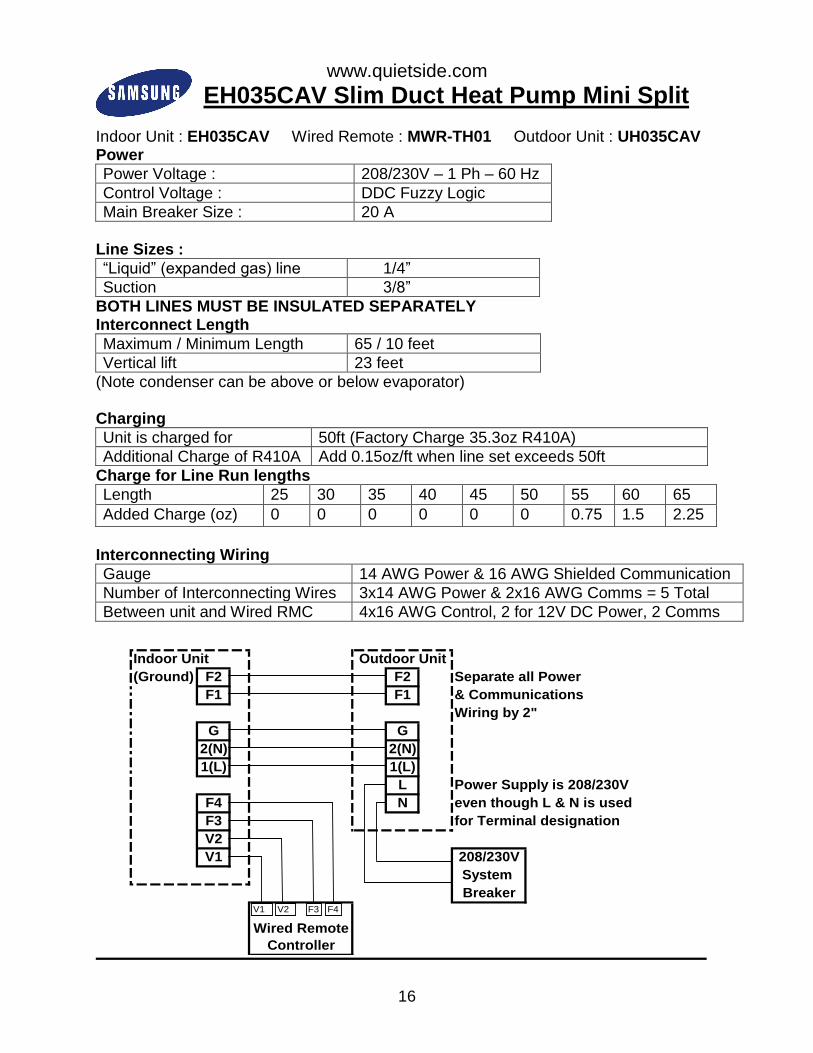
EH035CAV Slim Duct Heat Pump Mini Split
Indoor Unit : EH035CAV Wired Remote : MWR-TH01 Outdoor Unit : UH035CAV Power
Power Voltage : 208/230V – 1 Ph – 60 Hz
Control Voltage : DDC Fuzzy Logic
Main Breaker Size : 20 A
Line Sizes :
“Liquid” (expanded gas) line 1/4”
Suction 3/8”
BOTH LINES MUST BE INSULATED SEPARATELY Interconnect Length
Maximum / Minimum Length 65 / 10 feet
Vertical lift 23 feet
(Note condenser can be above or below evaporator) Charging
Unit is charged for 50ft (Factory Charge 35.3oz R410A)
Additional Charge of R410A Add 0.15oz/ft when line set exceeds 50ft
Charge for Line Run lengths
Length 25 30 35 40 45 50 55 60 65
Added Charge (oz) 0 0 0 0 0 0 0.75 1.5 2.25
Interconnecting Wiring
Gauge 14 AWG Power & 16 AWG Shielded Communication
Number of Interconnecting Wires 3x14 AWG Power & 2x16 AWG Comms = 5 Total
Between unit and Wired RMC 4x16 AWG Control, 2 for 12V DC Power, 2 Comms
Indoor Unit Outdoor Unit
(Ground) F2 F2 Separate all Power
F1 F1 & Communications
Wiring by 2"
G G
2(N) 2(N)
1(L) 1(L)
L Power Supply is 208/230V
F4 N even though L & N is used
F3 for Terminal designation
V2
V1 208/230V
System
Breaker
Wired Remote
Controller
V2 F3 F4V1

www.quietside.com
17
EH052CAV Slim Duct Heat Pump Mini Split
Indoor Unit : EH052CAV Wired Remote : MWR-TH01 Outdoor Unit : UH052CAV Power
Power Voltage : 208/230V – 1 Ph – 60 Hz
Control Voltage : DDC Fuzzy Logic
Main Breaker Size : 25 A
Line Sizes :
“Liquid” (expanded gas) line 1/4”
Suction 1/2”
BOTH LINES MUST BE INSULATED SEPARATELY Interconnect Length
Maximum / Minimum Length 98 / 10 feet
Vertical lift 49 feet (Trap required at 26ft)
(Note condenser can be above or below evaporator) Charging
Unit is charged for 25 ft (Factory Charge 51.1oz R410A)
Additional Charge of R410A 0.2oz per ft over 25ft
Charge for Line Run lengths
Length 25 35 45 55 65 75 85 95 98
Added Charge (oz) 0 2.0 4.0 6.0 8.0 10.0 12.0 14.0 14.6
Interconnecting Wiring
Gauge 14 AWG Power &16 AWG Shielded Communication
Number of Interconnecting Wires 3x14 AWG Power & 2x16 AWG Comms = 5 Total
Between unit and Wired RMC 4x16 AWG Control, 2 for 12V DC Power, 2 Comms
Indoor Unit Outdoor Unit
(Ground) F2 F2 Separate all Power
F1 F1 & Communications
Wiring by 2"
G G
2(N) 2(N)
1(L) 1(L)
L Power Supply is 208/230V
F4 N even though L & N is used
F3 for Terminal designation
V2
V1 208/230V
System
Breaker
Wired Remote
Controller
V2 F3 F4V1

www.quietside.com
18
EH070CAV Slim Duct Heat Pump Mini Split
Indoor Unit : EH070CAV Wired Remote : MWR-TH01 Outdoor Unit : UH070CAV Power
Power Voltage : 208/230V – 1 Ph – 60 Hz
Control Voltage : DDC Fuzzy Logic
Main Breaker Size : 30 A
Line Sizes :
“Liquid” (expanded gas) line 1/4”
Suction 5/8”
BOTH LINES MUST BE INSULATED SEPARATELY Interconnect Length
Maximum / Minimum Length 98 / 10 feet
Vertical lift 49 feet (Trap required at 26ft)
(Note condenser can be above or below evaporator)
Charging
Unit is charged for 25 ft (Factory Charge 67oz R410A)
Additional Charge of R410A 0.1oz per ft over 25ft
Charge for Line Run lengths
Length 25 35 45 55 65 75 85 95 98
Added Charge (oz) 0 1.0 2.0 3.0 4.0 5.0 6.0 7.0 8.0
Interconnecting Wiring
Gauge 14 AWG Power &16 AWG Shielded Communication
Number of Interconnecting Wires 3x14 AWG Power & 2x16 AWG Comms = 5 Total
Between unit and Wired RMC 4x16 AWG Control, 2 for 12V DC Power, 2 Comms
Indoor Unit Outdoor Unit
(Ground) F2 F2 Separate all Power
F1 F1 & Communications
Wiring by 2"
G G
2(N) 2(N)
1(L) 1(L)
L Power Supply is 208/230V
F4 N even though L & N is used
F3 for Terminal designation
V2
V1 208/230V
System
Breaker
Wired Remote
Controller
V2 F3 F4V1

www.quietside.com
19
EH Model Series Rotary Switch Settings
Indoor unit Dip Switch Settings - EH Model Series
The correct setting of the Indoor PCB Dip Switches and the Dip Switches is required Indoor Unit Dip Switches are all set in the ON position as the Factory Default Depending on the application certain switches must be set to the OFF position to allow use of an option, or specific control feature USE OF THE WIRED REMOTE CONTROL IS STANDARD, THE #1 DIP SWITCH ON SW05 OF THE MAIN PCB OF THE INDOOR UNIT MUST BE SWITCHED TO THE OFF POSITION BEFORE STARTING THE UNIT Samsung recommend altering Dip switches prior to mounting the Indoor unit Switch #'s read Left to Right, count to ensure the correct one is switched as they are all labeled 1-4
Indoor Unit
Switch# Controls Action Setting
SW
05 1 Use of Wired Remote Switch to OFF if Wired Remote is used OFF
2 Central Control/SNET Switch to OFF if Central/SNET option is used ON
3 Not used on this unit Ignore ON
4 Condensate Pump Switch to OFF if Samsung Pump is installed ON
SW
06 1 Temp Compensation Switch to OFF to compensate for duct heat gain ON
2 Filter Timer Light Switch to OFF to increase time for filter change ON
3 Hot Water Coil Contact Factory to discuss auxiliary heat option ON
4 Not used on this unit Ignore ON
SW
07 1 Not used on this unit Ignore ON
2 Not used on this unit Ignore ON
3 Remote On/Off control Switch to OFF to allow external control of unit ON
4 Not used on this unit Ignore ON
MWR-TH01 Wired Remote Control K1 Heat Pump/Cooling Only Switch to ON for Heat Pump operation ON
K2 Use of F3/F4 or F1/F2 Switch to OFF as unit uses F3 - F4 Comms OFF
K3 Display DegC or DegF Switch to ON for DegF Display ON
K4 Wired/Wireless Control Switch to OFF to allow use of both controls ON
K5 Not used on this unit Ignore N/A
K6 Not used on this unit Ignore N/A
K7 Not used on this unit Ignore N/A
K8 Not used on this unit Ignore N/A
After every Dip Switch change the power to the system must be turned off for 3 minutes
to allow the unit to recognize the changes to the Dip Switch settings

www.quietside.com
20
DH105CAV MSP Duct Heat Pump
Indoor Unit : DH105CAV Wired Remote : MWR-WE10 Outdoor Unit : UH105CAV Power
Power Voltage : 208/230V – 1 Ph – 60 Hz
Control Voltage : DDC Fuzzy Logic
Main Breaker Size : 35 A
Line Sizes :
“Liquid” (expanded gas) line 3/8”
Suction 5/8”
BOTH LINES MUST BE INSULATED SEPARATELY Interconnect Length
Maximum / Minimum Length 246 / 10 feet
Vertical lift 98 feet (Trap required every 50ft)
(Note condenser can be above or below evaporator)
Charging
Unit is charged for 25 ft (Factory Charge 98.8oz R410A)
Additional Charge of R410A 0.4oz per ft over 25ft
Charge for Line Run lengths
Length 25 45 65 85 105 125 150 175 200
Added Charge (oz) 0 8.0 18.0 24.0 32.0 40.0 50.0 60.0 70.0
Interconnecting Wiring
Gauge 14 AWG Power &16 AWG Shielded Communication
Number of Interconnecting Wires 3x14 AWG Power & 2x16 AWG Coms = 5 Total
Between unit and Wired RMC 2 sets of 2x16 AWG Control, for 12VDC Power, Coms
Indoor Unit Outdoor Unit
(Ground) F2 F2 Separate all Power
F1 F1 & Communications
Wiring by 2"
G G
2(N) 2(N)
1(L) 1(L)
L Power Supply is 208/230V
F4 N even though L & N is used
F3 for Terminal designation
V2
V1 208/230V
System
Breaker
Wired Remote
Controller
V2 F3 F4V1

www.quietside.com
21
DH140CAV MSP Duct Heat Pump
Indoor Unit : DH140CAV Wired Remote : MWR-WE10 Outdoor Unit : UH140CAV Power
Power Voltage : 208/230V – 1 Ph – 60 Hz
Control Voltage : DC Fuzzy Logic
Main Breaker Size : 50 A
Line Sizes :
“Liquid” (expanded gas) line 3/8”
Suction 3/4”
BOTH LINES MUST BE INSULATED SEPARATELY Interconnect Length
Maximum / Minimum Length 246 /10 feet
Vertical lift 98 feet (Trap required at 26ft)
(Note condenser can be above or below evaporator) Charging
Unit is charged for 25 ft (Factory Charge 98.8oz R410A)
Additional Charge of R410A 0.4oz per ft over 25ft
Charge for Line Run lengths
Length 25 45 65 85 105 125 150 175 200
Added Charge (oz) 0 8.0 18.0 24.0 32.0 40.0 50.0 60.0 70.0
Interconnecting Wiring
Gauge 14 AWG Power &16 AWG Shielded Communication
Number of Interconnecting Wires 3x14 AWG Power & 2x16 AWG Coms = 5 Total
Between unit and Wired RMC 2 sets of 2x16 AWG Control, for 12VDC Power, Coms
Indoor Unit Outdoor Unit
(Ground) F2 F2 Separate all Power
F1 F1 & Communications
Wiring by 2"
G G
2(N) 2(N)
1(L) 1(L)
L Power Supply is 208/230V
F4 N even though L & N is used
F3 for Terminal designation
V2
V1 208/230V
System
Breaker
Wired Remote
Controller
V2 F3 F4V1

www.quietside.com
22
DH Model Series Rotary Switch Settings
Indoor unit Dip Switch Settings - DH Model Series
The correct setting of the Indoor PCB Dip Switches and the Dip Switches is required Indoor Unit Dip Switches are all set in the ON position as the Factory Default Depending on the application certain switches must be set to the OFF position to allow use of an option, or specific control feature USE OF THE WIRED REMOTE CONTROL IS STANDARD, THE #1 DIP SWITCH ON SW05 OF THE MAIN PCB OF THE INDOOR UNIT MUST BE SWITCHED TO THE OFF POSITION BEFORE STARTING THE UNIT Samsung recommend altering Dip switches prior to mounting the Indoor unit Switch #'s read Left to Right, count to ensure the correct one is switched as they are all labeled 1-4
Indoor Unit
Switch# Controls Action Setting
SW
05
1 Use of Wired Remote Switch to OFF if Wired Remote is used OFF
2 Central Control/SNET Switch to OFF if Central/SNET option is used ON
3 Not used on this unit Ignore ON
4 Condensate Pump Switch to OFF only if the optional Samsung Condensate Pump is installed and wired to PCB ON
SW
06 1 Temp Compensation Switch to OFF to compensate for duct heat gain ON
2 Filter Timer Light Switch to OFF to increase time for filter change ON
3 Hot Water Coil Contact Factory to discuss auxiliary heat option ON
4 Not used on this unit Ignore ON
SW
07 1 Not used on this unit Ignore ON
2 Not used on this unit Ignore ON
3 Remote On/Off control Switch to OFF to allow external control of unit ON
4 Not used on this unit Ignore ON
E620 error on start up of MWR-WE10
"E620" indicates the wired controller has a different temperature unit setting than the indoor unit. The following steps will set the controller to degF and enable it to communicate with the indoor unit.
Press and hold the "SET" and "ESC" buttons for at least 3 seconds. A flashing "1" will display (main menu)
Press (>) button – another “1” will display & flash for the sub menu
Press (>) button again to display the 4 digit “data settings” "0100" should be displayed for the “data settings”
Press the (>) until the 4th digit is flashing in the "data bit field". Press the (v) button to change that digit to “1”
"0101" should now be displayed for "data setting" Press the “SET” button, then press “ESC”

www.quietside.com
23
CH070CAV1 Cassette Heat Pump
Indoor Unit : CH070CAV1 Wired Remote : MWR-WE10 Outdoor Unit : UH070CAV1 Power
Power Voltage : 208/230V – 1 Ph – 60 Hz
Control Voltage : DC Fuzzy Logic
Main Breaker Size : 25 A
Line Sizes :
“Liquid” (expanded gas) line 1/4”
Suction 5/8”
BOTH LINES MUST BE INSULATED SEPARATELY Interconnect Length
Maximum / Minimum Length 162 / 10 feet
Vertical lift 98 feet (Trap required every 26ft)
(Note condenser can be above or below evaporator)
Charging
Unit is charged for 25 ft (Factory Charge 67oz R410A)
Additional Charge of R410A 0.1oz per ft over 25ft
Charge for Line Run lengths
Length 25 40 55 70 85 100 115 130 150
Added Charge (oz) 0 1.0 2.0 3.0 4.0 5.0 6.0 7.0 8.0
Interconnecting Wiring
Gauge 14 AWG Power &16 AWG Shielded Communication
Number of Interconnecting Wires 3x14 AWG Power & 2x16 AWG Comms = 5 Total
Between unit and Wired RMC 4x16 AWG Control, 2 for 12V DC Power, 2 Comms
Indoor Unit Outdoor Unit
(Ground) F2 F2 Separate all Power
F1 F1 & Communications
Wiring by 2"
G G
2(N) 2(N)
1(L) 1(L)
L Power Supply is 208/230V
F4 N even though L & N is used
F3 for Terminal designation
V2
V1 208/230V
System
Breaker
Wired Remote
Controller
V2 F3 F4V1

www.quietside.com
24
CH105CAV Cassette Heat Pump
Indoor Unit : CH105CAV Wired Remote : MWR-WE10 Outdoor Unit : UH105CAV Power
Power Voltage : 208/230V – 1 Ph – 60 Hz
Control Voltage : DC Fuzzy Logic
Main Breaker Size : 35 A
Line Sizes :
“Liquid” (expanded gas) line 3/8”
Suction 5/8”
BOTH LINES MUST BE INSULATED SEPARATELY Interconnect Length
Maximum / Minimum Length 246 / 10 feet
Vertical lift 98 feet (Trap required at 26ft)
(Note condenser can be above or below evaporator)
Charging
Unit is charged for 25 ft (Factory Charge 98.8oz R410A)
Additional Charge of R410A 0.4oz per ft over 25ft
Charge for Line Run lengths
Length 25 45 65 85 105 125 150 175 200
Added Charge (oz) 0 8.0 18.0 24.0 32.0 40.0 50.0 60.0 70.0
Interconnecting Wiring
Gauge 14 AWG Power &16 AWG Shielded Communication
Number of Interconnecting Wires 3x14 AWG Power & 2x16 AWG Coms = 5 Total
Between unit and Wired RMC 2 sets of 2x16 AWG Control, for 12VDC Power, Coms
Indoor Unit Outdoor Unit
(Ground) F2 F2 Separate all Power
F1 F1 & Communications
Wiring by 2"
G G
2(N) 2(N)
1(L) 1(L)
L Power Supply is 208/230V
F4 N even though L & N is used
F3 for Terminal designation
V2
V1 208/230V
System
Breaker
Wired Remote
Controller
V2 F3 F4V1

www.quietside.com
25
CH140CAV Cassette Heat Pump
Indoor Unit : CH140CAV Wired Remote : MWR-WE10 Outdoor Unit : UH105CAV Power
Power Voltage : 208/230V – 1 Ph – 60 Hz
Control Voltage : DC Fuzzy Logic
Main Breaker Size : 50 A
Line Sizes :
“Liquid” (expanded gas) line 3/8”
Suction 3/4”
BOTH LINES MUST BE INSULATED SEPARATELY Interconnect Length
Maximum / Minimum Length 246 / 10 feet
Vertical lift 98 feet (Trap required at 26ft)
(Note condenser can be above or below evaporator)
Charging
Unit is charged for 25 ft (Factory Charge 98.8oz R410A)
Additional Charge of R410A 0.4oz per ft over 25ft
Charge for Line Run lengths
Length 25 45 65 85 105 125 150 175 200
Added Charge (oz) 0 8.0 18.0 24.0 32.0 40.0 50.0 60.0 70.0
Interconnecting Wiring
Gauge 14 AWG Power &16 AWG Shielded Communication
Number of Interconnecting Wires 3x14 AWG Power & 2x16 AWG Coms = 5 Total
Between unit and Wired RMC 2 sets of 2x16 AWG Control, for 12VDC Power, Coms
Indoor Unit Outdoor Unit
(Ground) F2 F2 Separate all Power
F1 F1 & Communications
Wiring by 2"
G G
2(N) 2(N)
1(L) 1(L)
L Power Supply is 208/230V
F4 N even though L & N is used
F3 for Terminal designation
V2
V1 208/230V
System
Breaker
Wired Remote
Controller
V2 F3 F4V1
www.quietside.com
26
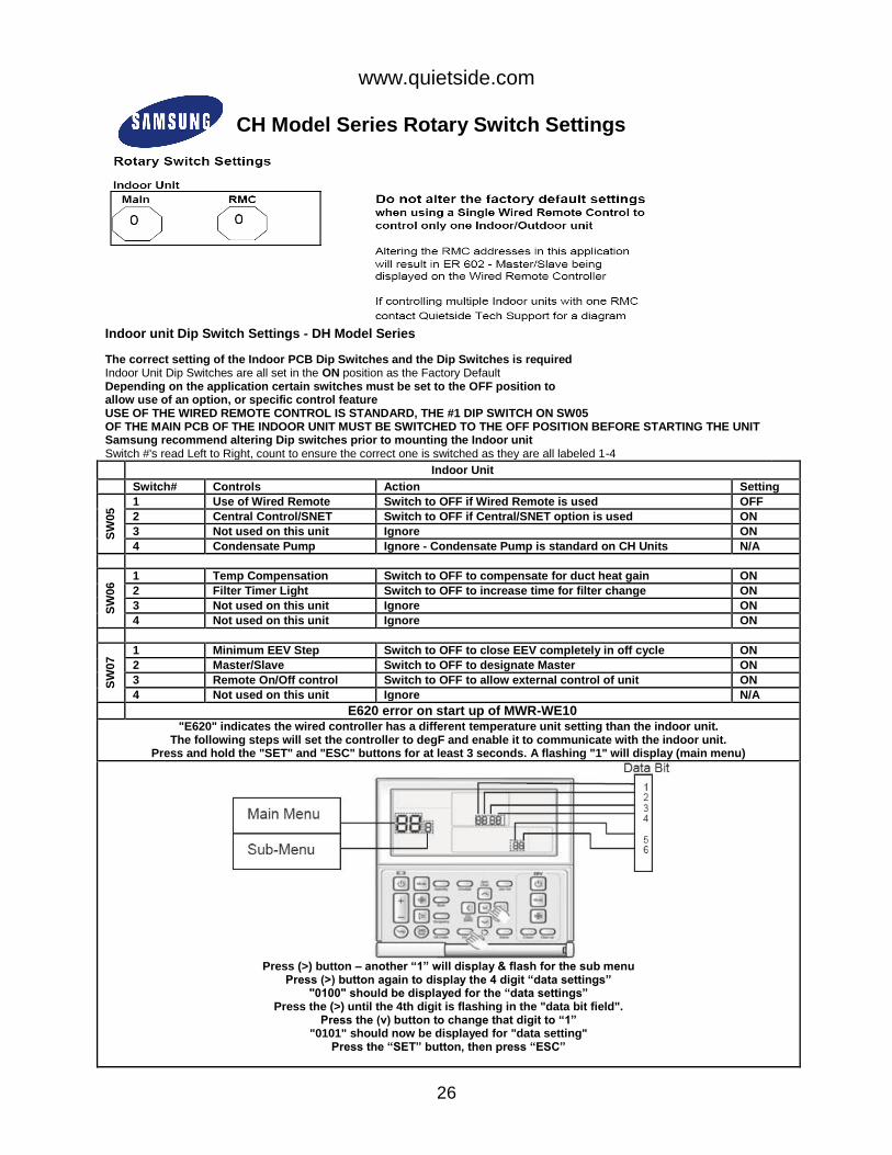
CH Model Series Rotary Switch Settings
Indoor unit Dip Switch Settings - DH Model Series
The correct setting of the Indoor PCB Dip Switches and the Dip Switches is required Indoor Unit Dip Switches are all set in the ON position as the Factory Default Depending on the application certain switches must be set to the OFF position to allow use of an option, or specific control feature USE OF THE WIRED REMOTE CONTROL IS STANDARD, THE #1 DIP SWITCH ON SW05 OF THE MAIN PCB OF THE INDOOR UNIT MUST BE SWITCHED TO THE OFF POSITION BEFORE STARTING THE UNIT Samsung recommend altering Dip switches prior to mounting the Indoor unit Switch #'s read Left to Right, count to ensure the correct one is switched as they are all labeled 1-4
Indoor Unit
Switch# Controls Action Setting
SW
05 1 Use of Wired Remote Switch to OFF if Wired Remote is used OFF
2 Central Control/SNET Switch to OFF if Central/SNET option is used ON
3 Not used on this unit Ignore ON
4 Condensate Pump Ignore - Condensate Pump is standard on CH Units N/A
SW
06 1 Temp Compensation Switch to OFF to compensate for duct heat gain ON
2 Filter Timer Light Switch to OFF to increase time for filter change ON
3 Not used on this unit Ignore ON
4 Not used on this unit Ignore ON
SW
07 1 Minimum EEV Step Switch to OFF to close EEV completely in off cycle ON
2 Master/Slave Switch to OFF to designate Master ON
3 Remote On/Off control Switch to OFF to allow external control of unit ON
4 Not used on this unit Ignore N/A
E620 error on start up of MWR-WE10
"E620" indicates the wired controller has a different temperature unit setting than the indoor unit. The following steps will set the controller to degF and enable it to communicate with the indoor unit.
Press and hold the "SET" and "ESC" buttons for at least 3 seconds. A flashing "1" will display (main menu)
Press (>) button – another “1” will display & flash for the sub menu
Press (>) button again to display the 4 digit “data settings” "0100" should be displayed for the “data settings”
Press the (>) until the 4th digit is flashing in the "data bit field". Press the (v) button to change that digit to “1”
"0101" should now be displayed for "data setting" Press the “SET” button, then press “ESC”

www.quietside.com
27
MH050FXCA2A Dual Zone Heat Pump Outdoor Unit
Matching Indoor units: MH026FNCA, MH026FECA, MH035FNCA, MH035FECA, NJ030MHXCA, NJ035MHXCA, NJ0261HXCA & NJ0351HXCA Power
Power Voltage : 208/230V – 1 Ph – 60 Hz
Control Voltage : DC Fuzzy Logic
Main Breaker Size : 25 A
Line Sizes :
“Liquid” (expanded gas) line 1/4”
Suction 3/8”
ALL LINES MUST BE INSULATED SEPARATELY
Interconnect Length
Maximum Combined Length 100 feet
Maximum / Minimum Individual Length 75 / 10 feet
Vertical lift 49 feet (Trap required at 26ft)
(Note condenser can be above or below evaporator)
Charging
Unit is charged for 65 ft (Factory Charge 70.55oz R410A)
Additional Charge of R410A 0.11oz/ft over 65ft
Charge for Combined Line Run lengths
Length 25 35 45 55 65 75 85 95 100
Added Charge (oz) 0 0 0 0 0 1.1 2.2 3.3 3.9
Interconnecting Wiring
Gauge 14 AWG Power, 1(L), 2(N) & 16 AWG Shielded Communication, F1, F2
Number of Interconnecting Wires 3x14 AWG Power & 2x16 AWG Control = 5 Total

www.quietside.com
28
MH080FXCA4A Quad Zone Heat Pump Outdoor Unit
Matching Indoor units: MH026FNCA, MH026FECA, MH035FNCA, MH035FECA, MH052FNCA, MH052FECA, NJ030MHXCA, NJ035MHXCA, NJ052MHXCA, NJ0261HXCA & NJ0351HXCA Power
Power Voltage : 208/230V – 1 Ph – 60 Hz
Control Voltage : DC Fuzzy Logic
Main Breaker Size : 25 A
Line Sizes :
“Liquid” (expanded gas) line 1/4”
Suction (MH026 & MH035) 3/8” (MH052) 1/2”
ALL LINES MUST BE INSULATED SEPARATELY
Interconnect Length
Maximum Combined Length 225 feet
Maximum / Minimum Individual Length 75 / 10 feet
Vertical lift 98 feet (Trap required at 26ft)
(Note condenser can be above or below evaporator)
Charging
Unit is charged for 131 ft (Factory Charge 98.77oz R410A)
Additional Charge of R410A 0.11oz/ft over 131ft
Charge for Combined Line Run lengths
Length 25 45 65 85 105 131 150 175 200
Added Charge (oz) 0 0 0 0 0 0 2.1 4.8 5.6
Interconnecting Wiring
Gauge 14 AWG Power, 1(L), 2(N) & 16 AWG Shielded Communication, F1, F2
Number of Interconnecting Wires 3x14 AWG Power & 2x16 AWG Control = 5 Total
www.quietside.com
29
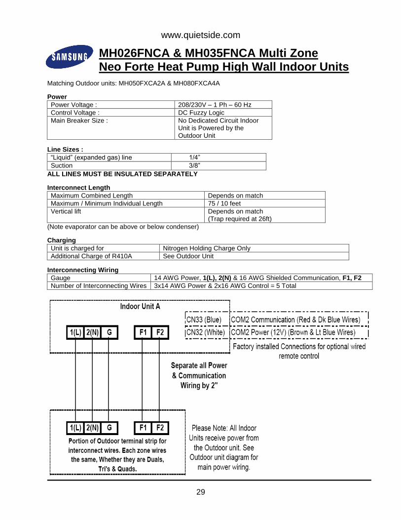
MH026FNCA & MH035FNCA Multi Zone Neo Forte Heat Pump High Wall Indoor Units
Matching Outdoor units: MH050FXCA2A & MH080FXCA4A
Power
Power Voltage : 208/230V – 1 Ph – 60 Hz
Control Voltage : DC Fuzzy Logic
Main Breaker Size : No Dedicated Circuit Indoor Unit is Powered by the Outdoor Unit
Line Sizes :
“Liquid” (expanded gas) line 1/4”
Suction 3/8”
ALL LINES MUST BE INSULATED SEPARATELY
Interconnect Length
Maximum Combined Length Depends on match
Maximum / Minimum Individual Length 75 / 10 feet
Vertical lift Depends on match (Trap required at 26ft)
(Note evaporator can be above or below condenser)
Charging
Unit is charged for Nitrogen Holding Charge Only
Additional Charge of R410A See Outdoor Unit
Interconnecting Wiring
Gauge 14 AWG Power, 1(L), 2(N) & 16 AWG Shielded Communication, F1, F2
Number of Interconnecting Wires 3x14 AWG Power & 2x16 AWG Control = 5 Total
www.quietside.com
30
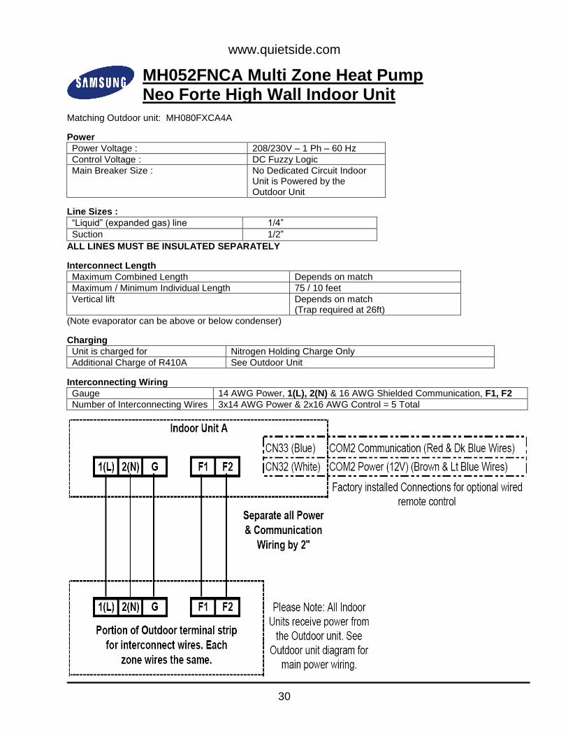
MH052FNCA Multi Zone Heat Pump Neo Forte High Wall Indoor Unit
Matching Outdoor unit: MH080FXCA4A
Power
Power Voltage : 208/230V – 1 Ph – 60 Hz
Control Voltage : DC Fuzzy Logic
Main Breaker Size : No Dedicated Circuit Indoor Unit is Powered by the Outdoor Unit
Line Sizes :
“Liquid” (expanded gas) line 1/4”
Suction 1/2”
ALL LINES MUST BE INSULATED SEPARATELY
Interconnect Length
Maximum Combined Length Depends on match
Maximum / Minimum Individual Length 75 / 10 feet
Vertical lift Depends on match (Trap required at 26ft)
(Note evaporator can be above or below condenser)
Charging
Unit is charged for Nitrogen Holding Charge Only
Additional Charge of R410A See Outdoor Unit
Interconnecting Wiring
Gauge 14 AWG Power, 1(L), 2(N) & 16 AWG Shielded Communication, F1, F2
Number of Interconnecting Wires 3x14 AWG Power & 2x16 AWG Control = 5 Total
www.quietside.com
31
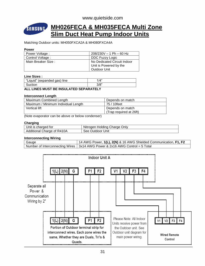
MH026FECA & MH035FECA Multi Zone Slim Duct Heat Pump Indoor Units
Matching Outdoor units: MH050FXCA2A & MH080FXCA4A
Power
Power Voltage : 208/230V – 1 Ph – 60 Hz
Control Voltage : DDC Fuzzy Logic
Main Breaker Size : No Dedicated Circuit Indoor Unit is Powered by the Outdoor Unit
Line Sizes :
“Liquid” (expanded gas) line 1/4”
Suction 3/8”
ALL LINES MUST BE INSULATED SEPARATELY
Interconnect Length
Maximum Combined Length Depends on match
Maximum / Minimum Individual Length 75 / 10feet
Vertical lift Depends on match (Trap required at 26ft)
(Note evaporator can be above or below condenser)
Charging
Unit is charged for Nitrogen Holding Charge Only
Additional Charge of R410A See Outdoor Unit
Interconnecting Wiring
Gauge 14 AWG Power, 1(L), 2(N) & 16 AWG Shielded Communication, F1, F2
Number of Interconnecting Wires 3x14 AWG Power & 2x16 AWG Control = 5 Total

www.quietside.com
32
MH052FECA Multi Multi Zone Slim Duct Heat Pump Indoor Units
Matching Outdoor unit: MH080FXCA4A
Power
Power Voltage : 208/230V – 1 Ph – 60 Hz
Control Voltage : DDC Fuzzy Logic
Main Breaker Size : No Dedicated Circuit Indoor Unit is Powered by the Outdoor Unit
Line Sizes :
“Liquid” (expanded gas) line 1/4”
Suction 1/2”
ALL LINES MUST BE INSULATED SEPARATELY
Interconnect Length
Maximum Combined Length Depends on match
Maximum / Minimum Individual Length 75 /10feet
Vertical lift Depends on match (Trap required at 26ft)
(Note evaporator can be above or below condenser)
Charging
Unit is charged for Nitrogen Holding Charge Only
Additional Charge of R410A See Outdoor Unit
Interconnecting Wiring
Gauge 14 AWG Power, 1(L), 2(N) & 16 AWG Shielded Communication, F1, F2
Number of Interconnecting Wires 3x14 AWG Power & 2x16 AWG Control = 5 Total

www.quietside.com
33
NJ030MHXCA & NJ035MHXCA Multi Zone Mini 4 Way Cassette Heat Pump Indoor Units
Matching Outdoor units: MH050FXCA2A & MH080FXCA4A
Power
Power Voltage : 208/230V – 1 Ph – 60 Hz
Control Voltage : DDC Fuzzy Logic
Main Breaker Size : No Dedicated Circuit Indoor Unit is Powered by the Outdoor Unit
Line Sizes :
“Liquid” (expanded gas) line 1/4”
Suction 3/8”
ALL LINES MUST BE INSULATED SEPARATELY
Interconnect Length
Maximum Combined Length Depends on match
Maximum / Minimum Individual Length 75 / 10 feet
Vertical lift Depends on match (Trap required at 26ft)
(Note evaporator can be above or below condenser)
Charging
Unit is charged for Nitrogen Holding Charge Only
Additional Charge of R410A See Outdoor Unit
Interconnecting Wiring
Gauge 14 AWG Power, 1(L), 2(N) & 16 AWG Shielded Communication, F1, F2
Number of Interconnecting Wires 3x14 AWG Power & 2x16 AWG Control = 5 Total

www.quietside.com
34
NJ052MHXCA Multi Multi Zone Mini 4 Way Cassette Heat Pump Indoor Units
Matching Outdoor unit: MH080FXCA4A
Power
Power Voltage : 208/230V – 1 Ph – 60 Hz
Control Voltage : DDC Fuzzy Logic
Main Breaker Size : No Dedicated Circuit Indoor Unit is Powered by the Outdoor Unit
Line Sizes :
“Liquid” (expanded gas) line 1/4”
Suction 1/2”
ALL LINES MUST BE INSULATED SEPARATELY
Interconnect Length
Maximum Combined Length Depends on match
Maximum / Minimum Individual Length 75 / 10 feet
Vertical lift Depends on match (Trap required at 26ft)
(Note evaporator can be above or below condenser)
Charging
Unit is charged for Nitrogen Holding Charge Only
Additional Charge of R410A See Outdoor Unit
Interconnecting Wiring
Gauge 14 AWG Power, 1(L), 2(N) & 16 AWG Shielded Communication, F1, F2
Number of Interconnecting Wires 3x14 AWG Power & 2x16 AWG Control = 5 Total

www.quietside.com
35
NJ0261HXCA & NJ0351HXCA Multi Zone Mini 1 Way Cassette Heat Pump Indoor Units
Matching Outdoor units: MH050FXCA2A & MH080FXCA4A
Power
Power Voltage : 208/230V – 1 Ph – 60 Hz
Control Voltage : DDC Fuzzy Logic
Main Breaker Size : No Dedicated Circuit Indoor Unit is Powered by the Outdoor Unit
Line Sizes :
“Liquid” (expanded gas) line 1/4”
Suction 3/8”
ALL LINES MUST BE INSULATED SEPARATELY
Interconnect Length
Maximum Combined Length Depends on match
Maximum / Minimum Individual Length 75 / 10 feet
Vertical lift Depends on match (Trap required at 26ft)
(Note evaporator can be above or below condenser)
Charging
Unit is charged for Nitrogen Holding Charge Only
Additional Charge of R410A See Outdoor Unit
Interconnecting Wiring
Gauge 14 AWG Power, 1(L), 2(N) & 16 AWG Shielded Communication, F1, F2
Number of Interconnecting Wires 3x14 AWG Power & 2x16 AWG Control = 5 Total

www.quietside.com
36
*FJM (MH) Model Series Systems Auto Addressing
Step 1 • Rotary switch signifies number of Indoor units connected to Outdoor • Set the rotary switch to the number of units, either 2, 3 or 4
Step 2 • Auto Addressing • Indoor units rotary switches do not need to be altered • Leave all Dip switches on the Outdoor unit to the factory settings • Turn on the unit, it will start a count to check communications with all Indoor units • LH display will count 00 to 15 • Once Indoor units are tracked it will scroll 00 as it finds the Indoors • Unit will now display E199 asking for a pipe check • MWR-WH00 will display E599 • Press K1 switch once • This starts the auto addressing mode • Display will show |-5 • Compressor will start and the unit will open each EEV in turn to check that the correct indoor unit is
connected to the correct EEV • Unit will display on other LED the results scrolling 00, 01, 02, 03 as it establish communication
Step 3 • Once completed it will display an OK signal, now the unit can be run in test mode, either Cooling or
Heating • Press K2 Button ONCE for Heating Trial mode : Display will show |-1 • Press K2 Button TWICE to add refrigerant : Display will now show |-2 • Press K2 Button THREE times for Cooling trial mode : Display will now show |-3 • Press K2 Button FOUR times for Pump Down mode : Display will now show |-4 •
* Please note: the Auto Addressing Procedure cannot be used on Slim Duct air handlers, Neo Forte High Wall
indoor units that have been installed with the optional MWR-WH00 wired remote or that are piped in nonconsecutive order from the top set of valves down on the outdoor unit. These scenarios require the use of the Manual Addressing procedure.

www.quietside.com
37
*FJM (MH) Model Series Systems Manual Addressing
Step 1
• Manual addressing is used when a BMS system is used or Ducted and Wall Mount units have Wired Remote controls
• Set the rotary switch to the number of units, either 2, 3 or 4 Step 2
• Manual Addressing • *Set Dip Switch #1 on Outdoor unit to OFF
Step 3 • On Indoor units set SW02 the MAIN address to the following based on which set of refrigerant
connections the unit is piped to • Unit piped to the top set of connections = 0 • Unit piped to the second set of connections from top = 1 • Unit piped to the third set of connections from top = 2 • Unit Piped to the lowest set of connections = 3 • System can now be powered up
Step 4 • On initial power up LH display will scroll 00 Through 15 • Once Indoor units are tracked LH display will show 00, 01, 02 and 03 depending how many Indoor
units are installed Step 5
• Use the K2 Button to put the unit into either Cooling or Heating trial mode • Press K2 Button ONCE for Heating Trial mode : Display will show |-1 • Press K2 Button TWICE to add refrigerant : Display will now show |-2 • Press K2 Button THREE times for Cooling trial mode : Display will now show |-3 • Press K2 Button FOUR times for Pump Down mode : Display will now show |-4
* Dip Switch #1 should be in the OFF position (MANDATORY on the FECA Ducted unit)
1-Way Cassette
Mini 4-Way Cassette

www.quietside.com
38
Basic Installation Tips
Sizing Computer/Data Rooms : Basic sizing is 200-250 sqft per 12,000 Btu/h Commercial/Retail : Basic sizing is 400-450 sqft per 12,000 Btu/h Residential : Basic sizing is 550-600 sqft per 12,000 Btu/h Low Ambient Cooling Computer/Data Rooms and Commercial: As standard these units have low ambient cooling capability down to 14 DegF outdoor temperature. THESE UNITS CANNOT OPERATE IN COOLING BELOW 14 DEG F AMBIENT TEMPERATURE, UNLESS EQUIPPED WITH AN APPROVED WIND BAFFLE TO PROTECT THE OUTDOOR UNIT, IN WHICH CASE PERFORMANCE CAN BE EXPECTED DOWN TO 0 DEG F OUTDOOR TEMPERATURE. ALTHOUGH IF A PROLONGED OFF CYCLE IS EXPERIENCED, THE UNIT MAY NOT RESTART. R410A Refrigerant Higher pressures (close to double) than R22, but the operating temperatures are very similar to those with R22, for example R410A A saturated suction temp of 45 DegF = Suction Pressure of 130 Psig R22 A saturated suction temp of 45 DegF = Suction Pressure of 76 Psig R410A uses a POE oil compared to the mineral oil used with R22, the POE oil is attractive to water so it is very important to : Minimize the time that the system is open to the atmosphere Ensure that a deep vacuum is pulled on the system, 200 microns or less Do not install any sight glasses or filter driers in the line set.
Note: It is not necessary to remove refrigerant for line sets shorter than the specified length of the factory charge.

www.quietside.com
39
R410A Refrigerant (continued) The gauge connection on the Samsung units is a 5/16” male, so an adaptor, part # R410A-ADPT (Yellow Jacket item #19173) is required to connect a standard North American set of R410A gauges to the Samsung unit. Unit location Indoor unit : High Wall units should be located a minimum of 4ft from the ground. Also, some of the Indoor unit clearances listed in the specific unit Installation Manuals can be decrease to a minimum clearance of 2 inches from the ceiling to the top of the unit, while still maintaining unit performance and efficiency levels. Ensure that no obstacles are directly in front of the unit for a Minimum Distance of 10-12ft on the AQV/N/AR09 & 12, MH026/035FNCA, 20-25ft on the AQV/N/AR18 & 24, MH052FNCA and 25-30ft on the AQV/N36 so that bounce back of the conditioned air is prevented and adequate airflow is maintained, keeping the indoor coil warm and allowing the system to run to full capacity when necessary. If any system is prevented from running at full capacity regularly, whether it is from impeded airflow or over sizing, it will have an adverse affect on the system ability to properly return oil to the compressor. Over time this will cause inconsistent performance, error codes, and premature failure of components. Ceiling Cassette units must have a Minimum Distance of 5ft from the louver opening to any wall or other obstacle for the same reasons as listed above. Outdoor unit : Ensure line set runs are adhered to, it is required that a minimum line set length of 10ft maintained and exceeding the published maximum line set length is not permitted, under any circumstance. Also, keep in mind that, since the expansion valve is located in the outdoor unit, the line set is merely an extension of the indoor coil and, although insulated, the longer the line set run is the more likely there will noticeable loss of capacity. Minimum clearances of 6” behind and 24” in front of the outdoor unit must also be maintained, enough clearance must be maintained from the sides to accommodate service of the unit. Since these units are heat pumps, Raise up Outdoor unit 4 to 6” from the pad/ground to help drain the unit after a defrost cycle. Also, ensure unit is capable of operating in desired ambient temperatures. As previously stated, if the outdoor coil temperature is allowed to drop below 14 DegF, the system will lock out, not restarting until that temperature rises above 14 DegF.

www.quietside.com