
Basic Low Level Concepts s Router micro-architectures...
12
1 © Sudhakar Yalamanchili, Georgia Institute of Technology (except as indicated) Basic Low Level Concepts ECE 8813a (2) Course Outline • Operation of a single link: switching and flow control • Operation through a single switch: Router micro-architectures Buffering, arbitration, scheduling, datapath • Operation through multiple switches: Topologies & Routing Direct, indirect, regular, irregular • Formal models and analysis for deadlock and livelock freedom Optimization : technology, congestion, reliability Case Studies ECE 8813a (3) Overview • Main architectural issues for communication over a single link Message units Flow control (lossless links) Switching (next) Buffer management (later) Arbitration & Scheduling (later) • System Goals : high levels of link utilization and minimal impact on end-to-end latency ECE 8813a (4) Sources • Chapters 1 & 2 “Interconnection Networks: An Engineering Approach”, J. Duato, S. Yalamanchili and L. Ni, Morgan Kaufmann (pubs.) • Papers Virtual Channel Flow Control Optimistic Flow Control – Illinois Fast Messages
Transcript of Basic Low Level Concepts s Router micro-architectures...
1
© Sudhakar Yalamanchili, Georgia Institute of Technology (except as indicated)
Basic Low Level Concepts
ECE 8813a (2)
Course Outline
• Operation of a single link: switching and flow control
• Operation through a single switch: Router micro-architectures v Buffering, arbitration, scheduling,
datapath
• Operation through multiple switches: Topologies & Routing v Direct, indirect, regular, irregular
• Formal models and analysis for deadlock and livelock freedom
Op
timization
: technology, congestion, reliability
Cas
e S
tud
ies
ECE 8813a (3)
Overview
• Main architectural issues for communication over a single link v Message units v Flow control (lossless links) v Switching (next) v Buffer management (later) v Arbitration & Scheduling (later)
• System Goals: high levels of link utilization and minimal impact on end-to-end latency
ECE 8813a (4)
Sources
• Chapters 1 & 2 v “Interconnection Networks: An Engineering
Approach”, J. Duato, S. Yalamanchili and L. Ni, Morgan Kaufmann (pubs.)
• Papers v Virtual Channel Flow Control v Optimistic Flow Control – Illinois Fast Messages
2
ECE 8813a (5)
pro
c/m
em b
us
IO b
us
or
pro
c/m
em b
us
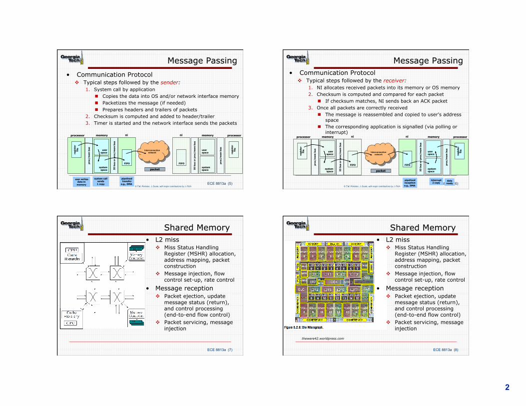
Message Passing • Communication Protocol
v Typical steps followed by the sender: 1. System call by application
n Copies the data into OS and/or network interface memory n Packetizes the message (if needed) n Prepares headers and trailers of packets
2. Checksum is computed and added to header/trailer 3. Timer is started and the network interface sends the packets
processor memory
user space
system space
reg
iste
r fi
le
ni
FIFO
Interconnection network
ni
FIFO
memory
user space
system space
processor
reg
iste
r fi
le
packet
user writes data in
memory
system call sends 1 copy
pipelined transfer
e.g., DMA
IO b
us
or
pro
c/m
em b
us
pro
c/m
em b
us
© T.M. Pinkston, J. Duato, with major contributions by J. Filch ECE 8813a (6)
Message Passing • Communication Protocol
v Typical steps followed by the receiver: 1. NI allocates received packets into its memory or OS memory 2. Checksum is computed and compared for each packet
n If checksum matches, NI sends back an ACK packet 3. Once all packets are correctly received
n The message is reassembled and copied to user's address space
n The corresponding application is signalled (via polling or interrupt)
pro
c/m
em b
us
IO b
us
or
pro
c/m
em b
us
processor memory
user space
system space
reg
iste
r fi
le
ni
FIFO
Interconnection network
ni
FIFO
memory
user space
system space
processor
reg
iste
r fi
le
packet
data ready
interrupt 2 copy
pipelined reception e.g., DMA
IO b
us
or
pro
c/m
em b
us
pro
c/m
em b
us
© T.M. Pinkston, J. Duato, with major contributions by J. Filch
ECE 8813a (7)
Shared Memory
• L2 miss v Miss Status Handling
Register (MSHR) allocation, address mapping, packet construction
v Message injection, flow control set-up, rate control
• Message reception v Packet ejection, update
message status (return), and control processing (end-to-end flow control)
v Packet servicing, message injection
ECE 8813a (8)
Shared Memory
thewere42.worldpress.com
• L2 miss v Miss Status Handling
Register (MSHR) allocation, address mapping, packet construction
v Message injection, flow control set-up, rate control
• Message reception v Packet ejection, update
message status (return), and control processing (end-to-end flow control)
v Packet servicing, message injection
3
ECE 8813a (9)
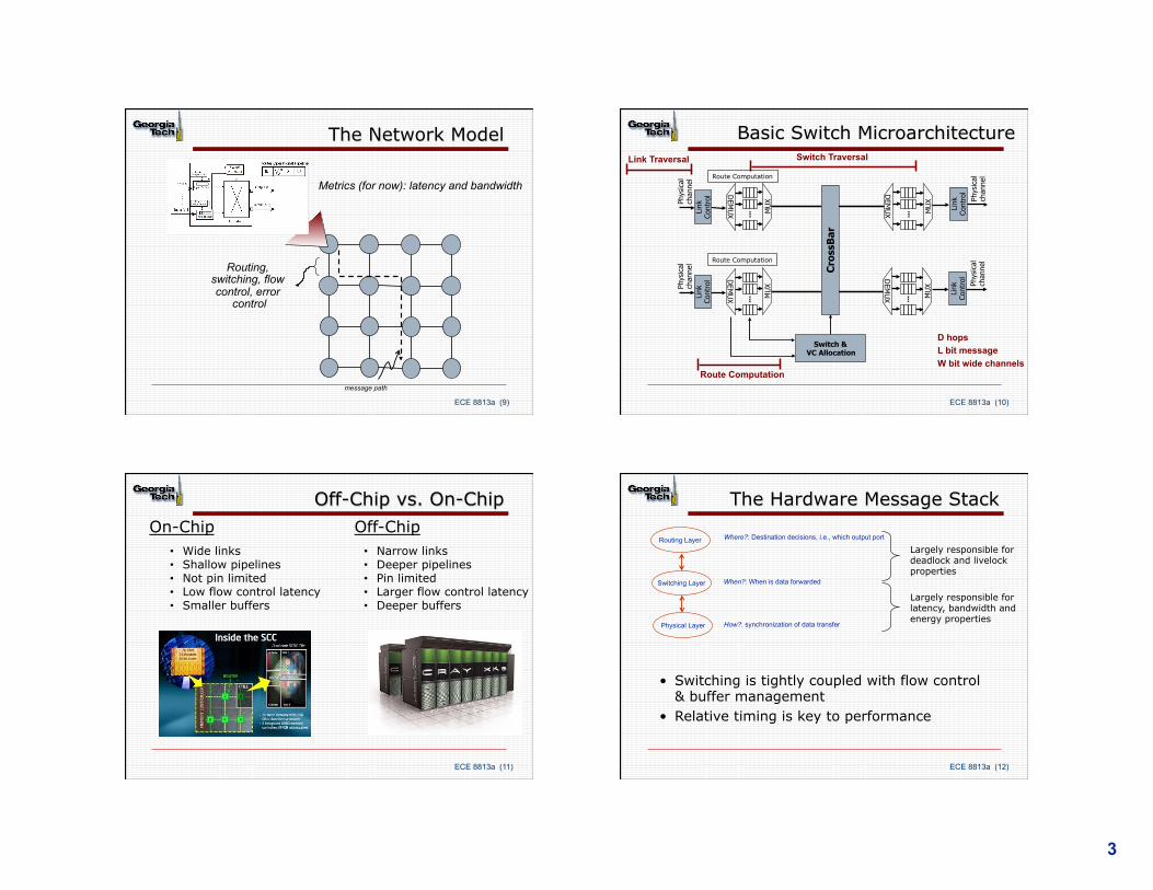
The Network Model
message path
Metrics (for now): latency and bandwidth
Routing, switching, flow control, error
control
ECE 8813a (10)
Basic Switch Microarchitecture Switch Traversal
Route Computation
Link Traversal
D hops L bit message W bit wide channels
Phys
ical
ch
anne
l Ph
ysic
al
chan
nel
Link
Co
ntro
l
... M
UX
DEM
UX
Link
Co
ntro
l
... M
UX
DEM
UX
DEM
UX
Link
Co
ntro
l
Phys
ical
ch
anne
l
... M
UX
DEM
UX
Link
Co
ntro
l
Phys
ical
ch
anne
l
... M
UX
Cro
ssB
ar
Switch & VC Allocation
Route Computation
Route Computation
ECE 8813a (11)
Off-Chip vs. On-Chip
• Wide links • Shallow pipelines • Not pin limited • Low flow control latency • Smaller buffers
• Narrow links • Deeper pipelines • Pin limited • Larger flow control latency • Deeper buffers
On-Chip Off-Chip
ECE 8813a (12)
The Hardware Message Stack
Routing Layer
Switching Layer
Physical Layer
Where?: Destination decisions, i.e., which output port
When?: When is data forwarded
How?: synchronization of data transfer
• Switching is tightly coupled with flow control & buffer management
• Relative timing is key to performance
Largely responsible for deadlock and livelock properties
Largely responsible for latency, bandwidth and energy properties
4
ECE 8813a (13)
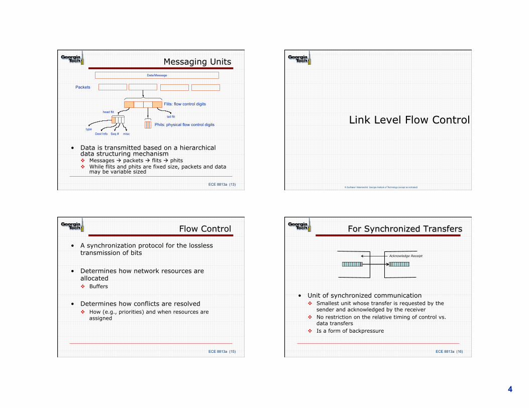
Messaging Units
• Data is transmitted based on a hierarchical data structuring mechanism v Messages à packets à flits à phits v While flits and phits are fixed size, packets and data
may be variable sized
Data/Message
head flit
Flits: flow control digits
Phits: physical flow control digits
Packets
Dest Info Seq # misc
tail flit
type
© Sudhakar Yalamanchili, Georgia Institute of Technology (except as indicated)
Link Level Flow Control
ECE 8813a (15)
Flow Control
• A synchronization protocol for the lossless transmission of bits
• Determines how network resources are allocated v Buffers
• Determines how conflicts are resolved v How (e.g., priorities) and when resources are
assigned
ECE 8813a (16)
For Synchronized Transfers
• Unit of synchronized communication v Smallest unit whose transfer is requested by the
sender and acknowledged by the receiver v No restriction on the relative timing of control vs.
data transfers v Is a form of backpressure
Acknowledge Receipt
5
ECE 8813a (17)
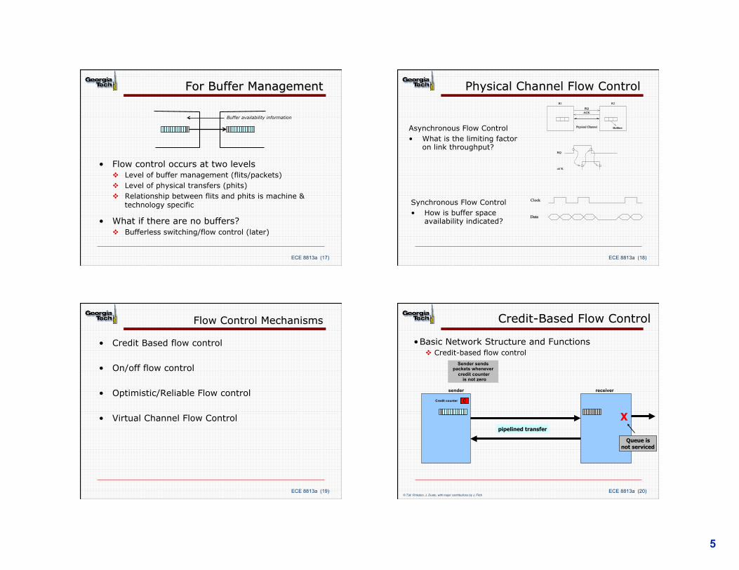
For Buffer Management
• Flow control occurs at two levels v Level of buffer management (flits/packets) v Level of physical transfers (phits) v Relationship between flits and phits is machine &
technology specific
• What if there are no buffers? v Bufferless switching/flow control (later)
Buffer availability information
ECE 8813a (18)
Physical Channel Flow Control
Synchronous Flow Control • How is buffer space
availability indicated?
Asynchronous Flow Control • What is the limiting factor
on link throughput?
ECE 8813a (19)
Flow Control Mechanisms
• Credit Based flow control
• On/off flow control
• Optimistic/Reliable Flow control
• Virtual Channel Flow Control
ECE 8813a (20)
Credit-Based Flow Control
• Basic Network Structure and Functions v Credit-based flow control
receiver sender
Sender sends packets whenever
credit counter is not zero
10 Credit counter 9 8 7 6 5 4 3 2 1 0
X
Queue is not serviced
pipelined transfer
© T.M. Pinkston, J. Duato, with major contributions by J. Filch
6
ECE 8813a (21)
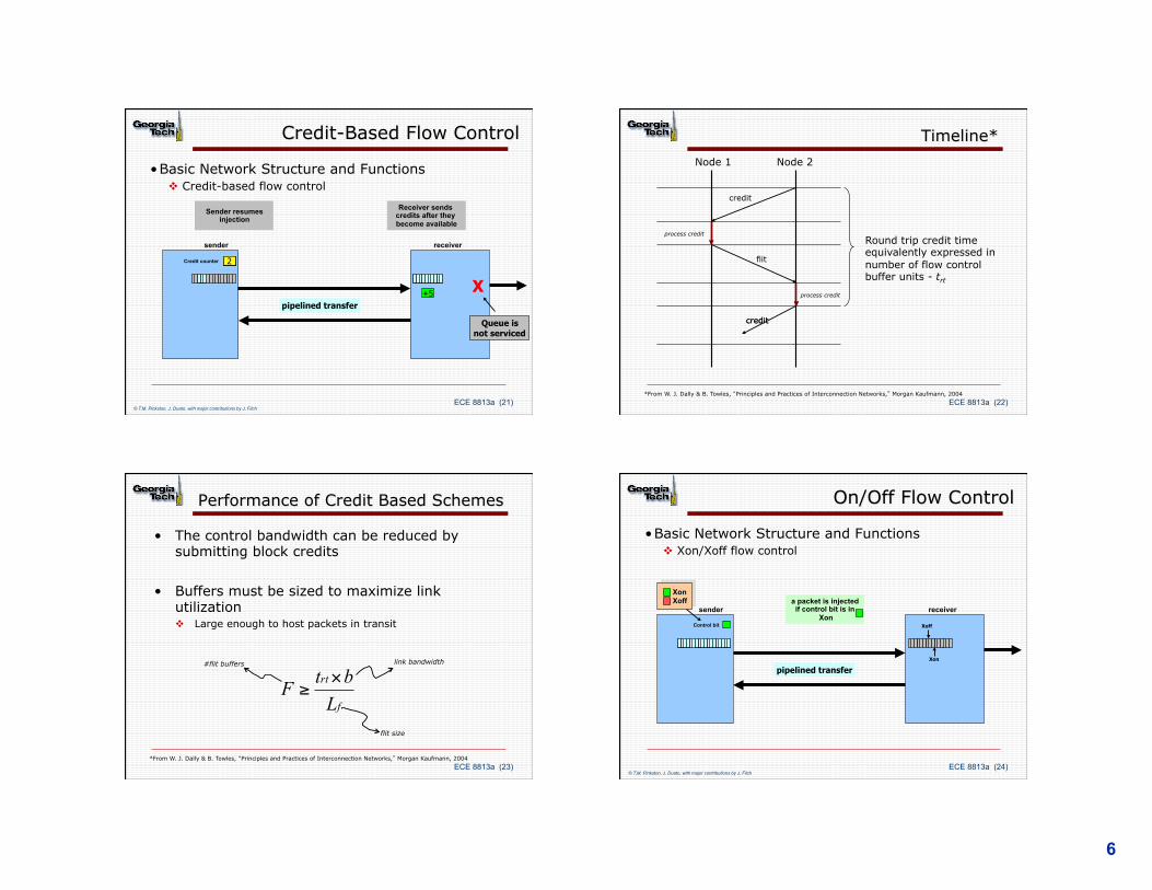
Credit-Based Flow Control
• Basic Network Structure and Functions v Credit-based flow control
receiver sender
10 Credit counter 9 8 7 6 5 4 3 2 1 0
+5
5 4 3 2
X
Queue is not serviced
Receiver sends credits after they become available
Sender resumes injection
pipelined transfer
© T.M. Pinkston, J. Duato, with major contributions by J. Filch ECE 8813a (22)
Timeline*
credit
flit
credit
credit
Node 1 Node 2
process credit
process credit
Round trip credit time equivalently expressed in number of flow control buffer units - trt
*From W. J. Dally & B. Towles, “Principles and Practices of Interconnection Networks,” Morgan Kaufmann, 2004
ECE 8813a (23)
Performance of Credit Based Schemes
• The control bandwidth can be reduced by submitting block credits
• Buffers must be sized to maximize link utilization v Large enough to host packets in transit
f
rt
LbtF ×
≥
*From W. J. Dally & B. Towles, “Principles and Practices of Interconnection Networks,” Morgan Kaufmann, 2004
link bandwidth
flit size
#flit buffers
ECE 8813a (24)
On/Off Flow Control
• Basic Network Structure and Functions v Xon/Xoff flow control
receiver sender
Xon Xoff a packet is injected
if control bit is in Xon
Control bit
Xon
Xoff
pipelined transfer
© T.M. Pinkston, J. Duato, with major contributions by J. Filch

7
ECE 8813a (25)
On-Off Flow Control
• Basic Network Structure and Functions v Xon/Xoff flow control
receiver sender
Xon Xoff
When Xoff threshold is
reached, an Xoff notification is sent
Control bit Xoff
Xon
When in Xoff, sender cannot inject packets
X
Queue is not serviced
pipelined transfer
© T.M. Pinkston, J. Duato, with major contributions by J. Filch ECE 8813a (26)
On-Off Flow Control
• Basic Network Structure and Functions v Xon/Xoff flow control
receiver sender
Xon Xoff
When Xon threshold is
reached, an Xon notification is sent
Control bit
Xon
Xoff
X
Queue is not serviced
pipelined transfer
© T.M. Pinkston, J. Duato, with major contributions by J. Filch
ECE 8813a (27)
Timeline*
flit
off
Node 1 Node 2
process FC
*From W. J. Dally & B. Towles, “Principles and Practices of Interconnection Networks,” Morgan Kaufmann, 2004
flit
flit
flit
flit
flit
flit
flit
on
Hit the high water mark (stop)
Hit the low water mark (go)
Go
Stop
ECE 8813a (28)
Performance of On-Off Schemes
• Buffer sizing and position of Stop and Go watermarks
• To operate at full speed buffer size must be at least 2F
Go
Stop
f
rt
LbtF ×
≥
*From W. J. Dally & B. Towles, “Principles and Practices of Interconnection Networks,” Morgan Kaufmann, 2004
8
ECE 8813a (29)
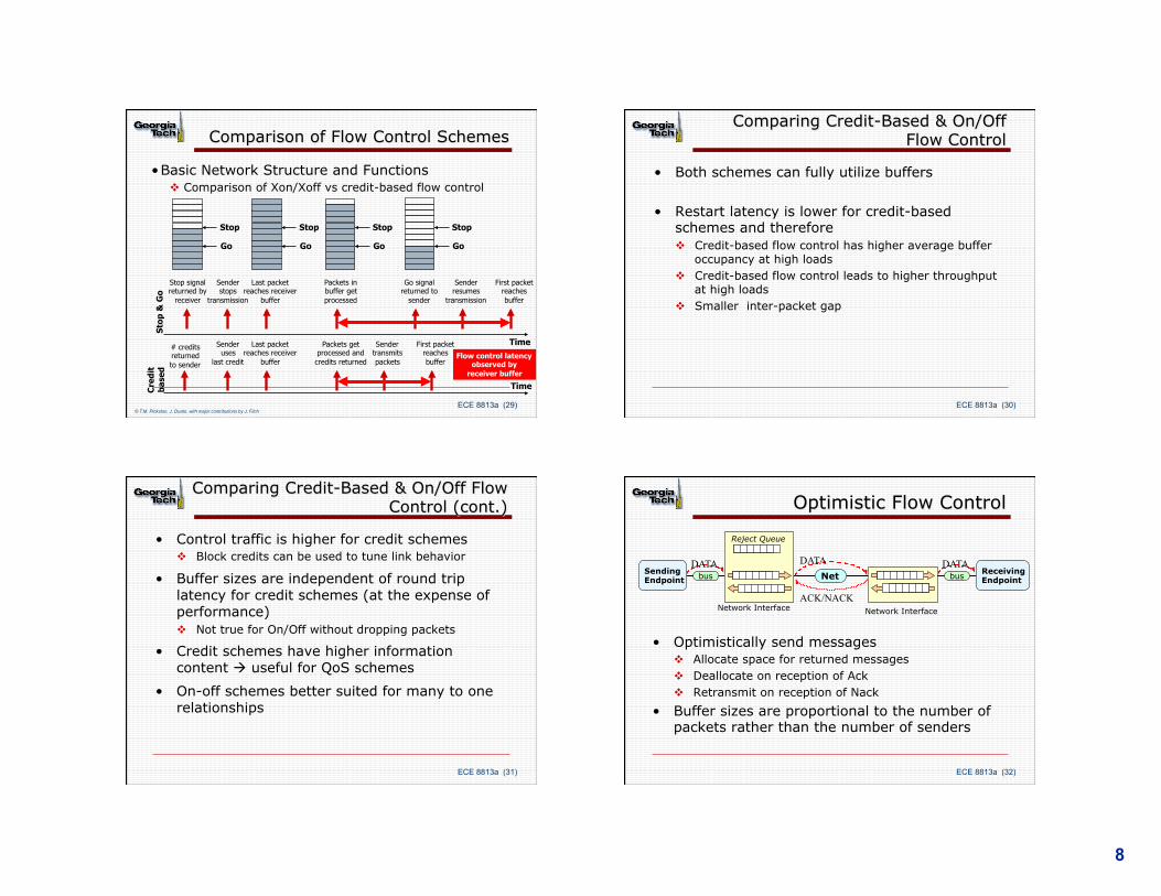
Comparison of Flow Control Schemes
• Basic Network Structure and Functions v Comparison of Xon/Xoff vs credit-based flow control
Sto
p &
Go
Time
Cre
dit
b
ased
Time
Go
Stop
Go
Stop
Go
Stop
Sender stops
transmission
Last packet reaches receiver
buffer
Stop
Go
Packets in buffer get processed
Go signal returned to
sender
Sender resumes
transmission
First packet reaches buffer
# credits returned to sender
Sender uses
last credit
Last packet reaches receiver
buffer
Packets get processed and credits returned
Sender transmits packets
First packet reaches buffer
Flow control latency observed by
receiver buffer
Stop signal returned by
receiver
© T.M. Pinkston, J. Duato, with major contributions by J. Filch ECE 8813a (30)
Comparing Credit-Based & On/Off Flow Control
• Both schemes can fully utilize buffers
• Restart latency is lower for credit-based schemes and therefore v Credit-based flow control has higher average buffer
occupancy at high loads v Credit-based flow control leads to higher throughput
at high loads v Smaller inter-packet gap
ECE 8813a (31)
Comparing Credit-Based & On/Off Flow Control (cont.)
• Control traffic is higher for credit schemes v Block credits can be used to tune link behavior
• Buffer sizes are independent of round trip latency for credit schemes (at the expense of performance) v Not true for On/Off without dropping packets
• Credit schemes have higher information content à useful for QoS schemes
• On-off schemes better suited for many to one relationships
ECE 8813a (32)
Optimistic Flow Control
• Optimistically send messages v Allocate space for returned messages v Deallocate on reception of Ack v Retransmit on reception of Nack
• Buffer sizes are proportional to the number of packets rather than the number of senders
Receiving Endpoint
Sending Endpoint
DATA DATA
ACK/NACK
bus Net
Network Interface
DATA bus
Network Interface
Reject Queue
9
ECE 8813a (33)
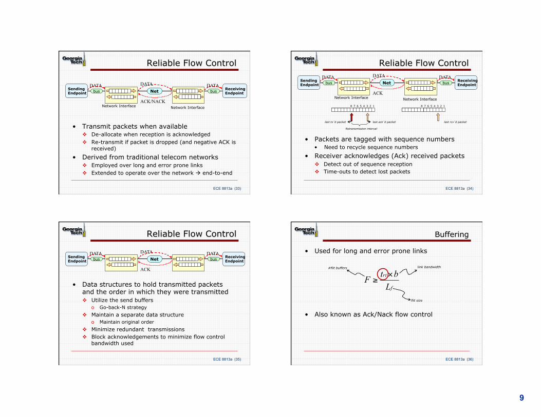
Reliable Flow Control
• Transmit packets when available v De-allocate when reception is acknowledged v Re-transmit if packet is dropped (and negative ACK is
received) • Derived from traditional telecom networks
v Employed over long and error prone links v Extended to operate over the network à end-to-end
Receiving Endpoint
Sending Endpoint
DATA DATA
ACK/NACK
bus Net
Network Interface
DATA bus
Network Interface
ECE 8813a (34)
Reliable Flow Control
Receiving Endpoint
Sending Endpoint
DATA DATA
ACK
bus Net
Network Interface
DATA bus
Network Interface
1 2 3 4 5 6 7 8 1 2 3 4 5 6 7 8
last ack’d packet last tx’d packet
• Packets are tagged with sequence numbers • Need to recycle sequence numbers
• Receiver acknowledges (Ack) received packets v Detect out of sequence reception v Time-outs to detect lost packets
last rcv’d packet
Retransmission interval
ECE 8813a (35)
Reliable Flow Control
• Data structures to hold transmitted packets and the order in which they were transmitted v Utilize the send buffers
o Go-back-N strategy v Maintain a separate data structure
o Maintain original order v Minimize redundant transmissions v Block acknowledgements to minimize flow control
bandwidth used
Receiving Endpoint
Sending Endpoint
DATA DATA
ACK
bus Net DATA
bus
ECE 8813a (36)
Buffering
• Used for long and error prone links
• Also known as Ack/Nack flow control
f
rt
LbtF ×
≥
link bandwidth
flit size
#flit buffers
10
ECE 8813a (37)
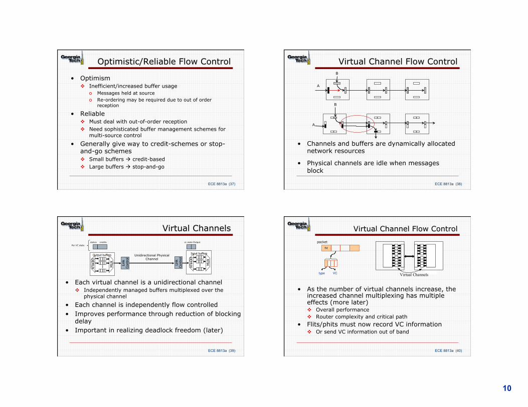
Optimistic/Reliable Flow Control
• Optimism v Inefficient/increased buffer usage
o Messages held at source o Re-ordering may be required due to out of order
reception
• Reliable v Must deal with out-of-order reception v Need sophisticated buffer management schemes for
multi-source control • Generally give way to credit-schemes or stop-
and-go schemes v Small buffers à credit-based v Large buffers à stop-and-go
ECE 8813a (38)
Virtual Channel Flow Control
A
B
A
B
• Channels and buffers are dynamically allocated network resources
• Physical channels are idle when messages block
ECE 8813a (39)
Virtual Channels
• Each virtual channel is a unidirectional channel v Independently managed buffers multiplexed over the
physical channel • Each channel is independently flow controlled • Improves performance through reduction of blocking
delay • Important in realizing deadlock freedom (later)
Input buffers
Link
Co
ntro
l
... MU
X
DEM
UX
Output buffers
DEM
UX
Link
Co
ntro
l
... MU
X
Output status credits vc state Per VC state
Unidirectional Physical Channel
ECE 8813a (40)
Virtual Channel Flow Control
• As the number of virtual channels increase, the increased channel multiplexing has multiple effects (more later) v Overall performance v Router complexity and critical path
• Flits/phits must now record VC information v Or send VC information out of band
Virtual ChannelsVC
flit
type
packet

11
ECE 8813a (41)
Tile R
Tile R
Tile R
Tile R
Tile R
Tile R
Tile R
Tile R
Tile R
Tile R
Tile R
Tile R
Tile R
Tile R
Tile R
Tile R
Tile R
Tile R
Tile R
Tile R
Tile R
Tile R
Tile R
Tile R
V1
V2
n 24 dual core tiles n 8 voltage and 28 frequency islands n X-Y routed mesh: 144 bit physical channels
Mem
ory
Con
trol
ler
Mem
ory
Con
trol
ler
Mem
ory
Con
trol
ler
Mem
ory
Con
trol
ler
Intel Single Chip Cloud Computer (SCC)
ECE 8813a (42)
Intel SCC Message Format
J. Howard et. Al, “A 48-Core IA-32 Processor in 45 nm CMOS Using On-Die Message-Passing and DVFS for Performance and Power Scaling.” IEEE Journal of Solid-State Circuits, vol. 46, no. 1, January 2011.
Flit Types: Null Credit Body/tail control
ECE 8813a (43)
Flow Control: Global View
• Flow control parameters are tuned based on link length, link width and processing overhead at the end-points
• Effective FC and buffer management is necessary for high link utilizations à network throughput v In-band vs. out of band flow control
• Links maybe non-uniform, e.g., lengths/widths on chips v Buffer sizing for long links
ECE 8813a (44)
Flow Control: Global View
• Latency: overlapping FC, buffer management and switching à impacts end-to-end latency
• In-band vs. out-of band flow control v Use link bandwidth vs. additional side-band signals
12
ECE 8813a (45)
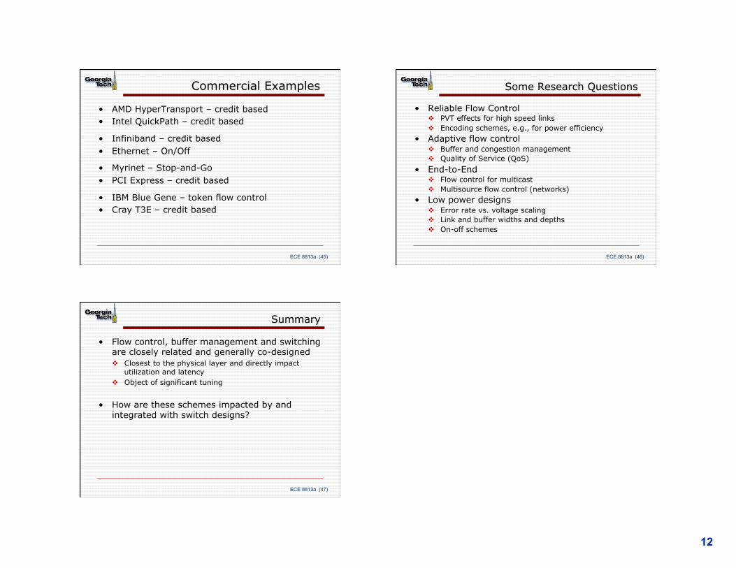
Commercial Examples
• AMD HyperTransport – credit based • Intel QuickPath – credit based
• Infiniband – credit based • Ethernet – On/Off
• Myrinet – Stop-and-Go • PCI Express – credit based
• IBM Blue Gene – token flow control • Cray T3E – credit based
ECE 8813a (46)
Some Research Questions
• Reliable Flow Control v PVT effects for high speed links v Encoding schemes, e.g., for power efficiency
• Adaptive flow control v Buffer and congestion management v Quality of Service (QoS)
• End-to-End v Flow control for multicast v Multisource flow control (networks)
• Low power designs v Error rate vs. voltage scaling v Link and buffer widths and depths v On-off schemes
ECE 8813a (47)
Summary
• Flow control, buffer management and switching are closely related and generally co-designed v Closest to the physical layer and directly impact
utilization and latency v Object of significant tuning
• How are these schemes impacted by and integrated with switch designs?