BASIC HYDRONIC SYSTEM DESIGN - ctashrae.org · 3 EXPANSION TANKS Control pressure, control problems...
25
1 Hydronic Systems B-1 P-B-1 B-2 P-B-2 AS-1 ET-1 P-1 P-2 FCU FCU FCU FCU FCU FCU BASIC HYDRONIC SYSTEM DESIGN Generation Equipment Boilers, Chillers, Cooling Towers, WWHPs, etc. Terminal Units Fan Coils, Chilled Beams, Finned Tube, Radiant, etc. Decoupler Closely Spaced Tees Primary Pumps P-1 & P-2 Distribution Piping Air / Dirt Separator Expansion Tank Secondary Pumps P-B-1 & P-B-2
Transcript of BASIC HYDRONIC SYSTEM DESIGN - ctashrae.org · 3 EXPANSION TANKS Control pressure, control problems...
1
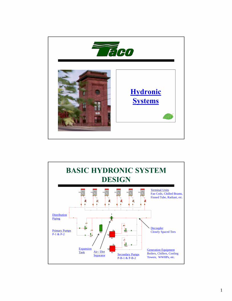
Hydronic Systems
B-1
P-B-1
B-2
P-B-2
AS-1
ET-1
P-1
P-2
FCU FCU FCU FCU FCU FCU
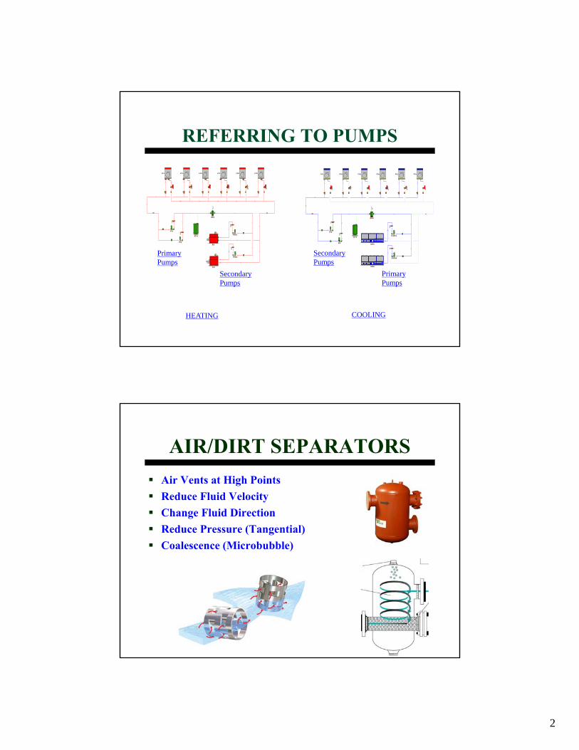
BASIC HYDRONIC SYSTEM DESIGN
Generation EquipmentBoilers, Chillers, Cooling Towers, WWHPs, etc.
Terminal UnitsFan Coils, Chilled Beams, Finned Tube, Radiant, etc.
DecouplerClosely Spaced TeesPrimary Pumps
P-1 & P-2
DistributionPiping
Air / DirtSeparator
ExpansionTank
Secondary PumpsP-B-1 & P-B-2
2
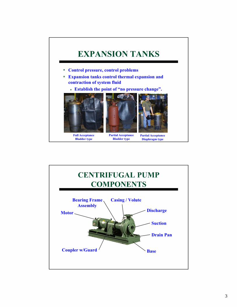
REFERRING TO PUMPS
HEATING
P-CH-1
P-CH-2
AS-2
ET-2
P-3
P-4
FCU FCU FCU FCU FCU FCU
CH-1
CH-2
B-1
P-B-1
B-2
P-B-2
AS-1
ET-1
P-1
P-2
FCU FCU FCU FCU FCU FCU
COOLING
PrimaryPumps
SecondaryPumps
SecondaryPumps
PrimaryPumps
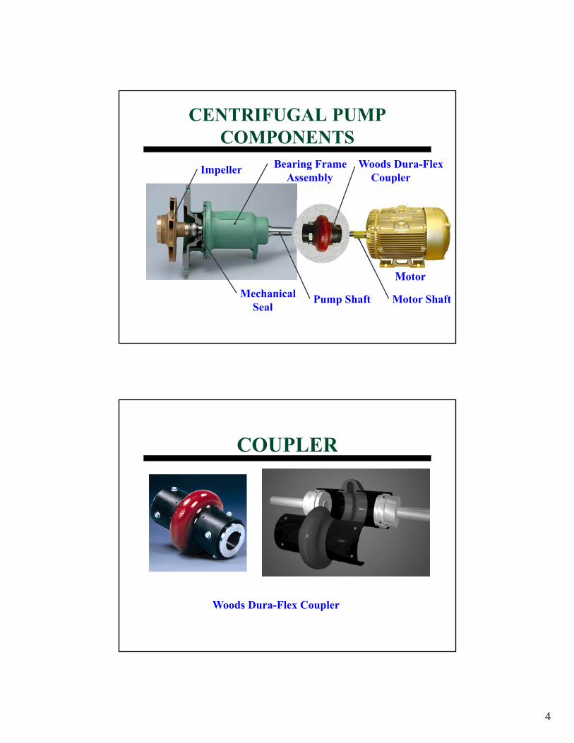
AIR/DIRT SEPARATORSAir Vents at High PointsReduce Fluid VelocityChange Fluid DirectionReduce Pressure (Tangential)Coalescence (Microbubble)
3
EXPANSION TANKS
Control pressure, control problemsExpansion tanks control thermal expansion and contraction of system fluid
Establish the point of “no pressure change”.
Full Acceptance Bladder type
Partial Acceptance Bladder type
Partial Acceptance Diaphragm type
Casing / Volute
CENTRIFUGAL PUMP COMPONENTS
Drain Pan
Suction
Discharge
Base
Motor
Bearing Frame Assembly
Coupler w/Guard
4
CENTRIFUGAL PUMP COMPONENTS
Pump ShaftMechanical Seal
Bearing Frame Assembly
Impeller Woods Dura-Flex Coupler
Motor Shaft
Motor
COUPLER
Woods Dura-Flex Coupler
5
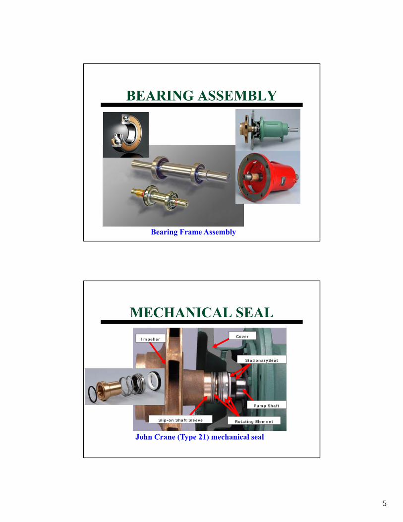
BEARING ASSEMBLY
Bearing Frame Assembly
MECHANICAL SEAL
John Crane (Type 21) mechanical seal
Cover
Rotating Element
Pump Shaft
Slip-on Shaft Sleeve
Impeller
StationarySeat
6
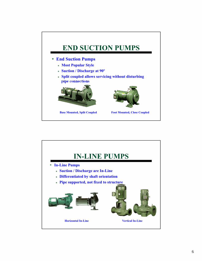
END SUCTION PUMPSEnd Suction Pumps
Most Popular StyleSuction / Discharge at 90ºSplit coupled allows servicing without disturbing pipe connections
Base Mounted, Split Coupled Foot Mounted, Close Coupled
IN-LINE PUMPSIn-Line Pumps
Suction / Discharge are In-LineDifferentiated by shaft orientationPipe supported, not fixed to structure
Horizontal In-Line Vertical In-Line
7
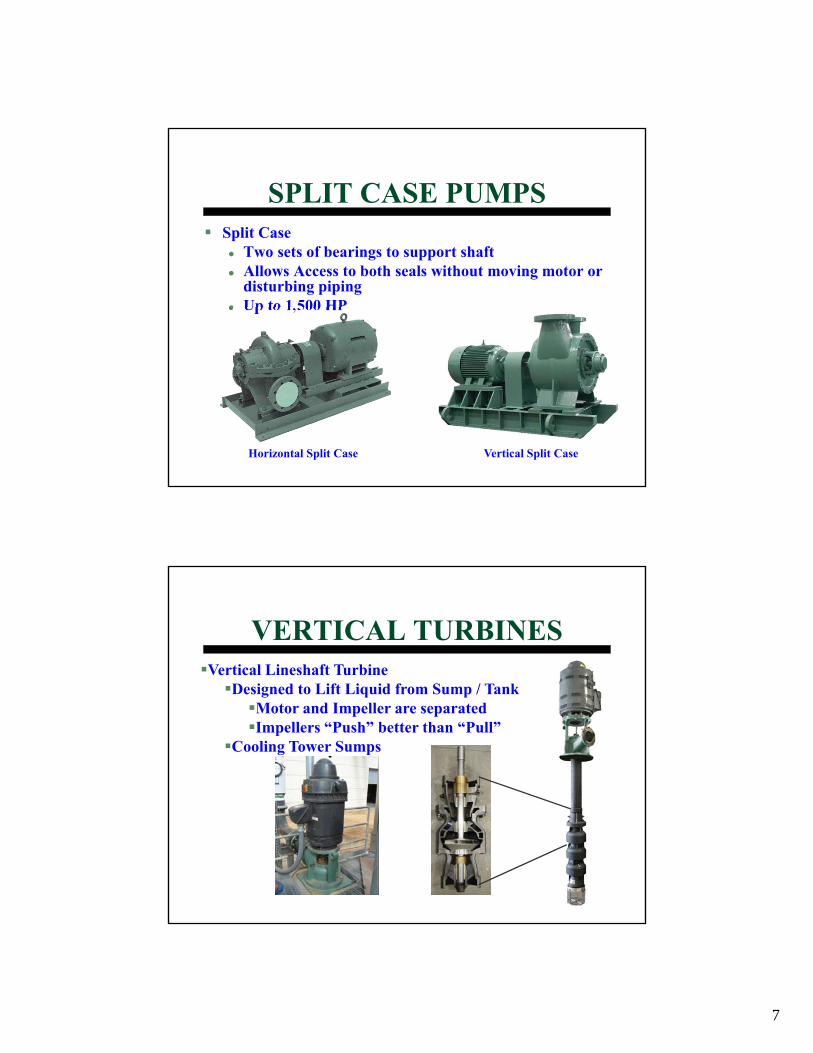
SPLIT CASE PUMPSSplit Case
Two sets of bearings to support shaftAllows Access to both seals without moving motor or disturbing pipingUp to 1,500 HP
Horizontal Split Case Vertical Split Case
VERTICAL TURBINESVertical Lineshaft Turbine
Designed to Lift Liquid from Sump / TankMotor and Impeller are separatedImpellers “Push” better than “Pull”
Cooling Tower Sumps

8
NEW “SMART” PUMPSSpeed varies without sensorsHigh Efficiency ECM
Electronically Commutated MotorA.k.a. DC Brushless Motor
Integral VFDSophisticated ElectronicsResidential to Light Commercial
TYPE GPM HD (FT.) HP RPM
HORIZ. IN-LINE 20 - 375 10 - 75 ¼ - 3 1760, 3500
END SUCTION 40 – 4,000 10 - 400 ⅓ - 200 1160, 1760, 3500
VERTICAL IN-LINE 40 – 12,000 10 - 400 ¼ - 600 1160, 1760, 3500
SPLIT CASE 100 – 18,000 20 - 500 3 – 1,500 1160, 1760, 3500
VERTICAL TURBINE 20 – 6,000 10 - 150 ½ - 150 1160, 1760
TYPICALCAPACITIES
9
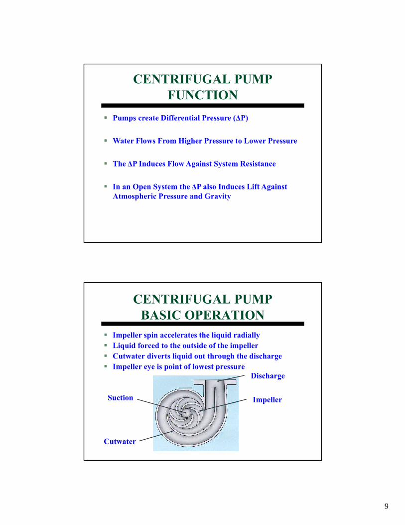
Pumps create Differential Pressure (ΔP)
Water Flows From Higher Pressure to Lower Pressure
The ΔP Induces Flow Against System Resistance
In an Open System the ΔP also Induces Lift Against Atmospheric Pressure and Gravity
CENTRIFUGAL PUMPFUNCTION
CENTRIFUGAL PUMP BASIC OPERATION
Impeller spin accelerates the liquid radiallyLiquid forced to the outside of the impellerCutwater diverts liquid out through the dischargeImpeller eye is point of lowest pressure
Impeller
Discharge
Suction
Cutwater
10
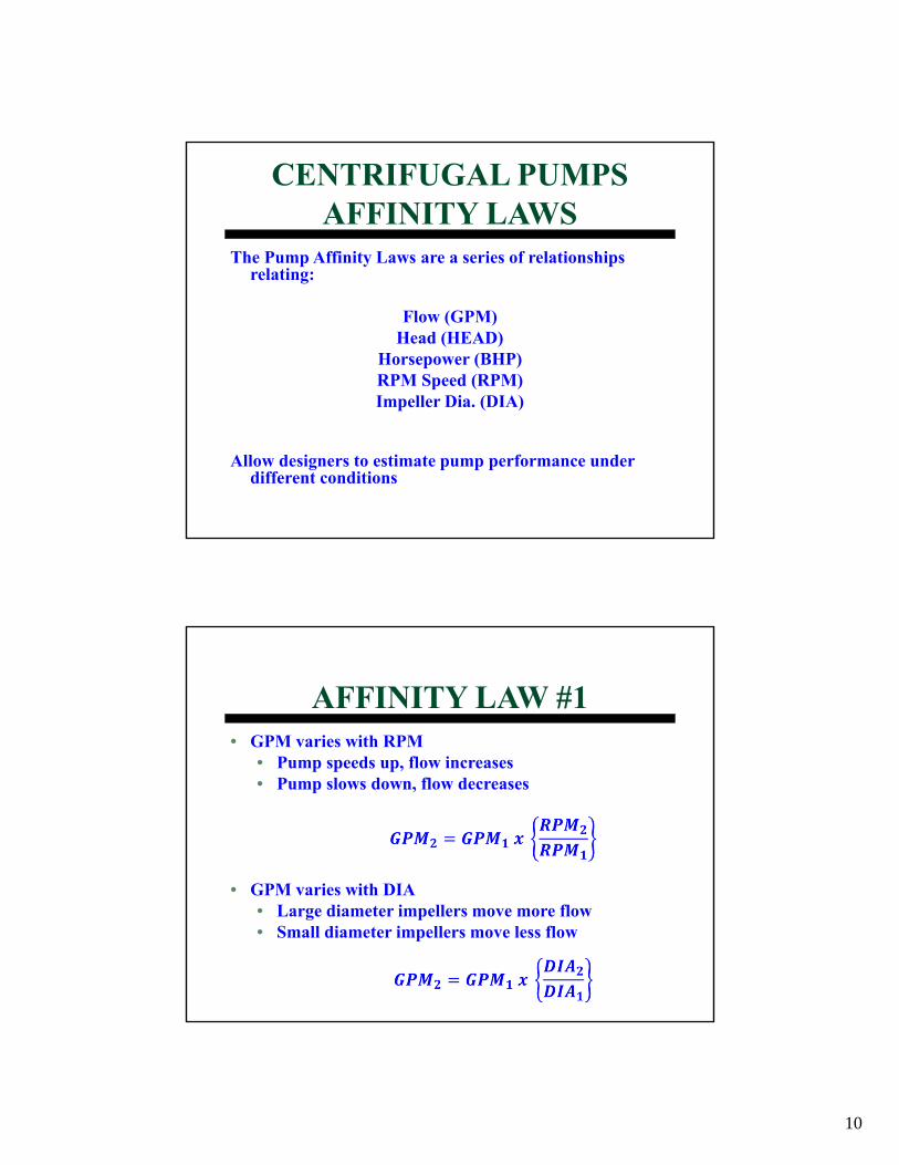
The Pump Affinity Laws are a series of relationships relating:
Flow (GPM)Head (HEAD)
Horsepower (BHP)RPM Speed (RPM)Impeller Dia. (DIA)
Allow designers to estimate pump performance under different conditions
CENTRIFUGAL PUMPSAFFINITY LAWS
• GPM varies with RPM• Pump speeds up, flow increases• Pump slows down, flow decreases
• GPM varies with DIA• Large diameter impellers move more flow• Small diameter impellers move less flow
AFFINITY LAW #1
11
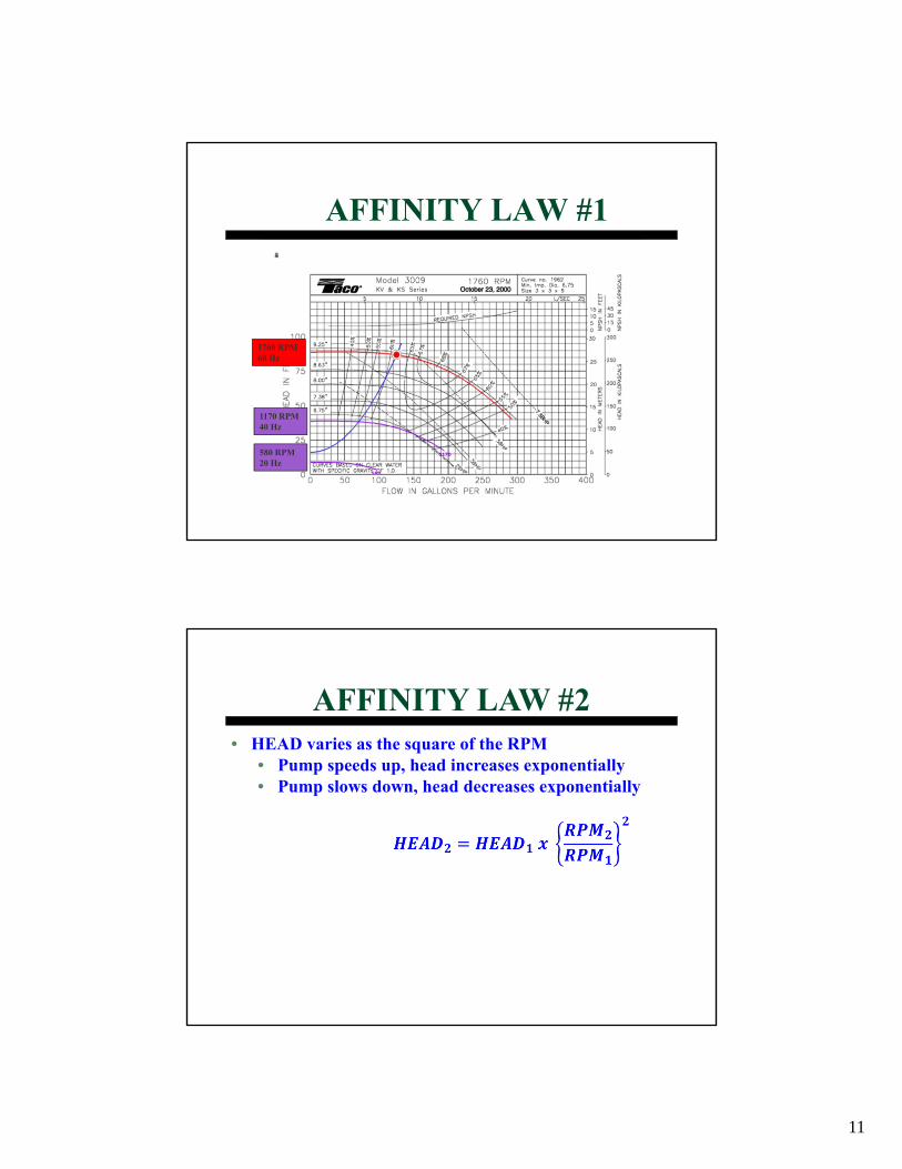
AFFINITY LAW #1
1760 RPM60 Hz
1170 RPM40 Hz
580 RPM20 Hz
• HEAD varies as the square of the RPM• Pump speeds up, head increases exponentially• Pump slows down, head decreases exponentially
AFFINITY LAW #2
12
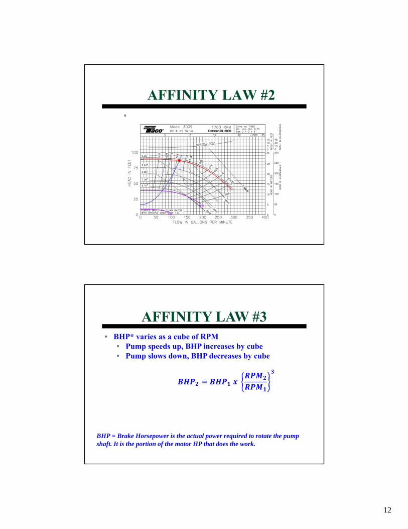
AFFINITY LAW #2
• BHP* varies as a cube of RPM• Pump speeds up, BHP increases by cube• Pump slows down, BHP decreases by cube
AFFINITY LAW #3
BHP = Brake Horsepower is the actual power required to rotate the pump shaft. It is the portion of the motor HP that does the work.
13
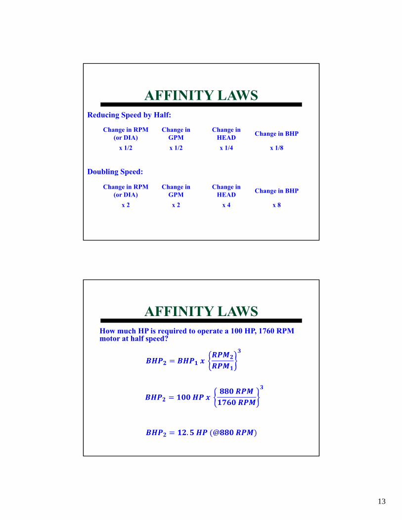
AFFINITY LAWS
Change in RPM (or DIA)
Change in GPM
Change in HEAD Change in BHP
x 1/2 x 1/2 x 1/4 x 1/8
Reducing Speed by Half:
Doubling Speed:
Change in RPM (or DIA)
Change in GPM
Change in HEAD Change in BHP
x 2 x 2 x 4 x 8
AFFINITY LAWSHow much HP is required to operate a 100 HP, 1760 RPM motor at half speed?
14
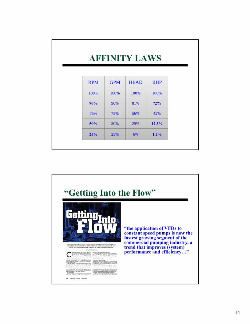
AFFINITY LAWS
RPM GPM HEAD BHP
100% 100% 100% 100%
90% 90% 81% 72%
75% 75% 56% 42%
50% 50% 25% 12.5%
25% 25% 6% 1.2%
“Getting Into the Flow”
“the application of VFDs to constant speed pumps is now the fastest growing segment of the commercial pumping industry, a trend that improves (system) performance and efficiency…”
15
• Soft Start• Same cost as a motor starter• Gentler on motors• Reduces inrush current
• Balancing without multi-purpose valve• Significant energy saving opportunity
• Variable Flow• Flow varies according to demand• Ultimate energy savings
WHY VFDs on PUMPS
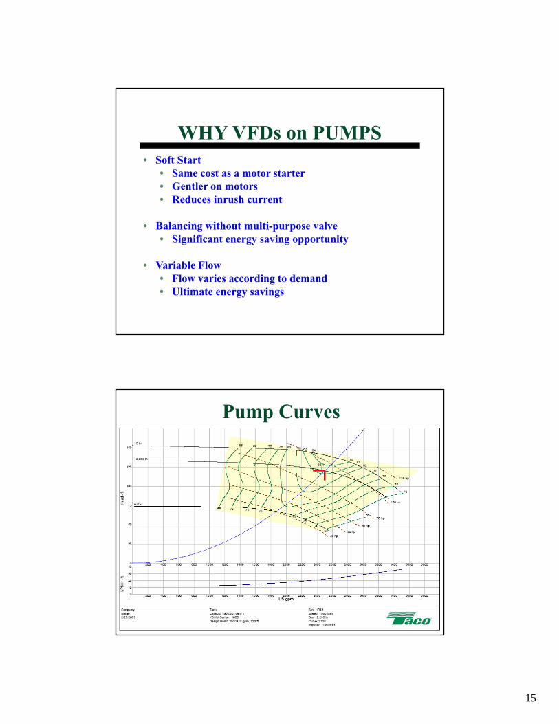
Pump Curves
16
200
100
10 0 20 0 30 0 40 0 50 0 60 0 70 0
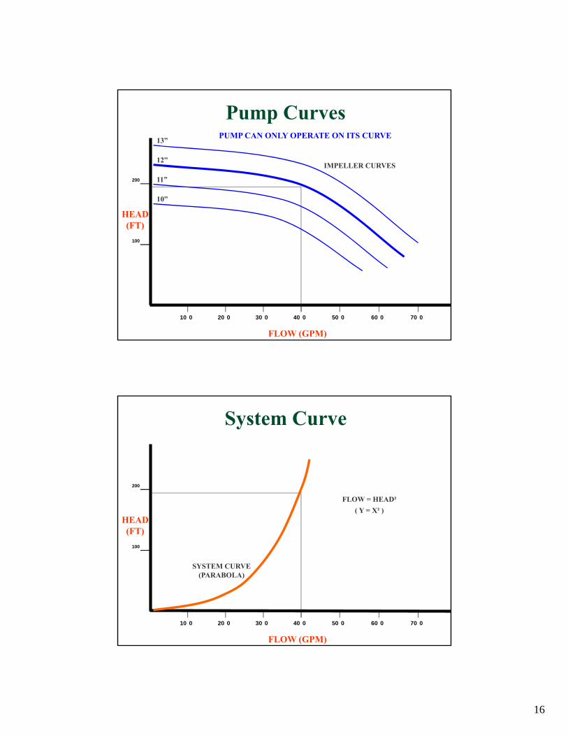
PUMP CAN ONLY OPERATE ON ITS CURVE
IMPELLER CURVES
FLOW (GPM)
HEAD(FT)
Pump Curves
10”
13”
12”
11”
200
100
10 0 20 0 30 0 40 0 50 0 60 0 70 0
SYSTEM CURVE(PARABOLA)
FLOW (GPM)
HEAD(FT)
System Curve
FLOW = HEAD²( Y = X² )
17
200
100
10 0 20 0 30 0 40 0 50 0 60 0 70 0
10 15 20
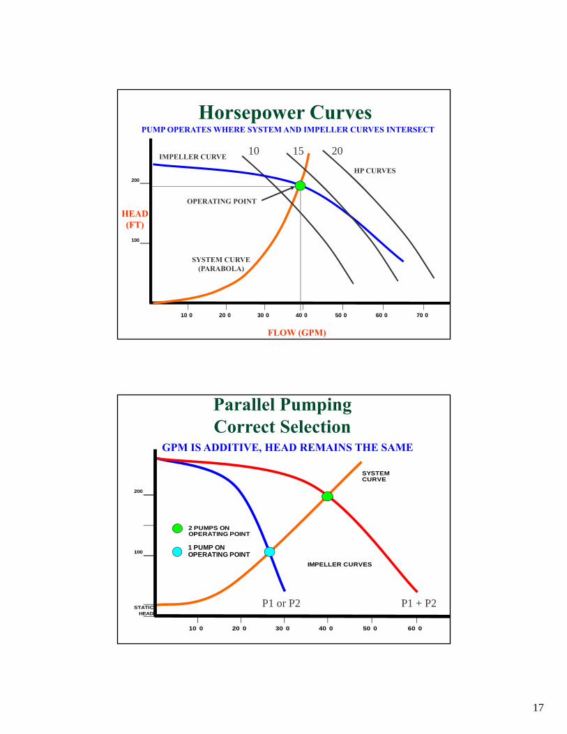
PUMP OPERATES WHERE SYSTEM AND IMPELLER CURVES INTERSECT
HP CURVES
IMPELLER CURVE
SYSTEM CURVE(PARABOLA)
FLOW (GPM)
HEAD(FT)
Horsepower Curves
OPERATING POINT
SYSTEM CURVE
200
2 PUMPS ON OPERATING POINT
100
IMPELLER CURVES
STATICHEAD
10 0 20 0 30 0 40 0 50 0 60 0
GPM IS ADDITIVE, HEAD REMAINS THE SAME
P1 or P2 P1 + P2
1 PUMP ON OPERATING POINT
Parallel PumpingCorrect Selection
18
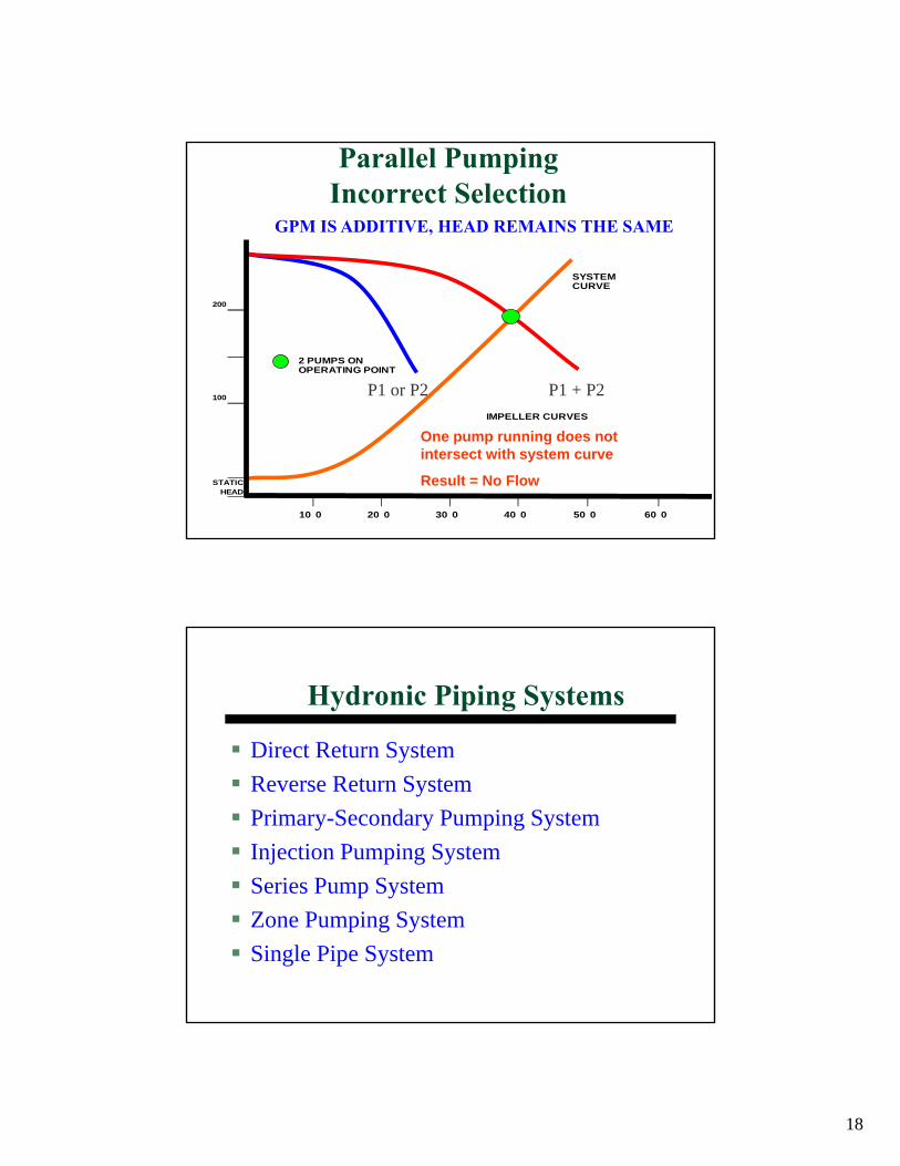
SYSTEM CURVE
200
2 PUMPS ON OPERATING POINT
100
IMPELLER CURVES
STATICHEAD
10 0 20 0 30 0 40 0 50 0 60 0
GPM IS ADDITIVE, HEAD REMAINS THE SAME
P1 or P2 P1 + P2
Parallel PumpingIncorrect Selection
One pump running does not intersect with system curve
Result = No Flow
Hydronic Piping Systems
Direct Return SystemReverse Return SystemPrimary-Secondary Pumping SystemInjection Pumping SystemSeries Pump SystemZone Pumping SystemSingle Pipe System
19
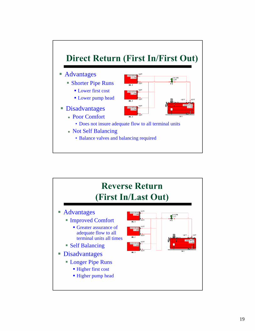
Direct Return (First In/First Out)
AdvantagesShorter Pipe Runs
Lower first costLower pump head
DisadvantagesPoor Comfort
• Does not insure adequate flow to all terminal unitsNot Self Balancing
• Balance valves and balancing required
Reverse Return(First In/Last Out)
AdvantagesImproved Comfort
Greater assurance of adequate flow to all terminal units all times
Self BalancingDisadvantages
Longer Pipe RunsHigher first costHigher pump head
20
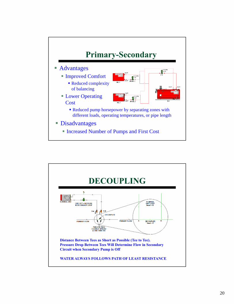
Primary-SecondaryAdvantages
Improved Comfort Reduced complexity of balancing
Lower Operating Cost
Reduced pump horsepower by separating zones with different loads, operating temperatures, or pipe length
DisadvantagesIncreased Number of Pumps and First Cost
DECOUPLING
Distance Between Tees as Short as Possible (Tee to Tee).Pressure Drop Between Tees Will Determine Flow in Secondary Circuit when Secondary Pump is Off
WATER ALWAYS FOLLOWS PATH OF LEAST RESISTANCE
21
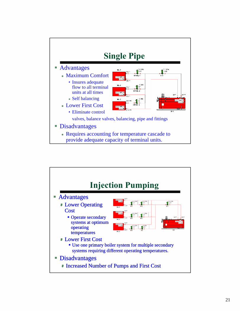
Single Pipe
valves, balance valves, balancing, pipe and fittings
DisadvantagesRequires accounting for temperature cascade to provide adequate capacity of terminal units.
AdvantagesMaximum Comfort
• Insures adequate flow to all terminal units at all timesSelf balancing
Lower First Cost • Eliminate control
Injection PumpingAdvantages
Lower Operating Cost
• Operate secondary systems at optimum operating temperatures
Lower First Cost• Use one primary boiler system for multiple secondary
systems requiring different operating temperatures.
DisadvantagesIncreased Number of Pumps and First Cost
AdvantagesLower Operating Cost
Operate secondary systems at optimum operating temperatures
Lower First CostUse one primary boiler system for multiple secondary systems requiring different operating temperatures.
DisadvantagesIncreased Number of Pumps and First Cost
22
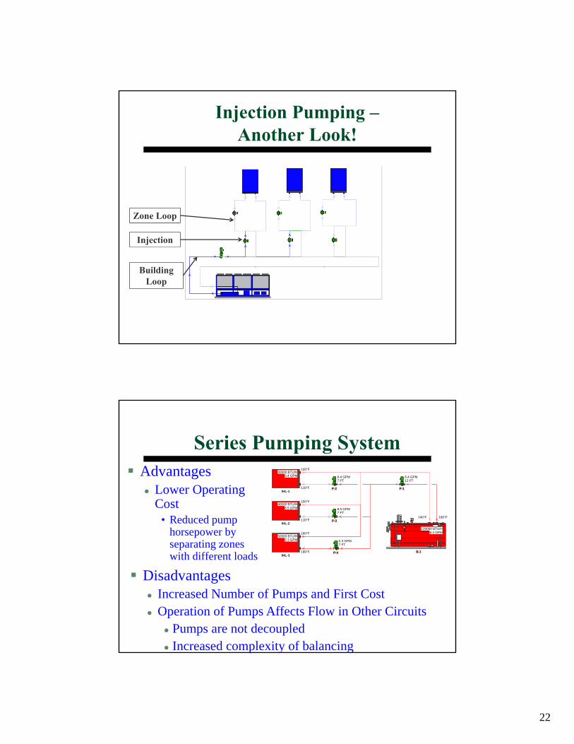
Injection Pumping –Another Look!
Zone Loop
Building Loop
Injection
Series Pumping SystemAdvantages
Lower Operating Cost
• Reduced pump horsepower by separating zones with different loads
DisadvantagesIncreased Number of Pumps and First CostOperation of Pumps Affects Flow in Other Circuits
Pumps are not decoupledIncreased complexity of balancing
IHL-1
100°F
110°F
30000 BTU/H6.4 GPM
IHL-2
100°F
110°F
40000 BTU/H8.5 GPM
IHL-3
160°F
180°F
50000 BTU/H5.3 GPM
B-1
180°F
120000 BTU/H6.4 GPM
140°F
P-1
6.4 GPM12 FT
P-2
6.4 GPM7 FT
P-3
8.5 GPM7 FT
P-4
5.3 GPM7 FT
23
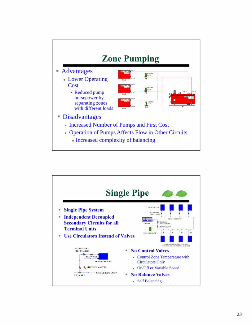
Zone PumpingAdvantages
Lower Operating Cost
• Reduced pump horsepower by separating zones with different loads
DisadvantagesIncreased Number of Pumps and First CostOperation of Pumps Affects Flow in Other Circuits
Increased complexity of balancing
IHL-1
100°F
110°F
30000 BTU/H6.4 GPM
IHL-2
100°F
110°F
40000 BTU/H8.5 GPM
IHL-3
160°F
180°F
50000 BTU/H5.3 GPM
B-1
180°F
120000 BTU/H6.4 GPM
140°F
P-1
6.4 GPM12 FT
P-2
8.5 GPM12 FT
P-3
5.3 GPM12 FT
Single Pipe
Single Pipe SystemIndependent Decoupled Secondary Circuits for all Terminal UnitsUse Circulators Instead of Valves
No Control ValvesControl Zone Temperature with Circulators OnlyOn/Off or Variable Speed
No Balance ValvesSelf Balancing

24
Next Generation Green Piping Systems
Integrated Piping SystemsHeating / Cooling / Fire Protection (Condenser Water)
• Trade Names – Tri Water
Cooling / Fire Protection (Chilled Water)• Trade Names – Total Comfort Solution, Ultimate Comfort Systems
Cooling / Domestic Cold Water (Chilled Water)• Trade Names – Total Comfort Solution
Heating / Domestic Hot Water (Hot Water)• Trade Names – Aqua Therm, Hydro Heat, Total Comfort Solution,
Ultimate Comfort Systems
Less Materials
Next Generation Green Piping Systems
Single Pipe LoadMatch® HVAC/Fire Protection Integrated Piping Main

25
Thank You!