Basic Ethernet/IP Lab - Rockwell Automation · PDF file3 of 62 About this lab Welcome to the...
62
L02 - Applying Basic EtherNet/IP Features in Converged Plant-wide Ethernet Architectures For Classroom Use Only!
Transcript of Basic Ethernet/IP Lab - Rockwell Automation · PDF file3 of 62 About this lab Welcome to the...

L02 - Applying Basic EtherNet/IP Features in Converged Plant-wide Ethernet Architectures
For Classroom Use Only!

Important User Information
This documentation, whether, illustrative, printed, “online” or electronic (hereinafter “Documentation”) is intended for use only as a learning aid when using Rockwell Automation approved demonstration hardware, software and firmware. The Documentation should only be used as a learning tool by qualified professionals. The variety of uses for the hardware, software and firmware (hereinafter “Products”) described in this Documentation, mandates that those responsible for the application and use of those Products must satisfy themselves that all necessary steps have been taken to ensure that each application and actual use meets all performance and safety requirements, including any applicable laws, regulations, codes and standards in addition to any applicable technical documents. In no event will Rockwell Automation, Inc., or any of its affiliate or subsidiary companies (hereinafter “Rockwell Automation”) be responsible or liable for any indirect or consequential damages resulting from the use or application of the Products described in this Documentation. Rockwell Automation does not assume responsibility or liability for damages of any kind based on the alleged use of, or reliance on, this Documentation. No patent liability is assumed by Rockwell Automation with respect to use of information, circuits, equipment, or software described in the Documentation.
Except as specifically agreed in writing as part of a maintenance or support contract, equipment users are responsible for:
• properly using, calibrating, operating, monitoring and maintaining all Products consistent with all Rockwell Automation
or third-party provided instructions, warnings, recommendations and documentation;
• ensuring that only properly trained personnel use, operate and maintain the Products at all times;
• staying informed of all Product updates and alerts and implementing all updates and fixes; and • all other factors affecting the Products that are outside of the direct control of Rockwell Automation.
Reproduction of the contents of the Documentation, in whole or in part, without written permission of Rockwell Automation is prohibited. Throughout this manual we use the following notes to make you aware of safety considerations:
Identifies information about practices or circumstances that can cause an explosion in a hazardous environment, which may lead to personal injury or death, property damage, or economic loss.
Identifies information that is critical for successful application and understanding of the product.
Identifies information about practices or circumstances that can lead to personal injury or death, property damage, or economic loss. Attentions help you: • identify a hazard • avoid a hazard • recognize the consequence
Labels may be located on or inside the drive to alert people that dangerous voltage may be present.
Labels may be located on or inside the drive to alert people that surfaces may be dangerous temperatures.
N999 – Your lab title goes here
Presenter: <<Your name>> <<Your business group>>

3 of 62
About this lab
Welcome to the “Applying Basic EtherNet/IP Features in Converged Plant-wide Ethernet Architectures” Lab. The Stratix 5700 and
Stratix 8000 are Rockwell Automation Managed Ethernet Switches that utilizes Cisco technology. These switches offers the Best
of Cisco and the Best of Allen-Bradley. These products are designed to help ease deployment of your Ethernet networks on
machines and the plant floor.
The Stratix 5700 and Stratix 8000 switch lines use the Cisco Catalyst switch architecture and feature set, along with powerful
configuration tools, helping to provide secure integration with the enterprise network and making IT professionals feel at home.
Both the Stratix 5700 and 8000 Switches allow for easy setup and comprehensive diagnostics from within the Rockwell
Automation Integrated Architecture. These switches can be configured using Studio 5000 programming software. They also
automatically generate Logix tags for integrated diagnostics and include FactoryTalk View faceplates for status monitoring and
alarming. Together these features provide for an easy integration of networking devices into control and automation architectures.
Labs 1-3 will take you through the process of configuring the Stratix 5700 and 8000 Ethernet Switches, which includes Add-On-
Profiles (AOP’s) and Add-On-Instructions (AOI’s) that will extract diagnostic data from the switches and send it to their
corresponding FactoryTalk View SE faceplates.
Lab 4 will take you through the process of configuring a Device Level Ring Topology (DLR), which includes Add-On-Profiles
(AOP’s) and Add-On-Instructions (AOI’s) that will extract diagnostic data from the DLR Ring Supervisor and send it to its
corresponding Factory Talk View SE DLR faceplates.
Labs 1-4 will take approximately 90 minutes to complete.

4 of 62
Tools and Prerequisites PC with Microsoft Internet Explorer V9, V10, V11 or Mozilla Firefox V25, V26 with JavaScript enabled, Studio 5000 v26,
FactoryTalk View Studio 8
Stratix 5700 with FW IOS 15.2(3).EA1 preloaded
Stratix 8000 with FW IOS 15.2(3).EA1 preloaded
Stratix Add On Profile (AOP) v. 8.01.01 for integration into Studio 5000
Stratix 5700 AOI and FactoryTalk View Faceplate v3
Stratix 8000 AOI and FactoryTalk View Faceplate v6
Lab Materials
For this Hands-On lab, we have provided you with the following materials that will allow you to complete the labs in this workbook.
Hardware This hands-on lab uses the following hardware:
ENET 21 Demo Box
Instructor Information
The Instructor Information outlines the setting up, resetting and troubleshooting the Lab station.
Please refer to the Lab Configuration and Setup Guide in the back of the Lab Manual
ETAP Stratix 5700
Stratix 8000
Machine Controller
Line Controller

5 of 62
Connecting your Lab Station
Look at the lab diagram below. This system includes two ControlLogix controllers, a Stratix 8000 and a Stratix 5700, POINT I/O, ETAP, ArmorBlock I/O and a Computer. We have already made the connections for you. Verify and trace all the cables. Note that the numbers on the cables in the demo box may not match numbers on the diagram. Please do not connect the cable to the “Machine” EN2TR Slot 3, Port 2 (Top CLX). This will be done in the Lab 4.
6 of 62
Lab 1: Stratix 5700 and 8000 Hardware Familiarization
About this Lab
In this lab, we will introduce you to the Stratix 5700 and Stratix 8000 Managed Ethernet switches with Cisco technology.
Stratix 5700 Managed Ethernet Switch
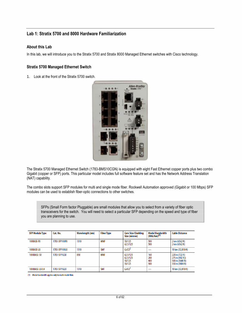
1. Look at the front of the Stratix 5700 switch.
The Stratix 5700 Managed Ethernet Switch (1783-BMS10CGN) is equipped with eight Fast Ethernet copper ports plus two combo Gigabit (copper or SFP) ports. This particular model includes full software feature set and has the Network Address Translation (NAT) capability. The combo slots support SFP modules for multi and single mode fiber. Rockwell Automation approved (Gigabit or 100 Mbps) SFP modules can be used to establish fiber-optic connections to other switches.
SFPs (Small Form factor Pluggable) are small modules that allow you to select from a variety of fiber optic transceivers for the switch. You will need to select a particular SFP depending on the speed and type of fiber you are planning to use.

7 of 62
The Stratix 5700 can be managed via the Device Manager Web interface for configuration, troubleshooting and monitoring. Using this software, real-time information can be viewed. In addition to the Device Manager, the switch can also be managed via the Studio 5000 environment after Express Setup on the switch is complete. Through Device Manager, a Front Panel view of the Stratix 5700 can be observed where switch components are color-coded to indicate state of the switch. An existing fault or error condition can be observed to match the front of the physical switch. System LEDs show status indications similar to the Stratix 8000.
A complete description of the System LEDs can be found in the Device Manager and the Hardware Manual (Publication 1783-UM004).
There are two power connectors on the top right of the switch. You can connect the switch to two separate power sources for redundancy.
Additional connectors on the bottom right provide hardwired contacts for major and minor alarms.
The Express Setup button is located on the top. Express Setup allows you to easily configure the switch for EtherNet/IP networks.
The Console port on the top is a serial connection available on all Cisco hardware. The console port allows direct access to the switch via Cisco’s Command Line Interface (CLI)
The Secure Digital (SD) card slot is located in the bottom. The optional SD card allows you to simplify device replacement by storing switch configuration and firmware.
Stratix 5700 Port Numbering
The Stratix 5700 uses Cisco’s standard port naming convention. Each port name includes:
1. A port ID that consists of port type:
Gigabit Ethernet for Gigabit ports (abbreviated as Gi), and
Fast Ethernet for 10/100 Mbps ports (abbreviated as Fa)
2. Unit number (always 1 for the 5700 platform), and
3. Port number (1-2 for Gigabit ports, 1-18 for all others, depending on catalog numbers)
The Stratix 5700 Managed Ethernet Switch (1783-BMS10CGN) follows this port numbering convention:
8 of 62
Stratix 8000 Managed Ethernet Switch (Base Module)
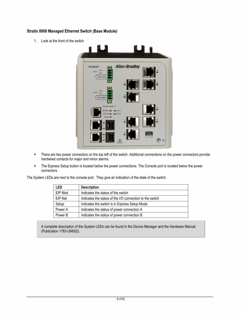
1. Look at the front of the switch
There are two power connectors on the top left of the switch. Additional connections on the power connectors provide hardwired contacts for major and minor alarms.
The Express Setup button is located below the power connections. The Console port is located below the power connectors
The System LEDs are next to the console port. They give an indication of the state of the switch.
LED Description
EIP Mod Indicates the status of the switch
EIP Net Indicates the status of the I/O connection to the switch
Setup Indicates the switch is in Express Setup Mode
Power A Indicates the status of power connection A
Power B Indicates the status of power connection B
A complete description of the System LEDs can be found in the Device Manager and the Hardware Manual (Publication 1783-UM002).

9 of 62
Below the console port are the Gigabit Ethernet ports.
The Stratix 8000 comes with two Gigabit Ethernet ports. There are two connectors for each port; a RJ-45 and an SFP slot. The RJ-45 connector allows you to connect a standard Category 5e or better patch cable. The SFP slot allows you to select the right fiber optic transceiver for your application.
The copper Gigabit Ethernet port support speeds of 10, 100, and 1000 Mbps.
SFPs (Small Form factor Pluggable) are small modules that allow you to select from a variety of fiber optic transceivers for the switch. You will need to select different SFPs depending on the speed and type of fiber you plan on using. You must use the Rockwell Automation ruggedized industrial SFPs in the Stratix 8000.
The 10/100 Base-TX ports are located on the right side of the switch. The Stratix 8000 base module is available with either four or eight 10/100 ports on the base module. The eight port version is used in this lab.
The grounding lug is located at the lower right corner of the switch.
2. Look at the right side of the switch
The side cover can be removed to install optional expansion modules. Copper, fiber, SFP, and power over Ethernet (PoE) expansion modules can be added to a Stratix 8000 system. Copper and Fiber expansion modules can be combined to provide additional copper and fiber ports on your system.
SFP Expansion modules can add up to 12 fiber ports with the ability to mix and match multimode and single mode SFPs.
PoE modules pass electrical power along with data on Ethernet cabling. This allows a single cable to provide both data connection and electrical power to devices such as wireless access points. There are six catalog numbers for the expansion modules:
The switch can support up to two expansion modules.

10 of 62
3. Feel the bottom back side of the switch
The clear plastic tab on the bottom of the switch is the Compact Flash card. The Stratix 8000 stores the configuration and Operating System on the Compact Flash card. In the event of a hardware failure the Compact Flash card can be moved to the replacement switch. The replacement switch will boot with the correct configuration and Operating System.
The Stratix 8000 uses the Cisco Internetworking Operating System (IOS). At boot-up the switch copies the configuration and IOS into RAM. The Compact Flash card can be removed while the switch is running. However, you will not be able to save the configuration or boot the switch without the Compact Flash card installed.
Stratix 8000 Port Numbering
The Stratix 8000 uses Cisco’s standard port naming convention. Each port name has three parts; the type of interface, the
module number, and the port number.
Port Name Interface Type Module Port
gi1/1 Gigabit Ethernet 1 1
fa1/1 Fast Ethernet 1 1
fa1/5 Fast Ethernet 1 5
fa2/3 Fast Ethernet 2 3
fa3/7 Fast Ethernet 3 7
The ports are numbered from top to bottom and left to right. The port numbering for each interface type always starts at one.
Each switch has a port gi1/1 and a port fa1/1. The base unit is module one. The first expansion module is number two and the
second expansion module is number three.
You may see the terms “port” and “interface” used interchangeably. If you are configuring the switch using the Studio 5000 or Device Manger the term “port” is used. If you are configuring the switch via the CLI the term “interface” is used.

11 of 62
Lab 2: Configuring a Stratix 5700 Switch and reviewing its Add-On-Profile (AOP) and Controller Tags.
About This Lab
In the past a Control Engineer would have inserted Ethernet modules and Remote I/O devices in the I/O Configuration Tree of the
Studio 5000 and operated with little regard to the health or status of the network and switches until there was a problem. Rockwell
Automation has taken a more proactive approach to this problem and has developed a variety of Ethernet Switches that have the
Common Industrial Protocol (CIP) built into the product. This gives us the ability to retrieve switch and network diagnostic data
directly from the switch via its Add-on-Profiles (AOP’s) into the controller so we can make informed decisions when
troubleshooting a problem instead of guessing where the problem might be.
In this lab you will add the Stratix 5700 AOP to a preconfigured Studio 5000 project. You will accomplish the following tasks:
Adding the Stratix 5700 to the I/O tree.
Exploring the Stratix 5700 and 8000 Add-on Profile and their corresponding tags.
Configuring the Stratix 5700 using the Add-on Profile
To save time, the project and tags have already been created for you.
Adding the Stratix 5700 to the I/O Configuration Tree of Studio 5000.
In this section, you will add the Stratix 5700 to the I/O Tree.
1. Open the Logix Files folder on the desktop and double-click on the Studio 5000 project
Bottom_CLX_Line_START.acd. Make sure you select the right project file for this step.
2. REVIEW: In the I/O Configuration tree, you will notice a few modules have already been inserted for you. These
modules were inserted to save time and will be used in future labs. You will do the same exercise when
inserting the Stratix 5700 switch. Why are we configuring two different switches in the architecture? Let’s say
the ControlLogix controller happens to be in a different cabinet than the I/O. Each cabinet has its own switch
and you want to read diagnostic status from each switch, hence the need to configure two different switches in
the Studio 5000 I/O Configuration tree.

12 of 62
3. In the I/O tree, right click on Ethernet below the Local 1756-EN2TR module, and select New Module.
4. Under the Catalog tab, uncheck all modules, then re-check Communications and Select the 1783-BMS10CGN
Stratix 5700 10 Port Managed Switch module and Click Create.

13 of 62
5. The Add-on Profile window will open. Populate the appropriate data as seen below.
Name: Stratix_5700
IP Address: 192.168.1.2
6. Click the Change button.
7. Change Revision field to 5.1.
Type ‘rockwell’ in the Data Connection Password field.
Change the Connection type from Input Data to Data.
The Stratix 5700 has input and output tags. Multiple controllers can read the input tags at the same time, but only one controller can “own” the I/O and write to the output tags of the switch. Setting the connection to Data enables the controller to read the input tags and “own” the output tags.
14 of 62
8. Click OK to close the Module Definition window.
9. Type ‘rockwell’ in the Password Confirmation window.
10. Click OK to close the window.
11. Click Yes to acknowledge the change to the module definition.
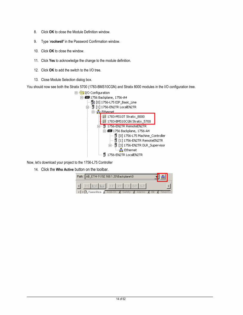
12. Click OK to add the switch to the I/O tree.
13. Close Module Selection dialog box.
You should now see both the Stratix 5700 (1783-BMS10CGN) and Stratix 8000 modules in the I/O configuration tree.
Now, let’s download your project to the 1756-L75 Controller
14. Click the Who Active button on the toolbar.

15 of 62
15. Using the AB_ETH-1 driver, select the 1756-EN2TR module at address 192.168.1.20, then drill down to the (1756-L75
LOGIX5575) in slot 0, Click once to Highlight, then Click Download.
16. Click Download.

16 of 62
17. Click Yes to put controller in Run Mode
If a separate window shown above did not pop up then Click the drop-down in the online toolbar and select Run Mode.
When the I/O light is solid green, this means you are connected to all devices in the I/O tree. If you see the blinking I/O light and warnings in the I/O tree, verify physical connections and IP address settings for the device that is having problems.
Reviewing the Stratix 5700 Add-on-Profile (AOP)
In this section you will learn about the Stratix 5700 Add-on Profile and use it to configure the switch.
1. Double-click on Stratix_5700 in the I/O tree.

17 of 62
2. Select the Connection from the Profile Tree.
The default RPI for the Stratix 5700 connection is 1000ms and it is set to use a unicast data type.
3. Select the Module Info.
This page shows basic information about the module such as product type and fault status.

18 of 62
4. Select the Switch Configuration.
This page shows the details of the IP configuration of the switch. There are also fields that allow you to enter contact names or the location of the equipment, device name (“host name”).
5. Select the Switch Status.
This page show detailed status information about the switch such as uptime, temperature, utilization, and hardware alarms.

19 of 62
6. Select the Port Configuration.
This page allows you to enable/disable ports and manually configure the speed and duplex on the ports. If the port is set to auto-negotiate, it will display the current speed and duplex. If you would like to manually set speed and duplex, you can uncheck “Auto-Negotiate” here. However, for the purpose of this lab, keep “Auto-Negotiate” enabled.
7. Select the Smartports & VLANs.
This page allows you to assign Smartport roles and VLANs to the ports. Smartports are port configurations that have been optimized by Rockwell Automation and Cisco for EtherNet/IP networks. The following Smartports are currently available:
Automation Device
Desktop for Automation
Switch for Automation
Router for Automation

20 of 62
Phone for Automation
Wireless for Automation
Multiport Automation Device
Virtual Desktop for Automation
You should use Smartports to easily optimize your EtherNet/IP network.
Several of the Smartports have built-in MAC address security. When a device is connected to the port the switch will add the MAC address to the security table. When the device is disconnected, i.e. replaced, the switch will automatically learn the new MAC address and add it to the table. The switch will limit the number of MAC addresses that is allowed on the port (1 for Automation Device and Desktop for Automation, 2 for Virtual Desktop for Automation).
You will notice that ports have already been configured for this lab. For example:
Port Fa1/2 = Automation Device (i.e. 1756-EN2TR)
Port Fa1/3 = Automation Device (i.e. ArmorBlock I/O)
Ports Fa1/7 and Fa1/8 = Multiport Automation Device. This is a requirement for the Device Level Ring.
If the smart port configuration is different, click the Refresh button. If the smart port configuration is still different please
call the lab instructor over to correct this discrepancy.
8. Select the Port Thresholds.
Port thresholds prevent devices from flooding your network with excess traffic. You can limit the broadcast, unicast, and
multicast traffic that can be sent by the device connected to the port. The thresholds can be set to packets per second, bits
per second, or percent utilization. If the threshold is exceeded, the switch will drop traffic below the specified value.

21 of 62
9. Select the Port Security.
Use this page to enable and configure port security. Port security restricts the devices that can connect to the switch port based on their MAC addresses. The MAC address is also known as Ethernet address, physical address, or hardware address. Each node on the network has a unique MAC address assigned to it.
10. Select the Port Status.
The Port Status tab shows you the link status, alarm status and utilization of the ports.

22 of 62
11. Click the Port Diagnostics button for Gi1/1.
The Port Diagnostics window shows detailed Ethernet counters and errors for the port.
12. Close the Port Diagnostics window.
13. Select the Device Level Ring (DLR).
Use this page to enable the DLR on the ring, and to view information about the DLR network. A DLR network is a single-
fault tolerant ring network intended for the interconnection of automation devices without the need for more switches. On
the Device Level Ring (DLR) tab, you can:
Enable DLR on the ring.
Choose the ring ports.
View whether the switch is a ring supervisor.
View whether the switch is operating in a DLR or linear network.
View the status of the network.

23 of 62
View the IP address of the active ring supervisor.
As you see we already prepared switch to be the part of the DLR by enabling the Ring 1 and setting the ports Fa1/7 and
Fa1/8 to be the part of the DLR. We will explore DLR setting in details in the Lab 4.
14. Select the DHCP Pool Display.
The DHCP Pool Display tab will allow a user to enable Dynamic Host Configuration Protocol (DHCP) and to configure and
view up to 15 separate DHCP Address Pools. These pools of IP Addresses are used to automatically configure an end
device with an IP address, as long as the end device is set for DHCP and/or BOOTP. DHCP may be enabled on your
device. However, if a DHCP Pool is not created, addresses will not be served to end devices.
15. Select the DHCP Address Assignment.

24 of 62
Use the DHCP Address Assignment page to view and configure DHCP persistence. Every device in an IP-based network must have a unique IP address. The DHCP automatically assigns IP address information from a pool of available addresses to newly connected devices (DHCP clients) in the network. If a device leaves and then re-joins the network, the device receives the next available IP address, which might or might not be the same address that it had before.
The switch can be set to operate as a DHCP server to provide DHCP persistence. With DHCP persistence, you can assign a specific IP address to each port, ensuring that the device attached to a given port will have the same address, even if power cycled or replaced for maintenance.
16. Select Time Sync Configuration.
Use this page to synchronize the ports through Time Sync Configuration.
Time Synchronization synchronizes with nanosecond accuracy the real-time clocks of the devices in a network. Using the
best master clock selection, the switch identifies the switch port that is connected to a device with the best clock source. The
switch then synchronized its internal clock with the best clock source and the switch port is set to master state. The most
precise clock source in the network is referred to as the grandmaster clock. The data is only displayed when the module is
online. You can only configure time synchronization when the module is online and the Enable Time Synchronization check
box is selected.

25 of 62
17. Select the Time Sync Information.
Use the Time Sync Information page to view current information about the real-time clocks in the network. The data is only
displayed if the module is online, or the CIP (Common Industrial Protocol) Sync Time Synchronization feature is enabled.
CIP Sync Time Synchronization is enabled or disabled on the Time Sync Configuration page.
18. Select the NAT.
Use this page to create and modify Network Address Translation (NAT) instances.
A NAT instance contains entries that define each address translation, as well as other configuration parameters.
We will explore NAT functionality in the Advanced Ethernet/IP labs.

26 of 62
19. Select the SD Flash Sync.
Use this page to copy configuration files and the switch operating system to and from an SD flash card when an SD card is
present.
20. Select the Save/Restore tab.
The Save/Restore tab allows you to save the switch configuration to the Studio 5000 project. It also allows you to export the configuration files to the local computer.
The “config.text” file is a text file that contains the configuration for the switch.
The “vlan.dat” file is a binary file that contains the VLAN configuration for the switch.

27 of 62
21. Click the Upload button. When prompted for a Password enter ‘rockwell’.
22. Click OK to acknowledge the successful upload. You have now saved the switch configuration to the Studio 5000
project.
23. Click OK to close the Module Properties window.
Stratix 5700 Studio 5000 Module Tags
In this section, you will look at the tags that were added by the Stratix 5700 Add-on Profile.
1. In the Controller organizer, double-click on the Controller Tags. You will notice the tags are in alphabetical order. To
see the Stratix 5700 tags, browse to the Stratix_5700:I. tags.
2. Expand the Stratix_5700:I tags.

28 of 62
There are five different types of input tags available:
Fault/Status Tags
The Fault, MajorAlarmRelay, and MinorAlarmRelay tags can be used to notify your application of an error condition on the network. The MutlicastGroupCount tag gives the number of active multicast groups across all ports on the switch.
Port Connected Tags
The port connected tags can be used by your application to verify that critical devices are connected to the network. A good example is monitoring a ring of switches. A switch ring can survive a single link failure. Your application can monitor the ports that make up the ring and notify the operator or maintenance if one of them goes down.
Unauthorized Device Tags
If you are using port security in your network, the unauthorized device tags can be used to notify the operator or maintenance that an unauthorized device has been detected on the network.
Port Threshold Tags
The port threshold tags can notify your application that a device is misbehaving on your network and a port threshold is being exceeded.
Port Utilization Tags
The port utilization tags give you percent utilization of each of the ports. These can be used to take a baseline for your application and alert you if the application deviates from the baseline.

29 of 62
3. Expand the Stratix_5700:O tags.
The output tags are used to enable or disable ports on the switch. A good example of this is a maintenance port on the side of a cabinet. The HMI application can be used to ensure that the port is disabled unless a maintenance person enters a password.
Use caution when using output tags in your program. If you disable a port with the output tag the only way to enable the port is with the output tag. If you try to enable the port using the Add-on Profile, Device Manager, CNA, SNMP, or CLI the controller will shut the port down again.
This means if you use a tag to shut down the port connected to the controller the controller will need to be taken offline before the port can be enabled.
4. Close the Controller Tags window.
5. Save the project. Select Yes if prompted to Upload Tags.
6. Click the green controller icon and Click the Go Offline selection.

30 of 62
Reviewing the Stratix 8000 Add-on Profile and Module Tags
In the interest of saving time, because we would like you to finish the entire lab, we are bypassing the review of the Stratix 8000
AOP and module tags. They are very similar to the Stratix 5700 AOP and tags. But if you would like to review this material later,
please feel free to do so at the end of the lab.

31 of 62
Lab 3: Stratix 5700/8000 AOI and Diagnostic Faceplates
About this Lab
In this lab you will add the Stratix 5700 Add-on-Instruction (AOI) to the project. You will then review the Stratix 5700 and 8000
Faceplate using FactoryTalk View SE. The AOI feature was added to V16 of RSLogix5000 software and is a way for engineers to
encapsulate application code and essentially create his/her own instruction to be used anywhere in the project. The AOI feature
was used by RA engineers to create instructions that retrieve diagnostic data from an Ethernet device, in this case the Stratix
5700 and 8000 switches, and send this data to an HMI running FTViewSE or ME where it will be displayed in what we call a
faceplate. These faceplates will be reviewed in the lab later.
Inserting, Configuring, and Reviewing, the Stratix 8000 Faceplate AOI in Studio 5000
Review: To save time, the Stratix 8000 Faceplate AOI has already been added to the project in ladder code and can be seen in
the Main Routine on Rung 3.
32 of 62
Inserting, Configuring, and Reviewing, the Stratix 5700 Faceplate AOI in Studio 5000
Stratix 5700 Faceplate AOI distributed as pre-configure ladder Rung. This allows to import the AOI, all required data types and
preconfigured Message instructions in one simple step that can be performed Online.
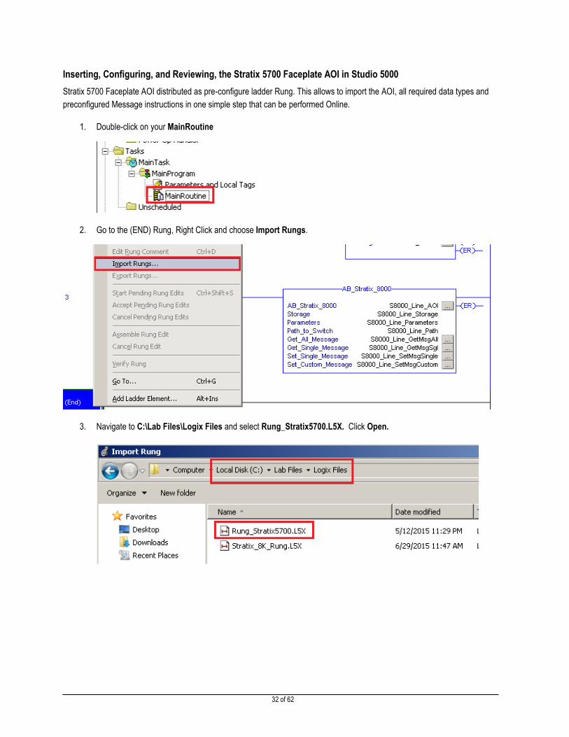
1. Double-click on your MainRoutine
2. Go to the (END) Rung, Right Click and choose Import Rungs.
3. Navigate to C:\Lab Files\Logix Files and select Rung_Stratix5700.L5X. Click Open.

33 of 62
4. Import Configuration Dialog will open. Select Tags from the Import Content tree.
5. Click Find/Replace. This Dialog allows user to change tag names to match actual equipment. In this example we will
use tag name prefix S5700_Machine for all associated tags.
Change tag names as shown below and Click Replace All.

34 of 62
6. Clock Close and verify Final Name column. Click Ok
7. Highlight S5700_Machine_Path tag, Right Click, and select Monitor “S5700_Machine_Path”

35 of 62
8. Click Ellipses button, change path to 1,1,2,192.168.1.2 then click Ok
9. Save the project.
10. Go online and download the project. Change to Remote Run when prompted.

36 of 62
Reviewing the Stratix 5700 Faceplate
1. Double-click the (Shortcut Basic Lab EtherNetIP.cli) button, which can be found on the desktop. The
FactoryTalk View Client application will launch. This may take a few minutes.
Note: Connections and faceplate programming for the Device Level Ring area is not yet complete. You will do it in the
Lab 4. Do not click on the “DLR Tool” button this point.

37 of 62
2. Click on the Stratix 5700 picture.
3. Click the Home Button.
What you will see is the Home Page of the Stratix 5700 Faceplate. The Home page will display IP Address Settings,
Operating Temp of the Switch, how long the switch has been running since it was last powered down and other switch
information. The Home Page Window, and all other windows, will display Port Status along with a Port Status Color Key to
inform to user if the port is Active, Inactive, Disabled, and/or if an unauthorized device has been attached to the port.

38 of 62
4. Click on the Scroll Up button to select port Fa1/3. Click on the Port Information Button .
The Port Information tab will display specific port information like Utilization, Speed, Duplex, Link Status, and if the port is set
for Auto negotiation Mode. It also displays input/output statistics. By clicking around on the different ports you will notice that
some have configured Smartports. Recall that we configured these Smartports earlier in Studio 5000.
5. Click on the Trend button .
The Trend Window shows a trend graph of the switch temperature and the utilization of the selected port. Since there is very
little traffic on the network, utilization will be near 0%. Port utilization should never be above 50%. If it is, this may be a sign
of a broadcast storm or other network issues.

39 of 62
6. Click on the Trend Legend Button.
The Trend Legends Window displays min/max Watermarks for Utilization and Switch Temp.
7. Click on the Alarm button.

40 of 62
8. Click on the Broken Wire Test button.
The Broken Wire detection screen is used for Cable Diagnostics. This test will determine if there is a break in the wire. To test this
feature, type the switch password “rockwell”, press Enter and click “Login”. Once your password is successfully validated,
select the port at which you would like to perform cable diagnostics and click the Test button.
Note: if the display says “Invalid password”, make sure that you pressed Enter after typing the password.
You will see the results as shown above (may take up to 40 seconds). “Test Last Run” indicates when the cable diagnostic test
was performed on that specific port. The Status of the cable is shown for each of the pairs (Pair A, B, C, D). The Distance
indicates the distance at which the break is detected. Please note that the distance may not always be very accurate.
9. Close the Stratix 5700 Diagnostic Faceplate Window.

41 of 62
Reviewing the Stratix 5700 Device Manager Web Interface
In this lab we will explore the Stratix 5700 web pages.
1. Click on the Button located on the bottom Left of the FTViewSE Application. This button will launch a web browser and open up a web page for the device at 192.168.1.2.
2. Leave the username filed blank, enter the password: “rockwell” and click OK.
Note: In this case, we are only using a password to log in to the switch. The Stratix 5700 can also be configured to use individual usernames and passwords for enhanced security. Users can be assigned different privilege levels (for example, read-only).
42 of 62
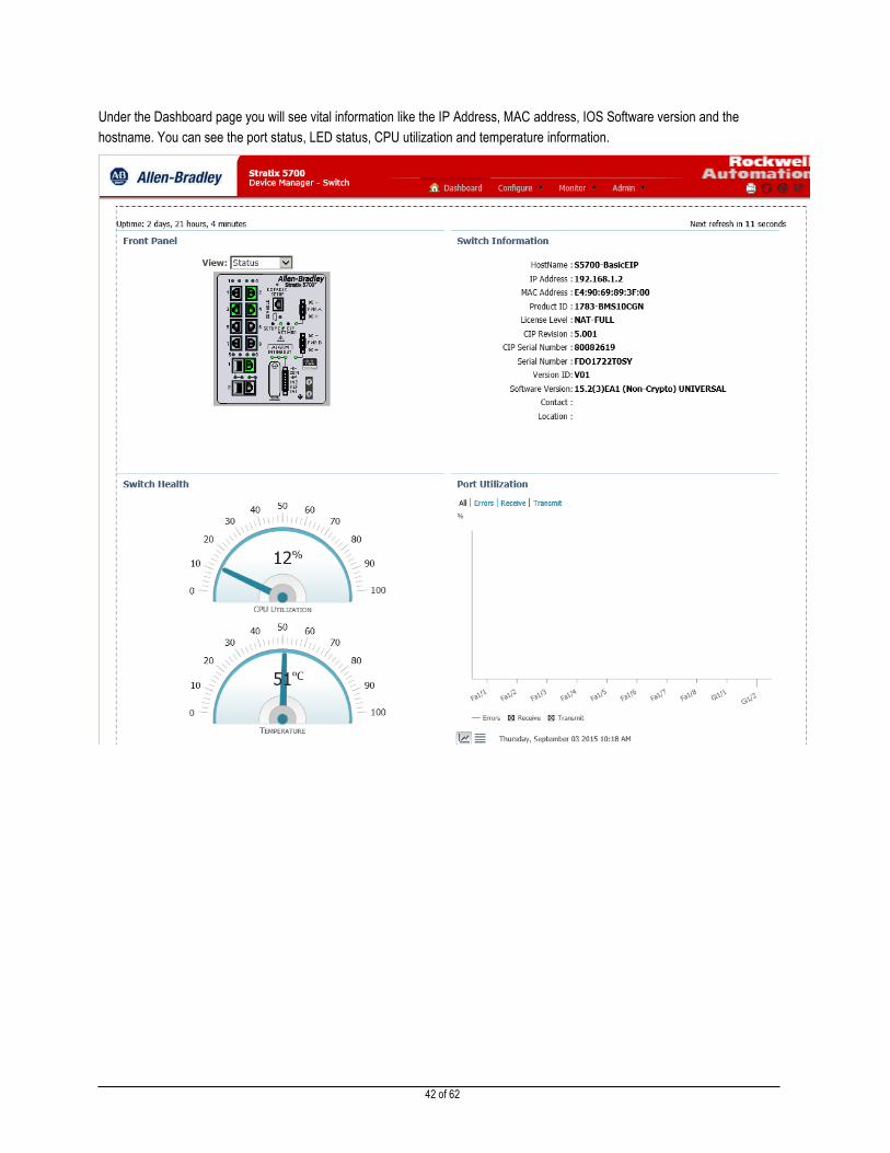
Under the Dashboard page you will see vital information like the IP Address, MAC address, IOS Software version and the
hostname. You can see the port status, LED status, CPU utilization and temperature information.

43 of 62
3. Click on the Configure Tab, then Click on the Smartports page. You should see the assigned Smartports roles for interfaces. You should remember doing this configuration earlier in the AOP.
4. Go ahead and click on other folders and review some other features and functionality associated with the Stratix 5700.
Important: Please do not change or save any configuration. This may cause issues for your lab and/or future labs.
5. Close the Stratix 5700 Web Page when you are finished reviewing it.
Note: Once you have added a Stratix switch to the I/O Tree in Studio 5000, anything that is configured in there will supersede what is configured through the Device Manager (web page). This occurs because of the “CIP” Connection from Studio 5000. Every time your program scans, the settings in the I/O tree are sent to the switch again. This is especially important during initial configuration. If you configure your switch through the web page first, then add to the I/O tree, be sure that you “upload” the configuration from the switch before making additional changes. You’ll recall that we did this step earlier.
Reviewing the Stratix 8000 Faceplate
In the interest of saving time, because we would like you to finish the entire lab, we are bypassing the review of the Stratix 8000
faceplate. It is very similar to the Stratix 5700 faceplate that you viewed earlier. But if you would like to review this material later,
please feel free to do so at the end of the lab.
Reviewing the Stratix 8000 Web Page
In the interest of saving time, because we would like you to finish the entire lab, we are bypassing the review of the Stratix 8000
Device Manager webpage. It is very similar to the Stratix 5700 Device Manager. But if you would like to review this material later,
please feel free to do so at the end of the lab.
44 of 62
Lab 4: Device Level Ring (DLR) Topology
About this lab
In this lab we will introduce you to the products with dual port embedded Ethernet switch technology. The embedded switch
products can be placed in what we call a Device Level Ring or DLR.
A Device Level Ring is created when you connect dual port devices together similar to connecting devices in a daisy- chain
fashion. When the final Ethernet cable is connected from the end DLR device back to the first DLR device, a Linear Topology
becomes a Ring Topology.
An advantage of using a Device Level Ring instead of a Linear/Star Topology is that it provides for network resilience by giving
Ethernet traffic two paths to travel down. So if there is a failure somewhere in the ring, Ethernet packets of information will travel
the opposite direction. And with an assigned Ring Supervisor configured, you will know and understand that a failure occurred and
what two DLR Devices it happened between.
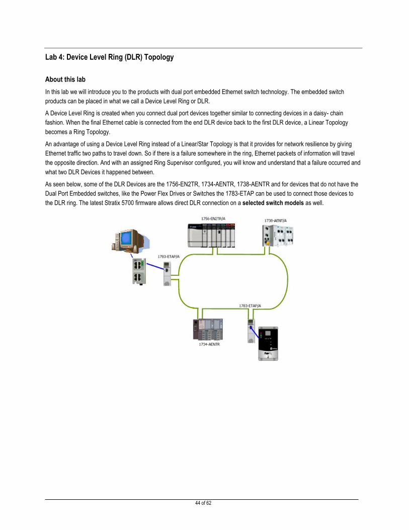
As seen below, some of the DLR Devices are the 1756-EN2TR, 1734-AENTR, 1738-AENTR and for devices that do not have the
Dual Port Embedded switches, like the Power Flex Drives or Switches the 1783-ETAP can be used to connect those devices to
the DLR ring. The latest Stratix 5700 firmware allows direct DLR connection on a selected switch models as well.
45 of 62
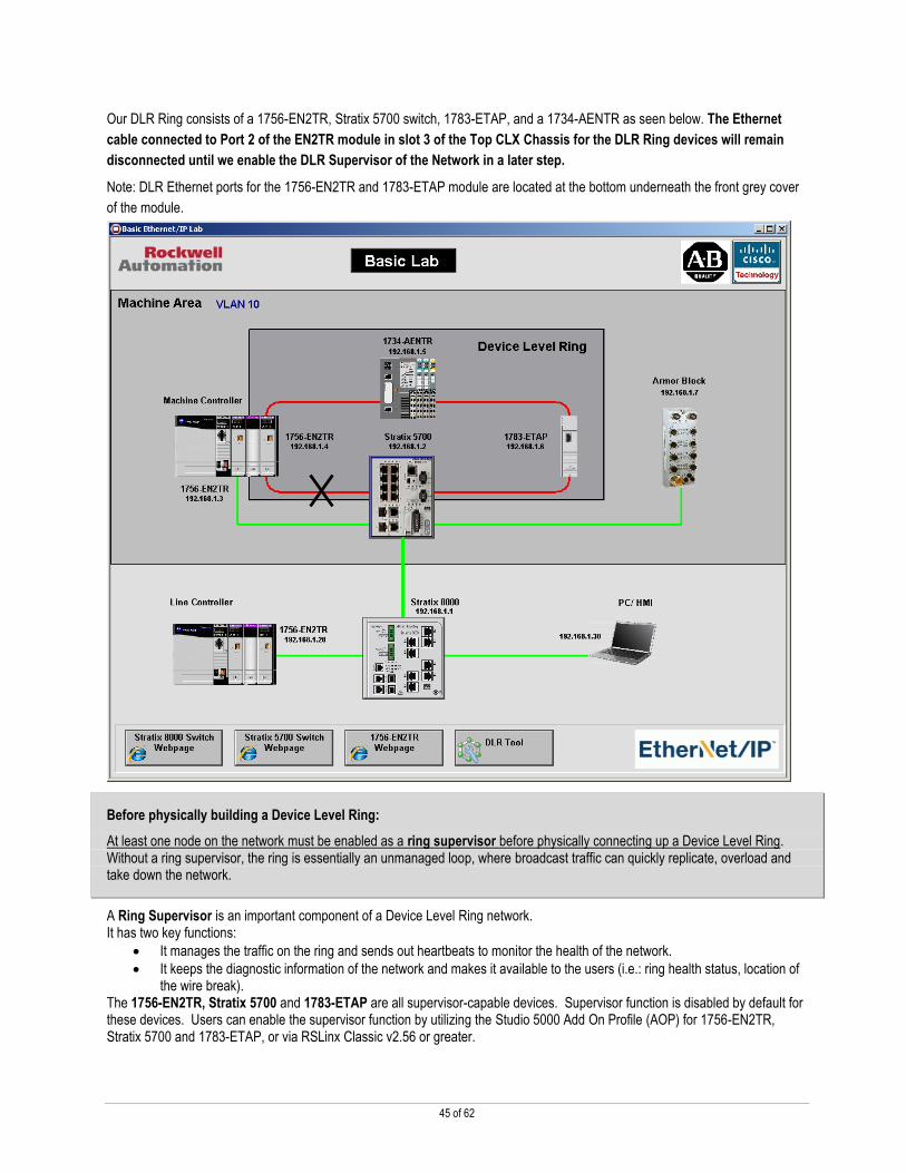
Our DLR Ring consists of a 1756-EN2TR, Stratix 5700 switch, 1783-ETAP, and a 1734-AENTR as seen below. The Ethernet
cable connected to Port 2 of the EN2TR module in slot 3 of the Top CLX Chassis for the DLR Ring devices will remain
disconnected until we enable the DLR Supervisor of the Network in a later step.
Note: DLR Ethernet ports for the 1756-EN2TR and 1783-ETAP module are located at the bottom underneath the front grey cover
of the module.
Before physically building a Device Level Ring:
At least one node on the network must be enabled as a ring supervisor before physically connecting up a Device Level Ring. Without a ring supervisor, the ring is essentially an unmanaged loop, where broadcast traffic can quickly replicate, overload and take down the network.
A Ring Supervisor is an important component of a Device Level Ring network. It has two key functions:
It manages the traffic on the ring and sends out heartbeats to monitor the health of the network.
It keeps the diagnostic information of the network and makes it available to the users (i.e.: ring health status, location of the wire break).
The 1756-EN2TR, Stratix 5700 and 1783-ETAP are all supervisor-capable devices. Supervisor function is disabled by default for these devices. Users can enable the supervisor function by utilizing the Studio 5000 Add On Profile (AOP) for 1756-EN2TR, Stratix 5700 and 1783-ETAP, or via RSLinx Classic v2.56 or greater.

46 of 62
Adding and Configuring DLR Devices to the I/O Configuration Tree
In this lab we will add the DLR devices to the I/O Configuration Tree.
To save time we already added some DLR devices to the I/O tree
Adding the Stratix 5700 to the I/O Configuration Tree.
1. Open the Logix Files folder on the desktop and double-click on the Studio 5000 project
Top_CLX_Machine_START.acd. Make sure that you selected the right file.
2. Navigate to the I/O Configuration Tree to the slot 3. Right Click on Ethernet Icon, located below the DLR_Supervisor 1756-EN2TR, and select New Module.
3. In the Search box type 1783-BMS10CGN, then highlight selection below and click Create

47 of 62
4. Type the switch name, set IP address, then click Change
5. Change Major revision to 5.
The Stratix 5700 has input and output tags. Multiple controllers can read the input tags at the same time, but only one controller can “own” the I/O and write to the output tags of the switch. Since in the Lab 2 we set the Line controller connection to the Stratix 5700 to Data connection, the Machine Controller connection here will be set to Input Data to enable read only access.
Click OK.
6. Click OK – Switch will be added to I/O configuration and close the Module Selection dialog window.
7. Download the Project to the Controller by Clicking the Processor Icon just right of the Offline word.
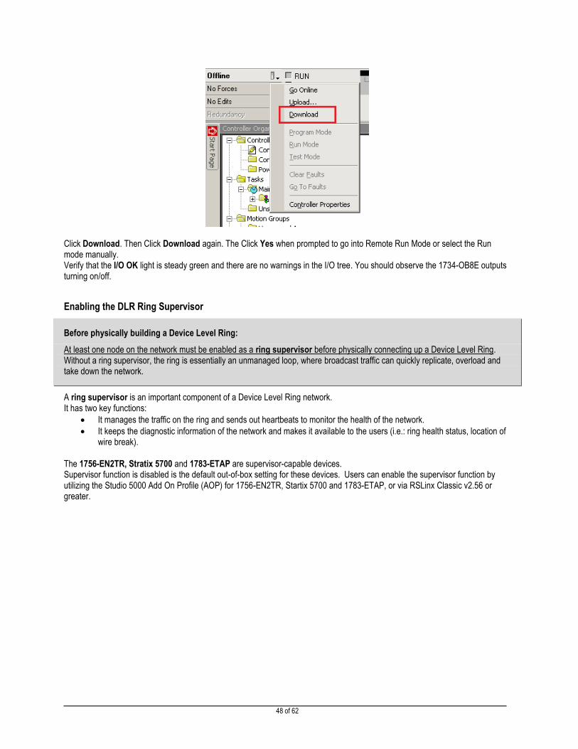
48 of 62
Click Download. Then Click Download again. The Click Yes when prompted to go into Remote Run Mode or select the Run mode manually. Verify that the I/O OK light is steady green and there are no warnings in the I/O tree. You should observe the 1734-OB8E outputs turning on/off.
Enabling the DLR Ring Supervisor
Before physically building a Device Level Ring:
At least one node on the network must be enabled as a ring supervisor before physically connecting up a Device Level Ring. Without a ring supervisor, the ring is essentially an unmanaged loop, where broadcast traffic can quickly replicate, overload and take down the network.
A ring supervisor is an important component of a Device Level Ring network. It has two key functions:
It manages the traffic on the ring and sends out heartbeats to monitor the health of the network.
It keeps the diagnostic information of the network and makes it available to the users (i.e.: ring health status, location of wire break).
The 1756-EN2TR, Stratix 5700 and 1783-ETAP are supervisor-capable devices. Supervisor function is disabled is the default out-of-box setting for these devices. Users can enable the supervisor function by utilizing the Studio 5000 Add On Profile (AOP) for 1756-EN2TR, Startix 5700 and 1783-ETAP, or via RSLinx Classic v2.56 or greater.

49 of 62
1. Referring back to the I/O Configuration Tree. Double Click the 1756-EN2TR DLR_Supervisor module in Slot 3 to enter its properties window.
2. Click on the Network Tab. If the Enable Supervisor Mode box is already checked, uncheck this box. Select Yes to the DANGER: Connection Loss Apply change dialog. You will notice that the Network Topology is registering that there is a Linear/ Star Topology and the Network Status is registering Normal. This status is an indication that the network is indeed a star/ linear topology and a Ring Supervisor has not been enabled yet.
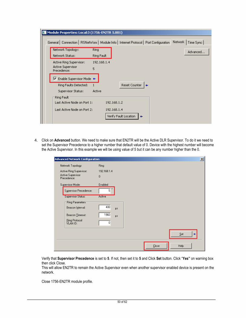
3. Check the Enable Supervisor Mode Box, and watch the status change. If the field is already selected, try unchecking it and see what happens; then re-check to continue. Now you see that the Network Topology is registering Ring and the Network Status is registering a Ring Fault. This is because we have not physically attached the final Ethernet cable that will convert this linear topology into a ring topology yet. Also the Active Ring Supervisor is IP Address 192.168.1.4 which is the 1756-EN2TR module.
50 of 62
4. Click on Advanced button. We need to make sure that EN2TR will be the Active DLR Supervisor. To do it we need to set the Supervisor Precedence to a higher number that default value of 0. Device with the highest number will become the Active Supervisor. In this example we will be using value of 5 but it can be any number higher than the 0.
Verify that Supervisor Precedence is set to 5. If not, then set it to 5 and Click Set button. Click “Yes” on warning box then click Close. This will allow EN2TR to remain the Active Supervisor even when another supervisor enabled device is present on the network. Close 1756-EN2TR module profile.

51 of 62
5. Open Stratix 5700 Module profile and select Device Level Ring (DLR) page. You can see that the Switch has Ring enabled on port Fa1/7 and Fa1/8. Also you can see that current active supervisor is at the address 192.168.1.4 (1756-EN2TR)
Attaching the Ethernet Cable to the DLR Devices
In this lab we will attach the Ethernet cable to the last DLR device in the ring.
1. Please review the Ethernet wiring diagram below.
52 of 62
2. One end of the Ethernet cable is disconnected between 1756-EN2TR and Stratix 5700 devices. Complete the
connection between the Stratix 5700 switch and the 1756-EN2TR in the Top CLX Chassis (Slot 3) port 2.
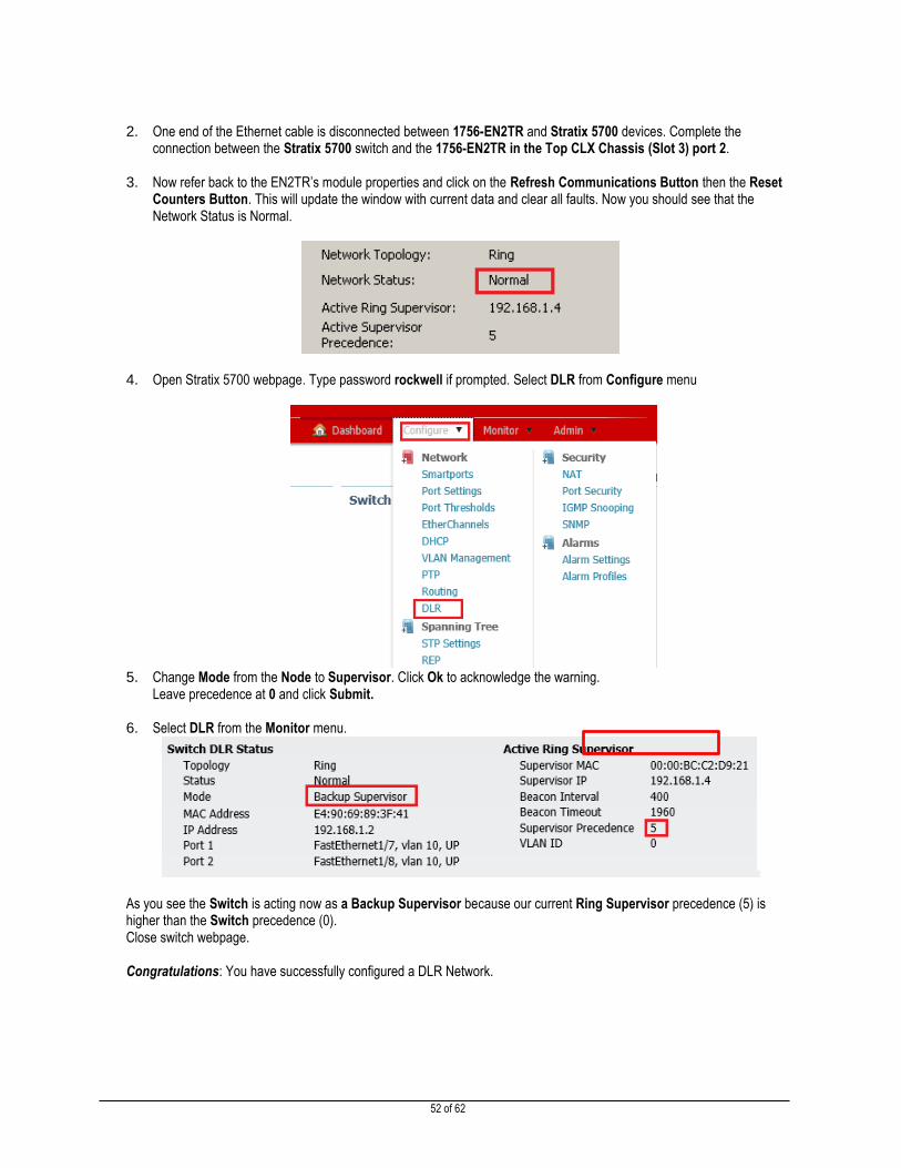
3. Now refer back to the EN2TR’s module properties and click on the Refresh Communications Button then the Reset Counters Button. This will update the window with current data and clear all faults. Now you should see that the Network Status is Normal.
4. Open Stratix 5700 webpage. Type password rockwell if prompted. Select DLR from Configure menu
5. Change Mode from the Node to Supervisor. Click Ok to acknowledge the warning.
Leave precedence at 0 and click Submit.
6. Select DLR from the Monitor menu.
As you see the Switch is acting now as a Backup Supervisor because our current Ring Supervisor precedence (5) is higher than the Switch precedence (0). Close switch webpage. Congratulations: You have successfully configured a DLR Network.
53 of 62
DLR Diagnostic Tool
This portion of the lab will review the DLR Diagnostic Tool.
Rockwell DLR Tool enables a user to visualize, diagnose and interact with Device Level Ring network.
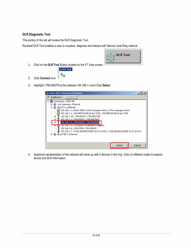
1. Click on the DLR Tool Button located on the FT View screen.
2. Click Connect Icon
3. Highlight 1756-EN2TR at the address 192.168.1.4 and Click Select
4. Graphical representation of the network will come up with 4 devices in the ring. Click on different nodes to explore device and DLR information.

54 of 62
5. Now let’s simulate a fault. Disconnect the cable at one end between the 1734-AENTR and the 1783-ETAP and watch the DLR Tool screen. You should see that there is a Ring Fault with Network Alert
6. Another advantage to using a DLR Ring over a Linear/Star Topology is that you have single fault tolerance capabilities. Take a look at the 1734-OB8E Outputs to ensure that they are still blinking. The DLR is capable of recovery time under 4 milliseconds which is fast enough not to cause an I/O connection timeout.
You can also see the DLR information on the 1756-EN2TR Webpage and/or its Module Properties Page (AOP).
7. Click on the Button located on the bottom of the FTViewSE Application.
8. Click on the Diagnostics Folder and browse to the Ring Statistics page. There you will see the same Ring Status and
Fault Data. Close Internet Explorer when you are finished reviewing.

55 of 62
9. Reconnect the cable between the ETAP and the 1734-AENTR. Confirm that the Network Status is Normal again.
This concludes the DLR the lab.

56 of 62
Lab Summary
In this lab, you have worked through exercises that demonstrated the power and flexibility of the Stratix 5700 and the Stratix 8000
Ethernet Managed Switches, and reviewed Device Level Ring operation of the embedded switch products. You have completed
the following tasks:
Stratix 5700 Layer 2 Ethernet Managed Switch
Configured a Stratix 5700 Managed Switch
Reviewed the switches GUI and module-defined tags
Configured the Switches AOI and reviewed its FTViewSE Faceplate
Review of the Switches Web Device Management Interface.
Stratix 8000 Ethernet Managed Switch (optional tasks)
Reviewed the configuration of the Stratix 8000 Ethernet Managed Switch
Reviewed the switches GUI and module-defined tags
Reviewed the Switches AOI and its FTViewSE Faceplate
Review of the switches Web Device Management Interface
Studio 5000 Logix Designer Software
Configured Rockwell Automation EIP devices in a Linear and DLR Network Topologies.
By completing these tasks, you have experienced some of the enabling technologies that make the Integrated Architecture and
the Stratix Ethernet Managed Switch a superior control system:
FactoryTalk
Logix

57 of 62
Instructor’s Use Only: Lab Configuration and Setup
Guide
Lab Configuration Information
Lab Information
Lab Name Applying Basic EtherNet/IP Features in Converged Plant-wide Ethernet Architectures.
Lab Description
This hands-on lab will cover a variety of techniques, best practices, software and products using EtherNet/IP. This lab will provide Stratix 5700 and Stratix 8000 hardware familiarization. Configuring the Stratix 5700 and Stratix 8000 using Device Manager, the AOP and controller tags in Studio 5000. Using Stratix FactoryTalk View faceplates for diagnostics. Device Level Ring Topology configuration.
Lab Created by Eduard Polyakov – Sr. Commercial Engineer
Date Created 12/1/2014
Last Updated by Arkady Nabutovsky – Sr. Commercial Engineer
Date Updated 9/4/2015
Hardware Configuration
Qty Demo Cat.# / Description Slot IP Address Firmware
1 ENET-21 Demo Box
Top CLX Chassis
1756-L75 Slot 0 V26.013
1756-EN2TR Slot 1 192.168.1.3 V5.008
1756-IB16ISOE Slot 2 V2.009
1756-EN2TR Slot 3 192.168.1.4 V5.008
Bottom CLX Chassis
1756-L75 Slot 0 V26.013
1756-EN2TR Slot 1 192.168.1.20 (DHCP) V5.008
1756-IB16ISOE Slot 2 V2.009
1756-SFM Slot 3 N/A
Stratix 5700 Ethernet Switch N/A 192.168.1.2 V15.2(3)EA1
Stratix 8000 Ethernet Switch N/A 192.168.1.1 V15.2(3)EA1
1783-ETAP 192.168.1.6 V2.002
1734-AENTR Slot 0 192.168.1.5 V3.012
1734-IB8 Slot 1 V3.022
1734-OB8E Slot 2 V3.022
1734-OE2V Slot 3 V3.005
1732E-IB16M12SOEDR 192.168.1.7 V1.007

58 of 62
Computer/Host Settings
Location Files
Computer Name Core
IP Address 192.168.1.30
Operating System Windows 7 with Internet Explorer V9, V10, V11 or Mozilla V26, V27 installed
Application Versions
Vendor Software Version Service Pack
RA Studio 5000 V26.01
RA RSLinx V3.73
RA FTViewSE V8
Photograph of Hardware:
This hands-on lab uses the ENET21 Demo Box. This system is comprised of 2 Control Logix controllers, 2 different types of
Stratix Ethernet Switches, 1 Point I/O module, 1 Armor Block module, 3 different styles of Ethernet modules, and 1 Computer.
Note: The same demo box is used for this lab and the Advanced EtherNet/IP lab. The switch configuration and cabling for some of the devices is different between the labs. Please make sure that correct reset steps are followed since the box may be configured for a different lab.

59 of 62
Lab Resetting and Startup Procedures
This section describes how to reset the hardware and verify configuration when setting up the lab and between the sessions.
Please read all steps through one time before hooking and starting up the lab.
1. Wire up all Ethernet devices to the corresponding Ethernet ports on the Stratix 8000 and 5700 switches as seen below.
Note that the Line Controller (connected to the Stratix 8000) is in the bottom chassis of the demo box. The
Machine Controller (connected to the Stratix 5700 and DLR) is in the top chassis.
a. Important: Please do not connect the cable to the “Machine” EN2TR Slot 3, Port 2 (Top CLX). This will
be done in the Lab 4 (DLR).
b. Make sure that “Line” EN2TR Slot 1 Port 1 (Bottom CLX) is connected to the Stratix 8000 Fa1/5. This is
necessary for the correct IP address assignment.
c. Verify the cabling for other devices according to the diagram. Note that these connections will not change
during the normal lab steps.
2. Restart the Basic EtherNet/IP lab image on the PC. The IP address of the VM is set to 192.168.1.30.

60 of 62
When the lab image is restarted, a script is running to restore switch configurations. Please follow the steps below to make sure that it executes correctly.
3. You should see the message on the screen. Connect the PC Ethernet cable to the Stratix 8000 port Fa1/1 (if this is not
done already). Click OK to continue.
4. The script verifies connectivity to the switch and if the TFTP server is running, then copies the correct configuration to
the Stratix 8000 switch. DO NOT close or click on any open windows.
5. Wait until you see the next message on the screen. Connect the PC Ethernet cable to the Stratix 5700 port Fa1/1. This
is a temporary connection to restore the Stratix 5700 switch configuration. Click OK to continue.
6. The script verifies connectivity to the switch and if the TFTP server is running, then copies the correct configuration to
the Stratix 5700 switch. DO NOT close or click on any open windows.
7. Move the PC Ethernet cable back to the Stratix 8000 port Fa1/1. This completes the cabling for the lab according
to the diagram.
8. Verify IP address assignment for the EN2TR modules via the LED display and in the RSLinx Classic. Cycle demo box
power if addresses are not correct.
a. “Machine” EN2TR slot 1 (Top CLX) - 192.168.1.3 (Static IP mode)
b. “Machine” EN2TR slot 3 (Top CLX) - 192.168.1.4 (Static IP mode)
c. “Line” EN2TR slot 1 (Bottom CLX) – 192.168.1.20 (DHCP/BOOTP mode)
9. Make sure that DLR Supervisor mode is disabled on EN2TR modules 192.168.1.3 and 192.168.1.20
10. Make sure that the cable to the “Machine” EN2TR Slot 3, Port 2 (Top CLX) is disconnected.
The DLR Supervisor mode may be enabled or disabled on the “Machine” EN2TR slot 3 (Top CLX) with IP address 192.168.1.4. Users will be changing the mode during the lab.
11. Review the list of known issues and troubleshooting steps on the next page before conducting the lab.
It is recommended to run through the lab on all stations before the event starts.

61 of 62
Lab Troubleshooting
Some of the issues that may happen during the lab and during the reset are listed here.
Possible Issues During the Lab
Problem Troubleshooting Steps
Faceplate for the Stratix switch comes up with a red banner stating communication issues
Change the key switch for the Line Controller (Bottom CLX) from Run – Program – Run. This should clear the MSG fault and usually occurs only once.
Faceplate for the DLR comes up with a red banner stating communication issues
Change the key switch for the Machine Controller (Top CLX) from Run – Program – Run. This should clear the MSG fault and usually occur only once.
“Invalid Password” message when trying Broken Wire Test in the switch faceplate
Make sure that users hit Enter after typing the password, and then click Login.
“Unsupported device” message in the Device Manager Dashboard
Clear IE cache, restart the browser
FactoryTalk Security logon prompt when opening Studio 5000
Try the following steps: 1. Open FactoryTalk Directory Configuration Wizard (Start – Rockwell
Software – FactoryTalk Tools). 2. Select both Network and Local directories as options. 3. Configure directories using username labuser and password rockwell
as the local Windows administrator.
Possible Issues When Resetting the Lab
Problem Troubleshooting Steps
Cannot login to the switch via the CNA or webpage using rockwell password.
Try to enter username admin and password rockwell. The issue may be that the switch has been updated with the new firmware and the Express Setup procedure applied. The latest firmware requires a username for the Express Setup. After the correct lab configuration is restored with the CNA, only password is required.
Cannot restore configurations using the CNA. Restore process fails.
Verify that Windows firewall is disabled. Verify that Symantec or other antivirus software is not running on the PC. It seems like Symantec software on the computers with a standard RA image requires connection to the corporate network to allow TFTP or FTP connections. There should be no issues with the event PCs.
Cannot connect to the Stratix 8000 switch after the demo box was used in the Advanced EIP lab.
Try to connect using 10.10.10.30 address and Stratix 8000 Fa1/2 port. This should NOT apply when resetting between the Basic EIP sessions.

62 of 62
Cannot connect to the switch via the CNA or the webpage using the normal steps. Cannot ping 192.168.1.x address of the switch from the PC.
Try the following steps to resolve the issue: 1. Make sure that direct connection is made to the switch through the
correct port (Fa1/1). 2. Verify the IP address of the PC (192.168.1.30). 3. Reset the demo box. 4. Reboot the PC (physical machine, not VM). 5. In case if the switch configuration has been altered (wrong IP address,
wrong VLAN on the port etc.), the switch needs to be reset to the factory default configuration and the correct IP address should be assigned. This can be done using the Express Setup button. Please refer to the product manual.
6. Serial console connection and CLI can also be used to correct the configuration (requires knowledge of IOS commands).
7. After the switch has been reset to the factory default configuration and correct IP address has been assigned, use the CNA to restore the lab configuration.
Duplicate IP Address error in one of the EN2TR modules
Try the following steps to resolve the issue: 1. Check the IP address of the physical NIC of the PC (not the VM). Make
sure that it has NOT been assigned in the 192.168.1.1 – 192.168.1.7 range, or .20, .30. If the PC’s NIC is set to DHCP and keeps getting the overlapping address, do the following in the command prompt: ipconfig /release net stop dhcp net start dhcp ipconfig /renew
2. Verify settings for other devices. 3. Reset the EN2TR module. 4. Reboot the 8000 switch (power down the demo box). 5. Restore the switch configuration from CNA helped.
Publication XXXX-XX###X-EN-P — Month Year Copyright© 2013 Rockwell Automation, Inc. All rights reserved.
Supersedes Publication XXXX-XX###X-EN-P — Month Year