Basic Electrical Controls for Fluid Power Circuits.ppt
69
Basic Electrical Controls for Fluid Power Circuits Electro-pneumatics Electro-hydraulics
-
Upload
loveincyber3 -
Category
Documents
-
view
272 -
download
25
Transcript of Basic Electrical Controls for Fluid Power Circuits.ppt

Basic Electrical Controls for Fluid Power Circuits
Electro-pneumaticsElectro-hydraulics

Introduction
Why do we have to use it ?• More machines are designed using electrical
signals from computer• Soft-wired rather than hard-wired systems• Simpler systems than pure pneumatic or
hydraulic systems• Development for advanced systems are more
achievable using this systems

Power in hydraulic systems

Calculation of input and output power

Diagrammatic representation of the structure of a hydraulic system

Hydraulic system and its components name

Signal Flow in Control System
• Controller can be divided into signal input, signal processing, signal output and command execution
• The mutual influence can be shown using signal flow diagram

Schematic layout of an electro-hydraulic installation

Hydraulic systems and its control system

Signal flow and components of a hydraulic control system

Signal flow and components of an electro-hydraulic control system

Electro-hydraulics System
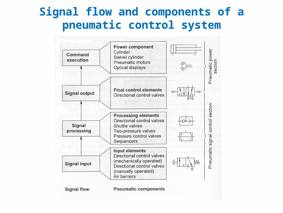
Signal flow and components of a pneumatic control system

Signal flow and components of an electro-pneumatic control system
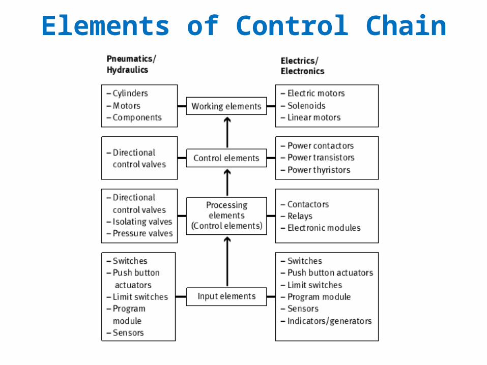
Elements of Control Chain

Structure of an electro-pneumatic controller

Signal control section of relay control system

Signal control section with PLC

Power supply
• Connection to mains supply• Supplies signal control
section with specified or maximum voltage and current values includes.
– Voltage transformation – Rectification – Stabilization – Fuse protection• In mobile hydraulic
systems, rechargeable battery systems or generators are used as a power supply for the signal control section.

Switching Contacts and Types of Actuation

Types of Actuation of Switching Elements

Switching Symbols for Solenoid Coils and Relays

Electrical power supply unit

SensorHave the task of measuring information and passing this on to the signal processing partFungsi dari sensor :1.Detect the advanced and retracted end position of the piston rod in cylinder drives2.Detect keberadaan dan posisi benda3.Measure and monitor pressure

Jenis – Jenis Sensor1. Limit Switch (Mechanically Actuated)2. Proximity Switch (Non-contact switching)
or contactless switch- Reed switch- Inductive proximity switch- Capacitive proximity switch- Optical proximity switch
3. Pressure Sensor

Reed SwitchReed switches are magnetically-actuated proximity sensors. They consist of
two contact blades in a small glass tube filled with protective gas. The action of a magnet causes the contact between the two blades to close so that an
electrical current can flow

Inductive proximity switchInductive proximity sensors consist of an electrical resonant circuit (1), a flip-flop (2) and an amplifier (3). When voltage is applied to the connections, the resonant circuit generates a (high-frequency) magnetic alternating field that escapes from the front side of the sensor. Inductive proximity sensors can be
used to detect all materials with good electrical conductivity, for example graphite as well as metals.

Capacitive proximity switchCapacitive proximity sensors not only respond to materials with a
high electrical conductivity (e.g. metals), but also to all insulators with a high dielectric constant (e.g. plastics,
glass, ceramic, liquids and wood).

Optical Proximity SwitchOptical proximity sensors always have a
transmitter and a receiver. They use optical (red or infrared light) and electronic components and
modules to detect an object located between the transmitter and receiver
A distinction is made between three types of optical proximity sensor: • through-beam sensors, • retro-reflective sensors,
• diffuse sensors.

Through-Beam SensorsIf an object, workpiece or even a person enters the path between the transmitter and receiver, the light beam is interrupted and a signal is triggered that initiates a switching operation at the output (ON/OFF).

Retro-Reflective Sensor If an object, workpiece or even a person enters the path between the transmitter and reflector, the light beam is
interrupted and a signal triggered that initiates a switching operation at the output (ON/OFF).

Diffuse SensorsThis operational principle means diffuse sensors can only be
used if the workpiece or machine part to be detected is highly reflective (e.g. metallic surfaces, light colours)

Pressure SensorIn a mechanical pressure switch, the pressure acts on
a piston area. If the force exerted by the pressure exceeds the spring force, the piston moves and actuates the contacts of the switching elements

Push Button Switch (Manually – Actuated)
• Normally open contact • Normally closed contact

Push button switch and Limit switch (Mechanically – Actuated)
• Changeover contact
• Limit switch

Basic Electrical Devices
• Limit switch • Pressure switch

Basic Electrical Devices
• Temperature switch • Temperatures switch symbol

Basic Electrical Devices
• Push button symbol • Limit switch symbol

Solenoid

Basic Electrical Devices
• Solenoid and lamp indicator symbol
• Timer switch symbol

Relay (Electrically – Actuated) and Its Symbol

Relay dan Contactor
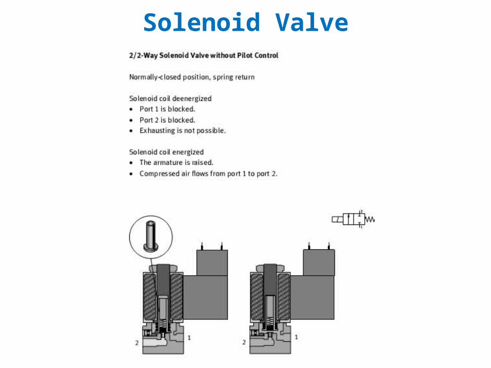
Solenoid Valve

Solenoid Valve with Pilot Control

3/2 Way-Solenoid Valve

5/2 Way-Solenoid Valve

Direct and Indirect Control Using Relays

Controlling a Double-Acting Cylinder

Parallel connection (OR operation)
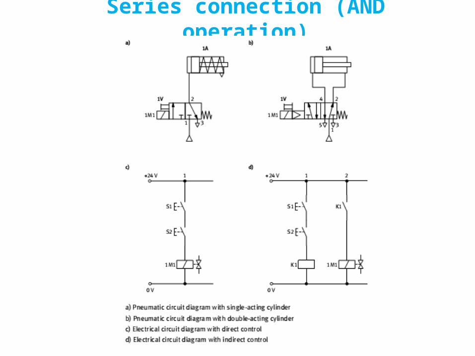
Series connection (AND operation)

Signal storage by means of a relay circuit with self-latching loop

Manual forward and return stroke control using relays with self-latching loop

Signal storage by means of a double solenoid valve

Automatic return stroke control using double solenoid valves

Controlling a cylinder via timing

Control of hydraulic cylinder using single limit switch
• Hydraulic and electrical circuit

Reciprocation of cylinder using pressure switch

Reciprocation of cylinder using limit switches
• Hydraulic and electrical circuit

Dual cylinder sequencing circuit
• Hydraulic and electrical circuit

Second dual cylinder sequencing circuit• Hydraulic and electrical circuit

Electro-pneumatic box – sorting system• Hydraulic and electrical circuit

Electrical control of regenerative circuit• Hydraulic and electrical circuit

Counting, timing and reciprocation of a hydraulic cylinder• Hydraulic and electrical circuit

Open and Closed Loop Control
x y
Process
ProcessController
x y

Tractor using electro-hydraulic servo system
• Schema and its component

Electro-hydraulic servo system
• System components

Servo valve• Components of servo valve

Closed – loop system
• Block diagram of an electro-hydraulic servo system

Electro-hydraulic positional closed – loop system
• System Block diagram