BASIC CONCEPTS - UNSJ
29
BASIC CONCEPTS SIMULATION MODEL DELTA TIME - CONCURRENCY
Transcript of BASIC CONCEPTS - UNSJ

BASIC CONCEPTS
SIMULATION MODEL
DELTA TIME - CONCURRENCY

VHDL Simulation Model
VHDL was designed as a simulation language, so to understand the language we must examine the behavior of a VHDL simulator
The basis of VHDL simulation is event processing
All VHDL simulators are event-driven simulators
There are three essential concepts to event-driven simulation:
Simulation time
Delta time
Event processing
DSDA 2C Sisterna

VHDL Simulation – Simulation Time
Simulation Time
During a simulation a simulator keeps track of the current time that has been simulated, that is, the circuit time that has been modeled by the simulator, not the time the simulation has actually taken
This time is know as simulation time. It is usually measured as an integral multiple of a basic unit of time known as resolution limit. The simulator can not measure time delays less than the resolution limit
For gate level simulation the resolution limit may be quite fine, possibly down to 1ps
For RTL level simulation, it is only important a clock-cycle by clock-cycle behavior and the transfer functions are described with zero o unit time delay
DSDA 3C Sisterna

VHDL Simulation – Event
DSDA
Event
– It is a change in a signal (I/O ports are signals too). When a
change happens on a signal, an event is posted in an event
queue for the simulation time at which the change occurs
– When the simulator processes that event, it does so by
recalculating any statements which have that signal as an
input (statements ‘sensitive’ to that signal). This results in
changes to other signals and therefore more events are
generated
4C Sisterna

VHDL Simulation – Delta Time
Delta time
z <= a and b after 5 ns;
z <= a and b;
If a change happens on a or on b, the statement is revaluated
Z has to be updated at the same time as the signal from which it is generated. Delta Time (δ) VHDL concept
The event for z is scheduled for the next delta time of the current simulation time
DSDA 5C Sisterna

VHDL Simulation – Delta Time
Delta time
All the events at the current delta time are processed as a batch, resulting in a new set of events, some of which may be scheduled for the current simulation time, which means they are scheduled for the next delta time
The next delta time events are then themselves processed as a batch, resulting in further events and so on until there are no more events at the current simulation time. Then the simulation time moved on
DSDA 6C Sisterna

VHDL Simulation – Delta Time
Delta time
A delta time has no equivalent in real time. It is executed while the simulation clock is standing still
In a signal assignment the value is not assigned to the signal directly, but after a delta delay at the earliest
b <= a;-- signal b gets the value
-- of signal a after one delta time
Variables are updated immediately, that is, before any delta time in which the assignment is executed. There is no concept of delta delay for variable
q := not q;
DSDA 7C Sisterna

Delta Time – Example 1
-- delta delay example 1
entity fulll_addder is
port (a, b, c: in std_logic;
sum, cout: out std_logic);
end full_adder;
architecture behavioral of full_adder is
signal sum1, sum2, c1, c2: std_logic;
begin
sum1 <= a xor b;
c1 <= a and b;
sum2 <= sum1 xor c;
c2 <= sum1 and c;
sum <= sum2;
cout <= c1 or c2;
end behavioral;
DSDA 8C Sisterna

Delta Time - Example 1
DSDA
– It is assumed that the circuit is initially stable with all the inputs set
to 0
– Then all the internal signals and the outputs will be 0. these values
are assigned during the initialization or elaboration phase of the
simulation, which happens at time zero
– Consider:
– Input b changes from 0 to 1 at simulation time of 20ns
– An event is generated for signal b and the event is scheduled at
the first delta time of the 20 ns simulation time
– The event on b is processed causing an evaluation of the
statements where b is on the RHS (right hand side). These are:sum1 <= a xor b;
c1 <= a and b;
– As a result of the recalculation, events are scheduled for sum1 and
c1 at the current simulation time, 20ns, but at the next delta time.
Neither signal has changed value yet.
9C Sisterna

Delta Time - Example 1
DSDA
20 ns 20 ns + delta 20 ns+2delta 20ns+3 delta 20ns+4 delta
a 0 0 0 0 0
b 0 1 1 1 1
c 0 0 0 0 0
sum1 0 0 1 1 1
sum2 0 0 0 1 1
sum 0 0 0 0 1
c1 0 0 0 0 0
c2 0 0 0 0 0
cout 0 0 0 0 0
Event queue b → 1 sum1 → 1
c1 → 0
sum2 → 1
c2 → 0
sum → 1
cout → 0
10C Sisterna

Delta Time – Example 2
-- delta delay example 1
entity aoi is
port(
A, B, C, D: in std_logic;
E: out std_logic);
end aoi;
DSDA
O2
O1 O3
11C Sisterna

Delta Time - Example 2-1
--=========================================--
architecture dflow of aoi is
begin
E <= not ((A and B) or (C and D)); -- CS1
end dflow;
DSDA 12C Sisterna

Delta Time - Example 2
DSDA
CS1
Delta 1
Delta 2
Delta Time steps for dflow architecture
13C Sisterna

Delta Time - Example 2-2
--=================================--
architecture dflow1 of aoi is
signal O1, O2, O3: std_logic;
begin
E <= not O3; -- CS1
O1 <= A and B; -- CS2
O3 <= O1 or O2; -- CS3
O2 <= C and D; -- CS4
end dflow1;
DSDA
O2
O1 O3
14C Sisterna

Delta Time - Example 2-2
DSDA
Delta Time steps for dflow1 architecture
Delta 2
Delta 1
15C Sisterna

Delta Time - Example 2-3
--====================================--
architecture behav2 of aoi is
begin
process(A, B, C, D)
variable O1, O2, O3: std_logic;
begin
O1 := A and B; -- SS1
O2 := C and D; -- SS2
O3 := O1 or O2; -- SS3
E <= not O3; -- SS4
end process;
end behav2;
O2
O1 O3
16DSDAC Sisterna

Delta Time - Example 2-3
DSDA
Delta Time steps for behav2 architecture
SS1
Delta 2
Process P1SS2
SS3
SS4
Delta 1
17C Sisterna

Delta Time - Example 2-4
--====================================--
architecture behav2_bad of aoi is
begin
process(A, B, C, D)
variable O1, O2, O3: std_logic;
begin
O3 := O1 or O2;
O1 := A and B;
O2 := C and D;
E <= not O3;
end process;
end behav2_bad;
DSDA 18C Sisterna

Delta Time - Example 2-5
architecture behav3 of aoi is
signal O1, O2, O3: std_logic;
begin
O1 <= A and B; -- CS1
O2 <= C and D; -- CS2
P2: process( O3) -- CS4
begin
E <= not O3; -- SS1
end process P2;
P1: process (O1, O2)-- CS3
begin
O3 <= O1 or O2; -- SS1
end process P1;
end behav3;
DSDA
O2
O1 O3
19C Sisterna

Delta Time - Example 2-5
DSDA
CS2
Delta 1
Delta 2
Time steps for behav3 architecture
CS1
CS3
CS4
Delta 3
and functionality
inverter
functionality
Process P2
or functionality
Process P1
20C Sisterna

21
Delta Time - Example 2-6
--===============================--
architecture behav4 of aoi is
signal O1, O2, O3: std_logic;
begin
process(A, B, C, D)
begin
O1 <= A and B;
O2 <= C and D;
O3 <= O1 or O2;
E <= not O3;
end process;
end behav4;
DSDAC Sisterna
O2
O1 O3

Delta Time - Example 2-7
--====================================--
architecture behav4_right of aoi is
signal O1, O2, O3: std_logic;
begin
process(A, B, C, D, O1, O2, O3)
begin
O1 <= A and B;
O2 <= C and D;
O3 <= O1 or O2;
E <= not O3;
end process;
end behav4_right;
DSDAC Sisterna 22
O2
O1 O3
DSDA 23
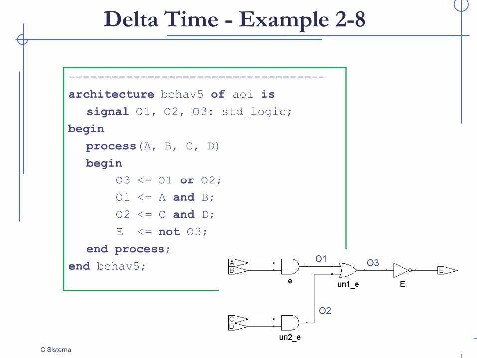
Delta Time - Example 2-8
--================================--
architecture behav5 of aoi is
signal O1, O2, O3: std_logic;
begin
process(A, B, C, D)
begin
O3 <= O1 or O2;
O1 <= A and B;
O2 <= C and D;
E <= not O3;
end process;
end behav5;
O2
O1 O3
C Sisterna

Delta Time - Example 2-8
DSDA
Initialization 5 ns … 10 ns 20 ns
A 0 0 0 1
B 0 0 1 1
C 1 1 1 1
D 0 1 1 1
E
O1
O2
O3
24C Sisterna

DSDA 25
Delta Time - Example 2-9
C Sisterna
library ieee;
use eee.std_logic_1164.all;
entity aoi is
port(A, B, C, D: in std_logic;
E: out std_logic);
end aoi;
architecture dflow1 of aoi is
signal O1, O2, O3:std_logic;
begin
E <= not O3; -- CS1
O1 <= A and B; -- CS2
O2 <= C and D; -- CS3
O3 <= O1 or O2; -- CS4
end dflow1;

DSDA 26
Delta Time - Example 2-10
C Sisterna

DSDA 27
Delta Time - Example 2-10
O2
O1 O3
C Sisterna

Delta Time – Example 3
DSDA
--
-- delta delay example 3
--
entity example_3 is
port(a, b, c, d, e, f: in std_logic;
y1, y2: out std_logic);
end entity example_3;
architecture data_flox of example_3 is
signal sig1, sig2: std_logic;
begin
sig1<= a and b and c;
process (d, sig1, sig2)
begin
y1 <= not sig2;
sig2 <= sig1 and d;
end process;
y2 <= not e;
end data_flow;
28C Sisterna

Delta Time – Example 3
DSDA
Delta delay
a or b or c change
e or f
change
y2 assignedy2 scheduled
y1 assigned
y1 scheduled
s2 assigned
d change
process triggered
s2 scheduled
s1 scheduled
process triggered
s1 assigned
s2 assigned
y1 scheduled
y1 assigned
s2 scheduled
C Sisterna 29