
BASEPLATE KIT INSTALLATION INSTRUCTIONS ... … · Special Tools Needed Cut off wheel or die...
6
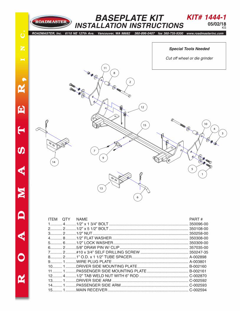
KIT# 1444-1 05/02/18 KS ITEM QTY NAME PART # 1........... 4 ..........1/2” x 1 3/4” BOLT ......................................................................... 350096-00 2........... 2 ..........1/2” x 5 1/2” BOLT ......................................................................... 350108-00 3........... 2 ..........1/2” NUT ........................................................................................ 350258-00 4........... 8 ..........1/2” FLAT WASHER ...................................................................... 350308-00 5........... 6 ..........1/2” LOCK WASHER ..................................................................... 350309-00 6........... 2 ..........5/8” DRAW PIN W/ CLIP ............................................................... 357035-00 7........... 2 ..........#10 x 3/4” SELF DRILLING SCREW ............................................ 350247-35 8........... 2 ..........1” O.D. x 1 1/2” TUBE SPACER.................................................... A-002898 9........... 1 ..........WIRE PLUG PLATE ...................................................................... A-003801 10......... 1 ..........DRIVER SIDE MOUNTING PLATE............................................... B-002160 11 ......... 1 ..........PASSENGER SIDE MOUNTING PLATE ...................................... B-002161 12......... 4 ..........1/2” TAB WELD NUT WITH 6” ROD ............................................. C-002870 13......... 1 ..........DRIVER SIDE ARM ...................................................................... C-002592 14......... 1 ..........PASSENGER SIDE ARM .............................................................. C-002593 15......... 1 ..........MAIN RECEIVER .......................................................................... C-002594 1 5 6 12 13 14 15 7 9 3 4 10 2 8 11 R O A D M A S T E R , I N C. ROADMASTER, Inc. 6110 NE 127th Ave. Vancouver, WA 98682 360-896-0407 fax 360-735-9300 www.roadmasterinc.com BASEPLATE KIT INSTALLATION INSTRUCTIONS Special Tools Needed Cut off wheel or die grinder
Transcript of BASEPLATE KIT INSTALLATION INSTRUCTIONS ... … · Special Tools Needed Cut off wheel or die...
KIT# 1444-105/02/18
KS
ITEM QTY NAME PART #1........... 4 ..........1/2” x 1 3/4” BOLT ......................................................................... 350096-002........... 2 ..........1/2” x 5 1/2” BOLT ......................................................................... 350108-003........... 2 ..........1/2” NUT ........................................................................................ 350258-004........... 8 ..........1/2” FLAT WASHER ...................................................................... 350308-005........... 6 ..........1/2” LOCK WASHER ..................................................................... 350309-006........... 2 ..........5/8” DRAW PIN W/ CLIP ............................................................... 357035-007........... 2 ..........#10 x 3/4” SELF DRILLING SCREW ............................................ 350247-358........... 2 ..........1” O.D. x 1 1/2” TUBE SPACER .................................................... A-0028989........... 1 ..........WIRE PLUG PLATE ...................................................................... A-00380110......... 1 ..........DRIVER SIDE MOUNTING PLATE ............................................... B-00216011 ......... 1 ..........PASSENGER SIDE MOUNTING PLATE ...................................... B-00216112......... 4 ..........1/2” TAB WELD NUT WITH 6” ROD ............................................. C-00287013......... 1 ..........DRIVER SIDE ARM ...................................................................... C-00259214......... 1 ..........PASSENGER SIDE ARM .............................................................. C-00259315......... 1 ..........MAIN RECEIVER .......................................................................... C-002594
1
5
6
12
13
14
15
7
9
34
10
2
8
11
R
O
A
D
M
A
S
T
E
R,
I
N
C.
ROADMASTER, Inc. 6110 NE 127th Ave. Vancouver, WA 98682 360-896-0407 fax 360-735-9300 www.roadmasterinc.com
BASEPLATE KIT INSTALLATION INSTRUCTIONS
Special Tools Needed
Cut off wheel or die grinder

KIT# 1444-105/02/18
KS
Fig.A
Fig.B
This is one of our crossbar-style series, which allows the visible front portion of the baseplate to be easily removed from the
front of the vehicle (Fig.A and Fig.B). This kit consists of a main receiver brace, two removable front braces, and a hardware pack. The main receiver brace mounts to the sub-frame and the two removable front braces fit into the main receiver brace. Before starting the installation, lay out the kit components in order, as they will be used. This will give you a visual idea of how the components work, and will also confirm that everything is pres-ent and accounted for.
IMPORTANT: All baseplates must be assembled with all the bolts left loose for final adjustment and positioning (before tightening) unless otherwise instructed. All bolts must be torqued for proper strength. If more than one bolt is used per fastening point, the diagram may only show one.
• Use flat washers over all slotted holes • Use lock washers on all fasteners
• Installation of most baseplates requires moderate mechanical ap-titude and skills. We strongly recommend professional installation by an experienced installer.
• The installer must read the instructions and use all bolts and parts supplied. Failure to do so could result in loss of the towed vehicle.
• Use Loctite® Red on all bolts used for mounting this bracket.
• Every 3,000 miles, the owner must inspect the fasteners for proper torque, according to the bolt torque requirements chart on the last page of these instructions. The owner must also inspect all mount-ing points for cracks or other signs of fatigue every 3,000 miles. Failure to do so could result in loss of the towed vehicle.
• The owner must check the vehicle manufacturer's instructions for the proper procedure(s) to prepare the vehicle for towing. Some vehicles must be equipped with a transmission lube pump, an axle disconnect, driveline disconnect or free-wheeling hubs before they can be towed. Failure to properly equip the vehicle will cause severe damage to the transmission.
• If running changes were made by the vehicle manufacturer after this kit was designed, some bolts or other fasteners in the hardware pack may no longer be the correct size. It is the installer’s responsibility to verify that the baseplate is securely fastened to the vehicle and fit-ted with the correct hardware to account for these changes. Failure to securely fasten the baseplate could result in loss of the towed vehicle.
• If the towed vehicle has been in an accident, it must be properly re-paired before attaching the baseplate. Do not install the baseplate if any structural frame damage is found. Failure to repair the damage could result in the loss of the towed vehicle.
ROADMASTER Limited Warranty, including One-Year Conditional Warranty Text and Product Registration Card, in Carton.
• Roadmaster manufactures many styles of baseplates. If your base-plate has removable arms, they must be removed before driving the vehicle, unless the arms can be pinned or padlocked in place. If not secured, the arms could vibrate out, resulting in non-warranty damage or personal injury.
• Some motorhome chassis have such a tight turning radius that you can damage your motorhome, towed vehicle, tow bar or baseplate while turn-ing sharply. Before getting on the road, test your turning radius in an empty parking lot. Turning too sharply could result in non-warranty damage to towing system, motorhome and/or towed vehicle.
• Do not back up with the towed vehicle attached or non-warranty damage will occur to your towing system, motorhome and/or towed vehicle.
• The safety cables must connect the towing vehicle to the towed vehicle frame to frame, with the cables crossed, with enough slack for sharp turns. Refer to the cable instructions for proper routing. Failure to leave enough slack in the safety cables, or failure to connect the safety cables frame to frame, will result in the loss of the towed vehicle.
• This kit is designed for use with ROADMASTER tow bars and ROAD-MASTER adaptors only. Using this kit with other brands, without an approved ROADMASTER adaptor, may result in non-warranty damage or injury.
• Do not use this document for custom fabrication, as it may not show all parts or structural components. Custom fabrication, or any attempt to copy this baseplate design, could result in loss of the towed vehicle.
• Upon final installation, the installer must inspect the baseplate to ensure adequate clearance, particularly around hoses, air condi-tioner lines, radiators, etc., or non-warranty damage to the towed vehicle will result.
• This baseplate is only warranteed for the original installation. In-stalling a used baseplate on another vehicle is not recommended and will void the warranty.
Failure to follow these instructions can result in property damage, personal injury or even death.WARNING
BASEPLATE KIT INSTALLATION INSTRUCTIONS
ROADMASTER, Inc. 6110 NE 127th Ave. Vancouver, WA 98682 360-896-0407 fax 360-735-9300 www.roadmasterinc.com

KIT# 1444-105/02/18
KS
1. Important: please use all supplied bolts and parts and read all instructions carefully before beginning this installation. The majority of questions you may have can be answered within the text, and proper installation will ensure safe and secure travel. Now, begin the installation.
Note: it is necessary to compare bumpers to figure out whether or not trimming is required. If you have a Hard Rock bumper as shown in Figures A and B: trim the skid plate as shown in Figures C and D. Using tape or a marker, indicate the front corners of the skid plate for trimming, in a line parallel with the back of the subframe (Fig.C). Measure over 2¾" from the edge of the skid plate and mark, leaving enough material for the mounting tab (Fig.D).
Fig.C Fig.D
Fig.E
Fig.G
BASEPLATE KIT INSTALLATION INSTRUCTIONS
ROADMASTER, Inc. 6110 NE 127th Ave. Vancouver, WA 98682 360-896-0407 fax 360-735-9300 www.roadmasterinc.com
mounting tab
2¾"
parallel to subframe
If you have a Winter Edition model or any other model with a bumper like the one shown in Figure E: trim the skid plate as shown in Figure F. Note: before mov-ing onto step 2, check that the threaded backing plate can easily fit into the end of the subframe (Fig.G). If it can't, trim the skid plate until it can.
Fig.F
All illustrations and specifications contained herein are based on the latest information available at the time of publication approval. ROADMASTER, INC. reserves the right to make changes at any time without notice in material, specification and models or to discontinue models.

KIT# 1444-105/02/18
KS
Fig.L
BASEPLATE KIT INSTALLATION INSTRUCTIONS
ROADMASTER, Inc. 6110 NE 127th Ave. Vancouver, WA 98682 360-896-0407 fax 360-735-9300 www.roadmasterinc.com
2. For models without tow hooks: proceed to the next step. For models with tow hooks: on each side, remove an 18mm (head) nut and bolt attaching the tow hook to the frame (Fig.H). Note: due to a lack of space, this can be quite difficult. Use the box end of a wrench to catch some of the corners of the nut to aid in its removal. The tow hook will not be replaced. Retain the tow hook and attachment hardware for replacement in case the bracket is ever removed. Note: due to manufacturing variances, the bolt and nut configuration may look slightly different, or it may include additional 18mm (head) bolts on the outside of the frame rail that will need to be removed before installing the main receiver brace.
3. On each side, remove the rear 15mm (head) skidplate bolt. Place the main receiver brace around the subframe and then replace the 15mm (head) bolt, bolting through the main receiver brace, skid plate and into the subframe (Fig.I — driver's side).
4. Starting on the passenger side, locate the existing hole on the inside and outside of the frame rail (Fig.J — outside). Note: due to manufacturing variances, the hole in the outside of the frame rail may not exist. If this is the case, use a ½" drill bit to drill straight through the inside hole.
5. Use one of the supplied ½" x 5½" bolts and a ½" flat washer to bolt from the inside of the frame toward the out-side. Place one of the supplied 1" x 1½" x .188 wall pipe spacers over the bolt (Fig.K).
Using the drawing on page 1 as a reference, locate the side-specific brace and place it over the bolt and finish with a ½" washer, lock washer and nut (Fig.L). Leave it finger-tight for now.
Fig.IFig.H
Fig.J Fig.K
KIT# 1444-105/02/18
KS
Fig.M
BASEPLATE KIT INSTALLATION INSTRUCTIONS
ROADMASTER, Inc. 6110 NE 127th Ave. Vancouver, WA 98682 360-896-0407 fax 360-735-9300 www.roadmasterinc.com
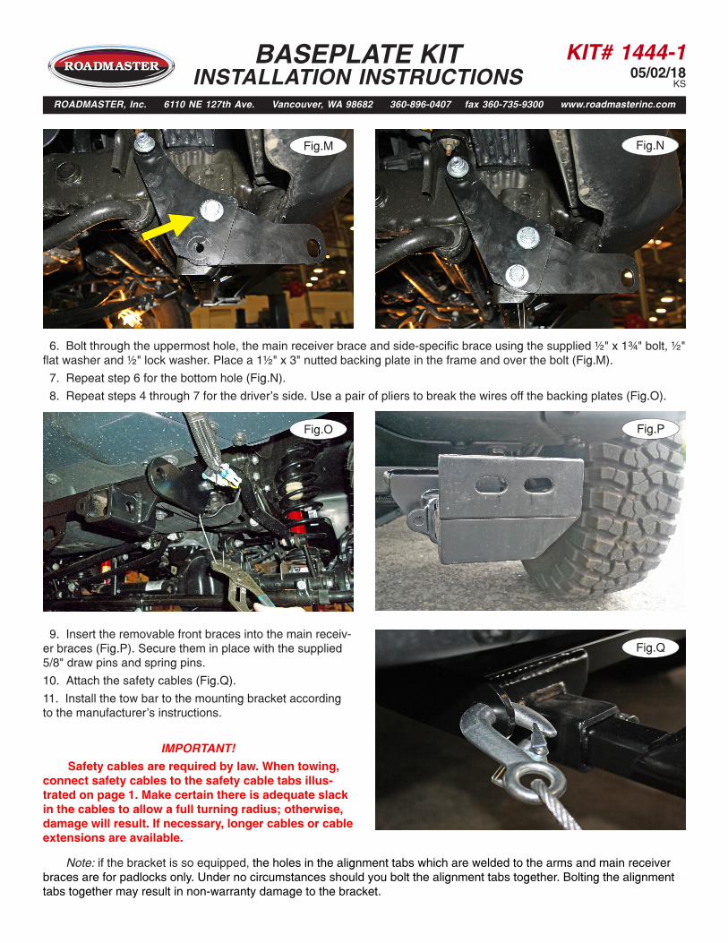
6. Bolt through the uppermost hole, the main receiver brace and side-specific brace using the supplied ½" x 1¾" bolt, ½" flat washer and ½" lock washer. Place a 1½" x 3" nutted backing plate in the frame and over the bolt (Fig.M).
7. Repeat step 6 for the bottom hole (Fig.N).
8. Repeat steps 4 through 7 for the driver's side. Use a pair of pliers to break the wires off the backing plates (Fig.O).
Fig.PFig.O
Fig.RFig.N
9. Insert the removable front braces into the main receiv-er braces (Fig.P). Secure them in place with the supplied 5/8" draw pins and spring pins.
10. Attach the safety cables (Fig.Q).
11. Install the tow bar to the mounting bracket according to the manufacturer's instructions.
IMPORTANT!
Safety cables are required by law. When towing, connect safety cables to the safety cable tabs illus-trated on page 1. Make certain there is adequate slack in the cables to allow a full turning radius; otherwise, damage will result. If necessary, longer cables or cable extensions are available.
Fig.Q
Note: if the bracket is so equipped, the holes in the alignment tabs which are welded to the arms and main receiver braces are for padlocks only. Under no circumstances should you bolt the alignment tabs together. Bolting the alignment tabs together may result in non-warranty damage to the bracket.

KIT# 1444-105/02/18
KS
BOLT TORQUE REQUIREMENTS
METRIC BOLTSThread Size Grade Torque12mm-1.25 ...........8.8 ............. 64 ft./lb. 12mm-1.5 .............8.8 ............. 60 ft./lb.12mm-1.75 ...........8.8 ............. 55 ft./lb.14mm-2.0 .............8.8 ............. 88 ft./lb.
METRIC BOLTSThread Size Grade Torque6mm-1.0 ............8.8 .............6 ft./lb. 8mm-1.0 ............8.8 ...........18 ft./lb. 8mm-1.25 ..........8.8 ...........16 ft./lb.10mm-1.25 ........8.8 .......... 36 ft./lb.10mm-1.5 ..........8.8 .......... 31 ft./lb.
STANDARD BOLTSThread Size Grade Torque5/16-18 ............5 ................ 13 ft./lb. 3/8-16 ..............5 ................ 23 ft./lb.7/16-14 ............5 ................37 ft./lb.1/2-13 ..............5 ................57 ft./lb.5/8-11 ...............5 .............. 112 ft./lb.
Note: The torque values represented below are intended as general guidelines. Torque requirements for specific applications may vary. Roadmaster does not warrant this information to be accurate for all applications and disclaims all liability for any claims or damages which may result from its use.
All illustrations and specifications contained herein are based on the latest information available at the time of publication approval. ROADMASTER, INC. reserves the right to make changes at any time without notice in material, specification and models or to discontinue models.
BASEPLATE KIT INSTALLATION INSTRUCTIONS
ROADMASTER, Inc. 6110 NE 127th Ave. Vancouver, WA 98682 360-896-0407 fax 360-735-9300 www.roadmasterinc.com
Three options for attaching the wiring plug to the main receiver brace
For six-wire plugs: use the two supplied ¾” self-tapping screws to attach the electrical plug directly to the rods on the front of the main receiver brace. For four-wire round plugs: attach to the plug mounting plate and then use the two supplied ¾” self-tapping screws to attach the mounting plate to the rods on the front of the main receiver brace. For four-wire flat plugs: place the plug through the mounting plug plate, and then secure it using the supplied zip tie on the front of the plug (Fig.R). Use the two supplied ¾” self-tapping screws to attach the mounting plate to the rods on the front of the main receiver brace.
Fig.R


