Ballistic Impact Response of Laminated Composite Panels
9
International Journal of Impact Engineering 35 (2008) 1000–1008 Ballistic impact response of laminated composite panels H.L. Gower 1 , D.S. Cronin , A. Plumtree Department of Mechanical Engineering, University of Waterloo, 200 University Ave., W, Waterloo, ON, Canada N2L 3G1 Received 16 October 2006; received in revised form 3 April 2007; accepted 23 July 2007 Available online 8 August 2007 Abstract Laminated ballistic composite panels are an important part of hard-plate protective body armour and may be subjected to a wide variety of impact conditions depending on the projectile, impact velocity and armour construction, to name a few. The ballistic response of laminated composite panels has been investigated through direct impacts of two non-deforming projectiles (7.5 mm diameter hardened steel 1201 cylindrical–conical, and 9 mm hemispherical nosed) selected to enhance different failure mechanisms including penetration and delamination. Experimental and numerical studies were carried out to determine the ballistic response of laminated Kevlar s 29 and 129 composite panels, commonly used in protective body armour. These panels were impacted at velocities between 130 and 250 m/s, which were below the penetration limit of the panels. A numerical parametric study was initially undertaken to determine those material properties which reduce back face signature (BFS; maximum dynamic displacement), one of the important performance indicators for assessing personal protection. Experimental material characterization then allowed mechanical property data to be determined for numerical simulations, which showed good agreement with the experimental data, particularly for the conical projectile impacts on both types of Kevlar s panels. Numerical simulations of the impact tests accurately predicted the BFS and dynamic response for the conical projectile impacts, while the BFS for the hemispherical projectiles was slightly low. This can be attributed to the dominant delamination failure mechanisms, which may not be completely captured by the numerical model. Importantly, the numerical analysis accurately predicted the initial velocity of the panel back face for the hemispherical projectiles and the time to reach maximum BFS for the conical projectiles. r 2007 Elsevier Ltd. All rights reserved. Keywords: Back face signature; Ballistic impact; Explicit numerical modelling; Fabric material properties woven; Laminated composites 1. Introduction Laminated ballistic composite materials may be used in protective helmets, or with ceramics and other materials for protective body armour. Standard hard plate protective body armour is made up of multiple layers, commonly including a ceramic plate to blunt and fracture projectiles and a laminated composite panel to stop the projectile while containing the ceramic particles. Armour may include an anti-trauma layer to reduce potential injury caused by dynamic deformation of the armour into the wearer. The maximum displacement of the armour during impact is described as the back face signature (BFS) [1] and is a key measure of ballistic performance. Two dominant types of composite fabric may be used in protective body armour, including aramid, specifically Kevlar s , and polyethylene-based materials such as Spec- tra s or Dyneema s . Layers of woven or unidirectional fibres are bonded using a thermoplastic or thermosetting polymer matrix. The present study has focused on the ballistic response of K29 and K129 woven Kevlar s (DuPont, USA) fabric (2 2 basket weave, 1500 denier) laminated using a polyvinyl butyral (PVB)-phenolic matrix (18% volume fraction). The design, performance and evaluation of composite panels undergoing ballistic impact require an understand- ing of material properties under high impact conditions. There are several models that describe the impact on woven composites. However, many deal with low-velocity impacts ARTICLE IN PRESS www.elsevier.com/locate/ijimpeng 0734-743X/$ - see front matter r 2007 Elsevier Ltd. All rights reserved. doi:10.1016/j.ijimpeng.2007.07.007 Corresponding author. E-mail address: [email protected] (D.S. Cronin). 1 Now at: Netherlands Institute for Metals Research, Mekelweg 2, P.O. Box 5008, Delft, The Netherlands.
-
Upload
angela-vargas -
Category
Documents
-
view
88 -
download
7
Transcript of Ballistic Impact Response of Laminated Composite Panels

ARTICLE IN PRESS
0734-743X/$ - s
doi:10.1016/j.iji
�CorrespondE-mail addr
1Now at: Ne
Box 5008, Delf
International Journal of Impact Engineering 35 (2008) 1000–1008
www.elsevier.com/locate/ijimpeng
Ballistic impact response of laminated composite panels
H.L. Gower1, D.S. Cronin�, A. Plumtree
Department of Mechanical Engineering, University of Waterloo, 200 University Ave., W, Waterloo, ON, Canada N2L 3G1
Received 16 October 2006; received in revised form 3 April 2007; accepted 23 July 2007
Available online 8 August 2007
Abstract
Laminated ballistic composite panels are an important part of hard-plate protective body armour and may be subjected to a wide
variety of impact conditions depending on the projectile, impact velocity and armour construction, to name a few.
The ballistic response of laminated composite panels has been investigated through direct impacts of two non-deforming projectiles
(7.5mm diameter hardened steel 1201 cylindrical–conical, and 9mm hemispherical nosed) selected to enhance different failure
mechanisms including penetration and delamination.
Experimental and numerical studies were carried out to determine the ballistic response of laminated Kevlars 29 and 129 composite
panels, commonly used in protective body armour. These panels were impacted at velocities between 130 and 250m/s, which were below
the penetration limit of the panels.
A numerical parametric study was initially undertaken to determine those material properties which reduce back face signature (BFS;
maximum dynamic displacement), one of the important performance indicators for assessing personal protection. Experimental material
characterization then allowed mechanical property data to be determined for numerical simulations, which showed good agreement with
the experimental data, particularly for the conical projectile impacts on both types of Kevlars panels.
Numerical simulations of the impact tests accurately predicted the BFS and dynamic response for the conical projectile impacts, while
the BFS for the hemispherical projectiles was slightly low. This can be attributed to the dominant delamination failure mechanisms,
which may not be completely captured by the numerical model. Importantly, the numerical analysis accurately predicted the initial
velocity of the panel back face for the hemispherical projectiles and the time to reach maximum BFS for the conical projectiles.
r 2007 Elsevier Ltd. All rights reserved.
Keywords: Back face signature; Ballistic impact; Explicit numerical modelling; Fabric material properties woven; Laminated composites
1. Introduction
Laminated ballistic composite materials may be used inprotective helmets, or with ceramics and other materials forprotective body armour. Standard hard plate protectivebody armour is made up of multiple layers, commonlyincluding a ceramic plate to blunt and fracture projectilesand a laminated composite panel to stop the projectilewhile containing the ceramic particles. Armour mayinclude an anti-trauma layer to reduce potential injurycaused by dynamic deformation of the armour into thewearer. The maximum displacement of the armour during
ee front matter r 2007 Elsevier Ltd. All rights reserved.
mpeng.2007.07.007
ing author.
ess: [email protected] (D.S. Cronin).
therlands Institute for Metals Research, Mekelweg 2, P.O.
t, The Netherlands.
impact is described as the back face signature (BFS) [1] andis a key measure of ballistic performance.Two dominant types of composite fabric may be used in
protective body armour, including aramid, specificallyKevlars, and polyethylene-based materials such as Spec-tras or Dyneemas. Layers of woven or unidirectionalfibres are bonded using a thermoplastic or thermosettingpolymer matrix. The present study has focused on theballistic response of K29 and K129 woven Kevlars
(DuPont, USA) fabric (2� 2 basket weave, 1500 denier)laminated using a polyvinyl butyral (PVB)-phenolic matrix(18% volume fraction).The design, performance and evaluation of composite
panels undergoing ballistic impact require an understand-ing of material properties under high impact conditions.There are several models that describe the impact on wovencomposites. However, many deal with low-velocity impacts
ARTICLE IN PRESS
Nomenclature
CS through-thickness compression strengthE1 elastic modulus in the warp directionE2 elastic modulus in the weft directionE3 through-thickness compressive modulusG12 in-plane shear modulusG23, G13through-thickness shear moduliISS interlaminar shear strengthS1 tensile strength in the warp direction
S2 tensile strength in the weft directionS12 in-plane shear strengthS23, S13 through-thickness shear strengthSN interlaminar normal strengthSTF1 strain to failure in the warp directionSTF2 strain to failure in the weft directionu12 in-plane Poisson’s ratiou23, u13 through-thickness Poisson’s ratior density
H.L. Gower et al. / International Journal of Impact Engineering 35 (2008) 1000–1008 1001
such as drop weight tests to simulate tool drop [2], wherethe failure mechanisms differ significantly from those underballistic impacts. Among the current high-speed impactmodels, many are analytical and have difficulty accountingfor deformable projectiles, or the coupled response of theprojectile and composite [3,4]. Very few numerical modelssimulating high-speed impact of projectiles involve detailedcomposite models as well as the associated response andfailure mechanisms [3]. A recent model was developed tosimulate the impact of a rigid cylinder on woven Kevlars
fabric [5]. The fabric tows were modelled independentlyand the properties used were those for Kevlars yarn. Thefailure mode of a woven fabric cannot be directly appliedto a composite panel, unfortunately, since the presence ofthe resin and multiple layers was not considered [5]. Silvaet al. [6] developed a model for predicting the perforationlimit velocity (V50) of an fragment simulating projectile(FSP) on woven Kevlars 29/Vinylester panels. Accuratepredictions of the failure modes and stress waves weremade, despite the extent of penetration being determinedby visual examination. Although this study provides someimportant information regarding modelling of ballisticimpacts, the analysis focused on projectile penetrationand not on the transient response of the panel duringthe impact.
The current study considers high-speed impact tests andapplies an existing numerical model for laminated ballisticcomposites [7] to evaluate the dominant material propertiesaffecting ballistic performance. This model provides someguidance to improve the design and enhance the develop-ment of new composite panels. In addition, the study hasbeen undertaken to evaluate the effect of the compositepanel properties on such factors as the number of pliespenetrated and the extent of BFS. This information leadsto an increased understanding of the composite panelbehaviour under ballistic conditions, while improving thepredictive capabilities of the numerical model. A smallchange in one particular material property can result in alarge change in BFS as well as the number of plies sheared,whereas another property may have more limited effects, asshown by Van Hoof [7]. Knowledge of the significantproperties that contribute to reducing BFS would enhancethe selection of new and appropriate materials, leading to
improved protection from blunt trauma and possibleweight reduction.
2. Initial ballistic composite numerical model
The ballistic numerical model initially developed by vanHoof [7] to simulate the impact and post-failure responseof a FSP on a laminated woven Kevlars 29 compositeformed the basis for this parametric study. The model wasdeveloped from that proposed by Matzenmiller, Lublinerand Taylor (MLT) [8], which assumed that each laminawas represented as a homogenized continuum. Thisapproach has been widely used to simulate impact andfailure of composite materials [7,9,10].To verify the numerical model, van Hoof conducted a
series of experimental tests with a variety of projectilesusing a range of velocities. Four different types ofprojectiles were used: 1.1 g FSP; 2.8 g FSP; 40mm long1201 conical hardened AISI 4340 steel and 40mm long 371hardened AISI 4340 steel. The conical projectiles had adiameter of 7.56mm. All the experiments used the sametargets, 10.16� 15.24 cm Kevlars 29 plates. Each plate was19 plies or 9.5mm thick. The Kevlars 29 (Mil-C-44050Type II, Class I) used was 1500 denier in a 2� 2 basketweave. The resin used contained 50% phenol formaldehydeand 50% PVB, with the low resin volume fraction of 18%being typical for armour grade composites [12].Three types of measurement systems were used to obtain
velocity–time data for the projectile. These included a high-speed X-ray IMAcon (I MAX), a Velocity InterferometerSystem for Any Reflector (VISAR) and Enhanced LaserVelocity Sensor (ELVS)[11]. BFS was determined fromprojectile displacement using the ELVS and VISAR data.The IMAX was capable of measuring the BFS in additionto the projectile displacement.As expected, BFS increased with impact velocity. For the
initial parametric study by Van Hoof [7], an FSP impact ata velocity of 461m/s was considered. This was representa-tive of previous ballistic tests from which the model wasdeveloped. Hence, since the impact and failure modecharacteristics were known for the FSP, the results couldbe validated. The model used was implemented in LS-Dyna[13], a commercial explicit finite element code. Van Hoof
ARTICLE IN PRESSH.L. Gower et al. / International Journal of Impact Engineering 35 (2008) 1000–10081002
[7] showed that those variables having the most effect onBFS were through-thickness elastic modulus, in-planeelastic modulus, through-thickness compressive strengthand in-plane strain to failure. Of these, a low through-thickness elastic modulus and a high value for each of theother parameters gave a low BFS. To reduce the number ofplies penetrated, however, a low through-thickness mod-ulus, low in-plane moduli, high compressive strength, lowthrough-thickness shear strength and high in-planestrength would be beneficial. It is worthwhile noting thatno ranking was provided for these properties in terms ofthe effect on BFS.
3. Ballistic composite numerical model development
Previously [7], small 10.16� 15.24 cm panels were usedfor impact testing and simulation, which was somewhatunrealistic since delaminations were seen to extend to theedge of the panels in some cases, resulting in reducedimpact resistance. To address this limitation, typicalarmour-sized panels, 25.4 cm� 30.48 cm (1000 � 1200), wereused for the current study. Consequently, any edge effectsin these panels would be present in actual body armour.These larger panels were made with Kevlars 129. Six ofthese panels were 19 plies thick and three were 37 pliesthick. In addition, eight 19-ply Kevlars 29 compositepanels were included in the test program to allowcomparison with the earlier work of van Hoof [7].
Two different types of projectiles were used. To ensurecontinuity and comparison with earlier work [7], a 1201conical 7.5mm diameter projectile was chosen. In addition,a 9mm diameter hemispherical nosed projectile wasincluded since it was considered to more accuratelysimulate the geometry of a projectile after passing througha ceramic facing. Both projectiles were made of heat-treated AISI 4340 steel and were 40mm in length.
The current version of the numerical model and materialconstitutive model was implemented into a recent versionof LS-DYNA (LS-DYNA 960) from VEC-DYNA [13].
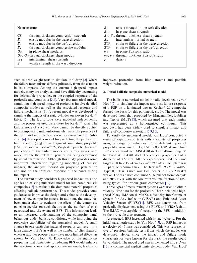
Fig. 1. Finite element mes
This included improving the finite element meshes andcontact definitions. The finite element mesh is shown inFig. 1, where each ply in the laminated panel was modelledas a separate entity with a tie–break interface used tomodel inter-ply delamination and contact. This model hasseveral advantages over that developed earlier [7]. Theelements have minimal distortion and the increase is moregradual from the small element size in the impact zone tothe large size at the edge of the panel. A similar mesh forthe smaller 10.16 cm� 15.24 cm panel was shown toaccurately reproduce the results obtained by van Hoof[7]. The new meshes were developed using the MSC/Patranpre-processor (MSC/Patran, MSC Software Corporation,Sanat Ana, CA), which defined the element sizes accordingto their location on the panel. The fewest number ofelements were distorted by using the same element sizebeside the impact zone, as that defined inside the impactzone (0.26mm), and by using an element size of 8mm atthe outer edges. This technique maintained a reasonabletransition in element size and an acceptable processor time,approximately 14–20 h for a single simulation.Quarter models were developed for the three configura-
tions tested experimentally, including a 19-ply compositeimpacted by a the 1201 conical projectile, as well as a 19-plycomposite impacted by the 9mm hemispherical projectileand a 37-ply panel impacted by the 9mm hemisphericalprojectile. Since a quarter model was used, appropriateboundary conditions were applied along the planes ofsymmetry. The nodes along the exterior edge of the shortersides of the panel were fixed in the z direction, as movementwas also restricted along these edges during the experi-ments. No restriction was placed along the longer sides.
4. Experimental panel impact testing
Experimental testing was carried out to validate theimproved numerical model. Seventeen experimental testswere conducted, including three types of composite panelsand two types of projectiles. The panels were
h of composite panel.
ARTICLE IN PRESSH.L. Gower et al. / International Journal of Impact Engineering 35 (2008) 1000–1008 1003
30.48 cm� 30.48 cm, 19-ply (9.5mm) Kevlars 29,25.4 cm� 30.48 cm, 19-ply (9.5mm) Kevlars 129 and25.4 cm� 30.48 cm, 37-ply (18.5mm) Kevlars 129. Allwere similar in size to those used in personal body armour.The projectiles used were the 1201 conical projectile used inprevious research [7] and a 9mm diameter hemisphericalended cylinder. Both were made of heat-treated AISI 4340steel, 40mm long. The impact velocities ranged from 100 to250m/s, selected to provide a range of impact energy whilenot penetrating the panels.
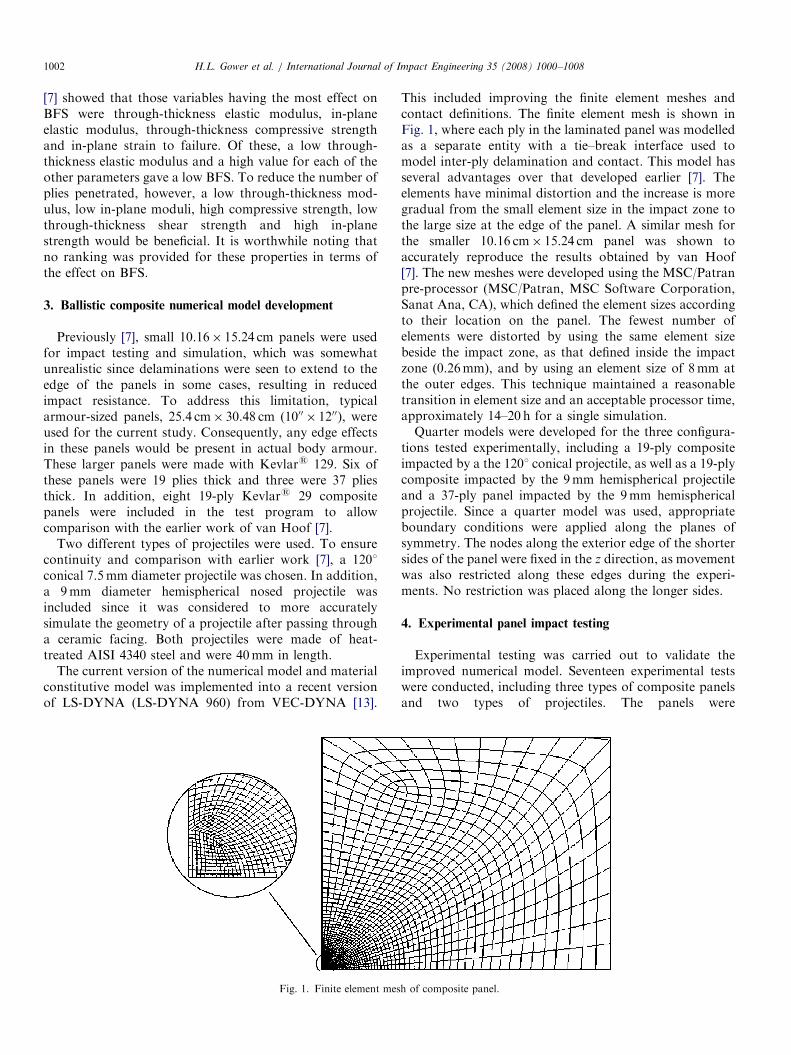
A gas gun actuated with a high-speed valve was used forthe ballistic tests. A vacuum chamber was incorporatedinto the gas gun to achieve higher projectile velocities andmore consistent impact velocities, while absorbing thepressure wave and reducing noise during firing. A lasermeasurement system was used to detect the speed of theprojectile at the barrel exit. Two ELVS systems werelocated on the vacuum chamber. The first tracked thedisplacement of the composite backplane, from which theBFS was determined, and the second that of the projectile.Fig. 2 shows both progressive displacements for the 9mmdiameter hemispherical-ended projectile impacting a 19-plyKevlars 29 composite panel at 146m/s. This figure isrepresentative of all the ballistic tests.
On impact, some backplane oscillation was apparent, asseen in Fig. 2. The projectile trace shows the displacementof its tail starting at 42mm from the composite panel(Point A0), which was the maximum width of the ELVSbeam. The projectile continued to impact the panel toPoint A corresponding to a total displacement of 65mm(25mm from A-A0, plus the projectile length of 40mm).
Fig. 2. A hemispherical-ended projectile, 9mm diameter, imp
The projectile then rebounded or fell away at Point B. Thesmall oscillations in the curve were due to debris from theprojectile sabot crossing the ELVS beam, and have noinfluence on the panel’s displacement. Since no increase inamplitude of oscillation for the projectile took place, asseen for the backplane of the composite panel, it can beassumed that the backplane oscillation was the result of thedelaminated plies vibrating, not the entire panel. This wassubsequently verified after viewing high-speed videos ofthese ballistic impacts [14].Fig. 3a is a summary plot of the BFS and corresponding
projectile velocity for all the tests. In general, the thickerpanels displayed a greater ballistic resistance evidenced bya lower BFS for all projectile velocities. It is interesting tonote that Kevlars 29 composite panels deformed lessunder impact from conical projectiles than the Kevlars 129composite panels at low-velocity impacts. However, theydeformed in a similar manner for higher-velocity impacts.It is important to note that, for the velocities considered inthis study, all of the projectiles were stopped by the panelsbefore complete penetration occurred.From Fig. 3a it can be seen that the 9mm hemispherical
projectile produced a higher BFS than the conical projectilefor the same velocity. This is to be expected since the 9mmprojectile is heavier and has higher kinetic energy for thesame velocity. However, when comparing the results basedon kinetic energy before impact, as shown in Fig. 3b, it canbe seen that the shape of the projectile was not significantfor the Kevlars 129 panels. For the Kevlars 29 panels,however, the hemispherical-nosed projectile produced ahigher BFS than the conical projectile for the same energy.
acting a 19-ply Kevlars 29 composite panel at 146m/s.

ARTICLE IN PRESS
Fig. 3. (a) BFS versus impact velocity, (b) BFS versus projectile energy.
Table 1
Comparison of numerical with experimental values for Kevlars 29
composite properties
Property Values reported
in literature [7]
Initial numerical
model values [7]
Experimental
value (static
testing)
E1 (GPa) 18.5 18.5 17.86
E2 (GPa) 18.5 18.5 8.3
E3 (GPa) 6.0 6.0
u12 0.25 0.25
u31,32 0.33 0.33
G12 (GPa) 0.77 0.77 0.85
G13,23 (GPa) 5.43 2.71
r (g/cm3) 1.23 1.23
S1 (MPa) 1850.0 555.0 444.9
S2 (MPa) 1850.0 555.0 225.5
CS (MPa) 1200.0 1200.0 �900
S12 (MPa) 77.0 77.0 56.7
S13,23 (MPa) 543.0 898.0
Sn (MPa) 34.5 34.5
ISS (MPa) 9.0 9.0
STF1 0.1 0.03 0.045
STF2 0.1 0.03 0.050
H.L. Gower et al. / International Journal of Impact Engineering 35 (2008) 1000–10081004
Although the Kevlars 29 panels deformed less thanKevlars 129 panels under impact from the conicalprojectile, the backplane displacement of the Kevlars 129panels was less than that of the Kevlars 29 panels for thehemispherical-nosed projectile. In this case, the penetrationmode for the two projectiles was different. The conicalprojectile tended to cut through the plies due to its sharpedges, whereas the hemispherical projectile caused earlydelamination to occur. This study showed that, whenconsidering blunt projectiles, the Kevlars 129 panelsshowed reduced BFS compared with the Kevlars 29panels, but had less resistance to penetration from sharpprojectiles.
5. Material properties and numerical model
Experimental tensile tests were conducted to determineor verify the composite panel material properties. Originaldata used in the model were obtained from differentsources in the literature. Table 1 compares the Kevlars 29composite panel properties obtained from earlier data [7]with those properties used in the initial numerical model, aswell as those obtained from the present experimental testprogram.
The most significant differences found in the literaturewere in the values for S13 and S23, which were used to
calibrate the model previously [7]. The through-thicknessshear strength was determined for one impact conditionand then verified with the other impact tests. The highestimpact velocity was appropriately chosen so that thenumerical model would correctly predict no penetrationsince this was the case. For calibration of both compositepanel types, the higher velocity conical projectile waschosen since the computing time was 15 times shorter thanthat for the hemispherical-ended projectile. This allowedmore simulations to be carried out, thereby giving morereliable results and a better match. The data for the 1201conical projectile impacting the 30.48 cm� 30.48 cmKevlars 29 composite panel at 241m/s was used tocalibrate the current model and determine the shearstrengths (S13, S23). Considering various values for theshear strength, a value of 898MPa was found to producethe most consistent results based on BFS. These strengthvalues were used to simulate all other impact conditions.The experimental and numerical results for tensile
modulus in the warp (01) direction, E1, were very similar.Any difference could be accounted for by strain rateeffects. The difference between the experimental andnumerical values for weft (901) direction, E2, was quitesignificant, as can be seen in Fig. 4. However, thisdifference is not considered in the current model, and theexperimental results are only approximate for staticdeformation conditions. This result highlights the fact thatthe properties may vary significantly, often depending onthe processing conditions. Improved data can be obtainedby using biaxial load conditions and testing at appro-priately high strain rates. The difference in E1 and E2 foundduring the present tensile testing may be attributed in partto the type of weaving and tension control [15]. It wasobserved that the warp tows were nearly straight; hence, a

ARTICLE IN PRESS
Fig. 4. Stress–strain curves for a 4-ply Kevlars 129 composite.
Table 2
Comparison of numerical and experimental values for Kevlars 129
material properties
Property Value used in numerical model Experimental value
E1 (GPa) 22 16.67
E2 (GPa) 22 14.0
E3 (GPa) 9.0
u12 0.25
u31,32 0.33
G12 (GPa) 0.77 1.35
G23,31 (GPa) 2.715
r (g/cm3) 1.23
S1 (MPa) 800.0 470.1
S2 (MPa) 800.0 420.4
CS (MPa) 1200.0 �900
S12 (MPa) 77.0 24.9
S23,31 (MPa) 1000.0
Sn (MPa) 34.5
ISS (MPa) 9.0
STF1 0.036 0.037
STF2 0.036 0.073
H.L. Gower et al. / International Journal of Impact Engineering 35 (2008) 1000–1008 1005
tensile test in this direction measured the force required tostretch the warp tows. The weft tows, however, undulatedover and under the warp tows, resulting in a lower initialmodulus due to fibre straightening. Although the modelhas the flexibility and capacity to assign separate values tothe warp and weft directions, this was not used since thestress–strain curves become linear at high strain rates [17].The experimental and numerical data for the in-planestrengths, corresponding to the warp and weft directions,were similar. The values for S1 were about the same, anydifferences being accounted for by strain rate effects. S2
was determined to be approximately half that of S1—thesame proportion as that for the measured tensile moduli E2
and E1. The experimental shear modulus, G12, was higherthan in the numerical model, but should be regarded as anapproximation since the lateral strain required to estimateu12 was determined from measurements of the specimenafter failure, not from strain gauges.
The material properties for the woven Kevlars 129composite panel are given in Table 2. Since little data forthe material properties of these composite panels areavailable in the literature, they were based on extendingvalues for the fibre to the composite panel. In this case, thefailure strains STF1,2 were based on the fibre failure strainof 0.03 [16]. The static elastic modulus of Kevlars 129fibres is 43% higher than that for Kevlars 29, and,allowing for the fibre volume fraction, the modulus of thecomposite was increased by 20%, giving a value of 22GPa.The quasi-static experimental value for the composite panelwas 17GPa. The higher value of 22GPa is supported byTodo et al., who reported that the tensile strength of awoven aramid/carbon fibre composite was 28% higherunder high strain rates [18]. In the model, the in-planefailure stress was based on the product of the failure strainand the elastic modulus; hence, the strengths S1, S2 wererecalculated applying the new values for modulus andfailure strain [7]. The values of S13 and S23 were unchangedfrom those used for Kevlars 29 owing to lack ofexperimental data. Since the experimental data supporteda change in elastic modulus, strength and thus failure strainwere used to calibrate the model for Kevlars 129. In thiscase, the impact on the 25.3 cm� 30.48 cm panel with theconical projectile at a velocity of 244m/s was used. Sixteencombinations of in-plane elastic modulus, compressionstrength and through-thickness shear strength were con-sidered. From this parametric study, the optimum valueswere found using the in-plane modulus of 22GPa, an in-plane strength of 800MPa and a through-thickness shearstrength of 1000MPa. These values resulted in a BFS thatwas slightly high, but the BFS occurred at the correct timeof 0.0003 s. It is recognized that other combinations ofmaterial properties may also produce satisfactory results,and this will be investigated in future studies.
6. Comparison of experimental and numerical analysis
The experimental and numerical results were comparedusing BFS, time to reach BFS and displacement–timeresponse of the composite panel. In all cases, the first0.0003 s of the impacts was simulated since this was themost significant period during which maximum backplanedeflection (and BFS) occurred.The experimental and numerical BFS–time relationships
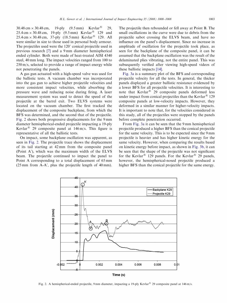
were compared for 1201 conical projectiles impactingKevlars 129 and Kevlars 29 composite panels, and9mm hemispherical projectiles impacting the Kevlars 29composite panels. Fig. 5a shows the displacement–timeplot for the 1201 conical projectile impacting Kevlars 129at 244m/s. This figure represents typical behaviour andpresents the data used to calibrate the through-thicknessshear strength for Kevlars 129. The maximum dynamicbackplane displacement obtained from the numericalmodel was within 5% of the experimental value. Fig. 5bpresents similar data for the 9mm hemispherical pro-jectile impacting a Kevlars 29 composite panel at 146m/s.
ARTICLE IN PRESS
Fig. 5. (a) A 1201 conical projectile impacting 19-ply Kevlars 129 at
244m/s. (b) A 9mm hemispherical projectile impacting Kevlars 29 at
146m/s.
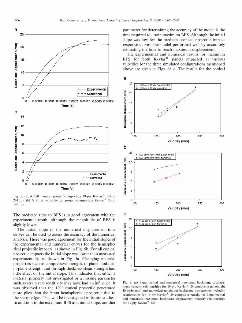
Fig. 6. (a) Experimental and numerical maximum backplane displace-
ment–velocity relationships for 19-ply Kevlars 29 composite panels. (b)
Experimental and numerical maximum backplane displacement–velocity
relationships for 19-ply Kevlars 29 composite panels. (c) Experimental
and numerical maximum backplane displacement–velocity relationships
for 19-ply Kevlars 129.
H.L. Gower et al. / International Journal of Impact Engineering 35 (2008) 1000–10081006
The predicted time to BFS is in good agreement with theexperimental result, although the magnitude of BFS isslightly lower.
The initial slope of the numerical displacement–timecurves can be used to assess the accuracy of the numericalanalysis. There was good agreement for the initial slopes ofthe experimental and numerical curves for the hemisphe-rical projectile impacts, as shown in Fig. 5b. For all conicalprojectile impacts the initial slope was lower than measuredexperimentally, as shown in Fig. 5a. Changing materialproperties such as compressive strength, in-plane modulus,in-plane strength and through-thickness shear strength hadlittle effect on the initial slope. This indicates that either amaterial property not investigated or a missing parametersuch as strain rate sensitivity may have had an influence. Itwas observed that the 1201 conical projectile penetratedmore plies than the 9mm hemispherical projectile due tothe sharp edges. This will be investigated in future studies.In addition to the maximum BFS and initial slope, another
parameter for determining the accuracy of the model is thetime required to attain maximum BFS. Although the initialslope was low for the predicted conical projectile impactresponse curves, the model performed well by accuratelyestimating the time to reach maximum displacement.The experimental and numerical results for maximum
BFS for both Kevlars panels impacted at variousvelocities for the three simulated configurations mentionedabove are given in Figs. 6a–c. The results for the conical
ARTICLE IN PRESSH.L. Gower et al. / International Journal of Impact Engineering 35 (2008) 1000–1008 1007
projectile impacting 19-ply Kevlars 29 and Kevlars 129composite panels (Figs. 6a and c) illustrate the predictivecapability of the numerical model. This compares well withprevious work [7], indicating that the model was accuratefor a 1201 conical projectile impacting a smaller 10.16 cm�15.24 cm 19-ply Kevlars 29 panel. Simulations using thehemispherical projectile (Fig. 6b) consistently gave lowerBFS values. This is attributed to the dominant delamina-tion and in-plane tension failure modes, which may not beadequately captured by the model.
Although the material properties were calibrated for aparticular set of test conditions, these figures indicated thatthe properties used had the capacity of being applied toother configurations for the same material. This would beacceptable if all other factors were correct. The materialproperties were determined for a particular Kevlars
composite panel using values from the literature andexperiments, then calibrating the through-thickness shearstrength using the highest impact velocity of the conicalprojectile. This procedure proved to be very satisfactory forimpacts on Kevlars 29 composite panels. The selection ofmaterial properties was well balanced. The numericalresults for the hemispherical projectile impacting Kevlars
129 composite panels resulted in a BFS that was slightlylower than that observed experimentally. This was also the
Fig. 7. Quarter model of 9mm hemispherical p
Fig. 8. (a, b) Cross-section comparing numerical [right] with
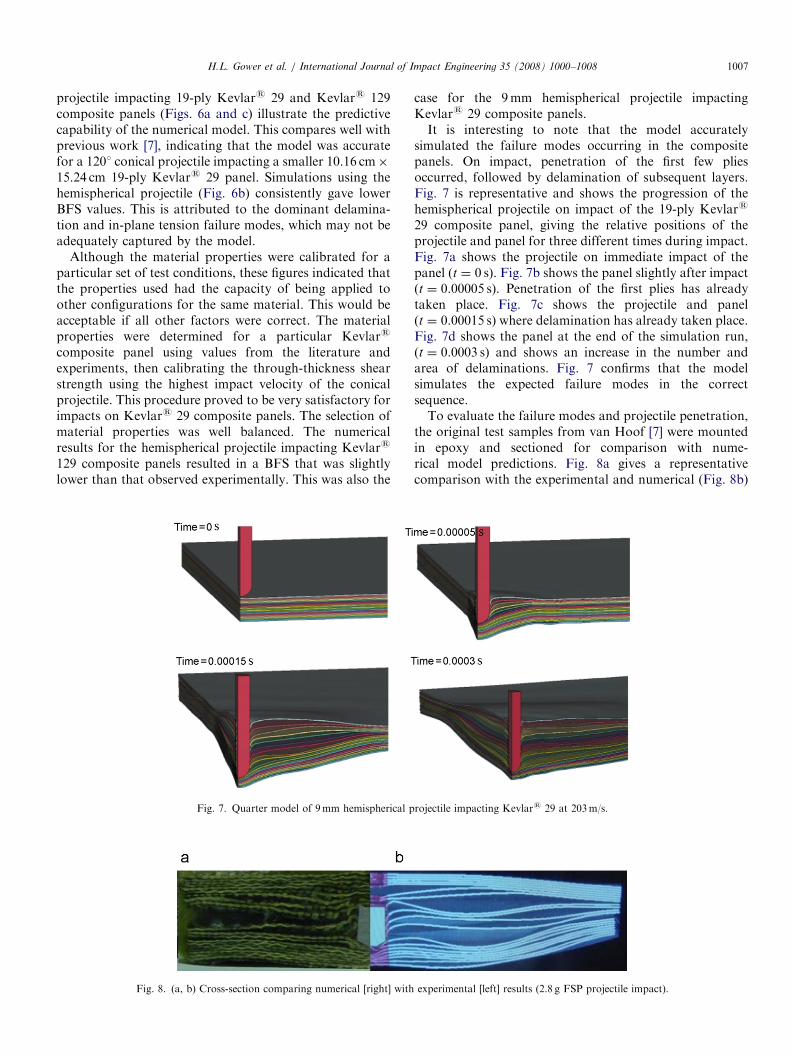
case for the 9mm hemispherical projectile impactingKevlars 29 composite panels.It is interesting to note that the model accurately
simulated the failure modes occurring in the compositepanels. On impact, penetration of the first few pliesoccurred, followed by delamination of subsequent layers.Fig. 7 is representative and shows the progression of thehemispherical projectile on impact of the 19-ply Kevlars
29 composite panel, giving the relative positions of theprojectile and panel for three different times during impact.Fig. 7a shows the projectile on immediate impact of thepanel (t ¼ 0 s). Fig. 7b shows the panel slightly after impact(t ¼ 0.00005 s). Penetration of the first plies has alreadytaken place. Fig. 7c shows the projectile and panel(t ¼ 0.00015 s) where delamination has already taken place.Fig. 7d shows the panel at the end of the simulation run,(t ¼ 0.0003 s) and shows an increase in the number andarea of delaminations. Fig. 7 confirms that the modelsimulates the expected failure modes in the correctsequence.To evaluate the failure modes and projectile penetration,
the original test samples from van Hoof [7] were mountedin epoxy and sectioned for comparison with nume-rical model predictions. Fig. 8a gives a representativecomparison with the experimental and numerical (Fig. 8b)
rojectile impacting Kevlars 29 at 203m/s.
experimental [left] results (2.8 g FSP projectile impact).

ARTICLE IN PRESSH.L. Gower et al. / International Journal of Impact Engineering 35 (2008) 1000–10081008
cross-sections for a 2.8 g FSP impacting a 10.16 cm�15.24 cm panel at 490m/s. This figure illustrates theanticipated penetration and delamination failure modesat the corresponding levels within the panel. It is importantto note that the predicted penetration into the panel is inexcellent agreement with that observed experimentally.
7. Conclusions
An experimental and numerical ballistic study has beenundertaken to investigate the dynamic response of Kevlars
composite panels to impacts from non-deforming conicaland hemispherical projectiles. Importantly, the sizes of thepanels used in this study were chosen to be representativeof those used in personal body armour.
An initial numerical study of ballistic impacts onKevlars composite panels indicated that an increased in-plane modulus, in-plane strain to failure and through-thickness compression strength would reduce the BFS ofwoven Kevlars composites. In addition, reducing thethrough-thickness elastic modulus was predicted to bebeneficial in reducing backplane displacement.
Experimental characterization of the stress–strain beha-viour of the warp and weft exhibited two distinct slopes.The first corresponded to straightening, and the second tothe stretching of the tows. Mechanical testing data gavedifferent property values than those used in the numericalmodel, especially for the in-plane strengths. The valuesused for the simulations were more than twice that foundduring experiments, attributed to strain rate effects in thematerial and consistent with data reported in the literature.
The BFS predictions for the simulations of conicalprojectile impacts on Kevlars 29 were in good agreementwith the experimental results, whereas the predicted BFSfor the hemispherical projectile impacts on Kevlars 29were consistently lower. This is attributed to increaseddelamination taking place within the panel. The experi-mental and numerical results for the conical projectileimpacts on Kevlars 129 were in close agreement. Simula-tions correctly predicted the time to BFS for the conicalprojectiles. The numerical prediction of the velocity–timehistory for the hemispherical projectile impacting theKevlars 129 panels was accurate, although the BFSprediction was low.
Experimental testing showed that Kevlars 29 exhibiteda lower BFS than the Kevlars 129 at low impact speeds;however, this changed for higher velocity impacts. In thisstudy, when considering blunt projectiles, the Kevlars 129panels showed reduced BFS compared with the Kevlars 29panels, and displayed less resistance to penetration fromsharp projectiles.
Acknowledgements
The authors gratefully acknowledge financial supportduring the course of this research from Ontario Centres ofExcellence (OCE), Defence R&D Canada - Valcartier(Valcartier, Quebec) and Barrday Inc. (Cambridge, Ontar-io). The authors also thank Professor Michael Worswick atthe University of Waterloo for his support and assistance.
References
[1] National Institute of Justice. Ballistic resistance of personal body
armor, NIJ Standard 0101.04.
[2] Roy T, Chakraborty D. Delamination in hybrid FRP laminates
under low velocity impact. J Reinf Plast Compos 2006;25(18):
1939–56.
[3] Naik NK, Shirirao P, Reddy BCK. Ballistic behaviour of woven
fabric composites: formulation. Int J Impact Eng 2006;32(9):1521–2.
[4] Naik NK, Shirirao P, Reddy BCK. Ballistic behaviour of woven
fabric composites. Mater Sci Eng A 2005;412(1–2):104–16.
[5] Duan Y, Keefe M, Bogetti TA, Powers B. Finite element modeling of
transverse impact on a ballistic fabric. Int J Mater Sci 2006;48(1):
33–43.
[6] Silva MAG, Cismas-iu C, Chiorean CG. Numerical simulation of
ballistic impact on composite laminates. Int J Impact Eng 2005;31(3):
289–306.
[7] van Hoof J. Modelling impact induced delamination in composite
materials. Ottawa: Carleton University; 1999.
[8] Matzenmiller A, Lubliner J, Taylor RL. A constitutive model for
anisotropic damage in fiber-composites. Mech Mater 1995;20(2):
125–52.
[9] Floyd A, Cronin D, Vaziri R, Poursartip A, Worswick M, Plumtree
A. Three-dimensional numerical simulation of the ballistic response
of laminated composite plates. Contract report for the Defence
Research Establishment, Valcartier, June 2001.
[10] Williams KV, Vaziri R. Application of a damage mechanics model
for predicting the impact response of composite materials. Comput
Struct 2001;79(1):997–1011.
[11] Starratt D, Sanders T, Cepus E, Poursartip A, Vaziri R. An efficient
method for continuous measurement of projectile motion in ballistic
impact experiments. Int J Impact Eng 2000;24(2):155–70.
[12] Lee B, Walsh TF, Won ST, Patts HM, Song JW, Mayer AH.
Penetration failure mechanisms of armour-grade fibre composites
under impact. J Compos Mater 2001;35(18):1605–33.
[13] Halquist JO. LS-Dyna theoretical manual LSTC. California, 1998.
[14] Gower HL. Ballistic impact response of woven Kevlar composites.
Waterloo: University of Waterloo; 2003.
[15] Ito M, Chou T. An analytical and experimental study of strength and
failure behavior of plain weave composites. J Compos Mater 1998;
32(1):2–30.
[16] Dooraki FB, Nemes JA, Bolduc M. Study of parameters affecting the
strength of yarns. J Phys IV France 2006;134:1183–8.
[17] Chocron Benloulo IS, Rodrıguez J, Martınez MA, Sanchez Galvez V.
Dynamic tensile testing of aramid and polyethylene fiber composites.
Int J Impact Eng 1997;19(2):135–46.
[18] Todo M, Takahashi K, Beguelin P, Kausch H. Strain-rate
dependence of the tensile fracture behaviour of woven-cloth
reinforced polyamide composites. Compos Sci Tech 2000;60(5):
763–71.