Ball Valves - HTChydroarabia.com/Products/Pipeline Supplies/Valves/General...Bronze Ball Valves *-20...
124
AHEAD OF THE FLOW TM Ball Valves CATALOG C-BV-1201
Transcript of Ball Valves - HTChydroarabia.com/Products/Pipeline Supplies/Valves/General...Bronze Ball Valves *-20...
A H E A D O F T H E F L O WTM
B a l l Va l v e s
CCAATTAALLOOGG CC-BBVV-11220011
NIBCO INC. WORLD HEADQUARTERS • 1516 MIDDLEBURY ST. • ELKHART, IN 46516-4740 • USA • PH: 1.800.234.0227 TECH SERVICES PH:1.888.446.4226 • FAX: 1.888.336.4226 • INTERNATIONAL OFFICE PH: +1.574.295.3221 • FAX: +1.574.295.3455
www.nibco.com
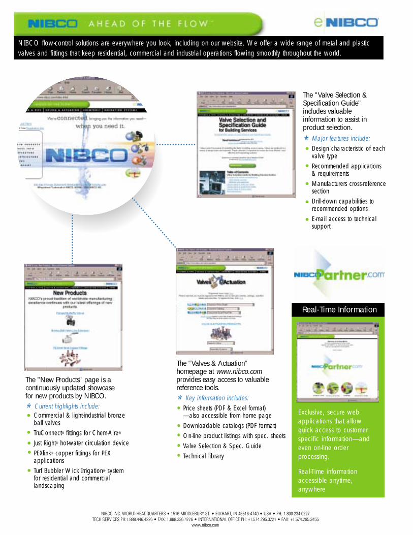
NIBCO flow-control solutions are everywhere you look, including on our website. We offer a wide range of metal and plasticvalves and fittings that keep residential, commercial and industrial operations flowing smoothly throughout the world.
Commercial & light-industrial bronzeball valvesTruConnect® fittings for Chem-Aire®
Just Right® hot-water circulation devicePEXlink® copper fittings for PEX applicationsTurf Bubbler Wick Irrigation® systemfor residential and commercial landscaping
The "New Products" page is acontinuously updated showcase for new products by NIBCO.
* Current highlights include:
Design characteristic of eachvalve typeRecommended applications & requirementsManufacturers cross-referencesectionDrill-down capabilities to recommended optionsE-mail access to technicalsupport
The "Valve Selection &Specification Guide"includes valuable information to assist inproduct selection.
* Major features include:
Real-Time Information
Exclusive, secure webapplications that allowquick access to customerspecific information—andeven on-line order processing.
Real-Time informationaccessible anytime, anywhere
Price sheets (PDF & Excel format)—also accessible from home pageDownloadable catalogs (PDF format)On-line product listings with spec. sheetsValve Selection & Spec. GuideTechnical library
The “Valves & Actuation” homepage at www.nibco.comprovides easy access to valuablereference tools.
* Key information includes:
A H E A D O F T H E F L O W ™
wwwwww..nniibbccoo..ccoomm
3NIBCO INC. WORLD HEADQUARTERS • 1516 MIDDLEBURY ST. • ELKHART, IN 46516-4740 • USA • PH: 1.800.234.0227
TECH SERVICES PH: 1.888.446.4226 • FAX: 1.888.336.4226 • INTERNATIONAL OFFICE PH: +1.574.295.3221 • FAX: +1.574.295.3455www.nibco.com
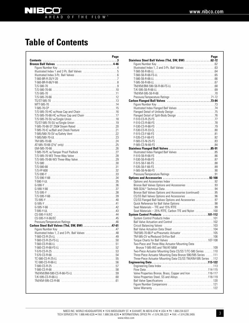
Table of Contents
A H E A D O F T H E F L O W ™
wwwwww..nniibbccoo..ccoomm
3
PageContents . . . . . . . . . . . . . . . . . . . . . . . . . . . . . . . . . . . . . . . . . . . . . . . . .3Bronze Ball Valves . . . . . . . . . . . . . . . . . . . . . . . . . . . . . . . . . . . . . 4-46
Figure Number Key . . . . . . . . . . . . . . . . . . . . . . . . . . . . . . . . . . . . . . .4Illustrated Index 1 and 2-Pc. Ball Valves . . . . . . . . . . . . . . . . . . . . . . 5Illustrated Index 3-Pc. Ball Valves . . . . . . . . . . . . . . . . . . . . . . . . . . . .6T-560-BR-R-20/Y-20 . . . . . . . . . . . . . . . . . . . . . . . . . . . . . . . . . . . . . .7T-560-BR-R-66/Y-66 . . . . . . . . . . . . . . . . . . . . . . . . . . . . . . . . . . . . . . .8T/S-580-70 . . . . . . . . . . . . . . . . . . . . . . . . . . . . . . . . . . . . . . . . . . . . .9T/S-580-70-66 . . . . . . . . . . . . . . . . . . . . . . . . . . . . . . . . . . . . . . . . . .10T/S-585-70 . . . . . . . . . . . . . . . . . . . . . . . . . . . . . . . . . . . . . . . . . . . .11T/S-585-70-66 . . . . . . . . . . . . . . . . . . . . . . . . . . . . . . . . . . . . . . . . . .12TS/ST-585-70 . . . . . . . . . . . . . . . . . . . . . . . . . . . . . . . . . . . . . . . . . .13MTT-585-70 . . . . . . . . . . . . . . . . . . . . . . . . . . . . . . . . . . . . . . . . . . . .14T-585-70-CP . . . . . . . . . . . . . . . . . . . . . . . . . . . . . . . . . . . . . . . . . . . .15T/S-585-70-HC w/Hose Cap and Chain . . . . . . . . . . . . . . . . . . . . . . .16T/S-585-70-66-HC w/Hose Cap and Chain . . . . . . . . . . . . . . . . . . . . . . . . .17T/S-585-70-SU w/Single Union . . . . . . . . . . . . . . . . . . . . . . . . . . . . .18TS/ST-585-70-SU w/Single Union . . . . . . . . . . . . . . . . . . . . . . . . . . .19T-585-70-66-ST 250# Steam Rated . . . . . . . . . . . . . . . . . . . . . . . . . .20T-585-70-IC w/Ball and Check Feature . . . . . . . . . . . . . . . . . . . . . . .21T-585/580-70-SV w/Safety Vent . . . . . . . . . . . . . . . . . . . . . . . . . . . .22T-585/580-70-UL . . . . . . . . . . . . . . . . . . . . . . . . . . . . . . . . . . . . . . . .23TM-585-70-66 . . . . . . . . . . . . . . . . . . . . . . . . . . . . . . . . . . . . . . . . . .24AT-585-70-66 (2¹⁄₂" only) . . . . . . . . . . . . . . . . . . . . . . . . . . . . . . . . . .25GM-585-70-66 . . . . . . . . . . . . . . . . . . . . . . . . . . . . . . . . . . . . . . . . . .26T-585-70-PL w/Tamper Proof Padlock . . . . . . . . . . . . . . . . . . . . . . . .27T/S-585-70-W3 Three-Way Valve . . . . . . . . . . . . . . . . . . . . . . . . . . .28T/S-585-70-66-W3 Three-Way Valve . . . . . . . . . . . . . . . . . . . . . . . . .29T/S-580 . . . . . . . . . . . . . . . . . . . . . . . . . . . . . . . . . . . . . . . . . . . . . . .30T/S-580-66 . . . . . . . . . . . . . . . . . . . . . . . . . . . . . . . . . . . . . . . . . . . .31T/S-FP-600 . . . . . . . . . . . . . . . . . . . . . . . . . . . . . . . . . . . . . . . . . . . .32T/S-590-Y . . . . . . . . . . . . . . . . . . . . . . . . . . . . . . . . . . . . . . . . . . . . .33T/S-590-Y-66 . . . . . . . . . . . . . . . . . . . . . . . . . . . . . . . . . . . . . . . . . . .34T-590-Y-UL . . . . . . . . . . . . . . . . . . . . . . . . . . . . . . . . . . . . . . . . . . . .35G-590-Y . . . . . . . . . . . . . . . . . . . . . . . . . . . . . . . . . . . . . . . . . . . . . . .36G-590-Y-66 . . . . . . . . . . . . . . . . . . . . . . . . . . . . . . . . . . . . . . . . . . . .37T/S-595-Y . . . . . . . . . . . . . . . . . . . . . . . . . . . . . . . . . . . . . . . . . . . . .38T/S-595-Y-66 . . . . . . . . . . . . . . . . . . . . . . . . . . . . . . . . . . . . . . . . . . .39TS-595-Y . . . . . . . . . . . . . . . . . . . . . . . . . . . . . . . . . . . . . . . . . . . . . .40G-595-Y . . . . . . . . . . . . . . . . . . . . . . . . . . . . . . . . . . . . . . . . . . . . . . .41G-595-Y-66 . . . . . . . . . . . . . . . . . . . . . . . . . . . . . . . . . . . . . . . . . . . .42T-595-Y-UL . . . . . . . . . . . . . . . . . . . . . . . . . . . . . . . . . . . . . . . . . . . .43CS-595-Y-X/EC . . . . . . . . . . . . . . . . . . . . . . . . . . . . . . . . . . . . . . . . .44CS-595-Y-X-66/EC . . . . . . . . . . . . . . . . . . . . . . . . . . . . . . . . . . . . . . .45Pressure/Temperature Ratings . . . . . . . . . . . . . . . . . . . . . . . . . . . . .46
Carbon Steel Ball Valves (Thd, SW, BW) . . . . . . . . . . . . . . . . . . .47-61Figure Number Key . . . . . . . . . . . . . . . . . . . . . . . . . . . . . . . . . . . . . .47Illustrated Index 1, 2 and 3-Pc. Ball Valves . . . . . . . . . . . . . . . . . . . .48T-560-CS-R-25-LL . . . . . . . . . . . . . . . . . . . . . . . . . . . . . . . . . . . . . . .49T-560-CS-R-25-FS-LL . . . . . . . . . . . . . . . . . . . . . . . . . . . . . . . . . . . . .50T-560-CS-R-66-LL . . . . . . . . . . . . . . . . . . . . . . . . . . . . . . . . . . . . . . .51T-560-CS-R-66-FS-LL . . . . . . . . . . . . . . . . . . . . . . . . . . . . . . . . . . . . .52T-570-CS-R-25 . . . . . . . . . . . . . . . . . . . . . . . . . . . . . . . . . . . . . . . . . .53T-570-CS-R-66 . . . . . . . . . . . . . . . . . . . . . . . . . . . . . . . . . . . . . . . . . .54TC-580-CS-R-25-LL . . . . . . . . . . . . . . . . . . . . . . . . . . . . . . . . . . . . . .55TC-580-CS-R-66-LL . . . . . . . . . . . . . . . . . . . . . . . . . . . . . . . . . . . . . .56T-580-CS-R-25 . . . . . . . . . . . . . . . . . . . . . . . . . . . . . . . . . . . . . . . . . .57T-580-CS-R-66 . . . . . . . . . . . . . . . . . . . . . . . . . . . . . . . . . . . . . . . . . .58TM/KM/BM-590-CS-R-66-FS-LL . . . . . . . . . . . . . . . . . . . . . . . . . . . .59T/K-595-CS-R-66-LL . . . . . . . . . . . . . . . . . . . . . . . . . . . . . . . . . . . . . .60TM/KM-595-CS-R-66 . . . . . . . . . . . . . . . . . . . . . . . . . . . . . . . . . . . .61
PageStainless Steel Ball Valves (Thd, SW, BW) . . . . . . . . . . . . . . . . .62-72
Figure Number Key . . . . . . . . . . . . . . . . . . . . . . . . . . . . . . . . . . . . . .62Illustrated Index 1, 2 and 3-Pc. Ball Valves . . . . . . . . . . . . . . . . . . . .63T-560-S6-R-66-LL . . . . . . . . . . . . . . . . . . . . . . . . . . . . . . . . . . . . . . . .64T-560-S6-R-66-FS-LL . . . . . . . . . . . . . . . . . . . . . . . . . . . . . . . . . . . . .65T-580-S6-R-66-LL . . . . . . . . . . . . . . . . . . . . . . . . . . . . . . . . . . . . . . . .66T-585-S6-R-66-LL . . . . . . . . . . . . . . . . . . . . . . . . . . . . . . . . . . . . . . . .67TM/KM/BM-590-S6-R-66-FS-LL . . . . . . . . . . . . . . . . . . . . . . . . . . . .68T/K-595-S6-R-66-LL . . . . . . . . . . . . . . . . . . . . . . . . . . . . . . . . . . . . . .69TM/KM-595-S6-R-66 . . . . . . . . . . . . . . . . . . . . . . . . . . . . . . . . . . . . .70Pressure/Temperature Ratings . . . . . . . . . . . . . . . . . . . . . . . . . . .71-72
Carbon Flanged Ball Valves . . . . . . . . . . . . . . . . . . . . . . . . . . . . .73-84Figure Number Key . . . . . . . . . . . . . . . . . . . . . . . . . . . . . . . . . . . . . .73Illustrated Index Flanged Ball Valves . . . . . . . . . . . . . . . . . . . . . . . . .74Flanged Detail of Unibody Design . . . . . . . . . . . . . . . . . . . . . . . . . . .75Flanged Detail of Split-Body Design . . . . . . . . . . . . . . . . . . . . . . . . .76F-510-CS-R-25-FS . . . . . . . . . . . . . . . . . . . . . . . . . . . . . . . . . . . . . . .77F-510-CS-R-66-FS . . . . . . . . . . . . . . . . . . . . . . . . . . . . . . . . . . . . . . .78F-530-CS-R-66-FS . . . . . . . . . . . . . . . . . . . . . . . . . . . . . . . . . . . . . . .79F-530-CS-R-33-CL . . . . . . . . . . . . . . . . . . . . . . . . . . . . . . . . . . . . . . .80F-515-CS-F-66-FS . . . . . . . . . . . . . . . . . . . . . . . . . . . . . . . . . . . . . . .81F-535-CS-F-66-FS . . . . . . . . . . . . . . . . . . . . . . . . . . . . . . . . . . . . . . .82F-565-CS-N-25-FS . . . . . . . . . . . . . . . . . . . . . . . . . . . . . . . . . . . . . . .83F-565-CS-N-66-FS . . . . . . . . . . . . . . . . . . . . . . . . . . . . . . . . . . . . . . .84
Stainless Flanged Ball Valves . . . . . . . . . . . . . . . . . . . . . . . . . . . .85-91Illustrated Index Flanged Ball Valves . . . . . . . . . . . . . . . . . . . . . . . . .85F-510-S6-R-66-FS . . . . . . . . . . . . . . . . . . . . . . . . . . . . . . . . . . . . . . .86F-530-S6-R-66-FS . . . . . . . . . . . . . . . . . . . . . . . . . . . . . . . . . . . . . . .87F-515-S6-F-66-FS . . . . . . . . . . . . . . . . . . . . . . . . . . . . . . . . . . . . . . . .88F-535-S6-F-66-FS . . . . . . . . . . . . . . . . . . . . . . . . . . . . . . . . . . . . . . . .89F-565-S6-N-66-FS . . . . . . . . . . . . . . . . . . . . . . . . . . . . . . . . . . . . . . .90Pressure/Temperature Ratings . . . . . . . . . . . . . . . . . . . . . . . . . . . . .91
Options and Accessories . . . . . . . . . . . . . . . . . . . . . . . . . . . . . . .92-100Options and Accessories Index . . . . . . . . . . . . . . . . . . . . . . . . . . . . .92Bronze Ball Valves Options and Accessories . . . . . . . . . . . . . . . . . . .93NIB-SEAL® Technical Data . . . . . . . . . . . . . . . . . . . . . . . . . . . . . . . . .94Bronze Ball Valves Options and Accessories (continued) . . . . . . . . . .95CS/SS Ball Valves Options and Accessories . . . . . . . . . . . . . . . . . . .96CS/SS Flanged Ball Valves Options and Accessories . . . . . . . . . . . . .97Quick Reference for Ball Valve Options . . . . . . . . . . . . . . . . . . . . . . .98Seat Materials – TFE and 15% RTFE . . . . . . . . . . . . . . . . . . . . . . . . .99Seat Materials – 25% RTFE, Carbon TFE and Nylon . . . . . . . . . . . .100
System Control Products . . . . . . . . . . . . . . . . . . . . . . . . . . . . . .101-112System Control Products Index . . . . . . . . . . . . . . . . . . . . . . . . . . . .101Ball Valve Actuation and Control . . . . . . . . . . . . . . . . . . . . . . . . . . .102Circuit Balancing Valves . . . . . . . . . . . . . . . . . . . . . . . . . . . . . . . . .103Ball Valve Actuation Data Sheet . . . . . . . . . . . . . . . . . . . . . . . . . . .104TM/585-70-66-P w/Pneumatic Actuator . . . . . . . . . . . . . . . . . . . . .105TM-585-CV w/Reduced Orifice Ball . . . . . . . . . . . . . . . . . . . . . . . . .106Torque Charts for Ball Valves . . . . . . . . . . . . . . . . . . . . . . . . . .107-108Two-Piece and Three-Way Actuator Mounting Data
Bronze T-585-WS and TM/AT-5858 . . . . . . . . . . . . . . . . . . . . . . .109Two-Piece Actuator Mounting Data CS/SS T/TC-580 Series . . . . . .110Three-Piece Actuator Mounting Data Bronze 590/595 Series . . . . .111Three-Piece Actuator Mounting Data CS/SS TM/KM-595 Series . .112
Engineering Data . . . . . . . . . . . . . . . . . . . . . . . . . . . . . . . . . . . . .113-122Engineering Data Index . . . . . . . . . . . . . . . . . . . . . . . . . . . . . . . . . .113Flow Data . . . . . . . . . . . . . . . . . . . . . . . . . . . . . . . . . . . . . . . . .114-115Valve Properties Bronze, Brass, Copper and Iron . . . . . . . . . . .116-117Valve Properties Steel, SS and Alloys . . . . . . . . . . . . . . . . . . . .118-119Ball Valve Specifications . . . . . . . . . . . . . . . . . . . . . . . . . . . . . . . . .120Figure Number Comparisons . . . . . . . . . . . . . . . . . . . . . . . . . . . . . .121Valve Warranty . . . . . . . . . . . . . . . . . . . . . . . . . . . . . . . . . . . . . . . .122

A H E A D O F T H E F L O W ™
wwwwww..nniibbccoo..ccoomm
4NIBCO INC. WORLD HEADQUARTERS • 1516 MIDDLEBURY ST. • ELKHART, IN 46516-4740 • USA • PH: 1.800.234.0227
TECH SERVICES PH: 1.888.446.4226 • FAX: 1.888.336.4226 • INTERNATIONAL OFFICE PH: +1.574.295.3221 • FAX: +1.574.295.3455www.nibco.com
Bronze Ball ValvesOne, Two, and Three-Piece Body Threaded, Solder and Grooved Ends
Bronze Ball Valve Figure Number Key
T-560-BR-R-20-**
BM - Butt Weld ISOMount
G - GroovedGM - Grooved ISO MountKM - Socket Weld ISO
MountMTT - Male x Female
ThreadS - Solder
ST - Solder x ThreadT - Thread
TC - Thread (investment cast carbon body)
TM - Thread ISO MountTS - Thread x Solder
560 - One-Piece Body Reduced Port 600 PSI
580 - Two-PieceConventional Port400 PSI
580-70- Two-Piece Conventional Port 600 PSI
585-70 - Two-Piece Full Port 600 PSI
585-CV - Two-Piece with aFlow Control Port
590 - Three-Piece Body Conventional Port600 PSI
595 - Three-Piece Body Full Port600 PSI
*BR - Bronze R - ReinforcedY - Virgin TFE
20 - Bronze66 - Stainless Steel
**70 - Bronze/Chrome Plated Ball
BSP - British Standard Thread(Parallel)
BST - British Thread (Taper)
CP - Chrome PlatedEL - Extended Lever
HC - Hose Cap and ChainHCL - Horizontal Chain Lever
IC - Integral CheckLL - Locking LeverM - Memory Stop
NS - NIB-SEAL® HandleOL - Oval LockingOV - Oval HandlePL - Padlock Handle
RH - Round HandleST - Steam ServiceSU - Single Union EndSV - Safety VentUL - UL Listed
VCL - Vertical Chain LeverW3 - Three-Way ValveWH - Wing Handle
X - Oxygen Cleaned* BR only applies to T-560 line.
** 70 only applies to T or S-580-70 and T or S-585-70 series valves.
This key is a guide only and is not intended to infer that every valve combination will be produced. Key for threaded, socket weld, grooved end ball valves.
De-alloying corrosion, known as ”Dezincification,“ was effectively eradicated from valve products in the 1950s.Today, however, this problem has returned with the increased use of high-zinc alloys (commonly referred to as‘Yellow Brass’) in forged and cast valves typically produced outside the United States.
Dezincification selectively removes zinc from the alloy, leaving behind a porous, copper-rich structure that has little mechanical strength. Thephysical attributes of an in-service valve with Dezincification includes a white powdery substance or mineral stains on its exterior surface.
What’s the cure? On all bronze valves the metal components in the waterway must not contain more than 15%zinc in their chemical makeup. As a standard NIBCO bronze ball valves are made to be “DezincificationResistant,” which is a seal of quality and longevity.
DezincificationResistant
End Connection
ValveStyle
BasicMaterial
SeatMaterial
TrimMaterial Options
Mahood
Highlight
Mahood
Highlight
Mahood
Highlight
Mahood
Highlight
Mahood
Highlight
A H E A D O F T H E F L O W ™
wwwwww..nniibbccoo..ccoomm
5NIBCO INC. WORLD HEADQUARTERS • 1516 MIDDLEBURY ST. • ELKHART, IN 46516-4740 • USA • PH: 1.800.234.0227
TECH SERVICES PH: 1.888.446.4226 • FAX: 1.888.336.4226 • INTERNATIONAL OFFICE PH: +1.574.295.3221 • FAX: +1.574.295.3455www.nibco.com
A H E A D O F T H E F L O W ™
wwwwww..nniibbccoo..ccoomm
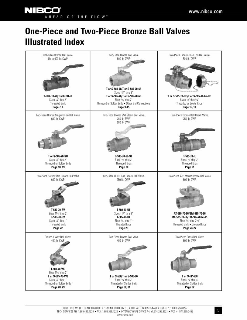
One-Piece and Two-Piece Bronze Ball ValvesIllustrated Index
One-Piece Bronze Ball ValveUp to 600 lb. CWP
Two-Piece Bronze Ball Valve600 lb. CWP
T-560-BR-20/T-560-BR-66Sizes ¹⁄₄" thru 2"Threaded Ends
Page 7, 8
Two-Piece Bronze Single Union Ball Valve600 lb. CWP
T or S-585-70-SUSizes ¹⁄₂" thru 2"
Threaded or Solder EndsPage 18, 19
Two-Piece Safety Vent Bronze Ball Valve600 lb. CWP
T-580-70-SVSizes 1¹⁄₄" thru 2"
T-585-70-SVSizes ¹⁄₄" thru 1"Threaded Ends
Page 22
Bronze 3-Way Ball Valve400 lb. CWP
T-580-70-W3Sizes 1¹⁄₄" thru 2"
T or S-585-70-W3Sizes ¹⁄₂" thru 1"
Threaded or Solder EndsPage 28, 29
Two-Piece Bronze Ball Valve400 lb. CWP
T or S-580/T or S-580-66Sizes ¹⁄₄" thru 2"
Threaded or Solder EndsPage 30, 31
Two-Piece Brass Ball Valve600 lb. CWP
T or S-FP-600Sizes ¹⁄₄" thru 4"
Threaded or Solder EndsPage 32
Two-Piece UL/LP Gas Bronze Ball Valve250 lb. CWP
T-580-70-ULSizes 1¹⁄₄" thru 3"
T-585-70-ULSizes ¹⁄₄" thru 1"Threaded Ends
Page 23
Two-Piece Act. Mount Bronze Ball Valve600 lb. CWP
AT-580-70-66/GM-585-70-66TM-585-70-66/TM-585-70-66-PL
Sizes ¹⁄₂" thru 2¹⁄₂"Threaded Ends • Grooved Ends
Page 24-27
Two-Piece Bronze 250 Steam Ball Valve250 lb. SWP600 lb. CWP
T-585-70-66-STSizes ¹⁄₂" thru 2"Threaded Ends
Page 20
Two-Piece Bronze Ball Check Valve250 lb. CWP
T-585-70-ICSizes ¹⁄₂" thru 2"Threaded Ends
Page 21
T or S-580-70/T or S-580-70-66Sizes 1¹⁄₄" thru 3"
T or S-585-70/T or S-585-70-66Sizes ¹⁄₄" thru 2"
Threaded or Solder Ends • Other End ConnectionsPage 9-15
Two-Piece Bronze Hose End Ball Valve600 lb. CWP
T or S-585-70-HC/T or S-585-70-66-HCSizes ¹⁄₂" thru ³⁄₄"
Threaded or Solder EndsPage 16, 17
NIBCO INC. WORLD HEADQUARTERS • 1516 MIDDLEBURY ST. • ELKHART, IN 46516-4740 • USA • PH: 1.800.234.0227 TECH SERVICES PH: 1.888.446.4226 • FAX: 1.888.336.4226 • INTERNATIONAL OFFICE PH: +1.574.295.3221 • FAX: +1.574.295.3455
www.nibco.com
A H E A D O F T H E F L O W ™
wwwwww..nniibbccoo..ccoomm
6
DezincificationResistant
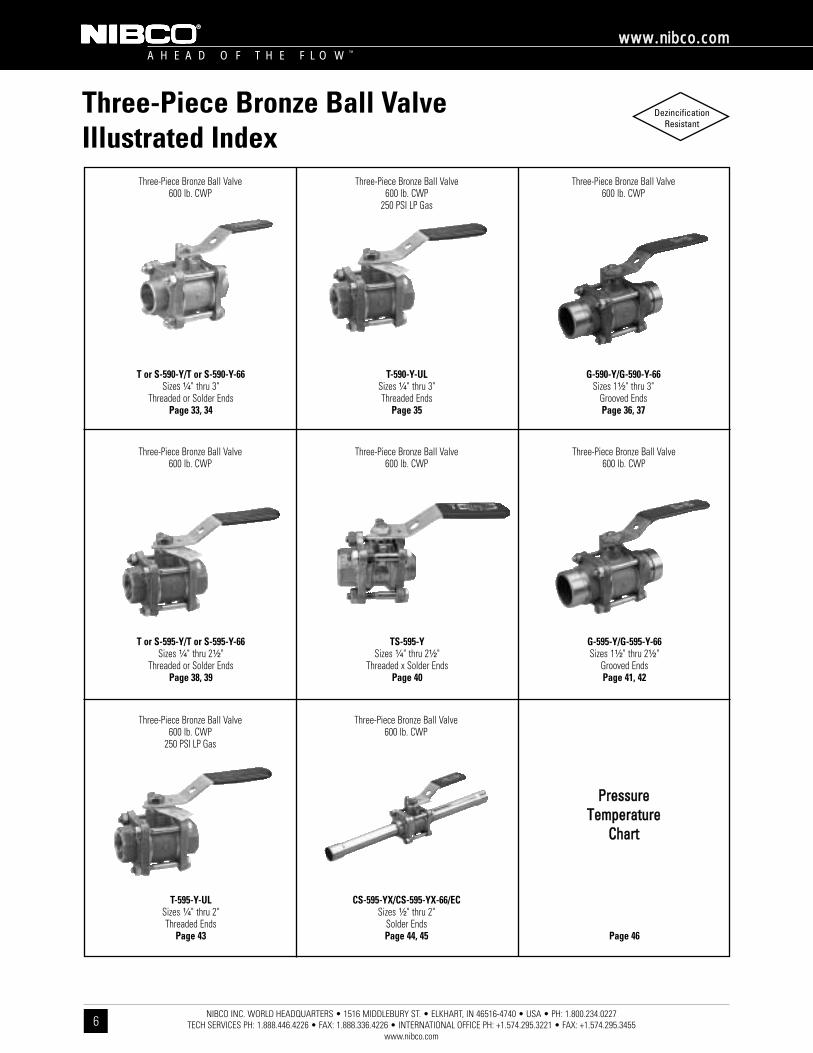
Three-Piece Bronze Ball ValveIllustrated Index
Three-Piece Bronze Ball Valve600 lb. CWP
Three-Piece Bronze Ball Valve600 lb. CWP
250 PSI LP Gas
T or S-590-Y/T or S-590-Y-66Sizes ¹⁄₄" thru 3"
Threaded or Solder EndsPage 33, 34
Three-Piece Bronze Ball Valve600 lb. CWP
T or S-595-Y/T or S-595-Y-66Sizes ¹⁄₄" thru 2¹⁄₂"
Threaded or Solder EndsPage 38, 39
Three-Piece Bronze Ball Valve600 lb. CWP
250 PSI LP Gas
T-595-Y-ULSizes ¹⁄₄" thru 2"Threaded Ends
Page 43
Three-Piece Bronze Ball Valve600 lb. CWP
CS-595-YX/CS-595-YX-66/ECSizes ¹⁄₂" thru 2"
Solder EndsPage 44, 45
PPrreessssuurree TTeemmppeerraattuurree
CChhaarrtt
Page 46
Three-Piece Bronze Ball Valve600 lb. CWP
TS-595-YSizes ¹⁄₄" thru 2¹⁄₂"
Threaded x Solder EndsPage 40
Three-Piece Bronze Ball Valve600 lb. CWP
G-595-Y/G-595-Y-66Sizes 1¹⁄₂" thru 2¹⁄₂"
Grooved EndsPage 41, 42
T-590-Y-ULSizes ¹⁄₄" thru 3"Threaded Ends
Page 35
Three-Piece Bronze Ball Valve600 lb. CWP
G-590-Y/G-590-Y-66Sizes 1¹⁄₂" thru 3"
Grooved EndsPage 36, 37

NIBCO INC. WORLD HEADQUARTERS • 1516 MIDDLEBURY ST. • ELKHART, IN 46516-4740 • USA • PH: 1.800.234.0227 TECH SERVICES PH: 1.888.446.4226 • FAX: 1.888.336.4226 • INTERNATIONAL OFFICE PH: +1.574.295.3221 • FAX: +1.574.295.3455
www.nibco.com
A H E A D O F T H E F L O W ™
wwwwww..nniibbccoo..ccoomm
7
DezincificationResistant
Bronze Ball ValvesOne-Piece Body • Reduced Port • Bronze Trim • Blowout-Proof Stem
600 PSI/41.4 Bar Non-Shock Cold Working Pressure
CONFORMS TO MSS SP-110
T-560-BR-*-20Threaded
MATERIAL LISTPART SPECIFICATION
1. Handle Nut Zinc Plated Steel2. Identification Plate Aluminum3. Handle Zinc Plated Steel Clear Chromate
Plastisol Coated4. 1Packing Nut Stainless Steel5. Belleville Washer Zinc Plated Steel6. Travel Stop Zinc Dichromate Plated Steel7. Pack Gland Brass ASTM B 16 Alloy C360008. Packing Reinforced TFE9. Grounding Washer Stainless Steel ASTM A 240 Type 304
10. Thrust Washer Reinforced TFE11. Stem Bronze ASTM B 371 Alloy C6940012. Ball Brass ASTM B 124 Alloy C37700
or ASTM B 16 Alloy C3600013. Seat Ring (2) *TFE (Y) or Reinforced TFE (R)14. Body Insert Bronze ASTM B 584 Alloy C8440015. Body Bronze ASTM B 584 Alloy C8440016. Body End Piece Brass ASTM B 16 Alloy C36000 (not shown)
¹⁄₄ and ³⁄₈ size only 1 ¹⁄₄"-³⁄₄" ASTM A 582 Type 416. 1"-2" 300 Series.
�� For detailed Operating Pressure, refer to Pressure TemperatureChart on page 46.
DIMENSIONS—WEIGHTS—QUANTITIESDimensions
Size A B C D E F G T-560-BR-*-20 MasterIn. mm. In. mm. In. mm. In. mm. In. mm. In. mm. In. mm. In. Lbs. Kg. Ctn. Qty¹⁄₄ 8 2.63 67 1.34 34 1.63 41 .38 10 4.00 102 1.22 31 10-24 .66 .30 50³⁄₈ 10 2.63 67 1.34 34 1.63 41 .38 10 4.00 102 1.22 31 10-24 .63 .28 50¹⁄₂ 15 2.63 67 1.34 34 1.63 41 .38 10 4.00 102 1.22 31 10-24 .59 .27 50³⁄₄ 20 2.88 73 1.50 38 1.71 43 .50 13 4.00 102 1.22 31 10-24 .82 .37 50
1 25 3.31 84 1.71 43 2.00 51 .63 16 4.69 119 1.34 34 ¹⁄₄-20 1.36 .62 401 ¹⁄₄ 32 3.84 98 1.97 50 2.06 52 .81 21 4.69 119 1.50 38 ¹⁄₄-20 2.01 .91 201 ¹⁄₂ 40 4.03 102 2.03 52 2.56 65 1.00 25 6.75 171 1.63 41 ¹⁄₄-20 2.75 1.25 202 50 4.59 117 2.28 58 2.75 70 1.25 32 6.75 171 2.06 52 ¹⁄₄-20 4.16 1.89 10Note: G Holes are only tapped for actuated valves.
T-560-BR-*-20NPT x NPT

NIBCO INC. WORLD HEADQUARTERS • 1516 MIDDLEBURY ST. • ELKHART, IN 46516-4740 • USA • PH: 1.800.234.0227 TECH SERVICES PH: 1.888.446.4226 • FAX: 1.888.336.4226 • INTERNATIONAL OFFICE PH: +1.574.295.3221 • FAX: +1.574.295.3455
www.nibco.com
A H E A D O F T H E F L O W ™
wwwwww..nniibbccoo..ccoomm
8
DezincificationResistant
Bronze Ball ValvesOne-Piece Body • Reduced Port • Stainless Trim • Vented Ball •Blowout-Proof Stem
600 PSI/41.4 Bar Non-Shock Cold Working Pressure
CONFORMS TO MSS SP-110
T-560-BR-*-66Threaded
MATERIAL LISTPART SPECIFICATION
1. Handle Nut Stainless Steel 300 Series2. Identification Plate Aluminum3. Handle Zinc Plated Steel Clear Chromate
Plastisol Coated4. 1Packing Nut Stainless Steel5. Belleville Washer Zinc Plated Steel6. Travel Stop Zinc Dichromate Plated Steel7. Pack Gland Stainless Steel ASTM A 276 Type 3168. Packing Reinforced TFE9. Grounding Washer Stainless Steel ASTM A 240 Type 304
10. Thrust Washer Reinforced TFE11. Stem Stainless Steel ASTM A 276 Type 31612. Ball (Vented) Stainless Steel ASTM A 276 Type 316
or ASTM A 351 Type CF8M13. Seat Ring (2) *TFE (Y) or Reinforced TFE (R)14. Body Insert Bronze ASTM B 584 Alloy C8440015. Body Bronze ASTM B 584 Alloy C8440016. Body End Piece Brass ASTM B 16 Alloy C36000 (not shown)
¹⁄₄ and ³⁄₈ size only 1 ¹⁄₄"-³⁄₄" ASTM A 582 Type 416. 1"-2" 300 Series.
�� For detailed Operating Pressure, refer to Pressure TemperatureChart on page 46.
DIMENSIONS—WEIGHTS—QUANTITIESDimensions
Size A B C D E F G T-560-BR-*-66 MasterIn. mm. In. mm. In. mm. In. mm. In. mm. In. mm. In. mm. In. Lbs. Kg.¹⁄₄ 8 2.63 67 1.34 34 1.63 41 .38 10 4.00 102 1.22 31 10-24 .66 .30 50³⁄₈ 10 2.63 67 1.34 34 1.63 41 .38 10 4.00 102 1.22 31 10-24 .63 .29 50¹⁄₂ 15 2.63 67 1.34 34 1.63 41 .38 10 4.00 102 1.22 31 10-24 .59 .27 50³⁄₄ 20 2.88 73 1.50 38 1.71 43 .50 13 4.00 102 1.22 31 10-24 .82 .37 50
1 25 3.31 84 1.71 43 2.00 51 .63 16 4.69 119 1.34 34 ¹⁄₄-20 1.36 .62 401 ¹⁄₄ 32 3.84 98 1.97 50 2.06 52 .81 21 4.69 119 1.50 38 ¹⁄₄-20 2.01 .91 201 ¹⁄₂ 40 4.03 102 2.03 52 2.56 65 1.00 25 6.75 171 1.63 41 ¹⁄₄-20 2.75 1.25 202 50 4.59 117 2.28 58 2.75 70 1.25 32 6.75 171 2.06 52 ¹⁄₄-20 4.16 1.89 10Note: G Holes are only tapped for actuated valves.
T-560-BR-*-66NPT x NPT
Ctn. Qty.

NIBCO INC. WORLD HEADQUARTERS • 1516 MIDDLEBURY ST. • ELKHART, IN 46516-4740 • USA • PH: 1.800.234.0227 TECH SERVICES PH: 1.888.446.4226 • FAX: 1.888.336.4226 • INTERNATIONAL OFFICE PH: +1.574.295.3221 • FAX: +1.574.295.3455
www.nibco.com
A H E A D O F T H E F L O W ™
wwwwww..nniibbccoo..ccoomm
9
DezincificationResistant
Bronze Ball ValvesTwo-Piece Body • Full Port ¹⁄₄"-1" • Conventional Port 1¹⁄₄"-3" •Bronze Trim • Blowout-Proof Stem
600 PSI/41.4 Bar Non-Shock Cold Working Pressure150 PSI/10.3 Bar Saturated Steam��
CONFORMS TO MSS SP-110
T-580-70Threaded
S-580-70Solder
MATERIAL LISTPART SPECIFICATION
1. Handle Nut Zinc Plated Steel2. Handle Zinc Plated Steel Clear Chromate
Plastisol Coated3. Threaded Pack Gland Brass ASTM B 16 Alloy C360004. Packing TFE5. Stem Silicon Bronze ASTM B 371 Alloy C69400
or ASTM B 99 Alloy C651006. Thrust Washer Reinforced TFE7. Ball Brass ASTM B 124 Alloy C37700 or ASTM
B16 Alloy C36000 with Hard Chrome Plate8. Seat Ring (2) Reinforced TFE9. Body Cast Red Bronze ASTM B 584 Alloy C84400
10. Body End Piece Cast Red Bronze ASTM B 584 Alloy C84400¹⁄₄" and ³⁄₈" sizes have a 304 stainless steel grounding washer.
�� For detailed Operating Pressure, refer to Pressure TemperatureChart on page 46.
DIMENSIONS—WEIGHTS—QUANTITIESDimensions
T-580-70 S-580-70 T-580-70 S-580-70Size A A B C C D T-580-70 S-580-70 Master
In. mm. In. mm. In. mm. In. mm. In. mm. In. mm. In. mm. Lbs. Kg. Lbs. Kg. Ctn. Qty.† ¹⁄₄ 8 2.00 51 1.75 44 1.75 44 5.00 127 4.75 121 .38 10 .45 .21 .42 .19 100† ³⁄₈ 10 2.00 51 1.84 47 1.75 44 5.00 127 4.81 122 .38 10 .45 .21 .42 .19 100† ¹⁄₂ 15 2.44 62 2.56 65 1.88 48 5.19 132 5.25 133 .50 13 .64 .29 .60 .27 100† ³⁄₄ 20 2.94 75 3.25 83 2.25 57 6.25 159 6.25 159 .75 19 1.33 .60 1.27 .58 50†1 25 3.34 85 3.75 95 2.38 60 6.44 164 6.63 168 1.00 25 1.79 .81 1.72 .78 401 ¹⁄₄ 32 3.94 100 4.00 102 2.63 67 6.75 171 6.75 171 1.00 25 2.17 .98 1.78 .81 201 ¹⁄₂ 40 4.31 109 4.44 113 3.00 76 8.88 226 9.00 229 1.25 32 3.27 1.48 2.87 1.30 202 50 4.63 118 5.50 140 3.16 80 9.06 230 9.50 241 1.50 38 5.09 2.31 4.60 2.08 102 ¹⁄₂ 65 5.84 148 7.28 185 3.50 89 9.66 245 10.38 264 2.00 51 8.25 3.74 8.18 3.71 63 80 7.09 180 8.78 223 4.41 112 11.53 293 12.38 314 2.50 64 15.65 7.10 14.86 6.74 4
† NIBCO supplies Full Port T or S-585-70 on this size.
Note: Solder end is designed to be soft-soldered into lines using solders with the melting point not exceeding 500°F. Higher temperature solders will damage the seat material. See installation sheet packaged with valves.
T-580-70NPT x NPT
S-580-70C x C

NIBCO INC. WORLD HEADQUARTERS • 1516 MIDDLEBURY ST. • ELKHART, IN 46516-4740 • USA • PH: 1.800.234.0227 TECH SERVICES PH: 1.888.446.4226 • FAX: 1.888.336.4226 • INTERNATIONAL OFFICE PH: +1.574.295.3221 • FAX: +1.574.295.3455
www.nibco.com
A H E A D O F T H E F L O W ™
wwwwww..nniibbccoo..ccoomm
10
DezincificationResistant
Bronze Ball ValvesTwo-Piece Body • Full Port ¹⁄₄"-1" • Conventional Port 1¹⁄₄"-3" •Stainless Trim • Blowout-Proof Stem • Vented Ball
600 PSI/41.4 Bar Non-Shock Cold Working Pressure150 PSI/10.3 Bar Saturated Steam��
CONFORMS TO MSS SP-110T-580-70-66
Threaded
S-580-70-66Solder
MATERIAL LISTPART SPECIFICATION
1. Handle Nut Stainless Steel 300 Series2. Handle Zinc Plated Steel Clear Chromate
Plastisol Coated3. Threaded Pack Gland Brass ASTM B 16 Alloy C360004. Packing TFE5. Stem Stainless Steel ASTM A 276 Type 3166. Thrust Washer Reinforced TFE7. Ball (Vented) Stainless Steel ASTM A 276 Type 316
or ASTM A 351 Type CF8M8. Seat Ring (2) Reinforced TFE9. Body Bronze ASTM B 584 Alloy C84400
10. Body End Piece Bronze ASTM B 584 Alloy C84400¹⁄₄" and ³⁄₈" sizes have a 304 stainless steel grounding washer.
�� For detailed Operating Pressure, refer to Pressure TemperatureChart on page 46.
DIMENSIONS—WEIGHTS—QUANTITIESDimensions
T-580-70-66 S-580-70-66 T-580-70-66 S-580-70-66Size A A B C C D T-580-70-66 S-580-70-66 Master
In. mm. In. mm. In. mm. In. mm. In. mm. In. mm. In. mm. Lbs. Kg. Lbs. Kg. Ctn. Qty.† ¹⁄₄ 8 2.00 51 1.75 44 1.75 44 5.00 127 4.75 121 .38 10 .45 .21 .42 .19 100† ³⁄₈ 10 2.00 51 1.84 47 1.75 44 5.00 127 4.81 122 .38 10 .45 .21 .42 .19 100† ¹⁄₂ 15 2.44 62 2.56 65 1.88 48 5.19 132 5.25 133 .50 13 .64 .29 .60 .27 100† ³⁄₄ 20 2.94 75 3.25 83 2.25 57 6.25 159 6.25 159 .75 19 1.33 .60 1.27 .58 50
†1 25 3.34 85 3.75 95 2.38 60 6.44 164 6.63 168 1.00 25 1.79 .81 1.72 .78 401 ¹⁄₄ 32 3.94 100 4.00 102 2.63 67 6.75 171 6.75 171 1.00 25 2.33 1.06 1.94 .88 201 ¹⁄₂ 40 4.31 109 4.44 113 3.00 76 8.88 226 9.00 229 1.25 32 3.49 1.58 3.10 1.40 202 50 4.63 118 5.50 140 3.16 80 9.06 230 9.50 241 1.50 38 5.16 2.34 4.67 2.12 102 ¹⁄₂ 65 5.84 148 7.28 185 3.50 89 9.66 245 10.38 264 2.00 51 8.98 4.07 8.92 4.04 63 80 7.09 180 8.78 223 4.41 112 11.53 293 12.38 314 2.50 64 17.38 7.88 16.59 7.52 4
† NIBCO supplies Full Port T or S-585-70-66 on this size.
Note: Solder end is designed to be soft-soldered into lines using solders with the melting point not exceeding 500°F. Higher temperature solders will damage the seat material. See installation sheet packaged with valves.
T-580-70-66NPT x NPT
S-580-70-66C x C
NIBCO INC. WORLD HEADQUARTERS • 1516 MIDDLEBURY ST. • ELKHART, IN 46516-4740 • USA • PH: 1.800.234.0227 TECH SERVICES PH: 1.888.446.4226 • FAX: 1.888.336.4226 • INTERNATIONAL OFFICE PH: +1.574.295.3221 • FAX: +1.574.295.3455
www.nibco.com
A H E A D O F T H E F L O W ™
wwwwww..nniibbccoo..ccoomm
11
DezincificationResistant
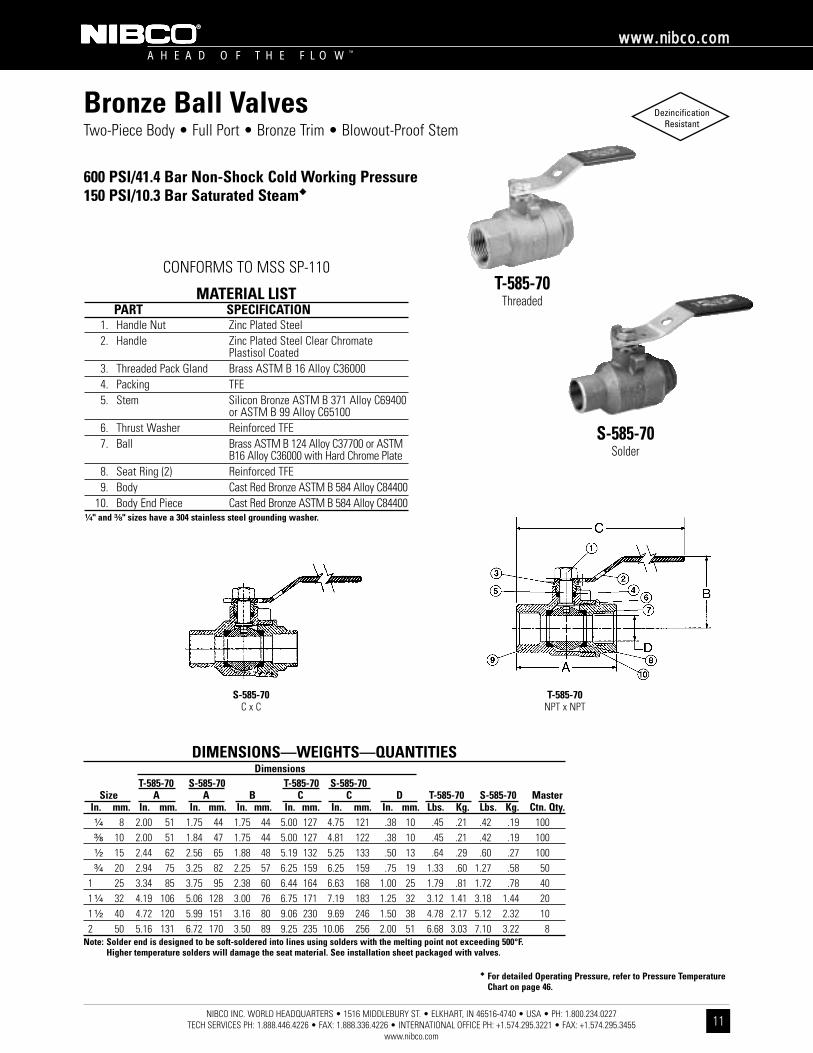
Bronze Ball ValvesTwo-Piece Body • Full Port • Bronze Trim • Blowout-Proof Stem
600 PSI/41.4 Bar Non-Shock Cold Working Pressure150 PSI/10.3 Bar Saturated Steam��
CONFORMS TO MSS SP-110T-585-70
Threaded
S-585-70Solder
MATERIAL LISTPART SPECIFICATION
1. Handle Nut Zinc Plated Steel2. Handle Zinc Plated Steel Clear Chromate
Plastisol Coated3. Threaded Pack Gland Brass ASTM B 16 Alloy C360004. Packing TFE5. Stem Silicon Bronze ASTM B 371 Alloy C69400
or ASTM B 99 Alloy C651006. Thrust Washer Reinforced TFE7. Ball Brass ASTM B 124 Alloy C37700 or ASTM
B16 Alloy C36000 with Hard Chrome Plate8. Seat Ring (2) Reinforced TFE9. Body Cast Red Bronze ASTM B 584 Alloy C84400
10. Body End Piece Cast Red Bronze ASTM B 584 Alloy C84400¹⁄₄" and ³⁄₈" sizes have a 304 stainless steel grounding washer.
�� For detailed Operating Pressure, refer to Pressure TemperatureChart on page 46.
DIMENSIONS—WEIGHTS—QUANTITIESDimensions
T-585-70 S-585-70 T-585-70 S-585-70Size A A B C C D T-585-70 S-585-70 Master
In. mm. In. mm. In. mm. In. mm. In. mm. In. mm. In. mm. Lbs. Kg. Lbs. Kg. Ctn. Qty.¹⁄₄ 8 2.00 51 1.75 44 1.75 44 5.00 127 4.75 121 .38 10 .45 .21 .42 .19 100³⁄₈ 10 2.00 51 1.84 47 1.75 44 5.00 127 4.81 122 .38 10 .45 .21 .42 .19 100¹⁄₂ 15 2.44 62 2.56 65 1.88 48 5.19 132 5.25 133 .50 13 .64 .29 .60 .27 100³⁄₄ 20 2.94 75 3.25 82 2.25 57 6.25 159 6.25 159 .75 19 1.33 .60 1.27 .58 50
1 25 3.34 85 3.75 95 2.38 60 6.44 164 6.63 168 1.00 25 1.79 .81 1.72 .78 401 ¹⁄₄ 32 4.19 106 5.06 128 3.00 76 6.75 171 7.19 183 1.25 32 3.12 1.41 3.18 1.44 201 ¹⁄₂ 40 4.72 120 5.99 151 3.16 80 9.06 230 9.69 246 1.50 38 4.78 2.17 5.12 2.32 102 50 5.16 131 6.72 170 3.50 89 9.25 235 10.06 256 2.00 51 6.68 3.03 7.10 3.22 8
Note: Solder end is designed to be soft-soldered into lines using solders with the melting point not exceeding 500°F. Higher temperature solders will damage the seat material. See installation sheet packaged with valves.
T-585-70NPT x NPT
S-585-70C x C
A H E A D O F T H E F L O W ™
wwwwww..nniibbccoo..ccoomm
12NIBCO INC. WORLD HEADQUARTERS • 1516 MIDDLEBURY ST. • ELKHART, IN 46516-4740 • USA • PH: 1.800.234.0227
TECH SERVICES PH: 1.888.446.4226 • FAX: 1.888.336.4226 • INTERNATIONAL OFFICE PH: +1.574.295.3221 • FAX: +1.574.295.3455www.nibco.com
DezincificationResistant
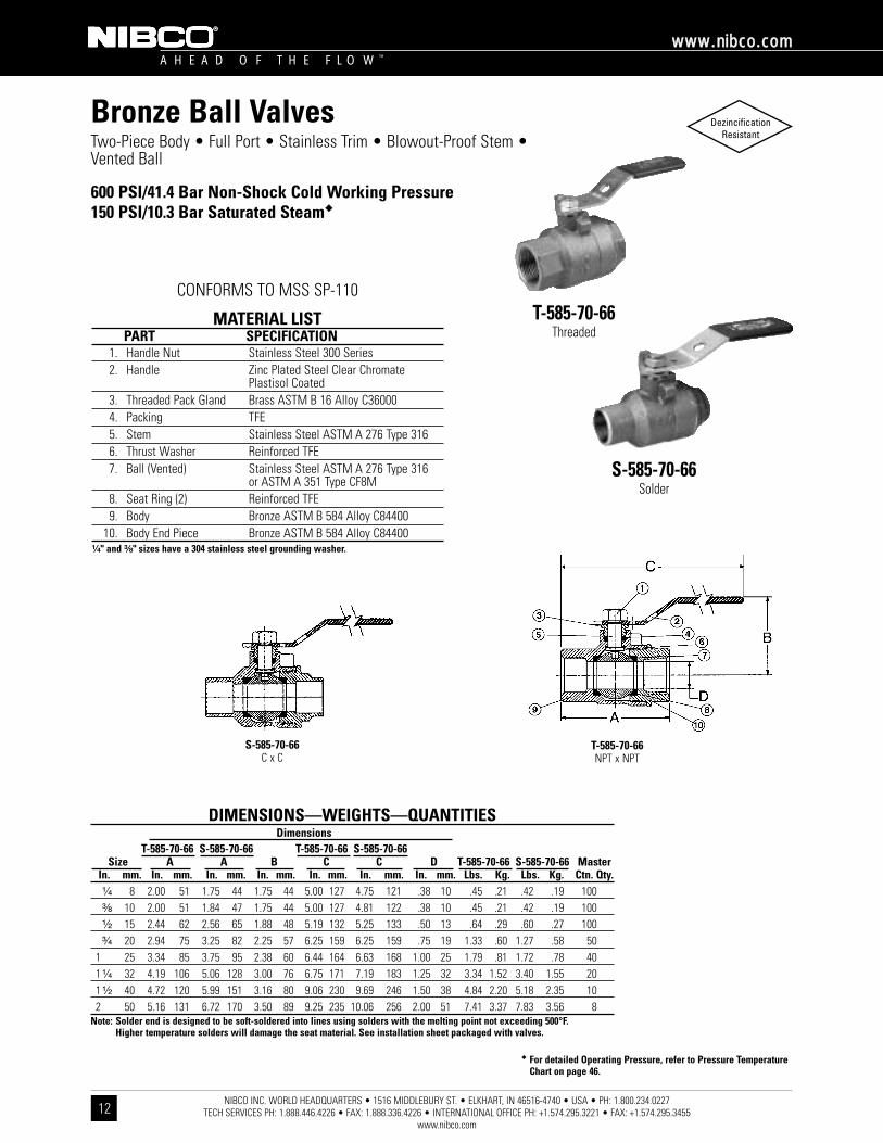
Bronze Ball ValvesTwo-Piece Body • Full Port • Stainless Trim • Blowout-Proof Stem •Vented Ball
600 PSI/41.4 Bar Non-Shock Cold Working Pressure150 PSI/10.3 Bar Saturated Steam��
CONFORMS TO MSS SP-110T-585-70-66
Threaded
S-585-70-66Solder
MATERIAL LISTPART SPECIFICATION
1. Handle Nut Stainless Steel 300 Series2. Handle Zinc Plated Steel Clear Chromate
Plastisol Coated3. Threaded Pack Gland Brass ASTM B 16 Alloy C360004. Packing TFE5. Stem Stainless Steel ASTM A 276 Type 3166. Thrust Washer Reinforced TFE7. Ball (Vented) Stainless Steel ASTM A 276 Type 316
or ASTM A 351 Type CF8M8. Seat Ring (2) Reinforced TFE9. Body Bronze ASTM B 584 Alloy C84400
10. Body End Piece Bronze ASTM B 584 Alloy C84400¹⁄₄" and ³⁄₈" sizes have a 304 stainless steel grounding washer.
�� For detailed Operating Pressure, refer to Pressure TemperatureChart on page 46.
DIMENSIONS—WEIGHTS—QUANTITIESDimensions
T-585-70-66 S-585-70-66 T-585-70-66 S-585-70-66Size A A B C C D T-585-70-66 S-585-70-66 Master
In. mm. In. mm. In. mm. In. mm. In. mm. In. mm. In. mm. Lbs. Kg. Lbs. Kg. Ctn. Qty.¹⁄₄ 8 2.00 51 1.75 44 1.75 44 5.00 127 4.75 121 .38 10 .45 .21 .42 .19 100³⁄₈ 10 2.00 51 1.84 47 1.75 44 5.00 127 4.81 122 .38 10 .45 .21 .42 .19 100¹⁄₂ 15 2.44 62 2.56 65 1.88 48 5.19 132 5.25 133 .50 13 .64 .29 .60 .27 100³⁄₄ 20 2.94 75 3.25 82 2.25 57 6.25 159 6.25 159 .75 19 1.33 .60 1.27 .58 50
1 25 3.34 85 3.75 95 2.38 60 6.44 164 6.63 168 1.00 25 1.79 .81 1.72 .78 401 ¹⁄₄ 32 4.19 106 5.06 128 3.00 76 6.75 171 7.19 183 1.25 32 3.34 1.52 3.40 1.55 201 ¹⁄₂ 40 4.72 120 5.99 151 3.16 80 9.06 230 9.69 246 1.50 38 4.84 2.20 5.18 2.35 102 50 5.16 131 6.72 170 3.50 89 9.25 235 10.06 256 2.00 51 7.41 3.37 7.83 3.56 8
Note: Solder end is designed to be soft-soldered into lines using solders with the melting point not exceeding 500°F. Higher temperature solders will damage the seat material. See installation sheet packaged with valves.
S-585-70-66C x C
T-585-70-66NPT x NPT
NIBCO INC. WORLD HEADQUARTERS • 1516 MIDDLEBURY ST. • ELKHART, IN 46516-4740 • USA • PH: 1.800.234.0227 TECH SERVICES PH: 1.888.446.4226 • FAX: 1.888.336.4226 • INTERNATIONAL OFFICE PH: +1.574.295.3221 • FAX: +1.574.295.3455
www.nibco.com
A H E A D O F T H E F L O W ™
wwwwww..nniibbccoo..ccoomm
13
DezincificationResistant
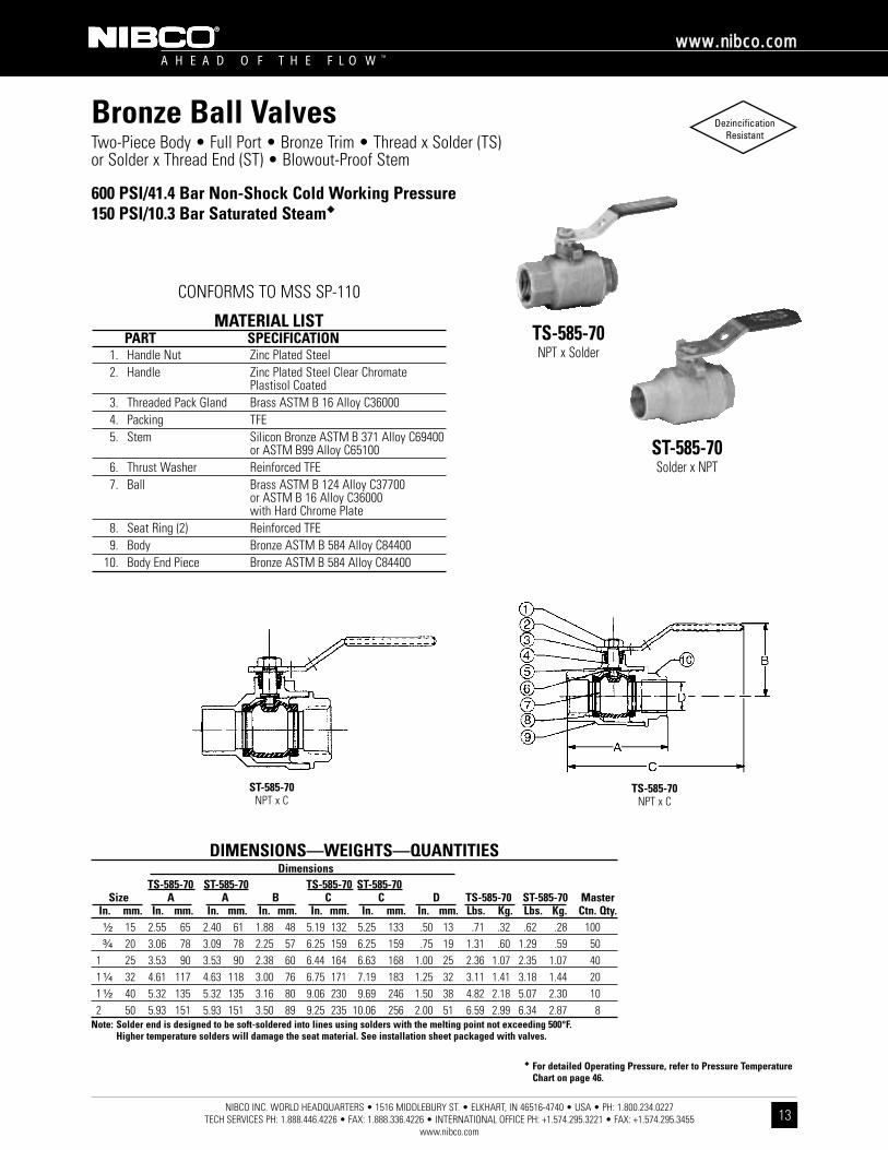
Bronze Ball ValvesTwo-Piece Body • Full Port • Bronze Trim • Thread x Solder (TS) or Solder x Thread End (ST) • Blowout-Proof Stem
600 PSI/41.4 Bar Non-Shock Cold Working Pressure150 PSI/10.3 Bar Saturated Steam��
CONFORMS TO MSS SP-110
TS-585-70NPT x Solder
ST-585-70Solder x NPT
MATERIAL LISTPART SPECIFICATION
1. Handle Nut Zinc Plated Steel2. Handle Zinc Plated Steel Clear Chromate
Plastisol Coated3. Threaded Pack Gland Brass ASTM B 16 Alloy C360004. Packing TFE5. Stem Silicon Bronze ASTM B 371 Alloy C69400
or ASTM B99 Alloy C651006. Thrust Washer Reinforced TFE7. Ball Brass ASTM B 124 Alloy C37700
or ASTM B 16 Alloy C36000 with Hard Chrome Plate
8. Seat Ring (2) Reinforced TFE9. Body Bronze ASTM B 584 Alloy C84400
10. Body End Piece Bronze ASTM B 584 Alloy C84400
�� For detailed Operating Pressure, refer to Pressure TemperatureChart on page 46.
DIMENSIONS—WEIGHTS—QUANTITIESDimensions
TS-585-70 ST-585-70 TS-585-70 ST-585-70Size A A B C C D TS-585-70 ST-585-70 Master
In. mm. In. mm. In. mm. In. mm. In. mm. In. mm. In. mm. Lbs. Kg. Lbs. Kg. Ctn. Qty.¹⁄₂ 15 2.55 65 2.40 61 1.88 48 5.19 132 5.25 133 .50 13 .71 .32 .62 .28 100³⁄₄ 20 3.06 78 3.09 78 2.25 57 6.25 159 6.25 159 .75 19 1.31 .60 1.29 .59 50
1 25 3.53 90 3.53 90 2.38 60 6.44 164 6.63 168 1.00 25 2.36 1.07 2.35 1.07 401 ¹⁄₄ 32 4.61 117 4.63 118 3.00 76 6.75 171 7.19 183 1.25 32 3.11 1.41 3.18 1.44 201 ¹⁄₂ 40 5.32 135 5.32 135 3.16 80 9.06 230 9.69 246 1.50 38 4.82 2.18 5.07 2.30 102 50 5.93 151 5.93 151 3.50 89 9.25 235 10.06 256 2.00 51 6.59 2.99 6.34 2.87 8
Note: Solder end is designed to be soft-soldered into lines using solders with the melting point not exceeding 500°F. Higher temperature solders will damage the seat material. See installation sheet packaged with valves.
TS-585-70NPT x C
ST-585-70NPT x C

NIBCO INC. WORLD HEADQUARTERS • 1516 MIDDLEBURY ST. • ELKHART, IN 46516-4740 • USA • PH: 1.800.234.0227 TECH SERVICES PH: 1.888.446.4226 • FAX: 1.888.336.4226 • INTERNATIONAL OFFICE PH: +1.574.295.3221 • FAX: +1.574.295.3455
www.nibco.com
A H E A D O F T H E F L O W ™
wwwwww..nniibbccoo..ccoomm
14
DezincificationResistant
Bronze Ball ValvesTwo-Piece Body • Full Port • Bronze Trim • Male x Female Thread Ends •Blowout-Proof Stem
600 PSI/41.4 Bar Non-Shock Cold Working Pressure150 PSI/10.3 Bar Saturated Steam��
CONFORMS TO MSS SP-110
MTT-585-70Male x Female NPT
MATERIAL LISTPART SPECIFICATION
1. Handle Nut Zinc Plated Steel2. Handle Zinc Plated Steel Clear Chromate
Plastisol Coated3. Threaded Pack Gland Brass ASTM B 16 Alloy C360004. Packing TFE5. Thrust Washer Reinforced TFE6. Stem Silicon Bronze ASTM B 371 Alloy C69400
or ASTM B 99 Alloy C651007. Ball Brass ASTM B 124 Alloy C37700 or
ASTM B 16 Alloy C36000 with Hard Chrome Plate
8. Seat Ring (2) Reinforced TFE9. Body Bronze ASTM B 584 Alloy C84400
10. Male Body End Brass ASTM B 16 Alloy C3600011. Cap Plug Low Density Polyethylene
�� For detailed Operating Pressure, refer to Pressure TemperatureChart on page 46.
DIMENSIONS—WEIGHTS—QUANTITIESDimensions
Size A B C D MTT-585-70 MasterIn. mm. In. mm. In. mm. In. mm. In. mm. Lbs. Kg. Ctn. Qty.¹⁄₄ 8 2.41 61 5.30 135 1.75 44 .38 10 .43 .19 40³⁄₈ 10 2.40 61 5.30 135 1.72 44 .38 10 .52 .24 40¹⁄₂ 15 2.80 71 5.50 140 1.88 48 .50 13 .78 .35 40³⁄₄ 20 3.40 86 6.59 167 2.25 57 .75 19 1.54 .70 20
1 25 4.00 102 6.99 178 2.38 60 1.00 25 2.71 1.23 201 ¹⁄₄ 32 4.58 116 9.18 233 3.00 76 1.25 32 3.56 1.62 101 ¹⁄₂ 40 5.20 132 9.53 242 3.16 80 1.50 38 5.34 2.42 62 50 5.49 139 9.61 244 3.50 89 2.00 51 6.83 3.10 4
MTT-585-70Male x Female NPT

NIBCO INC. WORLD HEADQUARTERS • 1516 MIDDLEBURY ST. • ELKHART, IN 46516-4740 • USA • PH: 1.800.234.0227 TECH SERVICES PH: 1.888.446.4226 • FAX: 1.888.336.4226 • INTERNATIONAL OFFICE PH: +1.574.295.3221 • FAX: +1.574.295.3455
www.nibco.com
A H E A D O F T H E F L O W ™
wwwwww..nniibbccoo..ccoomm
15
DezincificationResistant
Bronze Ball ValvesTwo-Piece Body • Full Port • Bronze Trim • Body with Chrome Plating • Blowout-Proof Stem
600 PSI/41.4 Bar Non-Shock Cold Working Pressure
CONFORMS TO MSS SP-110
T-585-70-CPThreaded
MATERIAL LISTPART SPECIFICATION
1. Handle Nut Zinc Plated Steel2. Handle Zinc Plated Steel Clear Chromate
Plastisol Coated3. Threaded Pack Gland Brass ASTM B 16 Alloy C360004. Packing TFE5. Stem Silicon Bronze ASTM B 371 Alloy C69400
or ASTM B 99 Alloy C651006. Thrust Washer Reinforced TFE7. Ball Brass ASTM B 124 Alloy C37700
or ASTM B 16 Alloy C36000with Hard Chrome Plate
8. Seat Ring (2) Reinforced TFE9. Body Chrome Plated Bronze
ASTM B 584 Alloy C8440010. Body End Piece Chrome Plated Bronze
ASTM B 584 Alloy C84400
�� For detailed Operating Pressure, refer to Pressure TemperatureChart on page 46.
DIMENSIONS—WEIGHTS—QUANTITIESDimensions
Size A B C D T-585-70-CP MasterIn. mm. In. mm. In. mm. In. mm. In. mm. Lbs. Kg. Ctn. Qty.¹⁄₄ 8 2.00 51 1.75 44 5.00 127 .38 10 .45 .21 100³⁄₈ 10 2.00 51 1.75 44 5.00 127 .38 10 .45 .20 100¹⁄₂ 15 2.44 62 1.88 48 5.19 132 .50 13 .64 .29 100³⁄₄ 20 2.94 75 2.25 57 6.25 159 .75 19 1.42 .64 50
1 25 3.34 85 2.38 60 6.44 164 1.00 25 1.79 .81 401 ¹⁄₄ 32 4.19 106 3.00 76 6.75 171 1.25 32 3.12 1.41 201 ¹⁄₂ 40 4.72 120 3.16 80 9.06 230 1.50 38 4.78 2.17 102 50 5.16 131 3.50 89 9.25 235 2.00 51 6.68 3.03 8
T-585-70-CPNPT x NPT
NIBCO INC. WORLD HEADQUARTERS • 1516 MIDDLEBURY ST. • ELKHART, IN 46516-4740 • USA • PH: 1.800.234.0227 TECH SERVICES PH: 1.888.446.4226 • FAX: 1.888.336.4226 • INTERNATIONAL OFFICE PH: +1.574.295.3221 • FAX: +1.574.295.3455
www.nibco.com
A H E A D O F T H E F L O W ™
wwwwww..nniibbccoo..ccoomm
16
DezincificationResistant
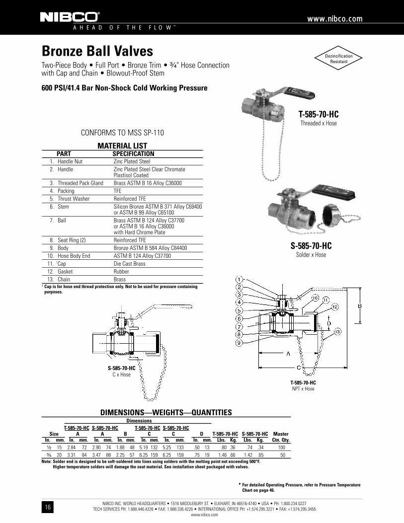
Bronze Ball ValvesTwo-Piece Body • Full Port • Bronze Trim • ³⁄₄" Hose Connection with Cap and Chain • Blowout-Proof Stem
600 PSI/41.4 Bar Non-Shock Cold Working Pressure
CONFORMS TO MSS SP-110
T-585-70-HCThreaded x Hose
S-585-70-HCSolder x Hose
MATERIAL LISTPART SPECIFICATION
1. Handle Nut Zinc Plated Steel2. Handle Zinc Plated Steel Clear Chromate
Plastisol Coated3. Threaded Pack Gland Brass ASTM B 16 Alloy C360004. Packing TFE5. Thrust Washer Reinforced TFE6. Stem Silicon Bronze ASTM B 371 Alloy C69400
or ASTM B 99 Alloy C651007. Ball Brass ASTM B 124 Alloy C37700
or ASTM B 16 Alloy C36000 with Hard Chrome Plate
8. Seat Ring (2) Reinforced TFE9. Body Bronze ASTM B 584 Alloy C84400
10. Hose Body End ASTM B 124 Alloy C3770011. 1Cap Die Cast Brass12. Gasket Rubber13. Chain Brass
1 Cap is for hose end thread protection only. Not to be used for pressure containingpurposes.
�� For detailed Operating Pressure, refer to Pressure TemperatureChart on page 46.
DIMENSIONS—WEIGHTS—QUANTITIESDimensions
T-585-70-HC S-585-70-HC T-585-70-HC S-585-70-HCSize A A B C C D T-585-70-HC S-585-70-HC Master
In. mm. In. mm. In. mm. In. mm. In. mm. In. mm. In. mm. Lbs. Kg. Lbs. Kg. Ctn. Qty.¹⁄₂ 15 2.84 72 2.90 74 1.88 48 5.19 132 5.25 133 .50 13 .80 .36 .74 .34 100³⁄₄ 20 3.31 84 3.47 88 2.25 57 6.25 159 6.25 159 .75 19 1.46 .66 1.42 .65 50
Note: Solder end is designed to be soft-soldered into lines using solders with the melting point not exceeding 500°F. Higher temperature solders will damage the seat material. See installation sheet packaged with valves.
S-585-70-HCC x Hose
T-585-70-HCNPT x Hose
DIMENSIONS—WEIGHTS—QUANTITIESDimensions
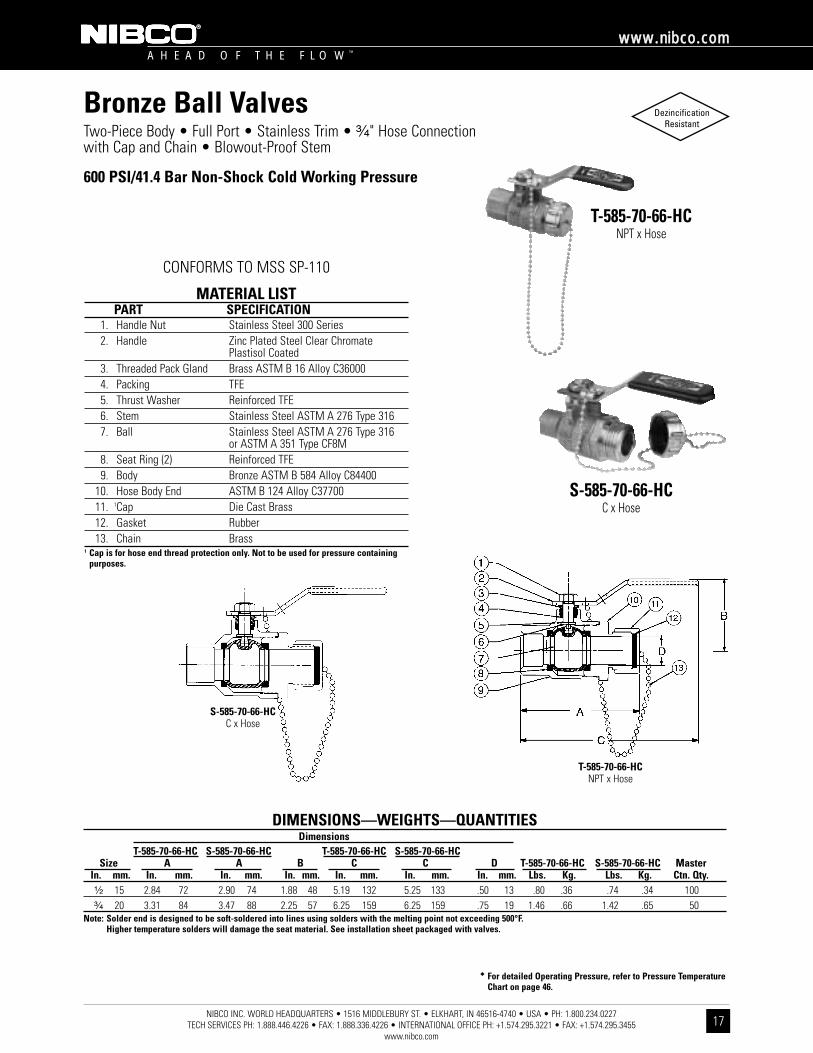
T-585-70-66-HC S-585-70-66-HC T-585-70-66-HC S-585-70-66-HCSize A A B C C D T-585-70-66-HC S-585-70-66-HC Master
In. mm. In. mm. In. mm. In. mm. In. mm. In. mm. In. mm. Lbs. Kg. Lbs. Kg. Ctn. Qty.¹⁄₂ 15 2.84 72 2.90 74 1.88 48 5.19 132 5.25 133 .50 13 .80 .36 .74 .34 100³⁄₄ 20 3.31 84 3.47 88 2.25 57 6.25 159 6.25 159 .75 19 1.46 .66 1.42 .65 50
Note: Solder end is designed to be soft-soldered into lines using solders with the melting point not exceeding 500°F. Higher temperature solders will damage the seat material. See installation sheet packaged with valves.
NIBCO INC. WORLD HEADQUARTERS • 1516 MIDDLEBURY ST. • ELKHART, IN 46516-4740 • USA • PH: 1.800.234.0227 TECH SERVICES PH: 1.888.446.4226 • FAX: 1.888.336.4226 • INTERNATIONAL OFFICE PH: +1.574.295.3221 • FAX: +1.574.295.3455
www.nibco.com
A H E A D O F T H E F L O W ™
wwwwww..nniibbccoo..ccoomm
17
DezincificationResistant
Bronze Ball ValvesTwo-Piece Body • Full Port • Stainless Trim • ³⁄₄" Hose Connection with Cap and Chain • Blowout-Proof Stem
600 PSI/41.4 Bar Non-Shock Cold Working Pressure
CONFORMS TO MSS SP-110
T-585-70-66-HCNPT x Hose
S-585-70-66-HCC x Hose
MATERIAL LISTPART SPECIFICATION
1. Handle Nut Stainless Steel 300 Series2. Handle Zinc Plated Steel Clear Chromate
Plastisol Coated3. Threaded Pack Gland Brass ASTM B 16 Alloy C360004. Packing TFE5. Thrust Washer Reinforced TFE6. Stem Stainless Steel ASTM A 276 Type 3167. Ball Stainless Steel ASTM A 276 Type 316
or ASTM A 351 Type CF8M8. Seat Ring (2) Reinforced TFE9. Body Bronze ASTM B 584 Alloy C84400
10. Hose Body End ASTM B 124 Alloy C3770011. 1Cap Die Cast Brass12. Gasket Rubber13. Chain Brass
1 Cap is for hose end thread protection only. Not to be used for pressure containingpurposes.
�� For detailed Operating Pressure, refer to Pressure TemperatureChart on page 46.
S-585-70-66-HCC x Hose
T-585-70-66-HCNPT x Hose
NIBCO INC. WORLD HEADQUARTERS • 1516 MIDDLEBURY ST. • ELKHART, IN 46516-4740 • USA • PH: 1.800.234.0227 TECH SERVICES PH: 1.888.446.4226 • FAX: 1.888.336.4226 • INTERNATIONAL OFFICE PH: +1.574.295.3221 • FAX: +1.574.295.3455
www.nibco.com
A H E A D O F T H E F L O W ™
wwwwww..nniibbccoo..ccoomm
18
DezincificationResistant
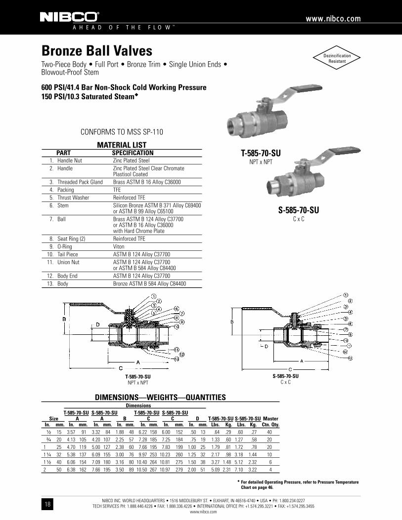
Bronze Ball ValvesTwo-Piece Body • Full Port • Bronze Trim • Single Union Ends •Blowout-Proof Stem
600 PSI/41.4 Bar Non-Shock Cold Working Pressure150 PSI/10.3 Saturated Steam��
CONFORMS TO MSS SP-110
T-585-70-SUNPT x NPT
S-585-70-SUC x C
MATERIAL LISTPART SPECIFICATION
1. Handle Nut Zinc Plated Steel2. Handle Zinc Plated Steel Clear Chromate
Plastisol Coated3. Threaded Pack Gland Brass ASTM B 16 Alloy C360004. Packing TFE5. Thrust Washer Reinforced TFE6. Stem Silicon Bronze ASTM B 371 Alloy C69400
or ASTM B 99 Alloy C651007. Ball Brass ASTM B 124 Alloy C37700
or ASTM B 16 Alloy C36000with Hard Chrome Plate
8. Seat Ring (2) Reinforced TFE9. O-Ring Viton
10. Tail Piece ASTM B 124 Alloy C3770011. Union Nut ASTM B 124 Alloy C37700
or ASTM B 584 Alloy C8440012. Body End ASTM B 124 Alloy C3770013. Body Bronze ASTM B 584 Alloy C84400
�� For detailed Operating Pressure, refer to Pressure TemperatureChart on page 46.
DIMENSIONS—WEIGHTS—QUANTITIESDimensions
T-585-70-SU S-585-70-SU T-585-70-SU S-585-70-SUSize A A B C C D T-585-70-SU S-585-70-SU Master
In. mm. In. mm. In. mm. In. mm. In. mm. In. mm. In. mm. Lbs. Kg. Lbs. Kg. Ctn. Qty.¹⁄₂ 15 3.57 91 3.32 84 1.88 48 6.22 158 6.00 152 .50 13 .64 .29 .60 .27 40³⁄₄ 20 4.13 105 4.20 107 2.25 57 7.28 185 7.25 184 .75 19 1.33 .60 1.27 .58 20
1 25 4.70 119 5.00 127 2.38 60 7.66 195 7.83 199 1.00 25 1.79 .81 1.72 .78 201 ¹⁄₄ 32 5.38 137 6.09 155 3.00 76 9.97 253 10.23 260 1.25 32 2.17 .98 3.18 1.44 101 ¹⁄₂ 40 6.06 154 7.09 180 3.16 80 10.40 264 10.81 275 1.50 38 3.27 1.48 5.12 2.32 62 50 6.38 162 7.66 195 3.50 89 10.50 267 10.97 279 2.00 51 5.09 2.31 7.10 3.22 4
S-585-70-SUC x C
T-585-70-SUNPT x NPT

NIBCO INC. WORLD HEADQUARTERS • 1516 MIDDLEBURY ST. • ELKHART, IN 46516-4740 • USA • PH: 1.800.234.0227 TECH SERVICES PH: 1.888.446.4226 • FAX: 1.888.336.4226 • INTERNATIONAL OFFICE PH: +1.574.295.3221 • FAX: +1.574.295.3455
www.nibco.com
A H E A D O F T H E F L O W ™
wwwwww..nniibbccoo..ccoomm
19
DezincificationResistant
Bronze Ball ValvesTwo-Piece Body • Full Port • Bronze Trim • Single Union Ends •Blowout-Proof Stem
600 PSI/41.4 Bar Non-Shock Cold Working Pressure150 PSI/10.3 Bar Saturated Steam��
CONFORMS TO MSS SP-110
TS-585-70-SUThreaded x Solder
ST-585-70-SUSolder x Threaded
MATERIAL LISTPART SPECIFICATION
1. Handle Nut Zinc Plated Steel2. Handle Zinc Plated Steel Clear Chromate
Plastisol Coated3. Threaded Pack Gland Brass ASTM B 16 Alloy C360004. Packing TFE5. Thrust Washer Reinforced TFE6. Stem Silicon Bronze ASTM B 371 Alloy C69400
or ASTM B 99 Alloy C651007. Ball Brass ASTM B 124 alloy C37700
or ASTM B 16 Alloy C36000with Hard Chrome Plate
8. Seat Ring (2) Reinforced TFE9. O-Ring Viton
10. Tail Piece ASTM B 124 Alloy C3770011. Union Nut ASTM B 124 Alloy C37700
or ASTM B 584 Alloy C8440012. Body End ASTM B 124 Alloy C3770013. Body Bronze ASTM B 584 Alloy C84400
�� For detailed Operating Pressure, refer to Pressure TemperatureChart on page 46.
ST-585-70-SUC x NPT
TS-585-70-SUNPT x C
DIMENSIONS—WEIGHTS—QUANTITIESDimensions
ST-585-70-SU TS-585-70-SU ST-585-70-SU TS-585-70-SUSize A A B C C D ST-585-70-SU TS-585-70-SU Master
In. mm. In. mm. In. mm. In. mm. In. mm. In. mm. In. mm. Lbs. Kg. Lbs. Kg. Ctn. Qty.¹⁄₂ 15 3.53 90 3.21 82 1.88 48 6.22 158 6.00 152 .50 132 1.21 .55 1.21 .55 40³⁄₄ 20 4.22 107 4.10 104 2.25 57 7.28 185 7.25 184 .75 19 1.84 .84 1.84 .84 20
1 25 4.86 123 4.91 125 2.38 60 7.66 195 7.83 199 1.00 25 2.91 1.32 2.91 1.32 201 ¹⁄₄ 32 5.79 147 5.63 143 3.00 76 9.97 253 10.23 260 1.25 32 4.39 2.00 4.39 2.00 101 ¹⁄₂ 40 6.63 168 6.28 160 3.16 80 10.40 264 10.81 275 1.50 38 6.44 2.93 6.44 2.93 62 50 7.10 180 6.89 175 3.50 89 10.50 267 10.91 277 2.00 51 9.44 4.29 9.44 4.29 4

NIBCO INC. WORLD HEADQUARTERS • 1516 MIDDLEBURY ST. • ELKHART, IN 46516-4740 • USA • PH: 1.800.234.0227 TECH SERVICES PH: 1.888.446.4226 • FAX: 1.888.336.4226 • INTERNATIONAL OFFICE PH: +1.574.295.3221 • FAX: +1.574.295.3455
www.nibco.com
A H E A D O F T H E F L O W ™
wwwwww..nniibbccoo..ccoomm
20
DezincificationResistant
Bronze Ball ValvesTwo-Piece Body • 250 Steam Rating • Full Port • 316SS Trim •Carbon-Filled TFE Seats • Blowout-Proof Stem • Vented Ball
600 PSI/41.4 Bar Non-Shock Cold Working Pressure250 PSI/17.2 Bar Saturated Steam��
CONFORMS TO MSS SP-110
T-585-70-66-STThreaded
MATERIAL LISTPART SPECIFICATION
1. Handle Nut 300 Series Stainless Steel2. Handle Stainless Steel Plastisol Coated3. Threaded Pack Gland Brass ASTM B 16 Alloy C360004. Packing Carbon Filled TFE5. Thrust Washer Carbon Filled TFE6. Stem Stainless Steel ASTM A 276 Type 3167. Ball (Vented) Stainless Steel ASTM A 276 Type 316
or ASTM A 351 Type CF8M8. Seat Ring (2) Carbon Filled TFE9. Body Bronze ASTM B 61 Alloy C92200
10. Body End Piece Bronze ASTM B 584 Alloy C84400
�� For detailed Operating Pressure, refer to Pressure TemperatureChart on page 46.
DIMENSIONS—WEIGHTS—QUANTITIESDimensions
Size A B C D T-585-70-66-ST MasterIn. mm. In. mm. In. mm. In. mm. In. mm. Lbs. Kg. Ctn. Qty.¹⁄₂ 15 2.44 62 1.88 48 5.19 132 .50 13 .64 .29 10³⁄₄ 20 2.94 75 2.25 57 6.25 159 .75 19 1.33 .60 5
1 25 3.34 85 2.38 61 6.44 164 1.00 25 1.79 .81 51 ¹⁄₄ 32 4.19 106 3.00 76 6.75 171 1.25 32 2.17 .98 51 ¹⁄₂ 40 4.72 120 3.16 80 9.06 230 1.50 38 3.27 1.48 52 50 5.16 131 3.50 89 9.25 235 2.00 51 5.09 2.31 2
T-585-70-66-STNPT x NPT

NIBCO INC. WORLD HEADQUARTERS • 1516 MIDDLEBURY ST. • ELKHART, IN 46516-4740 • USA • PH: 1.800.234.0227 TECH SERVICES PH: 1.888.446.4226 • FAX: 1.888.336.4226 • INTERNATIONAL OFFICE PH: +1.574.295.3221 • FAX: +1.574.295.3455
www.nibco.com
A H E A D O F T H E F L O W ™
wwwwww..nniibbccoo..ccoomm
21
DezincificationResistant
Bronze Integral Ball Check ValvesTwo-Piece Body • Full Port • Blowout-Proof Stem
250 PSI/17.2 Bar Non-Shock Cold Working Pressure
BALL VALVECONFORMS TO MSS SP-110
T-585-70-ICThreaded
MATERIAL LISTPART SPECIFICATION
1. Handle Zinc Plated Steel Clear Chromate Plastisol Coated
2. Handle Nut Zinc Plated Steel3. Threaded Pack Gland Brass ASTM B 16 Alloy C360004. Packing TFE5. Thrust Washer Reinforced TFE6. Stem Silicon Bronze ASTM B 371 Alloy C69400
or ASTM B 99 Alloy C651007. Seat Ring (2) Reinforced TFE8. Ball Brass ASTM B 124 Alloy C37700 or ASTM
B 16 Alloy C36000 with Hard Chrome Plate9. Main Body Bronze ASTM B 584 Alloy C84400
10. Coupling ASTM B 124 Alloy C3770011. Check Valve Body Bronze ASTM B 584 Alloy C8440012. Soft Disc Buna-N13. Disc Holder Stainless Steel Type 30114. Spring Stainless Steel ASTM A 276 Type 31615. Seat Screw Stainless Steel ASTM A 276 Alloy S4300016. Valve Stem Stainless Steel ASTM A 582 Alloy C30300
Note: Buna disc installed in check valve. Maximum temperature of Buna is 180° F.
DIMENSIONS—WEIGHTS—QUANTITIESDimensions
Size A B C D T-585-70-IC MasterIn. mm. In. mm. In. mm. In. mm. In. mm. Lbs. Kg. Ctn. Qty.¹⁄₂ 15 3.85 98 1.88 48 5.19 132 .50 15 1.05 .48 40³⁄₄ 20 4.40 112 2.25 57 6.25 159 .75 20 1.76 .80 25
1 25 5.11 130 2.38 60 6.44 164 1.00 25 2.54 1.15 101 ¹⁄₄ 32 6.08 154 3.00 76 6.75 171 1.25 32 4.25 1.93 101 ¹⁄₂ 40 6.91 176 3.16 80 9.06 230 1.50 40 5.84 2.65 62 50 7.56 192 3.50 89 9.25 235 2.00 50 8.33 3.79 4
Check Valve Cracking Pressure¹⁄₂" requires 1¹⁄₂ pounds pressure to open³⁄₄" - 2" requires ¹⁄₂ pound pressure to open
T-585-70-ICNPT x NPT

NIBCO INC. WORLD HEADQUARTERS • 1516 MIDDLEBURY ST. • ELKHART, IN 46516-4740 • USA • PH: 1.800.234.0227 TECH SERVICES PH: 1.888.446.4226 • FAX: 1.888.336.4226 • INTERNATIONAL OFFICE PH: +1.574.295.3221 • FAX: +1.574.295.3455
www.nibco.com
A H E A D O F T H E F L O W ™
wwwwww..nniibbccoo..ccoomm
22
DezincificationResistant
Bronze Ball ValvesTwo-Piece Body • Full Port ¹⁄₄"-1" • Conventional Port 1¹⁄₄"-2" • Bronze Trim •Safety Vent® for Pneumatic Applications • Blowout-Proof Stem
600 PSI/41.4 Bar Non-Shock Cold Working Pressure
CONFORMS TO MSS SP-110 • O.S.H.A. 1910.147
T-585-70-SV¹⁄₄"-1" Full Port
Threaded
T-580-70-SV1¹⁄₄"-2" Conventional Port
Threaded
MATERIAL LISTPART SPECIFICATION
1. Handle Nut Zinc Plated Steel 2. Handle Zinc Plated Steel Clear Chromate
Plastisol Coated3. Threaded Pack Gland Brass ASTM B 16 Alloy C360004. Packing TFE5. Stem Silicon Bronze ASTM B 371 Alloy C69400
or ASTM B 99 Alloy C651006. Thrust Washer Reinforced TFE7. Ball Brass ASTM B 124 Alloy C37700
or ASTM B 16 Alloy C36000with Hard Chrome Plate
8. Seat Ring (2) Reinforced TFE9. Body Bronze ASTM B 584 Alloy C84400
10. Body End Piece Bronze ASTM B 584 Alloy C8440011. Locking Device 300 Series Stainless Steel
Note: A Buna O-ring is installed on the upstream side behind the seat ring.Maximum temperature of Buna is 180° F. (Not Shown)
�� For detailed Operating Pressure, refer to Pressure TemperatureChart on page 46.
DIMENSIONS—WEIGHTS—QUANTITIESDimensions T-585-70-SV
Size A B C D T-580-70-SV MasterIn. mm. In. mm. In. mm. In. mm. In. mm. Lbs. Kg. Ctn. Qty.
† ¹⁄₄ 8 2.00 51 1.75 44 5.00 127 .38 10 .49 .22 100† ³⁄₈ 10 2.00 51 1.75 44 5.00 127 .38 10 .48 .22 100† ¹⁄₂ 15 2.44 62 1.88 48 5.19 132 .50 13 .68 .31 100† ³⁄₄ 20 2.94 75 2.25 57 6.25 159 .75 19 1.38 .63 50
†1 25 3.34 85 2.38 60 6.44 164 1.00 25 1.99 .90 401 ¹⁄₄ 32 3.94 100 2.63 67 6.75 171 1.00 25 2.37 1.07 201 ¹⁄₂ 40 4.31 109 3.00 76 8.88 226 1.25 32 3.57 1.62 202 50 4.63 118 3.16 80 9.06 230 1.50 38 5.20 2.36 10NIBCO T-585-70-SV Safety Vent® lock-out ball valves provide positive energy isolationper O.S.H.A. standard 1910.147. Valves lock in closed position only. For compressed air.To order specify T-585-70-SV/T-580-70-SV.
† NIBCO Supplies Full Port T-585-70-SV on this size.
T-585-70-SVT-580-70-SVNPT x NPT
NIBCO INC. WORLD HEADQUARTERS • 1516 MIDDLEBURY ST. • ELKHART, IN 46516-4740 • USA • PH: 1.800.234.0227 TECH SERVICES PH: 1.888.446.4226 • FAX: 1.888.336.4226 • INTERNATIONAL OFFICE PH: +1.574.295.3221 • FAX: +1.574.295.3455
www.nibco.com
A H E A D O F T H E F L O W ™
wwwwww..nniibbccoo..ccoomm
DezincificationResistant
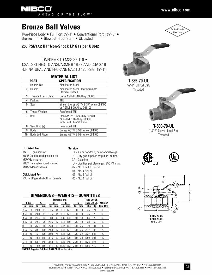
Bronze Ball ValvesTwo-Piece Body • Full Port ¹⁄₄"-1" • Conventional Port 1¹⁄₄"-3" • Bronze Trim • Blowout-Proof Stem • UL Listed
250 PSI/17.2 Bar Non-Shock LP Gas per UL842
CONFORMS TO MSS SP-110 •CSA CERTIFIED TO ANSI/ASME B 16.33 AND CGA 3.16FOR NATURAL AND PROPANE GAS TO 125 PSIG (¹⁄₄"-1")
MATERIAL LISTPART SPECIFICATION
1. Handle Nut Zinc Plated Steel2. Handle Zinc Plated Steel Clear Chromate
Plastisol Coated3. Threaded Pack Gland Brass ASTM B 16 Alloy C360004. Packing TFE5. Stem Silicon Bronze ASTM B 371 Alloy C69400
or ASTM B 99 Alloy C651006. Thrust Washer Reinforced TFE7. Ball Brass ASTM B 124 Alloy C37700
or ASTM B 16 Alloy C36000with Hard Chrome Plate
8. Seat Ring (2) Reinforced TFE9. Body Bronze ASTM B 584 Alloy C84400
10. Body End Piece Bronze ASTM B 584 Alloy C84400
23
DIMENSIONS—WEIGHTS—QUANTITIESDimensions T-585-70-UL
Size A B C D T-580-70-UL MasterIn. mm. In. mm. In. mm. In. mm. In. mm. Lbs. Kg. Ctn. Qty.†¹⁄₄ 8 2.00 51 1.75 44 5.00 127 .38 10 .45 .21 100† ³⁄₈ 10 2.00 51 1.75 44 5.00 127 .38 10 .45 .20 100† ¹⁄₂ 15 2.44 62 1.88 48 5.19 132 .50 13 .64 .29 100† ³⁄₄ 20 2.94 75 2.25 57 6.25 159 .75 19 1.33 .60 50
†1 25 3.34 85 2.38 60 6.44 164 1.00 25 1.79 .81 401 ¹⁄₄ 32 3.94 100 2.63 67 6.75 171 1.00 25 2.17 .98 201 ¹⁄₂ 40 4.31 109 3.00 76 8.88 226 1.25 32 3.27 1.48 202 50 4.63 118 3.16 80 9.06 230 1.50 38 5.09 2.31 102 ¹⁄₂ 65 5.84 148 3.50 89 9.66 245 2.00 51 8.25 3.74 63 80 7.09 180 4.41 112 11.53 293 2.50 64 15.65 7.10 4
† NIBCO Supplies Full Port T-585-70-UL on this size.
UL Listed For:YSDT LP gas shut-offYQNZ Compressed gas shut-offYRPV Gas shut-offYRBX Flammable liquid shut-offMHKZ Manual valves
CUL Listed For:YSDT7 LP gas shut-off for Canada
T-585-70-ULT-580-70-ULNPT x NPT
ServiceA - Air or non-toxic, non-flammable gasG - City gas supplied by public utilities
GA - GasolineLP - Liquified petroleum gas, 250 PSI max.02 - No. 1 and 2 fuel oil04 - No. 4 fuel oil05 - No. 5 fuel oil06 - No. 6 fuel oil
T-585-70-UL¹⁄₄"-1" Full Port CSA
Threaded
T-580-70-UL1¹⁄₄"-3" Conventional Port
Threaded

NIBCO INC. WORLD HEADQUARTERS • 1516 MIDDLEBURY ST. • ELKHART, IN 46516-4740 • USA • PH: 1.800.234.0227 TECH SERVICES PH: 1.888.446.4226 • FAX: 1.888.336.4226 • INTERNATIONAL OFFICE PH: +1.574.295.3221 • FAX: +1.574.295.3455
www.nibco.com
A H E A D O F T H E F L O W ™
wwwwww..nniibbccoo..ccoomm
24
DezincificationResistant
Bronze Ball ValvesTwo-Piece Body • Full Port • 316SS Trim • Blowout-Proof Stem • ISO Direct-Mount Pad for Actuation • Vented Ball
600 PSI/41.4 Bar Non-Shock Cold Working Pressure150 PSI/10.3 Bar Saturated Steam��
CONFORMS TO MSS SP-110 • ACTUATOR MOUNT PER ISO 5211
TM-585-70-66Threaded
with Mounting Pads
MATERIAL LISTPART SPECIFICATION
1. Stem Stainless Steel ASTM A 276 Type 3162. O-Ring (2) Fluoroelastomer3. Thrust Washer Reinforced TFE4. Seat Ring (2) Carbon Filled TFE5. Ball (Vented) Stainless Steel ASTM A 276 Type 316
or ASTM A 351 Type CF8M6. Body Bronze ASTM B 584 Alloy C844007. Body End Piece Bronze ASTM B 584 Alloy C84400
�� For detailed Operating Pressure, refer to Pressure TemperatureChart on page 46.
DIMENSIONS—WEIGHTS—QUANTITIESDimensions
Size Flange A B C D E F G H TM-585-70-66 MasterIn. mm. Size In. mm. In. mm. In. mm. In. mm. In. mm. In. mm. In. mm. In. mm. Lbs. Kg. Ctn. Qty.¹⁄₂ 15 F03 .50 13 2.43 62 1.10 28 .35 9 1.42 36 .22 51 .39 10 .12 3 .82 .37 50³⁄₄ 20 F03 .75 19 2.94 75 1.37 35 .35 9 1.42 36 .22 51 .39 10 .12 3 1.23 .56 25
1 25 F04 1.00 25 3.33 85 1.56 40 .43 11 1.65 42 .22 51 .47 12 .12 3 1.88 .85 201 ¹⁄₄ 32 F04 1.25 32 4.19 106 2.04 52 .43 11 1.65 42 .22 53 .47 12 .16 4 3.06 1.39 101 ¹⁄₂ 40 F04 1.50 38 4.70 119 2.27 58 .43 11 1.65 42 .22 51 .47 12 .16 4 4.45 2.02 102 50 F05 2.00 51 5.15 131 2.50 64 .55 14 1.97 50 .27 66 .63 16 .16 4 6.85 3.11 6
†2 ¹⁄₂ 65 F05 2.00 51 5.84 148 2.50 64 .55 14 1.97 50 .27 66 .63 16 .16 4 9.00 4.06 1† NIBCO Supplies TM-580-70-66.
TM-585-70-66NPT x NPT

NIBCO INC. WORLD HEADQUARTERS • 1516 MIDDLEBURY ST. • ELKHART, IN 46516-4740 • USA • PH: 1.800.234.0227 TECH SERVICES PH: 1.888.446.4226 • FAX: 1.888.336.4226 • INTERNATIONAL OFFICE PH: +1.574.295.3221 • FAX: +1.574.295.3455
www.nibco.com
A H E A D O F T H E F L O W ™
wwwwww..nniibbccoo..ccoomm
DezincificationResistant
Bronze Ball ValvesTwo-Piece Body • Conventional Port • 316SS Trim • Vented Ball •3-Point Mount Pad for Actuation • Blowout-Proof Stem
600 PSI/41.4 Bar Non-Shock Cold Working Pressure150 PSI/10.3 Bar Saturated Steam��
CONFORMS TO MSS SP-110
AT-580-70-66Threaded
MATERIAL LISTPART SPECIFICATION
1. Body Bronze ASTM B 584 Alloy C844002. Body End Piece Bronze ASTM B 584 Alloy C844003. Seat Ring (2) Carbon Filled TFE4. Ball (Vented) Stainless Steel ASTM A 276 Type 316
or ASTM A 351 Type CF8M5. Thrust Washer Reinforced TFE6. Packing TFE7. Threaded Pack Gland Brass ASTM B 16 Alloy C360008. Stem Stainless Steel ASTM A 276 Type 316
�� For detailed Operating Pressure, refer to Pressure TemperatureChart on page 46.
25
DIMENSIONS—WEIGHTS—QUANTITIESDimensions
D ESize A B C Port Flats F AT-580-70-66 Master
In. mm. In. mm. In. mm. In. mm. In. mm. In. mm. In. Lbs. Kg. Ctn. Qty.2 ¹⁄₂ 65 5.85 149 3.16 80 2.32 59 2.00 51 .38 10 ⁹⁄₁₆-18 UNF 8.5 3.86 6
AT-580-70-66NPT x NPT

NIBCO INC. WORLD HEADQUARTERS • 1516 MIDDLEBURY ST. • ELKHART, IN 46516-4740 • USA • PH: 1.800.234.0227 TECH SERVICES PH: 1.888.446.4226 • FAX: 1.888.336.4226 • INTERNATIONAL OFFICE PH: +1.574.295.3221 • FAX: +1.574.295.3455
www.nibco.com
A H E A D O F T H E F L O W ™
wwwwww..nniibbccoo..ccoomm
26
DezincificationResistant
Bronze Ball ValvesTwo-Piece Body • Full Port • 316SS Trim • Blowout-Proof Stem • ISO Direct-Mount Pad for Actuation • Vented Ball
600 PSI/41.4 Bar Non-Shock Cold Working Pressure150 PSI/10.3 Bar Saturated Steam��
CONFORMS TO MSS SP-110 • ACTUATOR MOUNT PER ISO 5211
GM-585-70-66Grooved
with Mounting Pads
MATERIAL LISTPART SPECIFICATION
1. Stem Stainless Steel ASTM A 276 Type 3162. O-Ring (2) Fluoroelastomer3. Thrust Washer Reinforced TFE4. Seat Ring (2) Carbon Filled TFE5. Ball (Vented) Stainless Steel ASTM A 276 Type 316
or ASTM A 351 Type CF8M6. Body Bronze ASTM B 584 Alloy C844007. Body End Piece Bronze ASTM B 584 Alloy C84400
�� For detailed Operating Pressure, refer to Pressure TemperatureChart on page 46.
DIMENSIONS—WEIGHTS—QUANTITIESDimensions
Size Flange A B C D E F G H GM-585-70-66 MasterIn. mm. Size In. mm. In. mm. In. mm. In. mm. In. mm. In. mm. In. mm. In. mm. Lbs. Kg. Ctn. Qty.
2 50 F05 2.00 51 6.31 171 2.50 64 .55 14 1.97 50 .27 66 .63 16 .16 4 7.10 3.23 6†2¹⁄₂ 65 F05 2.00 51 7.39 188 2.50 64 .55 14 1.97 50 .27 66 .63 16 .16 4 8.75 3.98 1† NIBCO Supplies GM-580-70-66.
GM-585-70-66NPT x NPT

NIBCO INC. WORLD HEADQUARTERS • 1516 MIDDLEBURY ST. • ELKHART, IN 46516-4740 • USA • PH: 1.800.234.0227 TECH SERVICES PH: 1.888.446.4226 • FAX: 1.888.336.4226 • INTERNATIONAL OFFICE PH: +1.574.295.3221 • FAX: +1.574.295.3455
www.nibco.com
A H E A D O F T H E F L O W ™
wwwwww..nniibbccoo..ccoomm
27
�� For detailed Operating Pressure, refer to Pressure TemperatureChart on page 46.
Two-Piece Body • Full Port • Bronze Trim • Tamper-Proof Design • Can Padlock Handle to Body of Valve • Blowout-Proof Stem
600 PSI/41.4 Bar Non-Shock Cold Working Pressure150 PSI/10.3 Bar Saturated Steam��
T-585-70-PLThreaded
MATERIAL LISTPART SPECIFICATION
1. Stem Silicon Bronze ASTM B 371 Alloy C69400or ASTM B 99 Alloy C65100
2. Handle Nut Zinc Plated Steel3. Handle Zinc Plated Steel Clear Chromate
Plastisol Coated Tamper-proof Design Can Padlock Handle to Body of Valve
4. Pack Gland Brass ASTM B 16 Alloy C360005. Packing TFE6. Thrust Washer TFE7. Ball Brass ASTM B 124 Alloy C37700
or ASTM B 16 Alloy C36000with Hard Chrome Plate
8. Seat Ring (2) Filled TFE9. Body Bronze ASTM B 584 Alloy C84400
10. Body End Piece Bronze ASTM B 584 Alloy C84400
DIMENSIONS—WEIGHTS—QUANTITIESDimensions
Size A B C D T-585-70-PL MasterIn. mm. In. mm. In. mm. In. mm. In. mm. Lbs. Kg. Ctn. Qty.¹⁄₂ 15 .50 13 2.43 62 4.25 108 1.87 48 .71 .32 50³⁄₄ 20 .75 19 2.94 75 4.66 118 2.21 56 1.23 .56 25
1 25 1.00 25 3.33 85 5.00 127 2.40 61 1.88 .85 201 ¹⁄₄ 32 1.25 32 4.19 106 6.00 152 3.06 78 3.06 1.39 101 ¹⁄₂ 40 1.50 38 4.70 119 6.00 152 3.15 80 4.45 2.02 62 50 2.00 51 5.15 131 6.75 171 3.51 89 6.85 3.11 6
T-585-70-PLNPT x NPT
Bronze Ball Valves DezincificationResistant
NIBCO INC. WORLD HEADQUARTERS • 1516 MIDDLEBURY ST. • ELKHART, IN 46516-4740 • USA • PH: 1.800.234.0227 TECH SERVICES PH: 1.888.446.4226 • FAX: 1.888.336.4226 • INTERNATIONAL OFFICE PH: +1.574.295.3221 • FAX: +1.574.295.3455
www.nibco.com
A H E A D O F T H E F L O W ™
wwwwww..nniibbccoo..ccoomm
28
DezincificationResistant
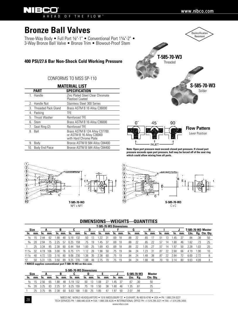
Bronze Ball ValvesThree-Way Body • Full Port ¹⁄₂"-1" • Conventional Port 1¹⁄₄"-2" •3-Way Bronze Ball Valve • Bronze Trim • Blowout-Proof Stem
400 PSI/27.6 Bar Non-Shock Cold Working Pressure
CONFORMS TO MSS SP-110
T-585-70-W3Threaded
S-585-70-W3Solder
MATERIAL LISTPART SPECIFICATION
1. Handle Zinc Plated Steel Clear ChromatePlastisol Coated
2. Handle Nut Stainless Steel 300 Series3. Threaded Pack Gland Brass ASTM B 16 Alloy C360004. Packing TFE5. Thrust Washer Reinforced TFE6. Stem Brass ASTM B 16 Alloy C360007. Seat Ring (2) Reinforced TFE8. Ball Brass ASTM B 124 Alloy C37700
or ASTM B 16 Alloy C36000with Hard Chrome Plate
9. Body Bronze ASTM B 584 Alloy C8440010. Body End Piece Bronze ASTM B 584 Alloy C84400
DIMENSIONS—WEIGHTS—QUANTITIEST-585-70-W3 Dimensions
Size A B C D E F G H I J T-585-70-W3 MasterIn. mm. In. mm. In. mm. In. mm. In. mm. In. mm. In. mm. In. mm. In. mm. In. mm. In. mm. Lbs. Kg. Ctn. Qty.¹⁄₂ 15 2.44 62 1.88 48 5.19 132 .50 13 1.22 31 .69 18 .88 22 .65 17 .51 13 1.45 37 .84 .38 50³⁄₄ 20 2.94 75 2.25 57 6.25 159 .75 19 1.45 37 .69 18 .88 22 .85 22 .57 14 1.80 46 1.62 .73 25
1 25 3.34 85 2.38 60 6.44 164 1.00 25 1.69 43 .69 18 .88 22 1.05 27 .57 14 1.97 50 2.28 1.03 20†1 ¹⁄₄ 32 4.19 106 3.00 76 6.75 171 1.12 28 1.98 50 .75 19 .94 24 1.23 31 .87 22 2.60 66 4.19 1.90 10†1 ¹⁄₂ 40 4.72 120 3.16 80 9.06 230 1.38 35 2.38 60 .75 19 .94 24 1.48 38 .87 22 2.84 72 6.00 2.72 8†2 50 5.31 135 3.50 89 9.25 235 1.88 48 2.75 70 .75 19 .94 24 1.88 48 .70 18 3.14 80 9.03 4.09 4† NIBCO supplies conventional port T-580-70-W3 on this size.
S-585-70-W3 DimensionsSize A B C D E J S-585-70-W3 Master
In. mm. In. mm. In. mm. In. mm. In. mm. In. mm. In. mm. Lbs. Kg. Ctn. Qty.¹⁄₂ 15 2.56 65 1.88 48 5.19 132 .50 13 1.08 27 1.45 37 .67 .30 50³⁄₄ 20 3.25 83 2.25 57 6.25 159 .75 19 1.50 38 1.80 46 1.35 .61 25
1 25 3.75 95 2.38 60 6.63 168 1.00 25 1.85 47 1.97 50 2.07 .94 20
Flow PatternLever Position
S-585-70-W3C x C
T-585-70-W3NPT x NPT
Note: Open port pressure must exceed closed port pressure. If closed portpressure exceeds open port pressure, ball may be forced off of the seat ringwhich could allow mixing from all ports.
NIBCO INC. WORLD HEADQUARTERS • 1516 MIDDLEBURY ST. • ELKHART, IN 46516-4740 • USA • PH: 1.800.234.0227 TECH SERVICES PH: 1.888.446.4226 • FAX: 1.888.336.4226 • INTERNATIONAL OFFICE PH: +1.574.295.3221 • FAX: +1.574.295.3455
www.nibco.com
A H E A D O F T H E F L O W ™
wwwwww..nniibbccoo..ccoomm
29
DezincificationResistant
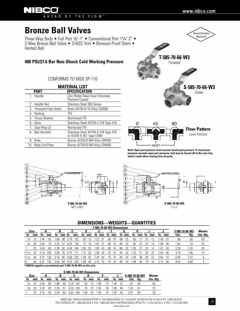
Bronze Ball ValvesThree-Way Body • Full Port ¹⁄₂"-1" • Conventional Port 1¹⁄₄"-2" •3-Way Bronze Ball Valve • 316SS Trim • Blowout-Proof Stem •Vented Ball
400 PSI/27.6 Bar Non-Shock Cold Working Pressure
CONFORMS TO MSS SP-110
T-585-70-66-W3Threaded
S-585-70-66-W3Solder
MATERIAL LISTPART SPECIFICATION
1. Handle Zinc Plated Steel Clear ChromatePlastisol Coated
2. Handle Nut Stainless Steel 300 Series3. Threaded Pack Gland Brass ASTM B 16 Alloy C360004. Packing TFE5. Thrust Washer Reinforced TFE6. Stem Stainless Steel ASTM A 276 Type 3167. Seat Ring (2) Reinforced TFE8. Ball (Vented) Stainless Steel ASTM A 276 Type 316
or ASTM A 351 Type CF8M9. Body Bronze ASTM B 584 Alloy C84400
10. Body End Piece Bronze ASTM B 584 Alloy C84400
DIMENSIONS—WEIGHTS—QUANTITIEST-585-70-66-W3 Dimensions
Size A B C D E F G H I J T-585-70-66-W3 MasterIn. mm. In. mm. In. mm. In. mm. In. mm. In. mm. In. mm. In. mm. In. mm. In. mm. In. mm. Lbs. Kg. Ctn. Qty.¹⁄₂ 15 2.44 62 1.88 48 5.19 132 .50 13 1.22 31 .69 18 .88 22 .65 17 .51 13 1.45 37 .84 .38 50³⁄₄ 20 2.94 75 2.25 57 6.25 159 .75 19 1.45 37 .69 18 .88 22 .85 22 .57 14 1.80 46 1.62 .73 25
1 25 3.34 85 2.38 60 6.44 164 1.00 25 1.69 43 .69 18 .88 22 1.05 27 .57 14 1.97 50 2.28 1.03 20†1 ¹⁄₄ 32 4.19 106 3.00 76 6.75 171 1.12 28 1.98 50 .75 19 .94 24 1.23 31 .87 22 2.60 66 4.19 1.90 10†1 ¹⁄₂ 40 4.72 120 3.16 80 9.06 230 1.38 35 2.38 60 .75 19 .94 24 1.48 38 .87 22 2.84 72 6.00 2.72 8†2 50 5.31 135 3.50 89 9.25 235 1.88 48 2.75 70 .75 19 .94 24 1.88 48 .70 18 3.14 80 9.03 4.09 4† NIBCO supplies conventional port T-580-70-66-W3 on this size.
S-585-70-66-W3 DimensionsSize A B C D E J S-585-70-66-W3 Master
In. mm. In. mm. In. mm. In. mm. In. mm. In. mm. In. mm. Lbs. Kg. Ctn. Qty.¹⁄₂ 15 2.56 65 1.88 48 5.19 132 .50 13 1.08 27 1.45 37 .67 .30 50³⁄₄ 20 3.25 83 2.25 57 6.25 159 .75 19 1.50 38 1.80 46 1.35 .61 25
1 25 3.75 95 2.38 60 6.63 168 1.00 25 1.85 47 1.97 50 2.07 .94 20
Flow PatternLever Position
S-585-70-66-W3C x C
T-585-70-66-W3NPT x NPT
Note: Open port pressure must exceed closed port pressure. If closed portpressure exceeds open port pressure, ball may be forced off of the seat ringwhich could allow mixing from all ports.
NIBCO INC. WORLD HEADQUARTERS • 1516 MIDDLEBURY ST. • ELKHART, IN 46516-4740 • USA • PH: 1.800.234.0227 TECH SERVICES PH: 1.888.446.4226 • FAX: 1.888.336.4226 • INTERNATIONAL OFFICE PH: +1.574.295.3221 • FAX: +1.574.295.3455
www.nibco.com
A H E A D O F T H E F L O W ™
wwwwww..nniibbccoo..ccoomm
30
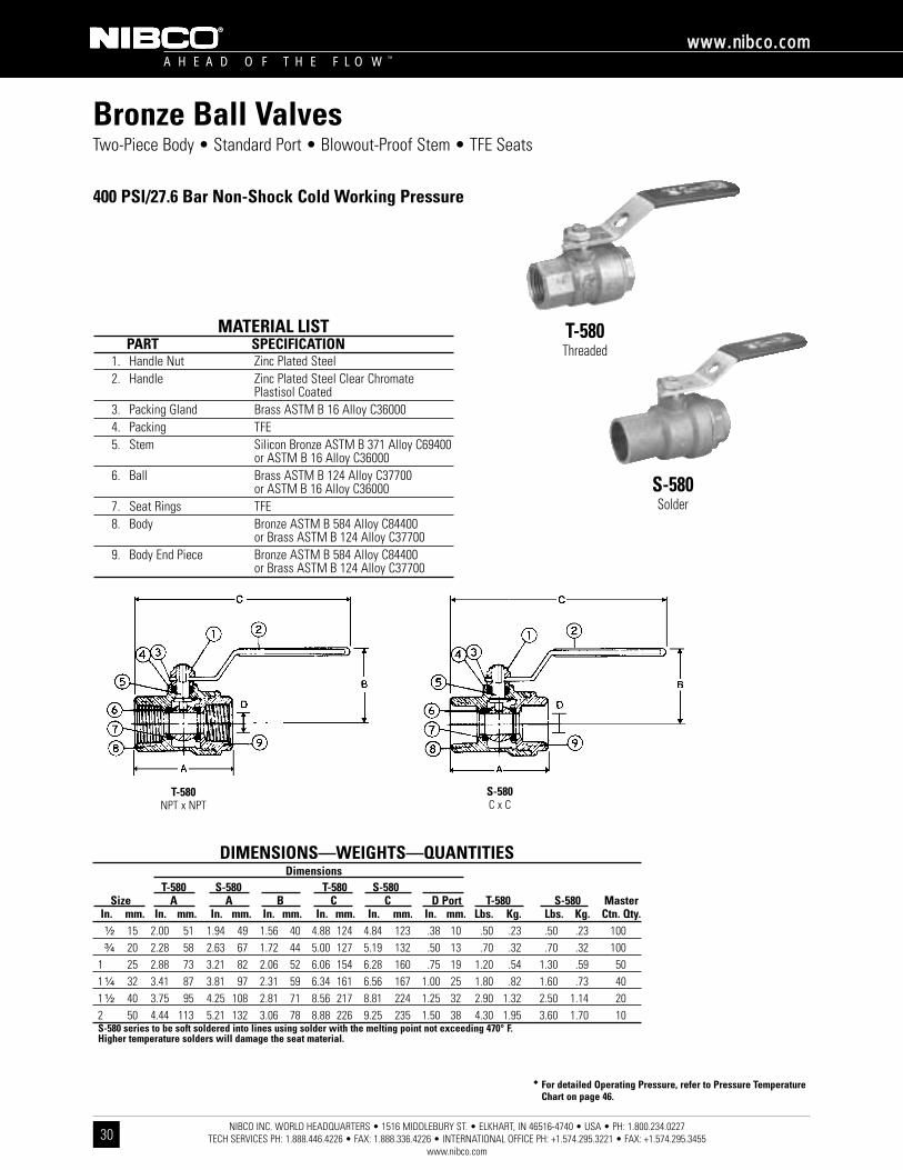
Two-Piece Body • Standard Port • Blowout-Proof Stem • TFE Seats
400 PSI/27.6 Bar Non-Shock Cold Working Pressure
T-580Threaded
S-580Solder
MATERIAL LISTPART SPECIFICATION
1. Handle Nut Zinc Plated Steel2. Handle Zinc Plated Steel Clear Chromate
Plastisol Coated3. Packing Gland Brass ASTM B 16 Alloy C360004. Packing TFE5. Stem Silicon Bronze ASTM B 371 Alloy C69400
or ASTM B 16 Alloy C360006. Ball Brass ASTM B 124 Alloy C37700
or ASTM B 16 Alloy C360007. Seat Rings TFE8. Body Bronze ASTM B 584 Alloy C84400
or Brass ASTM B 124 Alloy C377009. Body End Piece Bronze ASTM B 584 Alloy C84400
or Brass ASTM B 124 Alloy C37700
�� For detailed Operating Pressure, refer to Pressure TemperatureChart on page 46.
DIMENSIONS—WEIGHTS—QUANTITIESDimensions
T-580 S-580 T-580 S-580Size A A B C C D Port T-580 S-580 Master
In. mm. In. mm. In. mm. In. mm. In. mm. In. mm. In. mm. Lbs. Kg. Lbs. Kg. Ctn. Qty.¹⁄₂ 15 2.00 51 1.94 49 1.56 40 4.88 124 4.84 123 .38 10 .50 .23 .50 .23 100³⁄₄ 20 2.28 58 2.63 67 1.72 44 5.00 127 5.19 132 .50 13 .70 .32 .70 .32 100
1 25 2.88 73 3.21 82 2.06 52 6.06 154 6.28 160 .75 19 1.20 .54 1.30 .59 501 ¹⁄₄ 32 3.41 87 3.81 97 2.31 59 6.34 161 6.56 167 1.00 25 1.80 .82 1.60 .73 401 ¹⁄₂ 40 3.75 95 4.25 108 2.81 71 8.56 217 8.81 224 1.25 32 2.90 1.32 2.50 1.14 202 50 4.44 113 5.21 132 3.06 78 8.88 226 9.25 235 1.50 38 4.30 1.95 3.60 1.70 10S-580 series to be soft soldered into lines using solder with the melting point not exceeding 470° F. Higher temperature solders will damage the seat material.
T-580NPT x NPT
S-580C x C
Bronze Ball Valves
NIBCO INC. WORLD HEADQUARTERS • 1516 MIDDLEBURY ST. • ELKHART, IN 46516-4740 • USA • PH: 1.800.234.0227 TECH SERVICES PH: 1.888.446.4226 • FAX: 1.888.336.4226 • INTERNATIONAL OFFICE PH: +1.574.295.3221 • FAX: +1.574.295.3455
www.nibco.com
A H E A D O F T H E F L O W ™
wwwwww..nniibbccoo..ccoomm
31
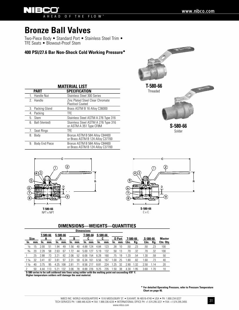
Two-Piece Body • Standard Port • Stainless Steel Trim • TFE Seats • Blowout-Proof Stem
400 PSI/27.6 Bar Non-Shock Cold Working Pressure��
T-580-66Threaded
S-580-66Solder
MATERIAL LISTPART SPECIFICATION
1. Handle Nut Stainless Steel 300 Series2. Handle Zinc Plated Steel Clear Chromate
Plastisol Coated3. Packing Gland Brass ASTM B 16 Alloy C360004. Packing TFE5. Stem Stainless Steel ASTM A 276 Type 3166. Ball (Vented) Stainless Steel ASTM A 276 Type 316
or ASTM A 351 Type CF8M7. Seat Rings TFE8. Body Bronze ASTM B 584 Alloy C84400
or Brass ASTM B 124 Alloy C377009. Body End Piece Bronze ASTM B 584 Alloy C84400
or Brass ASTM B 124 Alloy C37700
�� For detailed Operating Pressure, refer to Pressure TemperatureChart on page 46.
T-580-66NPT x NPT
S-580-66C x C
DIMENSIONS—WEIGHTS—QUANTITIESDimensions
T-580-66 S-580-66 T-580-66 S-580-66Size A A B C C D Port T-580-66 S-580-66 Master
In. mm. In. mm. In. mm. In. mm. In. mm. In. mm. In. mm. Lbs. Kg. Lbs. Kg. Ctn. Qty.¹⁄₂ 15 2.00 51 1.94 49 1.56 40 4.88 124 4.84 123 .38 10 .50 .23 .50 .23 100³⁄₄ 20 2.28 58 2.63 67 1.72 44 5.00 127 5.19 132 .50 13 .70 .32 .70 .32 100
1 25 2.88 73 3.21 82 2.06 52 6.06 154 6.28 160 .75 19 1.20 .54 1.30 .59 501 ¹⁄₄ 32 3.41 87 3.81 97 2.31 59 6.34 161 6.56 167 1.00 25 1.80 .82 1.60 .73 401 ¹⁄₂ 40 3.75 95 4.25 108 2.81 71 8.56 217 8.81 224 1.25 32 2.90 1.32 2.50 1.14 202 50 4.44 113 5.21 132 3.06 78 8.88 226 9.25 235 1.50 38 4.30 1.95 3.60 1.70 10S-580 series to be soft soldered into lines using solder with the melting point not exceeding 470° F. Higher temperature solders will damage the seat material.
Bronze Ball Valves
NIBCO INC. WORLD HEADQUARTERS • 1516 MIDDLEBURY ST. • ELKHART, IN 46516-4740 • USA • PH: 1.800.234.0227 TECH SERVICES PH: 1.888.446.4226 • FAX: 1.888.336.4226 • INTERNATIONAL OFFICE PH: +1.574.295.3221 • FAX: +1.574.295.3455
www.nibco.com
A H E A D O F T H E F L O W ™
wwwwww..nniibbccoo..ccoomm
32
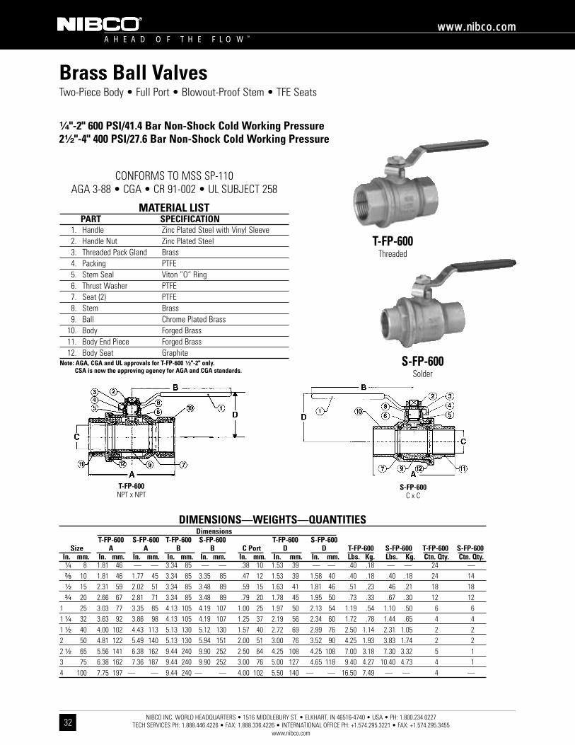
Brass Ball ValvesTwo-Piece Body • Full Port • Blowout-Proof Stem • TFE Seats
¹⁄₄"-2" 600 PSI/41.4 Bar Non-Shock Cold Working Pressure2¹⁄₂"-4" 400 PSI/27.6 Bar Non-Shock Cold Working Pressure
CONFORMS TO MSS SP-110AGA 3-88 • CGA • CR 91-002 • UL SUBJECT 258
T-FP-600Threaded
S-FP-600Solder
MATERIAL LISTPART SPECIFICATION
1. Handle Zinc Plated Steel with Vinyl Sleeve2. Handle Nut Zinc Plated Steel3. Threaded Pack Gland Brass4. Packing PTFE5. Stem Seal Viton ”O“ Ring6. Thrust Washer PTFE7. Seat (2) PTFE8. Stem Brass9. Ball Chrome Plated Brass
10. Body Forged Brass11. Body End Piece Forged Brass12. Body Seat Graphite
Note: AGA, CGA and UL approvals for T-FP-600 ¹⁄₂"-2" only. CSA is now the approving agency for AGA and CGA standards.
DIMENSIONS—WEIGHTS—QUANTITIESDimensions
T-FP-600 S-FP-600 T-FP-600 S-FP-600 T-FP-600 S-FP-600Size A A B B C Port D D T-FP-600 S-FP-600 T-FP-600 S-FP-600
In. mm. In. mm. In. mm. In. mm. In. mm. In. mm. In. mm. In. mm. Lbs. Kg. Lbs. Kg. Ctn. Qty. Ctn. Qty.¹⁄₄ 8 1.81 46 — — 3.34 85 — — .38 10 1.53 39 — — .40 .18 — — 24 —³⁄₈ 10 1.81 46 1.77 45 3.34 85 3.35 85 .47 12 1.53 39 1.58 40 .40 .18 .40 .18 24 14¹⁄₂ 15 2.31 59 2.02 51 3.34 85 3.48 89 .59 15 1.63 41 1.81 46 .51 .23 .46 .21 18 18³⁄₄ 20 2.66 67 2.81 71 3.34 85 3.48 89 .79 20 1.78 45 1.95 50 .73 .33 .67 .30 12 12
1 25 3.03 77 3.35 85 4.13 105 4.19 107 1.00 25 1.97 50 2.13 54 1.19 .54 1.10 .50 6 61 ¹⁄₄ 32 3.63 92 3.86 98 4.13 105 4.19 107 1.25 37 2.19 56 2.34 60 1.72 .78 1.44 .65 4 41 ¹⁄₂ 40 4.00 102 4.43 113 5.13 130 5.12 130 1.57 40 2.72 69 2.99 76 2.50 1.14 2.31 1.05 2 22 50 4.81 122 5.49 140 5.13 130 5.94 151 2.00 51 3.00 76 3.52 90 4.25 1.93 3.83 1.74 2 22 ¹⁄₂ 65 5.56 141 6.38 162 9.44 240 9.90 252 2.50 64 4.25 108 4.25 108 7.00 3.18 7.30 3.32 5 13 75 6.38 162 7.36 187 9.44 240 9.90 252 3.00 76 5.00 127 4.65 118 9.40 4.27 10.40 4.73 4 14 100 7.75 197 — — 9.44 240 — — 4.00 102 5.50 140 — — 16.50 7.49 — — 4 —
T-FP-600NPT x NPT
S-FP-600C x C
NIBCO INC. WORLD HEADQUARTERS • 1516 MIDDLEBURY ST. • ELKHART, IN 46516-4740 • USA • PH: 1.800.234.0227 TECH SERVICES PH: 1.888.446.4226 • FAX: 1.888.336.4226 • INTERNATIONAL OFFICE PH: +1.574.295.3221 • FAX: +1.574.295.3455
www.nibco.com
A H E A D O F T H E F L O W ™
wwwwww..nniibbccoo..ccoomm
33
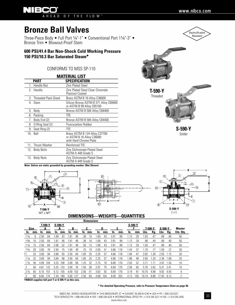
Three-Piece Body • Full Port ¹⁄₄"-1" • Conventional Port 1¹⁄₄"-3" •Bronze Trim • Blowout-Proof Stem
600 PSI/41.4 Bar Non-Shock Cold Working Pressure150 PSI/10.3 Bar Saturated Steam��
CONFORMS TO MSS SP-110
T-590-YThreaded
S-590-YSolder
MATERIAL LISTPART SPECIFICATION
1. Handle Nut Zinc Plated Steel2. Handle Zinc Plated Steel Clear Chromate
Plastisol Coated3. Threaded Pack Gland Brass ASTM B 16 Alloy C360004. Stem Silicon Bronze ASTM B 371 Alloy C69400
or ASTM B 99 Alloy C651005. Body Bronze ASTM B 584 Alloy C844006. Packing TFE7. Body End (2) Bronze ASTM B 584 Alloy C844008. O-Ring Seal (2) Fluorocarbon Rubber9. Seat Ring (2) TFE
10. Ball Brass ASTM B 124 Alloy C37700or ASTM B 16 Alloy C36000with Hard Chrome Plate
11. Thrust Washer Reinforced TFE12. Body Bolts Zinc Dichromate Plated Steel
ASTM A 449 Grade 513. Body Nuts Zinc Dichromate Plated Steel
ASTM A 449 Grade 5Note: Valves are static grounded by grounding washer. (Not Shown)
�� For detailed Operating Pressure, refer to Pressure Temperature Chart on page 46.
DIMENSIONS—WEIGHTS—QUANTITIESDimensions
T-590-Y S-590-Y S-590-YSize A A B C D E F T-590-Y S-590-Y Master
In. mm. In. mm. In. mm. In. mm. In. mm. In. mm. In. mm. In. mm. Lbs. Kg. Lbs. Kg. Ctn. Qty.† ¹⁄₄ 8 2.50 64 1.69 43 1.81 46 .38 10 1.69 43 3.91 99 1.13 29 1.03 .47 .89 .40 50† ³⁄₈ 10 2.50 64 1.81 46 1.81 46 .38 10 1.69 43 3.91 99 1.13 29 .98 .44 .89 .40 50† ¹⁄₂ 15 2.50 64 2.06 52 1.81 46 .50 13 1.69 43 3.91 99 1.13 29 1.03 .47 .89 .40 50† ³⁄₄ 20 3.00 76 2.94 75 1.94 49 .75 19 2.00 51 4.66 118 1.44 37 1.70 .77 1.59 .72 30
†1 25 3.69 94 3.66 93 2.50 64 1.00 25 2.25 57 4.66 118 1.84 47 2.82 1.28 2.55 1.15 201 ¹⁄₄ 32 3.69 94 3.84 98 2.50 64 1.00 25 2.25 57 4.66 118 1.88 48 2.65 1.20 2.38 1.08 201 ¹⁄₂ 40 4.09 104 4.25 108 2.69 68 1.25 32 2.75 70 6.69 170 2.03 52 3.77 1.71 3.42 1.55 102 50 4.81 122 5.25 133 3.00 76 1.50 38 2.97 75 6.69 170 2.56 65 5.78 2.62 5.31 2.41 102 ¹⁄₂ 65 6.16 157 6.12 155 4.00 102 2.00 51 3.63 92 6.69 170 3.19 81 10.75 4.88 9.92 4.50 43 80 6.84 174 7.44 189 5.00 127 2.50 64 4.09 104 8.00 203 4.13 105 19.14 8.68 17.93 8.13 2
†NIBCO supplies full port T or S-595-Y on this size.
T-590-YNPT x NPT
S-590-YC x C
Bronze Ball Valves DezincificationResistant

NIBCO INC. WORLD HEADQUARTERS • 1516 MIDDLEBURY ST. • ELKHART, IN 46516-4740 • USA • PH: 1.800.234.0227 TECH SERVICES PH: 1.888.446.4226 • FAX: 1.888.336.4226 • INTERNATIONAL OFFICE PH: +1.574.295.3221 • FAX: +1.574.295.3455
www.nibco.com
A H E A D O F T H E F L O W ™
wwwwww..nniibbccoo..ccoomm
34
Three-Piece Body • Full Port ¹⁄₄"-1" • Conventional Port 1¹⁄₄"-3" • 316SS Trim • Blowout-Proof Stem • Vented Ball
600 PSI/41.4 Bar Non-Shock Cold Working Pressure150 PSI/10.3 Bar Saturated Steam��
CONFORMS TO MSS SP-110
T-590-Y-66Threaded
S-590-Y-66Solder
MATERIAL LISTPART SPECIFICATION
1. Handle Nut Stainless Steel 300 Series2. Handle Zinc Plated Steel Clear Chromate
Plastisol Coated3. Threaded Pack Gland Brass ASTM B 16 Alloy C360004. Stem Stainless Steel ASTM A 276 Type 3165. Body Bronze ASTM B 584 Alloy C844006. Packing TFE7. Body End (2) Bronze ASTM B 584 Alloy C844008. O-Ring Seal (2) Fluorocarbon Rubber9. Seat Ring (2) TFE
10. Ball (Vented) Stainless Steel ASTM A 276 Type 316or ASTM A 351 Type CF8M
11. Thrust Washer Reinforced TFE12. Body Bolts Zinc Dichromate Plated Steel
ASTM A 449 Grade 513. Body Nuts Zinc Dichromate Plated Steel
ASTM A 449 Grade 5Note: Valves are static grounded by a grounding washer. (Not Shown)
�� For detailed Operating Pressure, refer to Pressure Temperature Chart on page 46.
DIMENSIONS—WEIGHTS—QUANTITIESDimensions
T-590-Y-66 S-590-Y-66 S-590-Y-66Size A A B C D E F T-590-Y-66 S-590-Y-66 Master
In. mm. In. mm. In. mm. In. mm. In. mm. In. mm. In. mm. In. mm. Lbs. Kg. Lbs. Kg. Ctn. Qty.† ¹⁄₄ 8 2.50 64 1.69 43 1.81 46 .38 10 1.69 43 3.91 99 1.13 29 1.03 .47 .89 .40 50† ³⁄₈ 10 2.50 64 1.81 46 1.81 46 .38 10 1.69 43 3.91 99 1.13 29 .98 .44 .89 .40 50† ¹⁄₂ 15 2.50 64 2.06 52 1.81 46 .50 13 1.69 43 3.91 99 1.13 29 1.03 .47 .89 .40 50†³⁄₄ 20 3.00 76 2.94 75 1.94 49 .75 19 2.00 51 4.66 118 1.44 37 1.70 .77 1.59 .72 30
†1 25 3.69 94 3.66 93 2.50 64 1.00 25 2.25 57 4.66 118 1.84 47 2.82 1.28 2.55 1.15 201 ¹⁄₄ 32 3.69 94 3.84 98 2.50 64 1.00 25 2.25 57 4.66 118 1.88 48 2.65 1.20 2.38 1.08 201 ¹⁄₂ 40 4.09 104 4.25 108 2.69 68 1.25 32 2.75 70 6.69 170 2.03 52 3.77 1.71 3.42 1.55 102 50 4.81 122 5.25 133 3.00 76 1.50 38 2.97 75 6.69 170 2.56 65 5.78 2.62 5.31 2.41 102 ¹⁄₂ 65 6.16 157 6.12 155 4.00 102 2.00 51 3.63 92 6.69 170 3.19 81 10.75 4.88 9.92 4.50 43 80 6.84 174 7.44 189 5.00 127 2.50 64 4.09 104 8.00 203 4.13 105 19.14 8.68 17.93 8.13 2
†NIBCO supplies full port T or S-595-Y-66 on this size.
T-590-Y-66NPT x NPT
S-590-Y-66C x C
Bronze Ball Valves DezincificationResistant

NIBCO INC. WORLD HEADQUARTERS • 1516 MIDDLEBURY ST. • ELKHART, IN 46516-4740 • USA • PH: 1.800.234.0227 TECH SERVICES PH: 1.888.446.4226 • FAX: 1.888.336.4226 • INTERNATIONAL OFFICE PH: +1.574.295.3221 • FAX: +1.574.295.3455
www.nibco.com
A H E A D O F T H E F L O W ™
wwwwww..nniibbccoo..ccoomm
35
Three-Piece Body • Full Port ¹⁄₄"-1" • Conventional Port 1¹⁄₄"-3" • UL Listed for Flammable Liquids and LP Gas • Blowout-Proof Stem
250 PSI/17.2 Bar Non-Shock LP Gas per UL842
CONFORMS TO MSS SP-110 • UL842
T-590-Y-ULThreaded
MATERIAL LISTPART SPECIFICATION
1. Handle Nut Zinc Plated Steel2. Handle Zinc Plated Steel Clear Chromate
Plastisol Coated3. Threaded Pack Gland Brass ASTM B 16 Alloy C360004. Stem Silicon Bronze ASTM B 371 Alloy C69400
or ASTM B 99 Alloy C651005. Body Bronze ASTM B 584 Alloy C844006. Packing TFE7. Body End (2) Bronze ASTM B 584 Alloy C844008. O-Ring Seal (2) Fluorocarbon Rubber9. Seat Ring (2) TFE
10. Ball Brass ASTM B 124 Alloy C37700or ASTM B 16 Alloy C36000with Hard Chrome Plate
11. Thrust Washer Reinforced TFE12. Body Bolts Zinc Dichromate Plated Steel
ASTM A 449 Grade 513. Body Nuts Zinc Dichromate Plated Steel
ASTM A 449 Grade 5Note: Valves are static grounded by a grounding washer. (Not Shown)
DIMENSIONS—WEIGHTS—QUANTITIESDimensions
Size A B C D E T-590-Y-UL MasterIn. mm. In. mm. In. mm. In. mm. In. mm. In. mm. Lbs. Kg. Ctn. Qty.
† ¹⁄₄ 8 2.50 64 1.81 46 .38 10 1.06 27 3.90 99 .94 .43 50† ³⁄₈ 10 2.50 64 1.81 46 .38 10 1.06 27 3.90 99 .94 .43 50† ¹⁄₂ 15 2.50 64 1.81 46 .50 13 1.06 27 3.90 99 1.01 .47 50† ³⁄₄ 20 3.00 76 1.94 49 .75 19 2.00 51 4.66 118 1.73 .79 30†1 25 3.69 94 2.50 64 1.00 25 2.25 57 4.66 118 2.75 1.25 201 ¹⁄₄ 32 3.69 94 2.50 64 1.00 25 2.25 57 4.66 118 2.65 1.20 201 ¹⁄₂ 40 4.09 104 2.69 68 1.25 32 2.75 70 6.69 170 3.77 1.71 102 50 4.56 116 3.00 76 1.50 38 2.97 75 6.69 170 5.78 2.62 102 ¹⁄₂ 65 6.16 156 4.00 102 2.00 51 3.63 92 6.69 170 10.75 4.88 43 80 6.90 175 5.00 127 2.50 64 4.09 104 8.00 203 19.14 8.68 2
†NIBCO supplies full port T-595-Y-UL on this size.
UL Listed For:YSDT LP gas shut-offYQNZ Compressed gas shut-offYRPV Gas shut-offYRBX Flammable liquid shut-offMHKZ Manual valves
CUL Listed For:YSDT7 LP gas shut-off for Canada
ServiceA - Air or non-toxic, non-flammable gasG - City gas supplied by public utilities
GA - GasolineLP - Liquified petroleum gas, 250 PSI max.02 - No. 1 and 2 fuel oil04 - No. 4 fuel oil05 - No. 5 fuel oil06 - No. 6 fuel oil
T-590-Y-ULT-595-Y-ULNPT x NPT
Bronze Ball Valves DezincificationResistant
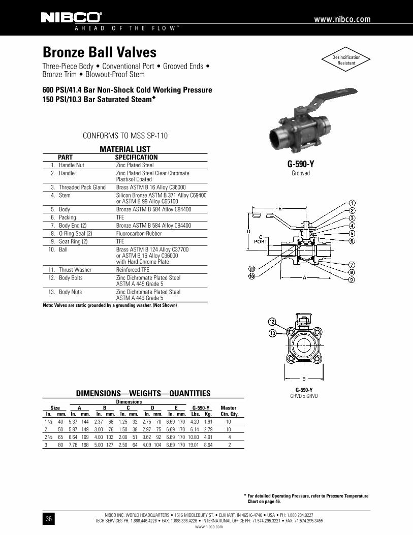
NIBCO INC. WORLD HEADQUARTERS • 1516 MIDDLEBURY ST. • ELKHART, IN 46516-4740 • USA • PH: 1.800.234.0227 TECH SERVICES PH: 1.888.446.4226 • FAX: 1.888.336.4226 • INTERNATIONAL OFFICE PH: +1.574.295.3221 • FAX: +1.574.295.3455
www.nibco.com
A H E A D O F T H E F L O W ™
wwwwww..nniibbccoo..ccoomm
36
Three-Piece Body • Conventional Port • Grooved Ends • Bronze Trim • Blowout-Proof Stem
600 PSI/41.4 Bar Non-Shock Cold Working Pressure150 PSI/10.3 Bar Saturated Steam��
G-590-YGrooved
MATERIAL LISTPART SPECIFICATION
1. Handle Nut Zinc Plated Steel2. Handle Zinc Plated Steel Clear Chromate
Plastisol Coated3. Threaded Pack Gland Brass ASTM B 16 Alloy C360004. Stem Silicon Bronze ASTM B 371 Alloy C69400
or ASTM B 99 Alloy C651005. Body Bronze ASTM B 584 Alloy C844006. Packing TFE7. Body End (2) Bronze ASTM B 584 Alloy C844008. O-Ring Seal (2) Fluorocarbon Rubber9. Seat Ring (2) TFE
10. Ball Brass ASTM B 124 Alloy C37700or ASTM B 16 Alloy C36000with Hard Chrome Plate
11. Thrust Washer Reinforced TFE12. Body Bolts Zinc Dichromate Plated Steel
ASTM A 449 Grade 513. Body Nuts Zinc Dichromate Plated Steel
ASTM A 449 Grade 5Note: Valves are static grounded by a grounding washer. (Not Shown)
�� For detailed Operating Pressure, refer to Pressure TemperatureChart on page 46.
DIMENSIONS—WEIGHTS—QUANTITIESDimensions
Size A B C D E G-590-Y MasterIn. mm. In. mm. In. mm. In. mm. In. mm. In. mm. Lbs. Kg. Ctn. Qty.
1 ¹⁄₂ 40 5.37 144 2.37 68 1.25 32 2.75 70 6.69 170 4.20 1.91 102 50 5.87 149 3.00 76 1.50 38 2.97 75 6.69 170 6.14 2.79 102 ¹⁄₂ 65 6.64 169 4.00 102 2.00 51 3.62 92 6.69 170 10.80 4.91 43 80 7.78 198 5.00 127 2.50 64 4.09 104 6.69 170 19.01 8.64 2
G-590-YGRVD x GRVD
CONFORMS TO MSS SP-110
Bronze Ball Valves DezincificationResistant

NIBCO INC. WORLD HEADQUARTERS • 1516 MIDDLEBURY ST. • ELKHART, IN 46516-4740 • USA • PH: 1.800.234.0227 TECH SERVICES PH: 1.888.446.4226 • FAX: 1.888.336.4226 • INTERNATIONAL OFFICE PH: +1.574.295.3221 • FAX: +1.574.295.3455
www.nibco.com
A H E A D O F T H E F L O W ™
wwwwww..nniibbccoo..ccoomm
37
Three-Piece Body • Conventional Port • Grooved Ends • 316SS Trim • Blowout-Proof Stem • Vented Ball
600 PSI/41.4 Bar Non-Shock Cold Working Pressure150 PSI/10.3 Bar Saturated Steam��
G-590-Y-66Grooved
MATERIAL LISTPART SPECIFICATION
1. Handle Nut Stainless Steel 300 Series2. Handle Zinc Plated Steel Clear Chromate
Plastisol Coated3. Threaded Pack Gland Brass ASTM B 16 Alloy C360004. Stem Stainless Steel ASTM A 276 Type 3165. Body Bronze ASTM B 584 Alloy C844006. Packing TFE7. Body End (2) Bronze ASTM B 584 Alloy C844008. O-Ring Seal (2) Fluorocarbon Rubber9. Seat Ring (2) TFE
10. Ball (Vented) Stainless Steel ASTM A 276 Type 316or ASTM A 351 Type CF8M
11. Thrust Washer Reinforced TFE12. Body Bolts Zinc Dichromate Plated Steel
ASTM A 449 Grade 513. Body Nuts Zinc Dichromate Plated Steel
ASTM A 449 Grade 5Note: Valves are static grounded by a grounding washer. (Not Shown)
�� For detailed Operating Pressure, refer to Pressure TemperatureChart on page 46.
DIMENSIONS—WEIGHTS—QUANTITIESDimensions
Size A B C D E G-590-Y-66 MasterIn. mm. In. mm. In. mm. In. mm. In. mm. In. mm. Lbs. Kg. Ctn. Qty.
1 ¹⁄₂ 40 5.37 144 2.37 68 1.25 32 2.75 70 6.69 170 4.20 1.91 102 50 5.87 149 3.00 76 1.50 38 2.97 75 6.69 170 6.14 2.79 102 ¹⁄₂ 65 6.64 169 4.00 102 2.00 51 3.62 92 6.69 170 10.80 4.91 43 80 7.78 198 5.00 127 2.50 64 4.09 104 6.69 170 19.01 8.64 2
G-590-Y-66GRVD x GRVD
CONFORMS TO MSS SP-110
Bronze Ball Valves DezincificationResistant
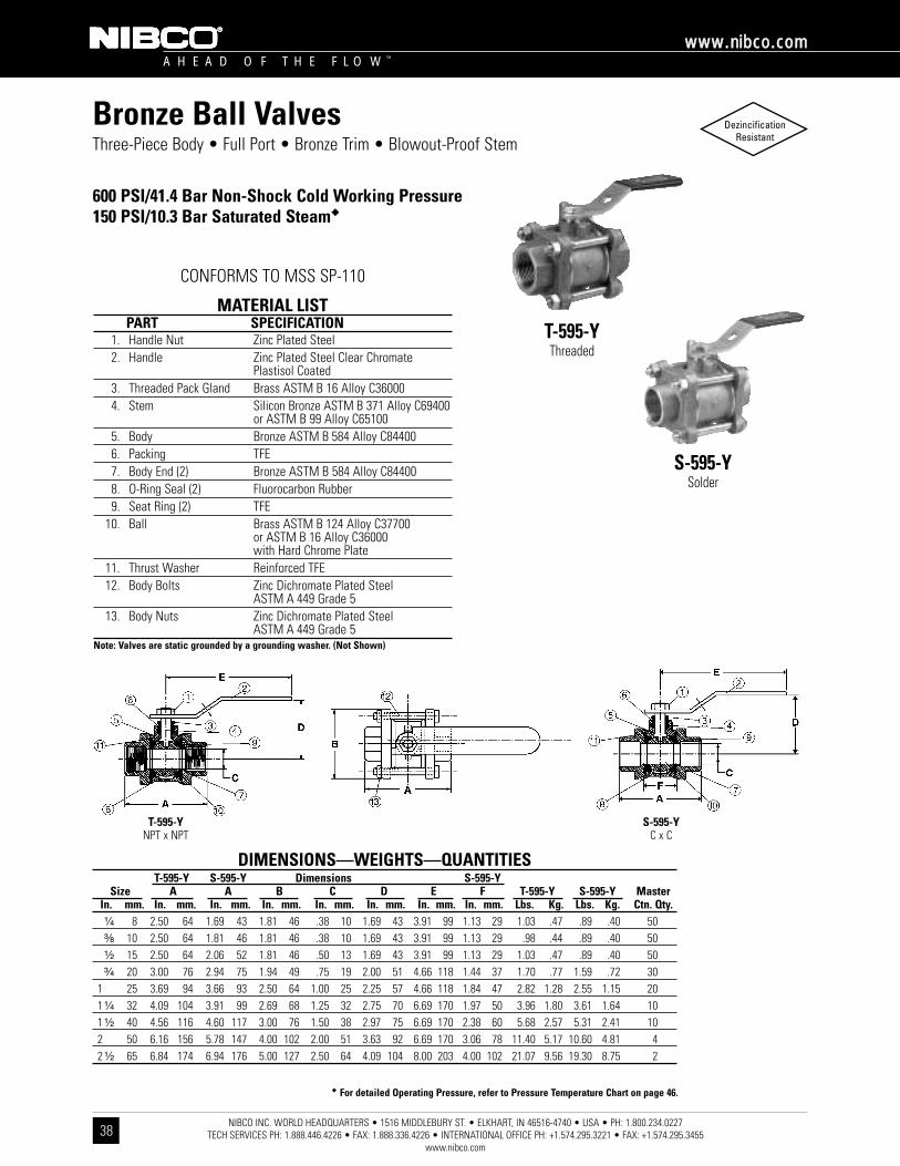
NIBCO INC. WORLD HEADQUARTERS • 1516 MIDDLEBURY ST. • ELKHART, IN 46516-4740 • USA • PH: 1.800.234.0227 TECH SERVICES PH: 1.888.446.4226 • FAX: 1.888.336.4226 • INTERNATIONAL OFFICE PH: +1.574.295.3221 • FAX: +1.574.295.3455
www.nibco.com
A H E A D O F T H E F L O W ™
wwwwww..nniibbccoo..ccoomm
38
Three-Piece Body • Full Port • Bronze Trim • Blowout-Proof Stem
600 PSI/41.4 Bar Non-Shock Cold Working Pressure150 PSI/10.3 Bar Saturated Steam��
CONFORMS TO MSS SP-110
T-595-YThreaded
S-595-YSolder
MATERIAL LISTPART SPECIFICATION
1. Handle Nut Zinc Plated Steel2. Handle Zinc Plated Steel Clear Chromate
Plastisol Coated3. Threaded Pack Gland Brass ASTM B 16 Alloy C360004. Stem Silicon Bronze ASTM B 371 Alloy C69400
or ASTM B 99 Alloy C651005. Body Bronze ASTM B 584 Alloy C844006. Packing TFE7. Body End (2) Bronze ASTM B 584 Alloy C844008. O-Ring Seal (2) Fluorocarbon Rubber9. Seat Ring (2) TFE
10. Ball Brass ASTM B 124 Alloy C37700or ASTM B 16 Alloy C36000with Hard Chrome Plate
11. Thrust Washer Reinforced TFE12. Body Bolts Zinc Dichromate Plated Steel
ASTM A 449 Grade 513. Body Nuts Zinc Dichromate Plated Steel
ASTM A 449 Grade 5Note: Valves are static grounded by a grounding washer. (Not Shown)
�� For detailed Operating Pressure, refer to Pressure Temperature Chart on page 46.
DIMENSIONS—WEIGHTS—QUANTITIEST-595-Y S-595-Y Dimensions S-595-Y
Size A A B C D E F T-595-Y S-595-Y MasterIn. mm. In. mm. In. mm. In. mm. In. mm. In. mm. In. mm. In. mm. Lbs. Kg. Lbs. Kg. Ctn. Qty.¹⁄₄ 8 2.50 64 1.69 43 1.81 46 .38 10 1.69 43 3.91 99 1.13 29 1.03 .47 .89 .40 50³⁄₈ 10 2.50 64 1.81 46 1.81 46 .38 10 1.69 43 3.91 99 1.13 29 .98 .44 .89 .40 50¹⁄₂ 15 2.50 64 2.06 52 1.81 46 .50 13 1.69 43 3.91 99 1.13 29 1.03 .47 .89 .40 50³⁄₄ 20 3.00 76 2.94 75 1.94 49 .75 19 2.00 51 4.66 118 1.44 37 1.70 .77 1.59 .72 30
1 25 3.69 94 3.66 93 2.50 64 1.00 25 2.25 57 4.66 118 1.84 47 2.82 1.28 2.55 1.15 201 ¹⁄₄ 32 4.09 104 3.91 99 2.69 68 1.25 32 2.75 70 6.69 170 1.97 50 3.96 1.80 3.61 1.64 101 ¹⁄₂ 40 4.56 116 4.60 117 3.00 76 1.50 38 2.97 75 6.69 170 2.38 60 5.68 2.57 5.31 2.41 102 50 6.16 156 5.78 147 4.00 102 2.00 51 3.63 92 6.69 170 3.06 78 11.40 5.17 10.60 4.81 42 ¹⁄₂ 65 6.84 174 6.94 176 5.00 127 2.50 64 4.09 104 8.00 203 4.00 102 21.07 9.56 19.30 8.75 2
T-595-YNPT x NPT
S-595-YC x C
Bronze Ball Valves DezincificationResistant
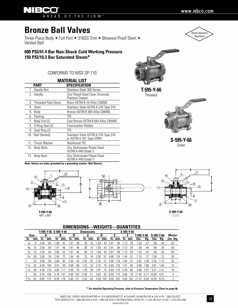
NIBCO INC. WORLD HEADQUARTERS • 1516 MIDDLEBURY ST. • ELKHART, IN 46516-4740 • USA • PH: 1.800.234.0227 TECH SERVICES PH: 1.888.446.4226 • FAX: 1.888.336.4226 • INTERNATIONAL OFFICE PH: +1.574.295.3221 • FAX: +1.574.295.3455
www.nibco.com
A H E A D O F T H E F L O W ™
wwwwww..nniibbccoo..ccoomm
39
Three-Piece Body • Full Port • 316SS Trim • Blowout-Proof Stem •Vented Ball
600 PSI/41.4 Bar Non-Shock Cold Working Pressure150 PSI/10.3 Bar Saturated Steam��
CONFORMS TO MSS SP-110
T-595-Y-66Threaded
S-595-Y-66Solder
MATERIAL LISTPART SPECIFICATION
1. Handle Nut Stainless Steel 300 Series2. Handle Zinc Plated Steel Clear Chromate
Plastisol Coated3. Threaded Pack Gland Brass ASTM B 16 Alloy C360004. Stem Stainless Steel ASTM A 276 Type 3165. Body Bronze ASTM B 584 Alloy C844006. Packing TFE7. Body End (2) Cast Bronze ASTM B 584 Alloy C844008. O-Ring Seal (2) Fluorocarbon Rubber9. Seat Ring (2) TFE
10. Ball (Vented) Stainless Steel ASTM A 276 Type 316or ASTM A 351 Type CF8M
11. Thrust Washer Reinforced TFE12. Body Bolts Zinc Dichromate Plated Steel
ASTM A 449 Grade 513. Body Nuts Zinc Dichromate Plated Steel
ASTM A 449 Grade 5Note: Valves are static grounded by a grounding washer. (Not Shown)
�� For detailed Operating Pressure, refer to Pressure Temperature Chart on page 46.
T-595-Y-66NPT x NPT
S-595-Y-66C x C
DIMENSIONS—WEIGHTS—QUANTITIEST-595-Y-66 S-595-Y-66 Dimensions S-595-Y-66
Size A A B C D E F T-595-Y-66 S-595-Y-66 MasterIn. mm. In. mm. In. mm. In. mm. In. mm. In. mm. In. mm. In. mm. Lbs. Kg. Lbs. Kg. Ctn. Qty.¹⁄₄ 8 2.50 64 1.69 43 1.81 46 .38 10 1.69 43 3.91 99 1.13 29 1.03 .47 .89 .40 50³⁄₈ 10 2.50 64 1.81 46 1.81 46 .38 10 1.69 43 3.91 99 1.13 29 .98 .44 .89 .40 50¹⁄₂ 15 2.50 64 2.06 52 1.81 46 .50 13 1.69 43 3.91 99 1.13 29 1.03 .47 .89 .40 50³⁄₄ 20 3.00 76 2.94 75 1.94 49 .75 19 2.00 51 4.66 118 1.44 37 1.70 .77 1.59 .72 30
1 25 3.69 94 3.66 93 2.50 64 1.00 25 2.25 57 4.66 118 1.84 47 2.82 1.28 2.55 1.15 201 ¹⁄₄ 32 4.09 104 3.91 99 2.69 68 1.25 32 2.75 70 6.69 170 1.97 50 3.96 1.80 3.61 1.64 101 ¹⁄₂ 40 4.56 116 4.60 117 3.00 76 1.50 38 2.97 75 6.69 170 2.38 60 5.68 2.57 5.31 2.41 102 50 6.16 156 5.78 147 4.00 102 2.00 51 3.63 92 6.69 170 3.06 78 11.40 5.17 10.60 4.81 42 ¹⁄₂ 65 6.84 174 6.94 176 5.00 127 2.50 64 4.09 104 8.00 203 4.00 102 21.07 9.56 19.30 8.75 2
Bronze Ball Valves DezincificationResistant
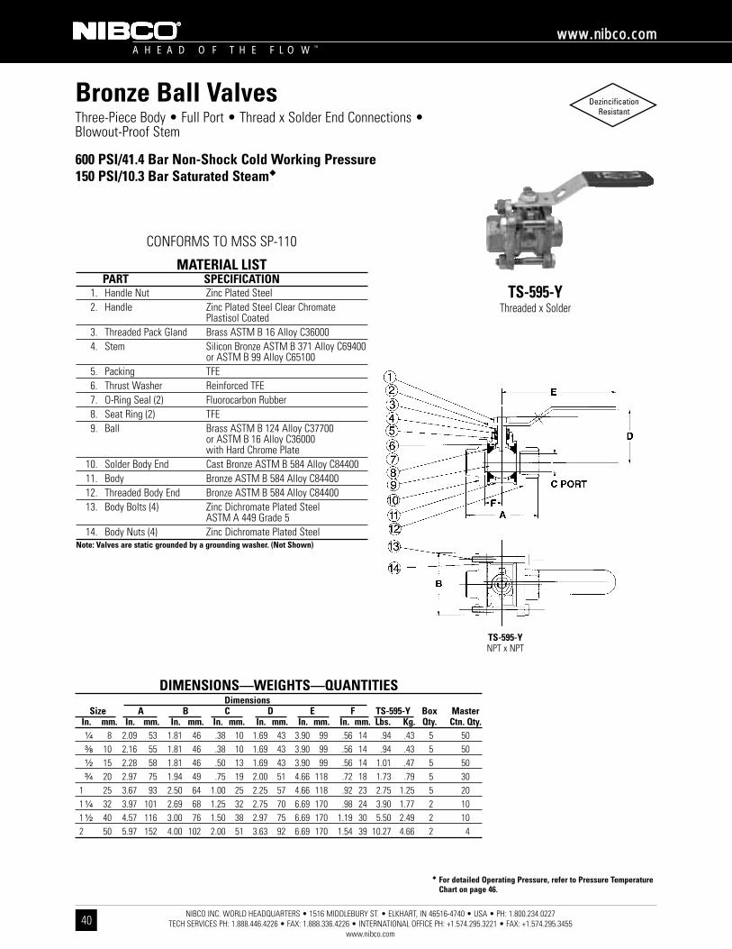
NIBCO INC. WORLD HEADQUARTERS • 1516 MIDDLEBURY ST. • ELKHART, IN 46516-4740 • USA • PH: 1.800.234.0227 TECH SERVICES PH: 1.888.446.4226 • FAX: 1.888.336.4226 • INTERNATIONAL OFFICE PH: +1.574.295.3221 • FAX: +1.574.295.3455
www.nibco.com
A H E A D O F T H E F L O W ™
wwwwww..nniibbccoo..ccoomm
40
Three-Piece Body • Full Port • Thread x Solder End Connections •Blowout-Proof Stem
600 PSI/41.4 Bar Non-Shock Cold Working Pressure150 PSI/10.3 Bar Saturated Steam��
TS-595-YThreaded x Solder
MATERIAL LISTPART SPECIFICATION
1. Handle Nut Zinc Plated Steel 2. Handle Zinc Plated Steel Clear Chromate
Plastisol Coated3. Threaded Pack Gland Brass ASTM B 16 Alloy C360004. Stem Silicon Bronze ASTM B 371 Alloy C69400
or ASTM B 99 Alloy C651005. Packing TFE6. Thrust Washer Reinforced TFE7. O-Ring Seal (2) Fluorocarbon Rubber8. Seat Ring (2) TFE9. Ball Brass ASTM B 124 Alloy C37700
or ASTM B 16 Alloy C36000with Hard Chrome Plate
10. Solder Body End Cast Bronze ASTM B 584 Alloy C8440011. Body Bronze ASTM B 584 Alloy C8440012. Threaded Body End Bronze ASTM B 584 Alloy C8440013. Body Bolts (4) Zinc Dichromate Plated Steel
ASTM A 449 Grade 514. Body Nuts (4) Zinc Dichromate Plated Steel
Note: Valves are static grounded by a grounding washer. (Not Shown)
�� For detailed Operating Pressure, refer to Pressure TemperatureChart on page 46.
DIMENSIONS—WEIGHTS—QUANTITIESDimensions
Size A B C D E F TS-595-Y Box MasterIn. mm. In. mm. In. mm. In. mm. In. mm. In. mm. In. mm. Lbs. Kg. Qty. Ctn. Qty.¹⁄₄ 8 2.09 53 1.81 46 .38 10 1.69 43 3.90 99 .56 14 .94 .43 5 50³⁄₈ 10 2.16 55 1.81 46 .38 10 1.69 43 3.90 99 .56 14 .94 .43 5 50¹⁄₂ 15 2.28 58 1.81 46 .50 13 1.69 43 3.90 99 .56 14 1.01 .47 5 50³⁄₄ 20 2.97 75 1.94 49 .75 19 2.00 51 4.66 118 .72 18 1.73 .79 5 30
1 25 3.67 93 2.50 64 1.00 25 2.25 57 4.66 118 .92 23 2.75 1.25 5 201 ¹⁄₄ 32 3.97 101 2.69 68 1.25 32 2.75 70 6.69 170 .98 24 3.90 1.77 2 101 ¹⁄₂ 40 4.57 116 3.00 76 1.50 38 2.97 75 6.69 170 1.19 30 5.50 2.49 2 102 50 5.97 152 4.00 102 2.00 51 3.63 92 6.69 170 1.54 39 10.27 4.66 2 4
TS-595-YNPT x NPT
CONFORMS TO MSS SP-110
Bronze Ball Valves DezincificationResistant

NIBCO INC. WORLD HEADQUARTERS • 1516 MIDDLEBURY ST. • ELKHART, IN 46516-4740 • USA • PH: 1.800.234.0227 TECH SERVICES PH: 1.888.446.4226 • FAX: 1.888.336.4226 • INTERNATIONAL OFFICE PH: +1.574.295.3221 • FAX: +1.574.295.3455
www.nibco.com
A H E A D O F T H E F L O W ™
wwwwww..nniibbccoo..ccoomm
41
Three-Piece Body • Full Port • Grooved End • Bronze Trim • Blowout-Proof Stem
600 PSI/41.4 Bar Non-Shock Cold Working Pressure150 PSI/10.3 Bar Saturated Steam��
G-595-YGrooved
MATERIAL LISTPART SPECIFICATION
1. Handle Nut Zinc Plated Steel2. Handle Zinc Plated Steel Clear Chromate
Plastisol Coated3. Threaded Pack Gland Brass ASTM B 16 Alloy C360004. Stem Silicon Bronze ASTM B 371 Alloy C69400
or ASTM B 99 Alloy C651005. Body Bronze ASTM B 584 Alloy C844006. Packing TFE7. Body End (2) Bronze ASTM B 584 Alloy C844008. O-Ring Seal (2) Fluorocarbon Rubber9. Seat Ring (2) TFE
10. Ball Brass ASTM B 124 Alloy C37700or ASTM B 16 Alloy C36000with Hard Chrome Plate
11. Thrust Washer Reinforced TFE12. Body Bolts Zinc Dichromate Plated Steel
ASTM A 449 Grade 513. Body Nuts Zinc Dichromate Plated Steel
ASTM A 449 Grade 5Note: Valves are static grounded by a grounding washer. (Not Shown)
�� For detailed Operating Pressure, refer to Pressure TemperatureChart on page 46.
DIMENSIONS—WEIGHTS—QUANTITIESDimensions
Size A B C D E G-595-Y MasterIn. mm. In. mm. In. mm. In. mm. In. mm. In. mm. Lbs. Kg. Ctn. Qty.
1 ¹⁄₂ 40 5.87 149 3.00 76 1.50 38 2.97 75 6.69 170 6.02 2.73 102 50 6.64 169 4.00 102 2.00 51 3.63 92 6.69 170 10.48 4.76 42 ¹⁄₂ 65 7.78 198 5.00 127 2.50 64 4.09 104 8.00 203 18.30 8.30 2
G-595-YGRVD x GRVD
CONFORMS TO MSS SP-110
Bronze Ball Valves DezincificationResistant

NIBCO INC. WORLD HEADQUARTERS • 1516 MIDDLEBURY ST. • ELKHART, IN 46516-4740 • USA • PH: 1.800.234.0227 TECH SERVICES PH: 1.888.446.4226 • FAX: 1.888.336.4226 • INTERNATIONAL OFFICE PH: +1.574.295.3221 • FAX: +1.574.295.3455
www.nibco.com
A H E A D O F T H E F L O W ™
wwwwww..nniibbccoo..ccoomm
42
Three-Piece Body • Full Port • Grooved End • 316SS Trim • Blowout-Proof Stem • Vented Ball
600 PSI/41.4 Bar Non-Shock Cold Working Pressure150 PSI/10.3 Bar Saturated Steam��
G-595-Y-66Grooved
MATERIAL LISTPART SPECIFICATION
1. Handle Nut Stainless Steel 300 Series2. Handle Zinc Plated Steel Clear Chromate
Plastisol Coated3. Threaded Pack Gland Brass ASTM B 16 Alloy C360004. Stem Stainless Steel ASTM A 276 Type 3165. Body Bronze ASTM B 584 Alloy C844006. Packing TFE7. Body End (2) Cast Bronze ASTM B 584 Alloy C844008. O-Ring Seal (2) Fluorocarbon Rubber9. Seat Ring (2) TFE
10. Ball (Vented) Stainless Steel ASTM A 276 Type 316or ASTM A 351 Type CF8M
11. Thrust Washer Reinforced TFE12. Body Bolts Zinc Dichromate Plated Steel
ASTM A 449 Grade 513. Body Nuts Zinc Dichromate Plated Steel
ASTM A 449 Grade 5Note: Valves are static grounded by a grounding washer. (Not Shown)
�� For detailed Operating Pressure, refer to Pressure TemperatureChart on page 46.
DIMENSIONS—WEIGHTS—QUANTITIESDimensions
Size A B C D E G-595-Y-66 MasterIn. mm. In. mm. In. mm. In. mm. In. mm. In. mm. Lbs. Kg. Ctn. Qty.
1 ¹⁄₂ 40 5.87 149 3.00 76 1.50 38 2.97 75 6.69 170 6.02 2.73 102 50 6.64 169 4.00 102 2.00 51 3.63 92 6.69 170 10.48 4.76 42 ¹⁄₂ 65 7.78 198 5.00 127 2.50 64 4.09 104 8.00 203 18.30 8.30 2
G-595-Y-66GRVD x GRVD
CONFORMS TO MSS SP-110
Bronze Ball Valves DezincificationResistant
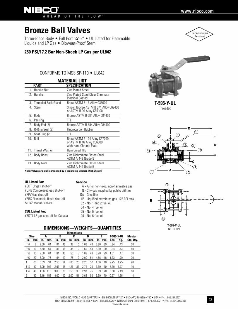
NIBCO INC. WORLD HEADQUARTERS • 1516 MIDDLEBURY ST. • ELKHART, IN 46516-4740 • USA • PH: 1.800.234.0227 TECH SERVICES PH: 1.888.446.4226 • FAX: 1.888.336.4226 • INTERNATIONAL OFFICE PH: +1.574.295.3221 • FAX: +1.574.295.3455
www.nibco.com
A H E A D O F T H E F L O W ™
wwwwww..nniibbccoo..ccoomm
43
Three-Piece Body • Full Port ¹⁄₄"-2" • UL Listed for Flammable Liquids and LP Gas • Blowout-Proof Stem
250 PSI/17.2 Bar Non-Shock LP Gas per UL842
CONFORMS TO MSS SP-110 • UL842
T-595-Y-ULThreaded
MATERIAL LISTPART SPECIFICATION
1. Handle Nut Zinc Plated Steel2. Handle Zinc Plated Steel Clear Chromate
Plastisol Coated3. Threaded Pack Gland Brass ASTM B 16 Alloy C360004. Stem Silicon Bronze ASTM B 371 Alloy C69400
or ASTM B 99 Alloy C651005. Body Bronze ASTM B 584 Alloy C844006. Packing TFE7. Body End (2) Bronze ASTM B 584 Alloy C844008. O-Ring Seal (2) Fluorocarbon Rubber9. Seat Ring (2) TFE
10. Ball Brass ASTM B 124 Alloy C37700or ASTM B 16 Alloy C36000with Hard Chrome Plate
11. Thrust Washer Reinforced TFE12. Body Bolts Zinc Dichromate Plated Steel
ASTM A 449 Grade 513. Body Nuts Zinc Dichromate Plated Steel
ASTM A 449 Grade 5Note: Valves are static grounded by a grounding washer. (Not Shown)
DIMENSIONS—WEIGHTS—QUANTITIESDimensions
Size A B C D E T-595-Y-UL MasterIn. mm. In. mm. In. mm. In. mm. In. mm. In. mm. Lbs. Kg. Ctn. Qty.¹⁄₄ 8 2.50 64 1.81 46 .38 10 1.69 43 3.90 99 .94 .43 50³⁄₈ 10 2.50 64 1.81 46 .38 10 1.69 43 3.90 99 .94 .43 50¹⁄₂ 15 2.50 64 1.81 46 .50 13 1.69 43 3.90 99 1.01 .47 50³⁄₄ 20 3.00 76 1.94 49 .75 19 2.00 51 4.66 118 1.73 .79 30
1 25 3.69 94 2.50 64 1.00 25 2.25 57 4.66 118 2.75 1.25 201 ¹⁄₄ 32 4.09 104 2.69 68 1.25 32 2.75 70 6.69 170 3.90 1.77 101 ¹⁄₂ 40 4.56 116 3.00 76 1.50 38 2.97 75 6.69 170 5.50 2.49 102 50 6.16 156 4.00 102 2.00 51 3.63 92 6.69 170 10.27 4.66 4
T-595-Y-ULNPT x NPT
UL Listed For:YSDT LP gas shut-offYQNZ Compressed gas shut-offYRPV Gas shut-offYRBX Flammable liquid shut-offMHKZ Manual valves
CUL Listed For:YSDT7 LP gas shut-off for Canada
ServiceA - Air or non-toxic, non-flammable gasG - City gas supplied by public utilities
GA - GasolineLP - Liquified petroleum gas, 175 PSI max.02 - No. 1 and 2 fuel oil04 - No. 4 fuel oil05 - No. 5 fuel oil06 - No. 6 fuel oil
Bronze Ball Valves DezincificationResistant
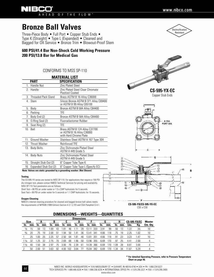
NIBCO INC. WORLD HEADQUARTERS • 1516 MIDDLEBURY ST. • ELKHART, IN 46516-4740 • USA • PH: 1.800.234.0227 TECH SERVICES PH: 1.888.446.4226 • FAX: 1.888.336.4226 • INTERNATIONAL OFFICE PH: +1.574.295.3221 • FAX: +1.574.295.3455
www.nibco.com
A H E A D O F T H E F L O W ™
wwwwww..nniibbccoo..ccoomm
44
Three-Piece Body • Full Port • Copper Stub Ends • Type K (Straight) • Type L (Expanded) • Cleaned and Bagged for OX Service • Bronze Trim • Blowout-Proof Stem
600 PSI/41.4 Bar Non-Shock Cold Working Pressure200 PSI/13.8 Bar for Medical Gas
CS-595-YX-ECCopper Stub Ends
MATERIAL LISTPART SPECIFICATION
1. Handle Nut Zinc Plated Steel2. Handle Zinc Plated Steel Clear Chromate
Plastisol Coated3. Threaded Pack Gland Brass ASTM B 16 Alloy C360004. Stem Silicon Bronze ASTM B 371 Alloy C69400
or ASTM B 99 Alloy C651005. Body Bronze ASTM B 584 Alloy C844006. Packing TFE7. Body End (2) Bronze ASTM B 584 Alloy C844008. O-Ring Seal (2) Fluoroelastomer Rubber9. Seat Ring (2) TFE
10. Ball Brass ASTM B 124 Alloy C37700or ASTM B 16 Alloy C36000with Hard Chrome Plate
11. Ground Washer Stainless Steel ASTM A 167 Type 30412. Thrust Washer Reinforced TFE13. Body Bolts Zinc Dichromate Plated Steel
ASTM A 449 Grade 514. Body Nuts Zinc Dichromate Plated Steel
ASTM A 449 Grade 515. Straight Stub Out (2) 6" Copper Tube Type K16. Expanded Stub Out (2) 6" Copper Tube Type L (Specify EC)
Note: Valves are static grounded by a grounding washer. (Not Shown)
�� For detailed Operating Pressure, refer to Pressure TemperatureChart on page 46.
DIMENSIONS—WEIGHTS—QUANTITIESDimensions
Size A B C D F G H CS-595-YX/EC MasterIn. mm. In. mm. In. mm. In. mm. In. mm. In. mm. In. mm. In. mm. Lbs. Kg. Ctn. Qty.¹⁄₂ 15 .50 13 1.69 43 1.81 46 1.11 28 13.11 333 3.91 99 .50 13 1.22 .55 10³⁄₄ 20 .75 19 2.00 51 1.94 50 1.41 36 13.41 341 4.66 118 .75 19 2.25 1.02 10
1 25 1.00 25 2.25 57 2.50 64 1.81 46 13.81 351 4.66 118 .91 23 3.23 1.47 101 ¹⁄₄ 32 1.25 32 2.75 70 2.69 68 1.96 50 13.96 355 6.69 170 .97 25 4.41 2.00 41 ¹⁄₂ 40 1.50 38 2.97 75 3.00 76 2.39 61 14.39 366 6.69 170 1.09 28 6.61 3.00 42 50 2.00 51 3.63 92 4.00 102 3.04 77 15.04 382 6.69 170 1.34 34 11.67 5.29 4
CS-595-YX/CS-595-YX-ECCSE x CSE
CONFORMS TO MSS SP-110
Bronze Ball Valves
TestingThe CS-595-YX series are tested to MSS SP-110. For applications that require a 150 PSIdry nitrogen test, please contact NIBCO Technical Services for pricing and availability. MSS SP-110 Test parameters are as follows:Shell Test = 80 PSI air under water or 1.5 x CWP hydrostatic for 5 seconds.Seat Test = 80 PSI air under water for 5 seconds or 1.1 CWP hydrostatic for 15 seconds.
Oxygen CleaningNIBCO's internal cleaning procedure for cleaned and bagged bronze ball valves meetsthe requirements of NFPA99 (1999 Edition) Section 4-3.1.2.7(f) and CGA Pamphlet G-4-1.
DezincificationResistant

NIBCO INC. WORLD HEADQUARTERS • 1516 MIDDLEBURY ST. • ELKHART, IN 46516-4740 • USA • PH: 1.800.234.0227 TECH SERVICES PH: 1.888.446.4226 • FAX: 1.888.336.4226 • INTERNATIONAL OFFICE PH: +1.574.295.3221 • FAX: +1.574.295.3455
www.nibco.com
A H E A D O F T H E F L O W ™
wwwwww..nniibbccoo..ccoomm
45
Three-Piece Body • Full Port • 6" Copper Stub Ends • Type K (Straight) • Type L (Expanded) • Cleaned and Bagged for OX Service • 316SS Trim • Blowout-Proof
600 PSI/41.4 Bar Non-Shock Cold Working Pressure200 PSI/13.8 Bar for Medical Gas
CS-595-YX-66-EC(316SS Trim)
Copper Stub Ends
MATERIAL LISTPART SPECIFICATION
1. Handle Nut Zinc Plated Steel2. Handle Zinc Plated Steel Clear Chromate
Plastisol Coated3. Threaded Pack Gland Brass ASTM B 16 Alloy C360004. Stem Stainless Steel ASTM A 276 Type 3165. Body Bronze ASTM B 584 Alloy C844006. Packing TFE7. Body End (2) Bronze ASTM B 584 Alloy C844008. O-Ring Seal (2) Fluoroelastomer Rubber9. Seat Ring (2) TFE
10. Ball Stainless Steel ASTM A 276 Type 316or ASTM A 351 Type CF8M
11. Ground Washer Stainless Steel ASTM A 167 Type 30412. Thrust Washer Reinforced TFE13. Body Bolts Zinc Dichromate Plated Steel
ASTM A 449 Grade 514. Body Nuts Zinc Dichromate Plated Steel
ASTM A 449 Grade 515. Straight Stub Out (2) 6" Copper Tube Type K16. Expanded Stub Out (2) 6" Copper Tube Type L (Specify EC)
Note: Valves are static grounded by a grounding washer. (Not Shown)
�� For detailed Operating Pressure, refer to Pressure TemperatureChart on page 46.
DIMENSIONS—WEIGHTS—QUANTITIESDimensions
Size A B C D F G H CS-595-YX-66/EC MasterIn. mm. In. mm. In. mm. In. mm. In. mm. In. mm. In. mm. In. mm. Lbs. Kg. Ctn. Qty.¹⁄₂ 15 .50 13 1.69 43 1.81 46 1.11 28 13.11 333 3.91 99 .50 13 1.22 .55 10³⁄₄ 20 .75 19 2.00 51 1.94 50 1.41 36 13.41 341 4.66 118 .75 19 2.25 1.02 10
1 25 1.00 25 2.25 57 2.50 64 1.81 46 13.81 351 4.66 118 .91 23 3.23 1.47 101 ¹⁄₄ 32 1.25 32 2.79 40 2.69 68 1.96 50 13.96 355 6.69 170 .97 25 4.41 2.00 41 ¹⁄₂ 40 1.50 38 2.97 75 3.00 76 2.39 61 14.39 366 6.69 170 1.09 28 6.61 3.00 42 50 2.00 51 3.63 92 4.00 102 3.04 77 15.04 382 6.69 170 1.34 34 11.67 5.29 4
CS-595-YX-66/CS-595-YX-66-ECCSE x CSE
CONFORMS TO MSS SP-110
Bronze Ball Valves
TestingThe CS-595-YX series are tested to MSS SP-110. For applications that require a 150 PSIdry nitrogen test, please contact NIBCO Technical Services for pricing and availability. MSS SP-110 Test parameters are as follows:Shell Test = 80 PSI air under water or 1.5 x CWP hydrostatic for 5 seconds.Seat Test = 80 PSI air under water for 5 seconds or 1.1 CWP hydrostatic for 15 seconds.
Oxygen CleaningNIBCO's internal cleaning procedure for cleaned and bagged bronze ball valves meetsthe requirements of NFPA99 (1999 Edition) Section 4-3.1.2.7(f) and CGA Pamphlet G-4-1.
DezincificationResistant

NIBCO INC. WORLD HEADQUARTERS • 1516 MIDDLEBURY ST. • ELKHART, IN 46516-4740 • USA • PH: 1.800.234.0227 TECH SERVICES PH: 1.888.446.4226 • FAX: 1.888.336.4226 • INTERNATIONAL OFFICE PH: +1.574.295.3221 • FAX: +1.574.295.3455
www.nibco.com
A H E A D O F T H E F L O W ™
wwwwww..nniibbccoo..ccoomm
46
Pressure Temperature Ratings
T-585-70-66-STBronze Ball Valves with Carbon Filled TFE Seats
T-560-BR, T/S-580-70, and 585-70Bronze Ball Valves with Reinforced TFE Seats 580 Bronze Ball Valves with TFE Seats
Temperature, C0 38 93 149 204
Temperature, C0 38 93 149 204
T-560-BR, 590, and 595Bronze Ball Valves with Virgin TFE Seats
Temperature, C0 38 93 149 204
Temperature, C0 38 93 149 204 260
401
BBrroonnzzee BBaallll VVaallvveess
Shaded area refers to recommended seat rating.

NIBCO INC. WORLD HEADQUARTERS • 1516 MIDDLEBURY ST. • ELKHART, IN 46516-4740 • USA • PH: 1.800.234.0227 TECH SERVICES PH: 1.888.446.4226 • FAX: 1.888.336.4226 • INTERNATIONAL OFFICE PH: +1.574.295.3221 • FAX: +1.574.295.3455
www.nibco.com
A H E A D O F T H E F L O W ™
wwwwww..nniibbccoo..ccoomm
47
Carbon Steel Ball ValvesOne, Two, and Three-Piece BodyThreaded, Butt or Socket Weld Ends
Carbon Steel Ball Valve Figure Number Key
T-560-CS-R-25-**
K - Socket WeldT - Threaded
TC - Threaded (Investment Cast Carbon Body)
BM - Butt Weld ISO MountKM - Socket Weld ISO MountTM - Threaded ISO Mount
560 - One-Piece Body (Casting)
570 - One-Piece Body (Bar Stock)
580 - Two-Piece BodyConventional Port
585 - Two-Piece Body Full Port
590 - Three-Piece Body Conventional Port
595 - Three-Piece Body Full Port
CS - Carbon Steel
S6 - Stainless Steel
Y - Virgin TFER - Reinforced
TFE
25 - Carbon Steel66 - Stainless Steel
FS - Fire SafeOL - Oval Locking HdleLL - Locking Lever Hdle
OV - Oval Hdle
* This key is a guide only and is not intended to infer that every valve combination will be produced.
End Connection
ValveStyle
BasicMaterial
SeatMaterial
TrimMaterial Options

NIBCO INC. WORLD HEADQUARTERS • 1516 MIDDLEBURY ST. • ELKHART, IN 46516-4740 • USA • PH: 1.800.234.0227 TECH SERVICES PH: 1.888.446.4226 • FAX: 1.888.336.4226 • INTERNATIONAL OFFICE PH: +1.574.295.3221 • FAX: +1.574.295.3455
www.nibco.com
A H E A D O F T H E F L O W ™
wwwwww..nniibbccoo..ccoomm
48
One, Two, and Three-Piece Carbon Steel Ball ValvesIllustrated Index
One-Piece Carbon Steel Ball Valve2000 lb. CWP
Three-Piece Carbon Steel Ball Valve2000 lb. CWP
TM/KM/BM-590-CS-R-66-FS-LLSizes ¹⁄₂" thru 2"
Threaded, Socket or Butt Weld EndsPage 59
Three-Piece Carbon Steel Ball Valve1000 lb. CWP
T/K-595-CS-R-66-LLSizes ¹⁄₄" thru 2"
Threaded or Socket Weld EndsPage 60
Three-Piece Carbon Steel Ball Valve1000 lb. CWP
TM/KM-595-CS-R-66Sizes ¹⁄₄" thru 2"
Threaded or Socket Weld EndsPage 61
Two-Piece Carbon Steel Ball Valve2000 lb. CWP
TC-580-CS-R-25-LL/66-LLSizes ¹⁄₂" thru 2"Threaded EndsPage 55, 56
Two-Piece Bar Stock Carbon Steel Ball Valve2000 lb. CWP ¹⁄₄"-1"
1500 lb. CWP 1¹⁄₄"-2"
T-580-CS-R-25/66Sizes ¹⁄₄" thru 2"Threaded EndsPage 57, 58
T-560-CS-R-25/66-FSSizes ¹⁄₄" thru 2"Threaded EndsPages 49-52
One-Piece Bar Stock Carbon Steel Ball Valve2000 lb. CWP ¹⁄₂"-1"1500 lb. CWP 1¹⁄₄"-2"
T-570-CS-R-25/66Sizes ¹⁄₂" thru 2"Threaded EndsPage 53, 54

�� For detailed Operating Pressure, refer to Pressure TemperatureChart on pages 71 and 72.
NIBCO INC. WORLD HEADQUARTERS • 1516 MIDDLEBURY ST. • ELKHART, IN 46516-4740 • USA • PH: 1.800.234.0227 TECH SERVICES PH: 1.888.446.4226 • FAX: 1.888.336.4226 • INTERNATIONAL OFFICE PH: +1.574.295.3221 • FAX: +1.574.295.3455
www.nibco.com
A H E A D O F T H E F L O W ™
wwwwww..nniibbccoo..ccoomm
49
One-Piece Body • Reduced Port • Blowout-Proof Stem •CS Trim • Vented Ball
T-560-CS-R-25-LLThreaded
MATERIAL LISTPART SPECIFICATION
1. Body Carbon Steel ASTM A 216 Grade WCB2. Body Insert Carbon Steel ASTM A 216 Grade WCB3. Ball (Vented) Stainless Steel ASTM A 276 Type 304
or ASTM A 351 Type CF8M4. Stem Carbon Steel ASTM A 108 Type 10185. Seat Reinforced TFE6. Thrust Washer Reinforced TFE (Carbon 25% + Teflon 75%)7. 1Stem Packing Graphoil8. Threaded Pack Gland Carbon Steel ASTM A 108 Type 1045 9. Handle Nut Carbon Steel ASTM A 283
10. 2Handle Carbon Steel ASTM A 283 1 ¹⁄₄"-³⁄₄" one each, 1"-2" two each.2 Shown with lock handle.
NOTE: Valves are static grounded by thrust washer and packing.
DIMENSIONS—WEIGHTS—QUANTITIESDimensions
Size A B D L H T-560-CS-R-25-LL MasterIn. mm. In. mm. In. mm. In. mm. In. mm. In. mm. Lbs. Kg. Ctn. Qty.¹⁄₄ 8 2.28 58 1.10 28 .31 8 4.29 109 1.97 50 .20 .09 50³⁄₈ 10 2.28 58 1.10 28 .31 8 4.29 109 1.97 50 .31 .14 50¹⁄₂ 15 2.60 66 1.10 28 .31 8 4.29 109 1.97 50 .66 .30 50³⁄₄ 20 2.83 72 1.34 34 .47 12 4.29 109 2.20 56 .93 .42 50
1 25 3.23 82 1.61 41 .62 16 5.75 146 2.56 65 1.59 .72 401 ¹⁄₄ 32 3.54 90 1.97 50 .81 21 5.75 146 2.76 70 2.12 .96 201 ¹⁄₂ 40 3.86 98 2.24 57 1.00 25 7.40 188 3.29 84 3.22 1.46 202 50 4.33 110 2.76 70 1.25 32 7.40 188 3.49 89 4.65 2.11 10
T-560-CS-R-25-LLNPT x NPT
CONFORMS TO MSS SP-110 • NACE MRO175 • WW-V-35C, TYPE II, CLASS CS, STYLE 3
Carbon Steel Ball Valves
2000 PSI/138 Bar Non-Shock Cold Working Pressure

2000 PSI/138 Bar Non-Shock Cold Working Pressure
�� For detailed Operating Pressure, refer to Pressure TemperatureChart on pages 71 and 72.
NIBCO INC. WORLD HEADQUARTERS • 1516 MIDDLEBURY ST. • ELKHART, IN 46516-4740 • USA • PH: 1.800.234.0227 TECH SERVICES PH: 1.888.446.4226 • FAX: 1.888.336.4226 • INTERNATIONAL OFFICE PH: +1.574.295.3221 • FAX: +1.574.295.3455
www.nibco.com
A H E A D O F T H E F L O W ™
wwwwww..nniibbccoo..ccoomm
50
One-Piece Body • Reduced Port • Blowout-Proof Stem •CS Trim • Vented Ball • Fire Safe
CONFORMS TO API-607 FOURTH EDITION FIRE SAFE •MSS SP-110 • NACE MRO175 •
WW-V-35C, TYPE II, CLASS CS, STYLE 3
T-560-CS-R-25-FS-LLThreaded
MATERIAL LISTPART SPECIFICATION
1. Body Carbon Steel ASTM A 216 Grade WCB2. Body Insert Carbon Steel ASTM A 216 Grade WCB3. Ball (Vented) Stainless Steel ASTM A 276 Type 304
or ASTM A 351 Type CF8M4. Stem Carbon Steel ASTM A 108 Type 10185. Seat Reinforced TFE6. Thrust Washer Reinforced TFE (Carbon 25% + Teflon 75%)7. 1Stem Packing Graphoil8. Threaded Pack Gland Carbon Steel ASTM A 108 Type 10459. Handle Nut Carbon Steel ASTM A 283
10. 2Handle Carbon Steel ASTM A 283 1 ¹⁄₄"-³⁄₄" one each, 1"-2" two each.2 Shown with lock handle.
NOTE: Valves are static grounded by thrust washer and packing.
DIMENSIONS—WEIGHTS—QUANTITIESDimensions
Size A B D L H T-560-CS-R-25-FS-LL MasterIn. mm. In. mm. In. mm. In. mm. In. mm. In. mm. Lbs. Kg. Ctn. Qty.¹⁄₄ 8 2.28 58 1.10 28 .31 8 4.29 109 1.97 50 .20 .09 50³⁄₈ 10 2.28 58 1.10 28 .31 8 4.29 109 1.97 50 .31 .14 50¹⁄₂ 15 2.60 66 1.10 28 .31 8 4.29 109 1.97 50 .66 .30 50³⁄₄ 20 2.83 72 1.34 34 .47 12 4.29 109 2.20 56 .93 .42 50
1 25 3.23 82 1.61 41 .62 16 5.75 146 2.56 65 1.59 .72 401 ¹⁄₄ 32 3.54 90 1.97 50 .81 21 5.75 146 2.76 70 2.12 .96 201 ¹⁄₂ 40 3.86 98 2.24 57 1.00 25 7.40 188 3.29 84 3.22 1.46 202 50 4.33 110 2.76 70 1.25 32 7.40 188 3.49 89 4.65 2.11 10
T-560-CS-R-25-FS-LLNPT x NPT
Carbon Steel Ball Valves
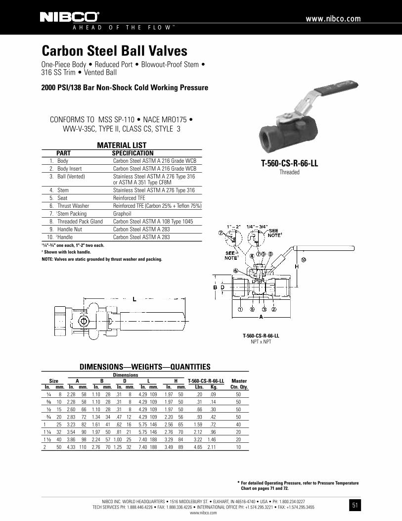
�� For detailed Operating Pressure, refer to Pressure TemperatureChart on pages 71 and 72.
2000 PSI/138 Bar Non-Shock Cold Working Pressure
NIBCO INC. WORLD HEADQUARTERS • 1516 MIDDLEBURY ST. • ELKHART, IN 46516-4740 • USA • PH: 1.800.234.0227 TECH SERVICES PH: 1.888.446.4226 • FAX: 1.888.336.4226 • INTERNATIONAL OFFICE PH: +1.574.295.3221 • FAX: +1.574.295.3455
www.nibco.com
A H E A D O F T H E F L O W ™
wwwwww..nniibbccoo..ccoomm
51
One-Piece Body • Reduced Port • Blowout-Proof Stem •316 SS Trim • Vented Ball
T-560-CS-R-66-LLThreaded
MATERIAL LISTPART SPECIFICATION
1. Body Carbon Steel ASTM A 216 Grade WCB2. Body Insert Carbon Steel ASTM A 216 Grade WCB3. Ball (Vented) Stainless Steel ASTM A 276 Type 316
or ASTM A 351 Type CF8M4. Stem Stainless Steel ASTM A 276 Type 3165. Seat Reinforced TFE6. Thrust Washer Reinforced TFE (Carbon 25% + Teflon 75%)7. 1Stem Packing Graphoil8. Threaded Pack Gland Carbon Steel ASTM A 108 Type 10459. Handle Nut Carbon Steel ASTM A 283
10. 2Handle Carbon Steel ASTM A 283 1¹⁄₄"-³⁄₄" one each, 1"-2" two each.2 Shown with lock handle.
NOTE: Valves are static grounded by thrust washer and packing.
DIMENSIONS—WEIGHTS—QUANTITIESDimensions
Size A B D L H T-560-CS-R-66-LL MasterIn. mm. In. mm. In. mm. In. mm. In. mm. In. mm. Lbs. Kg. Ctn. Qty.¹⁄₄ 8 2.28 58 1.10 28 .31 8 4.29 109 1.97 50 .20 .09 50³⁄₈ 10 2.28 58 1.10 28 .31 8 4.29 109 1.97 50 .31 .14 50¹⁄₂ 15 2.60 66 1.10 28 .31 8 4.29 109 1.97 50 .66 .30 50³⁄₄ 20 2.83 72 1.34 34 .47 12 4.29 109 2.20 56 .93 .42 50
1 25 3.23 82 1.61 41 .62 16 5.75 146 2.56 65 1.59 .72 401 ¹⁄₄ 32 3.54 90 1.97 50 .81 21 5.75 146 2.76 70 2.12 .96 201 ¹⁄₂ 40 3.86 98 2.24 57 1.00 25 7.40 188 3.29 84 3.22 1.46 202 50 4.33 110 2.76 70 1.25 32 7.40 188 3.49 89 4.65 2.11 10
T-560-CS-R-66-LLNPT x NPT
CONFORMS TO MSS SP-110 • NACE MRO175 • WW-V-35C, TYPE II, CLASS CS, STYLE 3
Carbon Steel Ball Valves
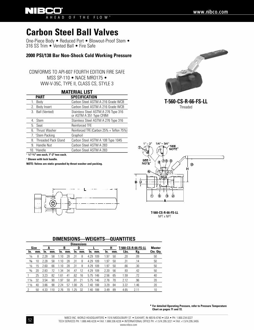
�� For detailed Operating Pressure, refer to Pressure TemperatureChart on pages 71 and 72.
NIBCO INC. WORLD HEADQUARTERS • 1516 MIDDLEBURY ST. • ELKHART, IN 46516-4740 • USA • PH: 1.800.234.0227 TECH SERVICES PH: 1.888.446.4226 • FAX: 1.888.336.4226 • INTERNATIONAL OFFICE PH: +1.574.295.3221 • FAX: +1.574.295.3455
www.nibco.com
A H E A D O F T H E F L O W ™
wwwwww..nniibbccoo..ccoomm
52
Carbon Steel Ball ValvesOne-Piece Body • Reduced Port • Blowout-Proof Stem •316 SS Trim • Vented Ball • Fire Safe
2000 PSI/138 Bar Non-Shock Cold Working Pressure
CONFORMS TO API-607 FOURTH EDITION FIRE SAFEMSS SP-110 • NACE MRO175 •
WW-V-35C, TYPE II, CLASS CS, STYLE 3
T-560-CS-R-66-FS-LLThreaded
MATERIAL LISTPART SPECIFICATION
1. Body Carbon Steel ASTM A 216 Grade WCB2. Body Insert Carbon Steel ASTM A 216 Grade WCB3. Ball (Vented) Stainless Steel ASTM A 276 Type 316
or ASTM A 351 Type CF8M4. Stem Stainless Steel ASTM A 276 Type 3165. Seat Reinforced TFE6. Thrust Washer Reinforced TFE (Carbon 25% + Teflon 75%)7. 1Stem Packing Graphoil8. Threaded Pack Gland Carbon Steel ASTM A 108 Type 10459. Handle Nut Carbon Steel ASTM A 283
10. 2Handle Carbon Steel ASTM A 283 1 ¹⁄₄"-³⁄₄" one each, 1"-2" two each.2 Shown with lock handle.
NOTE: Valves are static grounded by thrust washer and packing.
DIMENSIONS—WEIGHTS—QUANTITIESDimensions
Size A B D L H T-560-CS-R-66-FS-LL MasterIn. mm. In. mm. In. mm. In. mm. In. mm. In. mm. Lbs. Kg. Ctn. Qty.¹⁄₄ 8 2.28 58 1.10 28 .31 8 4.29 109 1.97 50 .20 .09 50³⁄₈ 10 2.28 58 1.10 28 .31 8 4.29 109 1.97 50 .31 .14 50¹⁄₂ 15 2.60 66 1.10 28 .31 8 4.29 109 1.97 50 .66 .30 50³⁄₄ 20 2.83 72 1.34 34 .47 12 4.29 109 2.20 56 .93 .42 50
1 25 3.23 82 1.61 41 .62 16 5.75 146 2.56 65 1.59 .72 401 ¹⁄₄ 32 3.54 90 1.97 50 .81 21 5.75 146 2.76 70 2.12 .96 201 ¹⁄₂ 40 3.86 98 2.24 57 1.00 25 7.40 188 3.29 84 3.22 1.46 202 50 4.33 110 2.76 70 1.25 32 7.40 188 3.49 89 4.65 2.11 10
T-560-CS-R-66-FS-LLNPT x NPT
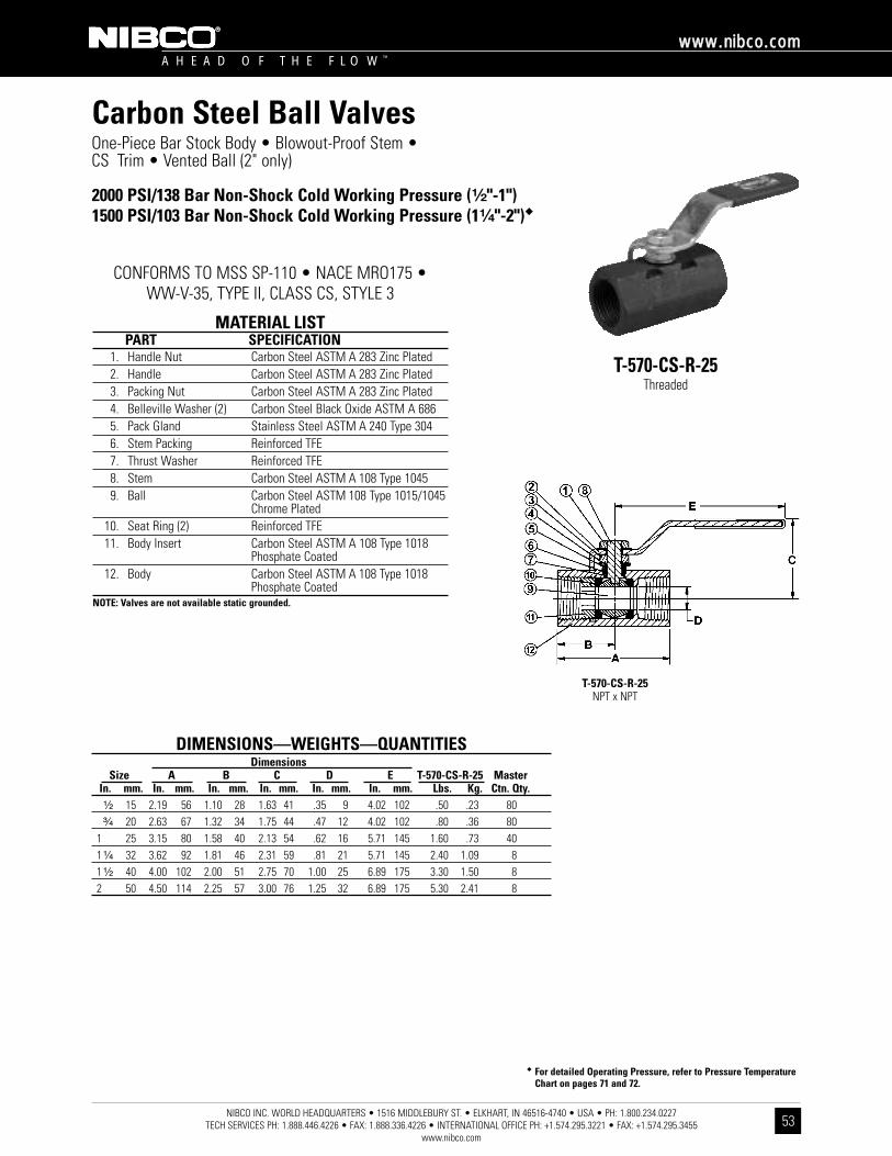
�� For detailed Operating Pressure, refer to Pressure TemperatureChart on pages 71 and 72.
NIBCO INC. WORLD HEADQUARTERS • 1516 MIDDLEBURY ST. • ELKHART, IN 46516-4740 • USA • PH: 1.800.234.0227 TECH SERVICES PH: 1.888.446.4226 • FAX: 1.888.336.4226 • INTERNATIONAL OFFICE PH: +1.574.295.3221 • FAX: +1.574.295.3455
www.nibco.com
A H E A D O F T H E F L O W ™
wwwwww..nniibbccoo..ccoomm
53
Carbon Steel Ball ValvesOne-Piece Bar Stock Body • Blowout-Proof Stem • CS Trim • Vented Ball (2" only)
2000 PSI/138 Bar Non-Shock Cold Working Pressure (¹⁄₂"-1")1500 PSI/103 Bar Non-Shock Cold Working Pressure (1¹⁄₄"-2")��
CONFORMS TO MSS SP-110 • NACE MRO175 • WW-V-35, TYPE II, CLASS CS, STYLE 3
T-570-CS-R-25Threaded
MATERIAL LISTPART SPECIFICATION
1. Handle Nut Carbon Steel ASTM A 283 Zinc Plated2. Handle Carbon Steel ASTM A 283 Zinc Plated3. Packing Nut Carbon Steel ASTM A 283 Zinc Plated4. Belleville Washer (2) Carbon Steel Black Oxide ASTM A 6865. Pack Gland Stainless Steel ASTM A 240 Type 3046. Stem Packing Reinforced TFE7. Thrust Washer Reinforced TFE8. Stem Carbon Steel ASTM A 108 Type 1045 9. Ball Carbon Steel ASTM 108 Type 1015/1045
Chrome Plated10. Seat Ring (2) Reinforced TFE11. Body Insert Carbon Steel ASTM A 108 Type 1018
Phosphate Coated12. Body Carbon Steel ASTM A 108 Type 1018
Phosphate CoatedNOTE: Valves are not available static grounded.
DIMENSIONS—WEIGHTS—QUANTITIESDimensions
Size A B C D E T-570-CS-R-25 MasterIn. mm. In. mm. In. mm. In. mm. In. mm. In. mm. Lbs. Kg. Ctn. Qty.¹⁄₂ 15 2.19 56 1.10 28 1.63 41 .35 9 4.02 102 .50 .23 80³⁄₄ 20 2.63 67 1.32 34 1.75 44 .47 12 4.02 102 .80 .36 80
1 25 3.15 80 1.58 40 2.13 54 .62 16 5.71 145 1.60 .73 401 ¹⁄₄ 32 3.62 92 1.81 46 2.31 59 .81 21 5.71 145 2.40 1.09 81 ¹⁄₂ 40 4.00 102 2.00 51 2.75 70 1.00 25 6.89 175 3.30 1.50 82 50 4.50 114 2.25 57 3.00 76 1.25 32 6.89 175 5.30 2.41 8
T-570-CS-R-25NPT x NPT

�� For detailed Operating Pressure, refer to Pressure TemperatureChart on pages 71 and 72.
NIBCO INC. WORLD HEADQUARTERS • 1516 MIDDLEBURY ST. • ELKHART, IN 46516-4740 • USA • PH: 1.800.234.0227 TECH SERVICES PH: 1.888.446.4226 • FAX: 1.888.336.4226 • INTERNATIONAL OFFICE PH: +1.574.295.3221 • FAX: +1.574.295.3455
www.nibco.com
A H E A D O F T H E F L O W ™
wwwwww..nniibbccoo..ccoomm
54
Carbon Steel Ball ValvesOne-Piece Bar Stock Body • Blowout-Proof Stem • 316SS Trim • Vented Ball (2" Only)
2000 PSI/138 Bar Non-Shock Cold Working Pressure (¹⁄₂"-1")1500 PSI/103 Bar Non-Shock Cold Working Pressure (1¹⁄₄"-2")��
CONFORMS TO MSS SP-110 • NACE MRO175 • WW-V-35C, TYPE II, CLASS CS, STYLE 3
T-570-CS-R-66Threaded
Reinforced TFE Seats and Seals with SS Trim
MATERIAL LISTPART SPECIFICATION
1. Handle Nut Carbon Steel ASTM A 283 Zinc Plated2. Handle Carbon Steel ASTM A 283 Zinc Plated3. Packing Nut Carbon Steel ASTM A 283 Zinc Plated4. Belleville Washer (2) Carbon Steel Black Oxide ASTM A 6865. Pack Gland Stainless Steel ASTM A 240 Type 3046. Stem Packing Reinforced TFE7. Thrust Washer Reinforced TFE8. Stem Stainless Steel ASTM A 276 Type 3169. Ball Stainless Steel ASTM A 276 Type 316
or ASTM A 351 Type CF8M10. Seat Ring (2) Reinforced TFE11. Body Insert Carbon Steel ASTM A 108 Type 1018
Phosphate Coated12. Body Carbon Steel ASTM A 108 Type 1018
Phosphate CoatedNOTE: Valves are not available static grounded.
DIMENSIONS—WEIGHTS—QUANTITIESDimensions
Size A B C D E T-570-CS-R-66 MasterIn. mm. In. mm. In. mm. In. mm. In. mm. In. mm. Lbs. Kg. Ctn. Qty.¹⁄₂ 15 2.19 56 1.10 28 1.63 41 .35 9 4.02 102 .50 .23 80³⁄₄ 20 2.63 67 1.32 34 1.75 44 .47 12 4.02 102 .80 .36 80
1 25 3.15 80 1.58 40 2.13 54 .62 16 5.71 145 1.60 .74 401 ¹⁄₄ 32 3.62 92 1.81 46 2.31 59 .81 21 5.71 145 2.40 1.09 81 ¹⁄₂ 40 4.00 102 2.00 51 2.75 70 1.00 25 6.89 175 3.30 1.50 82 50 4.50 114 2.25 57 3.00 76 1.25 32 6.89 175 5.30 2.41 8
T-570-CS-R-66NPT x NPT
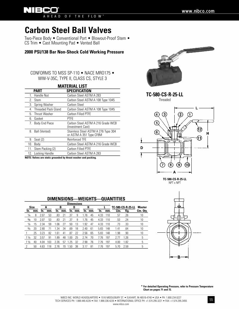
NIBCO INC. WORLD HEADQUARTERS • 1516 MIDDLEBURY ST. • ELKHART, IN 46516-4740 • USA • PH: 1.800.234.0227 TECH SERVICES PH: 1.888.446.4226 • FAX: 1.888.336.4226 • INTERNATIONAL OFFICE PH: +1.574.295.3221 • FAX: +1.574.295.3455
www.nibco.com
A H E A D O F T H E F L O W ™
wwwwww..nniibbccoo..ccoomm
55
Two-Piece Body • Conventional Port • Blowout-Proof Stem •CS Trim • Cast Mounting Pad • Vented Ball
CONFORMS TO MSS SP-110 • NACE MRO175 • WW-V-35C, TYPE II, CLASS CS, STYLE 3
TC-580-CS-R-25-LLThreaded
MATERIAL LISTPART SPECIFICATION
1. Handle Nut Carbon Steel ASTM A 283 2. Stem Carbon Steel ASTM A 108 Type 10453. Spring Washer Carbon Steel4. Threaded Pack Gland Carbon Steel ASTM A 108 Type 10455. Thrust Washer Carbon Filled PTFE6. Gasket PTFE7. Body End Piece Carbon Steel ASTM A 216 Grade WCB
(Investment Cast)8. Ball (Vented) Stainless Steel ASTM A 276 Type 304
or ASTM A 351 Type CF8M9. Seat (2) Reinforced TFE
10. Body Carbon Steel ASTM A 216 Grade WCB11. Stem Packing (2) Carbon Filled PTFE12. Locking Handle Carbon Steel ASTM A 283
NOTE: Valves are static grounded by thrust washer and packing.
�� For detailed Operating Pressure, refer to Pressure TemperatureChart on pages 71 and 72.
DIMENSIONS—WEIGHTS—QUANTITIESDimensions
Size A B D H L TC-580-CS-R-25-LL MasterIn. mm. In. mm. In. mm. In. mm. In. mm. In. mm. Lbs. Kg. Ctn. Qty.¹⁄₄ 8 2.07 53 .83 21 .37 9 1.76 45 4.33 110 .57 .26 10³⁄₈ 10 2.07 53 .83 21 .37 9 1.76 45 4.33 110 .53 .24 10¹⁄₂ 15 2.34 59 1.06 27 .50 13 1.92 47 4.33 110 .73 .33 10³⁄₄ 20 2.80 71 1.34 34 .69 18 2.40 61 5.83 148 1.41 .64 10
1 25 3.23 82 1.61 41 .87 22 2.56 65 5.83 148 1.98 .90 101 ¹⁄₄ 32 3.57 91 1.89 48 1.00 25 2.74 70 7.76 197 2.77 1.26 51 ¹⁄₂ 40 4.04 103 2.26 57 1.25 32 2.98 76 7.76 197 4.00 1.82 52 50 4.63 118 2.76 70 1.50 38 3.17 81 7.76 197 5.70 2.59 5
TC-580-CS-R-25-LLNPT x NPT
Carbon Steel Ball Valves
2000 PSI/138 Bar Non-Shock Cold Working Pressure

�� For detailed Operating Pressure, refer to Pressure TemperatureChart on pages 71 and 72.
NIBCO INC. WORLD HEADQUARTERS • 1516 MIDDLEBURY ST. • ELKHART, IN 46516-4740 • USA • PH: 1.800.234.0227 TECH SERVICES PH: 1.888.446.4226 • FAX: 1.888.336.4226 • INTERNATIONAL OFFICE PH: +1.574.295.3221 • FAX: +1.574.295.3455
www.nibco.com
A H E A D O F T H E F L O W ™
wwwwww..nniibbccoo..ccoomm
56
Two-Piece Body • Conventional Port • Blowout-Proof Stem •316 SS Trim • Cast Mounting Pad • Vented Ball
CONFORMS TO MSS SP-110 • NACE MRO175 • WW-V-35C, TYPE II, CLASS CS, STYLE 3
TC-580-CS-R-66-LLThreaded
MATERIAL LISTPART SPECIFICATION
1. Handle Nut Carbon Steel ASTM A 283 2. Stem Stainless Steel ASTM A 276 Type 3163. Spring Washer Carbon Steel 4. Threaded Pack Gland Carbon Steel ASTM A 108 Type 10455. Thrust Washer Carbon Filled PTFE6. Gasket PTFE7. Body End Piece Carbon Steel ASTM A 216 Grade WCB
(Investment Cast)8. Ball (Vented) Stainless Steel ASTM A 276 Type 316
or ASTM A 351 Type CF8M9. Seat (2) Reinforced TFE
10. Body Carbon Steel ASTM A 216 Grade WCB11. Stem Packing (2) Carbon Filled PTFE12. Locking Handle Carbon Steel ASTM A 283
NOTE: Valves are static grounded by thrust washer and packing.
DIMENSIONS—WEIGHTS—QUANTITIESDimensions
Size A B D L H TC-580-CS-R-66-LL MasterIn. mm. In. mm. In. mm. In. mm. In. mm. In. mm. Lbs. Kg. Ctn. Qty.¹⁄₄ 8 2.07 53 .90 23 .37 9 1.76 45 4.33 110 .57 .26 10³⁄₈ 10 2.07 53 .90 23 .37 9 1.76 45 4.33 110 .53 .24 10¹⁄₂ 15 2.34 59 1.06 27 .50 13 1.92 49 4.33 110 .73 .33 10³⁄₄ 20 2.80 71 1.34 34 .69 18 2.40 61 5.83 148 1.41 .64 10
1 25 3.23 82 1.61 41 .87 22 2.56 65 5.83 148 1.98 .90 101 ¹⁄₄ 32 3.57 91 1.89 48 1.00 25 2.74 70 7.76 197 2.77 1.26 51 ¹⁄₂ 40 4.04 103 2.26 57 1.25 32 2.98 76 7.76 197 4.00 1.82 52 50 4.63 118 2.76 70 1.50 38 3.17 81 7.76 197 5.70 2.59 5
TC-580-CS-R-66-LLNPT x NPT
Carbon Steel Ball Valves
2000 PSI/138 Bar Non-Shock Cold Working Pressure
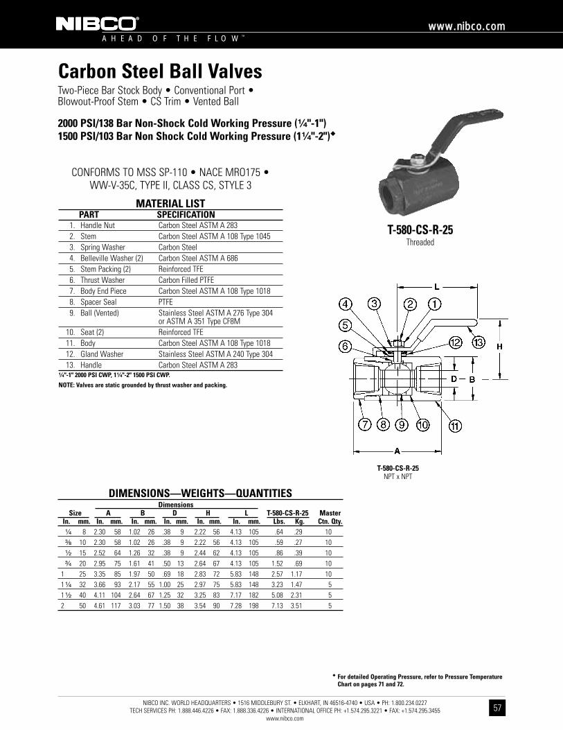
�� For detailed Operating Pressure, refer to Pressure TemperatureChart on pages 71 and 72.
NIBCO INC. WORLD HEADQUARTERS • 1516 MIDDLEBURY ST. • ELKHART, IN 46516-4740 • USA • PH: 1.800.234.0227 TECH SERVICES PH: 1.888.446.4226 • FAX: 1.888.336.4226 • INTERNATIONAL OFFICE PH: +1.574.295.3221 • FAX: +1.574.295.3455
www.nibco.com
A H E A D O F T H E F L O W ™
wwwwww..nniibbccoo..ccoomm
57
Carbon Steel Ball ValvesTwo-Piece Bar Stock Body • Conventional Port • Blowout-Proof Stem • CS Trim • Vented Ball
2000 PSI/138 Bar Non-Shock Cold Working Pressure (¹⁄₄"-1")1500 PSI/103 Bar Non Shock Cold Working Pressure (1¹⁄₄"-2")��
CONFORMS TO MSS SP-110 • NACE MRO175 • WW-V-35C, TYPE II, CLASS CS, STYLE 3
T-580-CS-R-25Threaded
MATERIAL LISTPART SPECIFICATION
1. Handle Nut Carbon Steel ASTM A 283 2. Stem Carbon Steel ASTM A 108 Type 10453. Spring Washer Carbon Steel4. Belleville Washer (2) Carbon Steel ASTM A 6865. Stem Packing (2) Reinforced TFE6. Thrust Washer Carbon Filled PTFE7. Body End Piece Carbon Steel ASTM A 108 Type 10188. Spacer Seal PTFE9. Ball (Vented) Stainless Steel ASTM A 276 Type 304
or ASTM A 351 Type CF8M10. Seat (2) Reinforced TFE11. Body Carbon Steel ASTM A 108 Type 101812. Gland Washer Stainless Steel ASTM A 240 Type 30413. Handle Carbon Steel ASTM A 283
¹⁄₄"-1" 2000 PSI CWP, 1¹⁄₄"-2" 1500 PSI CWP.
NOTE: Valves are static grounded by thrust washer and packing.
DIMENSIONS—WEIGHTS—QUANTITIESDimensions
Size A B D H L T-580-CS-R-25 MasterIn. mm. In. mm. In. mm. In. mm. In. mm. In. mm. Lbs. Kg. Ctn. Qty.¹⁄₄ 8 2.30 58 1.02 26 .38 9 2.22 56 4.13 105 .64 .29 10³⁄₈ 10 2.30 58 1.02 26 .38 9 2.22 56 4.13 105 .59 .27 10¹⁄₂ 15 2.52 64 1.26 32 .38 9 2.44 62 4.13 105 .86 .39 10³⁄₄ 20 2.95 75 1.61 41 .50 13 2.64 67 4.13 105 1.52 .69 10
1 25 3.35 85 1.97 50 .69 18 2.83 72 5.83 148 2.57 1.17 101 ¹⁄₄ 32 3.66 93 2.17 55 1.00 25 2.97 75 5.83 148 3.23 1.47 51 ¹⁄₂ 40 4.11 104 2.64 67 1.25 32 3.25 83 7.17 182 5.08 2.31 52 50 4.61 117 3.03 77 1.50 38 3.54 90 7.28 198 7.13 3.51 5
T-580-CS-R-25NPT x NPT
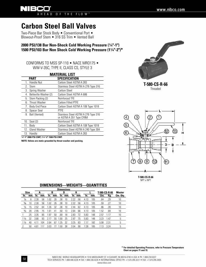
�� For detailed Operating Pressure, refer to Pressure TemperatureChart on pages 71 and 72.
NIBCO INC. WORLD HEADQUARTERS • 1516 MIDDLEBURY ST. • ELKHART, IN 46516-4740 • USA • PH: 1.800.234.0227 TECH SERVICES PH: 1.888.446.4226 • FAX: 1.888.336.4226 • INTERNATIONAL OFFICE PH: +1.574.295.3221 • FAX: +1.574.295.3455
www.nibco.com
A H E A D O F T H E F L O W ™
wwwwww..nniibbccoo..ccoomm
58
Carbon Steel Ball ValvesTwo-Piece Bar Stock Body • Conventional Port •Blowout-Proof Stem • 316 SS Trim • Vented Ball
2000 PSI/138 Bar Non-Shock Cold Working Pressure (¹⁄₄"-1")1500 PSI/103 Bar Non Shock Cold Working Pressure (1¹⁄₄"-2")��
CONFORMS TO MSS SP-110 • NACE MRO175 • WW-V-35C, TYPE II, CLASS CS, STYLE 3
T-580-CS-R-66Threaded
MATERIAL LISTPART SPECIFICATION
1. Handle Nut Carbon Steel ASTM A 283 2. Stem Stainless Steel ASTM A 276 Type 3163. Spring Washer Carbon Steel4. Belleville Washer (2) Carbon Steel ASTM A 6865. Stem Packing (2) Reinforced TFE6. Thrust Washer Carbon Filled PTFE7. Body End Piece Carbon Steel ASTM A 108 Type 10188. Spacer Seal PTFE9. Ball (Vented) Stainless Steel ASTM A 276 Type 316
or ASTM A 351 Type CF8M10. Seat (2) Reinforced TFE11. Body Carbon Steel ASTM A 108 Type 101812. Gland Washer Stainless Steel ASTM A 240 Type 30413. Handle Carbon Steel ASTM A 283
¹⁄₄"-1" 2000 PSI CWP, 1¹⁄₄"-2" 1500 PSI CWP.
NOTE: Valves are static grounded by thrust washer and packing.
DIMENSIONS—WEIGHTS—QUANTITIESDimensions
Size A B D H L T-580-CS-R-66 MasterIn. mm. In. mm. In. mm. In. mm. In. mm. In. mm. Lbs. Kg. Ctn. Qty.¹⁄₄ 8 2.30 58 1.02 26 .38 10 2.22 56 4.13 105 .64 .29 10³⁄₈ 10 2.30 58 1.02 26 .38 10 2.22 56 4.13 105 .59 .27 10¹⁄₂ 15 2.52 64 1.26 32 .38 10 2.44 62 4.13 105 .86 .39 10³⁄₄ 20 2.95 75 1.61 41 .50 13 2.64 66 4.13 105 1.52 .69 10
1 25 3.35 85 1.97 50 .69 18 2.83 72 5.83 148 2.57 1.17 101 ¹⁄₄ 32 3.66 93 2.17 55 1.00 25 2.97 75 5.83 148 3.23 1.47 51 ¹⁄₂ 40 4.11 104 2.64 67 1.25 32 3.25 83 7.17 182 5.08 2.31 52 50 4.61 117 3.03 77 1.50 38 3.54 90 7.28 185 7.13 3.24 5
T-580-CS-R-66NPT x NPT

�� For detailed Operating Pressure, refer to Pressure Temperature Chart on pages 71 and 72.
DIMENSIONS—WEIGHTS—QUANTITIESDimensions
H J K Socket ButtG Socket Socket Butt Threaded Weld Weld
Size A B C D E F Thread Flange Weld Weld Weld Weight Weight WeightIn. mm. In. mm. In. mm. In. mm. In. mm. In. mm. In. mm. Tap Type In. mm. In mm. In. mm. Lbs. Kg. Lbs. Kg. Lbs. Kg.¹⁄₂ 15 2.72 69 2.47 63 4.07 103 .43 11 .12 3 1.00 25 M5 F03 .86 22 .38 10 .84 21 1.80 .82 1.70 .78 1.60 .73³⁄₄ 20 2.94 75 2.70 69 4.07 103 .57 14 .12 3 1.00 25 M5 F03 1.08 27 .50 13 1.05 27 2.40 1.09 2.30 1.05 2.20 1.00
1 25 3.50 89 3.19 81 4.92 125 .81 21 .18 5 1.17 30 M5 F04 1.34 34 .50 13 1.32 34 3.80 1.73 3.60 1.64 3.50 1.591 ¹⁄₄ 32 3.90 99 3.64 92 5.91 150 .98 25 .20 5 1.17 30 M5 F04 1.69 43 .50 13 1.66 42 5.90 2.68 5.70 2.59 5.60 2.551 ¹⁄₂ 40 4.42 112 3.88 99 7.68 195 1.25 32 .23 8 1.39 35 M6 F05 1.93 49 .50 13 1.90 48 7.60 3.45 7.40 3.36 7.30 1.612 50 5.04 128 4.09 104 7.68 195 1.50 38 .23 8 1.39 35 M6 F05 2.42 61 .62 16 2.38 60 10.50 4.77 10.30 4.68 10.20 4.64
NIBCO INC. WORLD HEADQUARTERS • 1516 MIDDLEBURY ST. • ELKHART, IN 46516-4740 • USA • PH: 1.800.234.0227 TECH SERVICES PH: 1.888.446.4226 • FAX: 1.888.336.4226 • INTERNATIONAL OFFICE PH: +1.574.295.3221 • FAX: +1.574.295.3455
www.nibco.com
A H E A D O F T H E F L O W ™
wwwwww..nniibbccoo..ccoomm
59
Carbon Steel Ball ValvesThree-Piece Body • Threaded, Butt or Socket Weld Ends • Blowout-Proof Stem • Conventional Port • Enclosed Bolt Design • PTFE Seats • SS Trim • Cast ISO Mounting Pad • Vented Ball
2000 PSI/138 Bar Non-Shock Cold Working Pressure��
TM-590-CS-R-66-FS-LLThreaded
Stainless Steel TrimISO Mount Pad
KM-590-CS-R-66-FS-LLSocket Weld
Stainless Steel TrimISO Mount Pad
BM-590-CS-R-66-FS-LLButt Weld
Stainless Steel TrimISO Mount Pad
MATERIAL LISTPART SPECIFICATION
1. Stem Stainless Steel ASTM A 276 Type 3162. Handle Nut Stainless Steel ASTM A 276 Type 3043. Flat Washer Stainless Steel ASTM A 240 Type 3044. Locking Handle Stainless Steel ASTM A 240 Type 3045. Stop Plate Stainless Steel ASTM A 240 Type 3046. Pack Gland Stainless Steel ASTM A 276 Type 3167. Stem Packing Graphite8. Body End Seal Graphite9. Bolt Carbon Steel ASTM A 193 Type B7
10. Body End Carbon Steel ASTM A 216 Grade WCBPhosphate Coated
11. Body Carbon Steel ASTM A 216 Grade WCBPhosphate Coated
12. Ball (Vented) Stainless Steel ASTM A 276 Type 316 orASTM A 351 Type CF8M
13. Seat Reinforced TFE 15% Glass14. Thrust Washer Reinforced TFE 15% Glass15. Static Grounding Devices Stainless Steel ASTM A 276 Type 30416. Stop Pin Stainless Steel ASTM A 276 Type 304
Note: Valves are static grounded by two ball detents that insure electro-continuity between the stem body and ball. The valve has electro-continuity across the discharge path with a resistance of not more than 10 ohms.
CONFORMS TO API-607 FOURTH EDITION FIRE SAFE •MSS SP-110 • MSS SP-72 (BUTT WELD) •
API 608 ANTI-STATIC FEATURE • NACE MR0175
TM 590-CS-R-66-FS-LLNPT x NPT
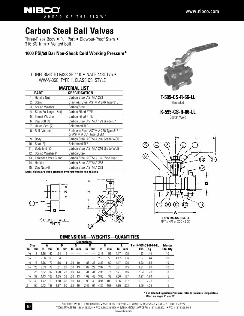
�� For detailed Operating Pressure, refer to Pressure TemperatureChart on pages 71 and 72.
NIBCO INC. WORLD HEADQUARTERS • 1516 MIDDLEBURY ST. • ELKHART, IN 46516-4740 • USA • PH: 1.800.234.0227 TECH SERVICES PH: 1.888.446.4226 • FAX: 1.888.336.4226 • INTERNATIONAL OFFICE PH: +1.574.295.3221 • FAX: +1.574.295.3455
www.nibco.com
A H E A D O F T H E F L O W ™
wwwwww..nniibbccoo..ccoomm
60
Carbon Steel Ball ValvesThree-Piece Body • Full Port • Blowout-Proof Stem •316 SS Trim • Vented Ball
1000 PSI/69 Bar Non-Shock Cold Working Pressure��
CONFORMS TO MSS SP-110 • NACE MRO175 • WW-V-35C, TYPE II, CLASS CS, STYLE 1
T-595-CS-R-66-LLThreaded
K-595-CS-R-66-LLSocket Weld
MATERIAL LISTPART SPECIFICATION
1. Handle Nut Carbon Steel ASTM A 2832. Stem Stainless Steel ASTM A 276 Type 3163. Spring Washer Carbon Steel 4. Stem Packing (1 Set) Carbon Filled PTFE5. Thrust Washer Carbon Filled PTFE6. Cap Bolt (4) Carbon Steel ASTM A 193 Grade B77. Union Seal (2) Reinforced TFE8. Ball (Vented) Stainless Steel ASTM A 276 Type 316
or ASTM A 351 Type CF8M9. Body Carbon Steel ASTM A 216 Grade WCB
10. Seat (2) Reinforced TFE11. Body End (2) Carbon Steel ASTM A 216 Grade WCB12. Spring Washer (4) Carbon Steel13. Threaded Pack Gland Carbon Steel ASTM A 108 Type 104514. Handle Carbon Steel ASTM A 28315. Cap Nut (4) Carbon Steel ASTM A 283
NOTE: Valves are static grounded by thrust washer and packing.
DIMENSIONS—WEIGHTS—QUANTITIESDimensions
Size A D G K H L T or K-595-CS-R-66-LL MasterIn. mm. In. mm. In. mm. In. mm. In. mm. In. mm. In. mm. Lbs. Kg. Ctn. Qty.¹⁄₄ 8 2.36 60 .34 9 — — — — 2.18 55 4.17 106 .97 .44 10³⁄₈ 10 2.36 60 .34 9 — — — — 2.18 55 4.17 106 .97 .44 10¹⁄₂ 15 2.76 70 .56 14 .38 10 .86 22 2.38 60 4.17 106 1.23 .56 10³⁄₄ 20 3.03 77 .81 21 .50 13 1.07 27 2.87 73 5.71 145 1.91 .87 10
1 25 3.62 92 1.00 25 .50 13 1.34 34 2.95 75 5.71 145 2.93 1.33 81 ¹⁄₄ 32 4.13 105 1.25 32 .50 13 1.69 43 3.66 93 7.36 187 4.27 1.94 51 ¹⁄₂ 40 4.72 110 1.50 38 .50 13 1.93 49 3.94 100 7.36 187 6.01 2.73 52 50 5.43 138 1.97 50 .62 16 2.42 61 4.25 108 7.95 202 9.50 4.32 5
T or K 595-CS-R-66-LLNPT x NPT or SOC x SOC
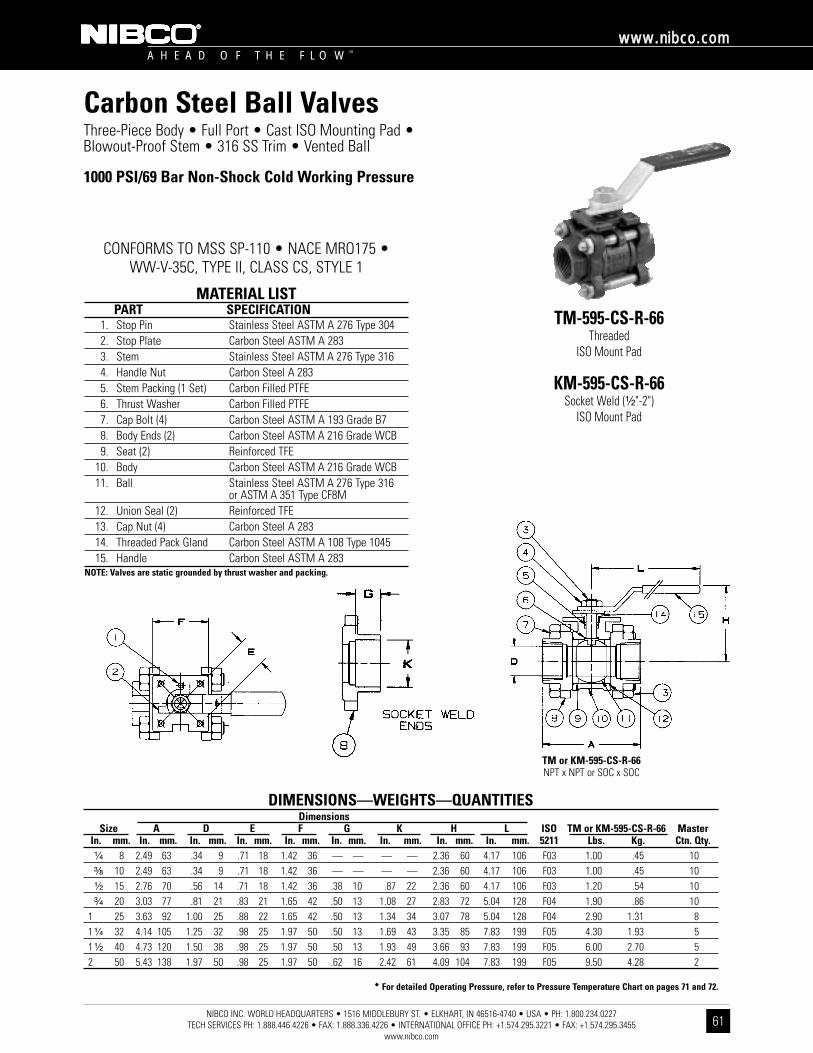
�� For detailed Operating Pressure, refer to Pressure Temperature Chart on pages 71 and 72.
DIMENSIONS—WEIGHTS—QUANTITIESDimensions
Size A D E F G K H L ISO TM or KM-595-CS-R-66 MasterIn. mm. In. mm. In. mm. In. mm. In. mm. In. mm. In. mm. In. mm. In. mm. 5211 Lbs. Kg. Ctn. Qty.¹⁄₄ 8 2.49 63 .34 9 .71 18 1.42 36 — — — — 2.36 60 4.17 106 F03 1.00 .45 10³⁄₈ 10 2.49 63 .34 9 .71 18 1.42 36 — — — — 2.36 60 4.17 106 F03 1.00 .45 10¹⁄₂ 15 2.76 70 .56 14 .71 18 1.42 36 .38 10 .87 22 2.36 60 4.17 106 F03 1.20 .54 10³⁄₄ 20 3.03 77 .81 21 .83 21 1.65 42 .50 13 1.08 27 2.83 72 5.04 128 F04 1.90 .86 10
1 25 3.63 92 1.00 25 .88 22 1.65 42 .50 13 1.34 34 3.07 78 5.04 128 F04 2.90 1.31 81 ¹⁄₄ 32 4.14 105 1.25 32 .98 25 1.97 50 .50 13 1.69 43 3.35 85 7.83 199 F05 4.30 1.93 51 ¹⁄₂ 40 4.73 120 1.50 38 .98 25 1.97 50 .50 13 1.93 49 3.66 93 7.83 199 F05 6.00 2.70 52 50 5.43 138 1.97 50 .98 25 1.97 50 .62 16 2.42 61 4.09 104 7.83 199 F05 9.50 4.28 2
NIBCO INC. WORLD HEADQUARTERS • 1516 MIDDLEBURY ST. • ELKHART, IN 46516-4740 • USA • PH: 1.800.234.0227 TECH SERVICES PH: 1.888.446.4226 • FAX: 1.888.336.4226 • INTERNATIONAL OFFICE PH: +1.574.295.3221 • FAX: +1.574.295.3455
www.nibco.com
A H E A D O F T H E F L O W ™
wwwwww..nniibbccoo..ccoomm
61
Carbon Steel Ball ValvesThree-Piece Body • Full Port • Cast ISO Mounting Pad •Blowout-Proof Stem • 316 SS Trim • Vented Ball
1000 PSI/69 Bar Non-Shock Cold Working Pressure
CONFORMS TO MSS SP-110 • NACE MRO175 • WW-V-35C, TYPE II, CLASS CS, STYLE 1
TM-595-CS-R-66Threaded
ISO Mount Pad
KM-595-CS-R-66Socket Weld (¹⁄₂"-2")
ISO Mount Pad
MATERIAL LISTPART SPECIFICATION
1. Stop Pin Stainless Steel ASTM A 276 Type 3042. Stop Plate Carbon Steel ASTM A 2833. Stem Stainless Steel ASTM A 276 Type 3164. Handle Nut Carbon Steel A 2835. Stem Packing (1 Set) Carbon Filled PTFE6. Thrust Washer Carbon Filled PTFE7. Cap Bolt (4) Carbon Steel ASTM A 193 Grade B78. Body Ends (2) Carbon Steel ASTM A 216 Grade WCB9. Seat (2) Reinforced TFE
10. Body Carbon Steel ASTM A 216 Grade WCB11. Ball Stainless Steel ASTM A 276 Type 316
or ASTM A 351 Type CF8M12. Union Seal (2) Reinforced TFE13. Cap Nut (4) Carbon Steel A 28314. Threaded Pack Gland Carbon Steel ASTM A 108 Type 104515. Handle Carbon Steel ASTM A 283
NOTE: Valves are static grounded by thrust washer and packing.
TM or KM-595-CS-R-66NPT x NPT or SOC x SOC
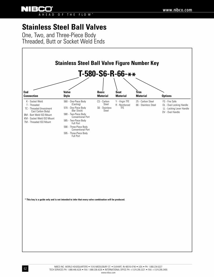
NIBCO INC. WORLD HEADQUARTERS • 1516 MIDDLEBURY ST. • ELKHART, IN 46516-4740 • USA • PH: 1.800.234.0227 TECH SERVICES PH: 1.888.446.4226 • FAX: 1.888.336.4226 • INTERNATIONAL OFFICE PH: +1.574.295.3221 • FAX: +1.574.295.3455
www.nibco.com
A H E A D O F T H E F L O W ™
wwwwww..nniibbccoo..ccoomm
62
Stainless Steel Ball ValvesOne, Two, and Three-Piece BodyThreaded, Butt or Socket Weld Ends
Stainless Steel Ball Valve Figure Number Key
T-580-S6-R-66-**
K - Socket WeldT - Threaded
TC - Threaded (Investment Cast Carbon Body)
BM - Butt Weld ISO MountKM - Socket Weld ISO MountTM - Threaded ISO Mount
560 - One-Piece Body (Casting)
570 - One-Piece Body (Bar Stock)
580 - Two-Piece BodyConventional Port
585 - Two-Piece Body Full Port
590 - Three-Piece Body Conventional Port
595 - Three-Piece Body Full Port
CS - Carbon Steel
S6 - Stainless Steel
Y - Virgin TFER - Reinforced
TFE
25 - Carbon Steel66 - Stainless Steel
FS - Fire SafeOL - Oval Locking HandleLL - Locking Lever Handle
OV - Oval Handle
* This key is a guide only and is not intended to infer that every valve combination will be produced.
End Connection
ValveStyle
BasicMaterial
SeatMaterial
TrimMaterial Options
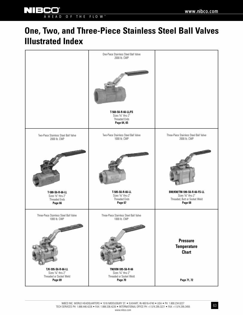
NIBCO INC. WORLD HEADQUARTERS • 1516 MIDDLEBURY ST. • ELKHART, IN 46516-4740 • USA • PH: 1.800.234.0227 TECH SERVICES PH: 1.888.446.4226 • FAX: 1.888.336.4226 • INTERNATIONAL OFFICE PH: +1.574.295.3221 • FAX: +1.574.295.3455
www.nibco.com
A H E A D O F T H E F L O W ™
wwwwww..nniibbccoo..ccoomm
63
One, Two, and Three-Piece Stainless Steel Ball ValvesIllustrated Index
One-Piece Stainless Steel Ball Valve2000 lb. CWP
Three-Piece Stainless Steel Ball Valve1000 lb. CWP
T/K-595-S6-R-66-LLSizes ¹⁄₄" thru 2"
Threaded or Socket WeldPage 69
Three-Piece Stainless Steel Ball Valve1000 lb. CWP
TM/KM-595-S6-R-66Sizes ¹⁄₄" thru 2"
Threaded or Socket WeldPage 70
Pressure Temperature
Chart
Page 71, 72
Two-Piece Stainless Steel Ball Valve1000 lb. CWP
T-585-S6-R-66-LLSizes ¹⁄₂" thru 2"Threaded Ends
Page 67
Three-Piece Stainless Steel Ball Valve2000 lb. CWP
BM/KM/TM-590-S6-R-66-FS-LLSizes ¹⁄₂" thru 2"
Threaded, Butt or Socket WeldPage 68
T-560-S6-R-66-LL/FSSizes ¹⁄₄" thru 2"Threaded EndsPage 64, 65
Two-Piece Stainless Steel Ball Valve2000 lb. CWP
T-580-S6-R-66-LLSizes ¹⁄₂" thru 2"Threaded Ends
Page 66
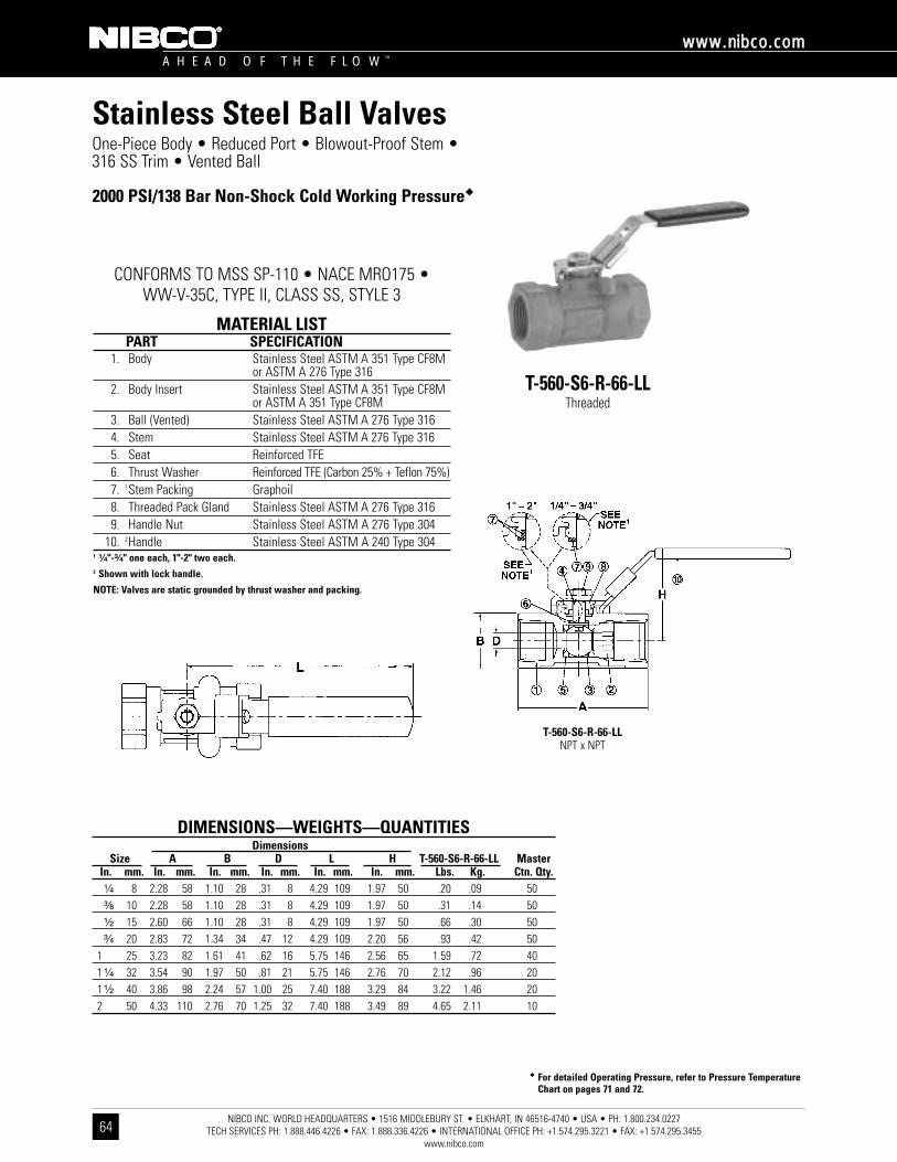
�� For detailed Operating Pressure, refer to Pressure TemperatureChart on pages 71 and 72.
NIBCO INC. WORLD HEADQUARTERS • 1516 MIDDLEBURY ST. • ELKHART, IN 46516-4740 • USA • PH: 1.800.234.0227 TECH SERVICES PH: 1.888.446.4226 • FAX: 1.888.336.4226 • INTERNATIONAL OFFICE PH: +1.574.295.3221 • FAX: +1.574.295.3455
www.nibco.com
A H E A D O F T H E F L O W ™
wwwwww..nniibbccoo..ccoomm
64
Stainless Steel Ball ValvesOne-Piece Body • Reduced Port • Blowout-Proof Stem •316 SS Trim • Vented Ball
2000 PSI/138 Bar Non-Shock Cold Working Pressure��
CONFORMS TO MSS SP-110 • NACE MRO175 • WW-V-35C, TYPE II, CLASS SS, STYLE 3
T-560-S6-R-66-LLThreaded
MATERIAL LISTPART SPECIFICATION
1. Body Stainless Steel ASTM A 351 Type CF8M or ASTM A 276 Type 316
2. Body Insert Stainless Steel ASTM A 351 Type CF8M or ASTM A 351 Type CF8M
3. Ball (Vented) Stainless Steel ASTM A 276 Type 3164. Stem Stainless Steel ASTM A 276 Type 3165. Seat Reinforced TFE6. Thrust Washer Reinforced TFE (Carbon 25% + Teflon 75%)7. 1Stem Packing Graphoil8. Threaded Pack Gland Stainless Steel ASTM A 276 Type 3169. Handle Nut Stainless Steel ASTM A 276 Type 304
10. 2Handle Stainless Steel ASTM A 240 Type 3041 ¹⁄₄"-³⁄₄" one each, 1"-2" two each.2 Shown with lock handle.
NOTE: Valves are static grounded by thrust washer and packing.
T-560-S6-R-66-LLNPT x NPT
DIMENSIONS—WEIGHTS—QUANTITIESDimensions
Size A B D L H T-560-S6-R-66-LL MasterIn. mm. In. mm. In. mm. In. mm. In. mm. In. mm. Lbs. Kg. Ctn. Qty.¹⁄₄ 8 2.28 58 1.10 28 .31 8 4.29 109 1.97 50 .20 .09 50³⁄₈ 10 2.28 58 1.10 28 .31 8 4.29 109 1.97 50 .31 .14 50¹⁄₂ 15 2.60 66 1.10 28 .31 8 4.29 109 1.97 50 .66 .30 50³⁄₄ 20 2.83 72 1.34 34 .47 12 4.29 109 2.20 56 .93 .42 50
1 25 3.23 82 1.61 41 .62 16 5.75 146 2.56 65 1.59 .72 401 ¹⁄₄ 32 3.54 90 1.97 50 .81 21 5.75 146 2.76 70 2.12 .96 201 ¹⁄₂ 40 3.86 98 2.24 57 1.00 25 7.40 188 3.29 84 3.22 1.46 202 50 4.33 110 2.76 70 1.25 32 7.40 188 3.49 89 4.65 2.11 10
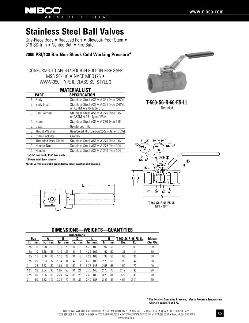
�� For detailed Operating Pressure, refer to Pressure TemperatureChart on pages 71 and 72.
NIBCO INC. WORLD HEADQUARTERS • 1516 MIDDLEBURY ST. • ELKHART, IN 46516-4740 • USA • PH: 1.800.234.0227 TECH SERVICES PH: 1.888.446.4226 • FAX: 1.888.336.4226 • INTERNATIONAL OFFICE PH: +1.574.295.3221 • FAX: +1.574.295.3455
www.nibco.com
A H E A D O F T H E F L O W ™
wwwwww..nniibbccoo..ccoomm
65
One-Piece Body • Reduced Port • Blowout-Proof Stem •316 SS Trim • Vented Ball • Fire Safe
2000 PSI/138 Bar Non-Shock Cold Working Pressure��
CONFORMS TO API-607 FOURTH EDITION FIRE SAFEMSS SP-110 • NACE MRO175 •
WW-V-35C, TYPE II, CLASS SS, STYLE 3
T-560-S6-R-66-FS-LLThreaded
MATERIAL LISTPART SPECIFICATION
1. Body Stainless Steel ASTM A 351 Type CF8M2. Body Insert Stainless Steel ASTM A 351 Type CF8M
or ASTM A 276 Type 3163. Ball (Vented) Stainless Steel ASTM A 276 Type 316
or ASTM A 351 Type CF8M4. Stem Stainless Steel ASTM A 276 Type 3165. Seat Reinforced TFE6. Thrust Washer Reinforced TFE (Carbon 25% + Teflon 75%)7. 1Stem Packing Graphoil8. Threaded Pack Gland Stainless Steel ASTM A 276 Type 3169. Handle Nut Stainless Steel ASTM A 276 Type 304
10. 2Handle Stainless Steel ASTM A 240 Type 3041 ¹⁄₄"-³⁄₄" one each, 1"-2" two each.2 Shown with lock handle.
NOTE: Valves are static grounded by thrust washer and packing.
T-560-S6-R-66-FS-LLNPT x NPT
DIMENSIONS—WEIGHTS—QUANTITIESDimensions
Size A B D L H T-560-S6-R-66-FS-LL MasterIn. mm. In. mm. In. mm. In. mm. In. mm. In. mm. Lbs. Kg. Ctn. Qty.¹⁄₄ 8 2.28 58 1.10 28 .31 8 4.29 109 1.97 50 .20 .09 50³⁄₈ 10 2.28 58 1.10 28 .31 8 4.29 109 1.97 50 .31 .14 50¹⁄₂ 15 2.60 66 1.10 28 .31 8 4.29 109 1.97 50 .66 .30 50³⁄₄ 20 2.83 72 1.34 34 .47 12 4.29 109 2.20 56 .93 .42 50
1 25 3.23 82 1.61 41 .62 16 5.75 146 2.56 65 1.59 .72 401 ¹⁄₄ 32 3.54 90 1.97 50 .81 21 5.75 146 2.76 70 2.12 .96 201 ¹⁄₂ 40 3.86 98 2.24 57 1.00 25 7.40 188 3.29 84 3.22 1.46 202 50 4.33 110 2.76 70 1.25 32 7.40 188 3.49 89 4.65 2.11 10
Stainless Steel Ball Valves

�� For detailed Operating Pressure, refer to Pressure TemperatureChart on pages 71 and 72.
NIBCO INC. WORLD HEADQUARTERS • 1516 MIDDLEBURY ST. • ELKHART, IN 46516-4740 • USA • PH: 1.800.234.0227 TECH SERVICES PH: 1.888.446.4226 • FAX: 1.888.336.4226 • INTERNATIONAL OFFICE PH: +1.574.295.3221 • FAX: +1.574.295.3455
www.nibco.com
A H E A D O F T H E F L O W ™
wwwwww..nniibbccoo..ccoomm
66
Stainless Steel Ball ValvesTwo-Piece Body • Conventional Port • Blowout-Proof Stem •316 SS Trim • Cast Mounting Pad • Vented Ball
2000 PSI/138 Bar Non-Shock Cold Working Pressure
CONFORMS TO MSS SP-110 • NACE MRO175 • WW-V-35C, TYPE II, CLASS SS, STYLE 3
T-580-S6-R-66-LLThreaded
MATERIAL LISTPART SPECIFICATION
1. Handle Nut Stainless Steel ASTM A 276 Type 3042. Stem Stainless Steel ASTM A 276 Type 3163. Spring Washer Stainless Steel 304 SS4. Threaded Pack Gland Stainless Steel ASTM A 276 Type 3165. Thrust Washer Carbon Filled PTFE6. Gasket PTFE7. Body End Piece Stainless Steel ASTM A 351 Type CF8M8. Ball (Vented) Stainless Steel ASTM A 276 Type 316
or ASTM A 351 Type CF8M9. Seat (2) Reinforced TFE
10. Body Stainless Steel ASTM A 351 Type CF8M11. Stem Packing (2) Carbon Filled PTFE12. Locking Handle Stainless Steel ASTM A 240 Type 304
NOTE: Valves are static grounded by thrust washer and packing.
T-580-S6-R-66-LLNPT x NPT
DIMENSIONS—WEIGHTS—QUANTITIESDimensions
Size A B D L H T-580-S6-R-66-LL MasterIn. mm. In. mm. In. mm. In. mm. In. mm. In. mm. Lbs. Kg. Ctn. Qty.¹⁄₄ 8 2.07 53 .83 21 .37 9 1.76 45 4.33 110 .57 .27 10³⁄₈ 10 2.07 53 .83 21 .37 9 1.76 45 4.33 110 .53 .27 10¹⁄₂ 15 2.34 59 1.06 27 .50 13 1.92 49 4.33 110 .73 .33 10³⁄₄ 20 2.80 71 1.34 34 .69 18 2.40 61 5.83 148 1.41 .64 10
1 25 3.23 82 1.61 41 .87 22 2.56 65 5.83 148 1.98 .90 101 ¹⁄₄ 32 3.57 91 1.89 48 1.00 25 2.74 70 7.76 197 2.77 1.26 51 ¹⁄₂ 40 4.04 103 2.26 57 1.25 32 2.98 76 7.76 197 4.00 1.82 52 50 4.63 118 2.76 70 1.50 38 3.17 81 7.76 197 5.70 2.59 5

�� For detailed Operating Pressure, refer to Pressure TemperatureChart on pages 71 and 72.
NIBCO INC. WORLD HEADQUARTERS • 1516 MIDDLEBURY ST. • ELKHART, IN 46516-4740 • USA • PH: 1.800.234.0227 TECH SERVICES PH: 1.888.446.4226 • FAX: 1.888.336.4226 • INTERNATIONAL OFFICE PH: +1.574.295.3221 • FAX: +1.574.295.3455
www.nibco.com
A H E A D O F T H E F L O W ™
wwwwww..nniibbccoo..ccoomm
67
Two-Piece Body • Full Port • Blowout-Proof Stem • 316 SS Trim • Cast Mounting Pad • Vented Ball
1000 PSI/69 Bar Non-Shock Cold Working Pressure
CONFORMS TO MSS SP-110 • NACE MRO175 • WW-V-35C, TYPE II, CLASS SS, STYLE 3
T-585-S6-R-66-LLThreaded
MATERIAL LISTPART SPECIFICATION
1. Handle Nut Stainless Steel ASTM A 276 Type 3042. Stem Stainless Steel ASTM A 276 Type 3163. Spring Washer Stainless Steel 3044. Threaded Pack Gland Stainless Steel ASTM A 276 Type 3165. Thrust Washer Carbon Filled PTFE6. Gasket PTFE7. Body End Piece Stainless Steel ASTM A 351 Type CF8M8. Ball (Vented) Stainless Steel ASTM A 276 Type 316
or ASTM A 351 Type CF8M9. Seat (2) Reinforced TFE
10. Body Stainless Steel ASTM A 351 Type CF8M11. Stem Packing (2) Carbon Filled PTFE12. Locking Handle Stainless Steel ASTM A 240 Type 304
NOTE: Valves are static grounded by thrust washer and packing.
T-585-S6-R-66-LLNPT x NPT
DIMENSIONS—WEIGHTS—QUANTITIESDimensions
Size A B D H L T-585-S6-R-66-LL MasterIn. mm. In. mm. In. mm. In. mm. In. mm. In. mm. Lbs. Kg. Ctn. Qty.¹⁄₄ 8 2.21 56 .83 21 .43 11 2.20 56 4.21 107 .59 .27 10³⁄₈ 10 2.21 56 .83 21 .43 11 2.20 56 4.21 107 .56 .25 10¹⁄₂ 15 2.60 66 1.02 26 .56 14 2.30 58 4.21 107 .75 .34 10³⁄₄ 20 2.99 76 1.28 33 .81 21 2.79 71 5.73 146 1.47 .67 10
1 25 3.54 90 1.56 40 1.00 25 2.96 75 5.73 146 2.21 1.00 101 ¹⁄₄ 32 3.94 100 1.97 50 1.25 35 3.56 90 7.45 189 3.42 1.55 51 ¹⁄₂ 40 4.41 112 2.20 66 1.50 38 3.84 98 7.45 189 5.20 2.36 52 50 5.00 127 2.76 69 2.00 50 4.24 108 8.08 205 7.99 3.63 5
Stainless Steel Ball Valves

�� For detailed Operating Pressure, refer to Pressure Temperature Chart on pages 71 and 72.
NIBCO INC. WORLD HEADQUARTERS • 1516 MIDDLEBURY ST. • ELKHART, IN 46516-4740 • USA • PH: 1.800.234.0227 TECH SERVICES PH: 1.888.446.4226 • FAX: 1.888.336.4226 • INTERNATIONAL OFFICE PH: +1.574.295.3221 • FAX: +1.574.295.3455
www.nibco.com
DIMENSIONS—WEIGHTS—QUANTITIESDimensions
H J K Socket ButtG Socket Socket Butt Threaded Weld Weld
Size A B C D E F Thread Flange Weld Weld Weld Weight Weight WeightIn. mm. In. mm. In. mm. In. mm. In. mm. In. mm. In. mm. Tap Type In. mm. In mm. In. mm. Lbs. Kg. Lbs. Kg. Lbs. Kg.¹⁄₂ 15 2.72 69 2.47 63 4.07 103 .43 11 .12 3 1.00 25 M5 F03 .86 22 .38 10 .84 21 1.80 .82 1.70 .78 1.60 .73³⁄₄ 20 2.94 75 2.70 69 4.07 103 .57 14 .12 3 1.00 25 M5 F03 1.08 27 .50 13 1.05 27 2.40 1.09 2.30 1.05 2.20 1.00
1 25 3.50 89 3.19 81 4.92 125 .81 21 .18 5 1.17 30 M5 F04 1.34 34 .50 13 1.32 34 3.80 1.73 3.60 1.64 3.50 1.591 ¹⁄₄ 32 3.90 99 3.64 92 5.91 150 .98 25 .20 5 1.17 30 M5 F04 1.69 43 .50 13 1.66 42 5.90 2.68 5.70 2.59 5.60 2.551 ¹⁄₂ 40 4.42 112 3.88 99 7.68 195 1.25 32 .23 8 1.39 35 M6 F05 1.93 49 .50 13 1.90 48 7.60 3.45 7.40 3.36 7.30 1.612 50 5.04 128 4.09 104 7.68 195 1.50 38 .23 8 1.39 35 M6 F05 2.42 61 .62 16 2.38 60 10.50 4.77 10.30 4.68 10.20 4.64
A H E A D O F T H E F L O W ™
wwwwww..nniibbccoo..ccoomm
68
Stainless Steel Ball ValvesThree-Piece Body • Threaded, Butt or Socket Weld Ends • Blowout-Proof Stem • Conventional Port •Enclosed Bolt Design • PTFE Seats • SS Trim • Cast ISO Mounting Pad • Vented Ball
2000 PSI/138 Bar Non-Shock Cold Working Pressure��
TM-590-S6-R-66-FS-LLThreaded
ISO Mount Pad
KM-590-S6-R-66-FS-LLSocket Weld
ISO Mount Pad
BM-590-S6-R-66-FS-LLButt Weld
ISO Mount Pad
MATERIAL LISTPART SPECIFICATION
1. Stem Stainless Steel ASTM A 276 Type 3162. Handle Nut Stainless Steel ASTM A 276 Type 3043. Flat Washer Stainless Steel ASTM A 240 Type 3044. Locking Handle Stainless Steel ASTM A 240 Type 3045. Stop Plate Stainless Steel ASTM A 240 Type 3046. Pack Gland Stainless Steel ASTM A 276 Type 3167. Stem Packing Graphite8. Body End Seal Graphite9. Bolt Stainless Steel ASTM A 193 B8 Type 304
10. 1Body End Stainless Steel ASTM A 351 Type CF8M11. Body Stainless Steel ASTM A 351 Type CF8M12. Ball (Vented) Stainless Steel ASTM A 351 Type CF8M
or ASTM A 276 Type 31613. Seat Reinforced TFE 15% Glass14. Thrust Washer Reinforced TFE 15% Glass15. Static Grounding Device Stainless Steel ASTM A 276 Type 30416. Stop Pin Stainless Steel ASTM A 276 Type 304
1 Threaded Connections: CF8M, Weld Connections: CF3M.
CONFORMS TO API-607 FOURTH EDITION FIRE SAFE •MSS SP-110 • MSS SP-72 (BUTT WELD) •
API 608 ANTI-STATIC FEATURE • NACE MRO175
Note: Valves are static grounded by two ball detents that insure electro-continuity between the stem body and ball. The valve has electro-continuity across the discharge path with a resistance of not more than 10 ohms.
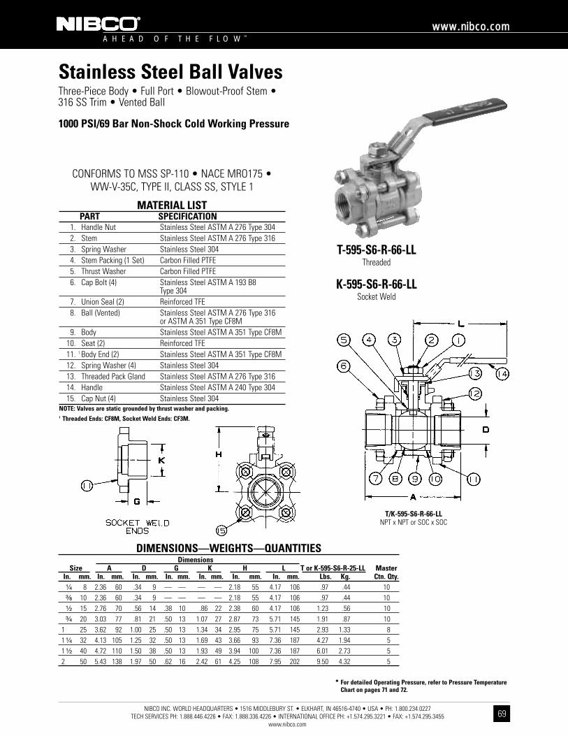
�� For detailed Operating Pressure, refer to Pressure TemperatureChart on pages 71 and 72.
NIBCO INC. WORLD HEADQUARTERS • 1516 MIDDLEBURY ST. • ELKHART, IN 46516-4740 • USA • PH: 1.800.234.0227 TECH SERVICES PH: 1.888.446.4226 • FAX: 1.888.336.4226 • INTERNATIONAL OFFICE PH: +1.574.295.3221 • FAX: +1.574.295.3455
www.nibco.com
A H E A D O F T H E F L O W ™
wwwwww..nniibbccoo..ccoomm
69
Stainless Steel Ball ValvesThree-Piece Body • Full Port • Blowout-Proof Stem •316 SS Trim • Vented Ball
1000 PSI/69 Bar Non-Shock Cold Working Pressure
CONFORMS TO MSS SP-110 • NACE MRO175 • WW-V-35C, TYPE II, CLASS SS, STYLE 1
T-595-S6-R-66-LLThreaded
K-595-S6-R-66-LLSocket Weld
MATERIAL LISTPART SPECIFICATION
1. Handle Nut Stainless Steel ASTM A 276 Type 3042. Stem Stainless Steel ASTM A 276 Type 3163. Spring Washer Stainless Steel 3044. Stem Packing (1 Set) Carbon Filled PTFE5. Thrust Washer Carbon Filled PTFE6. Cap Bolt (4) Stainless Steel ASTM A 193 B8
Type 3047. Union Seal (2) Reinforced TFE8. Ball (Vented) Stainless Steel ASTM A 276 Type 316
or ASTM A 351 Type CF8M9. Body Stainless Steel ASTM A 351 Type CF8M
10. Seat (2) Reinforced TFE11. 1 Body End (2) Stainless Steel ASTM A 351 Type CF8M12. Spring Washer (4) Stainless Steel 30413. Threaded Pack Gland Stainless Steel ASTM A 276 Type 31614. Handle Stainless Steel ASTM A 240 Type 30415. Cap Nut (4) Stainless Steel 304
NOTE: Valves are static grounded by thrust washer and packing.1 Threaded Ends: CF8M, Socket Weld Ends: CF3M.
T/K-595-S6-R-66-LLNPT x NPT or SOC x SOC
DIMENSIONS—WEIGHTS—QUANTITIESDimensions
Size A D G K H L T or K-595-S6-R-25-LL MasterIn. mm. In. mm. In. mm. In. mm. In. mm. In. mm. In. mm. Lbs. Kg. Ctn. Qty.¹⁄₄ 8 2.36 60 .34 9 — — — — 2.18 55 4.17 106 .97 .44 10³⁄₈ 10 2.36 60 .34 9 — — — — 2.18 55 4.17 106 .97 .44 10¹⁄₂ 15 2.76 70 .56 14 .38 10 .86 22 2.38 60 4.17 106 1.23 .56 10³⁄₄ 20 3.03 77 .81 21 .50 13 1.07 27 2.87 73 5.71 145 1.91 .87 10
1 25 3.62 92 1.00 25 .50 13 1.34 34 2.95 75 5.71 145 2.93 1.33 81 ¹⁄₄ 32 4.13 105 1.25 32 .50 13 1.69 43 3.66 93 7.36 187 4.27 1.94 51 ¹⁄₂ 40 4.72 110 1.50 38 .50 13 1.93 49 3.94 100 7.36 187 6.01 2.73 52 50 5.43 138 1.97 50 .62 16 2.42 61 4.25 108 7.95 202 9.50 4.32 5

�� For detailed Operating Pressure, refer to Pressure Temperature Chart on pages 71 and 72.
DIMENSIONS—WEIGHTS—QUANTITIESDimensions
Size A D E F G K H L ISO TM or KM-595-S6-R-66 MasterIn. mm. In. mm. In. mm. In. mm. In. mm. In. mm. In. mm. In. mm. In. mm. 5211 Lbs. Kg. Ctn. Qty.¹⁄₄ 8 2.49 63 .34 9 .71 18 1.42 36 — — — — 2.36 60 4.17 106 F03 1.00 .45 10³⁄₈ 10 2.49 63 .34 9 .71 18 1.42 36 — — — — 2.36 60 4.17 106 F03 1.00 .45 10¹⁄₂ 15 2.76 70 .56 14 .71 18 1.42 36 .38 10 .87 22 2.36 60 4.17 106 F03 1.20 .54 10³⁄₄ 20 3.03 77 .81 21 .83 21 1.65 42 .50 13 1.08 27 2.83 72 5.04 128 F04 1.90 .86 10
1 25 3.63 92 1.00 25 .88 22 1.65 42 .50 13 1.34 34 3.07 78 5.04 128 F04 2.90 1.31 81 ¹⁄₄ 32 4.14 105 1.25 32 .98 25 1.97 50 .50 13 1.69 43 3.35 85 7.83 199 F05 4.30 1.93 51 ¹⁄₂ 40 4.73 120 1.50 38 .98 25 1.97 50 .50 13 1.93 49 3.66 93 7.83 199 F05 6.00 2.70 52 50 5.43 138 1.97 50 .98 25 1.97 50 .62 16 2.42 61 4.09 104 7.83 199 F05 9.50 4.28 2
NIBCO INC. WORLD HEADQUARTERS • 1516 MIDDLEBURY ST. • ELKHART, IN 46516-4740 • USA • PH: 1.800.234.0227 TECH SERVICES PH: 1.888.446.4226 • FAX: 1.888.336.4226 • INTERNATIONAL OFFICE PH: +1.574.295.3221 • FAX: +1.574.295.3455
www.nibco.com
A H E A D O F T H E F L O W ™
wwwwww..nniibbccoo..ccoomm
70
Stainless Steel Ball ValvesThree-Piece Body • Full Port • Cast ISO Mounting Pad •Blowout-Proof Stem • 316 SS Trim • Vented Ball
1000 PSI/69 Bar Non-Shock Cold Working Pressure
CONFORMS TO MSS SP-110 • NACE MRO175 • WW-V-35C, TYPE II, CLASS SS, STYLE 1
TM-595-S6-R-66Threaded
ISO Mount
KM-595-S6-R-66Socket Weld (¹⁄₂"-2")
ISO Mount
MATERIAL LISTPART SPECIFICATION
1. Stop Pin Stainless Steel ASTM A 276 Type 304 2. Stop Plate Stainless Steel ASTM A 240 Type 3043. Stem Stainless Steel ASTM A 276 Type 3164. Handle Nut Stainless Steel 304 5. Stem Packing (1 Set) Carbon Filled PTFE6. Thrust Washer Carbon Filled PTFE7. Cap Bolt Stainless Steel ASTM A 193 B8 Type 3048. 1 Body End (2) Stainless Steel ASTM A 351 Type CF8M9. Seat (2) Reinforced TFE
10. Body Stainless Steel ASTM A 351 Type CF8M11. Ball (Vented) Stainless Steel ASTM A 351 Type CF8M
or ASTM A 276 Type 31612. Union Seal (2) Reinforced TFE13. Cap Nut (4) Stainless Steel 304 14. Threaded Pack Gland Stainless Steel ASTM A 276 Type 31615. Handle Stainless Steel ASTM A 240 Type 304
NOTE: Valves are static grounded by thrust washer and packing.1 Threaded Ends: CF8M, Socket Weld Ends: CF3M.
TM/KM-595-S6-R-66NPT x NPT or SOC x SOC
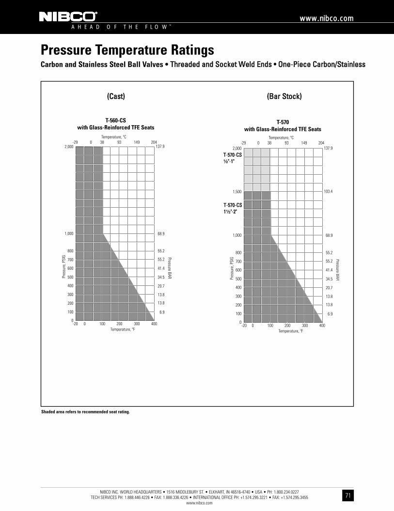
NIBCO INC. WORLD HEADQUARTERS • 1516 MIDDLEBURY ST. • ELKHART, IN 46516-4740 • USA • PH: 1.800.234.0227 TECH SERVICES PH: 1.888.446.4226 • FAX: 1.888.336.4226 • INTERNATIONAL OFFICE PH: +1.574.295.3221 • FAX: +1.574.295.3455
www.nibco.com
A H E A D O F T H E F L O W ™
wwwwww..nniibbccoo..ccoomm
71
Pressure Temperature RatingsCarbon and Stainless Steel Ball Valves • TThhrreeaaddeedd aanndd SSoocckkeett WWeelldd EEnnddss •• OOnnee-PPiieeccee CCaarrbboonn//SSttaaiinnlleessss
T-560-CSwith Glass-Reinforced TFE Seats
T-570with Glass-Reinforced TFE Seats
TT-557700-CCSS¹⁄₂""-11""
TT-557700-CCSS11¹⁄₂""-22""
((CCaasstt)) ((BBaarr SSttoocckk))
Shaded area refers to recommended seat rating.

NIBCO INC. WORLD HEADQUARTERS • 1516 MIDDLEBURY ST. • ELKHART, IN 46516-4740 • USA • PH: 1.800.234.0227 TECH SERVICES PH: 1.888.446.4226 • FAX: 1.888.336.4226 • INTERNATIONAL OFFICE PH: +1.574.295.3221 • FAX: +1.574.295.3455
www.nibco.com
A H E A D O F T H E F L O W ™
wwwwww..nniibbccoo..ccoomm
72
Pressure/Temperature RatingsCarbon and Stainless Steel Ball Valves • TThhrreeaaddeedd,, SSoocckkeett,, aanndd BBuutttt WWeelldd EEnnddssTTwwoo aanndd TThhrreeee-PPiieeccee CCaarrbboonn//SSttaaiinnlleessss
T-580-CS and S6with Glass-Reinforced TFE Seats
T/K/TM/KM-595-CS and S6 Ball Valveswith Glass-Filled PTFE Seats
TT-558800-CCSS aanndd SS66¹⁄₂""-11""
TT-558800-CCSS aanndd SS6611¹⁄₄""-22""
Shaded area refers to recommended seat rating.
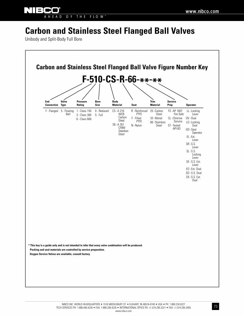
NIBCO INC. WORLD HEADQUARTERS • 1516 MIDDLEBURY ST. • ELKHART, IN 46516-4740 • USA • PH: 1.800.234.0227 TECH SERVICES PH: 1.888.446.4226 • FAX: 1.888.336.4226 • INTERNATIONAL OFFICE PH: +1.574.295.3221 • FAX: +1.574.295.3455
www.nibco.com
A H E A D O F T H E F L O W ™
wwwwww..nniibbccoo..ccoomm
73
Carbon and Stainless Steel Flanged Ball ValvesUnibody and Split-Body Full Bore
Carbon and Stainless Steel Flanged Ball Valve Figure Number Key
F-510-CS-R-66-**-**
F - Flanged
* This key is a guide only and is not intended to infer that every valve combination will be produced.
Packing and seal materials are controlled by service preparation.
Oxygen Service Valves are available, consult factory.
End Connection
ValveType
PressureRating
BoreSize
BodyMaterial Seat
TrimMaterial
ServicePrep Operator
5 - FloatingBall
1 - Class 1503 - Class 3006 - Class 600
0 - Reduced5 - Full
R - ReinforcedPTFE
F - Filled PTFE
N - Nylon
CS -A 216 WCB Carbon Steel
S6 -A 351CF8MStainlessSteel
25 -CarbonSteel
33 -Monel66 -Stainless
Steel
FS -AP 1607Fire Safe
CL -ChlorineService
ST -TestedAPI 6D
LL -LockingLever
OV -OvalLO -Locking
OvalGO -Gear
OperatorEL -Ext.
LeverSR -S.S.
LeverSL -S.S.
LockingLever
SE -S.S. Ext.Lever
EO -Ext. OvalSO -S.S. OvalSX -S.S. Ext.
Oval

NIBCO INC. WORLD HEADQUARTERS • 1516 MIDDLEBURY ST. • ELKHART, IN 46516-4740 • USA • PH: 1.800.234.0227 TECH SERVICES PH: 1.888.446.4226 • FAX: 1.888.336.4226 • INTERNATIONAL OFFICE PH: +1.574.295.3221 • FAX: +1.574.295.3455
www.nibco.com
A H E A D O F T H E F L O W ™
wwwwww..nniibbccoo..ccoomm
74
One and Two-Piece Carbon Steel Flanged Ball ValvesIllustrated Index
Unibody Carbon Steel Flanged Ball ValveANSI Class 150
Split-Body Carbon Steel Flanged Ball ValveANSI Class 300
F-535-CS-F-66-FSSizes ¹⁄₂" thru 12"
FlangedPage 82
Split-Body Carbon Steel Flanged Ball ValveANSI Class 600
F-565-CS-N-25-FSSizes 1" thru 4"
FlangedPage 83
Split-Body Carbon Steel Flanged Ball ValveANSI Class 600
F-565-CS-N-66-FSSizes 1" thru 4"
FlangedPage 84
Unibody Carbon Steel Flanged Ball ValveANSI Class 300
F-530-CS-R-33-CLSizes ¹⁄₂" thru 10"
FlangedPage 80
Split-Body Carbon Steel Flanged Ball ValveANSI Class 150
F-515-CS-F-66-FSSizes ¹⁄₂" thru 12"
FlangedPage 81
F-510-CS-R-25-FSSizes ¹⁄₂" thru 12"
FlangedPage 77Page 75, 76
Unibody Carbon Steel Flanged Ball ValveANSI Class 150
F-510-CS-R-66-FSSizes ¹⁄₂" thru 12"
FlangedPage 78
Unibody Carbon Steel Flanged Ball ValveANSI Class 300
F-530-CS-R-66-FSSizes ¹⁄₂" thru 10"
FlangedPage 79
Unibody Design DetailSplit-Body Design Detail

NIBCO INC. WORLD HEADQUARTERS • 1516 MIDDLEBURY ST. • ELKHART, IN 46516-4740 • USA • PH: 1.800.234.0227 TECH SERVICES PH: 1.888.446.4226 • FAX: 1.888.336.4226 • INTERNATIONAL OFFICE PH: +1.574.295.3221 • FAX: +1.574.295.3455
www.nibco.com
A H E A D O F T H E F L O W ™
wwwwww..nniibbccoo..ccoomm
75
The Positive Solution For All Your Flow Control Applications.NIBCO flanged ball valves provide precision, performance and value for industrial flow control applications. The unibody and split-body valvesare designed and manufactured to meet or exceed ANSI, MSS and API specifications. And both styles offer these outstanding features:
• A pressure-safe stem shoulder design that protects against failure under excess pressure.• Tight, leakproof engineered seals and bi-directional operation.• Low-friction engineered seat design for consistent and predictable low-torque operation.• Pre-drilled and tapped mounting pads that allow universal mounting of actuators.• Lock-out capability in either open or closed position for added safety.• Available in a wide range of materials and sizes.
Unibody Flanged Ball Valves• A unibody design eliminates unnecessary joint faces where leakage may occur,
and features a double-sealed end plug.• Increased packing depth allows adequate V-ring packing to prevent leakage around the stem.• Large-diameter stem provides extra protection from stresses that cause failure in smaller stems.
Flanged Ball Valves
Oval Handle with Locking Device
Predrilled and Tapped
Mounting Pads
Double-SealedEnd Plug
Positive-StopEnd Piece
Low-Friction EngineeredSeat Design
Blowout-Proof Stem
UnibodyConstruction
Combination ofFlexible and
BraidedGraphite
Packing forFiresafe
Applications

NIBCO INC. WORLD HEADQUARTERS • 1516 MIDDLEBURY ST. • ELKHART, IN 46516-4740 • USA • PH: 1.800.234.0227 TECH SERVICES PH: 1.888.446.4226 • FAX: 1.888.336.4226 • INTERNATIONAL OFFICE PH: +1.574.295.3221 • FAX: +1.574.295.3455
www.nibco.com
A H E A D O F T H E F L O W ™
wwwwww..nniibbccoo..ccoomm
76
The Positive Solution For All Your Flow Control Applications.
Split-Body Full-Bore Flanged Ball Valves• Split-body design allows greater serviceability – disassembles easily for repair or replacement of internal components.• Full-bore design provides exceptional flow control.• Multiple V-ring packing, combined with live loading, maintains packing compression under high-cycle and severe service applications.
Applicable StandardsNIBCO flanged ball valves conform to ASME/ANSI B16.34, ANSI B16.5, ANSI B16.10, MSS SP 72, API 598, API 607, API 608 and MSS SP 25.Complies to API 6D relating to materials, dimensions and testing when specified.
Special Service ApplicationsFire Safe – Secondary metal-to-metal seal acts as backup if primary seal is destroyed by fire. Valves ordered for compliance with API 607will be provided with graphite packing and gaskets.Chlorine Service – Valves can be provided to meet all specifications listed by the Chlorine Institute pamphlet No. 6, including the provisionof a vented ball, a flow directional arrow, and are cleaned and bagged to prevent contamination.Oxygen Service – Valves can be provided cleaned and bagged for oxygen or other special services.NACE – For sour gas or corrosive service, valves provide standard conformance to NACE MR-01-75.
Flanged Ball Valves
Blowout-Proof Stem
Low-FrictionEngineeredSeat Design
Predrilled andTapped
Mounting Pads
Live LoadingFeature
LockingDevice
Multiple V-RingPacking
Split-BodyConstruction
Full-BoreDesign
Graded BodyBolts and Nuts

�� For detailed Operating Pressure, refer to Pressure Temperature Chart on page 91.
DimensionsSize G H I J K L M O P F-510-CS-R-25-FS
In. mm. In. mm. In. mm. In. mm. In. mm. In. mm. In. mm. In. mm. N In. mm. In. mm. Lbs. Kg.¹⁄₂ 15 6.63 168 2.84 72 3.16 80 2.56 65 .59 15 .25 6 1.68 43 .250-20 1.19 30 1.19 30 3.00 1.36³⁄₄ 20 6.63 168 3.20 81 3.58 91 2.56 65 .76 19 .25 6 1.68 43 .250-20 1.19 30 1.19 30 5.00 2.27
1 25 6.63 168 3.45 88 3.83 97 2.56 65 .93 24 .31 8 1.68 43 .250-20 1.19 30 1.19 30 6.00 2.721 ¹⁄₂ 40 9.13 232 4.75 121 5.25 133 3.31 84 1.22 31 .56 14 2.06 52 .250-20 1.46 37 1.46 37 13.00 5.912 50 9.13 232 4.88 124 5.38 137 3.31 84 1.36 35 .56 14 2.06 52 .250-20 1.46 37 1.46 37 17.00 7.733 80 16.60 422 6.16 156 — — — — 1.97 50 .68 17 3.00 76 .375-16 2.12 54 2.12 54 42.00 19.094 100 16.60 422 7.22 183 — — — — 2.16 55 .68 17 3.00 76 .375-16 2.12 54 2.12 54 64.00 29.096 150 32.80 833 10.09 256 — — — — 3.59 91 1.13 29 4.50 114 .500-13 3.18 81 3.18 81 126.00 57.278 200 — — — — — — — — 3.43 87 1.13 29 4.50 114 .500-13 3.18 81 3.18 81 198.00 90.00
10 250 — — — — — — — — 5.56 141 1.75 44 — — .625-11 7.24 184 3.66 93 296.00 134.5512 300 — — — — — — — — 5.63 143 2.00 31 — — .625-11 8.10 205 4.68 119 477.00 216.82Note: Valves are static grounded by thrust washer.
NIBCO INC. WORLD HEADQUARTERS • 1516 MIDDLEBURY ST. • ELKHART, IN 46516-4740 • USA • PH: 1.800.234.0227 TECH SERVICES PH: 1.888.446.4226 • FAX: 1.888.336.4226 • INTERNATIONAL OFFICE PH: +1.574.295.3221 • FAX: +1.574.295.3455
www.nibco.com
A H E A D O F T H E F L O W ™
wwwwww..nniibbccoo..ccoomm
77
Class 150 Carbon Steel Flanged Ball ValvesUnibody Design • Blowout-Proof Stem • CS Trim • Mounting Pad • Fire Safe • Vented Ball
285 PSI/19.7 Bar Non-Shock Cold Working Pressure��
CONFORMS TO ASME/ANSI B16.34, B16.5, MSS SP 72,API 607 FOURTH EDITION, API 608, API 598,
MSS SP 25, NACE MR0175
F-510-CS-R-25-FSCarbon x Carbon
Flanged
MATERIAL LISTPART SPECIFICATION
1. 1Body and End Piece Carbon Steel ASTM A 216 Type WCB2. 1Ball (Vented) Carbon Steel ASTM A 216 Type WCB3. Stem Carbon Steel ASTM A 1084. Seat Glass Filled Teflon5. Packing Set Graphite and Braided Graphite6. Pack Gland Stainless Steel 304 SS7. Pack Gland Nut Carbon Steel Plated8. O-Ring Fluorocarbon Encapsulated9. Gasket 304 SS/Graphite Spiral Wound
1 Cast specifications shown. Smaller sizes may be manufactured from equivalent barstock specifications.
DIMENSIONS—WEIGHTS—QUANTITIESDimensions
Size A B C D E FIn. mm. In. mm. In. mm. In. mm. In. mm. In. mm. In. mm.¹⁄₂ 15 4.25 108 2.13 54 .47 12 3.56 90 .50 13 .43 11³⁄₄ 20 4.63 118 2.31 50 .47 12 3.94 100 .75 19 .63 16
1 25 5.00 127 2.50 54 .47 12 4.31 109 1.00 25 .81 211 ¹⁄₂ 40 6.50 165 3.25 83 .56 14 5.00 127 1.50 38 1.19 302 50 7.00 178 3.00 76 .62 16 6.00 132 2.00 51 1.50 383 80 8.00 203 4.00 102 .75 19 7.50 191 3.00 76 2.38 604 100 9.00 229 4.25 108 .94 24 9.00 229 4.00 102 3.00 766 150 10.50 267 5.25 133 1.00 25 11.00 279 6.00 152 4.38 1118 200 11.50 297 5.50 140 1.13 29 13.50 343 8.00 203 5.68 144
10 250 13.00 330 6.50 165 1.19 30 16.00 406 10.00 254 7.50 19012 300 14.00 356 7.38 187 1.25 32 19.00 483 12.00 305 9.50 241
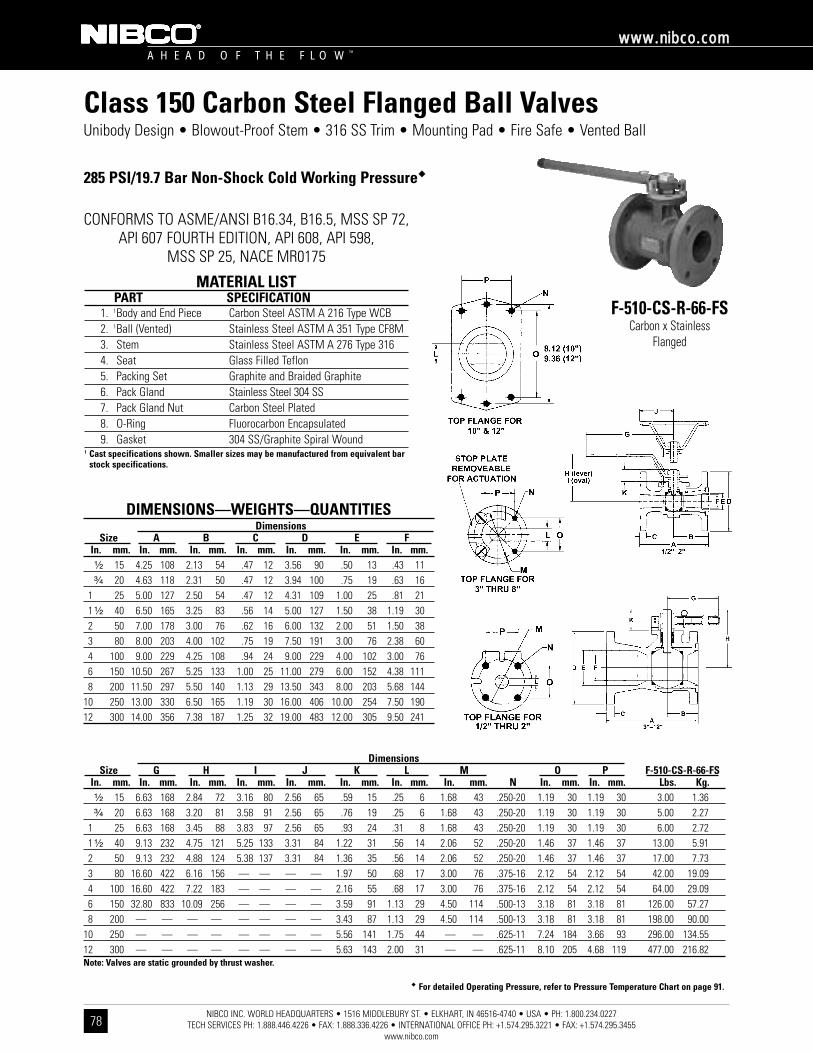
�� For detailed Operating Pressure, refer to Pressure Temperature Chart on page 91.
NIBCO INC. WORLD HEADQUARTERS • 1516 MIDDLEBURY ST. • ELKHART, IN 46516-4740 • USA • PH: 1.800.234.0227 TECH SERVICES PH: 1.888.446.4226 • FAX: 1.888.336.4226 • INTERNATIONAL OFFICE PH: +1.574.295.3221 • FAX: +1.574.295.3455
www.nibco.com
A H E A D O F T H E F L O W ™
wwwwww..nniibbccoo..ccoomm
78
Class 150 Carbon Steel Flanged Ball ValvesUnibody Design • Blowout-Proof Stem • 316 SS Trim • Mounting Pad • Fire Safe • Vented Ball
285 PSI/19.7 Bar Non-Shock Cold Working Pressure��
CONFORMS TO ASME/ANSI B16.34, B16.5, MSS SP 72,API 607 FOURTH EDITION, API 608, API 598,
MSS SP 25, NACE MR0175
F-510-CS-R-66-FSCarbon x Stainless
Flanged
MATERIAL LISTPART SPECIFICATION
1. 1Body and End Piece Carbon Steel ASTM A 216 Type WCB2. 1Ball (Vented) Stainless Steel ASTM A 351 Type CF8M3. Stem Stainless Steel ASTM A 276 Type 3164. Seat Glass Filled Teflon5. Packing Set Graphite and Braided Graphite6. Pack Gland Stainless Steel 304 SS7. Pack Gland Nut Carbon Steel Plated8. O-Ring Fluorocarbon Encapsulated9. Gasket 304 SS/Graphite Spiral Wound
1 Cast specifications shown. Smaller sizes may be manufactured from equivalent barstock specifications.
DIMENSIONS—WEIGHTS—QUANTITIESDimensions
Size A B C D E FIn. mm. In. mm. In. mm. In. mm. In. mm. In. mm. In. mm.¹⁄₂ 15 4.25 108 2.13 54 .47 12 3.56 90 .50 13 .43 11³⁄₄ 20 4.63 118 2.31 50 .47 12 3.94 100 .75 19 .63 16
1 25 5.00 127 2.50 54 .47 12 4.31 109 1.00 25 .81 211 ¹⁄₂ 40 6.50 165 3.25 83 .56 14 5.00 127 1.50 38 1.19 302 50 7.00 178 3.00 76 .62 16 6.00 132 2.00 51 1.50 383 80 8.00 203 4.00 102 .75 19 7.50 191 3.00 76 2.38 604 100 9.00 229 4.25 108 .94 24 9.00 229 4.00 102 3.00 766 150 10.50 267 5.25 133 1.00 25 11.00 279 6.00 152 4.38 1118 200 11.50 297 5.50 140 1.13 29 13.50 343 8.00 203 5.68 144
10 250 13.00 330 6.50 165 1.19 30 16.00 406 10.00 254 7.50 19012 300 14.00 356 7.38 187 1.25 32 19.00 483 12.00 305 9.50 241
DimensionsSize G H I J K L M O P F-510-CS-R-66-FS
In. mm. In. mm. In. mm. In. mm. In. mm. In. mm. In. mm. In. mm. N In. mm. In. mm. Lbs. Kg.¹⁄₂ 15 6.63 168 2.84 72 3.16 80 2.56 65 .59 15 .25 6 1.68 43 .250-20 1.19 30 1.19 30 3.00 1.36³⁄₄ 20 6.63 168 3.20 81 3.58 91 2.56 65 .76 19 .25 6 1.68 43 .250-20 1.19 30 1.19 30 5.00 2.27
1 25 6.63 168 3.45 88 3.83 97 2.56 65 .93 24 .31 8 1.68 43 .250-20 1.19 30 1.19 30 6.00 2.721 ¹⁄₂ 40 9.13 232 4.75 121 5.25 133 3.31 84 1.22 31 .56 14 2.06 52 .250-20 1.46 37 1.46 37 13.00 5.912 50 9.13 232 4.88 124 5.38 137 3.31 84 1.36 35 .56 14 2.06 52 .250-20 1.46 37 1.46 37 17.00 7.733 80 16.60 422 6.16 156 — — — — 1.97 50 .68 17 3.00 76 .375-16 2.12 54 2.12 54 42.00 19.094 100 16.60 422 7.22 183 — — — — 2.16 55 .68 17 3.00 76 .375-16 2.12 54 2.12 54 64.00 29.096 150 32.80 833 10.09 256 — — — — 3.59 91 1.13 29 4.50 114 .500-13 3.18 81 3.18 81 126.00 57.278 200 — — — — — — — — 3.43 87 1.13 29 4.50 114 .500-13 3.18 81 3.18 81 198.00 90.00
10 250 — — — — — — — — 5.56 141 1.75 44 — — .625-11 7.24 184 3.66 93 296.00 134.5512 300 — — — — — — — — 5.63 143 2.00 31 — — .625-11 8.10 205 4.68 119 477.00 216.82Note: Valves are static grounded by thrust washer.

NIBCO INC. WORLD HEADQUARTERS • 1516 MIDDLEBURY ST. • ELKHART, IN 46516-4740 • USA • PH: 1.800.234.0227 TECH SERVICES PH: 1.888.446.4226 • FAX: 1.888.336.4226 • INTERNATIONAL OFFICE PH: +1.574.295.3221 • FAX: +1.574.295.3455
www.nibco.com
A H E A D O F T H E F L O W ™
wwwwww..nniibbccoo..ccoomm
79
Class 300 Carbon Steel Flanged Ball ValvesUnibody Design • Blowout-Proof Stem • 316 SS Trim • Mounting Pad • Fire Safe • Vented Ball
740 PSI/51 Bar Non-Shock Cold Working Pressure��
CONFORMS TO ASME/ANSI B16.34, B16.5, MSS SP 72,API 607 FOURTH EDITION, API 608, API 598,
MSS SP 25, NACE MR0175
F-530-CS-R-66-FSCarbon x Stainless
Flanged
MATERIAL LISTPART SPECIFICATION
1. 1Body and End Piece Carbon Steel ASTM A 216 Type WCB2. 1Ball (Vented) Stainless Steel ASTM A 351 Type CF8M3. Stem Stainless Steel ASTM A 276 Type 3164. Seat Glass Filled Teflon5. Packing Set Graphite and Braided Graphite6. Pack Gland Stainless Steel 304 SS7. Pack Gland Nut Carbon Steel Plated8. O-Ring Fluorocarbon Encapsulated9. Gasket 304 SS/Graphite Spiral Wound
1 Cast specifications shown. Smaller sizes may be manufactured from equivalent barstock specifications.
DIMENSIONS—WEIGHTS—QUANTITIESDimensions
Size A B C D E FIn. mm. In. mm. In. mm. In. mm. In. mm. In. mm. In. mm.¹⁄₂ 15 5.50 140 2.13 54 .59 15 3.81 97 .50 13 .43 11³⁄₄ 20 6.00 152 2.31 59 .65 17 4.68 119 .75 19 .63 16
1 25 6.50 165 2.50 64 .71 18 4.94 125 1.00 25 .81 211 ¹⁄₂ 40 7.50 191 3.25 83 .81 21 6.13 156 1.50 33 1.19 302 50 8.50 216 3.00 76 .87 22 6.50 165 2.00 51 1.50 383 80 11.13 283 4.00 102 1.13 29 8.25 210 3.00 76 2.38 604 100 12.00 305 4.25 103 1.25 32 10.00 254 4.00 102 3.00 766 150 15.88 403 5.25 133 1.44 37 12.50 318 6.00 152 4.38 1118 200 16.50 419 5.50 140 1.63 41 15.00 381 8.00 203 5.68 144
10 250 18.00 457 6.50 165 1.88 48 17.50 443 10.00 254 7.50 190
DimensionsSize G H I J K L M O P F-530-CS-R-66-FS
In. mm. In. mm. In. mm. In. mm. In. mm. In. mm. In. mm. In. mm. N In. mm. In. mm. Lbs. Kg.¹⁄₂ 15 6.63 168 2.84 72 3.16 80 2.56 65 .59 15 .25 6 1.68 43 .250-20 1.19 30 1.19 30 5.00 2.27³⁄₄ 20 6.63 168 3.20 81 3.58 91 2.56 65 .76 19 .25 6 1.68 43 .250-20 1.19 30 1.19 30 8.00 3.64
1 25 6.63 168 3.45 88 3.83 97 2.56 65 .93 24 .31 8 1.68 43 .250-20 1.19 30 1.19 30 10.00 4.551 ¹⁄₂ 40 9.13 232 4.75 121 5.25 133 3.31 84 1.22 31 .56 14 2.06 52 .250-20 1.46 37 1.46 37 20.00 9.092 50 9.13 232 4.88 124 5.38 137 3.31 84 1.36 35 .56 14 2.06 52 .250-20 1.46 37 1.46 37 23.00 10.453 80 16.60 422 6.16 156 — — — — 1.97 50 .68 17 3.00 76 .375-16 2.12 54 2.12 54 54.00 24.554 100 16.60 422 7.22 183 — — — — 2.16 55 .68 17 3.00 76 .375-16 2.12 54 2.12 54 91.50 41.596 150 32.80 833 10.09 256 — — — — 3.59 91 1.13 29 4.50 114 .500-13 3.18 81 3.18 81 181.50 82.508 200 — — — — — — — — 3.43 87 1.13 29 4.50 114 .500-13 3.18 81 3.18 81 257.00 116.82
10 250 — — — — — — — — 5.56 141 1.75 44 — — .625-11 7.24 184 3.66 93 429.00 195.00Note: Valves are static grounded by thrust washer.
�� For detailed Operating Pressure, refer to Pressure Temperature Chart on page 91.

�� For detailed Operating Pressure, refer to Pressure Temperature Chart on page 91.
NIBCO INC. WORLD HEADQUARTERS • 1516 MIDDLEBURY ST. • ELKHART, IN 46516-4740 • USA • PH: 1.800.234.0227 TECH SERVICES PH: 1.888.446.4226 • FAX: 1.888.336.4226 • INTERNATIONAL OFFICE PH: +1.574.295.3221 • FAX: +1.574.295.3455
www.nibco.com
A H E A D O F T H E F L O W ™
wwwwww..nniibbccoo..ccoomm
80
Class 300 Carbon Steel Flanged Ball ValvesUnibody Design • Blowout-Proof Stem • Monel Trim • Mounting Pad • Vented Ball
740 PSI/51 Bar Non-Shock Cold Working Pressure��
CONFORMS TO ASME/ANSI B16.34, B16.5, MSS SP 72,API 608, API 598, MSS SP 25, NACE MR0175,
CHLORINE INSTITUTE PAMPHLET NO. 6
F-530-CS-R-33-CLCarbon x Monel
Flanged
MATERIAL LISTPART SPECIFICATION
1. 1Body and End Piece Carbon Steel ASTM A 216 Type WCB2. 1Ball (Vented) Monel ASTM A 494 Grade M35 13. Stem Monel B 1644. Seat Glass Filled Teflon5. Packing Set Virgin TFE6. Pack Gland Monel B 1647. Pack Gland Nut Monel8. O-Ring Fluorocarbon Encapsulated9. Gasket Monel/TFE
1 Cast specifications shown. Smaller sizes may be manufactured from equivalent barstock specifications.
DIMENSIONS—WEIGHTS—QUANTITIESDimensions
Size A B C D E FIn. mm. In. mm. In. mm. In. mm. In. mm. In. mm. In. mm.¹⁄₂ 15 5.50 140 2.13 54 .59 15 3.81 97 .50 13 .43 11³⁄₄ 20 6.00 152 2.31 59 .65 17 4.68 119 .75 19 .63 16
1 25 6.50 165 2.50 64 .71 18 4.94 125 1.00 25 .81 211 ¹⁄₂ 40 7.50 191 3.25 83 .81 21 6.13 156 1.50 33 1.19 302 50 8.50 216 3.00 76 .87 22 6.50 165 2.00 51 1.50 383 80 11.13 283 4.00 102 1.13 29 8.25 210 3.00 76 2.38 604 100 12.00 305 4.25 103 1.25 32 10.00 254 4.00 102 3.00 766 150 15.88 403 5.25 133 1.44 37 12.50 318 6.00 152 4.38 1118 200 16.50 419 5.50 140 1.63 41 15.00 381 8.00 203 5.68 144
10 250 18.00 457 6.50 165 1.88 48 17.50 443 10.00 254 7.50 190
DimensionsSize G H I J K L M O P F-530-CS-R-33-CL
In. mm. In. mm. In. mm. In. mm. In. mm. In. mm. In. mm. In. mm. N In. mm. In. mm. Lbs. Kg.¹⁄₂ 15 6.63 168 2.84 72 3.16 80 2.56 65 .59 15 .25 6 1.68 43 .250-20 1.19 30 1.19 30 5.00 2.27³⁄₄ 20 6.63 168 3.20 81 3.58 91 2.56 65 .76 19 .25 6 1.68 43 .250-20 1.19 30 1.19 30 8.00 3.64
1 25 6.63 168 3.45 88 3.83 97 2.56 65 .93 24 .31 8 1.68 43 .250-20 1.19 30 1.19 30 10.00 4.551 ¹⁄₂ 40 9.13 232 4.75 121 5.25 133 3.31 84 1.22 31 .56 14 2.06 52 .250-20 1.46 37 1.46 37 20.00 9.092 50 9.13 232 4.88 124 5.38 137 3.31 84 1.36 35 .56 14 2.06 52 .250-20 1.46 37 1.46 37 23.00 10.453 80 16.60 422 6.16 156 — — — — 1.97 50 .68 17 3.00 76 .375-16 2.12 54 2.12 54 54.00 24.554 100 16.60 422 7.22 183 — — — — 2.16 55 .68 17 3.00 76 .375-16 2.12 54 2.12 54 91.50 41.596 150 32.80 833 10.09 256 — — — — 3.59 91 1.13 29 4.50 114 .500-13 3.18 81 3.18 81 181.50 82.508 200 — — — — — — — — 3.43 87 1.13 29 4.50 114 .500-13 3.18 81 3.18 81 257.00 116.82
10 250 — — — — — — — — 5.56 141 1.75 44 — — .625-11 7.24 184 3.66 93 429.00 195.00Note: Valves are static grounded by thrust washer.
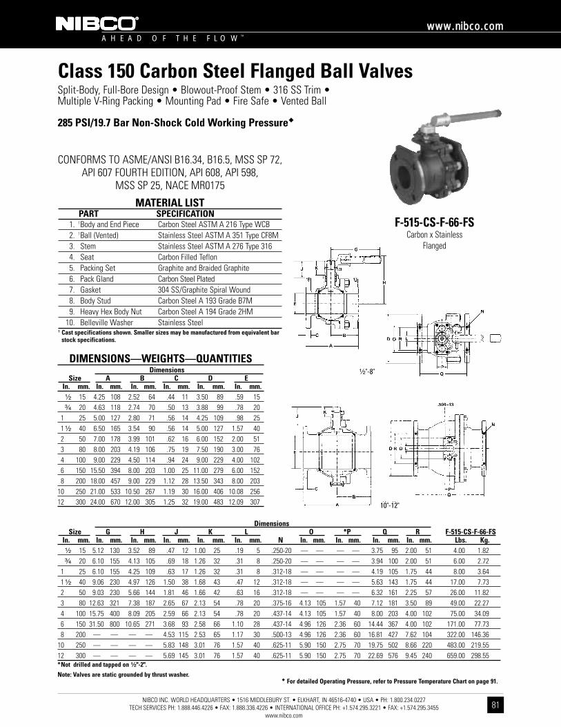
�� For detailed Operating Pressure, refer to Pressure Temperature Chart on page 91.
NIBCO INC. WORLD HEADQUARTERS • 1516 MIDDLEBURY ST. • ELKHART, IN 46516-4740 • USA • PH: 1.800.234.0227 TECH SERVICES PH: 1.888.446.4226 • FAX: 1.888.336.4226 • INTERNATIONAL OFFICE PH: +1.574.295.3221 • FAX: +1.574.295.3455
www.nibco.com
A H E A D O F T H E F L O W ™
wwwwww..nniibbccoo..ccoomm
81
Class 150 Carbon Steel Flanged Ball ValvesSplit-Body, Full-Bore Design • Blowout-Proof Stem • 316 SS Trim • Multiple V-Ring Packing • Mounting Pad • Fire Safe • Vented Ball
285 PSI/19.7 Bar Non-Shock Cold Working Pressure��
CONFORMS TO ASME/ANSI B16.34, B16.5, MSS SP 72,API 607 FOURTH EDITION, API 608, API 598,
MSS SP 25, NACE MR0175
F-515-CS-F-66-FSCarbon x Stainless
Flanged
MATERIAL LISTPART SPECIFICATION
1. 1Body and End Piece Carbon Steel ASTM A 216 Type WCB2. 1Ball (Vented) Stainless Steel ASTM A 351 Type CF8M3. Stem Stainless Steel ASTM A 276 Type 3164. Seat Carbon Filled Teflon5. Packing Set Graphite and Braided Graphite6. Pack Gland Carbon Steel Plated7. Gasket 304 SS/Graphite Spiral Wound8. Body Stud Carbon Steel A 193 Grade B7M9. Heavy Hex Body Nut Carbon Steel A 194 Grade 2HM
10. Belleville Washer Stainless Steel1 Cast specifications shown. Smaller sizes may be manufactured from equivalent bar
stock specifications.
DIMENSIONS—WEIGHTS—QUANTITIESDimensions
Size A B C D EIn. mm. In. mm. In. mm. In. mm. In. mm. In. mm.¹⁄₂ 15 4.25 108 2.52 64 .44 11 3.50 89 .59 15³⁄₄ 20 4.63 118 2.74 70 .50 13 3.88 99 .78 20
1 25 5.00 127 2.80 71 .56 14 4.25 109 .98 251 ¹⁄₂ 40 6.50 165 3.54 90 .56 14 5.00 127 1.57 402 50 7.00 178 3.99 101 .62 16 6.00 152 2.00 513 80 8.00 203 4.19 106 .75 19 7.50 190 3.00 764 100 9.00 229 4.50 114 .94 24 9.00 229 4.00 1026 150 15.50 394 8.00 203 1.00 25 11.00 279 6.00 1528 200 18.00 457 9.00 229 1.12 28 13.50 343 8.00 203
10 250 21.00 533 10.50 267 1.19 30 16.00 406 10.08 25612 300 24.00 670 12.00 305 1.25 32 19.00 483 12.09 307
DimensionsSize G H J K L O *P Q R F-515-CS-F-66-FS
In. mm. In. mm. In. mm. In. mm. In. mm. In. mm. N In. mm. In. mm. In. mm. In. mm. Lbs. Kg.¹⁄₂ 15 5.12 130 3.52 89 .47 12 1.00 25 .19 5 .250-20 — — — — 3.75 95 2.00 51 4.00 1.82³⁄₄ 20 6.10 155 4.13 105 .69 18 1.26 32 .31 8 .250-20 — — — — 3.94 100 2.00 51 6.00 2.72
1 25 6.10 155 4.25 109 .63 17 1.26 32 .31 8 .312-18 — — — — 4.19 105 1.75 44 8.00 3.641 ¹⁄₂ 40 9.06 230 4.97 126 1.50 38 1.68 43 .47 12 .312-18 — — — — 5.63 143 1.75 44 17.00 7.732 50 9.03 230 5.66 144 1.81 46 1.66 42 .63 16 .312-18 — — — — 6.32 161 2.25 57 26.00 11.823 80 12.63 321 7.38 187 2.65 67 2.13 54 .78 20 .375-16 4.13 105 1.57 40 7.12 181 3.50 89 49.00 22.274 100 15.75 400 8.09 205 2.59 66 2.13 54 .78 20 .437-14 4.13 105 1.57 40 8.00 203 4.00 102 75.00 34.096 150 31.50 800 10.65 271 3.68 93 2.58 66 1.10 28 .437-14 4.96 126 2.36 60 14.44 367 4.00 102 171.00 77.738 200 — — — — 4.53 115 2.53 65 1.17 30 .500-13 4.96 126 2.36 60 16.81 427 7.62 104 322.00 146.36
10 250 — — — — 5.83 148 3.01 76 1.57 40 .625-11 5.90 150 2.75 70 19.75 502 8.66 220 483.00 219.5512 300 — — — — 5.69 145 3.01 76 1.57 40 .625-11 5.90 150 2.75 70 22.69 576 9.45 240 659.00 298.55*Not drilled and tapped on ¹⁄₂"-2".
Note: Valves are static grounded by thrust washer.
¹⁄₂"-8"
10"-12"
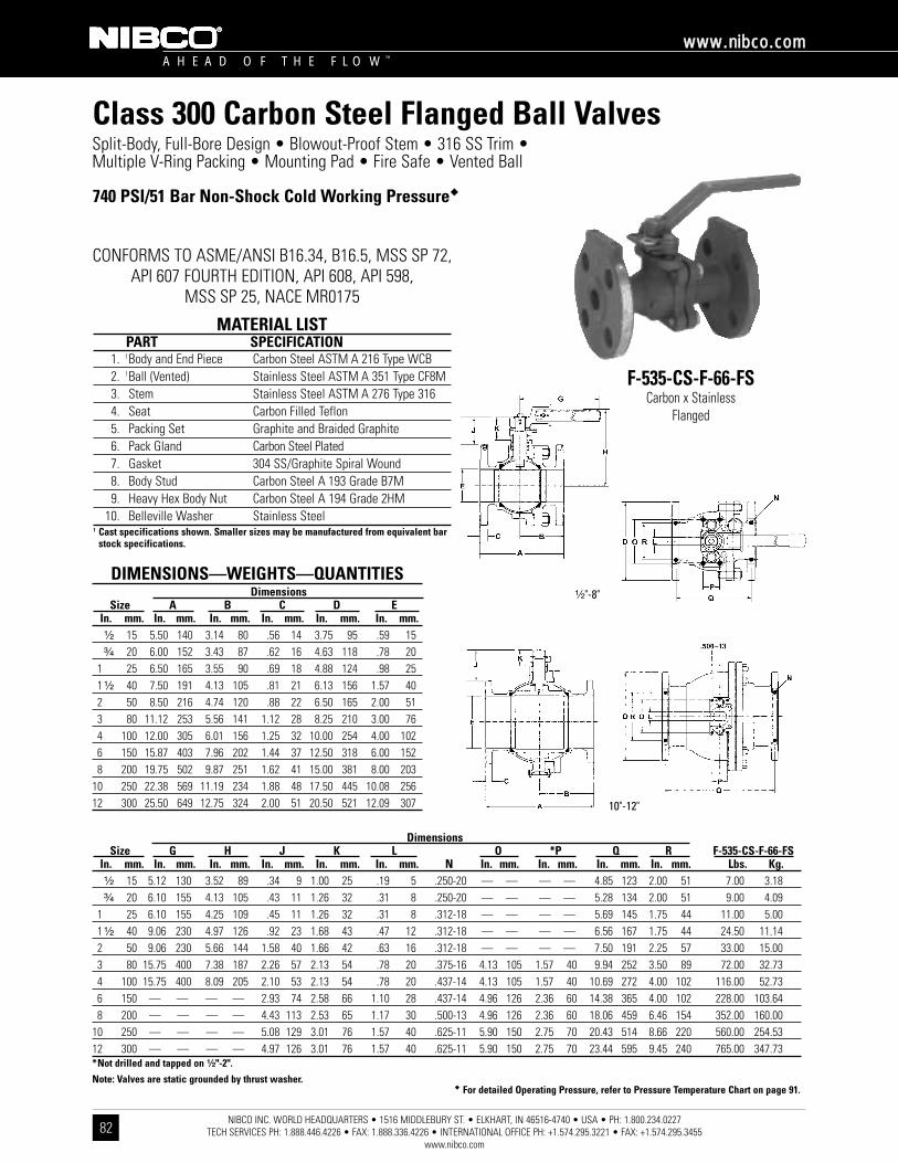
�� For detailed Operating Pressure, refer to Pressure Temperature Chart on page 91.
DimensionsSize G H J K L O *P Q R F-535-CS-F-66-FS
In. mm. In. mm. In. mm. In. mm. In. mm. In. mm. N In. mm. In. mm. In. mm. In. mm. Lbs. Kg.¹⁄₂ 15 5.12 130 3.52 89 .34 9 1.00 25 .19 5 .250-20 — — — — 4.85 123 2.00 51 7.00 3.18³⁄₄ 20 6.10 155 4.13 105 .43 11 1.26 32 .31 8 .250-20 — — — — 5.28 134 2.00 51 9.00 4.09
1 25 6.10 155 4.25 109 .45 11 1.26 32 .31 8 .312-18 — — — — 5.69 145 1.75 44 11.00 5.001 ¹⁄₂ 40 9.06 230 4.97 126 .92 23 1.68 43 .47 12 .312-18 — — — — 6.56 167 1.75 44 24.50 11.142 50 9.06 230 5.66 144 1.58 40 1.66 42 .63 16 .312-18 — — — — 7.50 191 2.25 57 33.00 15.003 80 15.75 400 7.38 187 2.26 57 2.13 54 .78 20 .375-16 4.13 105 1.57 40 9.94 252 3.50 89 72.00 32.734 100 15.75 400 8.09 205 2.10 53 2.13 54 .78 20 .437-14 4.13 105 1.57 40 10.69 272 4.00 102 116.00 52.736 150 — — — — 2.93 74 2.58 66 1.10 28 .437-14 4.96 126 2.36 60 14.38 365 4.00 102 228.00 103.648 200 — — — — 4.43 113 2.53 65 1.17 30 .500-13 4.96 126 2.36 60 18.06 459 6.46 154 352.00 160.00
10 250 — — — — 5.08 129 3.01 76 1.57 40 .625-11 5.90 150 2.75 70 20.43 514 8.66 220 560.00 254.5312 300 — — — — 4.97 126 3.01 76 1.57 40 .625-11 5.90 150 2.75 70 23.44 595 9.45 240 765.00 347.73*Not drilled and tapped on ¹⁄₂"-2".
Note: Valves are static grounded by thrust washer.
NIBCO INC. WORLD HEADQUARTERS • 1516 MIDDLEBURY ST. • ELKHART, IN 46516-4740 • USA • PH: 1.800.234.0227 TECH SERVICES PH: 1.888.446.4226 • FAX: 1.888.336.4226 • INTERNATIONAL OFFICE PH: +1.574.295.3221 • FAX: +1.574.295.3455
www.nibco.com
A H E A D O F T H E F L O W ™
wwwwww..nniibbccoo..ccoomm
82
Class 300 Carbon Steel Flanged Ball ValvesSplit-Body, Full-Bore Design • Blowout-Proof Stem • 316 SS Trim • Multiple V-Ring Packing • Mounting Pad • Fire Safe • Vented Ball
740 PSI/51 Bar Non-Shock Cold Working Pressure��
CONFORMS TO ASME/ANSI B16.34, B16.5, MSS SP 72,API 607 FOURTH EDITION, API 608, API 598,
MSS SP 25, NACE MR0175
F-535-CS-F-66-FSCarbon x Stainless
Flanged
MATERIAL LISTPART SPECIFICATION
1. 1Body and End Piece Carbon Steel ASTM A 216 Type WCB2. 1Ball (Vented) Stainless Steel ASTM A 351 Type CF8M3. Stem Stainless Steel ASTM A 276 Type 3164. Seat Carbon Filled Teflon5. Packing Set Graphite and Braided Graphite6. Pack Gland Carbon Steel Plated7. Gasket 304 SS/Graphite Spiral Wound8. Body Stud Carbon Steel A 193 Grade B7M9. Heavy Hex Body Nut Carbon Steel A 194 Grade 2HM
10. Belleville Washer Stainless Steel1 Cast specifications shown. Smaller sizes may be manufactured from equivalent bar
stock specifications.
DIMENSIONS—WEIGHTS—QUANTITIESDimensions
Size A B C D EIn. mm. In. mm. In. mm. In. mm. In. mm. In. mm.¹⁄₂ 15 5.50 140 3.14 80 .56 14 3.75 95 .59 15³⁄₄ 20 6.00 152 3.43 87 .62 16 4.63 118 .78 20
1 25 6.50 165 3.55 90 .69 18 4.88 124 .98 251 ¹⁄₂ 40 7.50 191 4.13 105 .81 21 6.13 156 1.57 402 50 8.50 216 4.74 120 .88 22 6.50 165 2.00 513 80 11.12 253 5.56 141 1.12 28 8.25 210 3.00 764 100 12.00 305 6.01 156 1.25 32 10.00 254 4.00 1026 150 15.87 403 7.96 202 1.44 37 12.50 318 6.00 1528 200 19.75 502 9.87 251 1.62 41 15.00 381 8.00 203
10 250 22.38 569 11.19 234 1.88 48 17.50 445 10.08 25612 300 25.50 649 12.75 324 2.00 51 20.50 521 12.09 307
¹⁄₂"-8"
10"-12"
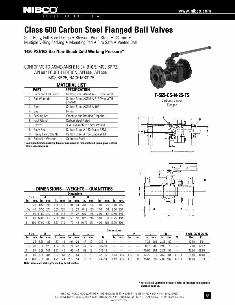
�� For detailed Operating Pressure, refer to Pressure TemperatureChart on page 91.
DimensionsSize H J K L O P Q R F-565-CS-N-25-FS
In. mm. In. mm. In. mm. In. mm. In. mm. N In. mm. In. mm. In. mm. In. mm. S Lbs. Kg.1 25 3.38 86 .57 14 1.04 26 .47 12 .312-18 — — — — 7.32 186 2.36 60 — 13.00 5.911 ¹⁄₂ 40 5.04 128 1.04 26 1.71 43 .47 12 .312-18 — — — — 8.12 206 2.99 76 — 27.00 12.272 50 5.66 144 1.57 40 1.66 42 .63 16 .312-18 — — — — 10.00 254 2.24 57 — 43.00 19.553 80 7.38 187 2.27 58 2.13 54 .78 20 .375-16 4.13 105 1.57 40 12.25 311 3.50 84 .437-14 89.50 40.684 100 8.09 205 1.72 44 2.13 54 .78 20 .437-14 4.13 105 1.57 40 15.00 331 4.00 102 .437-14 149.00 67.73
Note: Valves are static grounded by thrust washer.
NIBCO INC. WORLD HEADQUARTERS • 1516 MIDDLEBURY ST. • ELKHART, IN 46516-4740 • USA • PH: 1.800.234.0227 TECH SERVICES PH: 1.888.446.4226 • FAX: 1.888.336.4226 • INTERNATIONAL OFFICE PH: +1.574.295.3221 • FAX: +1.574.295.3455
www.nibco.com
A H E A D O F T H E F L O W ™
wwwwww..nniibbccoo..ccoomm
83
Class 600 Carbon Steel Flanged Ball ValvesSplit-Body, Full-Bore Design • Blowout-Proof Stem • CS Trim • Multiple V-Ring Packing • Mounting Pad • Fire Safe • Vented Ball
1480 PSI/102 Bar Non-Shock Cold Working Pressure��
CONFORMS TO ASME/ANSI B16.34, B16.5, MSS SP 72,API 607 FOURTH EDITION, API 608, API 598,
MSS SP 25, NACE MR0175
F-565-CS-N-25-FSCarbon x Carbon
Flanged
MATERIAL LISTPART SPECIFICATION
1. Body and End Piece Carbon Steel ASTM A 216 Type WCB2. 1Ball (Vented) Carbon Steel ASTM A 216 Type WCB
(Plated)3. Stem Carbon Steel ASTM A 1084. Seat Nylon5. Packing Set Graphite and Braided Graphite6. Pack Gland Carbon Steel Plated7. Gasket 304 SS/Graphite Spiral Wound8. Body Stud Carbon Steel A 193 Grade B7M9. Heavy Hex Body Nut Carbon Steel A 194 Grade 2HM
10. Belleville Washer Stainless Steel1 Cast specifications shown. Smaller sizes may be manufactured from equivalent bar
stock specifications.
DIMENSIONS—WEIGHTS—QUANTITIESDimensions
Size A B C D E GIn. mm. In. mm. In. mm. In. mm. In. mm. In. mm. In. mm.
1 25 8.50 216 4.68 119 .94 24 4.88 124 1.00 25 6.10 1551 ¹⁄₂ 40 9.50 241 5.09 121 1.13 29 6.12 155 1.50 38 9.06 2302 50 11.50 292 5.75 146 1.25 32 6.50 165 2.00 57 17.50 4453 80 14.00 356 7.00 168 1.50 38 8.25 210 3.00 76 15.75 4004 100 17.00 432 8.27 210 1.75 44 10.75 273 4.00 102 15.75 400

�� For detailed Operating Pressure, refer to Pressure TemperatureChart on page 91.
DimensionsSize H J K L O P Q R F-565-CS-N-66-FS
In. mm. In. mm. In. mm. In. mm. In. mm. N In. mm. In. mm. In. mm. In. mm. S Lbs. Kg.1 25 3.38 86 .57 14 1.04 26 .47 12 .312-18 — — — — 7.32 186 2.36 60 — 13.00 5.911 ¹⁄₂ 40 5.04 128 1.04 26 1.71 43 .47 12 .312-18 — — — — 8.12 206 2.99 76 — 27.00 12.272 50 5.66 144 1.57 40 1.66 42 .63 16 .312-18 — — — — 10.00 254 2.24 57 — 43.00 19.553 80 7.38 187 2.27 58 2.13 54 .78 20 .375-16 4.13 105 1.57 40 12.25 311 3.50 84 .437-14 89.50 40.684 100 8.09 205 1.72 44 2.13 54 .78 20 .437-14 4.13 105 1.57 40 15.00 331 4.00 102 .437-14 149.00 67.73
Note: Valves are static grounded by thrust washer.
NIBCO INC. WORLD HEADQUARTERS • 1516 MIDDLEBURY ST. • ELKHART, IN 46516-4740 • USA • PH: 1.800.234.0227 TECH SERVICES PH: 1.888.446.4226 • FAX: 1.888.336.4226 • INTERNATIONAL OFFICE PH: +1.574.295.3221 • FAX: +1.574.295.3455
www.nibco.com
A H E A D O F T H E F L O W ™
wwwwww..nniibbccoo..ccoomm
84
Class 600 Carbon Steel Flanged Ball ValvesSplit-Body, Full-Bore Design • Blowout-Proof Stem • 316 SS Trim • Multiple V-Ring Packing • Mounting Pad • Fire Safe • Vented Ball
1480 PSI/102 Bar Non-Shock Cold Working Pressure��
CONFORMS TO ASME/ANSI B16.34, B16.5, MSS SP 72,API 607 FOURTH EDITION, API 608, API 598,
MSS SP 25, NACE MR0175
F-565-CS-N-66-FSCarbon x Stainless
Flanged
MATERIAL LISTPART SPECIFICATION
1. Body and End Piece Carbon Steel ASTM A 216 Type WCB2. 1Ball (Vented) Stainless Steel ASTM A 351 Type CF8M3. Stem Stainless Steel ASTM A 276 Type 3164. Seat Nylon5. Packing Set Graphite and Braided Graphite6. Pack Gland Carbon Steel Plated7. Gasket 304 SS/Graphite Spiral Wound8. Body Stud Carbon Steel A 193 Grade B7M9. Heavy Hex Body Nut Carbon Steel A 194 Grade 2HM
10. Belleville Washer Stainless Steel1 Cast specifications shown. Smaller sizes may be manufactured from equivalent bar
stock specifications.
DIMENSIONS—WEIGHTS—QUANTITIESDimensions
Size A B C D E GIn. mm. In. mm. In. mm. In. mm. In. mm. In. mm. In. mm.
1 25 8.50 216 4.68 119 .94 24 4.88 124 1.00 25 6.10 1551 ¹⁄₂ 40 9.50 241 5.09 121 1.13 29 6.12 155 1.50 38 9.06 2302 50 11.50 292 5.75 146 1.25 32 6.50 165 2.00 57 17.50 4453 80 14.00 356 7.00 168 1.50 38 8.25 210 3.00 76 15.75 4004 100 17.00 432 8.27 210 1.75 44 10.75 273 4.00 102 15.75 400

NIBCO INC. WORLD HEADQUARTERS • 1516 MIDDLEBURY ST. • ELKHART, IN 46516-4740 • USA • PH: 1.800.234.0227 TECH SERVICES PH: 1.888.446.4226 • FAX: 1.888.336.4226 • INTERNATIONAL OFFICE PH: +1.574.295.3221 • FAX: +1.574.295.3455
www.nibco.com
A H E A D O F T H E F L O W ™
wwwwww..nniibbccoo..ccoomm
85
One and Two-Piece Stainless Steel Ball ValvesIllustrated Index
Unibody Stainless Steel Flanged Ball ValveANSI Class 150
Split-Body Stainless Steel Flanged Ball ValveANSI Class 600
F-565-S6-N-66-FSSizes 1" thru 4"
FlangedPage 90
Pressure Temperature
Chart
Page 91
Split-Body Stainless Steel Flanged Ball ValveANSI Class 150
F-515-S6-F-66-FSSizes ¹⁄₂" thru 12"
FlangedPage 88
Split-Body Stainless Steel Flanged Ball ValveANSI Class 300
F-535-S6-F-66-FSSizes ¹⁄₂" thru 12"
FlangedPage 89
F-510-S6-R-66-FSSizes ¹⁄₂" thru 12"
FlangedPage 86
Unibody Stainless Steel Flanged Ball ValveANSI Class 300
F-530-S6-R-66-FSSizes ¹⁄₂" thru 12"
FlangedPage 87

�� For detailed Operating Pressure, refer to Pressure Temperature Chart on page 91.
NIBCO INC. WORLD HEADQUARTERS • 1516 MIDDLEBURY ST. • ELKHART, IN 46516-4740 • USA • PH: 1.800.234.0227 TECH SERVICES PH: 1.888.446.4226 • FAX: 1.888.336.4226 • INTERNATIONAL OFFICE PH: +1.574.295.3221 • FAX: +1.574.295.3455
www.nibco.com
A H E A D O F T H E F L O W ™
wwwwww..nniibbccoo..ccoomm
86
Class 150 Stainless Steel Flanged Ball ValvesUnibody Design • Blowout-Proof Stem • 316 SS Trim • Mounting Pad • Fire Safe • Vented Ball
275 PSI/19 Bar Non-Shock Cold Working Pressure��
CONFORMS TO ASME/ANSI B16.34, B16.5, MSS SP 72,API 607 FOURTH EDITION, API 608, API 598,
MSS SP 25, NACE MR0175
F-510-S6-R-66-FSStainless x Stainless
Flanged
MATERIAL LISTPART SPECIFICATION
1. 1Body and End Piece Stainless Steel ASTM A 351 Type CF8M2. 1Ball (Vented) Stainless Steel ASTM A 351 Type CF8M3. Stem Stainless Steel ASTM A 276 Type 3164. Seat Glass Filled Teflon5. Packing Set Graphite and Braided Graphite6. Pack Gland Stainless Steel 304 SS7. Pack Gland Nut Stainless Steel8. O-Ring Fluorocarbon Encapsulated9. Gasket 304 SS/Graphite Spiral Wound
1 Cast specifications shown. Smaller sizes may be manufactured from equivalent barstock specifications.
DIMENSIONS—WEIGHTS—QUANTITIESDimensions
Size A B C D E FIn. mm. In. mm. In. mm. In. mm. In. mm. In. mm. In. mm.¹⁄₂ 15 4.25 108 2.13 54 .47 12 3.56 90 .50 13 .43 11³⁄₄ 20 4.63 118 2.31 50 .47 12 3.94 100 .75 19 .63 16
1 25 5.00 127 2.50 54 .47 12 4.31 109 1.00 25 .81 211 ¹⁄₂ 40 6.50 165 3.25 83 .56 14 5.00 127 1.50 38 1.19 302 50 7.00 178 3.00 76 .62 16 6.00 132 2.00 51 1.50 383 80 8.00 203 4.00 102 .75 19 7.50 191 3.00 76 2.38 604 100 9.00 229 4.25 108 .94 24 9.00 229 4.00 102 3.00 766 150 10.50 267 5.25 133 1.00 25 11.00 279 6.00 152 4.38 1118 200 11.50 297 5.50 140 1.13 29 13.50 343 8.00 203 5.68 144
10 250 13.00 330 6.50 165 1.19 30 16.00 406 10.00 254 7.50 19012 300 14.00 356 7.38 187 1.25 32 19.00 483 12.00 305 9.50 241
DimensionsSize G H I J K L M O P F-510-S6-R-66-FS
In. mm. In. mm. In. mm. In. mm. In. mm. In. mm. In. mm. In. mm. N In. mm. In. mm. Lbs. Kg.¹⁄₂ 15 6.63 168 2.84 72 3.16 80 2.56 65 .59 15 .25 6 1.68 43 .250-20 1.19 30 1.19 30 3.00 1.36³⁄₄ 20 6.63 168 3.20 81 3.58 91 2.56 65 .76 19 .25 6 1.68 43 .250-20 1.19 30 1.19 30 5.00 2.27
1 25 6.63 168 3.45 88 3.83 97 2.56 65 .93 24 .31 8 1.68 43 .250-20 1.19 30 1.19 30 6.00 2.721 ¹⁄₂ 40 9.13 232 4.75 121 5.25 133 3.31 84 1.22 31 .56 14 2.06 52 .250-20 1.46 37 1.46 37 13.00 5.912 50 9.13 232 4.88 124 5.38 137 3.31 84 1.36 35 .56 14 2.06 52 .250-20 1.46 37 1.46 37 17.00 7.733 80 16.60 422 6.16 156 — — — — 1.97 50 .68 17 3.00 76 .375-16 2.12 54 2.12 54 42.00 19.094 100 16.60 422 7.22 183 — — — — 2.16 55 .68 17 3.00 76 .375-16 2.12 54 2.12 54 64.00 29.096 150 32.80 833 10.09 256 — — — — 3.59 91 1.13 29 4.50 114 .500-13 3.18 81 3.18 81 126.00 57.278 200 — — — — — — — — 3.43 87 1.13 29 4.50 114 .500-13 3.18 81 3.18 81 198.00 90.00
10 250 — — — — — — — — 5.56 141 1.75 44 — — .625-11 7.24 184 3.66 93 296.00 134.5512 300 — — — — — — — — 5.63 143 2.00 31 — — .625-11 8.10 205 4.68 119 477.00 216.82Note: Valves are static grounded by thrust washer.

�� For detailed Operating Pressure, refer to Pressure Temperature Chart on page 91.
NIBCO INC. WORLD HEADQUARTERS • 1516 MIDDLEBURY ST. • ELKHART, IN 46516-4740 • USA • PH: 1.800.234.0227 TECH SERVICES PH: 1.888.446.4226 • FAX: 1.888.336.4226 • INTERNATIONAL OFFICE PH: +1.574.295.3221 • FAX: +1.574.295.3455
www.nibco.com
A H E A D O F T H E F L O W ™
wwwwww..nniibbccoo..ccoomm
87
Class 300 Stainless Steel Flanged Ball ValvesUnibody Design • Blowout-Proof Stem • 316 SS Trim • Mounting Pad • Fire Safe • Vented Ball
720 PSI/50 Bar Non-Shock Cold Working Pressure��
CONFORMS TO ASME/ANSI B16.34, B16.5, MSS SP 72,API 607 FOURTH EDITION, API 608, API 598,
MSS SP 25, NACE MR0175
F-530-S6-R-66-FSStainless x Stainless
Flanged
MATERIAL LISTPART SPECIFICATION
1. 1Body and End Piece Stainless Steel ASTM A 351 Type CF8M2. 1Ball (Vented) Stainless Steel ASTM A 351 Type CF8M3. Stem Stainless Steel ASTM A 276 Type 3164. Seat Glass Filled Teflon5. Packing Set Graphite and Braided Graphite6. Pack Gland Stainless Steel 304 SS7. Pack Gland Nut Stainless Steel8. O-Ring Fluorocarbon Encapsulated9. Gasket 304 SS/Graphite Spiral Wound
1 Cast specifications shown. Smaller sizes may be manufactured from equivalent barstock specifications.
DIMENSIONS—WEIGHTS—QUANTITIESDimensions
Size A B C D E FIn. mm. In. mm. In. mm. In. mm. In. mm. In. mm. In. mm.¹⁄₂ 15 5.50 140 2.13 54 .59 15 3.81 97 .50 13 .43 11³⁄₄ 20 6.00 152 2.31 59 .65 17 4.68 119 .75 19 .63 16
1 25 6.50 165 2.50 64 .71 18 4.94 125 1.00 25 .81 211 ¹⁄₂ 40 7.50 191 3.25 83 .81 21 6.13 156 1.50 33 1.19 302 50 8.50 216 3.00 76 .87 22 6.50 165 2.00 51 1.50 383 80 11.13 283 4.00 102 1.13 29 8.25 210 3.00 76 2.38 604 100 12.00 305 4.25 108 1.25 32 10.00 254 4.00 102 3.00 766 150 15.88 403 5.25 133 1.44 37 12.50 318 6.00 152 4.38 1118 200 16.50 419 5.50 140 1.63 41 15.00 381 8.00 203 5.68 144
10 250 18.00 457 6.50 165 1.88 48 17.50 443 10.00 254 7.50 190
DimensionsSize G H I J K L M O P F-530-S6-R-66-FS
In. mm. In. mm. In. mm. In. mm. In. mm. In. mm. In. mm. In. mm. N In. mm. In. mm. Lbs. Kg.¹⁄₂ 15 6.63 168 2.84 72 3.16 80 2.56 65 .59 15 .25 6 1.68 43 .250-20 1.19 30 1.19 30 5.00 2.27³⁄₄ 20 6.63 168 3.20 81 3.58 91 2.56 65 .76 19 .25 6 1.68 43 .250-20 1.19 30 1.19 30 8.00 3.64
1 25 6.63 168 3.45 88 3.83 97 2.56 65 .93 24 .31 8 1.68 43 .250-20 1.19 30 1.19 30 10.00 4.551 ¹⁄₂ 40 9.13 232 4.75 121 5.25 133 3.31 84 1.22 31 .56 14 2.06 52 .250-20 1.46 37 1.46 37 20.00 9.092 50 9.13 232 4.88 124 5.38 137 3.31 84 1.36 35 .56 14 2.06 52 .250-20 1.46 37 1.46 37 23.00 10.453 80 16.60 422 6.16 156 — — — — 1.97 50 .68 17 3.00 76 .375-16 2.12 54 2.12 54 54.00 24.554 100 16.60 422 7.22 183 — — — — 2.16 55 .68 17 3.00 76 .375-16 2.12 54 2.12 54 91.50 41.596 150 — — — — — — — — 3.59 91 1.13 29 4.50 114 .500-13 3.18 81 3.18 81 181.50 82.508 200 — — — — — — — — 3.43 87 1.13 29 4.50 114 .500-13 3.18 81 3.18 81 257.00 116.82
10 250 — — — — — — — — 5.56 141 1.75 44 — — .625-11 7.24 184 3.66 93 429.00 195.00Note: Valves are static grounded by thrust washer.

�� For detailed Operating Pressure, refer to Pressure Temperature Chart on page 91.
DimensionsSize G H J K L O *P Q R F-515-S6-F-66-FS
In. mm. In. mm. In. mm. In. mm. In. mm. In. mm. N In. mm. In. mm. In. mm. In. mm. Lbs. Kg.¹⁄₂ 15 5.12 130 3.52 89 .47 12 1.00 25 .19 5 .250-20 — — — — 3.75 95 2.00 51 4.00 1.82³⁄₄ 20 6.10 155 4.13 105 .69 18 1.26 32 .31 8 .250-20 — — — — 3.94 100 2.00 51 6.00 2.72
1 25 6.10 155 4.25 108 .63 17 1.26 32 .31 8 .312-18 — — — — 4.19 105 1.75 44 8.00 3.641 ¹⁄₂ 40 9.06 230 4.97 126 1.50 38 1.68 43 .47 12 .312-18 — — — — 5.63 143 1.75 44 17.00 7.732 50 9.06 230 5.66 144 1.81 46 1.66 42 .63 16 .312-18 — — — — 6.32 161 2.25 57 26.00 11.823 80 12.63 321 7.38 187 2.65 67 2.13 54 .78 20 .375-16 4.13 105 1.57 40 7.12 181 3.50 89 49.00 22.274 100 15.75 400 8.09 205 2.59 66 2.13 54 .78 20 .437-14 4.13 105 1.57 40 8.00 203 4.00 102 75.00 34.096 150 31.50 800 10.65 271 3.68 93 2.58 66 1.10 28 .437-14 4.96 126 2.36 60 14.44 367 4.00 102 171.00 77.738 200 — — — — 4.53 115 2.53 65 1.17 30 .500-13 4.96 126 2.36 60 16.81 427 7.62 104 322.00 146.36
10 250 — — — — 5.83 148 3.01 76 1.57 40 .625-11 5.90 150 2.75 70 19.75 502 8.66 220 483.00 219.5512 300 — — — — 5.69 145 3.01 76 1.57 40 .625-11 5.90 150 2.75 70 22.69 576 9.45 240 659.00 298.55*Not drilled and tapped on ¹⁄₂"-2".
Note: Valves are static grounded by thrust washer.
NIBCO INC. WORLD HEADQUARTERS • 1516 MIDDLEBURY ST. • ELKHART, IN 46516-4740 • USA • PH: 1.800.234.0227 TECH SERVICES PH: 1.888.446.4226 • FAX: 1.888.336.4226 • INTERNATIONAL OFFICE PH: +1.574.295.3221 • FAX: +1.574.295.3455
www.nibco.com
A H E A D O F T H E F L O W ™
wwwwww..nniibbccoo..ccoomm
88
Class 150 Stainless Steel Flanged Ball ValvesSplit-Body, Full-Bore Design • Blowout-Proof Stem • 316 SS Trim • Multiple V-Ring Packing • Mounting Pad • Fire Safe • Vented Ball
275 PSI/19 Bar Non-Shock Cold Working Pressure��
CONFORMS TO ASME/ANSI B16.34, B16.5, MSS SP 72,API 607 FOURTH EDITION, API 608, API 598,
MSS SP 25, NACE MR0175
F-515-S6-F-66-FSStainless x Stainless
Flanged
MATERIAL LISTPART SPECIFICATION
1. Body and End Piece Stainless Steel ASTM A 351 Type CF8M2. 1Ball (Vented) Stainless Steel ASTM A 351 Type CF8M3. Stem Stainless Steel ASTM A 276 Type 3164. Seat Carbon Filled Teflon5. Packing Set Graphite and Braided Graphite6. Pack Gland Stainless Steel ASTM A 276 Type 3167. Gasket 304 SS/Graphite Spiral Wound8. Body Stud Stainless Steel ASTM A 193 Grade B8 SS9. Heavy Hex Body Nut Stainless Steel ASTM A 194 Grade 8 SS
10. Belleville Washer Stainless Steel1 Cast specifications shown. Smaller sizes may be manufactured from equivalent bar
stock specifications.
DIMENSIONS—WEIGHTS—QUANTITIESDimensions
Size A B C D EIn. mm. In. mm. In. mm. In. mm. In. mm. In. mm.¹⁄₂ 15 4.25 108 2.52 64 .44 11 3.50 89 .59 15³⁄₄ 20 4.63 118 2.74 70 .50 13 3.88 99 .78 20
1 25 5.00 127 2.80 71 .56 14 4.25 108 .98 251 ¹⁄₂ 40 6.50 165 3.54 90 .56 14 5.00 127 1.57 402 50 7.00 178 3.99 101 .62 16 6.00 152 2.00 513 80 8.00 203 4.19 106 .75 19 7.50 190 3.00 764 100 9.00 229 4.50 114 .94 24 9.00 229 4.00 1026 150 15.50 394 8.00 203 1.00 25 11.00 279 6.00 1528 200 18.00 457 9.00 229 1.12 28 13.50 343 8.00 203
10 250 21.00 533 10.50 267 1.19 30 16.00 406 10.08 25612 300 24.00 670 12.00 305 1.25 32 19.00 483 12.09 307
¹⁄₂"-8"

�� For detailed Operating Pressure, refer to Pressure Temperature Chart on page 91.
DimensionsSize G H J K L O *P Q R F-535-S6-F-66-FS
In. mm. In. mm. In. mm. In. mm. In. mm. In. mm. N In. mm. In. mm. In. mm. In. mm. Lbs. Kg.¹⁄₂ 15 5.12 130 3.52 89 .34 9 1.00 25 .19 5 .250-20 — — — — 4.85 123 2.00 51 7.00 3.18³⁄₄ 20 6.10 155 4.13 105 .43 11 1.26 32 .31 8 .250-20 — — — — 5.28 134 2.00 51 9.00 4.09
1 25 6.10 155 4.25 108 .45 11 1.26 32 .31 8 .312-18 — — — — 5.69 145 1.75 44 11.00 5.001 ¹⁄₂ 40 9.06 230 4.97 126 .92 23 1.68 43 .47 12 .312-18 — — — — 6.56 167 1.75 44 24.50 11.142 50 9.06 230 5.66 144 1.58 40 1.66 42 .63 16 .312-18 — — — — 7.50 191 2.25 57 33.00 15.003 80 15.75 400 7.38 187 2.26 57 2.13 54 .78 20 .375-16 4.13 105 1.57 40 9.94 252 3.50 89 72.00 32.734 100 15.75 400 8.09 205 2.10 53 2.13 54 .78 20 .437-14 4.13 105 1.57 40 10.69 272 4.00 102 116.00 52.736 150 — — — — 2.93 74 2.58 66 1.10 28 .437-14 4.96 126 2.36 60 14.38 365 4.00 102 228.00 103.648 200 — — — — 4.43 113 2.53 65 1.17 30 .500-13 4.96 126 2.36 60 18.06 459 6.46 154 352.00 160.00
10 250 — — — — 5.08 129 3.01 76 1.57 40 .625-11 5.90 150 2.75 70 20.43 514 8.66 220 560.00 254.5312 300 — — — — 4.97 126 3.01 76 1.57 40 .625-11 5.90 150 2.75 70 23.44 595 9.45 240 765.00 347.73*Not drilled and tapped on ¹⁄₂"-2".
Note: Valves are static grounded by thrust washer.
NIBCO INC. WORLD HEADQUARTERS • 1516 MIDDLEBURY ST. • ELKHART, IN 46516-4740 • USA • PH: 1.800.234.0227 TECH SERVICES PH: 1.888.446.4226 • FAX: 1.888.336.4226 • INTERNATIONAL OFFICE PH: +1.574.295.3221 • FAX: +1.574.295.3455
www.nibco.com
A H E A D O F T H E F L O W ™
wwwwww..nniibbccoo..ccoomm
89
Class 300 Stainless Steel Flanged Ball ValvesSplit-Body, Full-Bore Design • Blowout-Proof Stem • 316 SS Trim • Multiple V-Ring Packing • Mounting Pad • Fire Safe • Vented Ball
720 PSI/50 Bar Non-Shock Cold Working Pressure��
CONFORMS TO ASME/ANSI B16.34, B16.5, MSS SP 72,API 607 FOURTH EDITION, API 608, API 598,
MSS SP 25, NACE MR0175
F-535-S6-F-66-FSStainless x Stainless
Flanged
MATERIAL LISTPART SPECIFICATION
1. Body and End Piece Stainless Steel ASTM A 351 Type CF8M2. 1Ball (Vented) Stainless Steel ASTM A 351 Type CF8M3. Stem Stainless Steel ASTM A 276 Type 3164. Seat Carbon Filled Teflon5. Packing Set Graphite and Braided Graphite6. Pack Gland Stainless Steel ASTM A 276 Type 3167. Gasket 304 SS/Graphite Spiral Wound8. Body Stud Stainless Steel ASTM A 193 Grade B8 SS9. Heavy Hex Body Nut Stainless Steel ASTM A 194 Grade 8 SS
10. Belleville Washer Stainless Steel1 Cast specifications shown. Smaller sizes may be manufactured from equivalent bar
stock specifications.
DIMENSIONS—WEIGHTS—QUANTITIESDimensions
Size A B C D EIn. mm. In. mm. In. mm. In. mm. In. mm. In. mm.¹⁄₂ 15 5.50 140 3.14 80 .56 14 3.75 95 .59 15³⁄₄ 20 6.00 152 3.43 81 .62 16 4.63 118 .78 20
1 25 6.50 165 3.55 90 .69 18 4.88 124 .98 251 ¹⁄₂ 40 7.50 191 4.13 105 .81 21 6.13 156 1.57 402 50 8.50 216 4.74 120 .88 22 6.50 165 2.00 513 80 11.12 253 5.56 141 1.12 28 8.25 210 3.00 764 100 12.00 305 6.01 156 1.25 32 10.00 254 4.00 1026 150 15.87 403 7.96 202 1.44 37 12.50 318 6.00 1528 200 19.75 502 9.87 251 1.62 41 15.00 381 8.00 203
10 250 22.38 569 11.19 234 1.88 48 17.50 445 10.08 25612 300 25.50 649 12.75 324 2.00 51 20.50 521 12.09 307
¹⁄₂"-8"
10"-12"

�� For detailed Operating Pressure, refer to Pressure Temperature Chart on page 91.
DimensionsSize H J K L O P Q R F-565-S6-N-66-FS
In. mm. In. mm. In. mm. In. mm. In. mm. N In. mm. In. mm. In. mm. In. mm. S Lbs. Kg.1 25 3.38 86 .57 14 1.04 26 .47 12 .312-18 — — — — 7.32 186 2.36 60 — 13.00 5.911 ¹⁄₂ 40 5.04 128 1.04 26 1.71 43 .47 12 .312-18 — — — — 8.12 206 2.99 76 — 27.00 12.272 50 5.66 144 1.57 40 1.66 42 .63 16 .312-18 — — — — 10.00 254 2.24 57 — 43.00 19.553 80 7.38 187 2.27 58 2.13 54 .78 20 .375-16 4.13 105 1.57 40 12.25 311 3.50 84 .437-14 89.50 40.684 100 8.09 205 1.72 44 2.13 54 .78 20 .437-14 4.13 105 1.57 40 15.00 331 4.00 102 .437-14 149.00 67.73
Note: Valves are static grounded by thrust washer.
NIBCO INC. WORLD HEADQUARTERS • 1516 MIDDLEBURY ST. • ELKHART, IN 46516-4740 • USA • PH: 1.800.234.0227 TECH SERVICES PH: 1.888.446.4226 • FAX: 1.888.336.4226 • INTERNATIONAL OFFICE PH: +1.574.295.3221 • FAX: +1.574.295.3455
www.nibco.com
A H E A D O F T H E F L O W ™
wwwwww..nniibbccoo..ccoomm
90
Class 600 Stainless Steel Flanged Ball ValvesSplit-Body, Full-Bore Design • Blowout-Proof Stem • 316 SS Trim • Multiple V-Ring Packing • Mounting Pad • Fire Safe • Vented Ball
1440 PSI/99 Bar Non-Shock Cold Working Pressure��
CONFORMS TO ASME/ANSI B16.34, B16.5, MSS SP 72,API 607 FOURTH EDITION, API 608, API 598,
MSS SP 25, NACE MR0175
F-565-S6-N-66-FSStainless x Stainless
Flanged
MATERIAL LISTPART SPECIFICATION
1. Body and End Piece Stainless Steel ASTM A 351 Type CF8M2. 1Ball (Vented) Stainless Steel ASTM A 351 Type CF8M3. Stem Stainless Steel ASTM A 276 Type 3164. Seat Nylon5. Packing Set Graphite and Braided Graphite6. Pack Gland Stainless Steel ASTM A 276 Type 3167. Gasket 304 SS/Graphite Spiral Wound8. Body Stud Stainless Steel ASTM A 193 Grade B8 SS9. Heavy Hex Body Nut Stainless Steel ASTM A 194 Grade 8 SS
10. Belleville Washer Stainless Steel1 Cast specifications shown. Smaller sizes may be manufactured from equivalent bar
stock specifications.
DIMENSIONS—WEIGHTS—QUANTITIESDimensions
Size A B C D E GIn. mm. In. mm. In. mm. In. mm. In. mm. In. mm. In. mm.
1 25 8.50 216 4.68 119 .94 24 4.88 124 1.00 25 6.10 1551 ¹⁄₂ 40 9.50 241 5.09 121 1.13 29 6.12 155 1.50 38 9.06 2302 50 11.50 292 5.75 146 1.25 32 6.50 165 2.00 57 17.50 4153 80 14.00 356 7.00 168 1.50 38 8.25 210 3.00 76 15.75 4004 100 17.00 432 8.27 210 1.75 44 10.75 273 4.00 102 15.75 400

NIBCO INC. WORLD HEADQUARTERS • 1516 MIDDLEBURY ST. • ELKHART, IN 46516-4740 • USA • PH: 1.800.234.0227 TECH SERVICES PH: 1.888.446.4226 • FAX: 1.888.336.4226 • INTERNATIONAL OFFICE PH: +1.574.295.3221 • FAX: +1.574.295.3455
www.nibco.com
A H E A D O F T H E F L O W ™
wwwwww..nniibbccoo..ccoomm
91
Pressure Temperature Ratingsfor NIBCO Flanged Ball Valve Seat Materials
Shaded area refers to recommended seat rating.
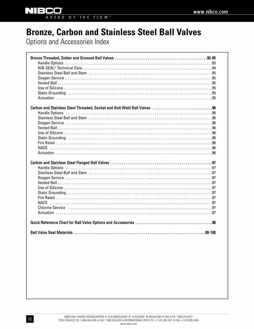
NIBCO INC. WORLD HEADQUARTERS • 1516 MIDDLEBURY ST. • ELKHART, IN 46516-4740 • USA • PH: 1.800.234.0227 TECH SERVICES PH: 1.888.446.4226 • FAX: 1.888.336.4226 • INTERNATIONAL OFFICE PH: +1.574.295.3221 • FAX: +1.574.295.3455
www.nibco.com
A H E A D O F T H E F L O W ™
wwwwww..nniibbccoo..ccoomm
92
Bronze, Carbon and Stainless Steel Ball ValvesOptions and Accessories Index
BBrroonnzzee TThhrreeaaddeedd,, SSoollddeerr aanndd GGrroooovveedd BBaallll VVaallvveess .. .. .. .. .. .. .. .. .. .. .. .. .. .. .. .. .. .. .. .. .. .. .. .. .. .. .. .. .. .. .. .. .. .. .. .. .. .. .. .. .. .. .. .. .. .. .. ..9933-9955Handle Options . . . . . . . . . . . . . . . . . . . . . . . . . . . . . . . . . . . . . . . . . . . . . . . . . . . . . . . . . . . . . . . . . . . . . . . . . . . .93NIB-SEAL® Technical Data . . . . . . . . . . . . . . . . . . . . . . . . . . . . . . . . . . . . . . . . . . . . . . . . . . . . . . . . . . . . . . . . . . .94Stainless Steel Ball and Stem . . . . . . . . . . . . . . . . . . . . . . . . . . . . . . . . . . . . . . . . . . . . . . . . . . . . . . . . . . . . . . . .95Oxygen Service . . . . . . . . . . . . . . . . . . . . . . . . . . . . . . . . . . . . . . . . . . . . . . . . . . . . . . . . . . . . . . . . . . . . . . . . . . . .95Vented Ball . . . . . . . . . . . . . . . . . . . . . . . . . . . . . . . . . . . . . . . . . . . . . . . . . . . . . . . . . . . . . . . . . . . . . . . . . . . . . . . .95Use of Silicone . . . . . . . . . . . . . . . . . . . . . . . . . . . . . . . . . . . . . . . . . . . . . . . . . . . . . . . . . . . . . . . . . . . . . . . . . . . . .95Static Grounding . . . . . . . . . . . . . . . . . . . . . . . . . . . . . . . . . . . . . . . . . . . . . . . . . . . . . . . . . . . . . . . . . . . . . . . . . . .95Actuation . . . . . . . . . . . . . . . . . . . . . . . . . . . . . . . . . . . . . . . . . . . . . . . . . . . . . . . . . . . . . . . . . . . . . . . . . . . . . . . . .95
CCaarrbboonn aanndd SSttaaiinnlleessss SStteeeell TThhrreeaaddeedd,, SSoocckkeett aanndd BBuutttt WWeelldd BBaallll VVaallvveess .. .. .. .. .. .. .. .. .. .. .. .. .. .. .. .. .. .. .. .. .. .. .. .. .. .. .. .. .. .. ..9966Handle Options . . . . . . . . . . . . . . . . . . . . . . . . . . . . . . . . . . . . . . . . . . . . . . . . . . . . . . . . . . . . . . . . . . . . . . . . . . . .96Stainless Steel Ball and Stem . . . . . . . . . . . . . . . . . . . . . . . . . . . . . . . . . . . . . . . . . . . . . . . . . . . . . . . . . . . . . . . .96Oxygen Service . . . . . . . . . . . . . . . . . . . . . . . . . . . . . . . . . . . . . . . . . . . . . . . . . . . . . . . . . . . . . . . . . . . . . . . . . . . .96Vented Ball . . . . . . . . . . . . . . . . . . . . . . . . . . . . . . . . . . . . . . . . . . . . . . . . . . . . . . . . . . . . . . . . . . . . . . . . . . . . . . . .96Use of Silicone . . . . . . . . . . . . . . . . . . . . . . . . . . . . . . . . . . . . . . . . . . . . . . . . . . . . . . . . . . . . . . . . . . . . . . . . . . . . .96Static Grounding . . . . . . . . . . . . . . . . . . . . . . . . . . . . . . . . . . . . . . . . . . . . . . . . . . . . . . . . . . . . . . . . . . . . . . . . . . .96Fire Rated . . . . . . . . . . . . . . . . . . . . . . . . . . . . . . . . . . . . . . . . . . . . . . . . . . . . . . . . . . . . . . . . . . . . . . . . . . . . . . . . .96NACE . . . . . . . . . . . . . . . . . . . . . . . . . . . . . . . . . . . . . . . . . . . . . . . . . . . . . . . . . . . . . . . . . . . . . . . . . . . . . . . . . . . .96Actuation . . . . . . . . . . . . . . . . . . . . . . . . . . . . . . . . . . . . . . . . . . . . . . . . . . . . . . . . . . . . . . . . . . . . . . . . . . . . . . . . .96
CCaarrbboonn aanndd SSttaaiinnlleessss SStteeeell FFllaannggeedd BBaallll VVaallvveess .. .. .. .. .. .. .. .. .. .. .. .. .. .. .. .. .. .. .. .. .. .. .. .. .. .. .. .. .. .. .. .. .. .. .. .. .. .. .. .. .. .. .. .. .. .. .. .. .. .. .. .. ..9977Handle Options . . . . . . . . . . . . . . . . . . . . . . . . . . . . . . . . . . . . . . . . . . . . . . . . . . . . . . . . . . . . . . . . . . . . . . . . . . . .97Stainless Steel Ball and Stem . . . . . . . . . . . . . . . . . . . . . . . . . . . . . . . . . . . . . . . . . . . . . . . . . . . . . . . . . . . . . . . .97Oxygen Service . . . . . . . . . . . . . . . . . . . . . . . . . . . . . . . . . . . . . . . . . . . . . . . . . . . . . . . . . . . . . . . . . . . . . . . . . . . .97Vented Ball . . . . . . . . . . . . . . . . . . . . . . . . . . . . . . . . . . . . . . . . . . . . . . . . . . . . . . . . . . . . . . . . . . . . . . . . . . . . . . . .97Use of Silicone . . . . . . . . . . . . . . . . . . . . . . . . . . . . . . . . . . . . . . . . . . . . . . . . . . . . . . . . . . . . . . . . . . . . . . . . . . . . .97Static Grounding . . . . . . . . . . . . . . . . . . . . . . . . . . . . . . . . . . . . . . . . . . . . . . . . . . . . . . . . . . . . . . . . . . . . . . . . . . .97Fire Rated . . . . . . . . . . . . . . . . . . . . . . . . . . . . . . . . . . . . . . . . . . . . . . . . . . . . . . . . . . . . . . . . . . . . . . . . . . . . . . . . .97NACE . . . . . . . . . . . . . . . . . . . . . . . . . . . . . . . . . . . . . . . . . . . . . . . . . . . . . . . . . . . . . . . . . . . . . . . . . . . . . . . . . . . .97Chlorine Service . . . . . . . . . . . . . . . . . . . . . . . . . . . . . . . . . . . . . . . . . . . . . . . . . . . . . . . . . . . . . . . . . . . . . . . . . . .97Actuation . . . . . . . . . . . . . . . . . . . . . . . . . . . . . . . . . . . . . . . . . . . . . . . . . . . . . . . . . . . . . . . . . . . . . . . . . . . . . . . . .97
QQuuiicckk RReeffeerreennccee CChhaarrtt ffoorr BBaallll VVaallvvee OOppttiioonnss aanndd AAcccceessssoorriieess .. .. .. .. .. .. .. .. .. .. .. .. .. .. .. .. .. .. .. .. .. .. .. .. .. .. .. .. .. .. .. .. .. .. .. .. .. .. .. ..9988
BBaallll VVaallvvee SSeeaatt MMaatteerriiaallss .. .. .. .. .. .. .. .. .. .. .. .. .. .. .. .. .. .. .. .. .. .. .. .. .. .. .. .. .. .. .. .. .. .. .. .. .. .. .. .. .. .. .. .. .. .. .. .. .. .. .. .. .. .. .. .. .. .. .. .. .. .. .. .. .. .. .. ..9999-110000
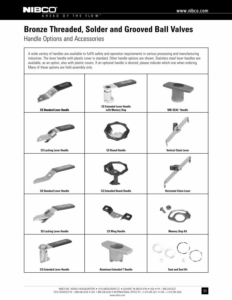
NIBCO INC. WORLD HEADQUARTERS • 1516 MIDDLEBURY ST. • ELKHART, IN 46516-4740 • USA • PH: 1.800.234.0227 TECH SERVICES PH: 1.888.446.4226 • FAX: 1.888.336.4226 • INTERNATIONAL OFFICE PH: +1.574.295.3221 • FAX: +1.574.295.3455
www.nibco.com
A H E A D O F T H E F L O W ™
wwwwww..nniibbccoo..ccoomm
93
Bronze Threaded, Solder and Grooved Ball ValvesHandle Options and Accessories
A wide variety of handles are available to fulfill safety and operation requirements in various processing and manufacturingindustries. The lever handle with plastic cover is standard. Other handle options are shown. Stainless steel lever handles areavailable, as an option, also with plastic covers. If an optional handle is desired, please indicate which one when ordering.Many of these options are field assembly only.
CS Standard Lever HandleCS Standard Lever Handle NIB-SEAL® HandleCS Extended Lever Handle
with Memory Stop
CS Locking Lever Handle Vertical Chain LeverCS Round Handle
SS Standard Lever Handle Horizontal Chain LeverCS Extended Round Handle
SS Locking Lever Handle Memory Stop KitCS Wing Handle
CS Extended Lever Handle Seat and Seal KitAluminum Extended T Handle
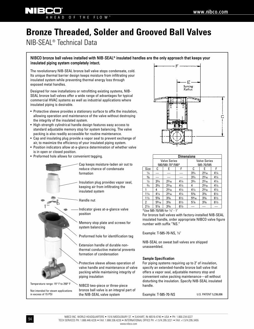
NIBCO INC. WORLD HEADQUARTERS • 1516 MIDDLEBURY ST. • ELKHART, IN 46516-4740 • USA • PH: 1.800.234.0227 TECH SERVICES PH: 1.888.446.4226 • FAX: 1.888.336.4226 • INTERNATIONAL OFFICE PH: +1.574.295.3221 • FAX: +1.574.295.3455
www.nibco.com
A H E A D O F T H E F L O W ™
wwwwww..nniibbccoo..ccoomm
94
Bronze Threaded, Solder and Grooved Ball ValvesNIB-SEAL® Technical Data
NNIIBBCCOO bbrroonnzzee bbaallll vvaallvveess iinnssttaalllleedd wwiitthh NNIIBB-SSEEAALL®® iinnssuullaatteedd hhaannddlleess aarree tthhee oonnllyy aapppprrooaacchh tthhaatt kkeeeeppss yyoouurriinnssuullaatteedd ppiippiinngg ssyysstteemm ccoommpplleetteellyy iinnttaacctt..
The revolutionary NIB-SEAL bronze ball valve stops condensate, cold.Its unique thermal barrier design keeps moisture from infiltrating yourinsulated system while preventing thermal energy loss throughexposed metal handles.
Designed for new installations or retrofitting existing systems, NIB-SEAL bronze ball valves offer a wide range of advantages for typicalcommercial HVAC systems as well as industrial applications whereinsulated piping is desirable.
• Protective sleeve provides a stationary surface to affix the insulation,allowing operation and maintenance of the valve without destroyingthe integrity of the insulated system.
• High-strength cylindrical handle design features easy access tostandard adjustable memory stop for system balancing. The valvepacking is also readily accessible for routine maintenance.
• Cap and insulating plug provide a vapor seal to prevent exchange ofair, to maximize the efficiency of your insulated piping system.
• Position indicators allow at-a-glance determination of whether valveis in open or closed position.
• Preformed hole allows for convenient tagging.
SSaammppllee SSppeecciiffiiccaattiioonnFor piping systems requiring up to 2" of insulation,specify an extended-handle bronze ball valve thatoffers a vapor seal, adjustable memory stop andconvenient valve packing maintenance—all withoutdisturbing the insulation. Specify NIB-SEAL insulatedhandle.
Example: T-585-70-NS
Cap keeps moisture-laden air out toreduce chance of condensateformation
Insulation plug provides vapor seal,keeping air from infiltrating theinsulated system
Handle nut
Indicator gives at-a-glance valveposition
Memory stop plate and screws forsystem balancing
Preformed hole for identification tag
Extension handle of durable non-thermal conductive material preventsformation of condensation
Protective sleeve allows operation ofvalve handle and maintenance of valvepacking while maintaining integrity ofpiping insulation
NIBCO two-piece or three-piecebronze ball valve is an integral part ofthe NIB-SEAL valve system
For bronze ball valves with factory-installed NIB-SEALinsulated handle, order appropriate NIBCO valve figurenumber with suffix ”NS.“
Example: T-585-70-NS, ¹⁄₂"
NIB-SEAL on sweat ball valves are shippedunassembled.
U.S. PATENT 5,236,006
Temperature range: 15° F to 250° F
Not intended for steam applicationsin excess of 15 PSI
DDiimmeennssiioonnssValve Series Valve Series
580/580-70*/590* 585-70/595Size C E F C E F¹⁄₄ — — — 3³⁄₄ 2³⁄₁₆ 4¹⁄₄
³⁄₈ — — — 3³⁄₄ 2³⁄₁₆ 4¹⁄₄
¹⁄₂ 3³⁄₄ 2³⁄₁₆ 4¹⁄₄ 3³⁄₄ 2³⁄₁₆ 4¹⁄₄
³⁄₄ 3³⁄₄ 2³⁄₁₆ 4¹⁄₄ 4 2³⁄₁₆ 4¹⁄₄
1 4 2³⁄₁₆ 4¹⁄₄ 4¹⁄₄ 2³⁄₁₆ 4¹⁄₄
1¹⁄₄ 4¹⁄₄ 2³⁄₁₆ 4¹⁄₄ 5³⁄₈ 3³⁄₈ 6¹⁄₂
1¹⁄₂ 5³⁄₈ 3³⁄₈ 6¹⁄₂ 5⁹⁄₁₆ 3³⁄₈ 6¹⁄₂
2 5⁹⁄₁₆ 3³⁄₈ 6¹⁄₂ 5⁷⁄₈ 3³⁄₈ 6¹⁄₂
2¹⁄₂ 5⁷⁄₈ 3³⁄₈ 6¹⁄₂ — — —*Use 585-70/595 for ¹⁄₄" - 1"

NIBCO INC. WORLD HEADQUARTERS • 1516 MIDDLEBURY ST. • ELKHART, IN 46516-4740 • USA • PH: 1.800.234.0227 TECH SERVICES PH: 1.888.446.4226 • FAX: 1.888.336.4226 • INTERNATIONAL OFFICE PH: +1.574.295.3221 • FAX: +1.574.295.3455
www.nibco.com
A H E A D O F T H E F L O W ™
wwwwww..nniibbccoo..ccoomm
95
Bronze Threaded, Solder and Grooved Ball ValvesOptions and Accessories (continued)
SSttaattiicc GGrroouunnddiinnggNIBCO provides static grounding standard on mostcarbon, stainless steel and bronze three-piece ballvalves. See product pages for availability.
AAccttuuaattiioonnEngineered with a modular approach, NIBCO‘s electricand pneumatic actuation systems give you flexibility toactuate new valves or retrofit existing valves. NIBCOelectric actuators, and NDA and NSR pneumaticactuators feature ISO standard mount and drive(exception is 800 series).
NNoo SSiilliiccoonnee UUsseedd –– SSiilliiccoonnee FFrreeee IIssssuueeAll NIBCO pressure-rated bronze gate, globe, checkand bronze ball valves are manufactured in NIBCO‘sNacogdoches, Texas, plant. Silicone is not used in thisplant in the production of valves or assembly of anycomponent parts of the above listed products.Note: Valves that are assembled and tested withoutsilicone lubricants in this plant have a potentialexposure to air-borne silicone as well as duringshipping after they leave the plant. Therefore, NIBCOcannot certify valves produced in the Nacogdochesplant to be 100% silicone free.
SSttaaiinnlleessss SStteeeell BBaallll aanndd SStteemm316 stainless steel ball and stem are available on manyNIBCO ball valves – see catalog specification sheets toidentify what valves are available or consult factory.
OOxxyyggeenn SSeerrvviicceeMany NIBCO ball valves are available for oxygenservice. Cleaned and packaged in durable, sealedplastic bags to avoid contamination. Oxygen cleanedvalves are not recommended for pressures exceeding200 PSI. The steps involved are as follows: 1) Cleanultrasonically all component parts with a degreaser ina warm water solution. 2) Rinse with warm water in anultrasonic bath. Rinse again in cold water. 3) Put allcomponent parts under black light for inspection of anycarbon. If carbon is found, repeat steps above. 4)Assemble and test valves. 5) Package the valves in asealed plastic bag to avoid contamination.
VVeenntteedd BBaallllNIBCO provides vented balls as standard on all carbonand stainless steel ball valves and bronze T-560s withstainless steel balls. For other bronze ball valves,vented balls may be available – see catalogspecification sheets to identify what valves areavailable or consult factory.
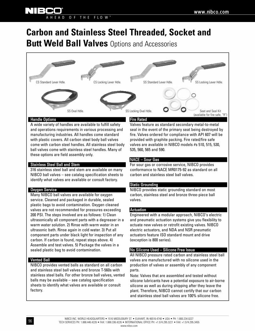
NIBCO INC. WORLD HEADQUARTERS • 1516 MIDDLEBURY ST. • ELKHART, IN 46516-4740 • USA • PH: 1.800.234.0227 TECH SERVICES PH: 1.888.446.4226 • FAX: 1.888.336.4226 • INTERNATIONAL OFFICE PH: +1.574.295.3221 • FAX: +1.574.295.3455
www.nibco.com
A H E A D O F T H E F L O W ™
wwwwww..nniibbccoo..ccoomm
96
Carbon and Stainless Steel Threaded, Socket andButt Weld Ball Valves Options and Accessories
HHaannddllee OOppttiioonnssA wide variety of handles are available to fulfill safetyand operations requirements in various processing andmanufacturing industries. All handles come standardwith plastic covers. All carbon steel body ball valvescome with carbon steel handles. All stainless steel bodyball valves come with stainless steel handles. Many ofthese options are field assembly only.
SSttaaiinnlleessss SStteeeell BBaallll aanndd SStteemm316 stainless steel ball and stem are available on manyNIBCO ball valves – see catalog specification sheets toidentify what valves are available or consult factory.
OOxxyyggeenn SSeerrvviicceeMany NIBCO ball valves are available for oxygenservice. Cleaned and packaged in durable, sealedplastic bags to avoid contamination. Oxygen cleanedvalves are not recommended for pressures exceeding200 PSI. The steps involved are as follows: 1) Cleanultrasonically all component parts with a degreaser in awarm water solution. 2) Rinse with warm water in anultrasonic bath. Rinse again in cold water. 3) Put allcomponent parts under black light for inspection of anycarbon. If carbon is found, repeat steps above. 4)Assemble and test valves. 5) Package the valves in asealed plastic bag to avoid contamination.
VVeenntteedd BBaallllNIBCO provides vented balls as standard on all carbonand stainless steel ball valves and bronze T-560s withstainless steel balls. For other bronze ball valves, ventedballs may be available – see catalog specificationsheets to identify what valves are available or consultfactory.
FFiirree RRaatteeddValves feature as standard secondary metal-to-metalseal in the event of the primary seat being destroyed byfire. Valves ordered for compliance with API 607 will beprovided with graphite packing. Fire rated/fire safevalves are available in NIBCO models #s 510, 515, 530,535, 560, 565 and 590.
NNAACCEE –– SSoouurr GGaassFor sour gas or corrosive service, NIBCO providesconformance to NACE MR0175-92 as standard on allcarbon and stainless steel ball valves.
SSttaattiicc GGrroouunnddiinnggNIBCO provides static grounding standard on mostcarbon, stainless steel and bronze three-piece ballvalves.
AAccttuuaattiioonnEngineered with a modular approach, NIBCO‘s electricand pneumatic actuation systems give you flexibility toactuate new valves or retrofit existing valves. NIBCOelectric actuators, and NDA and NSR pneumaticactuators feature ISO standard mount and drive(exception is 800 series).
NNoo SSiilliiccoonnee UUsseedd –– SSiilliiccoonnee FFrreeee IIssssuueeAll NIBCO pressure rated carbon and stainless steel ballvalves are manufactured with no silicone used in theproduction of valves or assembly of any componentparts.Note: Valves that are assembled and tested withoutsilicone lubricants have a potential exposure to air-bornesilicone as well as during shipping after they leave theplant. Therefore, NIBCO cannot certify that our carbonand stainless steel ball valves are 100% silicone free.
CS Standard Lever Hdle. SS Standard Lever Hdle.
SS Oval Hdle. SS Locking Oval Hdle. Seat and Seal Kit(available for fire safe, “R”)
SS Locking Lever Hdle.CS Locking Lever Hdle.
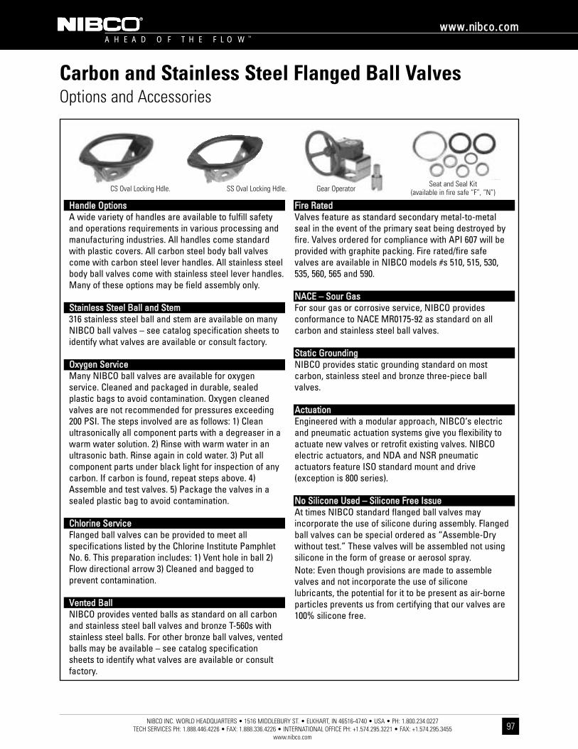
NIBCO INC. WORLD HEADQUARTERS • 1516 MIDDLEBURY ST. • ELKHART, IN 46516-4740 • USA • PH: 1.800.234.0227 TECH SERVICES PH: 1.888.446.4226 • FAX: 1.888.336.4226 • INTERNATIONAL OFFICE PH: +1.574.295.3221 • FAX: +1.574.295.3455
www.nibco.com
A H E A D O F T H E F L O W ™
wwwwww..nniibbccoo..ccoomm
97
Carbon and Stainless Steel Flanged Ball ValvesOptions and Accessories
HHaannddllee OOppttiioonnssA wide variety of handles are available to fulfill safetyand operations requirements in various processing andmanufacturing industries. All handles come standardwith plastic covers. All carbon steel body ball valvescome with carbon steel lever handles. All stainless steelbody ball valves come with stainless steel lever handles.Many of these options may be field assembly only.
SSttaaiinnlleessss SStteeeell BBaallll aanndd SStteemm316 stainless steel ball and stem are available on manyNIBCO ball valves – see catalog specification sheets toidentify what valves are available or consult factory.
OOxxyyggeenn SSeerrvviicceeMany NIBCO ball valves are available for oxygenservice. Cleaned and packaged in durable, sealedplastic bags to avoid contamination. Oxygen cleanedvalves are not recommended for pressures exceeding200 PSI. The steps involved are as follows: 1) Cleanultrasonically all component parts with a degreaser in awarm water solution. 2) Rinse with warm water in anultrasonic bath. Rinse again in cold water. 3) Put allcomponent parts under black light for inspection of anycarbon. If carbon is found, repeat steps above. 4)Assemble and test valves. 5) Package the valves in asealed plastic bag to avoid contamination.
CChhlloorriinnee SSeerrvviicceeFlanged ball valves can be provided to meet allspecifications listed by the Chlorine Institute PamphletNo. 6. This preparation includes: 1) Vent hole in ball 2)Flow directional arrow 3) Cleaned and bagged toprevent contamination.
VVeenntteedd BBaallllNIBCO provides vented balls as standard on all carbonand stainless steel ball valves and bronze T-560s withstainless steel balls. For other bronze ball valves, ventedballs may be available – see catalog specificationsheets to identify what valves are available or consultfactory.
FFiirree RRaatteeddValves feature as standard secondary metal-to-metalseal in the event of the primary seat being destroyed byfire. Valves ordered for compliance with API 607 will beprovided with graphite packing. Fire rated/fire safevalves are available in NIBCO models #s 510, 515, 530,535, 560, 565 and 590.
NNAACCEE –– SSoouurr GGaassFor sour gas or corrosive service, NIBCO providesconformance to NACE MR0175-92 as standard on allcarbon and stainless steel ball valves.
SSttaattiicc GGrroouunnddiinnggNIBCO provides static grounding standard on mostcarbon, stainless steel and bronze three-piece ballvalves.
AAccttuuaattiioonnEngineered with a modular approach, NIBCO‘s electricand pneumatic actuation systems give you flexibility toactuate new valves or retrofit existing valves. NIBCOelectric actuators, and NDA and NSR pneumaticactuators feature ISO standard mount and drive(exception is 800 series).
NNoo SSiilliiccoonnee UUsseedd –– SSiilliiccoonnee FFrreeee IIssssuueeAt times NIBCO standard flanged ball valves mayincorporate the use of silicone during assembly. Flangedball valves can be special ordered as “Assemble-Drywithout test.” These valves will be assembled not usingsilicone in the form of grease or aerosol spray.Note: Even though provisions are made to assemblevalves and not incorporate the use of siliconelubricants, the potential for it to be present as air-borneparticles prevents us from certifying that our valves are100% silicone free.
CS Oval Locking Hdle. SS Oval Locking Hdle. Gear OperatorSeat and Seal Kit
(available in fire safe “F”, “N”)
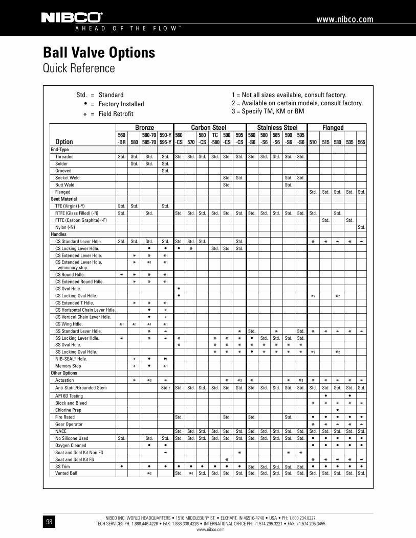
NIBCO INC. WORLD HEADQUARTERS • 1516 MIDDLEBURY ST. • ELKHART, IN 46516-4740 • USA • PH: 1.800.234.0227 TECH SERVICES PH: 1.888.446.4226 • FAX: 1.888.336.4226 • INTERNATIONAL OFFICE PH: +1.574.295.3221 • FAX: +1.574.295.3455
www.nibco.com
A H E A D O F T H E F L O W ™
wwwwww..nniibbccoo..ccoomm
98
Ball Valve OptionsQuick Reference
BBrroonnzzee CCaarrbboonn SStteeeell SSttaaiinnlleessss SStteeeell FFllaannggeedd556600 558800-7700 559900-YY 556600 558800 TTCC 559900 559955 556600 558800 558855 559900 559955
OOppttiioonn -BBRR 558800 558855-7700 559955-YY -CCSS 557700 -CCSS -558800 -CCSS -CCSS -SS66 -SS66 -SS66 -SS66 -SS66 551100 551155 553300 553355 556655EEnndd-TTyyppee
Threaded Std. Std. Std. Std. Std. Std. Std. Std. Std. Std. Std. Std. Std. Std. Std.Solder Std. Std. Std.Grooved Std.Socket Weld Std. Std. Std. Std.Butt Weld Std. Std.Flanged Std. Std. Std. Std. Std.
SSeeaatt MMaatteerriiaallTFE (Virgin) (-Y) Std. Std. Std.RTFE (Glass Filled) (-R) Std. Std. Std. Std. Std. Std. Std. Std. Std. Std. Std. Std. Std. Std. Std.FTFE (Carbon Graphite) (-F) Std. Std.Nylon (-N) Std.
HHaannddlleessCS Standard Lever Hdle. Std. Std. Std. Std. Std. Std. Std. Std. * * * * *CS Locking Lever Hdle. • • • * Std. Std. Std.CS Extended Lever Hdle. * * *1
CS Extended Lever Hdle. * *1 *1
w/memory stopCS Round Hdle. * * * *1
CS Extended Round Hdle. * * *1
CS Oval Hdle. •CS Locking Oval Hdle. • *2 *2
CS Extended T Hdle. * * *1
CS Horizontal Chain Lever Hdle. • *CS Vertical Chain Lever Hdle. • *CS Wing Hdle. *1 *1 *1 *1
SS Standard Lever Hdle. * * * Std. * Std. * * * * *SS Locking Lever Hdle. * * * * * * * • Std. Std. Std. Std.SS Oval Hdle. * * * * * * * * *SS Locking Oval Hdle. * * * • * * * * *2 *2
NIB-SEAL® Hdle. * • •1
Memory Stop * • *1
OOtthheerr OOppttiioonnssActuation * *3 * * *3 * * *3 * * * * *Anti-Static/Grounded Stem Std.2 Std. Std. Std. Std. Std. Std. Std. Std. Std. Std. Std. Std. Std. Std. Std. Std.
API 6D Testing • •Block and Bleed * * * * *Chlorine Prep •Fire Rated Std. Std. Std. Std. • • • • •Gear Operator * * * * *NACE Std. Std. Std. Std. Std. Std. Std. Std. Std. Std. Std. Std. Std. Std. Std. Std.No Silicone Used Std. Std. Std. Std. Std. Std. Std. Std. Std. Std. Std. Std. Std. Std. • • • • •Oxygen Cleaned • • • • • • •Seat and Seal Kit Non FS * * * *Seat and Seal Kit FS * * * * * *SS Trim • • • • • • • • • Std. Std. Std. Std. Std. • • • • •Vented Ball *2 Std. *1 Std. Std. Std. Std. Std. Std. Std. Std. Std. Std. Std. Std. Std. Std.
Std. = Standard• = Factory Installed
* = Field Retrofit
1 = Not all sizes available, consult factory.2 = Available on certain models, consult factory.3 = Specify TM, KM or BM
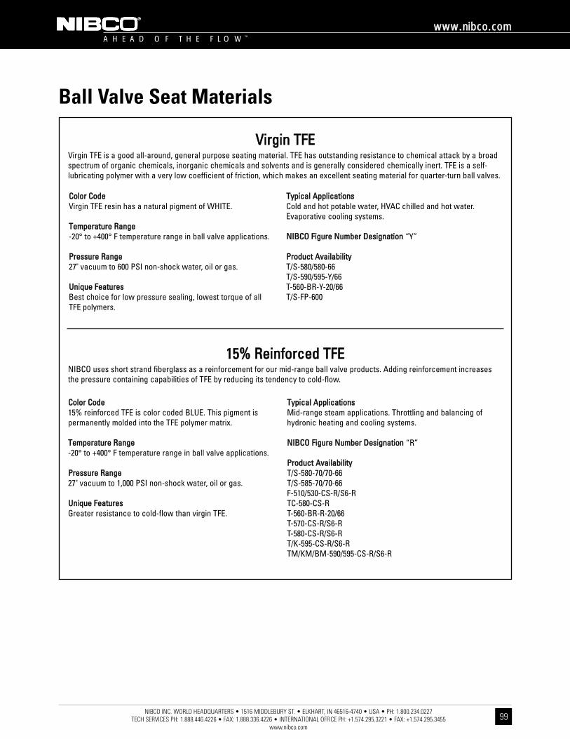
NIBCO INC. WORLD HEADQUARTERS • 1516 MIDDLEBURY ST. • ELKHART, IN 46516-4740 • USA • PH: 1.800.234.0227 TECH SERVICES PH: 1.888.446.4226 • FAX: 1.888.336.4226 • INTERNATIONAL OFFICE PH: +1.574.295.3221 • FAX: +1.574.295.3455
www.nibco.com
A H E A D O F T H E F L O W ™
wwwwww..nniibbccoo..ccoomm
99
Ball Valve Seat Materials
VViirrggiinn TTFFEEVirgin TFE is a good all-around, general purpose seating material. TFE has outstanding resistance to chemical attack by a broadspectrum of organic chemicals, inorganic chemicals and solvents and is generally considered chemically inert. TFE is a self-lubricating polymer with a very low coefficient of friction, which makes an excellent seating material for quarter-turn ball valves.
1155%% RReeiinnffoorrcceedd TTFFEENIBCO uses short strand fiberglass as a reinforcement for our mid-range ball valve products. Adding reinforcement increasesthe pressure containing capabilities of TFE by reducing its tendency to cold-flow.
CCoolloorr CCooddeeVirgin TFE resin has a natural pigment of WHITE.
TTeemmppeerraattuurree RRaannggee-20° to +400° F temperature range in ball valve applications.
PPrreessssuurree RRaannggee27" vacuum to 600 PSI non-shock water, oil or gas.
UUnniiqquuee FFeeaattuurreessBest choice for low pressure sealing, lowest torque of all TFE polymers.
TTyyppiiccaall AApppplliiccaattiioonnssCold and hot potable water, HVAC chilled and hot water.Evaporative cooling systems.
NNIIBBCCOO FFiigguurree NNuummbbeerr DDeessiiggnnaattiioonn “Y”
PPrroodduucctt AAvvaaiillaabbiilliittyyT/S-580/580-66T/S-590/595-Y/66T-560-BR-Y-20/66T/S-FP-600
CCoolloorr CCooddee15% reinforced TFE is color coded BLUE. This pigment ispermanently molded into the TFE polymer matrix.
TTeemmppeerraattuurree RRaannggee-20° to +400° F temperature range in ball valve applications.
PPrreessssuurree RRaannggee27" vacuum to 1,000 PSI non-shock water, oil or gas.
UUnniiqquuee FFeeaattuurreessGreater resistance to cold-flow than virgin TFE.
TTyyppiiccaall AApppplliiccaattiioonnssMid-range steam applications. Throttling and balancing ofhydronic heating and cooling systems.
NNIIBBCCOO FFiigguurree NNuummbbeerr DDeessiiggnnaattiioonn “R”
PPrroodduucctt AAvvaaiillaabbiilliittyyT/S-580-70/70-66T/S-585-70/70-66F-510/530-CS-R/S6-RTC-580-CS-RT-560-BR-R-20/66T-570-CS-R/S6-RT-580-CS-R/S6-RT/K-595-CS-R/S6-RTM/KM/BM-590/595-CS-R/S6-R

NIBCO INC. WORLD HEADQUARTERS • 1516 MIDDLEBURY ST. • ELKHART, IN 46516-4740 • USA • PH: 1.800.234.0227 TECH SERVICES PH: 1.888.446.4226 • FAX: 1.888.336.4226 • INTERNATIONAL OFFICE PH: +1.574.295.3221 • FAX: +1.574.295.3455
www.nibco.com
A H E A D O F T H E F L O W ™
wwwwww..nniibbccoo..ccoomm
100
Ball Valve Seat Materials
2255%% RReeiinnffoorrcceedd TTFFEENIBCO uses short strand fiberglass as a reinforcement for our higher pressure carbon steel and alloy ball valve products.Adding reinforcement increases the pressure containing capabilities of TFE by reducing its tendency to cold-flow.
CCaarrbboonn-FFiilllleedd TTFFEECarbon-filled TFE is an excellent seat material for steam applications as well as high efficiency oil-based thermal fluids. Otherfillers, including graphite, enable this seat material to have better cycle life than other filled or reinforced TFE seats. Chemicalresistance equal to other TFE and filled TFE products.
NNyylloonnNylon is predominantly used past the useful pressure range of TFE because of its ability to resist permanent deformation (or creep), and recovery after load.
CCoolloorr CCooddee25% reinforced TFE resin has a color code of RED. Thispigment is permanently molded into the TFE resin matrix.
TTeemmppeerraattuurree RRaannggee-20° to +400° F temperature range in ball valve applications.
PPrreessssuurree RRaannggee27" vacuum to 2,000 PSI non-shock water, oil or gas.
UUnniiqquuee FFeeaattuurreessImproved dimensional stability. Good wear properties.
TTyyppiiccaall AApppplliiccaattiioonnssSteam service, natural and bottled gas distribution.
NNIIBBCCOO FFiigguurree NNuummbbeerr DDeessiiggnnaattiioonn “R”
PPrroodduucctt AAvvaaiillaabbiilliittyyT-560-CS-R/S6-R
CCoolloorr CCooddeeCarbon filled TFE has a natural pigment of BLACK.
TTeemmppeerraattuurree RRaannggee-20° to +500° F temperature range in ball valve applications.
PPrreessssuurree RRaannggee27" vacuum to 2,000 PSI non-shock water, oil or gas.
UUnniiqquuee FFeeaattuurreessHigher cycle life than other TFE resins.
TTyyppiiccaall AApppplliiccaattiioonnssHigh pressure steam and thermal fluids.
NNIIBBCCOO FFiigguurree NNuummbbeerr DDeessiiggnnaattiioonn“F” (in flanged) and “C” (in threaded).
PPrroodduucctt AAvvaaiillaabbiilliittyyF-510/530-CS-F/S6-F-66F-515/535-CS-F/S6-F-66AT-585-70-66TM-585-70-66
CCoolloorr CCooddeeNatural or Black
TTeemmppeerraattuurree RRaannggee-20° to +160° F temperature range in ball valve applications.
PPrreessssuurree RRaannggee27" vacuum to 3,000 PSI.
UUnniiqquuee FFeeaattuurreessUsed in oil and gas transmission.
TTyyppiiccaall AApppplliiccaattiioonnssGrease, oils, alphitic and aromatic hydrocarbons, paint,cosmetics, and detergents.
NNIIBBCCOO FFiigguurree NNuummbbeerr DDeessiiggnnaattiioonn “N”
PPrroodduucctt AAvvaaiillaabbiilliittyyF-565-CS-N/S6-N-66

NIBCO INC. WORLD HEADQUARTERS • 1516 MIDDLEBURY ST. • ELKHART, IN 46516-4740 • USA • PH: 1.800.234.0227 TECH SERVICES PH: 1.888.446.4226 • FAX: 1.888.336.4226 • INTERNATIONAL OFFICE PH: +1.574.295.3221 • FAX: +1.574.295.3455
www.nibco.com
A H E A D O F T H E F L O W ™
wwwwww..nniibbccoo..ccoomm
101
System Control Products IndexBBaallll VVaallvvee AAccttuuaattiioonn aanndd CCoonnttrrooll .. .. .. .. .. .. .. .. .. .. .. .. .. .. .. .. .. .. .. .. .. .. .. .. .. .. .. .. .. .. .. .. .. .. .. .. .. .. .. .. .. .. .. .. .. .. .. .. .. .. .. .. .. .. .. .. .. .. .. .. .. .. .. ..110022
CCiirrccuuiitt BBaallaanncciinngg VVaallvveess .. .. .. .. .. .. .. .. .. .. .. .. .. .. .. .. .. .. .. .. .. .. .. .. .. .. .. .. .. .. .. .. .. .. .. .. .. .. .. .. .. .. .. .. .. .. .. .. .. .. .. .. .. .. .. .. .. .. .. .. .. .. .. .. .. .. .. .. .. .. ..110033
BBaallll VVaallvvee AAccttuuaattiioonn DDaattaa SShheeeett .. .. .. .. .. .. .. .. .. .. .. .. .. .. .. .. .. .. .. .. .. .. .. .. .. .. .. .. .. .. .. .. .. .. .. .. .. .. .. .. .. .. .. .. .. .. .. .. .. .. .. .. .. .. .. .. .. .. .. .. .. .. .. .. ..110044
SSyysstteemm CCoonnttrrooll BBaallll VVaallvveess .. .. .. .. .. .. .. .. .. .. .. .. .. .. .. .. .. .. .. .. .. .. .. .. .. .. .. .. .. .. .. .. .. .. .. .. .. .. .. .. .. .. .. .. .. .. .. .. .. .. .. .. .. .. .. .. .. .. .. .. .. .. .. .. .. ..110055-110066
TToorrqquuee CChhaarrttss .. .. .. .. .. .. .. .. .. .. .. .. .. .. .. .. .. .. .. .. .. .. .. .. .. .. .. .. .. .. .. .. .. .. .. .. .. .. .. .. .. .. .. .. .. .. .. .. .. .. .. .. .. .. .. .. .. .. .. .. .. .. .. .. .. .. .. .. .. .. .. .. .. .. .. .. ..110077-110088
AAccttuuaattoorr MMoouunnttiinngg DDaattaa .. .. .. .. .. .. .. .. .. .. .. .. .. .. .. .. .. .. .. .. .. .. .. .. .. .. .. .. .. .. .. .. .. .. .. .. .. .. .. .. .. .. .. .. .. .. .. .. .. .. .. .. .. .. .. .. .. .. .. .. .. .. .. .. .. .. .. ..110099-111122Three-Way Bronze Full Port T/S-585-W3 Series . . . . . . . . . . . . . . . . . . . . . . . . . . . . . . . . . . . . . . . . . . . . . . . .109Two-Piece SS/CS Reduced Port T-580-S6/TC-580-CS-R . . . . . . . . . . . . . . . . . . . . . . . . . . . . . . . . . . . . . . . . . .110Three-Piece Bronze Reduced/Full Port T/S-590/595 Series . . . . . . . . . . . . . . . . . . . . . . . . . . . . . . . . . . . . . . .111Three-Piece SS/CS Full Port TM/KM/BM-590/595 Series . . . . . . . . . . . . . . . . . . . . . . . . . . . . . . . . . . . . . . . . .112
For individual sizing of actuators to ball valves consult your NIBCO technical service representative.
TToorrqquuee::Torque is the effective rotary power required by a valve and/or delivered by an actuator. Torque is normally stated in inch/pounds or foot/pounds. This turning force in a ball valve is affected by three factors:
1. Friction of the ball to seat2. Bearing friction (packing)3. Dynamic forces (pressure)
Torque = Distance x Force
BBrreeaakkaawwaayy TToorrqquuee is the total of the three factors listed above. This value is normally the highest required torque tooperate a valve and is used in sizing actuators. The torque values listed in the corresponding charts are valid forwater and lubricating fluids at ambient temperature. For dry and non-lubricating fluids, consult your NIBCOtechnical service representative.
Actuator mounting dimensions for flanged ball valves, see pages 77-84.
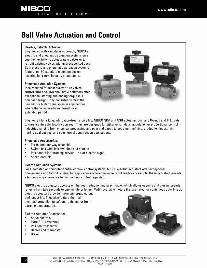
NIBCO INC. WORLD HEADQUARTERS • 1516 MIDDLEBURY ST. • ELKHART, IN 46516-4740 • USA • PH: 1.800.234.0227 TECH SERVICES PH: 1.888.446.4226 • FAX: 1.888.336.4226 • INTERNATIONAL OFFICE PH: +1.574.295.3221 • FAX: +1.574.295.3455
www.nibco.com
A H E A D O F T H E F L O W ™
wwwwww..nniibbccoo..ccoomm
102
Ball Valve Actuation and ControlFFlleexxiibbllee,, RReelliiaabbllee AAccttuuaattiioonnEngineered with a modular approach, NIBCO‘selectric and pneumatic actuation systems giveyou the flexibility to actuate new valves or toretrofit existing valves with unprecedented ease.Both electric and pneumatic actuation systemsfeature an ISO standard mounting design,assuring long-term industry acceptance.
PPnneeuummaattiicc AAccttuuaattiioonn SSyysstteemmssIdeally suited for most quarter-turn valves,NIBCO NDA and NSR pneumatic actuators offerexceptional starting and ending torque in acompact design. They consistently meet thedemand for high torque, even in applicationswhere the valve has been closed for anextended period.
Engineered for a long, lubrication-free service life, NIBCO NDA and NSR actuators combine O-rings and TFE sealsto create a durable, low-friction seal. They are designed for either on-off duty, modulation or proportional control inindustries ranging from chemical processing and pulp and paper, to petroleum refining, production industries,marine applications, and commercial construction applications.
PPnneeuummaattiicc AAcccceessssoorriieess::• Three and four way solenoids• Switch box with limit switches and beacon• Positioners for throttling service—air or electric signal• Speed controls
EElleeccttrriicc AAccttuuaattiioonn SSyysstteemmssFor automated or computer-controlled flow control systems, NIBCO electric actuators offer exceptionalconvenience and flexibility. Ideal for applications where the valve is not readily accessible, these actuators providea labor-saving alternative to manual flow control regulation.
NIBCO electric actuators operate on the gear reduction motor principle, which allows opening and closing speedsranging from two seconds to one minute or longer. With reversible motors that are rated for continuous duty, NIBCOelectric actuators provide maximum torque outputand longer life. They also feature thermaloverload protection to safeguard the motor fromextreme temperatures.
Electric Actuator Accessories:• Servo controls• Extra SPDT switches• Position transmitter• Heater and thermostat• Brake
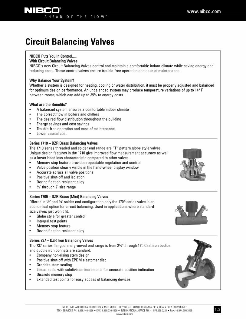
NIBCO INC. WORLD HEADQUARTERS • 1516 MIDDLEBURY ST. • ELKHART, IN 46516-4740 • USA • PH: 1.800.234.0227 TECH SERVICES PH: 1.888.446.4226 • FAX: 1.888.336.4226 • INTERNATIONAL OFFICE PH: +1.574.295.3221 • FAX: +1.574.295.3455
www.nibco.com
A H E A D O F T H E F L O W ™
wwwwww..nniibbccoo..ccoomm
103
Circuit Balancing ValvesNNIIBBCCOO PPuuttss YYoouu IInn CCoonnttrrooll..........WWiitthh CCiirrccuuiitt BBaallaanncciinngg VVaallvveessNIBCO's new Circuit Balancing Valves control and maintain a comfortable indoor climate while saving energy andreducing costs. These control valves ensure trouble-free operation and ease of maintenance.
WWhhyy BBaallaannccee YYoouurr SSyysstteemm??Whether a system is designed for heating, cooling or water distribution, it must be properly adjusted and balancedfor optimum design performance. An unbalanced system may produce temperature variations of up to 14° Fbetween rooms, which can add up to 35% to energy costs.
WWhhaatt aarree tthhee BBeenneeffiittss??• A balanced system ensures a comfortable indoor climate• The correct flow in boilers and chillers• The desired flow distribution throughout the building• Energy savings and cost savings• Trouble-free operation and ease of maintenance• Lower capital cost
SSeerriieess 11771100 –– DDZZRR BBrraassss BBaallaanncciinngg VVaallvveessThe 1710 series threaded and solder end range are ”T“ pattern globe style valves.Unique design features in the 1710 give improved flow measurement accuracy as wellas a lower head loss characteristic compared to other valves.• Memory stop feature provides repeatable regulation and control• Valve position clearly visible in the hand-wheel display window• Accurate across all valve positions• Positive shut-off and isolation• Dezincification resistant alloy• ¹⁄₂" through 2" size range
SSeerriieess 11770099 –– DDZZRR BBrraassss ((MMiinnii)) BBaallaanncciinngg VVaallvveessOffered in ¹⁄₂" and ³⁄₄" solder end configuration only the 1709 series valve is aneconomical option for circuit balancing. Used in applications where standardsize valves just won't fit.• Globe style for greater control• Integral test points• Memory stop feature• Dezincification resistant alloy
SSeerriieess 773377 –– DDZZRR IIrroonn BBaallaanncciinngg VVaallvveessThe 737 series flanged and grooved end range is from 2¹⁄₂" through 12". Cast iron bodiesand ductile iron bonnets are standard.• Company non-rising stem design• Positive shut-off with EPDM elastomer disc• Graphite stem sealing• Linear scale with subdivision increments for accurate position indication• Discrete memory stop• Extended test points for easy access of balancing devices
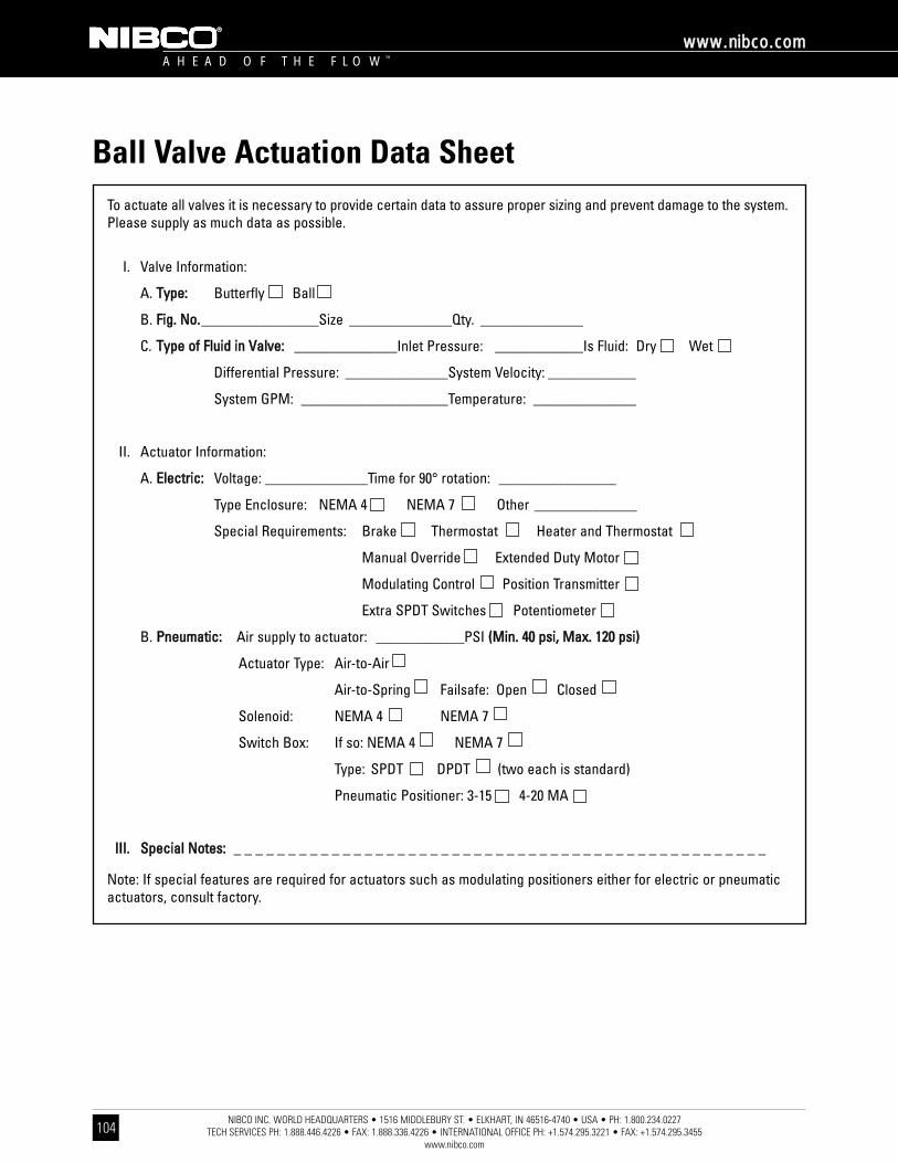
NIBCO INC. WORLD HEADQUARTERS • 1516 MIDDLEBURY ST. • ELKHART, IN 46516-4740 • USA • PH: 1.800.234.0227 TECH SERVICES PH: 1.888.446.4226 • FAX: 1.888.336.4226 • INTERNATIONAL OFFICE PH: +1.574.295.3221 • FAX: +1.574.295.3455
www.nibco.com
A H E A D O F T H E F L O W ™
wwwwww..nniibbccoo..ccoomm
104
Ball Valve Actuation Data SheetTo actuate all valves it is necessary to provide certain data to assure proper sizing and prevent damage to the system.Please supply as much data as possible.
I. Valve Information:
A. TTyyppee:: Butterfly Ball
B. FFiigg.. NNoo..________________Size ______________Qty. ______________
C. TTyyppee ooff FFlluuiidd iinn VVaallvvee:: ______________Inlet Pressure: ____________Is Fluid: Dry Wet
Differential Pressure: ______________System Velocity: ____________
System GPM: ____________________Temperature: ______________
II. Actuator Information:
A. EElleeccttrriicc:: Voltage: ______________Time for 90° rotation: ________________
Type Enclosure: NEMA 4 NEMA 7 Other ______________
Special Requirements: Brake Thermostat Heater and Thermostat
Manual Override Extended Duty Motor
Modulating Control Position Transmitter
Extra SPDT Switches Potentiometer
B. PPnneeuummaattiicc:: Air supply to actuator: ____________PSI ((MMiinn.. 4400 ppssii,, MMaaxx.. 112200 ppssii))
Actuator Type: Air-to-Air
Air-to-Spring Failsafe: Open Closed
Solenoid: NEMA 4 NEMA 7
Switch Box: If so: NEMA 4 NEMA 7
Type: SPDT DPDT (two each is standard)
Pneumatic Positioner: 3-15 4-20 MA
IIIIII.. SSppeecciiaall NNootteess:: _ _ _ _ _ _ _ _ _ _ _ _ _ _ _ _ _ _ _ _ _ _ _ _ _ _ _ _ _ _ _ _ _ _ _ _ _ _ _ _ _ _ _ _ _ _ _ _ _
Note: If special features are required for actuators such as modulating positioners either for electric or pneumaticactuators, consult factory.

NIBCO INC. WORLD HEADQUARTERS • 1516 MIDDLEBURY ST. • ELKHART, IN 46516-4740 • USA • PH: 1.800.234.0227 TECH SERVICES PH: 1.888.446.4226 • FAX: 1.888.336.4226 • INTERNATIONAL OFFICE PH: +1.574.295.3221 • FAX: +1.574.295.3455
www.nibco.com
A H E A D O F T H E F L O W ™
wwwwww..nniibbccoo..ccoomm
105
Bronze Ball Valves for System Controls ApplicationsTwo-Piece Body • Full Port • 316SS Trim • Blowout-Proof Stem Pre-assembled with NIBCO Series 2000 Thermoplastic Housed Pneumatic Actuator
600 PSI/41.4 Bar Non-Shock Cold Working Pressure
CONFORMS TO MSS SP-110, ACTUATOR MOUNT PER ISO 5211
TM-585-70-66-AP
MATERIAL LISTPART SPECIFICATION
1. Stem Stainless Steel ASTM A 276 Type 3162. O-Ring Fluoroelastomer3. Thrust Washer Reinforced TFE4. Seat Ring (2) Carbon Filled TFE5. Ball (Vented) Stainless Steel ASTM A 276 Type 316
or ASTM A 351 Type CF8M6. Body Bronze ASTM B 584 Alloy C844007. Body End Piece Bronze ASTM B 584 Alloy C844008. Actuator Glass Reinforced Polyarylamide
SSiizzee PPrreessssuurree FFiigguurree NNuummbbeerr DDoouubbllee AAccttiinngg MMoouunntt KKiitt FFiigguurree NNuummbbeerr SSpprriinngg RReettuurrnn MMoouunntt KKiittAAccttuuaattoorr AAccttuuaattoorr
¹⁄₂" 100PSI T-585-70-66-AP-NDA NDA2011F03 T117042 T-585-70-60-AP-NSR NSR2011F03 3+3 T117042¹⁄₂" 600PSI T-585-70-66-AP-NDA NDA2011F03 T117042 T-585-70-66-AP-NSR NSR2011F03 3+3 T117042³⁄₄" 100PSI T-585-70-66-AP-NDA NDA2011F03 T117042 T-585-70-66-AP-NSR NSR2011F03 3+3 T117042³⁄₄" 600PSI T-585-70-66-AP-NDA NDA2011F03 T117042 T-585-70-66-AP-NSR NSR2011F03 3+3 T1170421" 100PSI T-585-70-66-AP-NDA NDA2011F04 T117043 T-585-70-66-AP-NSR NSR2011F04 3+3 T1170431" 600PSI T-585-70-66-AP-NDA NDA2011F04 T117043 T-585-70-66-AP-NSR NSR2011F04 3+3 T117043
Note:
1. Spring Return Actuators are set for 80PSI Air Supply Standard
2. Spring Return Actuators are set for Fail to Close as Standard
3. Specify Size and Figure Number when Ordering

NIBCO INC. WORLD HEADQUARTERS • 1516 MIDDLEBURY ST. • ELKHART, IN 46516-4740 • USA • PH: 1.800.234.0227 TECH SERVICES PH: 1.888.446.4226 • FAX: 1.888.336.4226 • INTERNATIONAL OFFICE PH: +1.574.295.3221 • FAX: +1.574.295.3455
www.nibco.com
A H E A D O F T H E F L O W ™
wwwwww..nniibbccoo..ccoomm
106
Bronze Ball Valves for System Controls ApplicationsTwo-Piece Body • Reduced Port • 316SS Trim • Blowout-Proof Stem Reduced Orifice Ball for HVAC Control Applications
600 PSI/41.4 Bar Non-Shock Cold Working Pressure
CONFORMS TO MSS SP-110, ACTUATOR MOUNT PER ISO 5211
TM-585-CVShown with 24 VDC
Electric Actuator and Universal Mount
MATERIAL LISTPART SPECIFICATION
1. Stem Stainless Steel ASTM A 276 Type 3162. O-Ring (2) Fluoroelastomer3. Thrust Washer Reinforced TFE4. Seat Ring (2) Carbon Filled TFE5. Ball Stainless Steel ASTM A 276 Type 316
or ASTM A 351 Type CF8M6. Body Bronze ASTM B 584 Alloy C844007. Body End Piece Bronze ASTM B 584 Alloy C84400
DIMENSIONS—WEIGHTS—QUANTITIESDimensions
Size Flange A B C D E F G H TM-585-70-66 MasterIn. mm. Size In. mm. In. mm. In. mm. In. mm. In. mm. In. mm. In. mm. In. mm. Lbs. Kg. Ctn. Qty.¹⁄₂ 15 F03 .50 13 2.43 62 1.10 28 .35 9 1.42 36 .22 51 .39 10 .12 3 .82 .37 50³⁄₄ 20 F03 .75 19 2.94 75 1.37 35 .35 9 1.42 36 .22 51 .39 10 .12 3 1.23 .56 25
TM-585-CV
Reduced Orifice Ball – CV RatingsSize Figure # Material # CV¹⁄₂" TM-585-CV-200 WL95H16 1¹⁄₂" TM-585-CV-300 WL95H26 3¹⁄₂" TM-585-CV-400 WL95H36 7¹⁄₂" TM-585-CV-450 WL95H46 10³⁄₄" TM-585-CV-640 WL95H18 20
Standard ValveSize Figure # Material # CV¹⁄₂" TM-585-70-66 — 15.3³⁄₄" TM-585-70-66 — 30.4
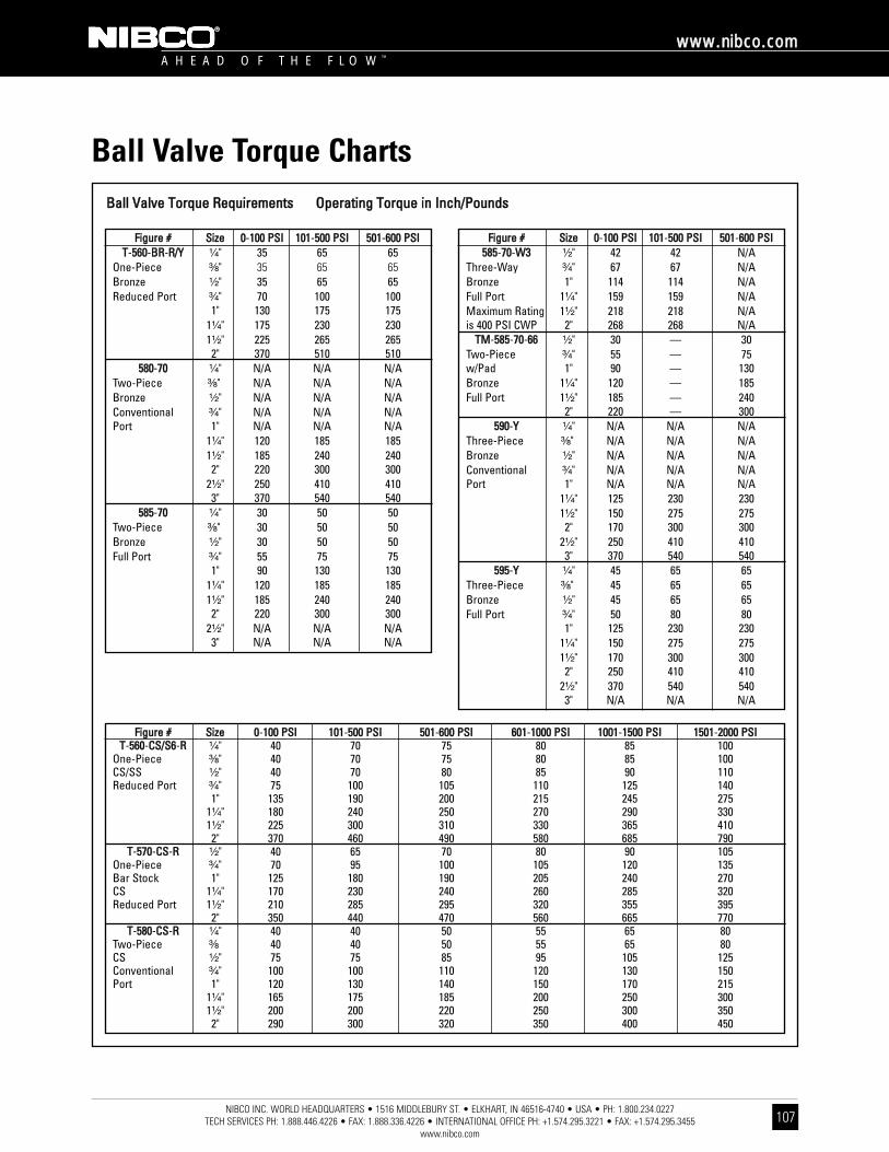
NIBCO INC. WORLD HEADQUARTERS • 1516 MIDDLEBURY ST. • ELKHART, IN 46516-4740 • USA • PH: 1.800.234.0227 TECH SERVICES PH: 1.888.446.4226 • FAX: 1.888.336.4226 • INTERNATIONAL OFFICE PH: +1.574.295.3221 • FAX: +1.574.295.3455
www.nibco.com
A H E A D O F T H E F L O W ™
wwwwww..nniibbccoo..ccoomm
107
Ball Valve Torque ChartsBBaallll VVaallvvee TToorrqquuee RReeqquuiirreemmeennttss OOppeerraattiinngg TToorrqquuee iinn IInncchh//PPoouunnddss
FFiigguurree ## SSiizzee 00-110000 PPSSII 110011-550000 PPSSII 550011-660000 PPSSIITT-556600-BBRR-RR//YY ¹⁄₄" 35 65 65
One-Piece ³⁄₈" 35 65 65Bronze ¹⁄₂" 35 65 65Reduced Port ³⁄₄" 70 100 100
1" 130 175 1751¹⁄₄" 175 230 2301¹⁄₂" 225 265 2652" 370 510 510
558800-7700 ¹⁄₄" N/A N/A N/ATwo-Piece ³⁄₈" N/A N/A N/ABronze ¹⁄₂" N/A N/A N/AConventional ³⁄₄" N/A N/A N/APort 1" N/A N/A N/A
1¹⁄₄" 120 185 1851¹⁄₂" 185 240 2402" 220 300 300
2¹⁄₂" 250 410 4103" 370 540 540
558855-7700 ¹⁄₄" 30 50 50Two-Piece ³⁄₈" 30 50 50Bronze ¹⁄₂" 30 50 50Full Port ³⁄₄" 55 75 75
1" 90 130 1301¹⁄₄" 120 185 1851¹⁄₂" 185 240 2402" 220 300 300
2¹⁄₂" N/A N/A N/A3" N/A N/A N/A
FFiigguurree ## SSiizzee 00-110000 PPSSII 110011-550000 PPSSII 550011-660000 PPSSII558855-7700-WW33 ¹⁄₂" 42 42 N/A
Three-Way ³⁄₄" 67 67 N/ABronze 1" 114 114 N/AFull Port 1¹⁄₄" 159 159 N/AMaximum Rating 1¹⁄₂" 218 218 N/Ais 400 PSI CWP 2" 268 268 N/A
TTMM-558855-7700-6666 ¹⁄₂" 30 — 30Two-Piece ³⁄₄" 55 — 75w/Pad 1" 90 — 130Bronze 1¹⁄₄" 120 — 185Full Port 1¹⁄₂" 185 — 240
2" 220 — 300559900-YY ¹⁄₄" N/A N/A N/A
Three-Piece ³⁄₈" N/A N/A N/ABronze ¹⁄₂" N/A N/A N/AConventional ³⁄₄" N/A N/A N/APort 1" N/A N/A N/A
1¹⁄₄" 125 230 2301¹⁄₂" 150 275 2752" 170 300 300
2¹⁄₂" 250 410 4103" 370 540 540
559955-YY ¹⁄₄" 45 65 65Three-Piece ³⁄₈" 45 65 65Bronze ¹⁄₂" 45 65 65Full Port ³⁄₄" 50 80 80
1" 125 230 2301¹⁄₄" 150 275 2751¹⁄₂" 170 300 3002" 250 410 410
2¹⁄₂" 370 540 5403" N/A N/A N/A
FFiigguurree ## SSiizzee 00-110000 PPSSII 110011-550000 PPSSII 550011-660000 PPSSII 660011-11000000 PPSSII 11000011-11550000 PPSSII 11550011-22000000 PPSSIITT-556600-CCSS//SS66-RR ¹⁄₄" 40 70 75 80 85 100
One-Piece ³⁄₈" 40 70 75 80 85 100CS/SS ¹⁄₂" 40 70 80 85 90 110Reduced Port ³⁄₄" 75 100 105 110 125 140
1" 135 190 200 215 245 2751¹⁄₄" 180 240 250 270 290 3301¹⁄₂" 225 300 310 330 365 4102" 370 460 490 580 685 790
TT-557700-CCSS-RR ¹⁄₂" 40 65 70 80 90 105One-Piece ³⁄₄" 70 95 100 105 120 135Bar Stock 1" 125 180 190 205 240 270CS 1¹⁄₄" 170 230 240 260 285 320Reduced Port 1¹⁄₂" 210 285 295 320 355 395
2" 350 440 470 560 665 770TT-558800-CCSS-RR ¹⁄₄" 40 40 50 55 65 80
Two-Piece ³⁄₈ 40 40 50 55 65 80CS ¹⁄₂" 75 75 85 95 105 125Conventional ³⁄₄" 100 100 110 120 130 150Port 1" 120 130 140 150 170 215
1¹⁄₄" 165 175 185 200 250 3001¹⁄₂" 200 200 220 250 300 3502" 290 300 320 350 400 450
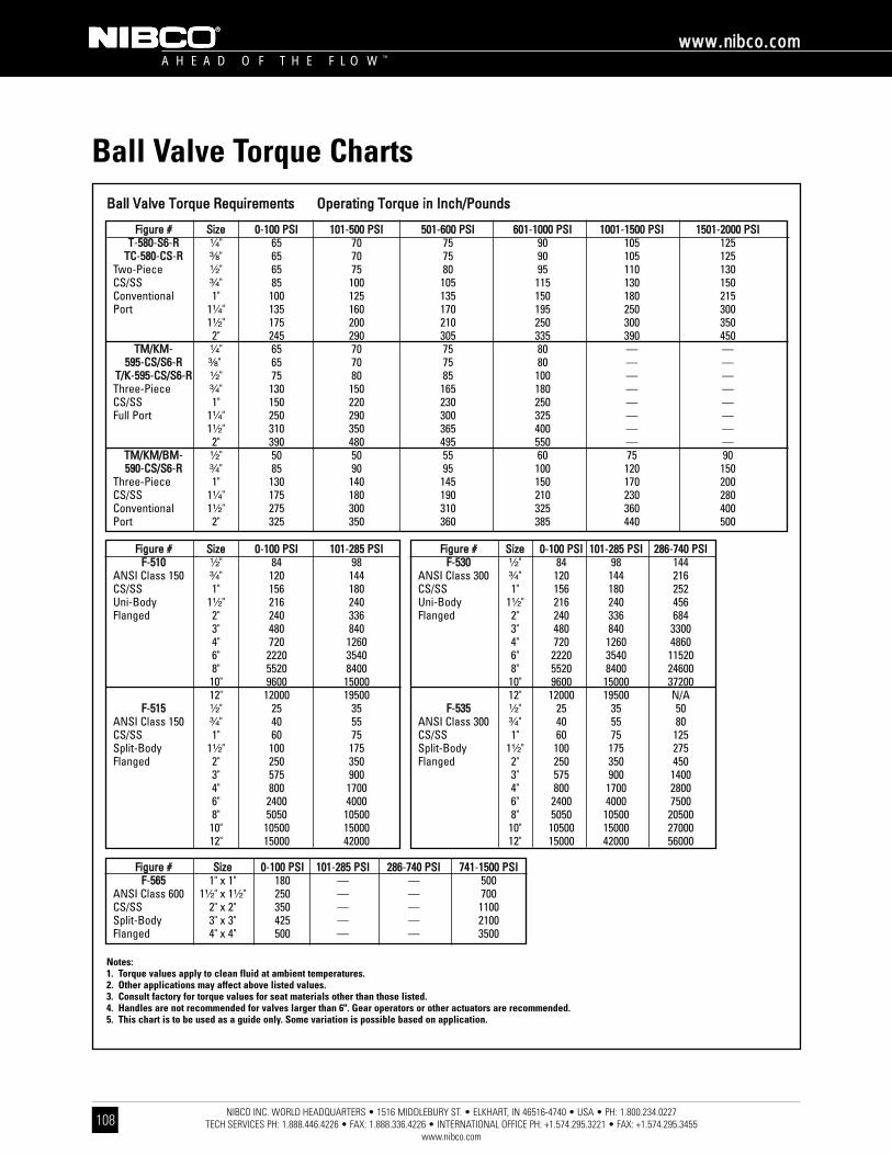
NIBCO INC. WORLD HEADQUARTERS • 1516 MIDDLEBURY ST. • ELKHART, IN 46516-4740 • USA • PH: 1.800.234.0227 TECH SERVICES PH: 1.888.446.4226 • FAX: 1.888.336.4226 • INTERNATIONAL OFFICE PH: +1.574.295.3221 • FAX: +1.574.295.3455
www.nibco.com
A H E A D O F T H E F L O W ™
wwwwww..nniibbccoo..ccoomm
108
Ball Valve Torque ChartsBBaallll VVaallvvee TToorrqquuee RReeqquuiirreemmeennttss OOppeerraattiinngg TToorrqquuee iinn IInncchh//PPoouunnddss
FFiigguurree ## SSiizzee 00-110000 PPSSII 110011-550000 PPSSII 550011-660000 PPSSII 660011-11000000 PPSSII 11000011-11550000 PPSSII 11550011-22000000 PPSSIITT-558800-SS66-RR ¹⁄₄" 65 70 75 90 105 125
TTCC-558800-CCSS-RR ³⁄₈" 65 70 75 90 105 125Two-Piece ¹⁄₂" 65 75 80 95 110 130CS/SS ³⁄₄" 85 100 105 115 130 150Conventional 1" 100 125 135 150 180 215Port 1¹⁄₄" 135 160 170 195 250 300
1¹⁄₂" 175 200 210 250 300 3502" 245 290 305 335 390 450
TTMM//KKMM- ¹⁄₄" 65 70 75 80 — —559955-CCSS//SS66-RR ³⁄₈" 65 70 75 80 — —
TT//KK-559955-CCSS//SS66-RR ¹⁄₂" 75 80 85 100 — —Three-Piece ³⁄₄" 130 150 165 180 — —CS/SS 1" 150 220 230 250 — —Full Port 1¹⁄₄" 250 290 300 325 — —
1¹⁄₂" 310 350 365 400 — —2" 390 480 495 550 — —
TTMM//KKMM//BBMM- ¹⁄₂" 50 50 55 60 75 90559900-CCSS//SS66-RR ³⁄₄" 85 90 95 100 120 150
Three-Piece 1" 130 140 145 150 170 200CS/SS 1¹⁄₄" 175 180 190 210 230 280Conventional 1¹⁄₂" 275 300 310 325 360 400Port 2" 325 350 360 385 440 500
FFiigguurree ## SSiizzee 00-110000 PPSSII 110011-228855 PPSSIIFF-551100 ¹⁄₂" 84 98
ANSI Class 150 ³⁄₄" 120 144CS/SS 1" 156 180Uni-Body 1¹⁄₂" 216 240Flanged 2" 240 336
3" 480 8404" 720 12606" 2220 35408" 5520 840010" 9600 1500012" 12000 19500
FF-551155 ¹⁄₂" 25 35ANSI Class 150 ³⁄₄" 40 55CS/SS 1" 60 75Split-Body 1¹⁄₂" 100 175Flanged 2" 250 350
3" 575 9004" 800 17006" 2400 40008" 5050 1050010" 10500 1500012" 15000 42000
FFiigguurree ## SSiizzee 00-110000 PPSSII 110011-228855 PPSSII 228866-774400 PPSSIIFF-553300 ¹⁄₂" 84 98 144
ANSI Class 300 ³⁄₄" 120 144 216CS/SS 1" 156 180 252Uni-Body 1¹⁄₂" 216 240 456Flanged 2" 240 336 684
3" 480 840 33004" 720 1260 48606" 2220 3540 115208" 5520 8400 2460010" 9600 15000 3720012" 12000 19500 N/A
FF-553355 ¹⁄₂" 25 35 50ANSI Class 300 ³⁄₄" 40 55 80CS/SS 1" 60 75 125Split-Body 1¹⁄₂" 100 175 275Flanged 2" 250 350 450
3" 575 900 14004" 800 1700 28006" 2400 4000 75008" 5050 10500 2050010" 10500 15000 2700012" 15000 42000 56000
FFiigguurree ## SSiizzee 00-110000 PPSSII 110011-228855 PPSSII 228866-774400 PPSSII 774411-11550000 PPSSIIFF-556655 1" x 1" 180 — — 500
ANSI Class 600 1¹⁄₂" x 1¹⁄₂" 250 — — 700CS/SS 2" x 2" 350 — — 1100Split-Body 3" x 3" 425 — — 2100Flanged 4" x 4" 500 — — 3500
Notes:1. Torque values apply to clean fluid at ambient temperatures.2. Other applications may affect above listed values.3. Consult factory for torque values for seat materials other than those listed.4. Handles are not recommended for valves larger than 6". Gear operators or other actuators are recommended.5. This chart is to be used as a guide only. Some variation is possible based on application.

NIBCO INC. WORLD HEADQUARTERS • 1516 MIDDLEBURY ST. • ELKHART, IN 46516-4740 • USA • PH: 1.800.234.0227 TECH SERVICES PH: 1.888.446.4226 • FAX: 1.888.336.4226 • INTERNATIONAL OFFICE PH: +1.574.295.3221 • FAX: +1.574.295.3455
www.nibco.com
A H E A D O F T H E F L O W ™
wwwwww..nniibbccoo..ccoomm
109
Three-Way Bronze Ball Valves Data for ActuationNIBCO No. T-585-W3 Series
DimensionsSize A B C D F H Flat Length
In. mm. In. mm. In. mm. In. mm. Tap Thru In. mm. In. mm. In. mm. In. mm.¹⁄₂ 15 1.38 35 .69 17 .88 22 #10-24 .31 8 .22 6 .81 21 .30 8³⁄₄ 20 1.38 35 .69 17 .88 22 #10-24 .38 10 .25 6 .95 24 .38 10
1 25 1.38 35 .69 17 .88 22 #10-24 .38 10 .25 6 .93 24 .36 91 ¹⁄₄ 32 1.50 38 .75 19 .94 24 .250-20 .56 14 .38 10 1.37 35 .50 131 ¹⁄₂ 40 1.50 38 .75 19 .94 24 .250-20 .56 14 .38 10 1.36 35 .50 132 50 1.50 38 .75 19 .94 24 .250-20 .56 14 .38 10 1.26 32 .57 14
+.0 +0 ±.030-.003 -.002
Actuator mounting data for two-piece bronze ball valves with mounting pads – TM-585 series page 24 and AT-580 series page 25.
T-585-W33-Way Ball Valve
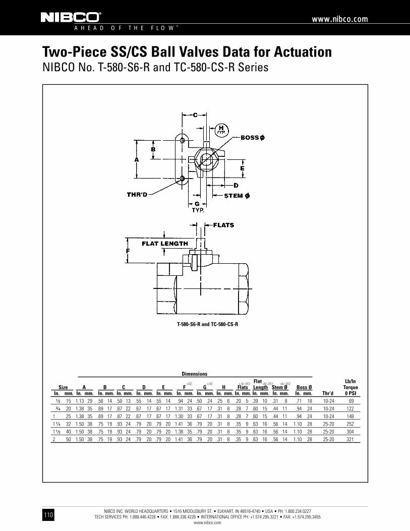
NIBCO INC. WORLD HEADQUARTERS • 1516 MIDDLEBURY ST. • ELKHART, IN 46516-4740 • USA • PH: 1.800.234.0227 TECH SERVICES PH: 1.888.446.4226 • FAX: 1.888.336.4226 • INTERNATIONAL OFFICE PH: +1.574.295.3221 • FAX: +1.574.295.3455
www.nibco.com
A H E A D O F T H E F L O W ™
wwwwww..nniibbccoo..ccoomm
110
Two-Piece SS/CS Ball Valves Data for ActuationNIBCO No. T-580-S6-R and TC-580-CS-R Series
DimensionsFlat Lb/In
Size A B C D E F G H Flats Length Stem Ø Boss Ø TorqueIn. mm. In. mm. In. mm. In. mm. In. mm. In. mm. In. mm. In. mm. In. mm. In. mm. In. mm. In. mm. In. mm. Thr‘d 0 PSI¹⁄₂ 15 1.13 29 .56 14 .50 13 .55 14 .55 14 .94 24 .50 24 .25 6 .20 5 .39 10 .31 8 .71 18 10-24 69³⁄₄ 20 1.38 35 .69 17 .87 22 .67 17 .67 17 1.31 33 .67 17 .31 8 .28 7 .60 15 .44 11 .94 24 10-24 122
1 25 1.38 35 .69 17 .87 22 .67 17 .67 17 1.30 33 .67 17 .31 8 .28 7 .60 15 .44 11 .94 24 10-24 1481 ¹⁄₄ 32 1.50 38 .75 19 .93 24 .79 20 .79 20 1.41 36 .79 20 .31 8 .35 9 .63 16 .56 14 1.10 28 25-20 2521 ¹⁄₂ 40 1.50 38 .75 19 .93 24 .79 20 .79 20 1.38 35 .79 20 .31 8 .35 9 .63 16 .56 14 1.10 28 25-20 3042 50 1.50 38 .75 19 .93 24 .79 20 .79 20 1.41 36 .79 20 .31 8 .35 9 .63 16 .56 14 1.10 28 25-20 321
+.02 +.02 + 0/-.012 +0/-.012 +0/-.012
T-580-S6-R and TC-580-CS-R
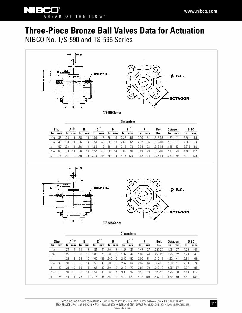
NIBCO INC. WORLD HEADQUARTERS • 1516 MIDDLEBURY ST. • ELKHART, IN 46516-4740 • USA • PH: 1.800.234.0227 TECH SERVICES PH: 1.888.446.4226 • FAX: 1.888.336.4226 • INTERNATIONAL OFFICE PH: +1.574.295.3221 • FAX: +1.574.295.3455
www.nibco.com
A H E A D O F T H E F L O W ™
wwwwww..nniibbccoo..ccoomm
111
Three-Piece Bronze Ball Valves Data for ActuationNIBCO No. T/S-590 and TS-595 Series
Dimensions
Size A B C D E F Bolt Octagon Ø BCIn. mm. In. mm. In. mm. In. mm. In. mm. In. mm. In. mm. Dia. In. mm. In. mm.
1 ¹⁄₄ 32 .25 6 .38 10 1.08 28 .36 9 2.32 59 2.00 51 .312-18 1.62 41 2.56 651 ¹⁄₂ 40 .38 10 .56 14 1.59 40 .50 13 2.62 67 2.62 66 .312-18 2.00 51 2.90 742 50 .38 10 .56 14 1.65 42 .50 13 3.12 79 2.84 72 .312-18 2.25 57 3.373 862 ¹⁄₂ 65 .38 10 .56 14 1.57 40 .56 14 3.88 99 3.13 79 .375-16 2.75 70 4.40 1123 75 .44 11 .75 19 2.18 55 .56 14 4.72 120 4.12 105 .437-14 3.50 89 5.47 139
+0 ± 03 + .03-.002
Dimensions
Size A B C D E F Bolt Octagon Ø BCIn. mm. In. mm. In. mm. In. mm. In. mm. In. mm. In. mm. Dia. In. mm. In. mm.¹⁄₂ .22 6 .31 8 .84 21 .30 8 1.38 35 1.47 37 .250-20 1.06 27 1.79 45³⁄₄ .25 6 .38 10 1.09 28 .38 10 1.87 47 1.82 46 .250-20 1.25 32 1.79 45
1 .25 6 .38 10 1.09 28 .369 9 2.32 59 2.00 51 .312-18 1.62 41 2.56 651 ¹⁄₂ 40 .38 10 .56 14 1.59 40 .50 13 2.62 67 2.62 66 .312-18 2.00 51 2.90 742 50 .38 10 .56 14 1.65 42 .50 13 3.12 79 2.84 72 .312-18 2.25 57 3.37 862 ¹⁄₂ 65 .38 10 .56 14 1.57 40 .56 14 3.88 99 3.13 79 .375-16 2.75 70 4.40 1123 75 .44 11 .75 19 2.18 55 .56 14 4.72 120 4.12 105 .437-14 3.50 89 5.47 139
+0 ± 03 + .03-.002
T/S-590 Series
T/S-595 Series
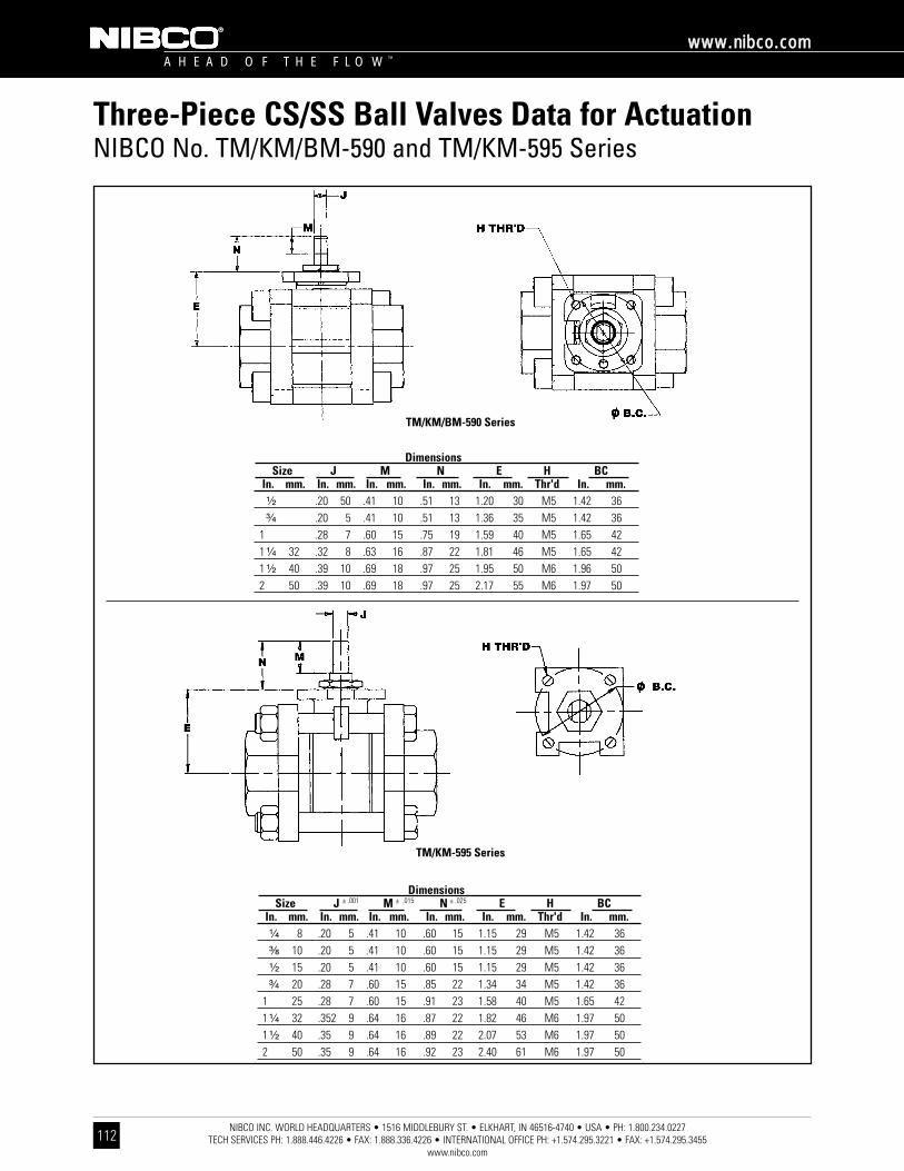
NIBCO INC. WORLD HEADQUARTERS • 1516 MIDDLEBURY ST. • ELKHART, IN 46516-4740 • USA • PH: 1.800.234.0227 TECH SERVICES PH: 1.888.446.4226 • FAX: 1.888.336.4226 • INTERNATIONAL OFFICE PH: +1.574.295.3221 • FAX: +1.574.295.3455
www.nibco.com
A H E A D O F T H E F L O W ™
wwwwww..nniibbccoo..ccoomm
112
Three-Piece CS/SS Ball Valves Data for ActuationNIBCO No. TM/KM/BM-590 and TM/KM-595 Series
DimensionsSize J M N E H BC
In. mm. In. mm. In. mm. In. mm. In. mm. Thr'd In. mm.¹⁄₂ .20 50 .41 10 .51 13 1.20 30 M5 1.42 36³⁄₄ .20 5 .41 10 .51 13 1.36 35 M5 1.42 36
1 .28 7 .60 15 .75 19 1.59 40 M5 1.65 421 ¹⁄₄ 32 .32 8 .63 16 .87 22 1.81 46 M5 1.65 421 ¹⁄₂ 40 .39 10 .69 18 .97 25 1.95 50 M6 1.96 502 50 .39 10 .69 18 .97 25 2.17 55 M6 1.97 50
DimensionsSize J M N E H BC
In. mm. In. mm. In. mm. In. mm. In. mm. Thr'd In. mm.¹⁄₄ 8 .20 5 .41 10 .60 15 1.15 29 M5 1.42 36³⁄₈ 10 .20 5 .41 10 .60 15 1.15 29 M5 1.42 36¹⁄₂ 15 .20 5 .41 10 .60 15 1.15 29 M5 1.42 36³⁄₄ 20 .28 7 .60 15 .85 22 1.34 34 M5 1.42 36
1 25 .28 7 .60 15 .91 23 1.58 40 M5 1.65 421 ¹⁄₄ 32 .352 9 .64 16 .87 22 1.82 46 M6 1.97 501 ¹⁄₂ 40 .35 9 .64 16 .89 22 2.07 53 M6 1.97 502 50 .35 9 .64 16 .92 23 2.40 61 M6 1.97 50
± .001 ± .015 ± .025
TM/KM/BM-590 Series
TM/KM-595 Series
NIBCO INC. WORLD HEADQUARTERS • 1516 MIDDLEBURY ST. • ELKHART, IN 46516-4740 • USA • PH: 1.800.234.0227 TECH SERVICES PH: 1.888.446.4226 • FAX: 1.888.336.4226 • INTERNATIONAL OFFICE PH: +1.574.295.3221 • FAX: +1.574.295.3455
www.nibco.com
A H E A D O F T H E F L O W ™
wwwwww..nniibbccoo..ccoomm
113
Engineering Data IndexFFllooww DDaattaa .. .. .. .. .. .. .. .. .. .. .. .. .. .. .. .. .. .. .. .. .. .. .. .. .. .. .. .. .. .. .. .. .. .. .. .. .. .. .. .. .. .. .. .. .. .. .. .. .. .. .. .. .. .. .. .. .. .. .. .. .. .. .. .. .. .. .. .. .. .. .. .. .. .. .. .. .. .. .. ..111144-111155
PPrrooppeerrttiieess ooff VVaallvvee MMaatteerriiaallss .. .. .. .. .. .. .. .. .. .. .. .. .. .. .. .. .. .. .. .. .. .. .. .. .. .. .. .. .. .. .. .. .. .. .. .. .. .. .. .. .. .. .. .. .. .. .. .. .. .. .. .. .. .. .. .. .. .. .. .. .. .. .. ..111166-111199Bronze, Brass, Copper and Iron . . . . . . . . . . . . . . . . . . . . . . . . . . . . . . . . . . . . . . . . . . . . . . . . . . . . . . . . . .116-117Steel, Stainless Steel and Alloys . . . . . . . . . . . . . . . . . . . . . . . . . . . . . . . . . . . . . . . . . . . . . . . . . . . . . . . . .118-119
SSppeecciiffiiccaattiioonnss .. .. .. .. .. .. .. .. .. .. .. .. .. .. .. .. .. .. .. .. .. .. .. .. .. .. .. .. .. .. .. .. .. .. .. .. .. .. .. .. .. .. .. .. .. .. .. .. .. .. .. .. .. .. .. .. .. .. .. .. .. .. .. .. .. .. .. .. .. .. .. .. .. .. .. .. .. .. .. ..112200
FFiigguurree NNuummbbeerr CCoommppaarriissoonn .. .. .. .. .. .. .. .. .. .. .. .. .. .. .. .. .. .. .. .. .. .. .. .. .. .. .. .. .. .. .. .. .. .. .. .. .. .. .. .. .. .. .. .. .. .. .. .. .. .. .. .. .. .. .. .. .. .. .. .. .. .. .. .. .. .. .. .. ..112211
VVaallvvee WWaarrrraannttyy .. .. .. .. .. .. .. .. .. .. .. .. .. .. .. .. .. .. .. .. .. .. .. .. .. .. .. .. .. .. .. .. .. .. .. .. .. .. .. .. .. .. .. .. .. .. .. .. .. .. .. .. .. .. .. .. .. .. .. .. .. .. .. .. .. .. .. .. .. .. .. .. .. .. .. .. .. .. ..112222
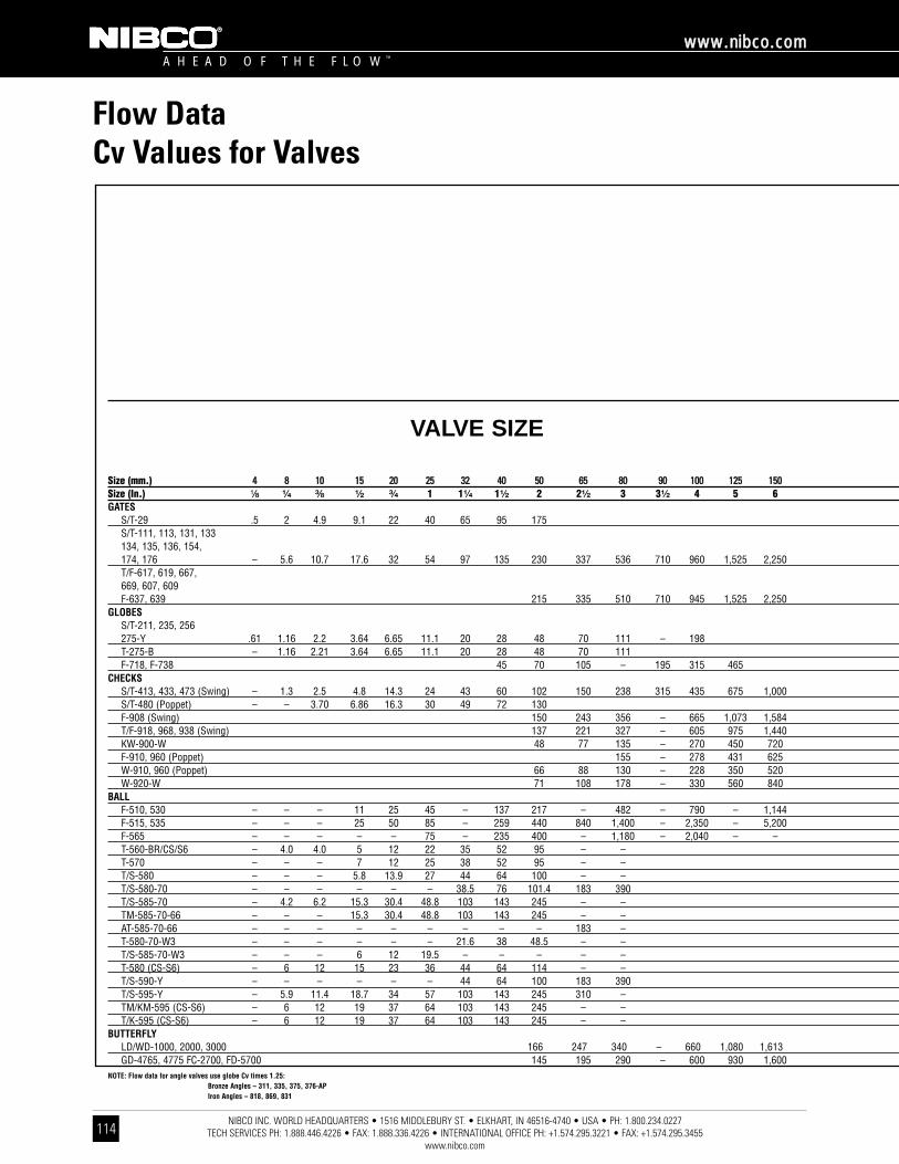
NIBCO INC. WORLD HEADQUARTERS • 1516 MIDDLEBURY ST. • ELKHART, IN 46516-4740 • USA • PH: 1.800.234.0227 TECH SERVICES PH: 1.888.446.4226 • FAX: 1.888.336.4226 • INTERNATIONAL OFFICE PH: +1.574.295.3221 • FAX: +1.574.295.3455
www.nibco.com
A H E A D O F T H E F L O W ™
wwwwww..nniibbccoo..ccoomm
114
Flow DataCv Values for Valves
Size (mm.) 44 88 1100 1155 2200 2255 3322 4400 5500 6655 8800 9900 110000 112255 115500Size (In.) ¹⁄₈ ¹⁄₄ ³⁄₈ ¹⁄₂ ³⁄₄ 1 1¹⁄₄ 1¹⁄₂ 2 2¹⁄₂ 3 3¹⁄₂ 4 5 6GATES
S/T-29 .5 2 4.9 9.1 22 40 65 95 175S/T-111, 113, 131, 133 134, 135, 136, 154, 174, 176 – 5.6 10.7 17.6 32 54 97 135 230 337 536 710 960 1,525 2,250T/F-617, 619, 667, 669, 607, 609 F-637, 639 215 335 510 710 945 1,525 2,250
GLOBESS/T-211, 235, 256275-Y .61 1.16 2.2 3.64 6.65 11.1 20 28 48 70 111 – 198T-275-B – 1.16 2.21 3.64 6.65 11.1 20 28 48 70 111F-718, F-738 45 70 105 – 195 315 465
CHECKSS/T-413, 433, 473 (Swing) – 1.3 2.5 4.8 14.3 24 43 60 102 150 238 315 435 675 1,000S/T-480 (Poppet) – – 3.70 6.86 16.3 30 49 72 130F-908 (Swing) 150 243 356 – 665 1,073 1,584T/F-918, 968, 938 (Swing) 137 221 327 – 605 975 1,440KW-900-W 48 77 135 – 270 450 720F-910, 960 (Poppet) 155 – 278 431 625W-910, 960 (Poppet) 66 88 130 – 228 350 520W-920-W 71 108 178 – 330 560 840
BALLF-510, 530 – – – 11 25 45 – 137 217 – 482 – 790 – 1,144F-515, 535 – – – 25 50 85 – 259 440 840 1,400 – 2,350 – 5,200F-565 – – – – – 75 – 235 400 – 1,180 – 2,040 – –T-560-BR/CS/S6 – 4.0 4.0 5 12 22 35 52 95 – –T-570 – – – 7 12 25 38 52 95 – –T/S-580 – – – 5.8 13.9 27 44 64 100 – –T/S-580-70 – – – – – – 38.5 76 101.4 183 390T/S-585-70 – 4.2 6.2 15.3 30.4 48.8 103 143 245 – –TM-585-70-66 – – – 15.3 30.4 48.8 103 143 245 – –AT-585-70-66 – – – – – – – – – 183 –T-580-70-W3 – – – – – – 21.6 38 48.5 – –T/S-585-70-W3 – – – 6 12 19.5 – – – – –T-580 (CS-S6) – 6 12 15 23 36 44 64 114 – –T/S-590-Y – – – – – – 44 64 100 183 390T/S-595-Y – 5.9 11.4 18.7 34 57 103 143 245 310 –TM/KM-595 (CS-S6) – 6 12 19 37 64 103 143 245 – –T/K-595 (CS-S6) – 6 12 19 37 64 103 143 245 – –
BUTTERFLYLD/WD-1000, 2000, 3000 166 247 340 – 660 1,080 1,613GD-4765, 4775 FC-2700, FD-5700 145 195 290 – 600 930 1,600
NOTE: Flow data for angle valves use globe Cv times 1.25:Bronze Angles – 311, 335, 375, 376-APIron Angles – 818, 869, 831
VALVE SIZE
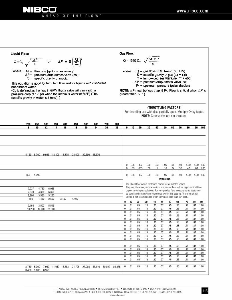
200 250 300 350 400 450 500 600 750 9008 10 12 14 16 18 20 24 30 36 0 10 20 30 40 50 60 70 80 90 100
4,150 6,700 9,925 13,800 18,375 23,600 29,600 43,570
0 .35 .65 .90 .93 .96 .98 .99 1.00 1.00 1.000 .03 .035 .06 .1 .16 .24 .32 .47 .68 1.00
860 1,390 0 .35 .65 .90 .93 .96 .98 .99 1.00 1.00 1.00
2,937 4,730 6,9852,670 4,300 6,3502,200 3,550 5,250500 1,450 2,500 3,400 4,400
2,164 3,507 5,51610,200 14,400 25,300
3,759 5,300 7,969 11,917 16,383 21,705 27,908 43,116 60,922 86,3753,450 5,800 8,950
NIBCO INC. WORLD HEADQUARTERS • 1516 MIDDLEBURY ST. • ELKHART, IN 46516-4740 • USA • PH: 1.800.234.0227 TECH SERVICES PH: 1.888.446.4226 • FAX: 1.888.336.4226 • INTERNATIONAL OFFICE PH: +1.219.295.3221 • FAX: +1.219.295.3455
www.nibco.com
A H E A D O F T H E F L O W ™
wwwwww..nniibbccoo..ccoomm
115
WARNING
The Fluid Flow factors contained herein are calculated values.They are, therefore, approximations and cannot be used for highly critical flowor pressure drop calculations. For very precise flow measurements, tests mustbe conducted on any valve mentioned within this catalog. Throttling of ballvalves is not recommended when valves are less than 45° open.
(THROTTLING FACTORS)For throttling use with disc partially open. Multiply Cv by factor.
NOTE: Gate valves are not throttled.
00 1100 2200 3300 4400 4455 5500 6600 7700 8800 99000 .01 .05 .16 .30 .37 .45 .58 .71 .87 1.000 .01 .05 .16 .30 .37 .45 .58 .71 .87 1.000 .01 .05 .16 .30 .37 .45 .58 .71 .87 1.000 .01 .05 .16 .30 .37 .45 .58 .71 .87 1.000 .01 .05 .16 .30 .37 .45 .58 .71 .87 1.000 .01 .05 .16 .30 .37 .45 .58 .71 .87 1.000 .01 .05 .16 .30 .37 .45 .58 .71 .87 1.000 .01 .05 .16 .30 .37 .45 .58 .71 .87 1.000 .01 .05 .16 .30 .37 .45 .58 .71 .87 1.000 .01 .05 .16 .30 .37 .45 .58 .71 .87 1.000 .01 .05 .16 .30 .37 .45 .58 .71 .87 1.00
0 .01 .05 .16 .30 .37 .45 .58 .71 .87 1.000 .01 .05 .16 .30 .37 .45 .58 .71 .87 1.000 .01 .05 .16 .30 .37 .45 .58 .71 .87 1.000 .01 .05 .16 .30 .37 .45 .58 .71 .87 1.000 .01 .05 .16 .30 .37 .45 .58 .71 .87 1.00
0 .01 .05 .16 .30 .37 .45 .58 .71 .87 1.00
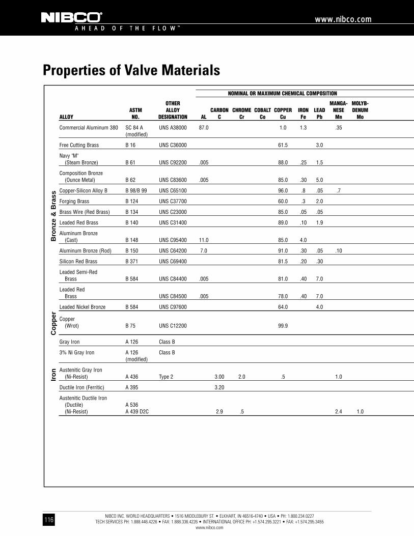
NIBCO INC. WORLD HEADQUARTERS • 1516 MIDDLEBURY ST. • ELKHART, IN 46516-4740 • USA • PH: 1.800.234.0227 TECH SERVICES PH: 1.888.446.4226 • FAX: 1.888.336.4226 • INTERNATIONAL OFFICE PH: +1.574.295.3221 • FAX: +1.574.295.3455
www.nibco.com
A H E A D O F T H E F L O W ™
wwwwww..nniibbccoo..ccoomm
116
A H E A D O F T H E F L O W ™
OTHER MANGA- MOLYB-ASTM ALLOY CARBON CHROME COBALT COPPER IRON LEAD NESE DENUM
ALLOY NO. DESIGNATION AL C Cr Co Cu Fe Pb Mn Mo
Commercial Aluminum 380 SC 84 A UNS A38000 87.0 1.0 1.3 .35(modified)
Free Cutting Brass B 16 UNS C36000 61.5 3.0
Navy "M"(Steam Bronze) B 61 UNS C92200 .005 88.0 .25 1.5
Composition Bronze(Ounce Metal) B 62 UNS C83600 .005 85.0 .30 5.0
Copper-Silicon Alloy B B 98/B 99 UNS C65100 96.0 .8 .05 .7
Forging Brass B 124 UNS C37700 60.0 .3 2.0
Brass Wire (Red Brass) B 134 UNS C23000 85.0 .05 .05
Leaded Red Brass B 140 UNS C31400 89.0 .10 1.9
Aluminum Bronze(Cast) B 148 UNS C95400 11.0 85.0 4.0
Aluminum Bronze (Rod) B 150 UNS C64200 7.0 91.0 .30 .05 .10
Silicon Red Brass B 371 UNS C69400 81.5 .20 .30
Leaded Semi-RedBrass B 584 UNS C84400 .005 81.0 .40 7.0
Leaded RedBrass UNS C84500 .005 78.0 .40 7.0
Leaded Nickel Bronze B 584 UNS C97600 64.0 4.0
Copper(Wrot) B 75 UNS C12200 99.9
Gray Iron A 126 Class B
3% Ni Gray Iron A 126 Class B(modified)
Austenitic Gray Iron(Ni-Resist) A 436 Type 2 3.00 2.0 .5 1.0
Ductile Iron (Ferritic) A 395 3.20
Austenitic Ductile Iron(Ductile) A 536(Ni-Resist) A 439 D2C 2.9 .5 2.4 1.0
Properties of Valve MaterialsNOMINAL OR MAXIMUM CHEMICAL COMPOSITION
Iro
nC
op
per
Bro
nze
& B
rass

NIBCO INC. WORLD HEADQUARTERS • 1516 MIDDLEBURY ST. • ELKHART, IN 46516-4740 • USA • PH: 1.800.234.0227 TECH SERVICES PH: 1.888.446.4226 • FAX: 1.888.336.4226 • INTERNATIONAL OFFICE PH: +1.574.295.3221 • FAX: +1.574.295.3455
www.nibco.com
A H E A D O F T H E F L O W ™
wwwwww..nniibbccoo..ccoomm
117
TITAN- TUNG- TENSILE YIELDNICKEL PHOS SILICON SULFUR TIN IUM STEN ZINC STRENGTH STRENGTH %
Ni P Si S Sn Ti W Zn Psi Psi ELONGATION HARDNESS
.50 12.0 .15 .50 42,000 19,000 3.5
35.5 50,000 20,000 15 75 HRB
65 HB1.0 .05 .005 .05 6.0 4.5 34,000 16,000 22 *500 kg
60 HB1.0 .05 .005 .08 5.0 5.0 30,000 14,000 20 500 kg
1.6 1.5 86,000** 20,000 11 65 HRB
38.0 52,000 20,000 45 80 HRB
15.0 56,000 60 HRB
.7 9.1 50,000 30,000 7 60 HRB
170 HB75,000 30,000 12 *3000 kg
.25 2.0 .20 .50 90,000 45,000 9 80 HRB
4.0 14.5 80,000 40,000 15 85 HRB
55 HB.02 .005 .08 3.0 9.0 29,000 13,000 18 *500 kg
55 HB1.0 .02 .005 .08 3.0 12.0 29,000 13,000 16 *500 kg
20.0 4.0 8.0 40,000 17,000 10 80 HB
.02 36,000 30,000 25 45 T
.75 .15 31,000 195 HB
3.00 .75 .15 31,000 195 HB
20.0 2.0 .12 25,000 118 HB
.08 2.50 60,000 40,000 18 167 HB
.08 2.50 80,000 55,000 6 160 HB24.0 .08 3.0 58,000 28,000 20 146 HB
*Load Applied During Testing**Allowable Range is 75,000 to 95,000
NOMINAL OR MAXIMUM CHEMICAL COMPOSITION NOMINAL PHYSICAL PROPERTIES
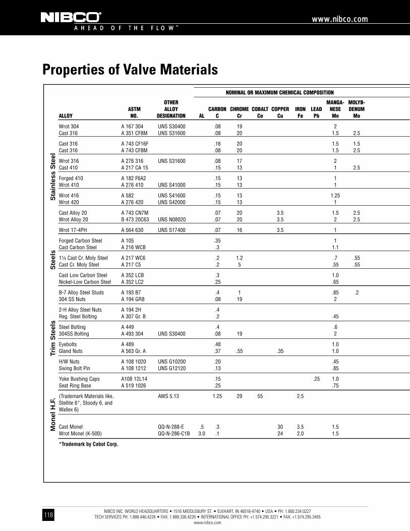
NIBCO INC. WORLD HEADQUARTERS • 1516 MIDDLEBURY ST. • ELKHART, IN 46516-4740 • USA • PH: 1.800.234.0227 TECH SERVICES PH: 1.888.446.4226 • FAX: 1.888.336.4226 • INTERNATIONAL OFFICE PH: +1.574.295.3221 • FAX: +1.574.295.3455
www.nibco.com
A H E A D O F T H E F L O W ™
wwwwww..nniibbccoo..ccoomm
118
A H E A D O F T H E F L O W ™
OTHER MANGA- MOLYB-ASTM ALLOY CARBON CHROME COBALT COPPER IRON LEAD NESE DENUM
ALLOY NO. DESIGNATION AL C Cr Co Cu Fe Pb Mn Mo
Wrot 304 A 167 304 UNS S30400 .08 19 2Cast 316 A 351 CF8M UNS S31600 .08 20 1.5 2.5
Cast 316 A 743 CF16F .16 20 1.5 1.5Cast 316 A 743 CF8M .08 20 1.5 2.5
Wrot 316 A 276 316 UNS S31600 .08 17 2Cast 410 A 217 CA 15 .15 13 1 2.5
Forged 410 A 182 F6A2 .15 13 1Wrot 410 A 276 410 UNS S41000 .15 13 1
Wrot 416 A 582 UNS S41600 .15 13 1.25Wrot 420 A 276 420 UNS S42000 .15 13 1
Cast Alloy 20 A 743 CN7M .07 20 3.5 1.5 2.5Wrot Alloy 20 B 473 20C63 UNS N08020 .07 20 3.5 2 2.5
Wrot 17-4PH A 564 630 UNS S17400 .07 16 3.5 1
Forged Carbon Steel A 105 .35 1Cast Carbon Steel A 216 WCB .3 1.1
1¹⁄₄ Cast Cr. Moly Steel A 217 WC6 .2 1.2 .7 .55Cast Cr. Moly Steel A 217 C5 .2 5 .55 .55
Cast Low Carbon Steel A 352 LCB .3 1.0Nickel-Low Carbon Steel A 352 LC2 .25 .65
B-7 Alloy Steel Studs A 193 B7 .4 1 .85 .2304 SS Nuts A 194 GR8 .08 19 2
2-H Alloy Steel Nuts A 194 2H .4Reg. Steel Bolting A 307 Gr. B .2 .45
Steel Bolting A 449 .4 .6304SS Bolting A 493 304 UNS S30400 .08 19 2
Eyebolts A 489 .48 1.0Gland Nuts A 563 Gr. A .37 .55 .35 1.0
H/W Nuts A 108 1020 UNS G10200 .20 .45Swing Bolt Pin A 108 1212 UNS G12120 .13 .85
Yoke Bushing Caps A108 12L14 .15 .25 1.0Seat Ring Base A 519 1026 .25 .75
(Trademark Materials like, AWS 5.13 1.25 29 55 2.5Stellite 6*, Stoody 6, andWallex 6)
Cast Monel QQ-N-288-E .5 .3 30 3.5 1.5Wrot Monel (K-500) QQ-N-286-C1B 3.0 .1 24 2.0 1.5
*Trademark by Cabot Corp.
Properties of Valve MaterialsNOMINAL OR MAXIMUM CHEMICAL COMPOSITION
Trim
Ste
els
Mo
nel
H.F
.S
teel
sS
tain
less
Ste
el

NIBCO INC. WORLD HEADQUARTERS • 1516 MIDDLEBURY ST. • ELKHART, IN 46516-4740 • USA • PH: 1.800.234.0227 TECH SERVICES PH: 1.888.446.4226 • FAX: 1.888.336.4226 • INTERNATIONAL OFFICE PH: +1.574.295.3221 • FAX: +1.574.295.3455
www.nibco.com
A H E A D O F T H E F L O W ™
wwwwww..nniibbccoo..ccoomm
119
TITAN- TUNG- TENSILE YIELDNICKEL PHOS SILICON SULFUR TIN IUM STEN ZINC STRENGTH STRENGTH %
Ni P Si S Sn Ti W Zn Psi Psi ELONGATION HARDNESS
9 .045 1.0 .03 75,000 30,000 40 202 HB11 .04 2.0 .04 70,000 30,000 25
11 .04 2.0 .04 70,000 30,000 3012 .045 1.0 .03 75,000 30,000 30
12 .045 1.0 .03 75,000 30,000 301 .04 1.5 .04 90,000 65,000 18
.04 1.0 .03 85,000 55,000 18 200/225 HB.5 .04 1.0 .03 100,000 80,000 15
.06 1.0 .15 114,000 95,000 17 235 HB
.04 1.0 .03 250/450 HB
28 .04 1.5 .04 62,000 25,000 3535 .045 1.0 .035 85,000 35,000 30
4 .04 1.0 .03 115,000 75,000 18 255 HB
.04 .035 .05 70,000 36,000 22 187 HB
.04 .6 .045 70,000 36,000 22
.04 .06 .045
.04 .75 .045
.04 .6 .045 65,000 35,000 242.5 .04 .6 .045 70,000 40,000 24
.035 .25 .04 125,000 105,000 169 .045 1.0 .03 126/300 HB
.04 .05 250/300 HB
.04 .05 100,000 18 121/212 HB
.04 .05 120,000 92,000 149 .045 1.0 .03 90,000
.04 .25 .05 75,000 30,000 30.35 .04 .2 .05
.04 .05 120/300 HB
.10 .20
.07 .3
.04 .05 55,000 35,000 25
3 5 105,000 10 350 HB
60 1.5 65,000 32,500 25 125/150 HB67 .5 .01 .5 135,000 95,000 20 255 HB
NOMINAL OR MAXIMUM CHEMICAL COMPOSITION NOMINAL PHYSICAL PROPERTIES
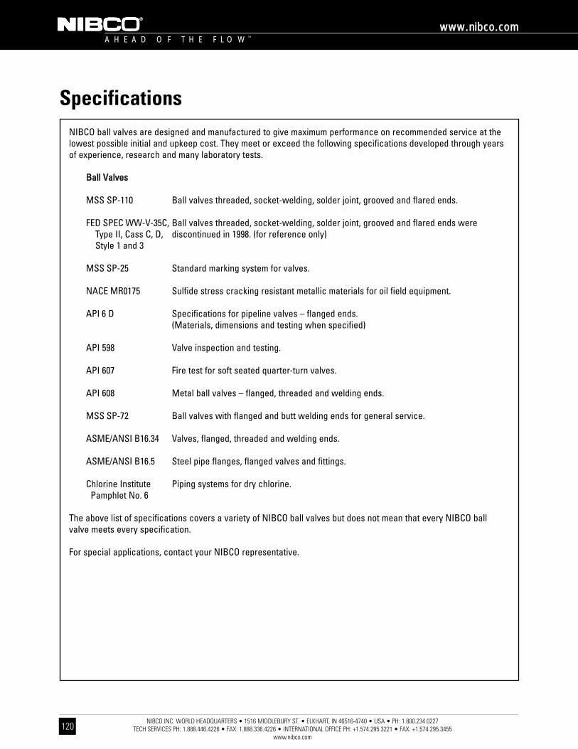
A H E A D O F T H E F L O W ™
wwwwww..nniibbccoo..ccoomm
NIBCO INC. WORLD HEADQUARTERS • 1516 MIDDLEBURY ST. • ELKHART, IN 46516-4740 • USA • PH: 1.800.234.0227 TECH SERVICES PH: 1.888.446.4226 • FAX: 1.888.336.4226 • INTERNATIONAL OFFICE PH: +1.574.295.3221 • FAX: +1.574.295.3455
www.nibco.com
Specifications
120
NIBCO ball valves are designed and manufactured to give maximum performance on recommended service at thelowest possible initial and upkeep cost. They meet or exceed the following specifications developed through yearsof experience, research and many laboratory tests.
BBaallll VVaallvveess
MSS SP-110 Ball valves threaded, socket-welding, solder joint, grooved and flared ends.
FED SPEC WW-V-35C, Ball valves threaded, socket-welding, solder joint, grooved and flared ends wereType II, Cass C, D, discontinued in 1998. (for reference only)Style 1 and 3
MSS SP-25 Standard marking system for valves.
NACE MR0175 Sulfide stress cracking resistant metallic materials for oil field equipment.
API 6 D Specifications for pipeline valves – flanged ends. (Materials, dimensions and testing when specified)
API 598 Valve inspection and testing.
API 607 Fire test for soft seated quarter-turn valves.
API 608 Metal ball valves – flanged, threaded and welding ends.
MSS SP-72 Ball valves with flanged and butt welding ends for general service.
ASME/ANSI B16.34 Valves, flanged, threaded and welding ends.
ASME/ANSI B16.5 Steel pipe flanges, flanged valves and fittings.
Chlorine Institute Piping systems for dry chlorine.Pamphlet No. 6
The above list of specifications covers a variety of NIBCO ball valves but does not mean that every NIBCO ball valve meets every specification.
For special applications, contact your NIBCO representative.
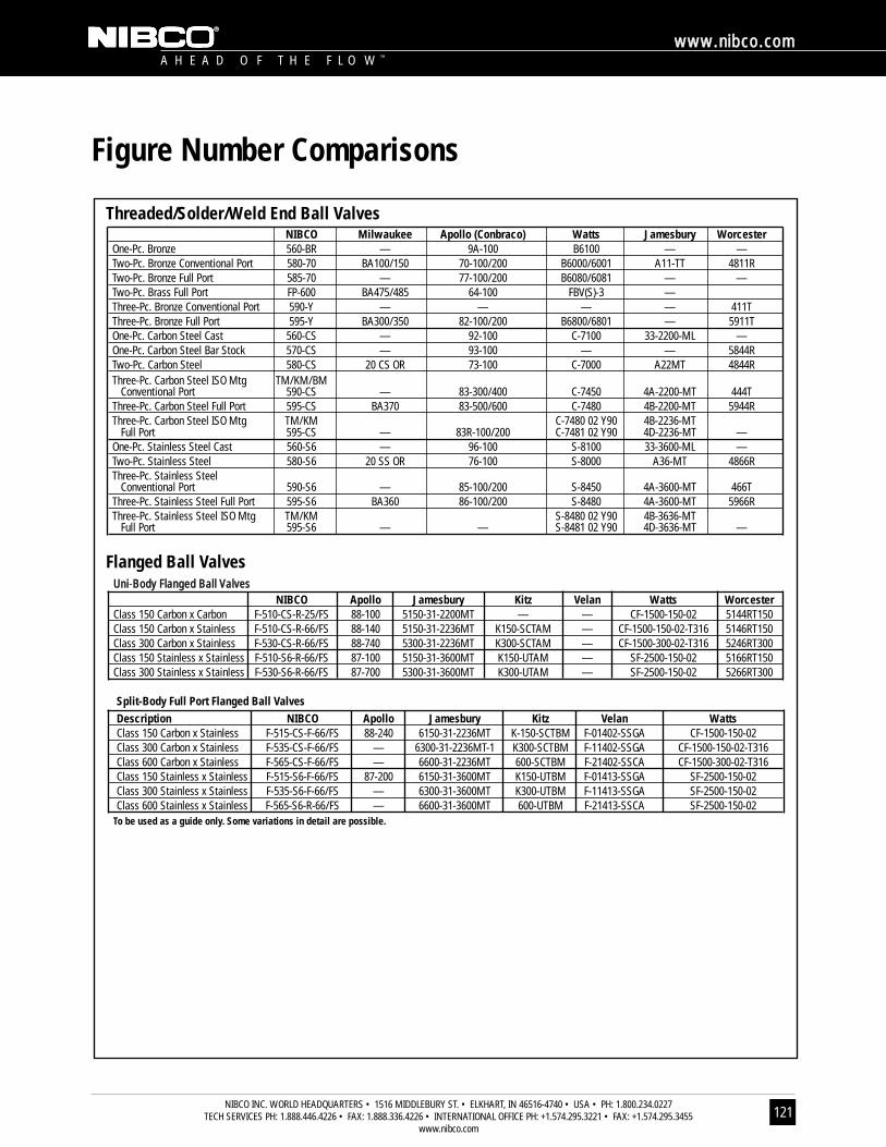
A H E A D O F T H E F L O W ™
wwwwww..nniibbccoo..ccoomm
NIBCO INC. WORLD HEADQUARTERS • 1516 MIDDLEBURY ST. • ELKHART, IN 46516-4740 • USA • PH: 1.800.234.0227 TECH SERVICES PH: 1.888.446.4226 • FAX: 1.888.336.4226 • INTERNATIONAL OFFICE PH: +1.574.295.3221 • FAX: +1.574.295.3455
www.nibco.com121
Figure Number Comparisons
NIBCO Milwaukee Apollo (Conbraco) Watts Jamesbury WorcesterOne-Pc. Bronze 560-BR — 9A-100 B6100 — —Two-Pc. Bronze Conventional Port 580-70 BA100/150 70-100/200 B6000/6001 A11-TT 4811RTwo-Pc. Bronze Full Port 585-70 — 77-100/200 B6080/6081 — —Two-Pc. Brass Full Port FP-600 BA475/485 64-100 FBV(S)-3 —Three-Pc. Bronze Conventional Port 590-Y — — — — 411TThree-Pc. Bronze Full Port 595-Y BA300/350 82-100/200 B6800/6801 — 5911TOne-Pc. Carbon Steel Cast 560-CS — 92-100 C-7100 33-2200-ML —One-Pc. Carbon Steel Bar Stock 570-CS — 93-100 — — 5844RTwo-Pc. Carbon Steel 580-CS 20 CS OR 73-100 C-7000 A22MT 4844RThree-Pc. Carbon Steel ISO Mtg TM/KM/BM
Conventional Port 590-CS — 83-300/400 C-7450 4A-2200-MT 444TThree-Pc. Carbon Steel Full Port 595-CS BA370 83-500/600 C-7480 4B-2200-MT 5944RThree-Pc. Carbon Steel ISO Mtg TM/KM C-7480 02 Y90 4B-2236-MT
Full Port 595-CS — 83R-100/200 C-7481 02 Y90 4D-2236-MT —One-Pc. Stainless Steel Cast 560-S6 — 96-100 S-8100 33-3600-ML —Two-Pc. Stainless Steel 580-S6 20 SS OR 76-100 S-8000 A36-MT 4866RThree-Pc. Stainless Steel
Conventional Port 590-S6 — 85-100/200 S-8450 4A-3600-MT 466TThree-Pc. Stainless Steel Full Port 595-S6 BA360 86-100/200 S-8480 4A-3600-MT 5966RThree-Pc. Stainless Steel ISO Mtg TM/KM S-8480 02 Y90 4B-3636-MT
Full Port 595-S6 — — S-8481 02 Y90 4D-3636-MT —
UUnnii-BBooddyy FFllaannggeedd BBaallll VVaallvveessNIBCO Apollo Jamesbury Kitz Velan Watts Worcester
Class 150 Carbon x Carbon F-510-CS-R-25/FS 88-100 5150-31-2200MT — — CF-1500-150-02 5144RT150Class 150 Carbon x Stainless F-510-CS-R-66/FS 88-140 5150-31-2236MT K150-SCTAM — CF-1500-150-02-T316 5146RT150Class 300 Carbon x Stainless F-530-CS-R-66/FS 88-740 5300-31-2236MT K300-SCTAM — CF-1500-300-02-T316 5246RT300Class 150 Stainless x Stainless F-510-S6-R-66/FS 87-100 5150-31-3600MT K150-UTAM — SF-2500-150-02 5166RT150Class 300 Stainless x Stainless F-530-S6-R-66/FS 87-700 5300-31-3600MT K300-UTAM — SF-2500-150-02 5266RT300
Split-Body Full Port Flanged Ball ValvesDescription NIBCO Apollo Jamesbury Kitz Velan WattsClass 150 Carbon x Stainless F-515-CS-F-66/FS 88-240 6150-31-2236MT K-150-SCTBM F-01402-SSGA CF-1500-150-02Class 300 Carbon x Stainless F-535-CS-F-66/FS — 6300-31-2236MT-1 K300-SCTBM F-11402-SSGA CF-1500-150-02-T316Class 600 Carbon x Stainless F-565-CS-F-66/FS — 6600-31-2236MT 600-SCTBM F-21402-SSCA CF-1500-300-02-T316Class 150 Stainless x Stainless F-515-S6-F-66/FS 87-200 6150-31-3600MT K150-UTBM F-01413-SSGA SF-2500-150-02Class 300 Stainless x Stainless F-535-S6-F-66/FS — 6300-31-3600MT K300-UTBM F-11413-SSGA SF-2500-150-02Class 600 Stainless x Stainless F-565-S6-R-66/FS — 6600-31-3600MT 600-UTBM F-21413-SSCA SF-2500-150-02
To be used as a guide only. Some variations in detail are possible.
Threaded/Solder/Weld End Ball Valves
Flanged Ball Valves
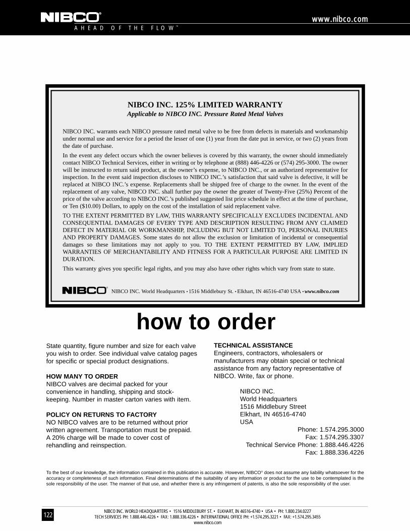
A H E A D O F T H E F L O W ™
wwwwww..nniibbccoo..ccoomm
NIBCO INC. WORLD HEADQUARTERS • 1516 MIDDLEBURY ST. • ELKHART, IN 46516-4740 • USA • PH: 1.800.234.0227 TECH SERVICES PH: 1.888.446.4226 • FAX: 1.888.336.4226 • INTERNATIONAL OFFICE PH: +1.574.295.3221 • FAX: +1.574.295.3455
www.nibco.com122
State quantity, figure number and size for each valveyou wish to order. See individual valve catalog pagesfor specific or special product designations.
HOW MANY TO ORDER NIBCO valves are decimal packed for yourconvenience in handling, shipping and stock-keeping. Number in master carton varies with item.
POLICY ON RETURNS TO FACTORYNO NIBCO valves are to be returned without priorwritten agreement. Transportation must be prepaid.A 20% charge will be made to cover cost ofrehandling and reinspection.
NIBCO INC. 125% LIMITED WARRANTYApplicable to NIBCO INC. Pressure Rated Metal Valves
NIBCO INC. warrants each NIBCO pressure rated metal valve to be free from defects in materials and workmanshipunder normal use and service for a period the lesser of one (1) year from the date put in service, or two (2) years fromthe date of purchase.
In the event any defect occurs which the owner believes is covered by this warranty, the owner should immediatelycontact NIBCO Technical Services, either in writing or by telephone at (888) 446-4226 or (574) 295-3000. The ownerwill be instructed to return said product, at the owner’s expense, to NIBCO INC., or an authorized representative forinspection. In the event said inspection discloses to NIBCO INC.’s satisfaction that said valve is defective, it will bereplaced at NIBCO INC.’s expense. Replacements shall be shipped free of charge to the owner. In the event of thereplacement of any valve, NIBCO INC. shall further pay the owner the greater of Twenty-Five (25%) Percent of theprice of the valve according to NIBCO INC.’s published suggested list price schedule in effect at the time of purchase,or Ten ($10.00) Dollars, to apply on the cost of the installation of said replacement valve.
TO THE EXTENT PERMITTED BY LAW, THIS WARRANTY SPECIFICALLY EXCLUDES INCIDENTAL ANDCONSEQUENTIAL DAMAGES OF EVERY TYPE AND DESCRIPTION RESULTING FROM ANY CLAIMEDDEFECT IN MATERIAL OR WORKMANSHIP, INCLUDING BUT NOT LIMITED TO, PERSONAL INJURIESAND PROPERTY DAMAGES. Some states do not allow the exclusion or limitation of incidental or consequentialdamages so these limitations may not apply to you. TO THE EXTENT PERMITTED BY LAW, IMPLIEDWARRANTIES OF MERCHANTABILITY AND FITNESS FOR A PARTICULAR PURPOSE ARE LIMITED INDURATION.
This warranty gives you specific legal rights, and you may also have other rights which vary from state to state.
NIBCO INC. World Headquarters • 1516 Middlebury St. • Elkhart, IN 46516-4740 USA • www.nibco.com
TECHNICAL ASSISTANCE Engineers, contractors, wholesalers ormanufacturers may obtain special or technicalassistance from any factory representative ofNIBCO. Write, fax or phone.
NIBCO INC.World Headquarters1516 Middlebury StreetElkhart, IN 46516-4740USA
Phone: 1.574.295.3000Fax: 1.574.295.3307
Technical Service Phone: 1.888.446.4226 Fax: 1.888.336.4226
To the best of our knowledge, the information contained in this publication is accurate. However, NIBCO® does not assume any liability whatsoever for theaccuracy or completeness of such information. Final determinations of the suitability of any information or product for the use to be contemplated is thesole responsibility of the user. The manner of that use, and whether there is any infringement of patents, is also the sole responsibility of the user.
how to order
NIBCO INC. WORLD HEADQUARTERS • 1516 MIDDLEBURY ST. • ELKHART, IN 46516-4740 • USA • PH: 1.800.234.0227 TECH SERVICES PH:1.888.446.4226 • FAX: 1.888.336.4226 • INTERNATIONAL OFFICE PH: +1.574.295.3221 • FAX: +1.574.295.3455
www.nibco.com
WorldHeadquarters
Elkhart,Indiana
Metal Valves and Fittings
Blytheville, Arkansas
McAllen, Texas
Nacogdoches, Texas
South GlensFalls, New York
Stuarts Draft, Virginia
Plastic Pipe, Valves, and Fittings
Greensboro,Georgia
Goshen,Indiana
Denmark, South Carolina
Industrial Plastics
Charlestown, Indiana
International
Lodz, Poland
Reynosa, Mexico
U.S. & InternationalDistribution Centers
Atlanta, Georgia
Charlestown,Indiana
Columbus, Ohio
Elkhart, Indiana
Lodz, Poland
Los Angeles,California
Global Offices
Elkhart, Indiana
Hong Kong, China
Lodz, Poland
Monterrey, Mexico
Aurora, OntarioCanada (Rep.)
M A N U F A C T U R I N G D I S T R I B U T I O N I N T E R N AT I O N A L
It’s a new age of
business, and a new way
at NIBCO. From Elkhart,
Indiana to Lodz, Poland,
and points beyond, our
company has integrated
manufacturing, distribution, and
networked communications to
provide a seamless source of infor-
mation and service, 24 hours a day,
7 days a week. But this integration
hasn’t happened overnight. It’s
been part of a long-term strategic
process that has pushed us to
reconsider every aspect of our
business. The result? We’re a
vertically integrated manufacturer
with the products and systems in
place to deliver low cost and high
quality. NIBCO’s products are
manufactured under a Quality
Management System conforming
to the current revision of ISO-9002
International Standards. We know
the flow control industry is only
going to get more demanding, and
we are more than ready. We will
continue to lead. That’s what
NIBCO is all about.
globally connecting you at all levels

C-BV-1201 © 2001, N IBCO INC. P r i n t ed i n USA
N I B C O I N C .
W O R L D H E A D Q U A R T E R S
W E B : w w w . n i b c o . c o m
1 5 1 6 M I D D L E B U R Y S T R E E T
E L K H A R T, I N 4 6 5 1 6 - 4 7 4 0
U S A
D O M E S T I C C U S T O M E R S E R V I C E
P H O N E : 8 0 0 . 2 3 4 . 0 2 2 7
F A X : 8 0 0 . 2 3 4 . 0 5 5 7
T E C H N I C A L S E R V I C E
P H O N E : 8 8 8 . 4 4 6 . 4 2 2 6
F A X : 8 8 8 . 3 3 6 . 4 2 2 6
I N T E R N A T I O N A L S E R V I C E
P H O N E : + 1 / 5 7 4 . 2 9 5 . 3 2 2 1
F A X : + 1 / 5 7 4 . 2 9 5 . 3 4 5 5
F I T T I N G S
VALVES & ACTUATION
CHEMTROL®
eNIBCOA suite of services designed to make customers more efficient • More cost-effective• More informed • EDI—Electronic Data Interchange • VMI—Vendor ManagedInventory • NIBCO.com • NIBCOpartner.com • eNIBCO will continuously develop new products to deliver the competitive advantage.
Pressure-rated bronze, iron and alloy-iron gate, globe and check valves • Pressure-rated bronze ball valves • Boiler specialty valves • Commercial and industrial butterfly valves • Circuit balancing valves • Carbon and stainless steel ball valves •ANSI flanged steel ball valves • Pneumatic and electric actuators and controls • Grooved ball and butterfly valves • UL/FM fire protection valves • Low-pressuregate, globe, check and ball valves • Bronze specialty valves • Frostproof sillcocks• MSS specification valves • PVC ball valves • CPVC CTS ball valves.
Thermoplastic pipe, valves and fittings in PVC, Corzan® CPVC, polypropyleneand PVDF Kynar® • Chem-Aire® thermoplastic compressed air piping systems• Pneumatic and electric actuation systems.
Wrot and cast copper pressure fittings • Wrot and cast copper drainage fittings • Wrot copper PEXlink® fittings • Cast copper alloy flared fittings • Castcopper alloy flanges • ABS and PVC DWV fittings • Schedule 40 PVC pressurefittings • CPVC CTS fittings • CPVC CTS-to-metal transition fittings • Schedule 80PVC and CPVC systems • CPVC metric piping systems.
Corzan® is a registered trademark of Noveon, Inc. Kynar® is a registered trademark of ATOFINA Chemicals, Inc.
CC-BBVV-11220011