Ball Lens Based Common Path Fiber Optic Interferometer Sensor · fiber patch cord (LC type) ......
4
Volume 6 • Issue 3 • 1000178 J Biosens Bioelectron ISSN: 2155-6210 JBSBE, an open access journal Research Article Open Access Eom, J Biosens Bioelectron 2015, 6:3 DOI: 10.4172/2155-6210.1000178 *Corresponding author: Joo Beom Eom, Medical Photonic Research Center, Korea Photonics Technology Institute, 9 Cheomdan venture-ro 108 beon-gil, Buk-gu, Gwangju, 500-779, South Korea, Tel: +82626059114; E-mail: [email protected] Received July 25, 2015; Accepted August 14, 2015; Published September 01, 2015 Citation: Eom JB (2015) Ball Lens Based Common Path Fiber Optic Interferometer Sensor. J Biosens Bioelectron 6: 178. doi:10.4172/2155-6210.1000178 Copyright: © 2015 Eom JB. This is an open-access article distributed under the terms of the Creative Commons Attribution License, which permits unrestricted use, distribution, and reproduction in any medium, provided the original author and source are credited. Keywords: Fiber optic sensor; Common path optical probe; Interferometer; Ball lens Introduction e refractive index (RI) is one of the important properties of a substance such as biological tissues, thin film, and liquids [1-3]. In bio- sensing there is a need to measure small RI changes in small volumes of liquid. Traditional bulk refractometers are then not appropriate because of their size and weight. Fiber optic sensor is widely used for compactness, cost-effectiveness, flexibility, and multiplexing capability [4,5]. Espcially, at measurement of RI, the interferometric techniques use the interference between a sample beam and reference beam. e interferometric techniques obtain refractive index by measuring the change in the optical path difference (OPD) induced by the sample. But, optical fiber length mismatch between sample and reference beams might lead to a dispersion mismatch in fibers that can reduce sensitivity, if not corrected numerically [6]. Besides, the signal polarization states in the fibers need to be controlled to avoid polarization mismatch which can also reduce sensitivity [7]. In order to solve these problems, common path interferometer have been studied that the reference signal is generated at same path of the sample are fiber. Common path probe cleaved at 0 degrees for front viewing [8], and angled polished for side viewing [9] have been used as lensless common path probe. However, fiber type interferometer generally have short cavity length and is easily broken with small deformation. eir packaging for practical usages is not simple also. Furthermore, these reflective methods using fiber optic cannot be used for the liguid whose RI exceeds the fiber core index [5]. In this paper, we report the implementation of the sensing probe that can satisfy long working distance, massroduction, and reproducibility to be a sensing probe for measurement of refractive index. In order to satisfy these conditions, a dielectric mirror and a ball lens are simply placed in front of a conventional lucent connector (LC) type fiber patch cord with a specially designed package. Here, the design and the fabrication process of the proposed sensing probe are presented in detail. Further, with the proposed sensing probe, a new scheme of common path interferometer is implemented. By presenting RI measurement of the liquids, index matching oil, and glucose solution, we confirm the operation of the proposed common path sensing probe. Fabrication of Ball Lens Based Common Path Interferometer Figure 1 shows the scheme and pictures of the proposed common path interferometer based on lensed patch cord. Lensed patch cord consists of ball lens and LC type fiber patch cord. We fabricated a ball lens which was designed for efficient coupling of LC type connector. Ball lens was anti-reflection coated in order to remove the reflection at surfaces of ball lens and was packaged in a metal cylinder in order to block contamination and connect easily with fiber ferrule. Lensed patch cord is simply implemented by inserting the ferrule of a conventional fiber patch cord (LC type) into the hole of a metal packaged ball lens. Due to its simple geometry, no alinment problem is expected. Above all, the metal cylinder packaged ball lens is easily detachable and replaceable so that it allows to be disposable. Adjusting the gap between the fiber patch cord and the ball lens, with a 1.5 mm ball lens, diameter gave a proper working distance of a lensed patch cord probe. Aſter that, lensed patch cord was connected with dielectric mirror which was fabricated with transparent material to observe condition of liquid. Figure 1c is ball lens based common path probe which consists of ball lens, dielectric mirror and LC type fiber patch cord. e working distance of lensed patch cord was measured by monitoring the optical power variation of the beam reflected back from a mirror place in front of the probe, which was moved in step of 2 μm. 1500 measurements were taken by using an optical power meter, an optical circulator, and DFB LD with 1310 nm center wavelength. As shown in Figure 2a, the working distance of the probe with the gap length of 1.4 mm between fiber end face and ball lens was measured as long as 1.6 mm. As shown in Figure 2b, the spot size at the focal plane of the probe was measured with the displacement of a sharp edge [10]. e transverse resolution of the probe was measured as 4 μm. shown in Figure 2b. Further, the reflection property of the dielectric mirror was shown in Figure 3. As shown in Figure 1a, the interference is formed between the beam reflected at the end face of fiber patch cord E R (z) and the beam reflected at the mirror Es(z+∆z), where ∆z is the optical path length difference (OPD) between the end face of the fiber patch cord and mirror. e interference in the spectral domain can be written as [11]. ( ) ( ) ( ) ( ) ( ) 2 2 2 * R S R S R S I k E k E k exp ik z E E E E exp ik z c.c = + ∆ = + + ∆ + (1) Ball Lens Based Common Path Fiber Optic Interferometer Sensor Joo Beom Eom* Medical Photonic Research Center, Korea Photonics Technology Institute, South Korea Abstract A common path interferometer has been made with a ball lens packaged in a metal cylinder, dielectric mirror, and lucent type connector (LC) fiber patch cord. By simply placing metal cylinder packaged mirror and a ball lens directly in front of a fiber patch cord, a compact and potentially disposable sensing probe for optical bio-sensor could be implemented. To achieve a sufficiently long working distance, the proper ball lens diameter and the distance between the ball lens and the fiber patch cord were investigated. A working distance of up to 1.6 mm was achieved. With common path sensing probe, measurements of the index matching oil and glucose solutions were implemented and used to demonstrate the fesibility as the liquid sensing probe. Journal of Biosensors & Bioelectronics J o u r n a l o f B i o s e n s s o r & B i o e l e c t r o n i c s ISSN: 2155-6210
Transcript of Ball Lens Based Common Path Fiber Optic Interferometer Sensor · fiber patch cord (LC type) ......
Volume 6 • Issue 3 • 1000178J Biosens BioelectronISSN: 2155-6210 JBSBE, an open access journal
Research Article Open Access
Eom, J Biosens Bioelectron 2015, 6:3 DOI: 10.4172/2155-6210.1000178
*Corresponding author: Joo Beom Eom, Medical Photonic Research Center,Korea Photonics Technology Institute, 9 Cheomdan venture-ro 108 beon-gil, Buk-gu,Gwangju, 500-779, South Korea, Tel: +82626059114; E-mail: [email protected]
Received July 25, 2015; Accepted August 14, 2015; Published September 01, 2015
Citation: Eom JB (2015) Ball Lens Based Common Path Fiber Optic Interferometer Sensor. J Biosens Bioelectron 6: 178. doi:10.4172/2155-6210.1000178
Copyright: © 2015 Eom JB. This is an open-access article distributed under the terms of the Creative Commons Attribution License, which permits unrestricted use, distribution, and reproduction in any medium, provided the original author and source are credited.
Keywords: Fiber optic sensor; Common path optical probe;Interferometer; Ball lens
IntroductionThe refractive index (RI) is one of the important properties of a
substance such as biological tissues, thin film, and liquids [1-3]. In bio-sensing there is a need to measure small RI changes in small volumes of liquid. Traditional bulk refractometers are then not appropriate because of their size and weight. Fiber optic sensor is widely used for compactness, cost-effectiveness, flexibility, and multiplexing capability [4,5]. Espcially, at measurement of RI, the interferometric techniques use the interference between a sample beam and reference beam. The interferometric techniques obtain refractive index by measuring the change in the optical path difference (OPD) induced by the sample. But, optical fiber length mismatch between sample and reference beams might lead to a dispersion mismatch in fibers that can reduce sensitivity, if not corrected numerically [6]. Besides, the signal polarization states in the fibers need to be controlled to avoid polarization mismatch which can also reduce sensitivity [7]. In order to solve these problems, common path interferometer have been studied that the reference signal is generated at same path of the sample are fiber. Common path probe cleaved at 0 degrees for front viewing [8], and angled polished for side viewing [9] have been used as lensless common path probe. However, fiber type interferometer generally have short cavity length and is easily broken with small deformation. Their packaging for practical usages is not simple also. Furthermore, these reflective methods using fiber optic cannot be used for the liguid whose RI exceeds the fiber core index [5]. In this paper, we report the implementation of the sensing probe that can satisfy long working distance, massroduction, and reproducibility to be a sensing probe for measurement of refractive index. In order to satisfy these conditions, a dielectric mirror and a ball lens are simply placed in front of a conventional lucent connector (LC) type fiber patch cord with a specially designed package. Here, the design and the fabrication process of the proposed sensing probe are presented in detail. Further, with the proposed sensing probe, a new scheme of common path interferometer is implemented. By presenting RI measurement of the liquids, index matching oil, and glucose solution, we confirm the operation of the proposed common path sensing probe.
Fabrication of Ball Lens Based Common Path Interferometer
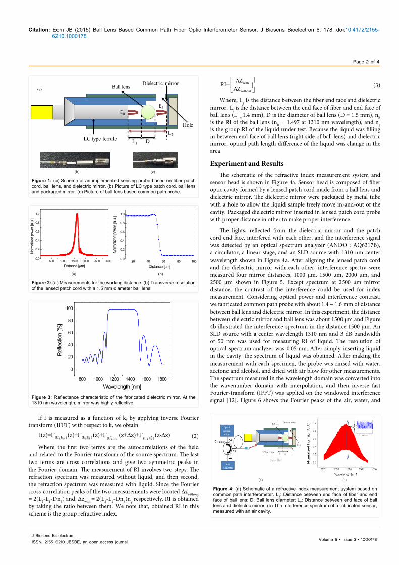
Figure 1 shows the scheme and pictures of the proposed common path interferometer based on lensed patch cord. Lensed patch cord consists of ball lens and LC type fiber patch cord. We fabricated a ball
lens which was designed for efficient coupling of LC type connector. Ball lens was anti-reflection coated in order to remove the reflection at surfaces of ball lens and was packaged in a metal cylinder in order to block contamination and connect easily with fiber ferrule. Lensed patch cord is simply implemented by inserting the ferrule of a conventional fiber patch cord (LC type) into the hole of a metal packaged ball lens. Due to its simple geometry, no alinment problem is expected. Above all, the metal cylinder packaged ball lens is easily detachable and replaceable so that it allows to be disposable. Adjusting the gap between the fiber patch cord and the ball lens, with a 1.5 mm ball lens, diameter gave a proper working distance of a lensed patch cord probe. After that, lensed patch cord was connected with dielectric mirror which was fabricated with transparent material to observe condition of liquid. Figure 1c is ball lens based common path probe which consists of ball lens, dielectric mirror and LC type fiber patch cord. The working distance of lensed patch cord was measured by monitoring the optical power variation of the beam reflected back from a mirror place in front of the probe, which was moved in step of 2 μm. 1500 measurements were taken by using an optical power meter, an optical circulator, and DFB LD with 1310 nm center wavelength. As shown in Figure 2a, the working distance of the probe with the gap length of 1.4 mm between fiber end face and ball lens was measured as long as 1.6 mm. As shown in Figure 2b, the spot size at the focal plane of the probe was measured with the displacement of a sharp edge [10]. The transverse resolution of the probe was measured as 4 μm. shown in Figure 2b. Further, the reflection property of the dielectric mirror was shown in Figure 3. As shown in Figure 1a, the interference is formed between the beam reflected at the end face of fiber patch cord ER(z) and the beam reflected at the mirror Es(z+∆z), where ∆z is the optical path length difference (OPD) between the end face of the fiber patch cord and mirror. The interference in the spectral domain can be written as [11].
( ) ( ) ( ) ( ) ( )2 2 2 *R S R S R SI k E k E k exp ik z E E E E exp ik z c.c = + ∆ = + + ∆ + (1)
Ball Lens Based Common Path Fiber Optic Interferometer SensorJoo Beom Eom*Medical Photonic Research Center, Korea Photonics Technology Institute, South Korea
AbstractA common path interferometer has been made with a ball lens packaged in a metal cylinder, dielectric mirror,
and lucent type connector (LC) fiber patch cord. By simply placing metal cylinder packaged mirror and a ball lens directly in front of a fiber patch cord, a compact and potentially disposable sensing probe for optical bio-sensor could be implemented. To achieve a sufficiently long working distance, the proper ball lens diameter and the distance between the ball lens and the fiber patch cord were investigated. A working distance of up to 1.6 mm was achieved. With common path sensing probe, measurements of the index matching oil and glucose solutions were implemented and used to demonstrate the fesibility as the liquid sensing probe.
Journal of Biosensors & BioelectronicsJo
urna
l of B
iosens sor &Bioelectronics
ISSN: 2155-6210
Citation: Eom JB (2015) Ball Lens Based Common Path Fiber Optic Interferometer Sensor. J Biosens Bioelectron 6: 178. doi:10.4172/2155-6210.1000178
Page 2 of 4
Volume 6 • Issue 3 • 1000178J Biosens BioelectronISSN: 2155-6210 JBSBE, an open access journal
If I is measured as a function of k, by applying inverse Fourier transform (IFFT) with respect to k, we obtain
* *R R S S R S R S(E E ) (E E ) (E E ) (E E )
I(z)= (z)+ (z)+ (z+ z)+ (z- z)Γ Γ Γ ∆ Γ ∆ (2)
Where the first two terms are the autocorrelations of the field and related to the Fourier transform of the source spectrum. The last two terms are cross correlations and give two symmetric peaks in the Fourier domain. The measurement of RI involves two steps. The refraction spectrum was measured without liquid, and then second, the refraction spectrum was measured with liquid. Since the Fourier cross-correlation peaks of the two measurements were located ∆zwithout = 2(L2-L1-DnB) and, ∆zwith = 2(L2-L1-DnB)ng respectively. RI is obtained by taking the ratio between them. We note that, obtained RI in this scheme is the group refractive index.
with
without
ÄZRI=ÄZ
(3)
Where, L2 is the distance between the fiber end face and dielectric mirror, L1 is the distance between the end face of fiber and end face of ball lens (L1 = 1.4 mm), D is the diameter of ball lens (D = 1.5 mm), nB is the RI of the ball lens (nB = 1.497 at 1310 nm wavelength), and ng is the group RI of the liquid under test. Because the liquid was filling in between end face of ball lens (right side of ball lens) and dielectric mirror, optical path length difference of the liquid was change in the area
Experiment and Results The schematic of the refractive index measurement system and
sensor head is shown in Figure 4a. Sensor head is composed of fiber optic cavity formed by a lensed patch cord made from a ball lens and dielectric mirror. The dielectric mirror were packaged by metal tube with a hole to allow the liquid sample freely move in-and-out of the cavity. Packaged dielectric mirror inserted in lensed patch cord probe with proper distance in other to make proper interference.
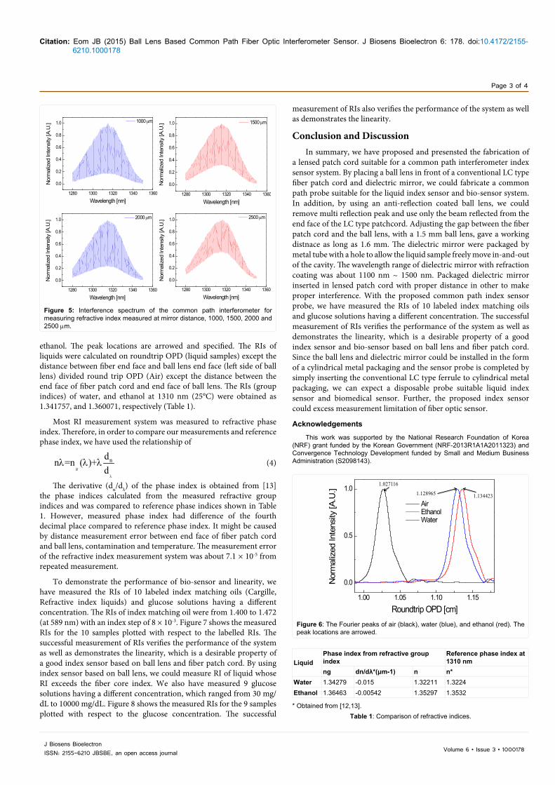
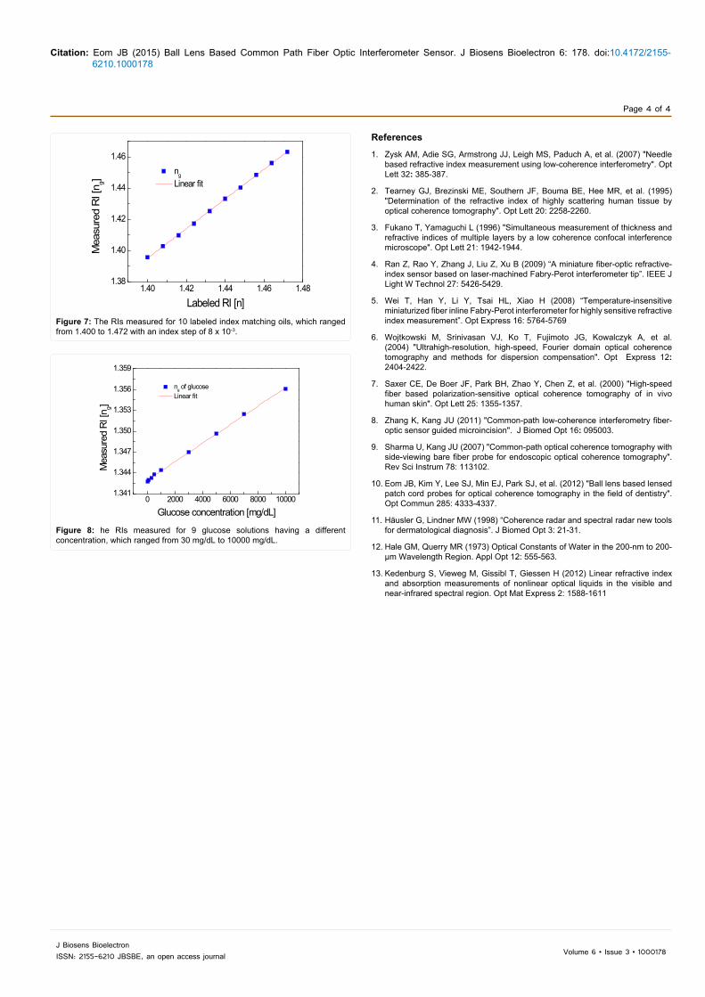
The lights, reflected from the dielectric mirror and the patch cord end face, interfered with each other, and the interference signal was detected by an optical spectrum analyzer (ANDO : AQ6317B), a circulator, a linear stage, and an SLD source with 1310 nm center wavelength shown in Figure 4a. After aligning the lensed patch cord and the dielectric mirror with each other, interference spectra were measured four mirror distances, 1000 μm, 1500 μm, 2000 μm, and 2500 μm shown in Figure 5. Except spectrum at 2500 μm mirror distance, the contrast of the interference could be used for index measurement. Considering optical power and interference contrast, we fabricated common path probe with about 1.4 ~ 1.6 mm of distance between ball lens and dielectric mirror. In this experiment, the distance between dielectric mirror and ball lens was about 1500 μm and Figure 4b illustrated the interference spectrum in the distance 1500 μm. An SLD source with a center wavelength 1310 nm and 3 dB bandwidth of 50 nm was used for measuring RI of liquid. The resolution of optical spectrum analyzer was 0.05 nm. After simply inserting liquid in the cavity, the spectrum of liquid was obtained. After making the measurement with each specimen, the probe was rinsed with water, acetone and alcohol, and dried with air blow for other measurements. The spectrum measured in the wavelength domain was converted into the wavenumber domain with interpolation, and then inverse fast Fourier-transform (IFFT) was applied on the windowed interference signal [12]. Figure 6 shows the Fourier peaks of the air, water, and
(a)
(b) (c)
Ball lens
LC type ferrule
Dielectric mirror
HoleL2
L1 D
ER
ES
Figure 1: (a) Scheme of an implemented sensing probe based on fiber patch cord, ball lens, and dielectric mirror. (b) Picture of LC type patch cord, ball lens and packaged mirror. (c) Picture of ball lens based common path probe.
0 500 1000 1500 2000 2500 30000.0
0.2
0.4
0.6
0.8
1.0
Norm
alize
d po
wer [
a.u.
]
Distance [µm]
(a) (b)
20 40 60 80 1000.0
0.2
0.4
0.6
0.8
1.0
Norm
alize
d po
wer [
a.u.
]
Distance [µm]
Figure 2: (a) Measurements for the working distance. (b) Transverse resolution of the lensed patch cord with a 1.5 mm diameter ball lens.
800 1000 1200 1400 1600 1800
0
20
40
60
80
100
Ref
lect
ion
[%]
Wavelength [nm]
Figure 3: Reflectance characteristic of the fabricated dielectric mirror. At the 1310 nm wavelength, mirror was highly reflective.
Figure 4: (a) Schematic of a refractive index measurement system based on common path interferometer. L1: Distance between end face of fiber and end face of ball lens; D: Ball lens diameter; L2: Distance between end face of ball lens and dielectric mirror. (b) The interference spectrum of a fabricated sensor, measured with an air cavity.
Citation: Eom JB (2015) Ball Lens Based Common Path Fiber Optic Interferometer Sensor. J Biosens Bioelectron 6: 178. doi:10.4172/2155-6210.1000178
Page 3 of 4
Volume 6 • Issue 3 • 1000178J Biosens BioelectronISSN: 2155-6210 JBSBE, an open access journal
ethanol. The peak locations are arrowed and specified. The RIs of liquids were calculated on roundtrip OPD (liquid samples) except the distance between fiber end face and ball lens end face (left side of ball lens) divided round trip OPD (Air) except the distance between the end face of fiber patch cord and end face of ball lens. The RIs (group indices) of water, and ethanol at 1310 nm (25°C) were obtained as 1.341757, and 1.360071, respectively (Table 1).
Most RI measurement system was measured to refractive phase index. Therefore, in order to compare our measurements and reference phase index, we have used the relationship of
g
ndn =n ( )+d
λ
λ λ λ (4)
The derivative (dn/dλ) of the phase index is obtained from [13] the phase indices calculated from the measured refractive group indices and was compared to reference phase indices shown in Table 1. However, measured phase index had difference of the fourth decimal place compared to reference phase index. It might be caused by distance measurement error between end face of fiber patch cord and ball lens, contamination and temperature. The measurement error of the refractive index measurement system was about 7.1 × 10⁻⁵ from repeated measurement.
To demonstrate the performance of bio-sensor and linearity, we have measured the RIs of 10 labeled index matching oils (Cargille, Refractive index liquids) and glucose solutions having a different concentration. The RIs of index matching oil were from 1.400 to 1.472 (at 589 nm) with an index step of 8 × 10⁻³. Figure 7 shows the measured RIs for the 10 samples plotted with respect to the labelled RIs. The successful measurement of RIs verifies the performance of the system as well as demonstrates the linearity, which is a desirable property of a good index sensor based on ball lens and fiber patch cord. By using index sensor based on ball lens, we could measure RI of liquid whose RI exceeds the fiber core index. We also have measured 9 glucose solutions having a different concentration, which ranged from 30 mg/dL to 10000 mg/dL. Figure 8 shows the measured RIs for the 9 samples plotted with respect to the glucose concentration. The successful
1280 1300 1320 1340 1360
0.0
0.2
0.4
0.6
0.8
1.0
Nor
mal
ized
Inte
nsity
[A.U
.]
Wavelength [nm]
1000 µm
1280 1300 1320 1340 1360
0.0
0.2
0.4
0.6
0.8
1.0
Nor
mal
ized
Inte
nsity
[A.U
.]
Wavelength [nm]
1500 µm
1280 1300 1320 1340 1360
0.0
0.2
0.4
0.6
0.8
1.0
Nor
mal
ized
Inte
nsity
[A.U
.]
Wavelength [nm]
2000 µm
1280 1300 1320 1340 1360
0.0
0.2
0.4
0.6
0.8
1.0
Nor
mal
ized
Inte
nsity
[A.U
.]
Wavelength [nm]
2500 µm
Figure 5: Interference spectrum of the common path interferometer for measuring refractive index measured at mirror distance, 1000, 1500, 2000 and 2500 µm.
1.027116
1.128965 1.134423
1.00 1.05 1.10 1.15
0.0
0.5
1.0
Nor
mal
ized
Inte
nsity
[A.U
.]
Roundtrip OPD [cm]
Air Ethanol Water
Figure 6: The Fourier peaks of air (black), water (blue), and ethanol (red). The peak locations are arrowed.
measurement of RIs also verifies the performance of the system as well as demonstrates the linearity.
Conclusion and Discussion In summary, we have proposed and presensted the fabrication of
a lensed patch cord suitable for a common path interferometer index sensor system. By placing a ball lens in front of a conventional LC type fiber patch cord and dielectric mirror, we could fabricate a common path probe suitable for the liquid index sensor and bio-sensor system. In addition, by using an anti-reflection coated ball lens, we could remove multi reflection peak and use only the beam reflected from the end face of the LC type patchcord. Adjusting the gap between the fiber patch cord and the ball lens, with a 1.5 mm ball lens, gave a working distnace as long as 1.6 mm. The dielectric mirror were packaged by metal tube with a hole to allow the liquid sample freely move in-and-out of the cavity. The wavelength range of dielectric mirror with refraction coating was about 1100 nm ~ 1500 nm. Packaged dielectric mirror inserted in lensed patch cord with proper distance in other to make proper interference. With the proposed common path index sensor probe, we have measured the RIs of 10 labeled index matching oils and glucose solutions having a different concentration. The successful measurement of RIs verifies the performance of the system as well as demonstrates the linearity, which is a desirable property of a good index sensor and bio-sensor based on ball lens and fiber patch cord. Since the ball lens and dielectric mirror could be installed in the form of a cylindrical metal packaging and the sensor probe is completed by simply inserting the conventional LC type ferrule to cylindrical metal packaging, we can expect a disposable probe suitable liquid index sensor and biomedical sensor. Further, the proposed index sensor could excess measurement limitation of fiber optic sensor.
Acknowledgements
This work was supported by the National Research Foundation of Korea (NRF) grant funded by the Korean Government (NRF-2013R1A1A2011323) and Convergence Technology Development funded by Small and Medium Business Administration (S2098143).
LiquidPhase index from refractive group index
Reference phase index at 1310 nm
ng dn/dλ*(μm-1) n n*Water 1.34279 -0.015 1.32211 1.3224Ethanol 1.36463 -0.00542 1.35297 1.3532
* Obtained from [12,13].Table 1: Comparison of refractive indices.
Citation: Eom JB (2015) Ball Lens Based Common Path Fiber Optic Interferometer Sensor. J Biosens Bioelectron 6: 178. doi:10.4172/2155-6210.1000178
Page 4 of 4
Volume 6 • Issue 3 • 1000178J Biosens BioelectronISSN: 2155-6210 JBSBE, an open access journal
1.40 1.42 1.44 1.46 1.481.38
1.40
1.42
1.44
1.46
Mea
sure
d R
I [n g]
Labeled RI [n]
ng
Linear fit
Figure 7: The RIs measured for 10 labeled index matching oils, which ranged from 1.400 to 1.472 with an index step of 8 x 10⁻³.
0 2000 4000 6000 8000 100001.341
1.344
1.347
1.350
1.353
1.356
1.359
ng of glucose Linear fit
Mea
sure
d RI
[ng]
Glucose concentration [mg/dL]
Figure 8: he RIs measured for 9 glucose solutions having a different concentration, which ranged from 30 mg/dL to 10000 mg/dL.
References
1. Zysk AM, Adie SG, Armstrong JJ, Leigh MS, Paduch A, et al. (2007) "Needlebased refractive index measurement using low-coherence interferometry". Opt Lett 32: 385-387.
2. Tearney GJ, Brezinski ME, Southern JF, Bouma BE, Hee MR, et al. (1995)"Determination of the refractive index of highly scattering human tissue byoptical coherence tomography". Opt Lett 20: 2258-2260.
3. Fukano T, Yamaguchi L (1996) "Simultaneous measurement of thickness andrefractive indices of multiple layers by a low coherence confocal interferencemicroscope". Opt Lett 21: 1942-1944.
4. Ran Z, Rao Y, Zhang J, Liu Z, Xu B (2009) “A miniature fiber-optic refractive-index sensor based on laser-machined Fabry-Perot interferometer tip”. IEEE JLight W Technol 27: 5426-5429.
5. Wei T, Han Y, Li Y, Tsai HL, Xiao H (2008) “Temperature-insensitiveminiaturized fiber inline Fabry-Perot interferometer for highly sensitive refractive index measurement”. Opt Express 16: 5764-5769
6. Wojtkowski M, Srinivasan VJ, Ko T, Fujimoto JG, Kowalczyk A, et al.(2004) "Ultrahigh-resolution, high-speed, Fourier domain optical coherencetomography and methods for dispersion compensation". Opt Express 12: 2404-2422.
7. Saxer CE, De Boer JF, Park BH, Zhao Y, Chen Z, et al. (2000) "High-speedfiber based polarization-sensitive optical coherence tomography of in vivo human skin". Opt Lett 25: 1355-1357.
8. Zhang K, Kang JU (2011) "Common-path low-coherence interferometry fiber-optic sensor guided microincision". J Biomed Opt 16: 095003.
9. Sharma U, Kang JU (2007) "Common-path optical coherence tomography with side-viewing bare fiber probe for endoscopic optical coherence tomography". Rev Sci Instrum 78: 113102.
10. Eom JB, Kim Y, Lee SJ, Min EJ, Park SJ, et al. (2012) "Ball lens based lensed patch cord probes for optical coherence tomography in the field of dentistry". Opt Commun 285: 4333-4337.
11. Häusler G, Lindner MW (1998) “Coherence radar and spectral radar new tools for dermatological diagnosis”. J Biomed Opt 3: 21-31.
12. Hale GM, Querry MR (1973) Optical Constants of Water in the 200-nm to 200-µm Wavelength Region. Appl Opt 12: 555-563.
13. Kedenburg S, Vieweg M, Gissibl T, Giessen H (2012) Linear refractive indexand absorption measurements of nonlinear optical liquids in the visible andnear-infrared spectral region. Opt Mat Express 2: 1588-1611