Ball Bearing Demountable Bushings
22
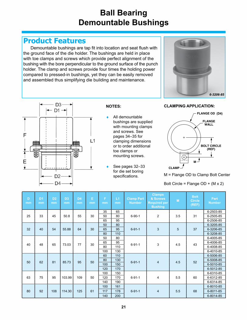
21 Ball Bearing Demountable Bushings Demountable bushings are tap fit into location and seat flush with the ground face of the die holder. The bushings are held in place with toe clamps and screws which provide perfect alignment of the bushing with the bore perpendicular to the ground surface of the punch holder. The clamp and screws provide four times the holding power compared to pressed-in bushings, yet they can be easily removed and assembled thus simplifying die building and maintenance. Product Features 6-3206-85 NOTES: ♦ All demountable bushings are supplied with mounting clamps and screws. See pages 34–35 for clamping dimensions or to order additional toe clamps or mounting screws. ♦ See pages 32–33 for die set boring specifications. D mm D1 mm D2 mm D3 mm D4 mm E mm F mm L1 mm Clamp Part Number Clamps & Screws Required per Bushing M Bolt Circle (REF) Part Number 25 33 45 50.8 55 30 35 65 6-90-1 2 3.5 31 6-2503-85 50 80 6-2505-85 65 95 6-2506-85 32 40 54 55.88 64 30 50 80 6-91-1 3 5 37 6-3205-85 65 95 6-3206-85 80 110 6-3208-85 40 48 65 73.03 77 30 50 80 6-91-1 3 4.5 43 6-4005-85 65 95 6-4006-85 80 110 6-4008-85 100 130 6-4010-85 50 62 81 85.73 95 50 60 110 6-91-1 4 4.5 52 6-5006-85 80 130 6-5008-85 100 150 6-5010-85 120 170 6-5012-85 63 75 95 103.99 109 50 100 150 6-91-1 4 5.5 60 6-6310-85 120 170 6-6312-85 140 190 6-6314-85 100 161 6-91-1 4 5.5 68 6-8010-85 80 92 108 114.30 125 61 117 178 6-8011-85 140 200 6-8014-85 FLANGE OD FLANGE WALL BOLT CIRCLE (REF) M CLAMP CLAMPING APPLICATION: M = Flange OD to Clamp Bolt Center Bolt Circle = Flange OD + (M x 2) (D4)
Transcript of Ball Bearing Demountable Bushings
21
Ball BearingDemountable Bushings
Demountable bushings are tap fit into location and seat flush with the ground face of the die holder. The bushings are held in place with toe clamps and screws which provide perfect alignment of the bushing with the bore perpendicular to the ground surface of the punch holder. The clamp and screws provide four times the holding power compared to pressed-in bushings, yet they can be easily removed and assembled thus simplifying die building and maintenance.
Product Features
6-3206-85
NOTES:
♦ All demountable bushings are supplied with mounting clamps and screws. See pages 34–35 for clamping dimensions or to order additional toe clamps or mounting screws.
♦ See pages 32–33 for die set boring specifications.
Dmm
D1 mm
D2 mm
D3mm
D4mm
E mm
F mm
L1 mm
Clamp Part Number
Clamps & Screws
Required per Bushing
MBolt
Circle (REF)
PartNumber
25 33 45 50.8 55 3035 65
6-90-1 2 3.5 316-2503-85
50 80 6-2505-8565 95 6-2506-85
32 40 54 55.88 64 3050 80
6-91-1 3 5 376-3205-85
65 95 6-3206-8580 110 6-3208-85
40 48 65 73.03 77 30
50 80
6-91-1 3 4.5 43
6-4005-8565 95 6-4006-8580 110 6-4008-85100 130 6-4010-85
50 62 81 85.73 95 50
60 110
6-91-1 4 4.5 52
6-5006-8580 130 6-5008-85100 150 6-5010-85120 170 6-5012-85
63 75 95 103.99 109 50100 150
6-91-1 4 5.5 606-6310-85
120 170 6-6312-85140 190 6-6314-85100 161
6-91-1 4 5.5 686-8010-85
80 92 108 114.30 125 61 117 178 6-8011-85140 200 6-8014-85
FLANGE OD
FLANGEWALL
BOLT CIRCLE(REF)
M
CLAMP
CLAMPING APPLICATION:
M = Flange OD to Clamp Bolt Center
Bolt Circle = Flange OD + (M x 2)
(D4)

22
Ball Bearing Straight Sleeve Bushings
Press fit bushings are manufactured from high quality hardened steel, the bushings are finish ground for a press fit. Like all ball bearing components, these straight sleeve bushings are completely inter-changeable.
Product Features
6-3209-86
INSTALLATION INSTRUCTIONS
In order to avoid the bushing close-in which occurs as a result of press-fit, these bushings should be retained with a Bushing Mount. When so installed, it is not necessary to hone the bushing bore after installation, and the bushing fit will be correct.
APPLICATION OF THE BUSHING MOUNT1. Degrease bushing OD and die shoe bore with alcohol, acetone or other volatile solvent and wipe dry.2. Apply Bushing Mount sparingly and wring bushing into die shoe.3. Allow a 4-hour cure at 72° F (23° C). Do not disturb bushing until cure is complete.
Bushing Mount Part number: 9-60-82
PostDiameter
mm
D1 mm
D2mm
L2mm
Part Number
25 33 45
65 6-2506-8680 6-2508-8695 6-2509-86110 6-2511-86130 6-2513-86
32 40 54
80 6-3208-8695 6-3209-86110 6-3211-86130 6-3213-86150 6-3215-86170 6-3217-86
40 48 65
80 6-4008-8695 6-4009-86110 6-4011-86130 6-4013-86150 6-4015-86170 6-4017-86190 6-4019-86215 6-4021-86
PostDiameter
mm
D1 mm
D2mm
L2mm
Part Number
50 62 81
110 6-5011-86130 6-5013-86150 6-5015-86170 6-5017-86190 6-5019-86215 6-5021-86240 6-5024-86265 6-5026-86
63 75 95
150 6-6315-86170 6-6317-86190 6-6319-86215 6-6321-86240 6-6324-86265 6-6326-86
80 92 112
150 6-8015-86170 6-8017-86190 6-8019-86215 6-8021-86240 6-8024-86265 6-8026-86

23
Demountable Ball Bearing Stripper Bushings and Cages
Product Features
6-2505-83 & 6-2525-87
Cage Data
Bushing Data
NOTES:
♦All demountable bushings are supplied with mounting clamps and screws. See pages 34–35 for clamping dimensions or to order additional toe clamps or mounting screws.
♦See pages 32–33 for die set boring specifications.
Type III cages are made using the same material and control standards as our Type I & II cages. Type III cages use an external snap ring to act as a cage carrier and stop. This allows the cage to rotate freely around the guide post when not under preload and prevents the cage from pushing through the guide bushing at full stroke. Ball bearings are arranged in a spiral pattern in the cage to minimize tracking or grooving and assure uniform wear. Low profile demountable bushings give maximum flexibility in die set design. The low profile bushing, coupled with low mount clamping, provide maximum available die set use. The bushings are manufactured from hardened steel and are designed for use with Type III cage components. These demountable bushings are a tap fit into location and seat flush with the ground face of the die holder. The bushings are held in place with low mount clamps and screws which provide perfect alignment of the bushing with the bore perpendicular to the ground surface of the die holder.
D mm
Lmm
Gmm
D2 mm
PartNumber
25 40 1.6 32.3 6-2504-8352 6-2505-83
32 40 1.9 39.3 6-3204-8352 6-3205-83
40 52 1.9 47.3 6-4005-8364 6-4006-83
50 74 2.2 61.2 6-5007-8388 6-5008-83
PostDiameter
mm
D1mm
D2mm
D4mm
E mm
Lmm
Clamp Part
Number
Clamps & Screws Req. per Bushing
MBolt
Circle (REF)
PartNumber
25 33 45 51 20 30 6-96-1 3 8 33.5 6-2520-8725 35 6-2525-87
32 40 54 6020 30
6-96-1 3 8 386-3220-87
25 35 6-3225-8732 42 6-3232-87
40 48 65 7529 39
6-97-1 4 8.5 466-4029-87
36 46 6-4036-8744 54 6-4044-87
50 62 81 91 36 46 6-97-1 4 8.5 54 6-5036-8744 54 6-5044-87
FLANGE OD
FLANGEWALL
BOLT CIRCLE(REF)
M
CLAMP
CLAMPING APPLICATION:
M = Flange OD to Clamp Bolt Center
Bolt Circle = Flange OD + (M x 2)
(D4)

24
Mounting Accessories
BUSHING MOUNT/RETAINING COMPOUND
BALL CAGE WASHER ASSEMBLy
NOTES:
♦ A bushing mount/retaining compound is used when installing straight sleeve ball bearing bushings to avoid bushing close-in as a result of press-fit.
Part Number Volume 9-60-82 118 mL
Guide Post Tap Sizes Required Seating Torque Diameter O mm Tap Size N-m In-lbs 25 – 32 M6 x 1.0 36 320 40 – 50 M10 x 1.5 98 867 63 – 80 M10 x 1.5 236 2088
NOTES:
♦ TyPE I Assembly includes stopwasher retainer and head hex screw.
♦ TyPE II Assembly includes stopwasher retainer, bushing stopwasher, hex head screw and snap ring.
BALL BEARING BUSHING LUBRICATION RECOMMENDATION
During the operation of the Ball Bearing Bushing Assembly, add lubricant once each 8-hour shift by spray or brush application. Use a refined mineral oil of viscosity 290/340 SSU @ 100° F (38° C) containing “EP” additives and rust inhibitors.
BALL CAGE WASHER ASSEMBLy
Snap Ring- Nominal Washer Assembly Bushing Hex Head Ball Bearing Post Part Number Stop Washer-Retainer Stop Washer Screw Cages Diameter Type I Type II Type Type Type Type Type A mm Assembly Assembly I II and III II and III I, II and III II and III 25 6-0025-81 6-0025-82 6-2500-85 6-2500-83 5-0800-840 9-0506-730 6-2500-86 32 6-0032-81 6-0032-82 6-3200-85 6-3200-83 6-3200-86 40 6-0040-81 6-0040-82 6-4000-85 6-4000-83 5-1200-840 9-0607-730 6-4000-86 50 6-0050-81 6-0050-82 6-5000-85 6-5000-83 6-5000-86 63 6-0063-81 6-0063-82 6-6300-85 6-6300-83 6-6300-86 80 6-0080-81 6-0080-82 6-8000-85 6-8000-83 5-2400-840 9-0808-730 6-8000-86
6-2500-84
6-4000-84
6-0620-933M6 x 20 DIN933
8G or 10K
6-1025-933M10 x 25 DIN933
8G or 10K
25
Ball Bearing ComponentsSelection Guide
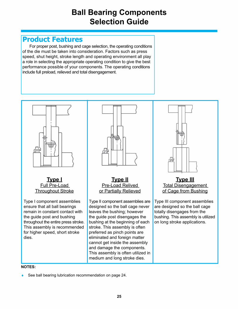
Type I Full Pre-Load
Throughout Stroke
Type I component assemblies ensure that all ball bearings remain in constant contact with the guide post and bushing throughout the entire press stroke. This assembly is recommended for higher speed, short stroke dies.
Type II Pre-Load Relived
or Partially Relieved
Type II component assemblies are designed so the ball cage never leaves the bushing; however the guide post disengages the bushing at the beginning of each stroke. This assembly is often preferred as pinch points are eliminated and foreign matter cannot get inside the assembly and damage the components. This assembly is often utilized in medium and long stroke dies.
Type III Total Disengagement of Cage from Bushing
Type III component assemblies are designed so the ball cage totally disengages from the bushing. This assembly is utilized on long stroke applications.
Product Features For proper post, bushing and cage selection, the operating conditions of the die must be taken into consideration. Factors such as press speed, shut height, stroke length and operating environment all play a role in selecting the appropriate operating condition to give the best performance possible of your components. The operating conditions include full preload, relieved and total disengagement.
NOTES:
♦ See ball bearing lubrication recommendation on page 24.

26
Type I Component Selection Guide
PRESS FIT POSTS 1. Calculate L, the desired guide post length, using one of the following 2 formulas: Assembly with Straight Sleeve Bushings: L=T-U1-Z Assembly with Demountable Bushings: L=T-U1-Z-J+E2. Select a post length from the catalog that is equal to L calculated above. If the calculated L value is not a
standard catalog length, you have two options. Choose the next longest length and cut off to the calculated L dimension or select a shorter length and recess the post in the punch holder to obtain correct L dimension.
Note: Press fit length should be equal to or greater than the diameter of the guide post.
DEMOUNTABLE POSTS 1. Calculate F1, the desired guide post length, using one of the following 2 formulas: Assembly with Straight Sleeve Bushings: F1=T-U1-Z-K (Note F+J+K+Y<T) Assembly with Demountable Bushing: F1=T-U1-Z-J+E-K (Note L2+K+Y<T)2. Select a post length from the catalog that is equal to F1 calculated above. If the calculated F1 value is not a
standard catalog length, choose a catalog length that is close to but less than the calculated F1. Note: Demountable posts cannot be cut off. See page 4 for standard post lengths (F1).
BUSHING & CAGE SELECTIONSelection of a Type 1 Ball bearing bushing and cage assembly
is based on the required stroke and the guide post diameter.1. Determine the guide post diameter required and the stroke required.2. Using the selection chart on page 27, find the desired stroke. Move down this column to the colored square
on the horizontal line opposite the required post diameter. 3. Select the required bushing length which is listed to the left of the selected square in the columns labeled
demountable shoulder and straight sleeve. Note: For applications with no off-center loading, select the bushing with the shortest overall length from the
selection chart. However for longer stroke applications or where side-loading may be present select the bush-ing with the longest possible length to provide optimal guidance.
4. Select the required cage length which is also listed to the left of the selected square in the column labeled “Ball Cage.”
Note: Shut height permitting, select the longest cage length possible for optimal performance.
NOTES:♦ If die grind is not required, stroke may be increased by
the amount of die grind allowance, dimension X, found in the right most column of the selection chart.
♦ A die set designed for a particular stroke may be used in any press of lesser stroke but never in any press where the stroke is greater than originally chosen.
♦ Die shoe thickness must be greater than “E” dimension when shoulder bushings are selected.
Post Diam. Z E U1 D mm mm mm mm 25 7 30 32 7 30 40 9.5 30 50 9.5 50 63 9.5 50 80 9.5 50
3

27
Type I Component Selection Guide
NOM. POST DIA.
BALL BUSHING BALL CAGE STROKE “S” INCLUDING DIE GRIND ALLOWANCE
*MAXIMUM DIE WEAR
ALLOWANCESHOULDER SLEEVE
Dmm
Fmm
L1mm
L2mm
Cmm
Xmm
25
35 65 65
36
48
10
50 80 80
65 95 95
- - 110
- - 130
32
50 80 80
36
48
10
65 95 95
80 110 110
- - 130
- - 150
- - 170
40
50 80 80
48
60
10
65 95 95
80 110 110
100 130 130
- - 150
- - 170
- - 190
- - 215
50
60 110 110
70
84
10
80 130 130
100 150 150
120 170 170
- - 190
- - 215
- - 240
- - 265
63
100 150 150
98 15
120 170 170
140 190 190
- - 215
- - 240
- - 265
80
- - 150
98 15
- - 170
- - 190
- - 215
- - 240
- - 265
20 40 60 80 100 120 140 160
If your selection falls in a white square, use Type II or Type III.

28
Type II & III Component Selection Guide
D Z E U1 U2 y mm mm mm mm mm mm 25 10.5 30 3.5 14.7 32 10.5 30 3.5 18.9 40 13 30 4 18.9 50 13 50 4 18.9 63 13 50 4 18.9 80 13 50 4 18.9
1.5

29
Type II & III Component Selection Guide
PRESS FIT POSTS 1. Calculate L, the desired guide post length, using one of the following 2 formulas: Assembly with Straight Sleeve Bushings: L=T-U2-Z Assembly with Demountable Bushings: L=T-U2-Z-J+E2. Select a post length from the catalog that is equal to L calculated above. If the calculated L value is not a standard catalog length, you have two options. Choose the next longest length and cut off to the calculated L dimension or select a shorter length and recess the post in the punch holder to obtain correct L dimension. Note: Press fit length should be equal to or greater than the diameter of the guide post.
DEMOUNTABLE POSTS 1. Calculate F1, the desired guide post length, using one of the following 2 formulas: Assembly with Straight Sleeve Bushings: F1=T-U2-Z-K (Note F+J+K+Y<T) Assembly with Demountable Bushings: F1=T-U1-Z-J+E-K (Note L2+K+Y<T)2. Select a post length from the catalog that is equal to F1 calculated above. If the calculated F1 value is not a standard catalog length, choose a catalog length that is close to but less than the calculated F1. Note: Demountable posts cannot be cut off. See page 4 for standard post lengths (F1).
BUSHING & CAGE SELECTIONSelection of a Type II and Type III Ball bearing bushing and cage assembly
is based on the required stroke and the guide post diameter.1. Determine the guide post diameter required and the stroke required.2. Determine the desired operating condition or the extent to which the cage leaves the bushing.3. Determine if a demountable or straight sleeve bushing is to be used.4. Using the selection chart on pages 30 & 31, find the desired stroke (S). Move down this column to the colored square on the horizontal line opposite the required post diameter. Find the colored square in the desired operating condition. 5. Select the required bushing length which is listed to the left of the selected square in the columns labeled demountable shoulder or straight sleeve. Note: For applications with no off-center loading, select the bushing with the shortest overall length from the selection chart. However for longer stroke applications or where side-loading may be present select the bushing with the longest possible length to provide optimal guidance.6. Select the required cage length which is also listed to the left of the selected square in the column labeled “Ball Cage.” Note: Shut height permitting, select the longest cage length possible for optimal performance.
NOTES:♦ If stroking rate is under 150 rpm, Figure B (on page
28) is recommended, which allows the ball cage to reposition at each stroke.
♦ A die set designed for a particular stroke may be used in any press of lesser stroke but never in any press where the stroke is greater than originally chosen.
♦ Die shoe thickness must be greater than “E” dimension when shoulder bushings are selected.

30
Type II and III components provide Type I operating conditions
Figure APartial Preload
Figure BPreload Relieved
Figure CUnlimited stroke cage leaves bushing
NOTES:
♦ Sleeve Bushing: L2 + K must be less than T
♦ Shoulder Bushing: J + F + K must be less than T
♦ Demountable Bushing: Maximum F = T - J - K
♦ Sleeve Bushing: Maximum L2 = T - K
Type II & III Bushing & Ball Cage Selection Guide
CAUTION
Be sure bushing does not strike punch holder at minimum shut height. If this condition exists, use shorter bushing and corresponding ball cage.
55
70
90
100
110
70
90
105
115
125
135
70
85
105
115
125
135
145
155
105
120
140
150
160
170
185
195
145
165
180
190
205
215
145
165
180
190
205
215
20 40 60 80 100
120
140
160
180
200
220
240
260
280
300
320
340
360
380
STROKE “S” AT MINIMUM SHUT HEIGHT (DIE LIFE DEPLETED)
35 65 65 55
50 80 80 70
65 95 95 90
– – 110 100
– – 130 110
50 80 80 70
65 95 95 90
80 110 110 105
– – 130 115
– – 150 125
– – 170 135
50 80 80 70
65 95 95 85
80 110 110 105
100 130 130 115
– – 150 125
– – 170 135
– – 190 145
– – 215 155
60 110 110 105
80 130 130 120
100 150 150 140
120 170 170 150
– – 190 160
– – 215 170
– – 240 185
– – 265 195
100 150 150 145
120 170 170 165
140 190 190 180
– – 215 190
– – 240 205
– – 265 215
– – 150 145
– – 170 165
– – 190 180
– – 215 190
– – 240 205
– – 265 215
Nominal Ball Bushing Ball CagePost
Diameter F L1 L2 C D mm mm mm mm mm
25
32
40
50
63
80

31
Type II & III Bushing & Ball Cage Selection Guide
55
70
90
100
110
70
90
105
115
125
135
70
85
105
115
125
135
145
155
105
120
140
150
160
170
185
195
145
165
180
190
205
215
145
165
180
190
205
215
20 40 60 80 100
120
140
160
180
200
220
240
260
280
300
320
340
360
380
STROKE “S” AT MINIMUM SHUT HEIGHT (DIE LIFE DEPLETED)
35 65 65 55
50 80 80 70
65 95 95 90
– – 110 100
– – 130 110
50 80 80 70
65 95 95 90
80 110 110 105
– – 130 115
– – 150 125
– – 170 135
50 80 80 70
65 95 95 85
80 110 110 105
100 130 130 115
– – 150 125
– – 170 135
– – 190 145
– – 215 155
60 110 110 105
80 130 130 120
100 150 150 140
120 170 170 150
– – 190 160
– – 215 170
– – 240 185
– – 265 195
100 150 150 145
120 170 170 165
140 190 190 180
– – 215 190
– – 240 205
– – 265 215
– – 150 145
– – 170 165
– – 190 180
– – 215 190
– – 240 205
– – 265 215
Nominal Ball Bushing Ball CagePost
Diameter F L1 L2 C D mm mm mm mm mm
25
32
40
50
63
80

32
Bore Size Data for Bushings
BORE SIZES FOR STRAIGHT SLEEVE BALL BEARING BUSHINGS
BORE SIZES FOR DEMOUNTABLE PLAIN BEARING BUSHINGS
BORE SIZES FOR DEMOUNTABLE BALL BEARING BUSHINGS
BushingDiameter
mm
BushingLocating Diameter
M6mm mm
Punch HolderBoreH6
mm mm
AssemblyFit
mm
18 - 19 28 +0.021 28 +0.013 0.005 LOOSE+0.008 -0.000 0.021 TIGHT
24 - 25 38 +0.025 38 +0.016 0.007 LOOSE+0.009 -0.000 0.025 TIGHT
30 - 32 45 +0.025 45 +0.016 0.007 LOOSE+0.009 -0.000 0.025 TIGHT
38 - 40 54 +0.030 54 +0.019 0.008 LOOSE+0.011 -0.000 0.030 TIGHT
48 - 50 65 +0.030 65 +0.019 0.008 LOOSE+0.011 -0.000 0.030 TIGHT
63 81 +0.035 81 +0.022 0.009 LOOSE+0.013 -0.000 0.035 TIGHT
80 100 +0.035 100 +0.022 0.009 LOOSE+0.013 -0.000 0.035 TIGHT
BushingDiameter
mm
BushingLocating Diameter
D2mm mm
Die ShoeBoreH6
mm mm
AssemblyFit
mm
25 45 +0.020 45 +0.016 0.007 LOOSE+0.009 -0.000 0.020 TIGHT
32 54 +0.024 54 +0.019 0.008 LOOSE+0.011 -0.000 0.024 TIGHT
40 65 +0.024 65 +0.019 0.008 LOOSE+0.011 -0.000 0.024 TIGHT
50 81 +0.028 81 +0.022 0.009 LOOSE+0.013 -0.000 0.028 TIGHT
63 95 +0.028 95 +0.022 0.009 LOOSE+0.013 -0.000 0.028 TIGHT
80 108 +0.032 108 +0.025 0.010 LOOSE+0.015 -0.000 0.032 TIGHT
PostDiameter
mm
BushingDiameter
D2mm mm
Die ShoeBoreH6
mm mm
AssemblyFit
mm
25 45 -0.017 45 +0.016 0.017 LOOSE-0.024 -0.000 0.040
32 54 -0.020 54 +0.019 0.020 LOOSE-0.028 -0.000 0.047
40 65 -0.020 65 +0.019 0.020 LOOSE-0.028 -0.000 0.047
50 81 -0.024 81 +0.022 0.024 LOOSE-0.034 -0.000 0.056
63 95 -0.024 95 +0.022 0.024 LOOSE-0.034 -0.000 0.056
80 112 -0.024 112 +0.022 0.024 LOOSE-0.034 -0.000 0.056

33
Bore Size Data for Guide PostsBORE SIZES FOR DEMOUNTABLE GUIDE POSTS
BORE SIZES FOR PRESS FIT GUIDE POSTS
Guide PostDiameter
mm mm
Bore Diameter
S6 mm
AssemblyFit
mm
18 -0.016 -0.025 0.002 LOOSE-0.027 -0.036 0.020 TIGHT
19 -0.020 -0.031 0.002 LOOSE-0.033 -0.044 0.024 TIGHT
24 -0.020 -0.031 0.002 LOOSE-0.033 -0.044 0.024 TIGHT
25 -0.020 -0.031 0.002 LOOSE-0.033 -0.044 0.024 TIGHT
30 -0.020 -0.031 0.002 LOOSE-0.033 -0.044 0.024 TIGHT
32 -0.025 -0.038 0.003 LOOSE-0.041 -0.054 0.029 TIGHT
38 -0.025 -0.038 0.003 LOOSE-0.041 -0.054 0.029 TIGHT
40 -0.025 -0.038 0.003 LOOSE-0.041 -0.054 0.029 TIGHT
48 -0.025 -0.038 0.003 LOOSE-0.041 -0.054 0.029 TIGHT
50 -0.025 -0.038 0.003 LOOSE-0.041 -0.054 0.029 TIGHT
63 -0.030 -0.047 0.002 LOOSE-0.049 -0.066 0.036 TIGHT
80 -0.030 -0.053 0.004 TIGHT-0.049 -0.072 0.042 TIGHT
Guide Post
Diameter mm
Bore Diameter
S6 mm
18 -0.025-0.036
19 -0.031-0.044
24 -0.031-0.044
25 -0.031-0.044
30 -0.031-0.044
32 -0.038-0.054
38 -0.038-0.054
40 -0.038-0.054
48 -0.038-0.054
50 -0.038-0.054
63 -0.047-0.066
80 -0.053-0.072
34
Clamping Specifications
CLAMP ARRANGEMENTS
CLAMPPART
NUMBERS
6-90-16-91-16-93-16-95-1
CLAMPPART
NUMBERS
6-96-16-97-1
Bushing3 Clamp
Arrangement
Bushing2 & 4 Clamp Arrangement
Clamp Part Number
Screw Part Number
Screw Type A B C D
E (REF)
6-90-1 F010610 M6 14.3 15.9 4.9 8.7 7.26-91-1 F010810 M8 x 20 19.8 15.9 4.9 9.5 116-93-1 F010810 M8 x 20 19.6 15.9 6.3 10.9 116-95-1 F010610 M6 12.3 12.7 3.2 5.6 5.66-96-1 F010610 M6 17.5 14.5 5 10 46-97-1 F010810 M8 x 20 24.6 18.9 7.9 13 11.1
35
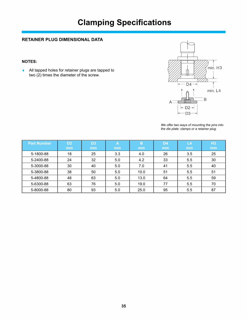
RETAINER PLUG DIMENSIONAL DATA
NOTES:
♦ All tapped holes for retainer plugs are tapped to two (2) times the diameter of the screw.
We offer two ways of mounting the pins into the die plate: clamps or a retainer plug.
Clamping Specifications
Part Number D2 mm
D3 mm
A mm
B mm
D4 mm
L4 mm
H3 mm
5-1800-88 18 25 3.3 4.0 26 3.5 255-2400-88 24 32 5.0 4.2 33 5.5 305-3000-88 30 40 5.0 7.0 41 5.5 405-3800-88 38 50 5.0 10.0 51 5.5 515-4800-88 48 63 5.0 13.0 64 5.5 595-6300-88 63 76 5.0 19.0 77 5.5 705-8000-88 80 93 5.0 25.0 95 5.5 87
36
Component Lubrication
BALL BEARING COMPONENTS
Recommended Lubrication:• Ball-Lube• Pint BALL-LUBE spray # ARL016 • Gallon BALL-LUBE # ARL128
Notes*:• Lubricates assemblies providing protection against wear, oxidation and rust• MSDS available upon request • Alternative / refined mineral oil of viscosity 290/340 SSU @ 100 degrees F containing “EP”
additives and rust inhibitors
SELF-LUBRICATING STyLE BUSHINGS OR WEAR PLATES WITH OIL IMPREGNATED GRAPHITE PLUGS
Recommended Lubrication:• Light 20 wt. oil should be applied to pre-lube the wear surface of the bushing
Notes*:• When bushing reaches 80-90 degrees F° because of friction between the components, oil is
drawn from the plug thus lubricating the wear surface
NEVER USE GREASE with the Self-Lubricating oil impregnated graphite plug products. Grease on the oil impregnated graphite plugs will prevent the self-lubricating process
PLAIN BEARING FRICTION
Recommended Lubrication:• Quart # 9-01-52• Gallon # 9-02-52• (15) Gallons # 9-02-522 • (55) Gallons # 9-02-521
Notes*:• Above die lubricant is specially prepared to provide efficient lubrication for guide post in plain
bearing applications • Alternative, lithium complex white grease or multi-purpose grease
*Note:MSDS available upon requestRecommendations are based on applications in typical ambient temperatures. For high / low temperature applications, a reputable Lubricant Company or lubrication specialist should be consulted.

37
Lifter Pins
Lifter pins are manufactured from 1144 steel and are commonly used to handle large die sets. They conform to NAAMS standards. The internal spring provides added assurance that the fall ring will function properly during the course of the pin’s use.
Product Features
LP50-190
Part NAAMS A B C D E F Total Die Wt. in Number Code mm mm mm mm mm mm Metric Tons (t)
LP35-125 L013512 35 125 165 45 10 21.5 0 – 2.72 LP50-190 L015019 50 190 230 63 10 31 2.72 – 9.07 LP63-280 L016328 63 280 320 76 10 37.5 9.07 – 36.28 LP80-320 L018032 80 320 370 89 15 46 36.28 – 72.57
+ 0- .03
38
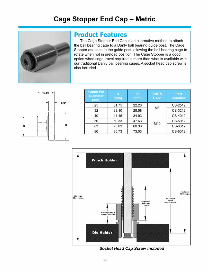
Cage Stopper End Cap – Metric
Product Features The Cage Stopper End Cap is an alternative method to attach the ball bearing cage to a Danly ball bearing guide post. The Cage Stopper attaches to the guide post, allowing the ball bearing cage to rotate when not in preload position. The Cage Stopper is a good option when cage travel required is more than what is available with our traditional Danly ball bearing cages. A socket head cap screw is also included.
D B
19.05
6.35
Socket Head Cap Screw included
Guide Pin Diameter
(mm)
B(mm)
D(mm)
SHCSUsed
Part Number
25 31.75 22.23M6
CS-251232 38.10 28.58 CS-321240 44.45 34.93
M10
CS-401250 60.33 47.63 CS-501263 73.03 60.33 CS-631280 85.73 73.03 CS-8012

39
These pad retainers are manufactured from 1144 steel and hardened to 28-34 Rockwell C-scale. They are machined to precise tolerances in order to retain the pad and assure parallelism during use.
Product Features
Pad Retainers –Standard Mount – Metric
NR50-50
NR50-30 30 40 NR50-40 40 45 NR50-45 45 50 NR50-50 50 55 NR50-60 60 65 NR50-65 65 70 NR50-70 70 75 NR50-75 75 75 NR50-90 90 100 NR50-100 100 110 NR50-115 115 120 NR50-130 130 140 NR50-140 140 150 NR50-160 160 170 NR70-40 40 45 NR70-45 45 50 NR70-50 50 55 NR70-60 60 65 NR70-65 65 70 NR70-70 70 75 NR70-75 75 75 NR70-90 90 100 NR70-100 100 110 NR70-115 115 120 NR70-130 130 140 NR70-140 140 150 NR70-160 160 170
PART Diam. Length Diam. Length NUMBER D2 (mm) L1 (mm) D1 (mm) L4 (mm)
40 50
60 70
PART LOAD NUMBER D1 D2 L2 L3 S1 S2 RATING NR50 50 40 35 15 M27 x 2 M16 x 2.0 192kN NR70 70 60 40 15 M36 x 3 M20 x 2.5 299kN

40
Pad Retainers –Reverse Mount – Metric
NR50-50R
These pad retainers are manufactured from 1144 steel and hardened to 28-34 Rockwell C-scale. They are machined to precise tolerances in order to retain the pad and assure parallelism during use.
Product Features
PART LOAD NUMBER D1 D2 F L3 RATING NR50 50 40 33.65 15 192kN NR70 70 60 53.70 15 299kN
NR50-30R 30 NR50-40R 40 45 NR50-45R 45 NR50-50R 50 55 NR50-60R 60 NR50-65R 65 NR50-70R 70 NR50-75R 75 NR50-90R 90 NR50-100R 100 NR50-115R 115 NR50-130R 130 NR50-140R 140 NR50-160R 160 NR70-40R 40 NR70-45R 45 NR70-50R 50 NR70-60R 60 NR70-65R 65 NR70-70R 70 NR70-75R 75 NR70-90R 90 NR70-100R 100 NR70-115R 115 NR70-130R 130 NR70-140R 140 NR70-160R 160
PART Diam. Length Diam. T1 NUMBER D2 (mm) L1 (mm) D1 (mm) (mm)
40 50 M16 x 2.0
60 70 M20 x 2.5

41
PINS & BUSHINGS – METRIC
The Danly IEM Value Proposition I. DANLy IEM is recognized as the leader in manufacturing quality die components to the global parts forming industry. Our reputation has been built by satisfying customer needs, and we are very strong in the automotive and appliance industries.
II. DANLy IEM offers outstanding delivery on a consistent basis. Choosing us as a supplier means that our customers have a competitive advantage in delivering their products to the market.
III. DANLy IEM has complex machining capabilities on die components at several facilities. With extensive machining capabilities in the USA and China, we have taken the lead role in creating and bringing new products to customers and helping them find solutions that improve their operations.
IV. DANLy IEM’s vast breadth of products assures innovative solutions. We strive to address customer problems by utilizing our research and development department as well as other technical professionals.
V. DANLy IEM has a technically trained sales force and distributor channels with Engineering support. Sales, Marketing and Engineering professionals are available to support our product lines.
...A LEADING MANUFACTURER AND INNOVATOR OF DIE COMPONENTS SUPPLIED GLOBALLY TO THE METAL
FORMING INDUSTRY...
Competitive PricesReliability and Performance
High Quality Design & ConstructionOutstanding Service & Support

© 2020 Dayton Lamina Corporation. All rights reserved.
Commitment to Quality & Customer Satisfaction
Dayton Lamina is a leading manufacturer of tool, die and mold components for the metal-working and plastics industries. As a customer-focused, world-class supplier of choice, we provide the brands, product breadth, distribution network and technical support for all your metal forming needs.
Our goal is to give our customers the most innovative and value-added products and services.
www.daytonlamina.com
*
*Dayton Lamina’s line of Danly products is available only to North America.
DS562 7/20


![CITATION: Nykamp v Demountable Sales & Hire Pty Ltd · CITATION: Nykamp v Demountable Sales & Hire Pty Ltd [2010] NTMC 051 PARTIES: ROBYN NYKAMP v DEMOUNTABLE SALES & HIRE PTY LTD](https://static.fdocuments.net/doc/165x107/5b46a8e97f8b9a15308b7a91/citation-nykamp-v-demountable-sales-hire-pty-citation-nykamp-v-demountable.jpg)