Bag-In/Bag-Out Operation and Maintenance Manual DESCRIPTION OF FLUID SEAL FILTER LOCKING SYSTEM The...
22
FILTRATION GROUP HEPA Seal Bag-In/Bag-Out Operation and Maintenance Manual II-H-BIBO p. 1-21
Transcript of Bag-In/Bag-Out Operation and Maintenance Manual DESCRIPTION OF FLUID SEAL FILTER LOCKING SYSTEM The...
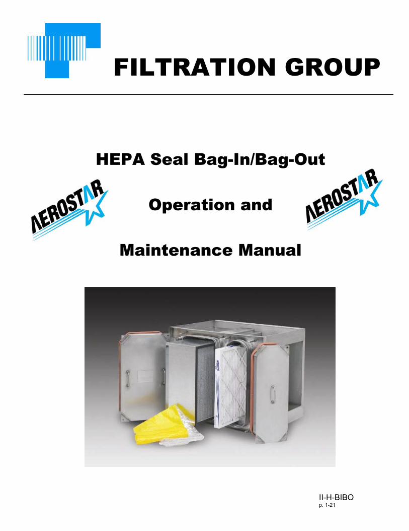
FILTRATION GROUP
HEPA Seal Bag-In/Bag- ut
Operation and
Maintenance Manua
O
l
II-H-BIBOp. 1-21
2
Table of Contents
SECTION PAGE
Manufacture’s Message 3
Introduction 4
Handling and Storage of Filter Elements 9
Installation of New Housings 9
Start up Procedures 10
Appendix A 19
Appendix B 20
3
MANUFACTURE’S MESSAGE
The HEPA Seal Bag In/Bag Out housings are designed to protectfacility personnel and the general public from dangerous materials byfiltering those materials. The filters that you are to change containthe filtered material. In order for you to be protected as fully aspossible, you must follow these instructions as amended by yourchief safety officer. The bagging method of changing a filter is notfoolproof, but it is the safest practical method available for changingcontaminated filter.
We realize that a single manual cannot address all types of housingdesigns and configurations, so we are offering the concepts ofinstalling a new filter(s) into a new system and replacing dirty filters insystems that are already in operation. Once the concept isunderstood, both maintenance personnel and safety personnel canadapt the most suitable method to use considering the housing,location, type of filter, and any other items that can affect safety.
Carefully study this manual and the safety officer’s amendments sothat you have the entire procedure in mind before attempting filterchange out. Be sure to have all tools and equipment on hand prior toactually beginning work. In this manual, we describe the FiltrationGroup banding method of sealing the bag.
The important thing to remember is to use this manual, your safetyofficer’s instructions, and your own reasoning ability to preventyourself and the immediate environment from being contaminatedwith the material that is captured on the dirty filter.
4
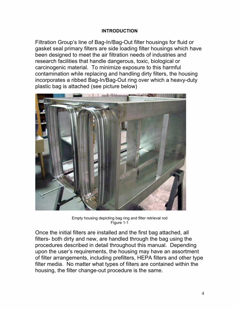
INTRODUCTION
Filtration Group’s line of Bag-In/Bag-Out filter housings for fluid orgasket seal primary filters are side loading filter housings which havebeen designed to meet the air filtration needs of industries andresearch facilities that handle dangerous, toxic, biological orcarcinogenic material. To minimize exposure to this harmfulcontamination while replacing and handling dirty filters, the housingincorporates a ribbed Bag-In/Bag-Out ring over which a heavy-dutyplastic bag is attached (see picture below)
Empty housing depicting bag ring and filter retrieval rodFigure 1-1
Once the initial filters are installed and the first bag attached, allfilters- both dirty and new, are handled through the bag using theprocedures described in detail throughout this manual. Dependingupon the user’s requirements, the housing may have an assortmentof filter arrangements, including prefilters, HEPA filters and other typefilter media. No matter what types of filters are contained within thehousing, the filter change-out procedure is the same.
5
• Note- Filter change out is incomplete unless the new filtershave been sealed to the housing frame and an in place leaktest has been performed.
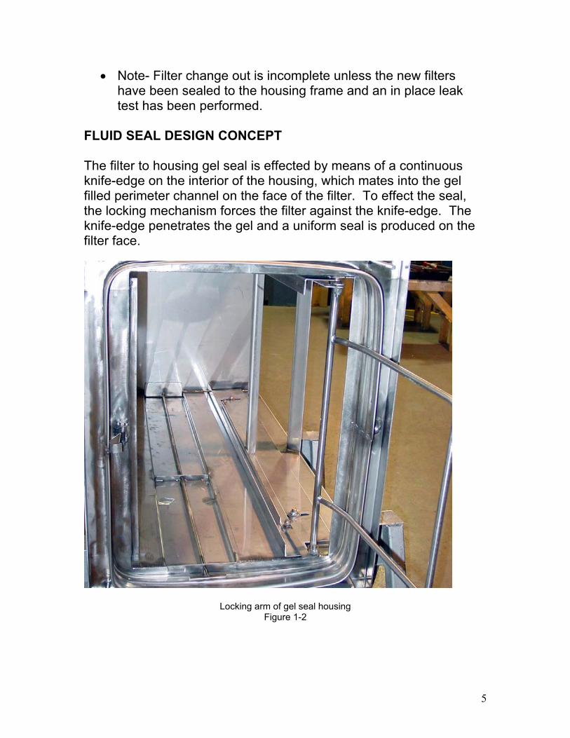
FLUID SEAL DESIGN CONCEPT
The filter to housing gel seal is effected by means of a continuousknife-edge on the interior of the housing, which mates into the gelfilled perimeter channel on the face of the filter. To effect the seal,the locking mechanism forces the filter against the knife-edge. Theknife-edge penetrates the gel and a uniform seal is produced on thefilter face.
Locking arm of gel seal housingFigure 1-2
6
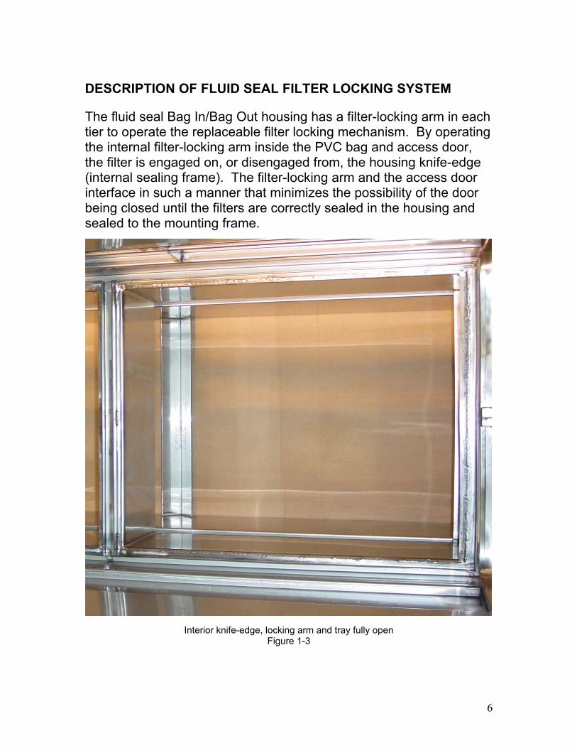
DESCRIPTION OF FLUID SEAL FILTER LOCKING SYSTEM
The fluid seal Bag In/Bag Out housing has a filter-locking arm in eachtier to operate the replaceable filter locking mechanism. By operatingthe internal filter-locking arm inside the PVC bag and access door,the filter is engaged on, or disengaged from, the housing knife-edge(internal sealing frame). The filter-locking arm and the access doorinterface in such a manner that minimizes the possibility of the doorbeing closed until the filters are correctly sealed in the housing andsealed to the mounting frame.
Interior knife-edge, locking arm and tray fully openFigure 1-3
7
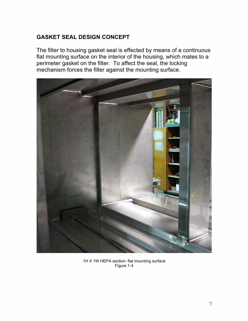
GASKET SEAL DESIGN CONCEPT
The filter to housing gasket seal is effected by means of a continuousflat mounting surface on the interior of the housing, which mates to aperimeter gasket on the filter. To affect the seal, the lockingmechanism forces the filter against the mounting surface.
1H X 1W HEPA section- flat mounting surfaceFigure 1-4
8
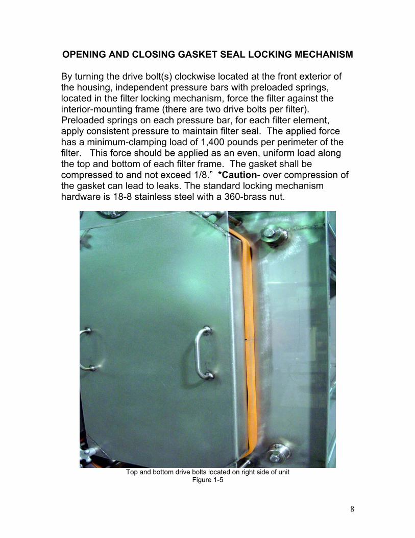
OPENING AND CLOSING GASKET SEAL LOCKING MECHANISM
By turning the drive bolt(s) clockwise located at the front exterior ofthe housing, independent pressure bars with preloaded springs,located in the filter locking mechanism, force the filter against theinterior-mounting frame (there are two drive bolts per filter).Preloaded springs on each pressure bar, for each filter element,apply consistent pressure to maintain filter seal. The applied forcehas a minimum-clamping load of 1,400 pounds per perimeter of thefilter. This force should be applied as an even, uniform load alongthe top and bottom of each filter frame. The gasket shall becompressed to and not exceed 1/8.” *Caution- over compression ofthe gasket can lead to leaks. The standard locking mechanismhardware is 18-8 stainless steel with a 360-brass nut.
Top and bottom drive bolts located on right side of unitFigure 1-5
9
HANDLING AND STORAGE OF FILTER ELEMENTS
Particulate filters include a wide range of filter types, sizes andperformance capabilities. These filters are designed to removeairborne particulates from an air stream. Filters can consist of 30%efficient by ASHRAE prefilters and up to 99.97% efficient HEPA (highefficiency particulate air) filters. In general, all particulate air filtersare fragile and should be handled with care. The followingprecautions should be observed upon storing filters:
• Keep in a clean low humidity air controlled environment.• Filter should remain in its original shipping. container with
correct orientation until put in use.• Temperature in storage area shall not be less than 0°
Fahrenheit or more than 100° Fahrenheit.• Stacking of filters is prohibited.• Moving of filters should be restricted- lest the media become
damaged.• Shelf life is no more than three years for both gasket and gel
seal filters (see manufacturer’s instructions)• All filter manufacture’s instructions and warnings shall be
followed as well.
INSTALLATION OF NEW HOUSINGS
1. Position the housing adjacent to the ductwork. Housing shouldbe welded, bolted or gasketed permanently to the ductwork.
2. Housing should be securely mounted to either a base or otherpermanent edifice.
3. Unit should be orientated as so the access door(s) can beeasily removed and replaced.
4. Following installation, ductwork and housing should be cleanedto eliminate any and all contaminants as well as any otheritems, which may have been stored in the unit during shipping.
5. Install filter(s).
10
6. Perform designated leak test/DOP test (designated by eitherthe chief safety officer or engineer) to insure that the unit isworking properly and is not leaking.
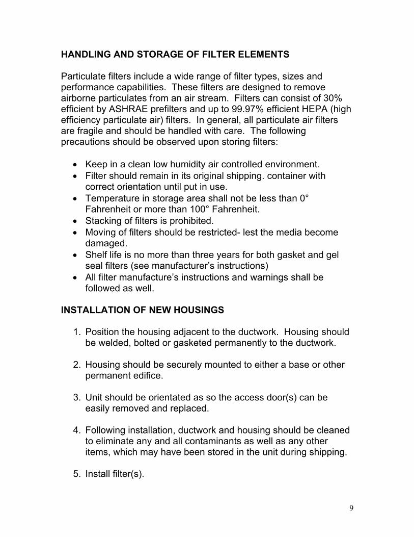
START UP PROCEDURES
• System must be shutdown prior to any filter installation orremoval. Airflow should be stopped or a bypass of the airsystem must be made. Any leakage through either thedampers or other airflow device will cause bag to sucktight against filter(s) and possibly cause damage to thebag.
• Consult with safety officer and perform both a job safetyanalysis prior to installing or removing any filter(s)andmake sure all personnel are wearing the requiredpersonal protective equipment (PPE).
1. Clean outside door, work area and all stainless steel surfaces.
1H X 1W unit with pre-filter sectionFigure 1-6
11
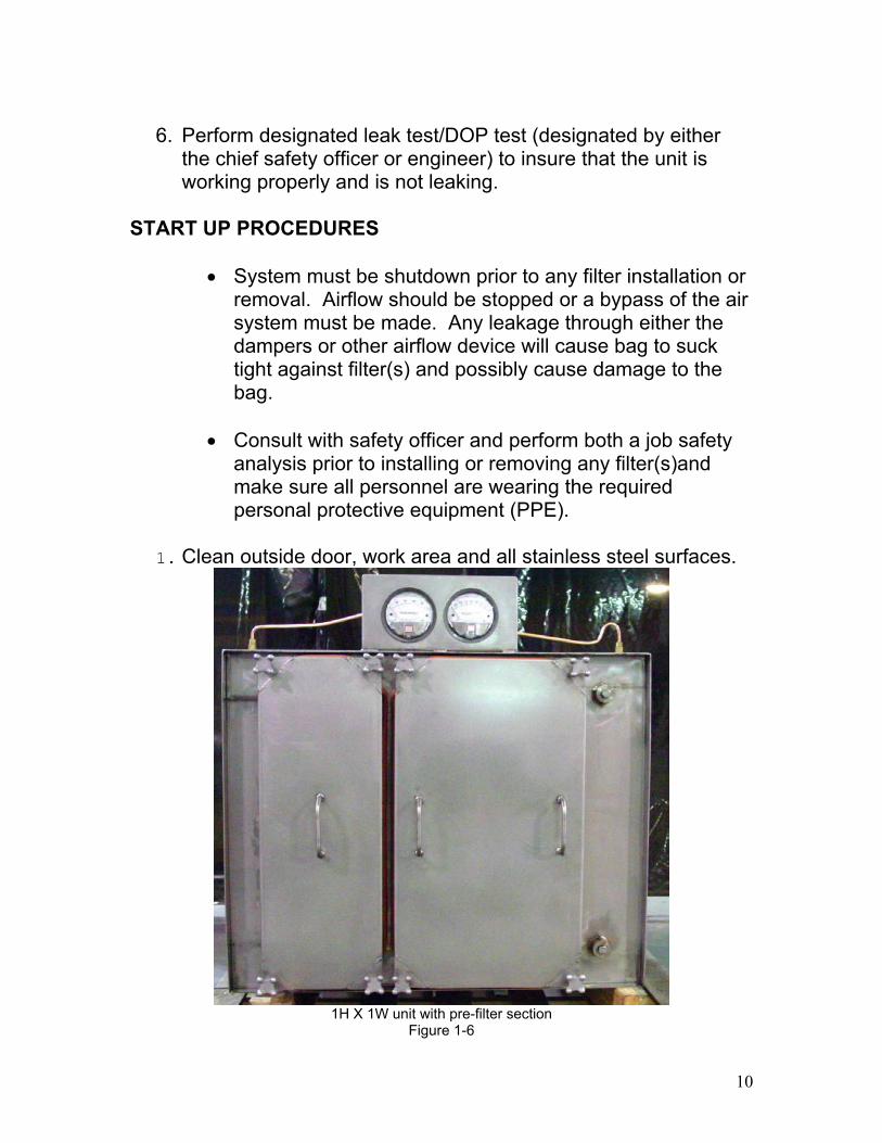
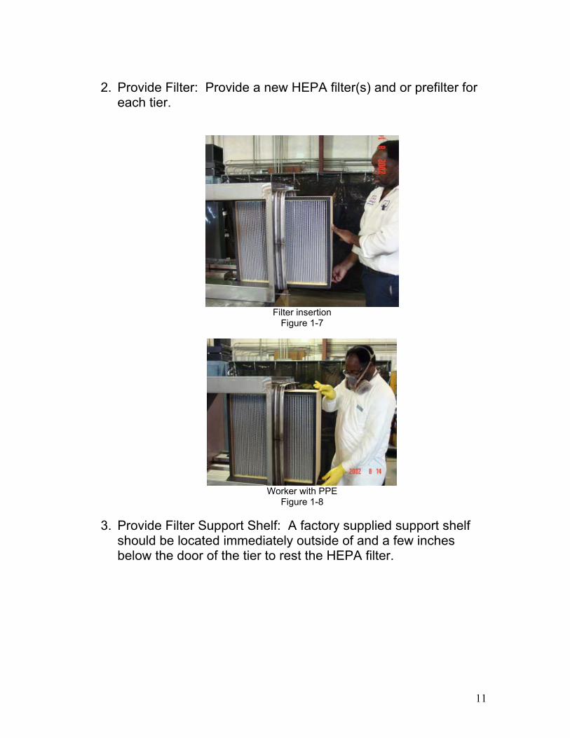
2. Provide Filter: Provide a new HEPA filter(s) and or prefilter foreach tier.
Filter insertionFigure 1-7
Worker with PPEFigure 1-8
3. Provide Filter Support Shelf: A factory supplied support shelfshould be located immediately outside of and a few inchesbelow the door of the tier to rest the HEPA filter.
12
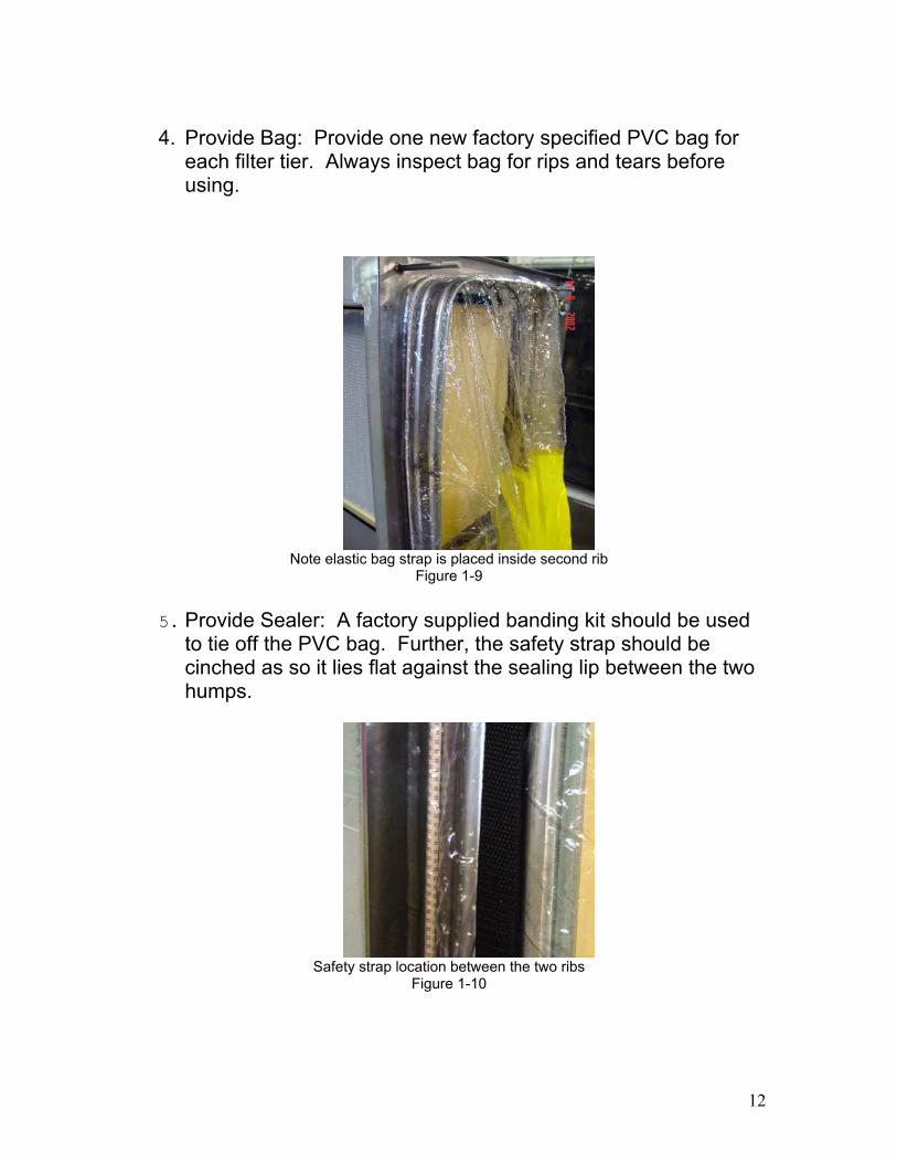
4. Provide Bag: Provide one new factory specified PVC bag foreach filter tier. Always inspect bag for rips and tears beforeusing.
Note elastic bag strap is placed inside second ribFigure 1-9
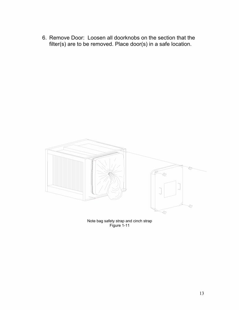
5. Provide Sealer: A factory supplied banding kit should be usedto tie off the PVC bag. Further, the safety strap should becinched as so it lies flat against the sealing lip between the twohumps.
Safety strap location between the two ribsFigure 1-10
13
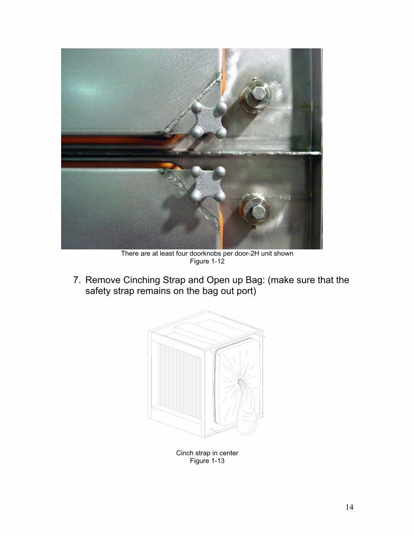
6. Remove Door: Loosen all doorknobs on the section that thefilter(s) are to be removed. Place door(s) in a safe location.
Note bag safety strap and cinch strapFigure 1-11
14
There are at least four doorknobs per door-2H unit shownFigure 1-12
7. Remove Cinching Strap and Open up Bag: (make sure that thesafety strap remains on the bag out port)
Cinch strap in centerFigure 1-13
15
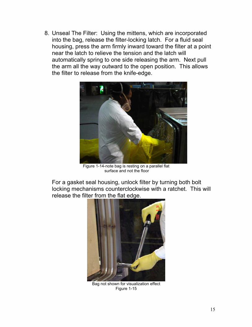
8. Unseal The Filter: Using the mittens, which are incorporatedinto the bag, release the filter-locking latch. For a fluid sealhousing, press the arm firmly inward toward the filter at a pointnear the latch to relieve the tension and the latch willautomatically spring to one side releasing the arm. Next pullthe arm all the way outward to the open position. This allowsthe filter to release from the knife-edge.
Figure 1-14-note bag is resting on a parallel flat surface and not the floor
For a gasket seal housing, unlock filter by turning both boltlocking mechanisms counterclockwise with a ratchet. This willrelease the filter from the flat edge.
Bag not shown for visualization effectFigure 1-15
16
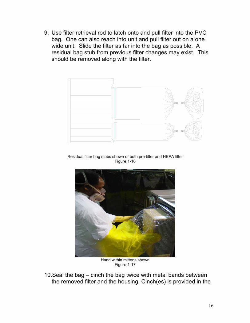
9. Use filter retrieval rod to latch onto and pull filter into the PVCbag. One can also reach into unit and pull filter out on a onewide unit. Slide the filter as far into the bag as possible. Aresidual bag stub from previous filter changes may exist. Thisshould be removed along with the filter.
Residual filter bag stubs shown of both pre-filter and HEPA filterFigure 1-16
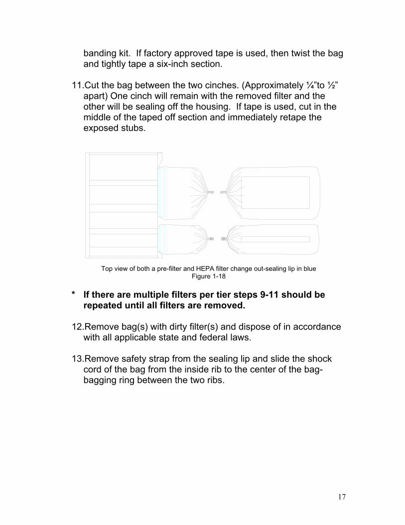
Hand within mittens shownFigure 1-17
10.Seal the bag – cinch the bag twice with metal bands betweenthe removed filter and the housing. Cinch(es) is provided in the
17
banding kit. If factory approved tape is used, then twist the bagand tightly tape a six-inch section.
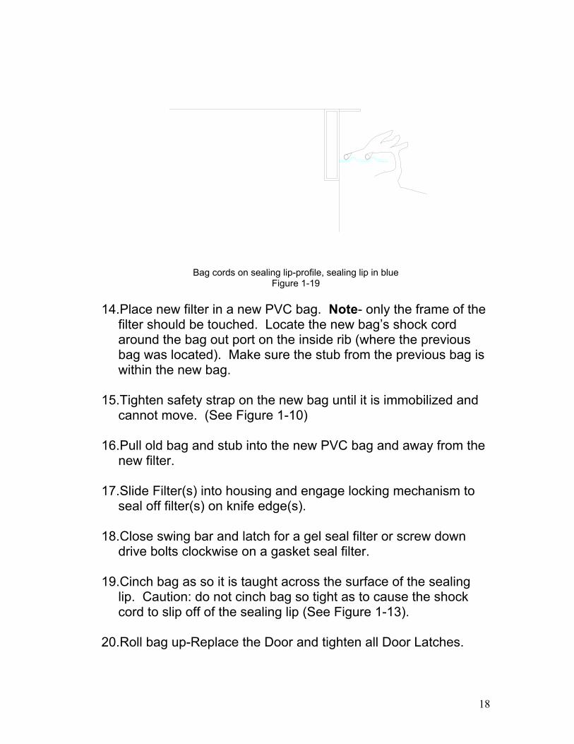
11.Cut the bag between the two cinches. (Approximately ¼”to ½”apart) One cinch will remain with the removed filter and theother will be sealing off the housing. If tape is used, cut in themiddle of the taped off section and immediately retape theexposed stubs.
Top view of both a pre-filter and HEPA filter change out-sealing lip in blueFigure 1-18
* If there are multiple filters per tier steps 9-11 should berepeated until all filters are removed.
12.Remove bag(s) with dirty filter(s) and dispose of in accordancewith all applicable state and federal laws.
13.Remove safety strap from the sealing lip and slide the shockcord of the bag from the inside rib to the center of the bag-bagging ring between the two ribs.
18
Bag cords on sealing lip-profile, sealing lip in blueFigure 1-19
14.Place new filter in a new PVC bag. Note- only the frame of thefilter should be touched. Locate the new bag’s shock cordaround the bag out port on the inside rib (where the previousbag was located). Make sure the stub from the previous bag iswithin the new bag.
15.Tighten safety strap on the new bag until it is immobilized andcannot move. (See Figure 1-10)
16.Pull old bag and stub into the new PVC bag and away from thenew filter.
17.Slide Filter(s) into housing and engage locking mechanism toseal off filter(s) on knife edge(s).
18.Close swing bar and latch for a gel seal filter or screw downdrive bolts clockwise on a gasket seal filter.
19.Cinch bag as so it is taught across the surface of the sealinglip. Caution: do not cinch bag so tight as to cause the shockcord to slip off of the sealing lip (See Figure 1-13).
20.Roll bag up-Replace the Door and tighten all Door Latches.
19
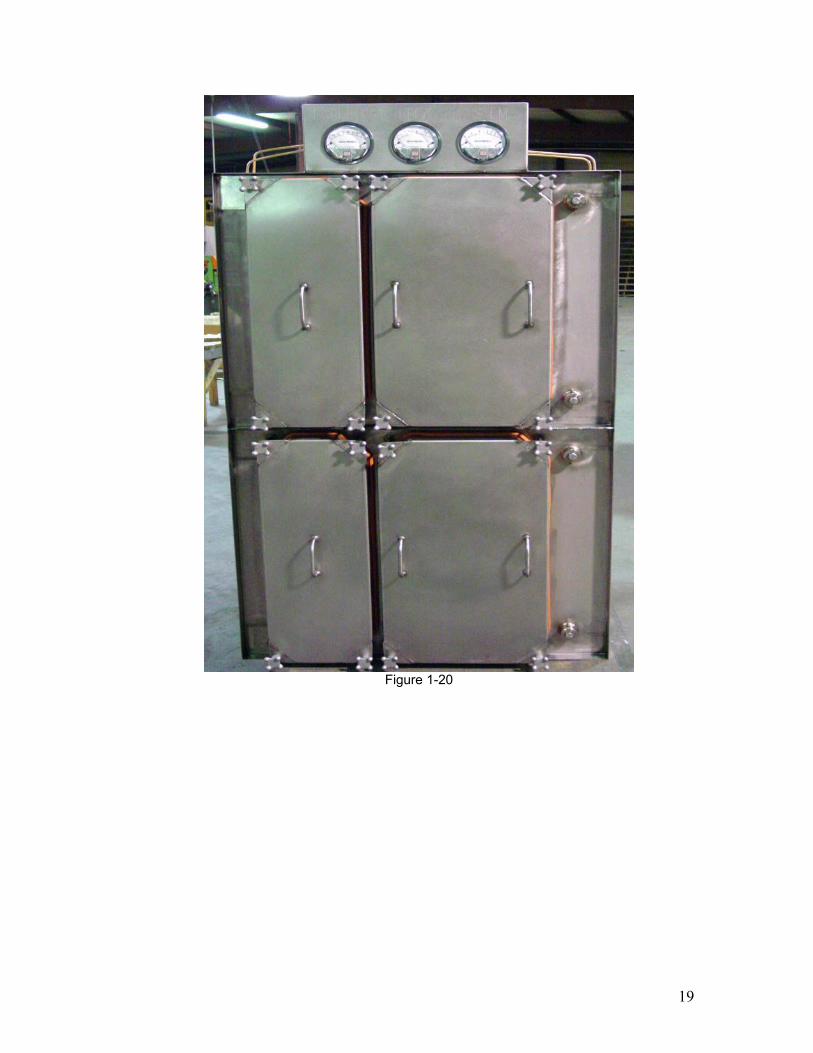
Figure 1-20
20
APPENDIX A
It is recommended that the buyer supply complete informationabout the operating conditions of the ventilation system prior toinstallation of any Bag In/Bag Out contamination system. Locationspecific conditions may prevent the system from operatingsatisfactorily for certain applications. Any non-factory alterations tothe product may result in a compromised installation. Pleasecontact manufacturer for any questions not addressed in thismanual.
Filtration Group Inc912 E. Washington Street
Joliet, IL 60433Phone 1-800-739-4600
Fax 1-800-518-1162http:\\www.filtrationgroup.com
21
APPENDIX B
LOCKING TRAY CHANGE OUT
It is advised that any locking tray mechanism replacement orchange out be done in a decontaminated environment. Due tosharp edges, placing a metal locking tray in a PVC bag is notrecommended. However, one of the advantages of the HEPASeal Bag In/Bag Out contamination housing is the ability tochange out locking trays in the field.
Change out is a simple task. The same concept applies to lockingmechanisms as that to filters (refer back to start up procedures).
First, remove all filters from the contamination unit following theStart Up Procedures aforementioned. Insert a new bag with astandard ratchet with a ½” socket in the bag. For Gel seal units a3/8” socket will be needed as well. Position the new PVC bag’sshock cord the same way you would for a PVC bag with a newfilter in it. Remove the old bag stub in the new bag.
FLUID SEAL METHOD1. Using the ratchet with the ½” socket remove the two hex
nuts and washers for both the top and bottom locking trays.
2. Then switch to the 3/8” socket and remove the hex nut andwashers from the linkage to the door swing arm.
3. Remove both the top and bottom parts to each pair oflocking trays and pull into the PVC bag.
4. Treat the locking mechanism as a dirty filter and continue theappropriate steps.
• Warning- ratchet and socket must remain in the bag.Do not remove.
22
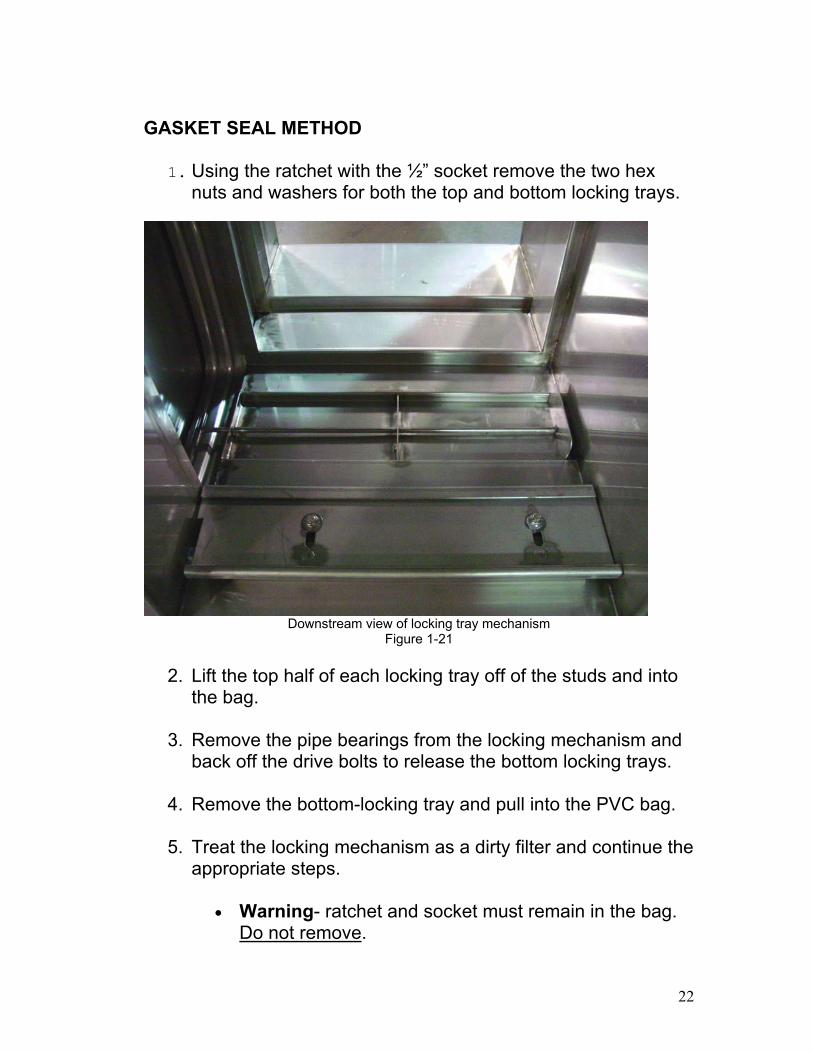
GASKET SEAL METHOD
1. Using the ratchet with the ½” socket remove the two hexnuts and washers for both the top and bottom locking trays.
Downstream view of locking tray mechanismFigure 1-21
2. Lift the top half of each locking tray off of the studs and intothe bag.
3. Remove the pipe bearings from the locking mechanism andback off the drive bolts to release the bottom locking trays.
4. Remove the bottom-locking tray and pull into the PVC bag.
5. Treat the locking mechanism as a dirty filter and continue theappropriate steps.
• Warning- ratchet and socket must remain in the bag.Do not remove.