BAE Systems Naval Ships - MATLAB€¦ · BAE Systems Naval Ships ... electrical supply etc. ... •...
32
BAE Systems Naval Ships Dynamic Modelling and Simulation to Design, Integrate, and Assess Performance of Naval Systems Howard Williams, MEng MRAeS CEng BAE Systems Maritime – Naval Ships Combat System Peter Worthington, BEng MIMechE CEng BAE Systems Maritime - Naval Ships
Transcript of BAE Systems Naval Ships - MATLAB€¦ · BAE Systems Naval Ships ... electrical supply etc. ... •...

BAE Systems Naval ShipsDynamic Modelling and Simulation to Design, Integrate, and Assess
Performance of Naval Systems
Howard Williams, MEng MRAeS CEng
BAE Systems Maritime – Naval Ships Combat System
Peter Worthington, BEng MIMechE CEng
BAE Systems Maritime - Naval Ships

Content
• Introduction to Naval Ships
• The Application of:
• MATLAB and Simulink
• Simulink Coder and Embedded Coder
• MATLAB Coder
• Type 26 CS Performance Assessment
• Role of Combat Systems
• Role of Modelling
• Our Mission
• What we Model
7th October 2014© BAE Systems 2
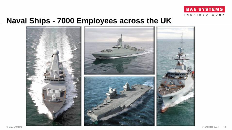
Naval Ships - 7000 Employees across the UK
7th October 2014© BAE Systems 3
Rosyth
Filton
Portsmouth
Glasgow
Frimley
New Malden
Dorchester

Key Platforms
FAST ATTACK CRAFT
Displacement 720 ton
Length 62 m
Top speed 36 kts
Range 750 nm
Crew size 50
TYPE 45 DESTROYER
Displacement 7,500 ton
Length 152.4
Top speed 27 kts
Range 7,000 nm
Crew size 190
Embarked forces 30
TYPE 26 GLOBAL COMBAT SHIP*
Displacement 5,400 ton
Length 148 m
Top speed 28 kts +
Range 7,000 nm
Crew size 118
Embarked forces 72
Endurance 60 days
*Based on current concept design
QE CLASS AIRCRAFT CARRIER
Displacement 65,000 ton
Length 280m
Top speed 25 kts
Range 10,000 nm
Crew size 679
Embarked forces Up to 921
OFFSHORE PATROL VESSEL
Variant 90m
Displacement 1,800
Length 90m
Top speed 25 kts
Range 5,500nm
Crew Size 70
Embarked forces 50
Endurance 35 days
CORVETTE
Displacement 2,660 ton
Length 99 m
Top speed 25 kts
Range 4,500 nm
Crew size 103
Endurance 21 days

HMS Queen Elizabeth
7th October 2014© BAE Systems 5

THE APPLICATION OF MATLAB AND SIMULINKBAE Systems Naval Ships
7th October 2014© BAE Systems 6

MATLAB & Simulink Analysis
MATLAB and Simulink products replaced Fortran in the early 90s. Typically used by
specialists to analyse systems within the naval domain.
• Replenishment at Sea (RAS)
• Loading/loading of Landing Craft
• Aircraft Carrier Steam Systems
• Shock Mounting System Assessments
• Helicopter Lashings
7th October 2014© BAE Systems 7

Helicopter Handling Analysis
‘Shipborne handling arrangements require a capability to capture, move and
restrain aircraft of one or more types in high sea states and adverse weather
conditions’
Overview
• Simulation developed in MATLAB and Simulink
• Generation of extreme sea state conditions
• Validated baseline Simulink model
• Additional modules added to a baseline model
• Visualisation used to illustrate results
• Used to support platform safety case development
7th October 2014© BAE Systems 8

Analysis Overview
7th October 2014© BAE Systems 9

Summary Points
• Integral part of acceptance process
• Enabled examination at extreme Sea States
• Confirmation of the acceptability of dynamic loads
to the Aircraft and Ship Design Authorities
• Definition of safe operating limits
• PRISM System accepted into service through
simulated trial
• Cost effective as simulation reduced the sea trial
requirement
7th October 2014© BAE Systems 10
0 20 40 60 80 100 120 140 160 1801.2
1.3
1.4
1.5
1.6
1.7x 10
4
Encounter Angle (degrees)
Forc
e (
N)
Minimum Reaction Force
10 knots
15 knots
20 knots
25 knots
0 20 40 60 80 100 120 140 160 1802
2.05
2.1
2.15
2.2x 10
4
Encounter Angle (degrees)
Forc
e (
N)
Maximum Reaction Force
10 knots
15 knots
20 knots
25 knots
0 15 30 45 60 75 105 120 135 150 165 1800
0.5
1
1.5
2
2.5
3x 10
4
Encounter Angle (degrees)
Forc
e (
N)
Wire Maximim Force
25 knots
20 knots
15 knots
10 knots

THE APPLICATION OF SIMULINK CODER
AND EMBEDDED CODER
On-Board Training Plant Simulation
7th October 2014© BAE Systems 11

Type 45 Platform Management System (PMS)
• Used to control and monitor plant, fire/flood alarms and tank contents etc.
• Plant auto-start to maintain pressure, electrical supply etc.
• Automatic system reconfiguration, system interlocks, start/stop sequencing
• Weapons management support
• Distributed across platform for “Graceful Degradation”
• 13,500+ control and monitoring signals
• 300+ screens
7th October 2014© BAE Systems 12

Type 45 PMS On-board Trainer
7th October 2014© BAE Systems 13
Ship Control Centre
TanksPumpPLC
Server
ValvesDG
Zone Control Posts
• Utilises any of the PMS workstations
• Flexible Instructor fault insertion and control
• Maintain PMS look and “feel real”
• Coverage: 16 Systems
• PMS Trainer integrated into every Type 45
• Shore-based Trainers at HMS Phoenix and HMS Sultan
• 530 Faults - e.g. ruptures, floods, trips etc.
• 20+ Hardware Outstations e.g. DG, GT and HV Panels

Why Simulink and Embedded Encoder?
Simulink?
• Simulink used within the group ‘our tool of choice’
• Simulink environment increases flexibility, allows Mechanical, Electrical and Software
Engineers to work together
• A high level description that can be run, tuned and tested
Simulink Coder and Embedded Coder?
• Generated code executable exactly as the Simulink model
• Enhanced code performance with no dependency upon Simulink model
• No baggage in the form of Windows references
• Embedded Coder chosen to minimise local variable memory ‘mushrooming’
• Generated code easily tailored for external control and initial states.
7th October 2014© BAE Systems 14

Modelling Methodology
7th October 2014© BAE Systems 15
)( uefwdDGLossTorqfwdLoadTorquedDGTorquefwKdt
dFd
dfwd
Where Kd = (1000/(2p*InertiaDG)SRS
Simulink
Model
Model
Response
1195
59.7 Hz1188
59.4 Hz
1247
62.35 Hz
Simulink
Output
Plant Simulation
DLL
Auto code
Generation
C++
Code
DG FAT
Data

Modelling Comments
• Individual system models developed and tested before integration
• Consolidated test harness used for overall system
• All faults represent a physical event e.g. fuel supply pipe rupture causing a diesel
to stop, diesel tank to empty and the bilge to fill.
• Discrete time step – auto coding requirement!
• Goto/From tags used extensively within model to reduce complexity
• All tags and scopes generated automatically from PMS specification
• Hierarchal cascade of library systems and components
• Large initialisation state incorporating an automated capture process
7th October 2014© BAE Systems 16

In Summary
• Concurrent development with Type 45 systems
• Common Ship/Shore based Plant Simulation Model
• 16 Systems, 10000+ I/O and 530 Instructor Faults
• PMS, Instructor and Local Control
• 14 Local Control Panels and Outstations
• Approx. 250,000 lines of ‘error free’ c code generated
• Cost effective code generation – 3 man project team
• The design resides within the Simulink model and not the c code
• Plant simulation executable much smaller and more efficient than Simulink model
• Fast turnaround – functionality changes approx. 1 day
7th October 2014© BAE Systems 18

THE APPLICATION OF MATLAB COMPILERApplication Development
7th October 2014© BAE Systems 19

TRACIT Combat System Analysis Tool
Provides graphical and statistical information characterising the performance of
sensors and Command System
• Developed using MATLAB
• Deployed using MATLAB Compiler
• Compares sensors with true data
• Capable of handling large data sets
• Fast and versatile analysis
7th October 2014© BAE Systems 20
Using TRACIT
• Provides a rapid and reliable Combat Systems assessment within hours of the data being
made available
• Provides an indication of Tactical Picture Quality by a single number with readily understood
charts and animations
• Easily adapted to Combat Systems with differing sensors etc.
• Process uses data recorded entirely within the platform under test and does not require the
use of expensive 'ground truth' data
• Tactical Picture quality can be assessed without the need for an expensive formally
constituted trial
• Used primarily to generate evidence from trials to support system acceptance
7th October 2014© BAE Systems 21

Shock Mounting Assessment Tool
• Interface developed using MATLAB Guide
• Underpinned by a MATLAB 6DoF model
• Compiled application deployed directly into project
• Automated and standardised reporting
7th October 2014© BAE Systems 22

Shock Mounting Assessment Tool
• Created an effective, efficient and repeatable design process
• Designers have access to a specialist mounting system design tool
• Design assessment integral to the design process
• Provided an audit trail for mounting system acceptance
• Reduce the cost of mounting design and re-work
• Commonality of mount design reduced through life platform costs
7th October 2014© BAE Systems 23

Howard WilliamsBAE Systems Maritime – Naval Ships Combat System
T26 Combat System Performance Assessment Manager
• Role of Combat Systems
• Role of Modelling
• Our Mission
• What we Model
7th October 2014© BAE Systems 24
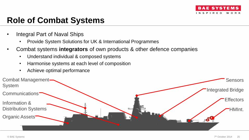
Role of Combat Systems
• Integral Part of Naval Ships
• Provide System Solutions for UK & International Programmes
• Combat systems integrators of own products & other defence companies
• Understand individual & composed systems
• Harmonise systems at each level of composition
• Achieve optimal performance
Effectors
Sensors
CommunicationsIntegrated Bridge
Combat Management
System
Information &
Distribution Systems
Organic Assets
HMInt.
7th October 2014© BAE Systems 25

Role of Modelling
• Assess the Combat System at varying levels of system composition & provide disclosure of
expected performance through life
• To manage the customer
• To understand performance sensitivity
• To support the engineering team
• Traditionally Achieved:
• Islands of specialist tools
• Limited Integration
• Large volume of data transportation & translation
• Large volume of qualitative post processing
• Vital to change this methodology “Combat Systems Role: Integrator of systems”
7th October 2014© BAE Systems 26

• Combine these tools under a Unified Ship Integration Modelling Tool
• Integrated with System Engineering Tools
• Push the tools to the front line
• Deliver through life product understanding to the customer
• Continually Enhance & Develop the tools capability
Our Mission
Integrated Architectural
Framework
7th October 2014© BAE Systems 27

Modelling - Assessment Framework
7th October 2014© BAE Systems 28

Modelling
7th October 2014© BAE Systems 29

Modelling – Interfaces (Data)
7th October 2014© BAE Systems 30

TRACIT
SADM
Modelling– Interfaces (Tools)
HMI
CMS
UNISIM
Interface Data
7th October 2014© BAE Systems 31

How we Deliver- UNISIM ApplicationModels Functionality Embedded in Intuitive UI
• Utilise New Application functionality
• MATLAB Graphics
Through-life Deployment Package underpinned by MathWorks products
• MATLAB Compiler
UNISIM Developer
UNISIM Deployed
UNISIM Packaged
7th October 2014© BAE Systems 32

Copyright 2014 BAE Systems. All rights reserved.
Thank you