Background Statement for SEMI Draft Document 3846 info...
42
i Background Statement for SEMI Draft Document 3846 info Revision to SEMI E10-0304E, SPECIFICATION FOR DEFINITION AND MEASUREMENT OF EQUIPMENT RELIABILITY, AVAILABILITY, AND MAINTAINABILITY (RAM) AND UTILIZATION NOTICE: This background statement is not part of the balloted item. It is provided solely to assist the recipient in reaching an informed decision based on the rationale of the activity that preceded the creation of this document. NOTICE: Recipients of this document are invited to submit, with their comments, notification of any relevant patented technology or copyrighted items of which they are aware and to provide supporting documentation. In this context, “patented technology” is defined as technology for which a patent has issued or has been applied for. In the latter case, only publicly available information on the contents of the patent application is to be provided. Background The E10-0304E standard is past the mandatory 5-year review period and in need of a thorough review by the user community. At the same time, the E10 Revision Task Force has undergone their own review of the document in order to clarify and expand the content based on user input and experiences. It is our belief that we have not changed the overall intent of E10 and have only made changes and additions to further its aim of defining the method to consistently measure equipment RAM and Utilization. The major revisions include: • multi-path cluster tool RAM metrics moved to the main body as official metrics • clarification and addition of new definitions • several new metrics added and some previous metrics updated or retired • metrics have been standardized for all equipment types, including multi-path cluster tools This revised document is submitted as an informational “blue” ballot for the user community to review and submit feedback for the E10 Revision Task Force. We acknowledge the document is not yet in full compliance with the SEMI Standards Style Manual and ask the reviewers to focus only on the technical content. Due to the extensive nature of the editing, no mark-up version of the changes is provided so the main body and Related Information 1 of the draft should be reviewed in their entirety. The breakout of Total Time into the six E10 major states of Productive Time, Standby Time, Engineering Time, Scheduled Downtime, Unscheduled Downtime and Non-Scheduled Time has not been fundamentally changed. As part of this revision, we have promoted the multi-path cluster tool RAM metrics section from Related Information 1 in E10-0304E to the main body of the revised document, which will formalize this material and make it an official part of the E10 standard. In addition, state priority reporting was added to the multi-path cluster tool RAM metrics. A large number of definitions were either substantially revised or added; in many cases the added definitions are from other SEMI Standards. These are: component part, consumable material, consumable part, continuous downtime event, downtime event, equipment, equipment module, equipment-related failure, equipment system, failure, host, intended function, intended process set, key group, mainframe, multi-path cluster tool, non-cluster tool, non-consumable part, non-processing module, non-supplier, observation period, processing module, recipe, single- path cluster tool, state, supplier, system, and training (off-line). Of these definition changes, the reviewer will want to focus on changes to differentiate consumable materials and consumable parts and the clause added to the failure definition to clarify that subsequent problems occurring during a continuous unscheduled downtime are not counted as additional failures. In addition, the term ‘Intended Process Flow’ was changed to ‘Intended Process Set’ and added as a definition. This is more equipment-centric terminology and reduces confusion with other definitions for ‘process flow’.
-
Upload
vuongkhanh -
Category
Documents
-
view
234 -
download
1
Transcript of Background Statement for SEMI Draft Document 3846 info...

i
Background Statement for SEMI Draft Document 3846 info Revision to SEMI E10-0304E, SPECIFICATION FOR DEFINITION AND MEASUREMENT OF EQUIPMENT RELIABILITY, AVAILABILITY, AND MAINTAINABILITY (RAM) AND UTILIZATION
NOTICE: This background statement is not part of the balloted item. It is provided solely to assist the recipient in reaching an informed decision based on the rationale of the activity that preceded the creation of this document.
NOTICE: Recipients of this document are invited to submit, with their comments, notification of any relevant patented technology or copyrighted items of which they are aware and to provide supporting documentation. In this context, “patented technology” is defined as technology for which a patent has issued or has been applied for. In the latter case, only publicly available information on the contents of the patent application is to be provided.
Background
The E10-0304E standard is past the mandatory 5-year review period and in need of a thorough review by the user community. At the same time, the E10 Revision Task Force has undergone their own review of the document in order to clarify and expand the content based on user input and experiences. It is our belief that we have not changed the overall intent of E10 and have only made changes and additions to further its aim of defining the method to consistently measure equipment RAM and Utilization. The major revisions include:
• multi-path cluster tool RAM metrics moved to the main body as official metrics
• clarification and addition of new definitions
• several new metrics added and some previous metrics updated or retired
• metrics have been standardized for all equipment types, including multi-path cluster tools
This revised document is submitted as an informational “blue” ballot for the user community to review and submit feedback for the E10 Revision Task Force. We acknowledge the document is not yet in full compliance with the SEMI Standards Style Manual and ask the reviewers to focus only on the technical content. Due to the extensive nature of the editing, no mark-up version of the changes is provided so the main body and Related Information 1 of the draft should be reviewed in their entirety.
The breakout of Total Time into the six E10 major states of Productive Time, Standby Time, Engineering Time, Scheduled Downtime, Unscheduled Downtime and Non-Scheduled Time has not been fundamentally changed.
As part of this revision, we have promoted the multi-path cluster tool RAM metrics section from Related Information 1 in E10-0304E to the main body of the revised document, which will formalize this material and make it an official part of the E10 standard. In addition, state priority reporting was added to the multi-path cluster tool RAM metrics.
A large number of definitions were either substantially revised or added; in many cases the added definitions are from other SEMI Standards. These are: component part, consumable material, consumable part, continuous downtime event, downtime event, equipment, equipment module, equipment-related failure, equipment system, failure, host, intended function, intended process set, key group, mainframe, multi-path cluster tool, non-cluster tool, non-consumable part, non-processing module, non-supplier, observation period, processing module, recipe, single-path cluster tool, state, supplier, system, and training (off-line).
Of these definition changes, the reviewer will want to focus on changes to differentiate consumable materials and consumable parts and the clause added to the failure definition to clarify that subsequent problems occurring during a continuous unscheduled downtime are not counted as additional failures. In addition, the term ‘Intended Process Flow’ was changed to ‘Intended Process Set’ and added as a definition. This is more equipment-centric terminology and reduces confusion with other definitions for ‘process flow’.

ii
For consistency and ease of application, metrics have been standardized so one comprehensive set of metrics can be used for each intended process set (IPS) and the following equipment types: non-cluster tools, single-path cluster tool, multi-path cluster tool, and individual equipment modules that are part of a single-path cluster tool or multi-path cluster tool. The reviewer will want to focus on this major change from the prior limited set of unique metrics for IPSs and multi-path cluster tools. To assist the reviewer in understanding these changes, please review the table below:
Metric Status in Blue Ballot
Motivation
MTBFp No change MFDp New Mean failure duration for failures during productive time is a
companion metric to MTBFp that supports calculation of “inherent availability” for a renewal cycle of strictly productive time and related time for failures.
E-MTBFp No change MTBFu New MFDu New E-MTBFu New
Added as alternative to MTBFp, etc. where engineering time and standby time are considered part of “normal” equipment operation and not exempt from reliability measurement (e.g., equipment undergoing acceptance testing and qualification prior to production release or being used primarily for long-term process development).
MCBF RETIRED E-MCBF RETIRED MCBFu New E-MCBFu New MCBFp New E-MCBFp New
Changed to specific uptime and productive time versions for consistency with MTBF metrics.
Total Uptime New Added for consistency and completeness with utilization metrics and to bridge to uptime definition in E79.
Operational Uptime No change Equipment Dependent Uptime UPDATE Supplier Dependent Uptime UPDATE Equipment Dependent Scheduled Downtime
UPDATE
Supplier Dependent Scheduled Downtime
UPDATE
Equipment Dependent Unscheduled Downtime
New
Supplier Dependent Unscheduled Downtime
New
Metrics are redefined to more clearly and accurately reflect the original intention. Whereas the original denominator subtracts quantities from operations time to imply a conditional operations time, the new denominator is defined as the sum of explicit quantities with the same objective. Unscheduled downtime metrics are added for completeness and consistency to demonstrate that the conditional uptime, scheduled downtime, and unscheduled downtime add up to 100% of the conditional operations time.
MTTPM New A new metric with a similar concept to MTTR, but to measure equipment system maintainability in terms of just PM time.
MTTR No change E-MTTR No change MTOL No change TFR New Impairment Time New
Two fundamentally new metrics that measure against a 24x7 timeline regardless of equipment system complexity. TFR measures the count of module failure events and Impairment Time measures time when one or more module failures is ongoing. These are simple, pragmatic measurements of maintainability, especially for multi-path cluster tools.
Operational Utilization No change Total Utilization No change

iii
A new Related Information 1 section “MTBF, Renewal Processes, and the Exponential Distribution” was added to explain the origins of MTBF and why it is significant in regards to predicting survival times. As this is Related Information, it is not an official part of the standard.
A completely revised Related Information 2 section (replacing prior Related Information 1) is also planned to give examples for calculating the new multi-path cluster tool metrics, but it has not been completed yet. Once this technical content is completed in the main body, appropriate examples will be created.
These following sections have not had any significant changes from E10-0304E:
Appendix 1: CONFIDENCE BOUND FACTORS
Appendix 2: RELIABILITY GROWTH OR DEGRADATION MODELS
Note concerning SEMI E58:
Changes and additions to the substates of E10 states will result in the revised document being temporarily out of synch with E58. The E58 ARAMS TF will need to come out of hiatus at a future date to make these changes or the E10 Revision TF may have to do so. In addition for consistency to E58, the revision now uses E58 state abbreviations (PRD, SBY, etc.) and references to time have been replaced by state or substate where appropriate.
Review Information
Task Force Review Group: E10 Revision Task Force Date: March 28, 29, 30, 2011 Time & Timezone: 0800-1200 PDT (Each day) Location: SEMI HQ City, State/Country: San Jose, CA Leader(s): Michael Werre (Intel)
David Busing (KLA-Tencor) Standards Staff: Ian McLeod (SEMI NA)
408.943.6996 [email protected]

This is a draft document of the SEMI International Standards program. No material on this page is to be construed as an official or adopted standard. Permission is granted to reproduce and/or distribute this document, in whole or in part, only within the scope of SEMI International Standards committee (document development) activity. All other reproduction and/or distribution without the prior written consent of SEMI is prohibited.
Page 1 Doc. 3846 SEMI
Semiconductor Equipment and Materials International 3081 Zanker Road San Jose, CA 95134-2127 Phone:408.943.6900 Fax: 408.943.7943
INF
OR
MA
TIO
NA
L B
AL
LO
T
DRAFTDocument Number: 3846
Date: 2011/02/25
SEMI Draft Document 3846 info Revision to SEMI E10-0304E, SPECIFICATION FOR DEFINITION AND MEASUREMENT OF EQUIPMENT RELIABILITY, AVAILABILITY, AND MAINTAINABILITY (RAM) AND UTILIZATION
1 Purpose
1.1 This document establishes a common basis for communication between users and suppliers of semiconductor manufacturing equipment by providing standards for measuring RAM and utilization performance of that equipment system in a manufacturing environment.
2 Scope
2.1 The document defines six mutually exclusive basic states into which all conditions and periods of time for an equipment system must fall. One state called unscheduled downtime defines a “failed” state for an equipment system. The measurement of equipment system reliability in this document concentrates on the relationship of equipment system failures to equipment system usage.
2.2 All metrics defined herein are applicable to equipment systems that include non-cluster tools, single-path cluster tools, modules within a multi-path cluster tool, intended process sets (IPS) of modules, and multi-path cluster tools. This document defines a treatment of RAM measurement for multi-path cluster tools by first defining performance of IPSs as a function of module-level performance, then defining multi-path cluster tool performance as a function of IPS performance. For each metric presented, any special handling required for IPSs and multi-path cluster tools is defined.
2.3 This document defines basic metrics for
2.3.1 Reliability — including mean time between failures and mean cycles between failures
2.3.2 Availability — including total uptime and operational uptime, and equipment-dependent and supplier-dependent uptimes.
2.3.3 Maintainability — including mean time to repair, mean time to PM, mean time offline, total failure rate, and impairment rate.
2.3.4 Utilization — including total utilization and operational utilization.
2.4 Supporting material included in this document addresses concepts for measurement of MTBF uncertainty and reliability growth and degradation.
3 Limitations
3.1 Automated tracking of equipment states and performance is not within the scope of this specification, but is addressed by SEMI E58 and SEMI E116.
3.2 The results of the calculations contained in this document are dependent on the operational conditions (e.g., processes, recipes, environment, maintenance strategies, human factors) for each user or equipment type.
3.3 This document does not provide any guidance for assignment of responsibility for equipment system failures to user or supplier, except that certain downtime events and portions of downtime may be distinguished as being related to the equipment or dependent on the supplier. Otherwise, the equipment states are determined by functional issues of the equipment system, independent of who performs the function.
3.4 The metrics defined herein do not address efficiency, productivity, diminished throughput, or capacity of equipment systems. Equipment efficiency and productivity is addressed by SEMI E79.
3.5 This document is intended to provide a concise treatment of basic reliability concepts of importance to equipment systems, as defined herein, and is not a comprehensive treatment of reliability theory in general.

This is a draft document of the SEMI International Standards program. No material on this page is to be construed as an official or adopted standard. Permission is granted to reproduce and/or distribute this document, in whole or in part, only within the scope of SEMI International Standards committee (document development) activity. All other reproduction and/or distribution without the prior written consent of SEMI is prohibited.
Page 2 Doc. 3846 SEMI
Semiconductor Equipment and Materials International 3081 Zanker Road San Jose, CA 95134-2127 Phone:408.943.6900 Fax: 408.943.7943
INF
OR
MA
TIO
NA
L B
AL
LO
T
DRAFTDocument Number: 3846
Date: 2011/02/25
NOTICE: This standard does not purport to address safety issues, if any, associated with its use. It is the responsibility of the users of this standard to establish appropriate safety and health practices and determine the applicability of regulatory or other limitations prior to use.
4 Referenced Standards
4.1 SEMI Standards
SEMI E35 — Guide to Calculate Cost of Ownership (COO) Metrics for Semiconductor Manufacturing Equipment
SEMI E58 — Automated Reliability, Availability, and Maintainability Standard (ARAMS): Concepts, Behavior, and Services
SEMI E79 — Specification for Definition and Measurement of Equipment Productivity
SEMI E116 — Specification for Equipment Performance Tracking
SEMI E149 — Guide for Equipment Supplier-Provided Documentation for the Acquisition and Use of Manufacturing Equipment
NOTICE: Unless otherwise indicated, all documents cited shall be the latest published versions.
5 Terminology
5.1 Acronyms
5.1.1 DT — Downtime
5.1.2 E-MCBFp — Mean cycles between equipment-related failures during productive time
5.1.3 E-MCBFu — Mean cycles time between equipment-related failures during uptime
5.1.4 E-MTBFp — Mean productive time between equipment-related failures
5.1.5 E-MTBFu — Mean uptime time between equipment-related failures
5.1.6 E-MTTR — Mean time to repair equipment-related failures
5.1.7 IPS — Intended Process Set
5.1.8 LN2 — Liquid Nitrogen
5.1.9 MCBFp — Mean cycles between failures during productive time
5.1.10 MCBFu — Mean cycles between failures during uptime
5.1.11 MFDp — Mean failure duration for failures during productive time
5.1.12 MFDu — Mean failure duration for failures during uptime
5.1.13 MP (cluster tool) — multi-path (cluster tool)
5.1.14 MTBFp — Mean time between failures during productive time
5.1.15 MTBFu — Mean time between failures during uptime
5.1.16 MTOL — Mean Time Off-Line
5.1.17 MTTPM — Mean time to [perform] preventive maintenance
5.1.18 MTTR — Mean time to repair
5.1.19 OOS — Out of specification
5.1.20 PM — Preventive maintenance
5.1.21 SDT — Scheduled Downtime
5.1.22 TFR — Total Failure Rate

This is a draft document of the SEMI International Standards program. No material on this page is to be construed as an official or adopted standard. Permission is granted to reproduce and/or distribute this document, in whole or in part, only within the scope of SEMI International Standards committee (document development) activity. All other reproduction and/or distribution without the prior written consent of SEMI is prohibited.
Page 3 Doc. 3846 SEMI
Semiconductor Equipment and Materials International 3081 Zanker Road San Jose, CA 95134-2127 Phone:408.943.6900 Fax: 408.943.7943
INF
OR
MA
TIO
NA
L B
AL
LO
T
DRAFTDocument Number: 3846
Date: 2011/02/25
5.1.23 UDT — Unscheduled Downtime
5.2 Definitions
5.2.1 availability — the probability that the equipment system will be in a condition to perform its intended function when required.
5.2.2 cluster tool — an equipment system made up of multiple integrated equipment processing modules mechanically linked together. The equipment modules may or may not come from the same supplier.
5.2.3 component part — a constituent part, which can be separated from or attached to an assembly, not normally considered capable of independent operation. Also sometimes just called “part.” [SEMI E149]
5.2.4 consumable material — the material used by or in support of the equipment system at any time. Examples include gases (e.g., Ar, air), liquids (e.g., acids, solvents, ultrapure water, cooling water, mold compounds), solids (e.g., implant sources, bonding wire, lead frames). Examples do not include equipment component parts (e.g., consumable parts), support tools (e.g., carriers, probe cards), production substrates (e.g., wafers, die, assembly components), monitor/filler units (e.g., test wafers), and facility utilities (e.g., electricity, exhaust).
NOTE 1: Since the source of these consumable materials may vary from equipment to equipment, site to site, and company to company, this definition does not distinguish consumable materials based on the delivery method. For example, process cooling water may be provided by a dedicated heat exchanger for the equipment or by a facility distribution system, but it should be treated in a consistent manner.
5.2.5 consumable part — component part of the equipment that is consumed by the process operation of the equipment with a predictable life expectancy of less than one year. It requires periodic replacement to allow the equipment to perform its intended function.
NOTE 2: Life expectancy concept comes from SEMI E35.
5.2.6 continuous downtime event — a downtime event when equipment transitions from a non-downtime state. A transition from scheduled downtime to unscheduled downtime or vice versa is a downtime event, but is not a continuous downtime event.
5.2.7 cycle — one complete operational sequence (including unit load and unload) of processing, manufacturing, or testing steps for an equipment system or subsystem. In single unit processing systems, the number of cycles equals the number of units processed. In batch systems, the number of cycles equals the number of batches processed.
5.2.8 downtime (DT) — the operations time when the equipment system is not in a condition, or is not available, to perform its intended function. Downtime includes scheduled downtime and unscheduled downtime.
5.2.9 downtime event — an initial transition event into a downtime state used for counting instances of downtime. It is a state transition event either into scheduled downtime from a state other than scheduled downtime or into unscheduled downtime from a state other than unscheduled downtime. A transition from scheduled downtime into unscheduled downtime or vice versa is also a downtime event. Neither a substate transition within scheduled downtime nor a substate transition within unscheduled downtime is considered a downtime event. A downtime event into scheduled downtime is a scheduled downtime event. A downtime event into unscheduled downtime is a failure.
5.2.10 equipment — the combination of hardware and software required to perform an operation or activity (e.g., processing, transporting, storing), including all direct auxiliary support or peripheral equipment (e.g., vacuum pumps, heat exchangers, effluent/exhaust treatment equipment) [SEMI E149].
5.2.11 equipment module — an indivisible entity within a system. An equipment module may be either a non-processing module or a processing module. (SEMI E79)
5.2.12 equipment-related failure — any failure solely caused by the equipment (e.g., not an out-of-spec input).
5.2.13 equipment system — a system of equipment capable of independently hosting material for processing, inspection or metrology, transportation, or storage for which the independent tracking of reliability, availability, and maintainability (RAM) and utilization is desired. This includes non-cluster tools, equipment modules, single-path cluster tools, intended process sets in multi-path cluster tools, and multi-path cluster tools.

This is a draft document of the SEMI International Standards program. No material on this page is to be construed as an official or adopted standard. Permission is granted to reproduce and/or distribute this document, in whole or in part, only within the scope of SEMI International Standards committee (document development) activity. All other reproduction and/or distribution without the prior written consent of SEMI is prohibited.
Page 4 Doc. 3846 SEMI
Semiconductor Equipment and Materials International 3081 Zanker Road San Jose, CA 95134-2127 Phone:408.943.6900 Fax: 408.943.7943
INF
OR
MA
TIO
NA
L B
AL
LO
T
DRAFTDocument Number: 3846
Date: 2011/02/25
5.2.14 failure — any unplanned or unscheduled downtime event that changes an equipment system to a condition where it cannot perform its intended function. It is also a downtime event that changes the equipment system state to unscheduled downtime. One or more component or subsystem failures, software or process recipe problems, facility or utility supply malfunctions, or human errors could cause an equipment system failure. Subsequent problems occurring during the continuous unscheduled downtime are not counted as additional failures.
5.2.15 host — The factory computer system or an intermediate system that represents the factory and the operator to the equipment [SEMI E116]
5.2.16 intended function — a manufacturing function that the equipment was built to perform. This includes transport functions for transport equipment and measurement functions for metrology equipment, as well as process functions such as physical vapor deposition and wire bonding. The period of time equipment is performing its intended function includes equipment initialization and reaching base operating environmental condition (e.g., temperature, pressure). Complex equipment may have more than one intended function.
5.2.17 intended process set (IPS) — a predetermined set of equipment modules that is used to achieve a process and is specified by the user for equipment operation. A multi-path cluster tool may have one or more such process sets. A process set may include alternative equipment modules at one or more steps of the process. A process set may therefore contain one or many process paths.
5.2.18 key group — a subset of modules that are common to all intended process sets in a multi-path cluster tool where the failure of the key group is sufficient to cause a failure of all intended process sets and hence the multi-path cluster tool. A key group may include a mainframe module.
5.2.19 mainframe — an individual abstract module that may be used optionally in modeling a multi-path cluster tool to represent functionality of the equipment system at large rather than for an individual module. Examples include shared computing resources, information services like recipe download, and power and gas distribution.
5.2.20 maintainability — the probability that the equipment will be retained in, or restored to, a condition where it can perform its intended function within a specified period of time.
5.2.21 maintenance — the act of sustaining equipment in or restoring it to a condition to perform its intended function. In this document, maintenance refers to function, not organization; it includes adjustments, change of consumable material, software upgrades, repair, preventive maintenance, etc., no matter who performs the task.
5.2.22 manufacturing time — the sum of productive time and standby time.
5.2.23 multi-path cluster tool — a cluster tool in which the units visit a subset of the equipment modules in sequences that vary from unit to unit. [SEMI E79].
5.2.24 non-cluster tool — an equipment system made up of only one processing equipment module.
5.2.25 non-consumable part — component part of the equipment that is not normally consumed by the process operation of the equipment. It may require replacement (e.g., due to a failure) with another component part to allow equipment to perform its intended function.
5.2.26 non-processing module — an indivisible equipment entity that supports the movement or conditioning of units through the system. Examples of non-processing modules include robotic handlers, load/unload locks, and pre-aligners. [SEMI E79]
5.2.27 non-scheduled time — the time when the equipment is not scheduled to be utilized in production.
5.2.28 non-supplier — an acting agent of relevance to an equipment system other than the primary supplier of the equipment used for classifying the source of maintenance delay. Examples include the user (operator or host) as well as agents that provide parts, materials, information, or other resources to an equipment system such as in-house maintenance personnel, independent third-party maintenance personnel, and independent third-party-suppliers.
5.2.29 observation period — a specified continuous interval of calendar time (e.g., 72 hours, 6 weeks, 3 months, 1 quarter, past 90 days) during which equipment performance is tracked.
5.2.30 operations time (oper-time) — total time minus non-scheduled time.
5.2.31 operator — any person who communicates locally with the equipment through the equipment’s control panel.

This is a draft document of the SEMI International Standards program. No material on this page is to be construed as an official or adopted standard. Permission is granted to reproduce and/or distribute this document, in whole or in part, only within the scope of SEMI International Standards committee (document development) activity. All other reproduction and/or distribution without the prior written consent of SEMI is prohibited.
Page 5 Doc. 3846 SEMI
Semiconductor Equipment and Materials International 3081 Zanker Road San Jose, CA 95134-2127 Phone:408.943.6900 Fax: 408.943.7943
INF
OR
MA
TIO
NA
L B
AL
LO
T
DRAFTDocument Number: 3846
Date: 2011/02/25
5.2.32 product — units produced during productive time (see unit).
5.2.33 ramp-down — the portion of a maintenance procedure required to prepare the equipment for hands-on work. It includes purging, cool-down, warm-up, software backup, storing dynamic values (e.g., parameters, recipes), etc. Ramp-down is only included in scheduled and unscheduled downtime.
5.2.34 ramp-up — the portion of a maintenance procedure required, after the hands-on work is completed, to return the equipment to a condition where it can perform its intended function. It includes pump down, warm-up, stabilization periods, initialization routines, software load, restoring dynamic values (e.g., parameters, recipes), control system reboot, etc. It does not include equipment or process test time. Ramp-up is only included in scheduled and unscheduled downtime.
5.2.35 recipe — the preplanned and reusable portion of the set of instructions, settings, and parameters under control of a processing agent that determines the processing environment seen by the material. Recipes may be subject to change between runs or processing cycles [SEMI E79].
5.2.36 reliability — the probability that the equipment will perform its intended function, within stated conditions, for a specified period of time.
5.2.37 processing module — an indivisible production entity within an equipment system. Examples of processing modules include processing chambers and processing stations. [SEMI E79]
5.2.38 shutdown — the time required to put the equipment in a safe condition when entering a non-scheduled state. It includes any procedures necessary to reach a safe condition. Shutdown is only included in non-scheduled time.
5.2.39 single-path cluster tool — a cluster tool in which all units follow only one process path. [SEMI E79]
5.2.40 specification (equipment operation) — the documented set of intended functions within stated conditions for equipment operation as agreed upon between user and supplier.
5.2.41 start-up — the time required for equipment to achieve a condition where it can perform its intended function, when leaving a non-scheduled state. It includes pump down, warm-up, cool-down, stabilization periods, initialization routines, software load, restoring dynamic values (e.g., parameters, recipes), control system reboot, etc. Start-up is only included in non-scheduled time.
5.2.42 state — a static set of conditions and associated behavior. While all of its conditions are met, the state is current (active). Behavior within a given state includes the response to various stimuli. [SEMI E58]
5.2.43 supplier — provider of equipment and related services to the user (e.g., unit manufacturer). Also called equipment vendor or original equipment manufacturer (OEM).
5.2.44 support tool — a tool that, although not part of a piece of equipment, is required by and becomes integral with it during the course of normal operation (e.g., cassettes, wafer carriers, probe cards, computerized controllers/monitors).
5.2.45 system — an integrated structure of components and subsystems capable of performing, in aggregate, one or more specific functions. For the purposes of this specification a system consists of one or more processing or non-processing modules [SEMI E79].
5.2.46 total time — all time (at the rate of 24 hrs/day, 7 days/week) during the observation period. In order to have a valid representation of total time, all six basic equipment states must be accounted for and tracked accurately.
5.2.47 training (off-line) — the instruction of personnel in the operation and/or maintenance of equipment done outside of operations time. Off-line training is only included in non-scheduled time.
5.2.48 training (on-the-job) — the instruction of personnel in the operation and/or maintenance of equipment done during the course of normal work functions. On-the-job training typically does not interrupt operation or maintenance activities and can therefore be included in any equipment state (except standby and non-scheduled) without special categorization.
5.2.49 unit — any wafer, substrate, die, packaged die, or piece part thereof.
5.2.50 uptime — the time when the equipment is in a condition to perform its intended function. It includes productive, standby, and engineering time, and does not include any portion of downtime or non-scheduled time.

This is a draft document of the SEMI International Standards program. No material on this page is to be construed as an official or adopted standard. Permission is granted to reproduce and/or distribute this document, in whole or in part, only within the scope of SEMI International Standards committee (document development) activity. All other reproduction and/or distribution without the prior written consent of SEMI is prohibited.
Page 6 Doc. 3846 SEMI
Semiconductor Equipment and Materials International 3081 Zanker Road San Jose, CA 95134-2127 Phone:408.943.6900 Fax: 408.943.7943
INF
OR
MA
TIO
NA
L B
AL
LO
T
DRAFTDocument Number: 3846
Date: 2011/02/25
5.2.51 user — any entity interacting with the equipment, either locally as an operator or remotely via the host. From the equipment’s view point, both the operator and the host represent the user.
5.2.52 utilization — the percent of time the equipment is performing its intended function during a specified time period.
5.2.53 verification run — a single cycle of the equipment (using units or no units) used to establish that it is performing its intended function within specifications.
6 Equipment States and Tracking Requirements
6.1 Equipment States
6.1.1 To measure equipment performance (e.g., RAM metrics), this document defines six basic equipment states into which all equipment conditions and periods of time must fall. Any equipment system must be in one and only one E10 state at any point in time. Any equipment system may only be subject to at most one system-level failure at any point in time regardless of the number of underlying constituent problems contributing to or arising from that failure.
6.1.2 The equipment states are determined by function, not by organization. Any given maintenance procedure, for example, is classified the same way no matter who performs it (e.g., an operator, a production technician, a maintenance technician, a process engineer).
6.1.3 Figure 1 is a stack chart of the six basic equipment states. These basic equipment states can be divided into as many substates as are required to achieve the equipment tracking resolution that a manufacturing operation desires. SEMI E10 makes no attempt to list all possible substates, but does give some that are required to support certain metrics and other examples for guidance.
6.1.4 Key blocks of time associated with the basic states and substates are given in Figure 2. These blocks of time are used in the RAM equations given later in this document. The blocks of time associated with the basic states and substates are described in the following sections.
SCHEDULEDDOWNTIME
STANDBYTIME
ENGINEERINGTIME
UNSCHEDULEDDOWNTIME
NON-SCHEDULEDTIME
PRODUCTIVETIME
EquipmentUptime
OperationsTime
Total Time
ManufacturingTime
EquipmentDowntime
Figure 1
Equipment State Stack Chart

This is a draft document of the SEMI International Standards program. No material on this page is to be construed as an official or adopted standard. Permission is granted to reproduce and/or distribute this document, in whole or in part, only within the scope of SEMI International Standards committee (document development) activity. All other reproduction and/or distribution without the prior written consent of SEMI is prohibited.
Page 7 Doc. 3846 SEMI
Semiconductor Equipment and Materials International 3081 Zanker Road San Jose, CA 95134-2127 Phone:408.943.6900 Fax: 408.943.7943
INF
OR
MA
TIO
NA
L B
AL
LO
T
DRAFTDocument Number: 3846
Date: 2011/02/25
Unworked shifts, days Installation, modification
rebuild or upgrade Off-line training Shutdown/Start-up
Non-ScheduledTime
Total Time
OperationsTime
Uptime
Process experiments Equipment experiments Software qualification
EngineeringTime
ManufacturingTime
ProductiveTime
Regular production Work for 3rd party Rework Engineering runs
StandbyTime
No operator No product No support tool
Downtime
Maintenance delay Repair Change of
consumables/chemicals Out-of-spec input Facilities related
UnscheduledDowntime
ScheduledDowntime
Maintenance delay Production test Preventive maintenance Change of
consumables/chemicals Setup Facilities related
Figure 2
Equipment State Hierarchy
6.1.5 PRODUCTIVE (PRD) STATE — The time (productive time) in which the equipment system is performing its intended function. The productive state includes:
Regular production (including loading and unloading of units internal to the equipment and recipe download)
Work for third parties
Rework
Manufacturing support operations (e.g., processing test units.)
Engineering runs done in conjunction with production units (e.g., split lots , new applications)
Times for heating, cooling, purging, pump down, cleaning, etc., that are specified as part of production recipes shall be tracked as productive time. However, similar times that are not specified as part of production recipes shall be specifically excluded from productive time.
NOTE 3: Productive state events may be derived from SEMI E58 (ARAMS) state change data or the SEMI E116 (EPT) module BUSY state events where the equipment module or whole multi-path cluster tool is known to be in a “manufacturing” state and the SEMI E116 task type is either “Process” or “Support.”
6.1.6 STANDBY (SBY) STATE — The time (standby time), other than non-scheduled time, when the equipment system is in a condition to perform its intended function, consumable materials and facilities are available, but it is not operated. The standby state includes:
No operator available (including breaks, lunches, and meetings)
No units available (including no units due to lack of available support equipment, such as metrology equipment)
No support tools (e.g., cassettes, wafer carriers, probe cards)

This is a draft document of the SEMI International Standards program. No material on this page is to be construed as an official or adopted standard. Permission is granted to reproduce and/or distribute this document, in whole or in part, only within the scope of SEMI International Standards committee (document development) activity. All other reproduction and/or distribution without the prior written consent of SEMI is prohibited.
Page 8 Doc. 3846 SEMI
Semiconductor Equipment and Materials International 3081 Zanker Road San Jose, CA 95134-2127 Phone:408.943.6900 Fax: 408.943.7943
INF
OR
MA
TIO
NA
L B
AL
LO
T
DRAFTDocument Number: 3846
Date: 2011/02/25
Associated cluster tool module down
No production test results available for review
No input from external automation systems (e.g.., host)
Waiting times or inactive times, including waiting for load and waiting for unload
6.1.7 ENGINEERING (ENG) STATE — The time (engineering time) when the equipment system is in a condition to perform its intended function (no equipment or process problems exist), but is operated to conduct engineering experiments, especially wherein the likelihood of failure may be greater than for productive time or standby time. The engineering state includes:
Process engineering (e.g., process characterization)
Equipment engineering (e.g., equipment evaluation)
Software engineering (e.g., software qualification)
6.1.8 SCHEDULED DOWNTIME (SDT) STATE — The time (scheduled downtime) when the equipment system is not available to perform its intended function due to planned downtime events. Scheduled downtime is broken down into the following mutually exclusive substates:
SDT preventive maintenance
SDT setup
SDT maintenance delay, supplier
SDT maintenance delay, non-supplier
SDT production test
SDT change of consumable material
SDT facilities related
SDT unspecified
6.1.8.1 SDT Preventive Maintenance — The time for the following procedures as specified by the supplier:
Preventive action: A predefined maintenance procedure (including equipment ramp-down and ramp-up), at scheduled intervals, designed to reduce the likelihood of equipment failure during operation. Scheduled intervals may be based upon time, equipment usage, or equipment conditions.
Equipment test: The operation of equipment after preventive action to demonstrate equipment functionality (e.g., system reaches base pressure, wafers transfer without problem, gas flow is correct, plasma ignites, source reaches specified power).
Verification run: The processing and evaluation of units after preventive action to establish that the equipment is performing its intended function within specifications.
NOTE 4: Equipment suppliers are responsible for recommending a preventive maintenance program to achieve a predetermined equipment performance level. Users are obligated to identify any deviation from the recommended program if they expect the supplier to meet or improve that performance level.
6.1.8.2 SDT Setup — The time for the following activities related to a conversion as specified by the supplier:
Conversion: The time required to complete an equipment alteration (hardware and/or software) necessary to accommodate a change in process, unit type, package configuration, etc., as part of normal production processing (excluding permanent modifications, rebuilds, and upgrades). Examples include parameter adjustment (e.g., beam current, temperature, gas flow) and handler adjustment.

This is a draft document of the SEMI International Standards program. No material on this page is to be construed as an official or adopted standard. Permission is granted to reproduce and/or distribute this document, in whole or in part, only within the scope of SEMI International Standards committee (document development) activity. All other reproduction and/or distribution without the prior written consent of SEMI is prohibited.
Page 9 Doc. 3846 SEMI
Semiconductor Equipment and Materials International 3081 Zanker Road San Jose, CA 95134-2127 Phone:408.943.6900 Fax: 408.943.7943
INF
OR
MA
TIO
NA
L B
AL
LO
T
DRAFTDocument Number: 3846
Date: 2011/02/25
Equipment test: The operation of equipment after conversion to demonstrate equipment functionality; (e.g., vacuum reaches base pressure, units transfer without problem, gas flow is correct, plasma ignites, source reaches specified power).
Verification run: The processing and evaluation of units after conversion to establish that equipment is performing its intended function within specifications.
NOTE 5: Equipment suppliers are responsible for recommend procedures for conversion. Users are obligated to identify any deviation from the recommended procedures.
NOTE 6: Recipe download activities that are unusual or infrequent, that have especially significant impact on equipment time, or that require significant manual intervention should be tracked as conversions under SDT setup time. Recipe downloads that are regular, automated functions of processing should be tracked under productive time.
6.1.8.3 SDT Maintenance Delay, supplier — The time during which the equipment cannot perform its intended function because it is waiting for either supplier personnel, supplier-controlled parts, supplier-controlled consumable materials, or supplier-controlled information, such as test results. SDT maintenance delays may occur at any point during scheduled downtime.
6.1.8.4 SDT Maintenance Delay, non-supplier — The time during which the equipment cannot perform its intended function because it is waiting for either non-supplier personnel, non-supplier-controlled parts, non-supplier-controlled consumable materials, or non-supplier-controlled information such as test results. Maintenance delay may also be due to an administrative decision to leave the equipment down and postpone maintenance.
6.1.8.5 Production Test — The time (production test downtime) for the planned interruption of equipment availability for evaluation of units, as defined in the user specifications for equipment operation, to confirm that the equipment is performing its intended function within specifications. It does not include testing that can be done in parallel with, or transparent to, the running of production, nor does it include any testing done following a preventive maintenance, setup, or repair procedure. It also does not include the time while waiting for test results.
6.1.8.6 SDT Change of Consumable Material — The time for the scheduled interruption of operation to change consumable material. It does not include delays in obtaining the consumable material.
6.1.8.7 SDT Facilities Related — The time (scheduled facilities-related downtime) when the equipment cannot perform its intended function solely as a result of scheduled out-of-specification facilities. Any downtime created by the items listed below shall be included in facilities-related scheduled downtime. For example, if, as a result of a scheduled facilities change, upgrade, or repair, otherwise unnecessary preventive maintenance actions are needed, all time required to return the equipment to a condition where it can perform its intended function is included in facilities-related scheduled downtime. Those facilities include:
Environmental (e.g., temperature, humidity, vibration, particle count),
Facility Connections (e.g., power, cooling water, facility gases, exhaust, liquid nitrogen [LN2]),
Communications links with other equipment or host computers
6.1.8.8 SDT unspecified — Any scheduled downtime that is not specifically tracked under one of the above specific substates.
6.1.9 UNSCHEDULED DOWNTIME (UDT) STATE — The time from when the equipment system has experienced a failure until equipment is restored to a condition to where it may perform its intended function.
6.1.9.1 A continuous instance of unscheduled downtime is also called a failure. This spans from the first transition to unscheduled downtime from a state other than unscheduled down to the next transition to a state other than unscheduled downtime.
6.1.9.2 A failure onset event is the first transition to the unscheduled downtime state from a state other than unscheduled downtime. This is the entity that shall be used for all metrics requiring a count of failures. Transitions between substates of unscheduled downtime are not failure onset events and shall not be counted as additional failures.
6.1.9.3 Equipment-related failures are a subset of all failures whose causes and/or responsibilities are assigned to the supplier. The remaining failures are non-equipment-related failures.
6.1.9.4 Unscheduled downtime is broken down into the following mutually exclusive substates:

This is a draft document of the SEMI International Standards program. No material on this page is to be construed as an official or adopted standard. Permission is granted to reproduce and/or distribute this document, in whole or in part, only within the scope of SEMI International Standards committee (document development) activity. All other reproduction and/or distribution without the prior written consent of SEMI is prohibited.
Page 10 Doc. 3846 SEMI
Semiconductor Equipment and Materials International 3081 Zanker Road San Jose, CA 95134-2127 Phone:408.943.6900 Fax: 408.943.7943
INF
OR
MA
TIO
NA
L B
AL
LO
T
DRAFTDocument Number: 3846
Date: 2011/02/25
UDT repair, equipment-related
UDT repair, non-equipment-related
UDT maintenance delay, supplier
UDT maintenance delay, non-supplier
UDT out-of-spec input
UDT change of consumable material
UDT facilities-related
UDT unspecified
6.1.9.5 UDT Repair, equipment-related — The state in which the equipment is being actively repaired to bring it back to a productive state in response to a failure that is charged to the supplier. Complete repair time includes the following activities:
Diagnosis: The procedure of identifying the source of an equipment problem or failure.
Corrective action: The maintenance procedure (including equipment ramp-down and ramp-up, re-booting, resetting, recycling, restarting, reverting to a previous software version, etc.) employed to address an equipment failure and return the equipment to a condition where it can perform its intended function.
Equipment test: The operation of equipment to demonstrate equipment functionality (e.g., system reaches base pressure, wafers transfer without problem, gas flow is correct, plasma ignites, source reaches specified power).
Verification run: The processing and evaluation of units after corrective action to establish that the equipment is performing its intended function within specifications.
6.1.9.6 UDT Repair, non-equipment-related — The state in which the equipment is being actively repaired to bring it back to a productive state in response to a failure that is not charged to the supplier.
6.1.9.7 UDT Maintenance Delay, supplier — The unscheduled downtime during which the equipment cannot perform its intended function because it is waiting for either supplier personnel, supplier-controlled parts, supplier-controlled consumable materials, or supplier-controlled information such as test results. UDT maintenance delays may occur at any point during unscheduled downtime.
6.1.9.8 UDT Maintenance Delay, non-supplier — The time during which the equipment cannot perform its intended function because it is waiting for either non-supplier personnel, non-supplier-controlled parts, non-supplier-controlled consumable materials, or non-supplier-controlled information such as test results. Maintenance delay may also be due to an administrative decision to leave the equipment down and postpone maintenance.
6.1.9.9 UDT Out-of-Specification (OOS) Input — The state in which the equipment cannot perform its intended function solely as a result of problems created by OOS or faulty inputs. Any downtime created by the items listed below shall be included in OOS input downtime. For example, if, as a result of an intermittent probe card short, a prober/tester system is put down for repair, all downtime incurred prior to identifying the problem is recategorized as OOS input downtime. Those inputs include:
Support tools (e.g., warped cassettes or wafer carriers, faulty probe cards, reticles),
Unit (e.g., upstream process problems, warped wafers, contaminated wafers, warped lead frames),
Test data (e.g., metrology equipment out of calibration, misread charts, erroneous data interpretation/entry), and
Consumable materials (e.g., contaminated acid, leaky target bond, degraded photo resist, degraded mold compound).
Incorrect host or other equipment input (e.g., wrong recipe)
6.1.9.10 UDT Change of Consumable Material — The state in which there is an unscheduled interruption of operation to change consumable material. It does not included delays in obtaining the consumable material.
6.1.9.11 UDT Facilities-Related — The state in which equipment cannot perform its intended function as the result of an unscheduled facilities failure. Any downtime created by the items listed below shall be included in facilities-related unscheduled downtime. For example, if, as a result of an unscheduled 15-minute power outage, an otherwise

This is a draft document of the SEMI International Standards program. No material on this page is to be construed as an official or adopted standard. Permission is granted to reproduce and/or distribute this document, in whole or in part, only within the scope of SEMI International Standards committee (document development) activity. All other reproduction and/or distribution without the prior written consent of SEMI is prohibited.
Page 11 Doc. 3846 SEMI
Semiconductor Equipment and Materials International 3081 Zanker Road San Jose, CA 95134-2127 Phone:408.943.6900 Fax: 408.943.7943
INF
OR
MA
TIO
NA
L B
AL
LO
T
DRAFTDocument Number: 3846
Date: 2011/02/25
unnecessary cryopump regeneration is needed, all time required to return the equipment to a condition where it can perform its intended function is included in facilities-related unscheduled downtime. Facilities include:
Environmental (e.g., temperature, humidity, vibration, particle count, electromagnetic interference),
Facility Connections (e.g., power, cooling water, facility gases, exhaust, LN2), and
Communications links with other equipment or host.
6.1.9.12 UDT unspecified — Any unscheduled downtime that is not specifically tracked under one of the above specific substates.
6.1.10 NON-SCHEDULED STATE — The state in which the equipment system is not scheduled to be utilized in production, such as unworked time periods (e.g., planned reoccurring breaks, shifts, weekends, and holidays [including shutdown and start-up]).
6.1.10.1 If equipment is out of the production plan due to off-line training or an installation, modification, or upgrade (hardware or software) that is not accommodated by the regular preventive maintenance schedule, its status is the non-scheduled state. This includes any qualification time required to bring the equipment to a condition where it can perform its intended function after one of thee activities.
6.1.10.2 Any maintenance done to equipment during these periods cannot be counted in the non-scheduled state, since all maintenance must fall into either scheduled or unscheduled downtime (this includes automatic maintenance routines such as a programmed cryopump regeneration).
6.1.10.3 By the same convention, any production or engineering work done during these periods must fall into either productive or engineering time (this includes an unattended operation that may shut itself off “after hours”).
NOTE 7: Non-scheduled time is intended for omission of strategically unworked periods from total time and should be generally predetermined in a long-term production schedule. Random moment-to-moment periods of idling between productive periods should be tracked in the standby state rather than the non-scheduled state.
6.2 Tracking Requirements for Equipment Cycles — For support of certain E10 metrics, counts of equipment cycles are also required for each observation period. A cycle is one complete operational sequence (including unit load and unload) of processing, manufacturing, or testing steps for an equipment system or subsystem. In single unit processing systems, the number of cycles equals the number of units (e.g., wafers) processed. In batch systems, the number of cycles equals the number of batches processed.
6.2.1 Count of equipment cycles during productive time is used in the metric MCBFp.
6.2.2 Count of equipment cycles during uptime — the count of equipment cycles during productive time plus the count of equipment cycles during engineering time. By definition of E10 states, there should be no equipment cycles during standby time. The count of equipment cycles during uptime is used in the metric MCBFu.
6.3 Tracking Requirements for Downtime Events — For each initial transition event into a downtime state, that event needs to be classified in a number of different ways for use in the metrics. A downtime event is a state transition event either (1) into a scheduled downtime state from a state other than a scheduled downtime state or (2) into an unscheduled downtime state from a state other than an unscheduled downtime state. A transition from a scheduled downtime state into an unscheduled downtime state or vice versa is also a downtime event. Neither a substate transition within scheduled downtime state nor a substate transition within an unscheduled downtime state is considered a downtime event. Downtime events may be additionally classified as follows.
6.3.1 continuous downtime event — a downtime event when equipment transitions from a non-downtime state. A transition from a scheduled downtime state to an unscheduled downtime state or vice versa is a downtime event, but is not a continuous downtime event. The count of continuous downtime events is used in the metric mean time off line (MTOL).
6.3.2 PM event — a downtime event into a scheduled downtime state where there is SDT preventive maintenance time prior to exiting the scheduled downtime state. The count of PM events is used in the metric mean time to PM (MTTPM).
6.3.3 failure — a downtime event into an unscheduled downtime state. A failure may also be a repair event if there is repair time before exiting the unscheduled downtime state. Failures are additionally classified as follows.

This is a draft document of the SEMI International Standards program. No material on this page is to be construed as an official or adopted standard. Permission is granted to reproduce and/or distribute this document, in whole or in part, only within the scope of SEMI International Standards committee (document development) activity. All other reproduction and/or distribution without the prior written consent of SEMI is prohibited.
Page 12 Doc. 3846 SEMI
Semiconductor Equipment and Materials International 3081 Zanker Road San Jose, CA 95134-2127 Phone:408.943.6900 Fax: 408.943.7943
INF
OR
MA
TIO
NA
L B
AL
LO
T
DRAFTDocument Number: 3846
Date: 2011/02/25
6.3.3.1 failure during productive time — a failure event from the productive state. This includes failures that occur immediately after the transition into the productive state. The count of failures during the productive state is used in the metrics MTBFp and MCBFp.
6.3.3.2 failure during uptime — a failure event from the productive, standby, or engineering states. This includes failures that occur immediately after the transition into those states. The count of failures during uptime is used in the metric MTBFu and MCBFu.
6.3.3.3 equipment-related failure during productive time — a failure from the productive state where there is UDT repair time, equipment-related before exiting the unscheduled downtime state. The count of equipment-related failures during productive time is used in the metrics E-MTBFp and E-MCBFp.
6.3.3.4 equipment-related failure during uptime time — a failure from the productive, standby, or engineering states where there is UDT repair time, equipment-related before exiting the unscheduled downtime state. The count of equipment-related failures during productive time is used in the metrics E-MTBFu and E-MCBFu.
6.3.3.5 equipment-related repair event — a failure event where there is UDT repair time, equipment-related before exiting the unscheduled downtime state. The count of equipment-related repair events is used in the metrics MTTR and E-MTTR.
6.3.3.6 non-equipment-related repair event — a failure event where there is UDT repair time, non-equipment-related before exiting the unscheduled downtime state, but there is no UDT repair time, equipment-related. The count of non-equipment-related repair events is used in the metric MTTR.
NOTE 8: There is the possibility to have legitimate “repairless” failures that contain neither UDT repair time, non-equipment-related nor UDT repair time, equipment-related.
6.4 Tracking Requirements for Subsets of Downtime — For each observation period, aside from aggregating the time in each E10 state, certain metrics require aggregated subsets of both scheduled downtime and unscheduled downtime. These subsets are defined by the downtime substates and by the classification of related downtime events.
6.4.1 unscheduled downtime for failures during productive time — the sum of all unscheduled downtime substates related to failure events from the productive state. This includes time for failures that occur immediately after the transition into the productive state. The count of failures during productive is used in the metric MFDp.
6.4.2 unscheduled downtime for failures during uptime — the sum of all unscheduled downtime substates related to failure events from the productive, standby, and engineering states. This includes time for failures that occur immediately after the transition into those states. The count of failures during uptime is used in the metric MFDu.
6.4.3 PM Time — the sum of the substate SDT preventive maintenance time is used in the metric MTTPM.
6.4.4 repair time for equipment-related failures — the sum of the substate UDT repair, equipment-related is used in the metrics MTTR and E-MTTR.
6.4.5 repair time for non-equipment-related failures — the sum of the substate UDT repair, non-equipment-related is used in the metric MTTR.
6.4.6 equipment-dependent scheduled downtime — the sum of SDT preventive maintenance, SDT setup, and SDT change of consumable material. Equipment-dependent scheduled downtime is used in the metrics equipment-dependent uptime (%), equipment-dependent scheduled downtime (%), and equipment-dependent unscheduled downtime (%).
NOTE 9: SDT production test is presumed to be dictated by user policy and is excluded from equipment dependence.
6.4.7 equipment-dependent unscheduled downtime — the sum of UDT repair, equipment-related and UDT change of consumable materials. Equipment-dependent unscheduled downtime is used in the metrics equipment-dependent uptime (%), equipment-dependent scheduled downtime (%), and equipment-dependent unscheduled downtime (%).
NOTE 10: SDT unspecified and UDT unspecified are not clearly associated with equipment dependence and are excluded.
6.4.8 supplier-dependent scheduled downtime — the sum of equipment-dependent scheduled downtime and SDT maintenance delay, supplier. Supplier-dependent scheduled downtime is used in the metrics supplier-dependent uptime (%), supplier-dependent scheduled downtime (%), and supplier -dependent unscheduled downtime (%).

This is a draft document of the SEMI International Standards program. No material on this page is to be construed as an official or adopted standard. Permission is granted to reproduce and/or distribute this document, in whole or in part, only within the scope of SEMI International Standards committee (document development) activity. All other reproduction and/or distribution without the prior written consent of SEMI is prohibited.
Page 13 Doc. 3846 SEMI
Semiconductor Equipment and Materials International 3081 Zanker Road San Jose, CA 95134-2127 Phone:408.943.6900 Fax: 408.943.7943
INF
OR
MA
TIO
NA
L B
AL
LO
T
DRAFTDocument Number: 3846
Date: 2011/02/25
6.4.9 supplier-dependent unscheduled downtime — the sum of equipment-dependent unscheduled downtime and UDT maintenance delay, supplier. Supplier-dependent unscheduled downtime is used in the metrics supplier-dependent uptime (%), supplier -dependent scheduled downtime (%), and supplier -dependent unscheduled downtime (%).
7 Additional Concepts and Tracking Requirements for Intended Process Sets and Multi-Path Cluster Tools
7.1 This section presents additional concepts and tracking requirements for intended process sets (IPS) and multi-path (MP) cluster tool reliability, availability, and maintainability (RAM) performance. While non-cluster tools, single-path cluster tools, and individual equipment modules are either entirely “up” (i.e., in one of the uptime states) or entirely “down” (i.e., in one of the downtime states), MP cluster tools are more likely to have a combination of some “up” modules and some “down” modules. A cluster tool may be “up” although individual modules or IPSs within the cluster tool are “down”.
7.2 Intended Process Set Concepts
7.2.1 An intended process set (IPS) is a particular subset of modules within an MP cluster tool that is used to satisfy a subset of processes intended to be performed by the MP cluster tool. An MP cluster tool may have one IPS, several IPSs, or perhaps many IPSs.
7.2.2 At each process step, an IPS may be comprised of a unique module or a set of several alternative modules. How the user defines each IPS will determine which modules are required for that IPS to be “up” or “down.” A cluster is down if all of its IPSs are down. If any IPS is up, the MP cluster tool is up.
7.2.3 In order to evaluate multi-path cluster tool availability and reliability, the IPSs shall be pre-determined for the multi-path cluster tool. It is important to differentiate between process sets that are theoretically possible on a given multi-path cluster tool configuration and those intended process sets specified by the user for equipment operation. It means that two instances of the same multi-path cluster tool, as offered by the supplier, may have different definitions of IPSs based on how those systems are intended to be applied by their users.
7.3 Equipment Module Tracking Requirements
7.3.1 All metrics for IPS and MP cluster tools are calculated as functions of module-level data only and require complete tracking of SEMI E10 state data for all equipment modules that are components of intended process sets within the MP cluster tool.
7.3.2 Equipment modules in IPSs can include both processing modules and non-processing modules, such as handlers, load locks, and carrier ports. An individual processing or non-processing module may appear in one IPS, several IPSs, or in all IPSs for an MP cluster tool.
7.3.3 Certain behavior or functionality that affects the MP cluster tool “at large” and is not clearly attributed to a process module or non-processing module may be modeled under an abstract “mainframe” module. Examples include shared computing resources, information services like recipe download, and power and gas distribution.
7.3.4 A key group is a subset of modules that are common to all IPSs in a MP cluster tool where the failure of the key group is sufficient to cause a failure of all intended process sets and hence the multi-path cluster tool. A key group may include a mainframe module. By accurately modeling a key group and leveraging it in calculations, substantial redundant calculations are avoided. Furthermore, understanding which equipment modules belong to the key group is crucial in understanding and improving overall system reliability.
7.3.5 Count of Equipment Cycles — IPSs and MP cluster tools may support a notion of cycle that is analogous to a cycle at the module level. However, a “cycle” must be relevant to the intended function of the entire IPS or cluster tool. For example, one unit passing through the entire IPS or cluster tool counts as one cycle, even if not all modules were visited by the particular unit. Cycle definitions are not limited to units, but an equivalent notion of cycle addressing the entire IPS or MP cluster is required to support cycle-based metrics.
7.4 Temporal Mapping of IPS and MP Cluster Tool States
7.4.1 A particular method of temporal mapping—or mapping over time—defined in this section, is used to generate a history of IPS and multi-path cluster tool states from individual equipment module states. IPS states are determined as a function of module states, then MP cluster tool states are determined as a function of IPS states.

This is a draft document of the SEMI International Standards program. No material on this page is to be construed as an official or adopted standard. Permission is granted to reproduce and/or distribute this document, in whole or in part, only within the scope of SEMI International Standards committee (document development) activity. All other reproduction and/or distribution without the prior written consent of SEMI is prohibited.
Page 14 Doc. 3846 SEMI
Semiconductor Equipment and Materials International 3081 Zanker Road San Jose, CA 95134-2127 Phone:408.943.6900 Fax: 408.943.7943
INF
OR
MA
TIO
NA
L B
AL
LO
T
DRAFTDocument Number: 3846
Date: 2011/02/25
7.4.2 Temporal mapping provides an output state history for a multi-path cluster tool or intended process set as a function of input state histories from associated process sets and equipment modules. For each event when at least one of the equipment modules changes state, the states of the IPS and/or MP cluster tool may change and must be evaluated. For the metrics in this section, multi-path cluster-tool and process set state histories are generated as functions of equipment module state histories on an event-by-event basis in chronological order. The metrics themselves are calculated as functions of these output state histories.
7.4.3 Figure 3 presents an example of temporal mapping. The input states for two equipment modules, M1 and M2, are shown over the observation period t = 0 to t = 10. An output state is mapped temporally as a function of the equipment module states, where if either equipment module is “down” or both equipment modules are “down,” the output state is “down.” Note that transition events for the output state history are the union set of the transition events for the input state histories.
5 10 0
M1
M2
time
Module d lInput
States
Output State
= Down = Up
Figure 3 Module Set Output State as a Function of Individual Module Input States
7.4.4 Temporal mapping may be performed as each event is generated and received by the tracking system. Temporal mapping also may be performed post mortem. Regardless, the logical process is the same. Depending on the mapping to be performed, a logic function is applied at each input state transition event to derive an output state value as a function of the input state values.
7.4.5 There are different types of temporal mapping depending on the target E10 state to be evaluated. For some E10 states like non-scheduled time, the module states must be unanimous. For the productive state, only one module in the productive state is required for the IPS or MP cluster tool to be in the productive state. For downtime states, a more complicated reliability function defined in Section 7.5 is required to determine the output state.
7.4.6 Temporal Mapping of Six Basic E10 States for an IPS — This section provides the logical flow for determining the E10 state of an IPS based on the E10 states of its constituent modules.
7.4.6.1 If all modules within an IPS are in the non-scheduled state, then the IPS is in the non-scheduled state. For new equipment modules under installation that have not yet been used for their intended function, those equipment modules shall be considered as nonexistent in the cluster-tool configuration.
7.4.6.2 Otherwise, if any module in the IPS is productive, then the IPS is in the Productive state.
7.4.6.3 Otherwise, based on the reliability function of module states for an IPS, if an IPS is down due to only unscheduled downtime modules, then the IPS is in the Unscheduled Downtime state.
NOTE 11: For an intended process set, the failure of an equipment module may or may not result in a failure of the entire IPS depending on the reliability function for that IPS.
NOTE 12: When the IPS is down due to only unscheduled downtime modules, the IPS may be said to be in “pure” unscheduled downtime.
7.4.6.4 Otherwise, based on the reliability function of module states for an IPS, if an IPS is down due to only scheduled downtime modules, then the IPS is in the scheduled downtime state.

This is a draft document of the SEMI International Standards program. No material on this page is to be construed as an official or adopted standard. Permission is granted to reproduce and/or distribute this document, in whole or in part, only within the scope of SEMI International Standards committee (document development) activity. All other reproduction and/or distribution without the prior written consent of SEMI is prohibited.
Page 15 Doc. 3846 SEMI
Semiconductor Equipment and Materials International 3081 Zanker Road San Jose, CA 95134-2127 Phone:408.943.6900 Fax: 408.943.7943
INF
OR
MA
TIO
NA
L B
AL
LO
T
DRAFTDocument Number: 3846
Date: 2011/02/25
7.4.6.5 Otherwise, based on the reliability function of module states for an IPS, if an IPS is down due to both unscheduled downtime modules and scheduled downtime modules, then the IPS is in the unscheduled downtime state.
NOTE 13: When the IPS is not down to either pure unscheduled downtime modules or pure scheduled downtime modules, but is down due to a mixture of scheduled downtime and unscheduled downtime modules, the IPS may be said to be in “mixed” unscheduled downtime.
7.4.6.6 Otherwise, if at least one module in the IPS is in the engineering state, then the IPS is in the Engineering state.
7.4.6.7 Otherwise, the IPS is in the Standby state. This would mean that the IPS is not down (by either scheduled or unscheduled downtime modules), no modules are productive, no modules are in engineering, and not all modules are in the non-scheduled state.
7.4.7 Temporal Mapping of Six Basic E10 States for an MP Cluster Tool — This section presents the logical flow for determining the E10 state of a MP cluster tool as a function of the E10 states of it constituent IPS E10 states.
7.4.7.1 If all IPSs within an MP cluster tool are in the non-scheduled state, then the MP cluster tool is in the Non-Scheduled state.
7.4.7.2 Otherwise, if any IPS in the MP cluster tool is productive, then the MP cluster tool is in the Productive state.
NOTE 14: It is therefore also true that if any module in a cluster is productive, the cluster is productive. The degree to which an IPS or MP cluster tool is efficient when productive is addressed by SEMI E79.
7.4.7.3 Otherwise, if all IPSs within an MP cluster tool are in the scheduled downtime state, then the MP cluster tool is in the Scheduled Down state.
7.4.7.4 Otherwise, if all IPSs in a cluster are in a downtime state, but not all IPS are in the scheduled downtime state, then the MP cluster is in the Unscheduled Downtime state.
NOTE 15: For MP cluster tools, the failure of an equipment module may or may not result in a failure of the entire MP cluster tool depending on its definition of intended process sets. A failure occurs on the MP cluster tool when none of its intended process sets can perform their intended function.
7.4.7.5 Otherwise, if at least one IPS in the MP cluster tool is in the engineering state, then the MP cluster tool is in the Engineering state.
7.4.7.6 Otherwise, the MP cluster tool is in the Standby state. This would mean that not all IPSs are not down (by either scheduled or unscheduled downtime modules), no IPS (hence no modules) are productive, no IPSs are in engineering, and not all IPSs are in the non-scheduled state.
7.4.8 Temporal Mapping of Scheduled Downtime Substates and Scheduled Downtime Events for IPS and MP Cluster Tool Metrics
For an IPS or an MP cluster tool during scheduled downtime, for any point in time where all downtime modules are experiencing an SDT maintenance delay, supplier-dependent, then the IPS or MP cluster is under SDT maintenance delay, supplier-dependent.
Otherwise, for any point in time where all downtime modules are experiencing an SDT maintenance delay, but not all modules are experiencing an SDT maintenance delay, supplier-dependent then the IPS or MP cluster is under SDT maintenance delay, non-supplier-dependent. Any mixture of downtime module states where at least one downtime module is not under an SDT maintenance delay cannot be considered as an SDT maintenance delay for the IPS or MP cluster tool.
For an IPS or MP cluster not under an SDT maintenance delay, the SDT substate must be dispositioned for the IPS or MP cluster tool in the same manner as for an individual module, non-cluster tool, or single-path cluster tool. If a clear and defensible disposition of the IPS or MP cluster tool SDT substate cannot be made, then the substate should be SDT unspecified.
This specification does not define a concept of a PM event for an IPS as a whole or an MP cluster tool as a whole; PM events are only considered at the module level in the metric MTTPM.
7.4.9 Temporal Mapping of Unscheduled Downtime Substates and Unscheduled Downtime Events for IPS and MP Cluster Tool Metrics

This is a draft document of the SEMI International Standards program. No material on this page is to be construed as an official or adopted standard. Permission is granted to reproduce and/or distribute this document, in whole or in part, only within the scope of SEMI International Standards committee (document development) activity. All other reproduction and/or distribution without the prior written consent of SEMI is prohibited.
Page 16 Doc. 3846 SEMI
Semiconductor Equipment and Materials International 3081 Zanker Road San Jose, CA 95134-2127 Phone:408.943.6900 Fax: 408.943.7943
INF
OR
MA
TIO
NA
L B
AL
LO
T
DRAFTDocument Number: 3846
Date: 2011/02/25
For an IPS or a MP cluster tool during unscheduled downtime, for any point in time where all downtime modules are experiencing UDT maintenance delay, supplier-dependent, then the IPS or MP cluster tool is under UDT maintenance delay, supplier-dependent.
Otherwise, for any point in time where all down modules are experiencing UDT maintenance delay, but not all modules are experiencing a UDT maintenance delay, supplier-dependent then the IPS or cluster tool is under UDT maintenance delay, non-supplier-dependent. Any mixture of downtime module states where at least one downtime module is not under UDT maintenance delay cannot be considered as UDT maintenance delay for the IPS or MP cluster tool.
For an IPS or MP cluster tool not under a UDT maintenance delay, the UDT substate must be dispositioned for the IPS or MP cluster tool in the same manner as for an individual module, non-cluster tool, or single-path cluster tool. If a clear and defensible disposition of the IPS or MP cluster tool UDT substate cannot be made then the substate should be UDT unspecified.
For a failure event for an IPS or an MP cluster tool, if there is non-zero UDT equipment-related repair time in any module before the equipment system leaves the unscheduled downtime state, then the event is also an equipment-related failure.
7.5 Modeling Reliability Functions for Intended Process Sets
7.5.1 An IPS “up/down” state is modeled as a network flow through the equipment modules that comprise the IPS. If there is “connectivity” through the IPS network, then the IPS is “up;” otherwise it is “down.” The equipment modules in an IPS network have series and parallel relationships that determine the connectivity through the network. Mathematically, each equipment module and each IPS has a state value equal to 1 when the state is “up” and 0 when the state is “down.” For example,
Mi = 1, if module i is up
0, if module i is down
7.5.2 Depending on the particular reliability function being performed, Mi=1 may apply for only scheduled downtime modules, or scheduled and unscheduled downtime modules together.
7.5.3 The process steps within an IPS have a mutually serial relationship (i.e., if connectivity is not possible through any single step, then connectivity is not possible through the network). This is illustrated in Figure 4 The IPS state value for serial constituents is calculated as the product of the constituent state values (e.g., IPS = i=1 to 4 Si = S1 S2 S3 S4).
S1 S2 S3 S4
Figure 4 Serial Process Steps within an IPS
7.5.4 At any general process step, Sx, the set of alternative equipment modules, Ai (if any are present), have a mutually parallel relationship (i.e., if any one of the alternative equipment modules is up, then connectivity through that step is still possible). This is illustrated in Figure 5. The state value through this step is calculated as:
IPS = 1 - i=1 to 3 (1 − Ai)
= 1 − [(1 − A1) (1 − A2) (1 − A3)]
7.5.5 If any alternative equipment module is “up” (Ai= 1), the expression in the square brackets evaluates to zero, and the IPS state value evaluates to 1, or “up.” If all of the alternative equipment modules are “down,” the expression in the square brackets evaluates to 1, and the IPS state value evaluates to 0, or “down.”

This is a draft document of the SEMI International Standards program. No material on this page is to be construed as an official or adopted standard. Permission is granted to reproduce and/or distribute this document, in whole or in part, only within the scope of SEMI International Standards committee (document development) activity. All other reproduction and/or distribution without the prior written consent of SEMI is prohibited.
Page 17 Doc. 3846 SEMI
Semiconductor Equipment and Materials International 3081 Zanker Road San Jose, CA 95134-2127 Phone:408.943.6900 Fax: 408.943.7943
INF
OR
MA
TIO
NA
L B
AL
LO
T
DRAFTDocument Number: 3846
Date: 2011/02/25
A2
A3
A1
Sx
Figure 5 Parallel Alternative Equipment Modules at a Process Step
7.5.6 The subset of equipment modules that appears in every IPS regardless of any process differentiation shall be called the key group. The key group may include alternative equipment modules such as multiple load locks or multiple cooling stations. The key group’s relationship to all IPSs is such that if the key group is down, all IPSs are down. Therefore, in terms of a network concept the key group has a serial relationship to each IPS.
7.5.7 An example shown in Figure 6, is a multi-path cluster tool with seven equipment modules. L1 and L2 are load lock modules that are used to load units into the tool. A single transport arm, T, performs all point-to-point transportation. The first process module visited by any unit is either PM1 or PM2, after which every unit visits PM3. Lastly, L3 is a load lock that is used to unload units from the multi-path cluster tool. Any other issues affecting the cluster tool at large are allocated to an abstract mainframe module, P.
Li = Load Lock i, i = 1, 2, 3PMj = Process Module j, j = 1, 2, 3T = Transport Module
T
L1
L2
PM1
PM2
PM3 L3
Figure 6 Multi-Path Cluster Tool Equipment Modules, Example 1
7.5.7.1 The key group, K, as shown in Figure 7, includes the three load locks and the transport that are the common support modules for this multi-path cluster tool used by all IPSs. The mainframe module P is also included in the key group. And since all units visit PM3 regardless of the IPS, PM3 can also be included in the key group.
L1
L2T L3K = P PM3
Figure 7
Example, Defining Modules in a Mainframe
7.5.7.2 The state value function for the mainframe, K, is K = P [1 − (1 − L1) (1 − L2)] T L3 PM3. The equivalent truth table for this logic is shown in Table 1.

This is a draft document of the SEMI International Standards program. No material on this page is to be construed as an official or adopted standard. Permission is granted to reproduce and/or distribute this document, in whole or in part, only within the scope of SEMI International Standards committee (document development) activity. All other reproduction and/or distribution without the prior written consent of SEMI is prohibited.
Page 18 Doc. 3846 SEMI
Semiconductor Equipment and Materials International 3081 Zanker Road San Jose, CA 95134-2127 Phone:408.943.6900 Fax: 408.943.7943
INF
OR
MA
TIO
NA
L B
AL
LO
T
DRAFTDocument Number: 3846
Date: 2011/02/25
Table 1 Truth Table for Key Group, Example 1
P L1 L2 T L3 PM3 K
1 1 1 1 1 1 1
1 1 0 1 1 1 1
1 0 1 1 1 1 1
else 0
7.5.7.3 IPS1 uses the key group and either process module PM1 or PM2, as shown in Figure 8.
PM1
PM2K
Figure 8
IPS Example
7.5.7.4 The state value function for IPS1 = K [1 − (1 − PM1) (1 − PM2)]. The equivalent truth table is shown in Table 2:
Table 2 Truth Table for the State Function, Example 1
K PM1 PM2 IPS1
1 1 1 1
1 1 0 1
1 0 1 1
else 0
8 RAM Measurement
8.1 Observation Periods for Metrics
8.1.1 To calculate metrics, an observation period shall be specified and agreed upon by the user and the supplier. Section A1-1.3 provides some guidance on establishing the observation period time needed to demonstrate a desired MTBF at a given confidence level.
8.1.2 For any equipment system, the following rules shall be followed to ensure that over multiple observation periods, neither downtime events nor downtime is ever double-counted.
8.1.2.1 Downtime events including failures that occur during the observation period are included in all applicable metrics regardless of when the related downtime state is exited. Downtime events that occur before the observation period are not included in metrics even if the related downtime state is exited during or after the observation period.
8.1.2.2 Downtime time that occurs during the observation period is counted in all applicable metrics regardless of the start time or end time of the downtime state. For a downtime event that occurs prior to the observation period, the portion of downtime time that occurs within the observation period is still counted. Hence, an observation period may have associated downtime time without a downtime event occurring during that observation period.
8.2 EQUIPMENT RELIABILITY — Measurement of the equipment’s ability to perform its intended function, within specified operating conditions, for a specified period of time, without failure. For IPS and MP cluster tools, all of the metrics in this section will be based on the temporal mapped states for the IPS and MP cluster as defined in Section 7.
8.2.1 Mean Time Between Failure Calculations

This is a draft document of the SEMI International Standards program. No material on this page is to be construed as an official or adopted standard. Permission is granted to reproduce and/or distribute this document, in whole or in part, only within the scope of SEMI International Standards committee (document development) activity. All other reproduction and/or distribution without the prior written consent of SEMI is prohibited.
Page 19 Doc. 3846 SEMI
Semiconductor Equipment and Materials International 3081 Zanker Road San Jose, CA 95134-2127 Phone:408.943.6900 Fax: 408.943.7943
INF
OR
MA
TIO
NA
L B
AL
LO
T
DRAFTDocument Number: 3846
Date: 2011/02/25
8.2.1.1 MTBFu — Mean (uptime) between failures; the average time equipment uptime between failures; uptime divided by the number of failures during that time. Only uptime is included in this calculation. Failures that occur coincident with an attempt made to change from nonscheduled time or scheduled downtime to an uptime state are included in this calculation.
MTBFu = uptime
# of failures during uptime
8.2.1.2 MFDu — Mean failure duration for failures during uptime; unscheduled downtime for failures during uptime divided by the number of failures during uptime.
MFDp = unscheduled downtime for failures during uptime
# of failures during uptime
8.2.1.3 E-MTBFu — Mean (uptime) time between equipment-related failures; the average time the equipment performed its intended function between these equipment-related failures; uptime divided by the number of equipment-related failures during that time. Only uptime is included in this calculation. Equipment-related failures that occur coincident with an attempt made to change from nonscheduled time or scheduled downtime to an uptime state are included in this calculation.
E-MTBFu = uptime # of equipment-related failures during uptime
8.2.1.4 MTBFp — Mean (productive) time between failures; the average time the equipment performed its intended function between failures; productive time divided by the number of failures during that time. Only productive time is included in this calculation. Failures that occur when an attempt is made to change from any state other than unscheduled downtime to a productive state are included in this calculation.
MTBFp = productive time
# of failures during productive time
8.2.1.5 MFDp — Mean failure duration for failures during productive time; unscheduled downtime for failures during productive time divided by the number of failures during productive time.
MFDp = unscheduled downtime for failures during productive time
# of failures during productive time
8.2.1.6 E-MTBFp — Mean (productive) time between equipment-related failures; the average time the equipment performed its intended function between equipment-related failures; productive time divided by the number of equipment-related failures during that time. Only productive time is included in this calculation. Equipment-related failures that occur when an attempt is made to change from any state other than unscheduled time to a productive state are included in this calculation. Using E-MTBFp, therefore, requires that the user not only have the capability of capturing failure information, but also tracking and categorizing total time and the root causes of failures accurately.
E-MTBFp = productive time
# of equipment-related failures during productive time

This is a draft document of the SEMI International Standards program. No material on this page is to be construed as an official or adopted standard. Permission is granted to reproduce and/or distribute this document, in whole or in part, only within the scope of SEMI International Standards committee (document development) activity. All other reproduction and/or distribution without the prior written consent of SEMI is prohibited.
Page 20 Doc. 3846 SEMI
Semiconductor Equipment and Materials International 3081 Zanker Road San Jose, CA 95134-2127 Phone:408.943.6900 Fax: 408.943.7943
INF
OR
MA
TIO
NA
L B
AL
LO
T
DRAFTDocument Number: 3846
Date: 2011/02/25
8.2.2 Mean Cycle Between Failure Calculations
8.2.2.1 MCBFu — Mean cycles between failures during uptime; the average number of equipment cycles between failures during uptime.
MCBFu = equipment cycles during uptime
# of failures during uptime
8.2.2.2 E-MCBFu — Mean cycles between equipment-related failures during uptime; the average number of equipment cycles between equipment-related failures during uptime.
E-MCBFu = equipment cycles during uptime
# of equipment-related failures during uptime
8.2.2.3 MCBFp — Mean cycles between failures during productive time; the average number of equipment cycles between failures during productive time.
MCBFp = equipment cycles during productive time
# of failures during productive time
8.2.2.4 E-MCBFp — Mean cycles between equipment-related failures during productive time; the average number of equipment cycles between equipment-related failures during productive time.
E-MCBFp = equipment cycles during productive time # of equipment-related failures during productive time
8.3 EQUIPMENT AVAILABILITY — The probability that the equipment will be in a condition to perform its intended function when required. For IPS and MP cluster tools, all of the metrics in this section will be based on the temporal mapped states for the IPS and MP cluster as defined in Section 7.
8.3.1 Total Uptime — The percent of time the equipment is in a condition to perform its intended function during total time.
total uptime (%) = uptime x 100
total time
8.3.2 Operational Uptime — The percent of time the equipment is in a condition to perform its intended function during the period of operations time and disregarding non-scheduled time.
operational uptime (%) = uptime x 100 operations time
8.3.3 Equipment-Dependent Metrics — The performance of the equipment based solely on equipment merit and disregarding the effect of user and supplier maintenance delays. For IPS and MP cluster tools, all of the metrics in

This is a draft document of the SEMI International Standards program. No material on this page is to be construed as an official or adopted standard. Permission is granted to reproduce and/or distribute this document, in whole or in part, only within the scope of SEMI International Standards committee (document development) activity. All other reproduction and/or distribution without the prior written consent of SEMI is prohibited.
Page 21 Doc. 3846 SEMI
Semiconductor Equipment and Materials International 3081 Zanker Road San Jose, CA 95134-2127 Phone:408.943.6900 Fax: 408.943.7943
INF
OR
MA
TIO
NA
L B
AL
LO
T
DRAFTDocument Number: 3846
Date: 2011/02/25
this section will be based on the temporal mapped states for the IPS and MP cluster as defined in Section 7. Equipment-dependent metrics depend on the following three fundamental quantities, each expressed in units of time:
equipment-dependent scheduled downtime = SDT preventive maintenance
+ SDT setup + SDT change of consumable material
equipment-dependent unscheduled downtime = UDT repair, equipment-related
+ UDT change of consumable material
equipment-dependent operations time = uptime + equipment-dependent scheduled downtime + equipment-dependent unscheduled downtime
NOTE 16: SDT production test is presumed to be dictated by user policy and is excluded from equipment dependence.
NOTE 17: SDT unspecified and UDT unspecified are not clearly associated with equipment dependence and are excluded.
8.3.3.1 Equipment-Dependent Uptime — The percent of equipment-dependent operations time the equipment is in a condition to perform its intended function based solely on equipment merit.
equipment-dependent uptime (%) = uptime x 100 equipment-dependent operations time
8.3.3.2 Equipment-Dependent Scheduled Downtime — The percent of equipment-dependent operations time that the equipment is not available to perform its intended function due to equipment-dependent scheduled downtime events such as preventive maintenance.
equipment-dependent scheduled downtime (%) = equipment-dependent scheduled downtime x 100 equipment-dependent operations time
8.3.3.3 Equipment-Dependent Unscheduled Downtime — The percent of equipment-dependent operations time the equipment is not available to perform its intended function due to equipment-dependent unscheduled downtime events.
equipment-dependent unscheduled downtime (%) = equipment-dependent unscheduled downtime x 100
equipment-dependent operations time
NOTE 18: Equipment-dependent uptime (%) + equipment-dependent scheduled downtime (%) + equipment-dependent unscheduled downtime (%) = 100%.
8.3.4 Supplier Dependent Metrics — The performance of the equipment based solely on equipment merit and supplier maintenance delays and disregarding the effect of user maintenance delays. For IPS and MP cluster tools, all of the metrics in this section will be based on the temporal mapped states for the IPS and MP cluster as defined in Section 7. Supplier-dependent metrics depend on the following three fundamental quantities:
supplier-dependent scheduled downtime = equipment-dependent scheduled downtime
+ supplier maintenance delay SDT

This is a draft document of the SEMI International Standards program. No material on this page is to be construed as an official or adopted standard. Permission is granted to reproduce and/or distribute this document, in whole or in part, only within the scope of SEMI International Standards committee (document development) activity. All other reproduction and/or distribution without the prior written consent of SEMI is prohibited.
Page 22 Doc. 3846 SEMI
Semiconductor Equipment and Materials International 3081 Zanker Road San Jose, CA 95134-2127 Phone:408.943.6900 Fax: 408.943.7943
INF
OR
MA
TIO
NA
L B
AL
LO
T
DRAFTDocument Number: 3846
Date: 2011/02/25
supplier-dependent unscheduled downtime = equipment-dependent unscheduled downtime + supplier maintenance delay UDT
supplier-dependent operations time = uptime
+ supplier-dependent scheduled downtime + supplier-dependent unscheduled downtime
8.3.4.1 Supplier Dependent Uptime — The percent of supplier-dependent operations time the equipment is in a condition to perform its intended function based solely on equipment merit and supplier maintenance delays.
supplier-dependent uptime (%) = uptime x 100
supplier-dependent operations time
8.3.4.2 Supplier Dependent Scheduled Downtime — The percent of supplier-dependent operations time the equipment is not available to perform its intended function due to scheduled downtime events, such as preventive maintenance.
supplier dependent scheduled downtime (%) = supplier-dependent scheduled downtime x 100 supplier-dependent operations time
8.3.4.3 Supplier Dependent Unscheduled Downtime — The percent of supplier-dependent operations time the equipment is not available to perform its intended function due to unscheduled downtime events.
supplier dependent unscheduled downtime (%) = supplier-dependent unscheduled downtime x 100 supplier-dependent operations time
NOTE 19: Supplier dependent uptime (%) + supplier dependent scheduled downtime (%) + supplier dependent unscheduled downtime (%) = 100%.
8.4 EQUIPMENT MAINTAINABILITY — The probability that the equipment will be retained in, or restored to, a condition where it can perform its intended function within a specified period of time.
8.4.1 The metrics in this section apply to all equipment systems. For IPS and MP cluster tools, all of the metrics in this section will be treated as the module-level aggregate in both the numerator and denominator.
8.4.1.1 MTTPM — Mean time to PM; the average time to complete a PM and return the equipment to a condition where it can perform its intended function; the sum of all PM time (elapsed time, not necessarily total man hours) incurred during a specified time period (including equipment and process test time, but not including maintenance delay downtime), divided by the number of PMs during that period.
MTTPM = SDT preventive maintenance # of PM events
8.4.1.2 MTTR — Mean time to repair; the average time to correct a failure and return the equipment to a condition where it can perform its intended function; the sum of all repair time (elapsed time not necessarily total man hours) incurred during a specified time period (including equipment and process test time, but not including maintenance delay downtime), divided by the number of failures during that period.

This is a draft document of the SEMI International Standards program. No material on this page is to be construed as an official or adopted standard. Permission is granted to reproduce and/or distribute this document, in whole or in part, only within the scope of SEMI International Standards committee (document development) activity. All other reproduction and/or distribution without the prior written consent of SEMI is prohibited.
Page 23 Doc. 3846 SEMI
Semiconductor Equipment and Materials International 3081 Zanker Road San Jose, CA 95134-2127 Phone:408.943.6900 Fax: 408.943.7943
INF
OR
MA
TIO
NA
L B
AL
LO
T
DRAFTDocument Number: 3846
Date: 2011/02/25
MTTR = UDT repair, equipment-related + UDT repair, non-equipment-related
# of equipment-related repair events + # non-equipment-related repair events
8.4.1.3 E-MTTR — Mean time to repair equipment-related failures; the average time to correct an equipment-related failure and return the equipment to a condition where it can perform its intended function; the sum of all equipment-related failure repair time (elapsed time, not necessarily total man hours) incurred during a specified time period (including equipment and process test time, but not including maintenance delay downtime), divided by the number of equipment-related failures during that period.
E-MTTR = UDT repair, equipment-related
# of equipment-related repair events
8.4.1.4 MTOL—Mean Time Off-Line; the average time equipment is not available to perform its intended function due to scheduled and unscheduled downtime combined. MTOL is the sum of all downtime (including maintenance delay time) divided by the number of continuous downtime events during an observation period.
MTOL = scheduled downtime + unscheduled downtime
# of continuous downtime events
8.4.2 The metrics in this section have equipment system total time as the denominator, even for IPS or MP cluster tools. Unique to the metrics in this section, the numerators are defined as particular module-level aggregates of failures counts and unscheduled downtime. For an equipment system that is not an IPS or MP cluster tool the numerators are simply the failure count and unscheduled downtime for the equipment system.
8.4.2.1 Total Failure Rate (TFR)—The rate of module-level failures versus equipment system total time reflecting the potentially negative effect of equipment system complexity. The numerator is the aggregate count of module-level failures. The denominator is equipment system total time; it is not aggregated. The denominator is limited to calendar time, hence, an equipment system with fewer modules may reflect better performance with this metric than an equipment system with more modules (where modules in both equipment systems have roughly the same failure performance). Calculated in this way, TFR is not a reciprocal of any MTBF metrics in this document.
TFR = # of module-level failures
equipment system total time
8.4.2.2 Impairment Time (%) — A percentage of unscheduled downtime versus total time reflecting the potentially negative effect of equipment system complexity. The numerator is a temporal mapping of all periods of time in an observation period when at least one module is in unscheduled downtime. The denominator is the equipment system total time, which is not aggregated. It is limited to calendar time; hence, an equipment system with fewer modules may naturally be expected to reflect better performance than an equipment system with more modules (where modules in both equipment systems have roughly the same failure performance). Calculated in this way, impairment time is in no way analogous to MTTR, MTOL, or other downtime performance metrics in this document.
impairment time (%) = time when at least one module is in unscheduled down x 100
equipment system total time

This is a draft document of the SEMI International Standards program. No material on this page is to be construed as an official or adopted standard. Permission is granted to reproduce and/or distribute this document, in whole or in part, only within the scope of SEMI International Standards committee (document development) activity. All other reproduction and/or distribution without the prior written consent of SEMI is prohibited.
Page 24 Doc. 3846 SEMI
Semiconductor Equipment and Materials International 3081 Zanker Road San Jose, CA 95134-2127 Phone:408.943.6900 Fax: 408.943.7943
INF
OR
MA
TIO
NA
L B
AL
LO
T
DRAFTDocument Number: 3846
Date: 2011/02/25
8.5 EQUIPMENT UTILIZATION — The percent of time the equipment is performing its intended function during a specified time period. For IPS and MP cluster tools, all of the metrics in this section will be based on the temporal mapped states for the IPS and MP cluster as defined in Section 7.
8.5.1 Total Utilization — The percent of productive time during total time. This calculation is intended to reflect bottom-line equipment utilization.
total utilization(%) = productive time x 100
total time
8.5.2 Operational Utilization — The percent of productive time during operations time. This calculation is intended to be used for equipment utilization comparisons between operations with different work shift configurations, since it does not include non-scheduled time.
operational utilization(%) = productive time x 100
operations time
8.6 Metrics Summary Table
8.6.1 Reliability Metrics
For IPS and MP cluster tools, input to metrics is based on temporal mapped E10 states per Section 7.
Table 3 Reliability Metrics
Metric Formula Section Reference
MTBFu— Mean (uptime) between failures uptime /(# of failures during uptime) 8.2.1.1 MFDu — Mean failure duration for failures during uptime
(unscheduled downtime for failures during uptime) / (# of failures during uptime)
8.2.1.2
E-MTBFu — Mean (uptime) time between equipment-related failures
uptime / (# of equipment-related failures during uptime) 8.2.1.3
MTBFp — Mean (productive) time between failures uptime / (# of failures during productive time) 8.2.1.4 MFDp — Mean failure duration for failures during productive time
unscheduled downtime for failures during productive time) / (# of failures during productive time)
8.2.1.5
E-MTBFp — Mean (productive) time between equipment-related failures
uptime / (# of equipment-related failures during uptime)
8.2.1.6
MCBFu — Mean cycles between failures during uptime
equipment cycles during uptime / ( # of failures during uptime)
8.2.2.1
E-MCBFu — Mean cycles between equipment-related failures during uptime
equipment cycles during uptime / (# of equipment-related failures during uptime)
8.2.2.2
MCBFp — Mean cycles between failures during productive time
equipment cycles during productive time / (# of failures during productive time)
8.2.2.3
E-MCBFp — Mean cycles between equipment-related failures during productive time
(equipment cycles during productive time) / (# of equipment-related failures during productive time)
8.2.2.4
8.6.2 Availability Metrics
For all IPS and MP cluster tools, input to metrics is based on temporal mapped E10 states per Section 7.
Table 4 Availability Metrics
Metric Formula Section Reference
total uptime (%) (uptime x 100) / (total time) 8.3.1 operational uptime (%) (uptime x 100) / (operations time) 8.3.2 equipment-dependent uptime (%) (uptime x 100) / (equipment-dependent operations time) 8.3.3.1
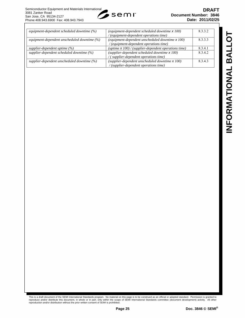
This is a draft document of the SEMI International Standards program. No material on this page is to be construed as an official or adopted standard. Permission is granted to reproduce and/or distribute this document, in whole or in part, only within the scope of SEMI International Standards committee (document development) activity. All other reproduction and/or distribution without the prior written consent of SEMI is prohibited.
Page 25 Doc. 3846 SEMI
Semiconductor Equipment and Materials International 3081 Zanker Road San Jose, CA 95134-2127 Phone:408.943.6900 Fax: 408.943.7943
INF
OR
MA
TIO
NA
L B
AL
LO
T
DRAFTDocument Number: 3846
Date: 2011/02/25
equipment-dependent scheduled downtime (%) (equipment-dependent scheduled downtime x 100) / (equipment-dependent operations time)
8.3.3.2
equipment-dependent unscheduled downtime (%) (equipment-dependent unscheduled downtime x 100) / (equipment-dependent operations time)
8.3.3.3
supplier-dependent uptime (%) (uptime x 100) / (supplier-dependent operations time) 8.3.4.1 supplier-dependent scheduled downtime (%) (supplier-dependent scheduled downtime x 100)
/ ( supplier-dependent operations time) 8.3.4.2
supplier-dependent unscheduled downtime (%) (supplier-dependent unscheduled downtime x 100) / (supplier-dependent operations time)
8.3.4.3

This is a draft document of the SEMI International Standards program. No material on this page is to be construed as an official or adopted standard. Permission is granted to reproduce and/or distribute this document, in whole or in part, only within the scope of SEMI International Standards committee (document development) activity. All other reproduction and/or distribution without the prior written consent of SEMI is prohibited.
Page 26 Doc. 3846 SEMI
Semiconductor Equipment and Materials International 3081 Zanker Road San Jose, CA 95134-2127 Phone:408.943.6900 Fax: 408.943.7943
INF
OR
MA
TIO
NA
L B
AL
LO
T
DRAFTDocument Number: 3846
Date: 2011/02/25
8.6.3 Maintainability Metrics
Group 1, for IPS and MP cluster tools, input to metrics is based on aggregate module performance in the numerator and aggregate module performance in the denominator.
Table 5 Maintainability Metrics Group 1
Metric Formula Section Reference
MTTPM — Mean time to (perform) preventive maintenance (PM)
(SDT preventive maintenance) /(# of PMs) 8.4.1.1
MTTR — Mean time to repair (UDT repair, equipment related + UDT repair, non-equipment related) / (# of equipment-related repair events + # of non-equipment-related repair events)
8.4.1.2
E-MTTR — Mean time to repair equipment-related failures
(UDT repair, equipment-related) / (# of equipment-related repair events)
8.4.1.3
MTOL — Mean time off-line (scheduled downtime + unscheduled downtime) / (# of continuous downtime events)
8.4.1.4
Group 2, for IPS and MP cluster tools, input to metrics is based on aggregate module performance in the numerator and non-aggregate equipment system performance in the denominator.
Table 6 Maintainability Metrics Group 2
Metric Formula Section Reference
TFR—Total failure rate (# of module-level failures) / (equipment system total time)
8.4.2.1
impairment time (%) (time when at least one module is in unscheduled down x 100) / ( equipment system total time)
8.4.2.2
8.6.4 Utilization Metrics
For all IPS and MP cluster tools, input to metrics is based on temporal mapped E10 states per Section 7.
Table 7 Utilization Metrics
Metric Formula Section Reference
total utilization(%) (productive time x 100) / (total time) 8.5.1 operational utilization(%) (productive time x 100) / (operations time) 8.5.2

This is a draft document of the SEMI International Standards program. No material on this page is to be construed as an official or adopted standard. Permission is granted to reproduce and/or distribute this document, in whole or in part, only within the scope of SEMI International Standards committee (document development) activity. All other reproduction and/or distribution without the prior written consent of SEMI is prohibited.
Page 27 Doc. 3846 SEMI
Semiconductor Equipment and Materials International 3081 Zanker Road San Jose, CA 95134-2127 Phone:408.943.6900 Fax: 408.943.7943
INF
OR
MA
TIO
NA
L B
AL
LO
T
DRAFTDocument Number: 3846
Date: 2011/02/25
9 MTBF Uncertainty Measurement
NOTE 20: For purposes of simplicity, this section refers to MTBF; however, substitutions can be made for the defined variations of MTBF/E-MTBF defined in (add table reference).
9.1 The measures of equipment reliability, availability, and maintainability defined in Section 7 and Section 8 are single value estimates. They do not indicate the uncertainty or precision of the estimate. Precision varies depending upon the number of failures observed and the amount of productive time contained within the observation period.
9.2 Precision is described by calculating a lower and upper confidence limit for the MTBF calculations and presenting this interval along with the MTBF point estimate.
9.3 These procedures assume that the failure rate is constant and the times between failures are independently distributed according to the exponential distribution. Therefore, there are no improvement or degradation trends and it is meaningful to calculate MTBF. Section 8 applies when the failure times indicate that a non-constant failure rate is present (for example, when there is reliability growth or degradation). Section 8 would typically apply during prototype reliability improvement testing.
9.4 Since MTTR distributions are unlikely to follow an exponential distribution assumption, applying these procedures to put confidence limits on MTTR would be inappropriate.
9.5 Note that all procedures and tables referred to in this section apply equally well to measuring the precision of estimates for similar metrics, where hours are replaced by cycles or units, for example. These procedures apply to E-MTBF or E-MCBF in the same way. It is also appropriate to combine data from identical equipment being used the same way, in order to improve the precision of MTBF estimates.
9.6 Calculation of Lower and Upper Confidence Limits — To obtain lower and upper MTBF limits, multiply the MTBF estimate by factors obtained by table look-up (Tables A1-1 and A1-2 in Appendix 1). For the case when there are zero failures during the measurement period, lower confidence limit factors for the MTBF are given in the first row of Table A1-1 (they multiply the amount of productive time that had no failures to obtain the desired MTBF lower limit). There is no upper limit estimate for performance when there are zero failures.
9.6.1 Calculation of the MTBF Lower Limit — Use Table A1-1 in Appendix 1 to obtain a kr;conf factor, where r is the number of failures observed during the measurement period and conf is the confidence level desired. The rows of Table A1-1 correspond to different values of r and the columns correspond to different values of conf. Confidence levels ranging from 80 percent to 95 percent are typical choices.
9.6.1.1 Since the equipment being measured has demonstrated (at a given confidence level) that it is at least as good as the MTBF lower limit, this lower limit is an important and useful performance statistic, and is often used contractually.
9.6.1.2 Note that the factors in Table A1-1 for 90% confidence are less than 0.5 until the number of failures equals or exceeds 4. This means that when the number of failures is under 4, the MTBF lower limit will be less than half the MTBF estimate, and confidence intervals will be wide. From the point of view of precision, it is advantageous to have had 4 or more failures.
9.6.1.3 Example: During a given calendar quarter, an equipment was productive for 1200 hours and had 6 failures. The MTBF estimate is 1200 / 6 = 200 hours. A 90 percent lower limit factor from Table A1-1 (corresponding to r = 6 failures) is 0.570. That means that 200 × 0.570 = 114.0 hours is a 90 percent lower confidence limit for the true equipment MTBF.
9.6.2 Calculation of the MTBF Upper Limit — Use Table A1-2 in Appendix 1 to obtain a kr;conf factor, where r is the number of failures observed during the measurement period and conf is the confidence level desired. The rows of Table A1-2 correspond to different values of r and the columns correspond to different values of conf. Confidence levels ranging from 80 percent to 95 percent are typical choices.
9.6.2.1 Example: During a given calendar quarter, an equipment was productive for 1200 hours and had 6 failures. The MTBF estimate is 1200 / 6 = 200 hours. A 90 percent upper limit factor from Table A1-2 (corresponding to r = 6 failures) is 1.904. That means that 200 × 1.904 = 380.8 hours is a 90 percent upper confidence limit for the true equipment MTBF.

This is a draft document of the SEMI International Standards program. No material on this page is to be construed as an official or adopted standard. Permission is granted to reproduce and/or distribute this document, in whole or in part, only within the scope of SEMI International Standards committee (document development) activity. All other reproduction and/or distribution without the prior written consent of SEMI is prohibited.
Page 28 Doc. 3846 SEMI
Semiconductor Equipment and Materials International 3081 Zanker Road San Jose, CA 95134-2127 Phone:408.943.6900 Fax: 408.943.7943
INF
OR
MA
TIO
NA
L B
AL
LO
T
DRAFTDocument Number: 3846
Date: 2011/02/25
9.6.3 Calculation of a Confidence Interval for the MTBF — Lower and upper 100 × (1 – /2) confidence limits for the MTBF can be combined to give a 100 × (1 – ) confidence interval. Here /2 is the chance of missing on either end of the interval. A 90 percent lower limit has an /2 = 0.1 chance of not being low enough to capture the true MTBF, and the same is true for a 90 percent upper limit. Therefore, a 90 percent lower limit and a 90 percent upper limit combine to give an 80 percent confidence interval. Similarly, a 95 percent lower limit and a 95 percent upper limit would combine to give a 90 percent confidence interval.
9.6.3.1 Example: During a calendar quarter, an equipment was productive for 1200 hours and had 6 failures. The MTBF estimate is 1200 / 6 = 200 hours. The 90 percent lower and upper limits are 114 and 380.8 respectively (see Sections 7.6.1 and 7.6.2). The interval (114, 380.8) is then an 80 percent confidence interval for the true equipment MTBF.
9.6.4 Calculation of the MTBF Lower Bound when there are Zero Failures — Use the first row of Table A1-1 (corresponding to r = 0) to obtain a k0;conf factor corresponding to the desired confidence level. Multiply the length of the measurement period by this factor to obtain the lower limit estimate.
9.6.4.1 Example: During a calendar quarter, an equipment was productive for 1200 hours and had zero failures. From Table A1-1, the 90% confidence level lower limit factor is 0.434. That means that 1200 × 0.434 = 520.8 hours, is a 90% lower confidence limit estimate for the true equipment MTBF.
9.6.5 Choosing a test length in order to be able to demonstrate a required MTBF at a given confidence, we first must pick a maximum number of failures, r, that can occur during the test period and still allow us to confirm a required MTBF objective at a given confidence level. Next, the length of test time needed can be calculated using the factors in Table A1-4 in Appendix 1. The required MTBF is multiplied by a factor based on r and the desired confidence level to obtain the total test time needed.
9.6.5.1 Note that minimum test times are obtained by allowing no failures. The cost, however, of using a minimum test length is to increase the possibility of an acceptable equipment failing the test by chance. As mentioned in the discussion in Section 6.2.1, it is advantageous to design a test that allows up to 4 failures, whenever possible.
9.6.5.2 Example: We would like to confirm an equipment MTBF of 400 hours at an 80% confidence level. We want to be able to pass a qualification test with 4 or less failures. We look up the appropriate factor from Table A1-4 and find 6.72. That means the length of test time required is 400 × 6.72 = 2688 hours. We can do this on one equipment or split the test time across multiple equipment. When we have accumulated 2688 hours and if 4 or less failures have occurred, the MTBF objective of 400 hours will have been confirmed at (at least) the 80% confidence level.

This is a draft document of the SEMI International Standards program. No material on this page is to be construed as an official or adopted standard. Permission is granted to reproduce and/or distribute this document, in whole or in part, only within the scope of SEMI International Standards committee (document development) activity. All other reproduction and/or distribution without the prior written consent of SEMI is prohibited.
Page 29 Doc. 3846 SEMI
Semiconductor Equipment and Materials International 3081 Zanker Road San Jose, CA 95134-2127 Phone:408.943.6900 Fax: 408.943.7943
INF
OR
MA
TIO
NA
L B
AL
LO
T
DRAFTDocument Number: 3846
Date: 2011/02/25
10 Reliability Growth or Degradation Measurement
NOTE 21: For purposes of simplicity, this section refers to MTBF; however, substitutions can be made for the defined variations of MTBF/E-MTBF defined in (add table reference).
10.1 The previous calculations are meaningful only when the MTBF (or MCBF) and E-MTBF (or E-MCBF) are constant over the observation period. If reliability is improving (typical during design verification and debug and also early life run-in) or if reliability is degrading (typical near the end of life for the piece of equipment, or if certain sub-assemblies have been over-stressed and are wearing out) then an overall MTBF calculation is inappropriate and misleading and other methods must be used. Exact time of failure recording is required in order to detect reliability improvement or reliability degradation trends, and to fit appropriate models.
10.2 Exact Time of Failure Recording — Clock times of failure must be converted to durations of cumulative productive time as measured from the initial productive use of the equipment (set as time 0). This is easily accomplished if total time is continuously monitored by duration within each of the six equipment states.
10.2.1 Example: A machine is intended for use during first shift operation five days a week. For simplicity, assume 100% productive utilization. After the first three weeks of use, it fails half-way through the day, and is not repaired until the start of the next day’s operation. No more failures occur before the end of the first four weeks of operation. The exact time of failure is 124 hours (three weeks of 5 × 8 = 40 hours per week plus half of an 8 hour day). If a second failure occurred two hours into the third day of the fifth week, the exact time of failure would be 174 hours.
10.3 Reliability Growth (Degradation) Models — A useful family of reliability growth (degradation) models was developed by the U.S. Army Materials Systems Analysis Activity. These AMSAA models are described in Appendix 2, along with a general test for reliability growth (degradation) trends. Exact time of failure data is needed to test for trends, fit an AMSAA model, and test the fit for adequacy. The failures used to fit the model must occur during productive time (other failures can occur, but these are not used to fit reliability models).

This is a draft document of the SEMI International Standards program. No material on this page is to be construed as an official or adopted standard. Permission is granted to reproduce and/or distribute this document, in whole or in part, only within the scope of SEMI International Standards committee (document development) activity. All other reproduction and/or distribution without the prior written consent of SEMI is prohibited.
Page 30 Doc. 3846 SEMI
Semiconductor Equipment and Materials International 3081 Zanker Road San Jose, CA 95134-2127 Phone:408.943.6900 Fax: 408.943.7943
INF
OR
MA
TIO
NA
L B
AL
LO
T
DRAFTDocument Number: 3846
Date: 2011/02/25
APPENDIX 1 CONFIDENCE BOUND FACTORS
NOTICE: This appendix was approved as an official part of SEMI E10 by full letter ballot procedure. It offers detailed information related to Section 9.
A1-1 Introduction
A1-1.1 Tables A1-1 and A1-2 contain factors that multiply an MTBF point estimate to obtain upper and lower confidence limits. Table A1-1 applies in the common case where the equipment is observed for a fixed period of time and the number of failures that will occur is unknown in advance (time censored data). The alternative is failure censored data, where the number of failures is specified in advance and the equipment is observed until that many failures occur. Table A1-3 contains lower limit factors for failure censored data. Since failure censored data rarely occurs in equipment reliability measurement, Table A1-3 is only included for completeness. The upper limit factors given in Table A1-2 apply to both kinds of censored data.
A1-1.2 Table A1-4 can be used to plan equipment assessment or qualification tests in order to be able to demonstrate a desired MTBF at a given confidence level. In order to use Table A1-4, you must first choose a maximum number of failures, r, you might observe during the test period and still be able to meet the required MTBF objective.
A1-1.3 For reference, here are the formulas for the lower and upper confidence limit factors for time censored data found in Tables A1-1 and A1-2:
MTBFLOWER
2r
X2r 2;12 × MTBFp
where r # of failures
MTBFUPPER
2rX
2r;2 × MTBFp
A1-1.4 In both cases, the confidence level is 100 × (1 – α) that the true MTBF is above MTBFLOWER and below MTBFUPPER and chi square distribution tables are used.
A1-1.5 For 0 fails, use:
MTBFLOWER productive time
-log e
A1-1.6 Factors to use when there are 0 failures based on this formula are given in the first row of Table A1-1.
A1-1.7 For failure censored data, MTBFUPPER is the same, but the lower limit factor in Table A1-3 is:
MTBFLOWER
2r
X2r ;1-2
× MTBFp

This is a draft document of the SEMI International Standards program. No material on this page is to be construed as an official or adopted standard. Permission is granted to reproduce and/or distribute this document, in whole or in part, only within the scope of SEMI International Standards committee (document development) activity. All other reproduction and/or distribution without the prior written consent of SEMI is prohibited.
Page 31 Doc. 3846 SEMI
Semiconductor Equipment and Materials International 3081 Zanker Road San Jose, CA 95134-2127 Phone:408.943.6900 Fax: 408.943.7943
INF
OR
MA
TIO
NA
L B
AL
LO
T
DRAFTDocument Number: 3846
Date: 2011/02/25
Table A1-1 Sided Lower Confidence Bound Factors for the MTBF (Time or Cycle Censored Data or Fixed Length Test)
Use for time or cycle censored data to multiply the MTBF or MCBF estimate to obtain a lower bound at the given confidence level.
For 0 failures, multiply the operating hours or cycles by the factor corresponding to the desired confidence level.
CONFIDENCE LEVEL
# FAILS r
60% 70% 80% 85% 90% 95% 97.5%
0 1.091 0.831 0.621 0.527 0.434 0.334 0.271
1 0.494 0.410 0.334 0.297 0.257 0.211 0.179
2 0.644 0.553 0.467 0.423 0.376 0.318 0.277
3 0.718 0.630 0.544 0.499 0.449 0.387 0.342
4 0.763 0.679 0.595 0.550 0.500 0.437 0.391
5 0.795 0.714 0.632 0.589 0.539 0.476 0.429
6 0.817 0.740 0.661 0.618 0.570 0.507 0.459
7 0.834 0.760 0.684 0.642 0.595 0.532 0.485
8 0.848 0.777 0.703 0.662 0.616 0.554 0.508
9 0.859 0.790 0.719 0.679 0.634 0.573 0.527
10 0.868 0.802 0.733 0.694 0.649 0.590 0.544
12 0.883 0.821 0.755 0.718 0.675 0.617 0.572
15 0.899 0.841 0.780 0.745 0.704 0.649 0.606
20 0.916 0.864 0.809 0.777 0.739 0.688 0.647
30 0.935 0.892 0.844 0.816 0.783 0.737 0.700
50 0.953 0.918 0.879 0.856 0.829 0.790 0.759
100 0.969 0.943 0.915 0.897 0.877 0.847 0.822
500 0.987 0.976 0.962 0.954 0.944 0.929 0.916
Table A1-2 Sided Upper Confidence Bound Factors for the MTBF
Use to multiply the MTBF estimate to obtain an upper bound at the given confidence level (time censored or failure censored data).
CONFIDENCE LEVEL
# FAILS r
60% 70% 80% 85% 90% 95% 97.5%
1 1.958 2.804 4.481 6.153 9.491 19.496 39.498
2 1.453 1.823 2.426 2.927 3.761 5.628 8.257
3 1.313 1.568 1.954 2.255 2.722 3.669 4.849
4 1.246 1.447 1.742 1.962 2.293 2.928 3.670
5 1.205 1.376 1.618 1.795 2.055 2.538 3.080
6 1.179 1.328 1.537 1.687 1.904 2.296 2.725
7 1.159 1.294 1.479 1.610 1.797 2.131 2.487
8 1.144 1.267 1.435 1.552 1.718 2.010 2.316
9 1.133 1.247 1.400 1.507 1.657 1.917 2.187
10 1.123 1.230 1.372 1.470 1.607 1.843 2.085
12 1.108 1.203 1.329 1.414 1.533 1.733 1.935
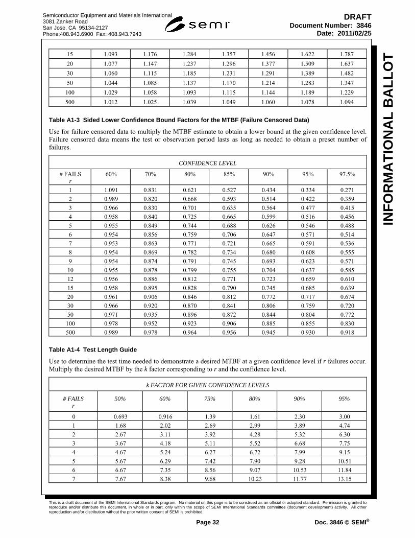
This is a draft document of the SEMI International Standards program. No material on this page is to be construed as an official or adopted standard. Permission is granted to reproduce and/or distribute this document, in whole or in part, only within the scope of SEMI International Standards committee (document development) activity. All other reproduction and/or distribution without the prior written consent of SEMI is prohibited.
Page 32 Doc. 3846 SEMI
Semiconductor Equipment and Materials International 3081 Zanker Road San Jose, CA 95134-2127 Phone:408.943.6900 Fax: 408.943.7943
INF
OR
MA
TIO
NA
L B
AL
LO
T
DRAFTDocument Number: 3846
Date: 2011/02/25
15 1.093 1.176 1.284 1.357 1.456 1.622 1.787
20 1.077 1.147 1.237 1.296 1.377 1.509 1.637
30 1.060 1.115 1.185 1.231 1.291 1.389 1.482
50 1.044 1.085 1.137 1.170 1.214 1.283 1.347
100 1.029 1.058 1.093 1.115 1.144 1.189 1.229
500 1.012 1.025 1.039 1.049 1.060 1.078 1.094
Table A1-3 Sided Lower Confidence Bound Factors for the MTBF (Failure Censored Data)
Use for failure censored data to multiply the MTBF estimate to obtain a lower bound at the given confidence level. Failure censored data means the test or observation period lasts as long as needed to obtain a preset number of failures.
CONFIDENCE LEVEL
# FAILS r
60% 70% 80% 85% 90% 95% 97.5%
1 1.091 0.831 0.621 0.527 0.434 0.334 0.271
2 0.989 0.820 0.668 0.593 0.514 0.422 0.359
3 0.966 0.830 0.701 0.635 0.564 0.477 0.415
4 0.958 0.840 0.725 0.665 0.599 0.516 0.456
5 0.955 0.849 0.744 0.688 0.626 0.546 0.488
6 0.954 0.856 0.759 0.706 0.647 0.571 0.514
7 0.953 0.863 0.771 0.721 0.665 0.591 0.536
8 0.954 0.869 0.782 0.734 0.680 0.608 0.555
9 0.954 0.874 0.791 0.745 0.693 0.623 0.571
10 0.955 0.878 0.799 0.755 0.704 0.637 0.585
12 0.956 0.886 0.812 0.771 0.723 0.659 0.610
15 0.958 0.895 0.828 0.790 0.745 0.685 0.639
20 0.961 0.906 0.846 0.812 0.772 0.717 0.674
30 0.966 0.920 0.870 0.841 0.806 0.759 0.720
50 0.971 0.935 0.896 0.872 0.844 0.804 0.772
100 0.978 0.952 0.923 0.906 0.885 0.855 0.830
500 0.989 0.978 0.964 0.956 0.945 0.930 0.918
Table A1-4 Test Length Guide
Use to determine the test time needed to demonstrate a desired MTBF at a given confidence level if r failures occur. Multiply the desired MTBF by the k factor corresponding to r and the confidence level.
k FACTOR FOR GIVEN CONFIDENCE LEVELS
# FAILS r
50% 60% 75% 80% 90% 95%
0 0.693 0.916 1.39 1.61 2.30 3.00
1 1.68 2.02 2.69 2.99 3.89 4.74
2 2.67 3.11 3.92 4.28 5.32 6.30
3 3.67 4.18 5.11 5.52 6.68 7.75
4 4.67 5.24 6.27 6.72 7.99 9.15
5 5.67 6.29 7.42 7.90 9.28 10.51
6 6.67 7.35 8.56 9.07 10.53 11.84
7 7.67 8.38 9.68 10.23 11.77 13.15

This is a draft document of the SEMI International Standards program. No material on this page is to be construed as an official or adopted standard. Permission is granted to reproduce and/or distribute this document, in whole or in part, only within the scope of SEMI International Standards committee (document development) activity. All other reproduction and/or distribution without the prior written consent of SEMI is prohibited.
Page 33 Doc. 3846 SEMI
Semiconductor Equipment and Materials International 3081 Zanker Road San Jose, CA 95134-2127 Phone:408.943.6900 Fax: 408.943.7943
INF
OR
MA
TIO
NA
L B
AL
LO
T
DRAFTDocument Number: 3846
Date: 2011/02/25
8 8.67 9.43 10.80 11.38 13.00 14.43
9 9.67 10.48 11.91 12.52 14.21 15.70
10 10.67 11.52 13.02 13.65 15.40 16.96
15 15.67 16.69 18.48 19.23 21.29 23.10
20 20.68 21.84 23.88 24.73 29.06 30.89

This is a draft document of the SEMI International Standards program. No material on this page is to be construed as an official or adopted standard. Permission is granted to reproduce and/or distribute this document, in whole or in part, only within the scope of SEMI International Standards committee (document development) activity. All other reproduction and/or distribution without the prior written consent of SEMI is prohibited.
Page 34 Doc. 3846 SEMI
Semiconductor Equipment and Materials International 3081 Zanker Road San Jose, CA 95134-2127 Phone:408.943.6900 Fax: 408.943.7943
INF
OR
MA
TIO
NA
L B
AL
LO
T
DRAFTDocument Number: 3846
Date: 2011/02/25
APPENDIX 2 RELIABILITY GROWTH OR DEGRADATION MODELS
NOTICE: This appendix was approved as an official part of SEMI E10 by full letter ballot procedure. It offers detailed information related to Section 8.
A2-1 Introduction
A2-1.1 If the times between failures (known as “interarrival times”) of a repairable system or piece of equipment are independent random times sampled from the same exponential distribution, then the (theoretical) rate of occurrence of failures (“ROCOF”) is a constant and the MTBF is just 1/. This situation is known in the reliability literature as a homogeneous Poisson process (HPP). An HPP assumption underlies the definition of MTBF given in Section 6, and the confidence limit factors described in Section 7 and Appendix 1. These concepts are described in detail in Ascher and Feingold [1] and Tobias and Trindade [2].
A2-1.2 If reliability is either improving or degrading with time, then the ROCOF is no longer a constant and a MTBF calculation will be misleading.
A2-1.3 This appendix contains a simple test for trend that may be applied if a time-varying ROCOF is suspected, as well as a description of a well known and powerful model that may be used when reliability improvement trends are evident in the equipment failure time data.
A2-2 Testing for Trends
A2-2.1 A non-parametric reverse arrangement test (RAT) devised by Kendall [3] and further developed into a table by Mann [4] will be described. Begin by writing the interarrival times in the order they occurred. For a period with r failures, these might be X1, X2, …, Xr. Starting from left to right, define a reversal as any instance in which a lesser value occurs before any subsequent greater value in the sequence. In other words, any time we have Xi < Xj and i < j, we count it as a reversal. For example, suppose a piece of equipment has r = 4 failures at 30, 160, 220, and 360 hours of productive time. The interarrival times are 30, 130, 60, and 140. The total number of reversals is 3 + 1 + 1 = 5.
A2-2.2 A larger than expected number of reversals indicates an improving trend; a smaller number of reversals than expected indicates a degradation trend.
A2-2.3 For r up to 12, use Table A2-1 below (adapted from [2]) to determine whether a given number of reversals, R, is statistically significant at the 100 × (1 – α) confidence level.
A2-2.4 For r greater than 12, approximate critical values for the number of reversals (based on Kendall’s normal approximation) can be calculated from:
R(r; 1-) zcritical(2r 5)(r 1)r
72
r(r 1)
4
1
2
Table A2-1 Critical Values Rr;1- the Number of Reversals for the Reverse Arrangement Test at a Given Confidence Level
Sample Size Single-Sided Lower Critical Value (Too Few Reversals Provide Evidence of Degradation)
Single-Sided Upper Critical Value (Too Many Reversals Provide Evidence of Improvement)
r 99% 95% 90% 90% 95% 99%
4 0 0 6 6
5 0 1 1 9 9 10
6 1 2 3 12 13 14
7 2 4 5 16 17 19
8 4 6 8 20 22 24
9 6 9 11 25 27 30
10 9 12 14 31 33 36
11 12 16 18 37 39 43

This is a draft document of the SEMI International Standards program. No material on this page is to be construed as an official or adopted standard. Permission is granted to reproduce and/or distribute this document, in whole or in part, only within the scope of SEMI International Standards committee (document development) activity. All other reproduction and/or distribution without the prior written consent of SEMI is prohibited.
Page 35 Doc. 3846 SEMI
Semiconductor Equipment and Materials International 3081 Zanker Road San Jose, CA 95134-2127 Phone:408.943.6900 Fax: 408.943.7943
INF
OR
MA
TIO
NA
L B
AL
LO
T
DRAFTDocument Number: 3846
Date: 2011/02/25
Sample Size Single-Sided Lower Critical Value (Too Few Reversals Provide Evidence of Degradation)
Single-Sided Upper Critical Value (Too Many Reversals Provide Evidence of Improvement)
12 16 20 23 43 46 50
A2-2.5 In this equation zcritical comes from the critical values of the standard normal distribution (for 90% significance, zcritical = 1.282, for 95% significance, zcritical = 1.645, and for 99% significance, zcritical = 2.33). The formula calculates the critical value for detecting an improvement trend. For degradation trends (a small number of reversals) use (r)(r 1)/2 minus Rr;1- as the critical value. Note that (r)(r 1)/2 just the total possible number of reversals when there are r failures.
A2-2.6 For example, with 17 failures, the formula for Rr;1-, using 95% significance, gives a critical number of reversals of R17,95 = 88. The maximum number of reversals is 17 × 16/2 = 136. That means that observing 88 or more reversals signals a likely improvement trend, while observing 136 88 = 48 or less reversals signals a likely degradation trend.
A2-2.7 The example given in the next section shows an application for the reverse arrangement test using Table A2-1.
A2-2.8 The AMSAA Reliability Growth Model: Assume the sequence of interarrival time indicates an improvement trend. This will typically be the case during reliability improvement testing, where failures are analyzed down to root causes and actions are taken to improve the equipment’s reliability. Duane [5] observed that a plot of tk/k versus tk, where tk is the system age at the time of kth failure, typically appears linear on log versus log graph paper. The slope of this line measures the rate of reliability growth. Typical empirical values of lie between 0.3 and 0.6. Crow [6] developed this empirical observation into the power relationship model used by the U.S. Army Materials Systems Analysis Activity (AMSAA model). This model has proved successful in a wide range of applications.
A2-2.9 The AMSAA model assumes that during reliability improvement testing the MTBF is improving with time and has an instantaneous value denoted by MTBFI (t). When the test ends at time T, the MTBF becomes a constant with the value MTBFI (T). An estimate of the MTBF after a test of T hours with r failures is given by:
MTBFI(T )
T
r× (1- ) (1)
A2-2.10 In this equation, is the reliability improvement (Duane) slope, is estimated by
1 -r 1
i=1r 1n
T
ti (2)
using the modified maximum likelihood estimates given by Crow [6]. Crow developed confidence limits for MTBFI
(T ) that are described in [2] and [6].
A2-2.11 Example: MTBFp is used for this example. During a calendar quarter an equipment has 550 hours of productive time. Eleven failures were recorded at the following points of productive time: 18, 20, 35, 41, 67, 180, 252, 287, 390, 410, and 511 hours. Determine whether there appears to be an improvement trend and use the AMSAA model to estimate the achieved MTBFI at the end of the quarter.
A2-2.12 Solution: The interarrival times are: 18, 2, 15, 6, 26, 113, 72, 35, 103, 20, and 101. The number of reversals is 7 + 9 + 7 + 7 + 5 + 0 + 2 + 2 + 0 + 1 = 40. Using Table A2-1, this is significant at greater than the 95% confidence level, indicating an improvement trend is likely. Figure A2-1 shows the Duane plot, which appears to show a linear improvement trend on log-log paper. The AMSAA model equations give an improvement slope estimate of 0.43 and an instantaneous MTBFP estimate at 550 hours of 87.2. Note that a standard calculation ignoring the improvement trend would yield an MTBFP estimate of 550/11 = 50, which is a 43% underestimate.
A2-2.13 Figure A2-2 summarizes the recommended procedure to follow when analyzing system or equipment reliability data, with appropriate references to SEMI E10 sections or appendices.

This is a draft document of the SEMI International Standards program. No material on this page is to be construed as an official or adopted standard. Permission is granted to reproduce and/or distribute this document, in whole or in part, only within the scope of SEMI International Standards committee (document development) activity. All other reproduction and/or distribution without the prior written consent of SEMI is prohibited.
Page 36 Doc. 3846 SEMI
Semiconductor Equipment and Materials International 3081 Zanker Road San Jose, CA 95134-2127 Phone:408.943.6900 Fax: 408.943.7943
INF
OR
MA
TIO
NA
L B
AL
LO
T
DRAFTDocument Number: 3846
Date: 2011/02/25
A2-3 References
1. Ascher, H. and H. Feingold, Repairable Systems Reliability, Marcel Dekkar, Inc., New York, 1984
2. Tobias, P.A. and D.C. Trindade, Applied Reliability, Second Edition, Van Nostrand Reinhold, Inc., New York, 1995
3. Kendall, M.G., “A New Measure of Rank Correlation”, Biometrika, 1938, volume 30, pages 81-93
4. Mann, H.B., “Nonparametric Test Against Trend” Econometrica, 1945, volume 13, pages 245-25
5. Duane, J.T., “Learning Curve Approach to Reliability Monitoring,” IEEE Transactions on Aerospace, 1964, volume 2, pages 563-566
6. Crow, L.H., “Reliability Analysis for Complex Repairable Systems,” Reliability and Biometry, F. Proschan and R.J., Serfling, eds., SIAM, Philadelphia, 1974; pp. 126-134
p
Figure A2-1
Duane Plot of CUM MTBF vs. Time
TrendNo Trend
Sections 8.1-8.3/Appendix 2
Estimate the achieved MTBF at the end of
the period
Sections 6.2.1-6.2.2
Use standard MTBF definition
Section 7.6/Appendix 1
Compute confidence bounds for MTBF
Analyze the data for trendsDuane Plots Trend Test
Section 8.3/Appendix 2
Fit AMSAA model
Figure A2-2
Flow Chart for Reliability Data Analysis

This is a draft document of the SEMI International Standards program. No material on this page is to be construed as an official or adopted standard. Permission is granted to reproduce and/or distribute this document, in whole or in part, only within the scope of SEMI International Standards committee (document development) activity. All other reproduction and/or distribution without the prior written consent of SEMI is prohibited.
Page 37 Doc. 3846 SEMI
Semiconductor Equipment and Materials International 3081 Zanker Road San Jose, CA 95134-2127 Phone:408.943.6900 Fax: 408.943.7943
INF
OR
MA
TIO
NA
L B
AL
LO
T
DRAFTDocument Number: 3846
Date: 2011/02/25
RELATED INFORMATION 1 MTBF, Renewal Processes, and the Exponential Distribution
R1-1 MTBF Metrics
The concept of MTBF arises from a branch of probability study called renewal theory. Each particular definition of MTBF is based on a model of equipment time that is a renewal process. Reliability processes in general have “up” and “down” segments in each cycle that together represent all equipment time of interest. A cycle in this process begins in an “up” segment with equipment in a presumably “good-as-new” state. The equipment continues in the “up” segment until it fails and transitions into the “down” segment. When repair is complete or the failure is rectified and equipment is effectively “renewed,” the equipment transitions into the “up” segment of a new cycle in the renewal process. The renewal process is defined such that cycles in the process may be assumed to be statistically comparable to one another. In simple reliability models, the time for the “up” segment is the time between failures, and the time for “down” segment is the time to repair.
UP DOWN
“Good-As-New” FailureEquipment“Renewed”
Reliability Renewal Cycle
A renewal cycle model provides significant analytic structure. In the case of a reliability renewal process with exponentially distributed up and down segments, the number of failures as a function of the cumulative time in up segments has the Poisson distribution. A system following the distribution is said to have time-average behavior such that the average of the system behavior over time is the same as the behavior of the “average cycle.” Hence, MTBF and MTTR are intended to describe the system at large, and not just a moment in time. Approaching such a system at random, the observer should expect to find the system up with probability equal to the ratio of up time (MTBF) to the average renewal cycle time (MTBF + MTTR). The genuine MTBF and MTTR values are assumed by the model to be inherent constants of the system rather than dynamic values, and measurement of these constants is an ongoing process that improves as more and more data is collected. MTBF estimates are generally considered invalid or misleading when observed over small time intervals.
Pr(Equipment Available) = (average time in “up” portion of cycle)
/ (average time for whole cycle) = MTBF / (MTBF + MTTR)
MTBF and MTTR are suitable as companion metrics in a reliability process when they have the same definition of failure events and have mutually exclusive time in the “up” and “down” segments of the cycle. Any two metrics that do not have these two properties are not suitable companion metrics and are incompatible within a coherent definition of a renewal process. In this specification, MTBFu and MFDu are suitable companion metrics, as are MTBFp and MFDp. The definitions of MTTR and E-MTTR in SEMI E10 have been enhanced for the case of multi-path cluster tools and are not necessarily suitable companion metrics to any variations of MTBF in SEMI E10.

This is a draft document of the SEMI International Standards program. No material on this page is to be construed as an official or adopted standard. Permission is granted to reproduce and/or distribute this document, in whole or in part, only within the scope of SEMI International Standards committee (document development) activity. All other reproduction and/or distribution without the prior written consent of SEMI is prohibited.
Page 38 Doc. 3846 SEMI
Semiconductor Equipment and Materials International 3081 Zanker Road San Jose, CA 95134-2127 Phone:408.943.6900 Fax: 408.943.7943
INF
OR
MA
TIO
NA
L B
AL
LO
T
DRAFTDocument Number: 3846
Date: 2011/02/25
The collection of up and down segments of a particular renewal process need not represent 24 hours by 7 days per week. Considering MTBFp, the “up” portion of the renewal cycle is productive time only and the “down” portion is the failure time, repair time, and subsequent requalification time arising from only the productive state. For MTBFp, the up portion specifically excludes engineering time and failures from engineering time, implicitly expecting the likelihood of failures to be different when equipment engineers are “pushing the envelope” of that equipment. Also, the down portion specifically excludes preventive maintenance and other general maintenance issues covered under the scheduled downtime state. Non-scheduled time is neither up nor down and is entirely excluded from consideration.
The meaning of the metric MTBFp then is literally the productive time of the average renewal cycle as defined above. Because the exponential distribution is assumed (implicitly) in SEMI E10, it turns out that this value may be estimated as the cumulative productive time divided by the cumulative failures from productive time. The reciprocal of MTBFp expresses how often should similar equipment systems fail as a result of usage strictly in productive time.
R1-2 Exponential Distribution and MTBF
MTBF in SEMI E10 implicitly assumes an exponential distribution of the time between failures. MTBF is not only the expected value of this distribution. It is also the solitary parameter of this distribution.
PDF f(x, MTBF) = (1/MTBF) x exp(-x / MTBF), x>= 0 CDF f(x, MTBF) = 1 – exp(-x / MTBF), x>= 0 E(f(x, MTBF)) = MTBF StDev(f(x, MTBF)) = MTBF
The probability that a system will remain up for a period longer than t is given by:
Pr(X > t) = exp(-t / MTBF)
The probability that a system will remain up an additional time s, having already been up t, demonstrates the memoryless property that is exclusive to the exponential distribution.
Pr(X> t+s | X> t) = Pr(X>t + s) / Pr(X > t)
= exp(-(t + s) / MTBF) / exp(-t / MTBF) = exp(-(t + s - t) / MTBF) = exp(-s / MTBF) = Pr(X>s)
In this case, the distribution of the additional time s is the same as for a new unit and is independent of the previous time t. This defies the expectation that a system is more likely to fail the longer it has been up. Qualitatively, the memoryless property says that a system’s resistance to failure is not a function of its age or wear. To the extent that the analysts believe the exponential distribution to be representative of times between failures and that the MTBF is the accurate parameter of that distribution, measures of risk for specific scenarios may be estimated. The table below shows the probability of survival time as a percentage of the MTBF. For example, if MTBF = 500 hours, the probability of survival for 1000 hours (200% of MTBF) is 13.5%.

This is a draft document of the SEMI International Standards program. No material on this page is to be construed as an official or adopted standard. Permission is granted to reproduce and/or distribute this document, in whole or in part, only within the scope of SEMI International Standards committee (document development) activity. All other reproduction and/or distribution without the prior written consent of SEMI is prohibited.
Page 39 Doc. 3846 SEMI
Semiconductor Equipment and Materials International 3081 Zanker Road San Jose, CA 95134-2127 Phone:408.943.6900 Fax: 408.943.7943
INF
OR
MA
TIO
NA
L B
AL
LO
T
DRAFTDocument Number: 3846
Date: 2011/02/25
Table R1-1 Exponential Distribution Probability of Survival Time as a Percentage of MTBF
Survival Time (% of MTBF)
25% 50% 75% 100% 150% 200% 300% 400% 500%
Probability 77.9% 60.7% 47.2% 36.8% 22.3% 13.5% 5.0% 1.8% 0.7%
NOTICE: SEMI makes no warranties or representations as to the suitability of the standards set forth herein for any particular application. The determination of the suitability of the standard is solely the responsibility of the user. Users are cautioned to refer to manufacturer’s instructions, product labels, product data sheets, and other relevant literature respecting any materials mentioned herein. These standards are subject to change without notice.
The user’s attention is called to the possibility that compliance with this standard may require use of copyrighted material or of an invention covered by patent rights. By publication of this standard, SEMI takes no position respecting the validity of any patent rights or copyrights asserted in connection with any item mentioned in this standard. Users of this standard are expressly advised that determination of any such patent rights or copyrights, and the risk of infringement of such rights, are entirely their own responsibility.