
Background and Project Description · Background and Project Description DESCRIPTION OF DEVELOPMENT...
25
Background and Project Description Chapter 05: Description of Development
Transcript of Background and Project Description · Background and Project Description DESCRIPTION OF DEVELOPMENT...

Background and Project DescriptionChapter 05: Description of Development

Background and Project Description DESCRIPTION OF DEVELOPMENT
INCH CAPE OFFSHORE LIMITED ONSHORE ENVIRONMENTAL STATEMENT i
Chapter
05
Contents
Contents ......................................................................................................................................... i
List of Figures .................................................................................................................................. ii
Abbreviations and Acronyms ......................................................................................................... iii
5.1 Introduction ................................................................................................................... 1
5.2 Project Elements ............................................................................................................ 1
5.3 Onshore Transmission Works – Construction Phase ........................................................ 2
5.3.1 Landfall .................................................................................................................................. 2
5.3.2 Cable Transition Pit(s) ........................................................................................................... 5
5.3.3 Onshore Export Cable Corridor between the Cable Transition Pits and the Onshore Substation ............................................................................................................................. 6
5.3.4 Jointing Pits ........................................................................................................................... 9
5.3.5 Onshore Substation Site ........................................................................................................ 9
5.3.6 Onshore Export Cable Corridor between the Onshore Substation and the grid connection point .................................................................................................................................... 14
5.3.7 Construction Compound Description of Works .................................................................. 15
5.3.8 Application Site Access ........................................................................................................ 16
5.3.9 Enabling Works .................................................................................................................... 17
5.3.10 Construction Working Hours ............................................................................................... 17
5.3.11 Construction Environmental Management Plan and Community Liaison .......................... 17
5.3.12 Construction Programme .................................................................................................... 19
5.4 Onshore Transmission Works – Operational Phase ........................................................ 19
5.5 Onshore Transmission Works – Decommissioning Phase ............................................... 20
Background and Project DescriptionDESCRIPTION OF DEVELOPMENT
Chapter
05
INCH CAPE OFFSHORE LIMITED ONSHORE ENVIRONMENTAL STATEMENT
i

Background and Project Description DESCRIPTION OF DEVELOPMENT
INCH CAPE OFFSHORE LIMITED ONSHORE ENVIRONMENTAL STATEMENT ii
Chapter
05
List of Figures
Figure 5.1: Schematic Representation of OnTW and Offshore Wind Farm ........................................... 2 Figure 5.2: Offshore Three Core Cable (Source: JDR Cable Systems Ltd) .............................................. 3 Figure 5.3: Example of Onshore Single Core Cable (Source: ABB) ......................................................... 3 Figure 5.4: Cable Installation at a Shore Landing Point (Source: SMD) ................................................. 4 Figure 5.5: Stages of Horizontal Directional Drilling (Source: Stockton Drilling) ................................... 5 Figure 5.6: Transition Pit Detail ............................................................................................................. 6 Figure 5.7: Onshore Cable Trench for Trefoil Layout ............................................................................. 6 Figure 5.8: Onshore Cable Trench (Source: Balfour Beatty) .................................................................. 7 Figure 5.9: Onshore Cable Formations Flat or Trefoil ............................................................................ 7 Figure 5.10: Indicative Onshore Export Cable Trenching Corridor at B1348 ......................................... 8 Figure 5.11: Indicative 3D Representation of the Onshore Substation Layout ................................... 10 Figure 5.12: Example of an Indoor GIS substation from Inside ........................................................... 12 Figure 5.13: Example of Auxiliary Transformer ................................................................................... 13 Figure 5.14: Example of Shunt Reactor ............................................................................................... 13 Figure 5.15: Example of STATCOM ...................................................................................................... 13 Figure 5.16: Example of Transformer Area .......................................................................................... 14 Figure 5.17: Temporary Construction Compound ............................................................................... 16 Figure 5.18: Programme of Works ....................................................................................................... 19
Background and Project DescriptionDESCRIPTION OF DEVELOPMENT
Chapter
05
INCH CAPE OFFSHORE LIMITED ONSHORE ENVIRONMENTAL STATEMENT
ii

Background and Project Description DESCRIPTION OF DEVELOPMENT
INCH CAPE OFFSHORE LIMITED ONSHORE ENVIRONMENTAL STATEMENT iii
Chapter
05
Abbreviations and Acronyms
AC Alternating Current
CEMP Construction Environmental Management Plan
EcOW Ecological Clerk of Works
ELC East Lothian Council
EIA Environmental Impact Assessment
GIS Gas Insulated Switchgear
HDD Horizontal Directional Drilling
ICOL Inch Cape Offshore Limited
MHWS Mean High Water Springs
MLWS Mean Low Water Springs
NETS National Electricity Transmission System
OnTW Onshore Transmission Works
PPP Planning Permission in Principle
STATCOM Static Synchronous Compensator
XLPE Cross-‐Linked Polyethylene
Background and Project DescriptionDESCRIPTION OF DEVELOPMENT
Chapter
05
INCH CAPE OFFSHORE LIMITED ONSHORE ENVIRONMENTAL STATEMENT
iii
Background and Project Description DESCRIPTION OF DEVELOPMENT
INCH CAPE OFFSHORE LIMITED ONSHORE ENVIRONMENTAL STATEMENT
Chapter
05
1 of 20
5 Description of Development
5.1 Introduction
1 This chapter of the Environmental Statement provides a description of the Inch Cape Onshore Transmission Works (OnTW) proposed to connect the Inch Cape Offshore Wind Farm to the existing onshore National Electricity Transmission System (NETS).
2 As Inch Cape Offshore Limited (ICOL) is applying for Planning Permission in Principle (PPP) only, it is not possible at this stage to provide a detailed description of all elements of the OnTW e.g. precise building dimensions, colours, footprints etc. The description of development presented in this chapter provides as much detail as possible about the OnTW, while leaving matters of detail to a further approval process, should PPP be granted. To ensure the Environmental Impact Assessment (EIA) is carried out on a worst case scenario, certain assumptions about the OnTW have been built into the assessment process, as detailed in the following sections, thus ensuring the EIA is based around pre-‐defined parameters for all elements of the OnTW.
3 A description of the Application Site is included in Section 1.3.3.
5.2 Project Elements
4 The OnTW comprises of the following primary elements:
• Landfall where up to four Offshore Export Cables from the Inch Cape Offshore Wind Farm will be brought ashore and will run underground to the Cable Transition Pits (see Section 5.3.1);
• Cable Transition Pits where up to four Offshore Export Cables interface with up to four sets of Onshore Export Cables (see Section 5.3.2);
• Onshore Export Cable Corridor from the Cable Transition Pits to the Onshore Substation: which will contain up to four trenches for running the underground Onshore Export Cables between the Cable Transition Pits and the Onshore Substation (see Section 5.3.3);
• Up to four jointing pits which are required to join sections of Onshore Export Cables together (see Section 5.3.4);
• Onshore Substation: which is required to process the electricity from the Offshore Wind Farm and to comply with the requirements of the NETS (see Section 5.3.5);
• Onshore Export Cable Corridor from the Onshore Substation to the grid connection point: which will contain up to two trenches for running the underground Onshore Export Cables between the Onshore Substation and the grid connection point (see Section 5.3.6); and
• Application Site Access will be via an upgrade to the existing access from the B6371 (see Section 5.3.7).
Background and Project DescriptionDESCRIPTION OF DEVELOPMENT
Chapter
05
INCH CAPE OFFSHORE LIMITED ONSHORE ENVIRONMENTAL STATEMENT
1 of 20
Background and Project Description DESCRIPTION OF DEVELOPMENT
INCH CAPE OFFSHORE LIMITED ONSHORE ENVIRONMENTAL STATEMENT
Chapter
05
2 of 20
5 The OnTW will also comprise of other elements including mitigation measures. Embedded mitigation, for the OnTW, includes all mitigation assumed to be in place during the relevant phases of construction, operation and decommissioning of the OnTW. Embedded mitigation is that which has been recognised as having benefits in reducing impact significance, and is generally regarded as industry standard or best practice. Specific mitigation is included in each technical chapter.
6 The locations of these elements described above are shown in Figure 1.4 for indicative purposes only. The final locations will be determined on the basis of a further approval process, should PPP be granted.
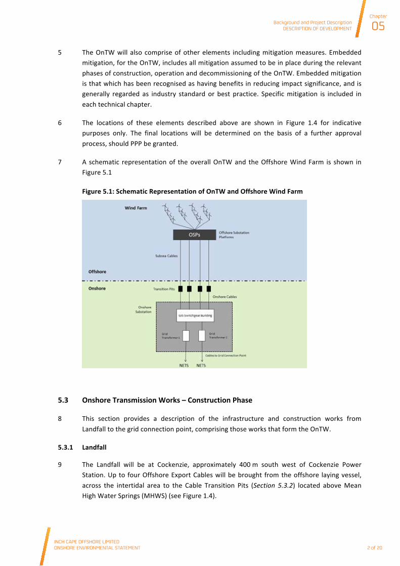
7 A schematic representation of the overall OnTW and the Offshore Wind Farm is shown in Figure 5.1
Figure 5.1: Schematic Representation of OnTW and Offshore Wind Farm
5.3 Onshore Transmission Works – Construction Phase
8 This section provides a description of the infrastructure and construction works from Landfall to the grid connection point, comprising those works that form the OnTW.
5.3.1 Landfall
9 The Landfall will be at Cockenzie, approximately 400 m south west of Cockenzie Power Station. Up to four Offshore Export Cables will be brought from the offshore laying vessel, across the intertidal area to the Cable Transition Pits (Section 5.3.2) located above Mean High Water Springs (MHWS) (see Figure 1.4).
Background and Project DescriptionDESCRIPTION OF DEVELOPMENT
Chapter
05
INCH CAPE OFFSHORE LIMITED ONSHORE ENVIRONMENTAL STATEMENT
2 of 20
Background and Project Description DESCRIPTION OF DEVELOPMENT
INCH CAPE OFFSHORE LIMITED ONSHORE ENVIRONMENTAL STATEMENT
Chapter
05
3 of 20
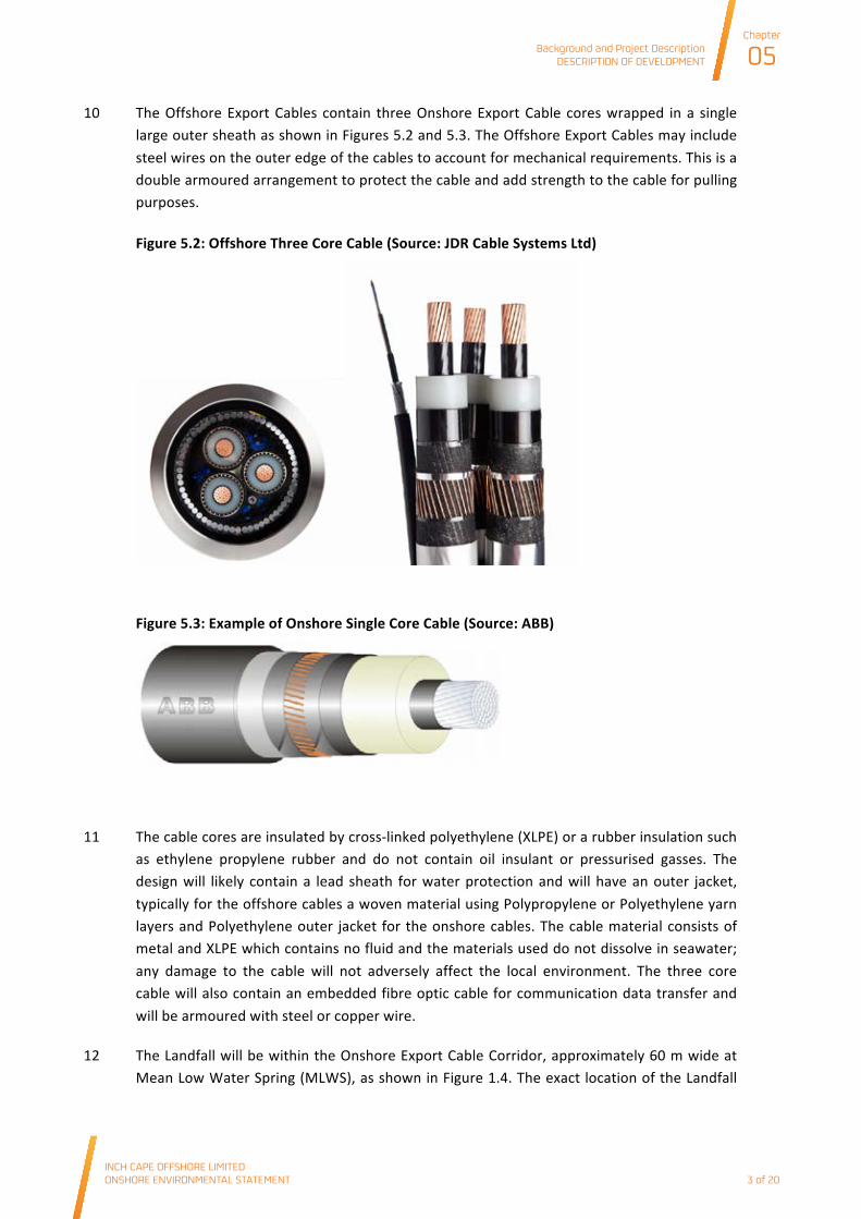
10 The Offshore Export Cables contain three Onshore Export Cable cores wrapped in a single large outer sheath as shown in Figures 5.2 and 5.3. The Offshore Export Cables may include steel wires on the outer edge of the cables to account for mechanical requirements. This is a double armoured arrangement to protect the cable and add strength to the cable for pulling purposes.
Figure 5.2: Offshore Three Core Cable (Source: JDR Cable Systems Ltd)
Figure 5.3: Example of Onshore Single Core Cable (Source: ABB)
11 The cable cores are insulated by cross-‐linked polyethylene (XLPE) or a rubber insulation such as ethylene propylene rubber and do not contain oil insulant or pressurised gasses. The design will likely contain a lead sheath for water protection and will have an outer jacket, typically for the offshore cables a woven material using Polypropylene or Polyethylene yarn layers and Polyethylene outer jacket for the onshore cables. The cable material consists of metal and XLPE which contains no fluid and the materials used do not dissolve in seawater; any damage to the cable will not adversely affect the local environment. The three core cable will also contain an embedded fibre optic cable for communication data transfer and will be armoured with steel or copper wire.
12 The Landfall will be within the Onshore Export Cable Corridor, approximately 60 m wide at Mean Low Water Spring (MLWS), as shown in Figure 1.4. The exact location of the Landfall
Background and Project DescriptionDESCRIPTION OF DEVELOPMENT
Chapter
05
INCH CAPE OFFSHORE LIMITED ONSHORE ENVIRONMENTAL STATEMENT
3 of 20
Background and Project Description DESCRIPTION OF DEVELOPMENT
INCH CAPE OFFSHORE LIMITED ONSHORE ENVIRONMENTAL STATEMENT
Chapter
05
4 of 20
within the Onshore Export Cable Corridor and the method for landing the cables will be established following the detailed investigation of environmental and technical factors.
13 During these works ICOL commit to maintaining access to the Prestonpans Yachting and Boating Club, located adjacent to the Landfall, at all times.
14 There are two main options for landing cables, either open cut trenching or horizontal directional drilling (HDD).
Open Cut Trenching
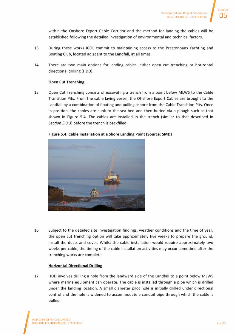
15 Open Cut Trenching consists of excavating a trench from a point below MLWS to the Cable Transition Pits. From the cable laying vessel, the Offshore Export Cables are brought to the Landfall by a combination of floating and pulling ashore from the Cable Transition Pits. Once in position, the cables are sunk to the sea bed and then buried via a plough such as that shown in Figure 5.4. The cables are installed in the trench (similar to that described in Section 5.3.3) before the trench is backfilled.
Figure 5.4: Cable Installation at a Shore Landing Point (Source: SMD)
16 Subject to the detailed site investigation findings, weather conditions and the time of year, the open cut trenching option will take approximately five weeks to prepare the ground, install the ducts and cover. Whilst the cable installation would require approximately two weeks per cable, the timing of the cable installation activities may occur sometime after the trenching works are complete.
Horizontal Directional Drilling
17 HDD involves drilling a hole from the landward side of the Landfall to a point below MLWS where marine equipment can operate. The cable is installed through a pipe which is drilled under the landing location. A small diameter pilot hole is initially drilled under directional control and the hole is widened to accommodate a conduit pipe through which the cable is pulled.
Background and Project DescriptionDESCRIPTION OF DEVELOPMENT
Chapter
05
INCH CAPE OFFSHORE LIMITED ONSHORE ENVIRONMENTAL STATEMENT
4 of 20
Background and Project Description DESCRIPTION OF DEVELOPMENT
INCH CAPE OFFSHORE LIMITED ONSHORE ENVIRONMENTAL STATEMENT
Chapter
05
5 of 20
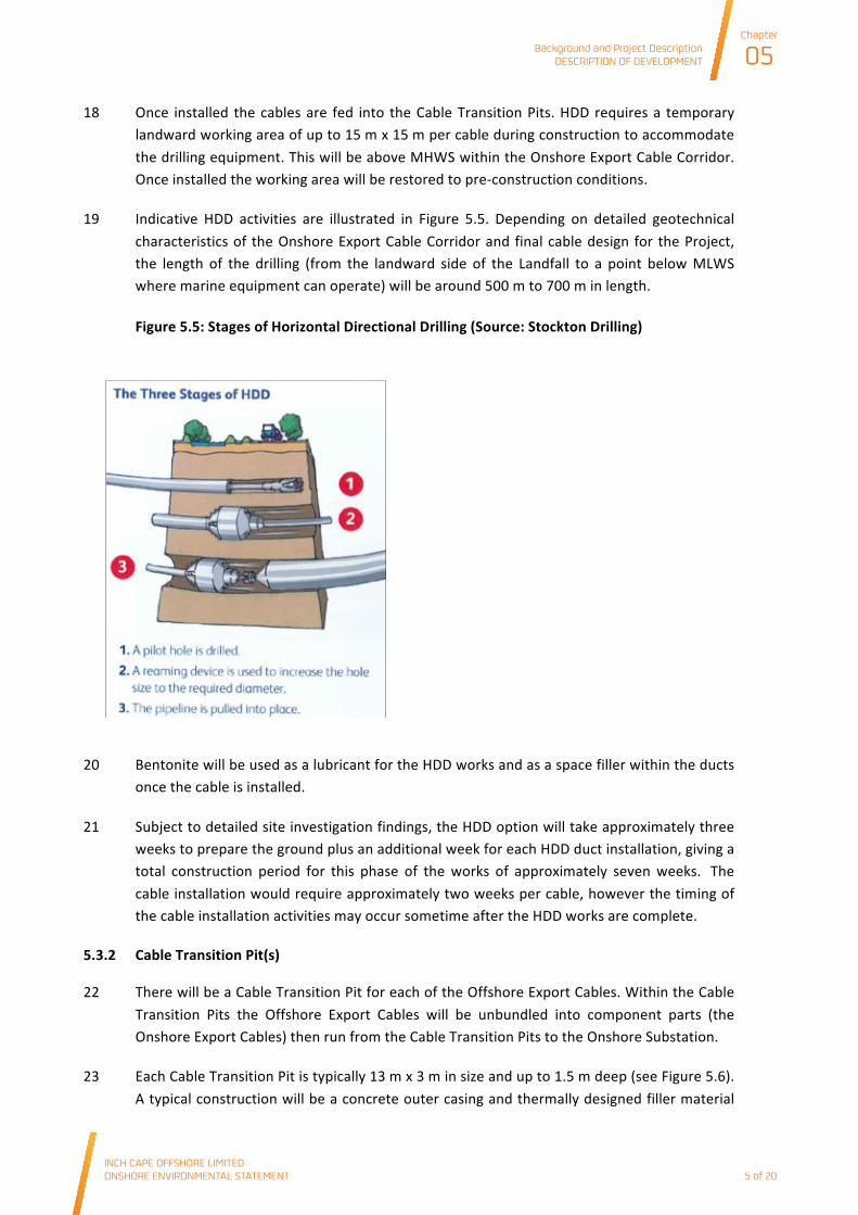
18 Once installed the cables are fed into the Cable Transition Pits. HDD requires a temporary landward working area of up to 15 m x 15 m per cable during construction to accommodate the drilling equipment. This will be above MHWS within the Onshore Export Cable Corridor. Once installed the working area will be restored to pre-‐construction conditions.
19 Indicative HDD activities are illustrated in Figure 5.5. Depending on detailed geotechnical characteristics of the Onshore Export Cable Corridor and final cable design for the Project, the length of the drilling (from the landward side of the Landfall to a point below MLWS where marine equipment can operate) will be around 500 m to 700 m in length.
Figure 5.5: Stages of Horizontal Directional Drilling (Source: Stockton Drilling)
20 Bentonite will be used as a lubricant for the HDD works and as a space filler within the ducts once the cable is installed.
21 Subject to detailed site investigation findings, the HDD option will take approximately three weeks to prepare the ground plus an additional week for each HDD duct installation, giving a total construction period for this phase of the works of approximately seven weeks. The cable installation would require approximately two weeks per cable, however the timing of the cable installation activities may occur sometime after the HDD works are complete.
5.3.2 Cable Transition Pit(s)
22 There will be a Cable Transition Pit for each of the Offshore Export Cables. Within the Cable Transition Pits the Offshore Export Cables will be unbundled into component parts (the Onshore Export Cables) then run from the Cable Transition Pits to the Onshore Substation.
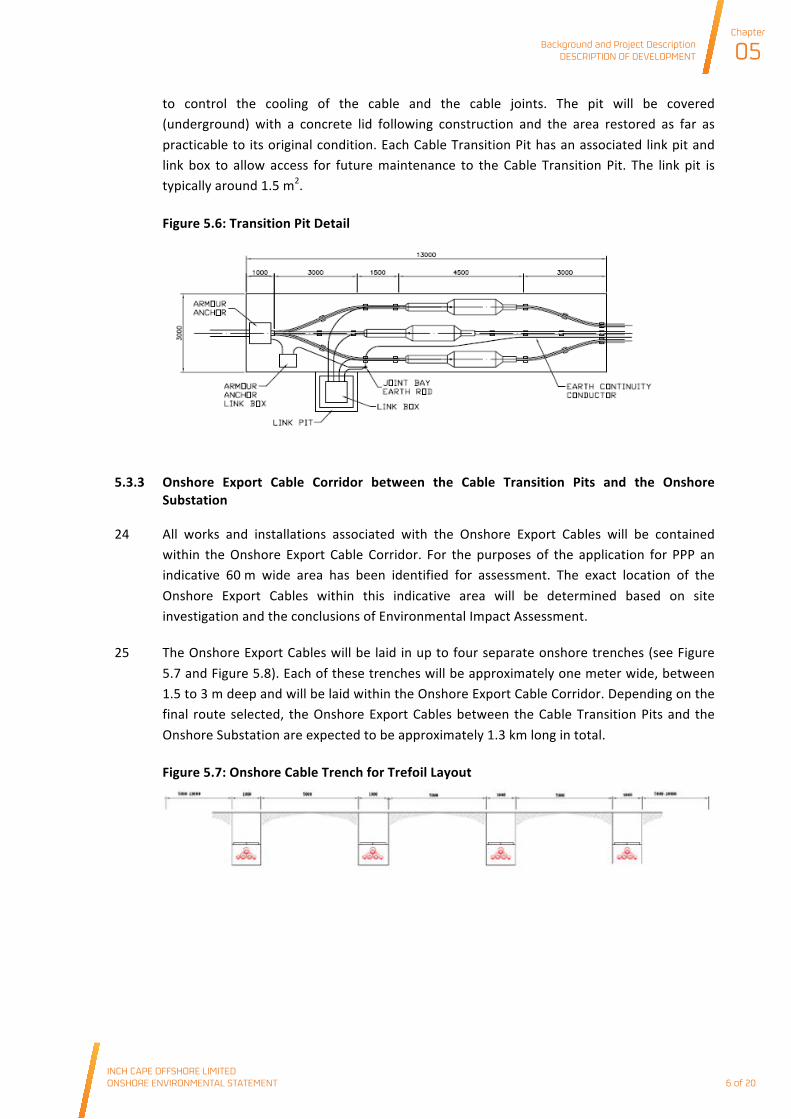
23 Each Cable Transition Pit is typically 13 m x 3 m in size and up to 1.5 m deep (see Figure 5.6). A typical construction will be a concrete outer casing and thermally designed filler material
Background and Project DescriptionDESCRIPTION OF DEVELOPMENT
Chapter
05
INCH CAPE OFFSHORE LIMITED ONSHORE ENVIRONMENTAL STATEMENT
5 of 20
Background and Project Description DESCRIPTION OF DEVELOPMENT
INCH CAPE OFFSHORE LIMITED ONSHORE ENVIRONMENTAL STATEMENT
Chapter
05
6 of 20
to control the cooling of the cable and the cable joints. The pit will be covered (underground) with a concrete lid following construction and the area restored as far as practicable to its original condition. Each Cable Transition Pit has an associated link pit and link box to allow access for future maintenance to the Cable Transition Pit. The link pit is typically around 1.5 m2.
Figure 5.6: Transition Pit Detail
5.3.3 Onshore Export Cable Corridor between the Cable Transition Pits and the Onshore Substation
24 All works and installations associated with the Onshore Export Cables will be contained within the Onshore Export Cable Corridor. For the purposes of the application for PPP an indicative 60 m wide area has been identified for assessment. The exact location of the Onshore Export Cables within this indicative area will be determined based on site investigation and the conclusions of Environmental Impact Assessment.
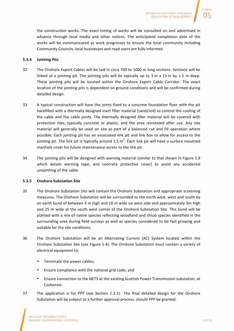
25 The Onshore Export Cables will be laid in up to four separate onshore trenches (see Figure 5.7 and Figure 5.8). Each of these trenches will be approximately one meter wide, between 1.5 to 3 m deep and will be laid within the Onshore Export Cable Corridor. Depending on the final route selected, the Onshore Export Cables between the Cable Transition Pits and the Onshore Substation are expected to be approximately 1.3 km long in total.
Figure 5.7: Onshore Cable Trench for Trefoil Layout
Background and Project DescriptionDESCRIPTION OF DEVELOPMENT
Chapter
05
INCH CAPE OFFSHORE LIMITED ONSHORE ENVIRONMENTAL STATEMENT
6 of 20

Background and Project Description DESCRIPTION OF DEVELOPMENT
INCH CAPE OFFSHORE LIMITED ONSHORE ENVIRONMENTAL STATEMENT
Chapter
05
7 of 20
Figure 5.8: Onshore Cable Trench (Source: Balfour Beatty)
26 Onshore cabling is typically installed in either a flat or trefoil arrangement as shown in Figure 5.9.
Figure 5.9: Onshore Cable Formations Flat or Trefoil
27 The Onshore Export Cables will generally be installed using surface cut trenching which will require temporary disturbance of the Onshore Export Cable Corridor. The Onshore Export Cables will be surrounded by a fine sand, or cement bound sand or similar (i.e. thermal backfill). Once installed the trench will be backfilled and the surface restored as far as practicable to the original condition or a condition as agreed through consultation. All temporary areas will be reinstated after use and any site material will generally be used on site as part of a balanced cut and fill operation where possible.
28 The Onshore Export Cable installation rate including trench digging, cable laying and backfilling the trench, will be around 30 -‐ 45 m/day. It is expected that the installation between the Cable Transition Pits and the Onshore Substation will require approximately between 30 and 50 days per cable.
29 Some sections of the Onshore Export Cable route, such as the crossing of the B1348 may require a trench or HDD.
30 If trenching is technically feasible, it is likely that a trench of up to 12 m wide will be created through the B1348, immediately east of the intersection with Nethershot Road (see Figure
Background and Project DescriptionDESCRIPTION OF DEVELOPMENT
Chapter
05
INCH CAPE OFFSHORE LIMITED ONSHORE ENVIRONMENTAL STATEMENT
7 of 20

Background and Project Description DESCRIPTION OF DEVELOPMENT
INCH CAPE OFFSHORE LIMITED ONSHORE ENVIRONMENTAL STATEMENT
Chapter
05
8 of 20
5.10). These works will take between 4 to 12 weeks depending on the existing services in the road and would be carried out in consultation with ELC, local communities and other stakeholders and avoid complete road closure. A local traffic management scheme will be designed in consultation with ELC, Transport Scotland, the local community including Community Councils and local businesses. The road will be restored to an agreed specification with the ELC’s Roads Authority. All relevant discussions with ELC, Transport Scotland, the local community including Community Councils and local businesses will take place prior to the commencement of any works to ensure appropriate measures are put in place to minimise disruption to road users, the local community and local businesses during the construction works. The exact timing of works will be consulted on and advertised in advance through local media and other notices. The anticipated completion date of the works will be communicated as work progresses to ensure the local community including Community Councils, local businesses and road users are fully informed.
Figure 5.10: Indicative Onshore Export Cable Trenching Corridor at B1348
31 If HDD is technically feasible, there will be no road closure. HDD will require an excavated area either side of the road approximately 3.5 m deep and 10 m x 12 m in footprint. Following completion of the work the area will be restored to its original condition as far as practicably possible. All relevant discussions with ELC, Transport Scotland, the local community including Community Councils and local businesses will take place prior to the commencement of any works to ensure appropriate measures are put in place to minimise disruption to road users, the local community and local businesses during
Background and Project DescriptionDESCRIPTION OF DEVELOPMENT
Chapter
05
INCH CAPE OFFSHORE LIMITED ONSHORE ENVIRONMENTAL STATEMENT
8 of 20
Background and Project Description DESCRIPTION OF DEVELOPMENT
INCH CAPE OFFSHORE LIMITED ONSHORE ENVIRONMENTAL STATEMENT
Chapter
05
9 of 20
the construction works. The exact timing of works will be consulted on and advertised in advance through local media and other notices. The anticipated completion date of the works will be communicated as work progresses to ensure the local community including Community Councils, local businesses and road users are fully informed.
5.3.4 Jointing Pits
32 The Onshore Export Cables will be laid in circa 700 to 1000 m long sections. Sections will be linked at a jointing pit. The jointing pits will be typically up to 3 m x 13 m by 1.5 m deep. These jointing pits will be located within the Onshore Export Cable Corridor. The exact location of the jointing pits is dependent on ground conditions and will be confirmed during detailed design.
33 A typical construction will have the joints fixed to a concrete foundation floor with the pit backfilled with a thermally designed inert filler material (sand/soil) to control the cooling of the cable and the cable joints. The thermally designed filler material will be covered with protection tiles, typically concrete or plastic, and the area reinstated after use. Any site material will generally be used on site as part of a balanced cut and fill operation where possible. Each jointing pit has an associated link pit and link box to allow for access to the jointing pit. The link pit is typically around 1.5 m2. Each link pit will have a surface mounted manhole cover for future maintenance access to the link pit.
34 The jointing pits will be designed with warning material (similar to that shown in Figure 5.9 which details warning tape, and concrete protective cover) to avoid any accidental unearthing of the cable.
5.3.5 Onshore Substation Site
35 The Onshore Substation Site will contain the Onshore Substation and appropriate screening measures. The Onshore Substation will be surrounded to the north west, west and south by an earth bund of between 4 m high and 10 m wide on west side and approximately 3m high and 25 m wide at the south west corner of the Onshore Substation Site. This bund will be planted with a mix of native species reflecting woodland and shrub species identified in the surrounding area during field surveys as well as species considered to be fast growing and suitable for the site conditions.
36 The Onshore Substation will be an Alternating Current (AC) System located within the Onshore Substation Site (see Figure 1.4). The Onshore Substation must contain a variety of electrical equipment to:
• Terminate the power cables;
• Ensure compliance with the national grid code; and
• Ensure connection to the NETS at the existing Scottish Power Transmission substation, at Cockenzie.
37 The application is for PPP (see Section 1.3.1). The final detailed design for the Onshore Substation will be subject to a further approval process, should PPP be granted.
Background and Project DescriptionDESCRIPTION OF DEVELOPMENT
Chapter
05
INCH CAPE OFFSHORE LIMITED ONSHORE ENVIRONMENTAL STATEMENT
9 of 20
Background and Project Description DESCRIPTION OF DEVELOPMENT
INCH CAPE OFFSHORE LIMITED ONSHORE ENVIRONMENTAL STATEMENT
Chapter
05
10 of 20
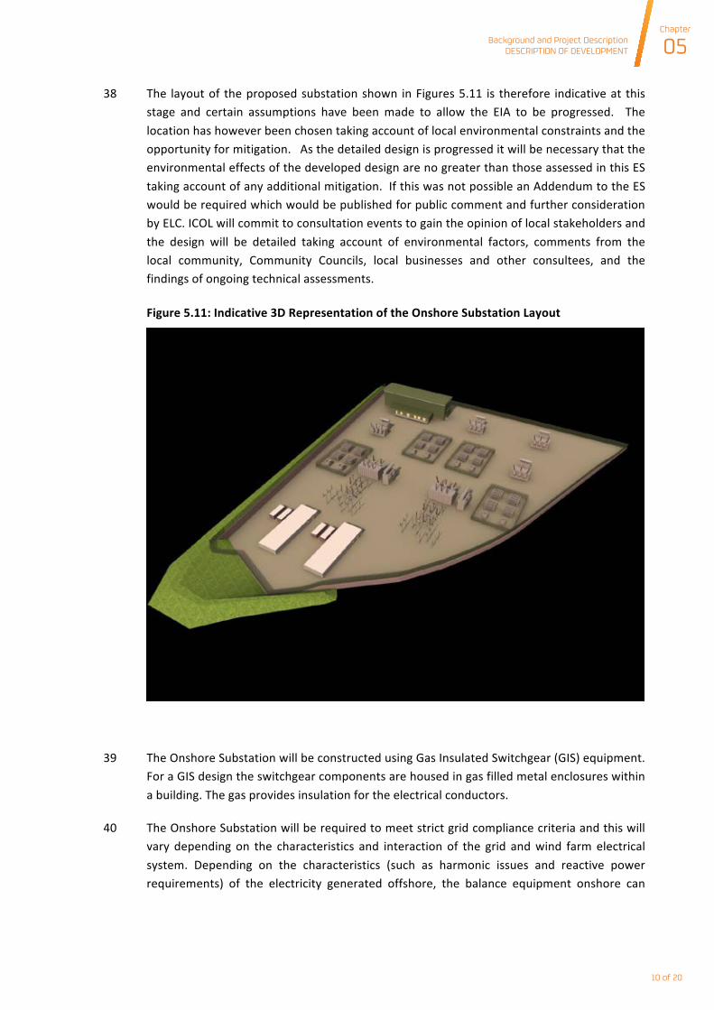
38 The layout of the proposed substation shown in Figures 5.11 is therefore indicative at this stage and certain assumptions have been made to allow the EIA to be progressed. The location has however been chosen taking account of local environmental constraints and the opportunity for mitigation. As the detailed design is progressed it will be necessary that the environmental effects of the developed design are no greater than those assessed in this ES taking account of any additional mitigation. If this was not possible an Addendum to the ES would be required which would be published for public comment and further consideration by ELC. ICOL will commit to consultation events to gain the opinion of local stakeholders and the design will be detailed taking account of environmental factors, comments from the local community, Community Councils, local businesses and other consultees, and the findings of ongoing technical assessments.
Figure 5.11: Indicative 3D Representation of the Onshore Substation Layout
39 The Onshore Substation will be constructed using Gas Insulated Switchgear (GIS) equipment. For a GIS design the switchgear components are housed in gas filled metal enclosures within a building. The gas provides insulation for the electrical conductors.
40 The Onshore Substation will be required to meet strict grid compliance criteria and this will vary depending on the characteristics and interaction of the grid and wind farm electrical system. Depending on the characteristics (such as harmonic issues and reactive power requirements) of the electricity generated offshore, the balance equipment onshore can
Background and Project DescriptionDESCRIPTION OF DEVELOPMENT
Chapter
05
INCH CAPE OFFSHORE LIMITED ONSHORE ENVIRONMENTAL STATEMENT
10 of 20
Background and Project Description DESCRIPTION OF DEVELOPMENT
INCH CAPE OFFSHORE LIMITED ONSHORE ENVIRONMENTAL STATEMENT
Chapter
05
11 of 20
change, which in turn can affect the total footprint, maximum height and total fenced area of the Onshore Substation.
41 It is anticipated that the Onshore Substation Site footprint will be approximately 2.7 ha and will consist of the following elements (note that all measurements provided are approximate only at this stage):
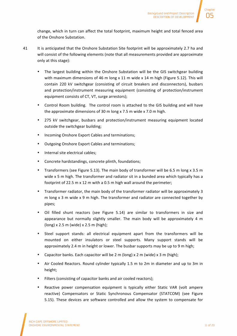
• The largest building within the Onshore Substation will be the GIS switchgear building with maximum dimensions of 46 m long x 11 m wide x 14 m high (Figure 5.12). This will contain 220 kV switchgear (consisting of circuit breakers and disconnectors), busbars and protection/instrument measuring equipment (consisting of protection/instrument equipment consists of CT, VT, surge arrestors);
• Control Room building. The control room is attached to the GIS building and will have the approximate dimensions of 30 m long x 7.5 m wide x 7.0 m high.
• 275 kV switchgear, busbars and protection/instrument measuring equipment located outside the switchgear building;
• Incoming Onshore Export Cables and terminations;
• Outgoing Onshore Export Cables and terminations;
• Internal site electrical cables;
• Concrete hardstandings, concrete plinth, foundations;
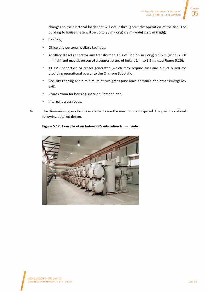
• Transformers (see Figure 5.13). The main body of transformer will be 6.5 m long x 3.5 m wide x 5 m high. The transformer and radiator sit in a bunded area which typically has a footprint of 22.5 m x 12 m with a 0.5 m high wall around the perimeter;
• Transformer radiator, the main body of the transformer radiator will be approximately 3 m long x 3 m wide x 9 m high. The transformer and radiator are connected together by pipes;
• Oil filled shunt reactors (see Figure 5.14) are similar to transformers in size and appearance but normally slightly smaller. The main body will be approximately 4 m (long) x 2.5 m (wide) x 2.5 m (high);
• Steel support stands: all electrical equipment apart from the transformers will be mounted on either insulators or steel supports. Many support stands will be approximately 2.4 m in height or lower. The busbar supports may be up to 9 m high;
• Capacitor banks. Each capacitor will be 2 m (long) x 2 m (wide) x 3 m (high);
• Air Cooled Reactors. Round cylinder typically 1.5 m to 2m in diameter and up to 3m in height;
• Filters (consisting of capacitor banks and air cooled reactors);
• Reactive power compensation equipment is typically either Static VAR (volt ampere reactive) Compensators or Static Synchronous Compensator (STATCOM) (see Figure 5.15). These devices are software controlled and allow the system to compensate for
Background and Project DescriptionDESCRIPTION OF DEVELOPMENT
Chapter
05
INCH CAPE OFFSHORE LIMITED ONSHORE ENVIRONMENTAL STATEMENT
11 of 20
Background and Project Description DESCRIPTION OF DEVELOPMENT
INCH CAPE OFFSHORE LIMITED ONSHORE ENVIRONMENTAL STATEMENT
Chapter
05
12 of 20
changes to the electrical loads that will occur throughout the operation of the site. The building to house these will be up to 30 m (long) x 3 m (wide) x 2.5 m (high);
• Car Park;
• Office and personal welfare facilities;
• Ancillary diesel generator and transformer. This will be 2.5 m (long) x 1.5 m (wide) x 2.0 m (high) and may sit on top of a support stand of height 1 m to 1.5 m. (see Figure 5.16);
• 11 kV Connection or diesel generator (which may require fuel and a fuel bund) for providing operational power to the Onshore Substation;
• Security Fencing and a minimum of two gates (one main entrance and other emergency exit);
• Spares room for housing spare equipment; and
• Internal access roads.
42 The dimensions given for these elements are the maximum anticipated. They will be defined following detailed design.
Figure 5.12: Example of an Indoor GIS substation from Inside
Background and Project DescriptionDESCRIPTION OF DEVELOPMENT
Chapter
05
INCH CAPE OFFSHORE LIMITED ONSHORE ENVIRONMENTAL STATEMENT
12 of 20
Background and Project Description DESCRIPTION OF DEVELOPMENT
INCH CAPE OFFSHORE LIMITED ONSHORE ENVIRONMENTAL STATEMENT
Chapter
05
13 of 20
Figure 5.13: Example of Auxiliary Transformer
Figure 5.14: Example of Shunt Reactor
Figure 5.15: Example of STATCOM
Background and Project DescriptionDESCRIPTION OF DEVELOPMENT
Chapter
05
INCH CAPE OFFSHORE LIMITED ONSHORE ENVIRONMENTAL STATEMENT
13 of 20

Background and Project Description DESCRIPTION OF DEVELOPMENT
INCH CAPE OFFSHORE LIMITED ONSHORE ENVIRONMENTAL STATEMENT
Chapter
05
14 of 20
Figure 5.16: Example of Transformer Area
Onshore Substation Description of Works
43 Further ground investigations will be undertaken to assess the ground conditions in more detail and identify what remedial action, if any, is required prior to the commencement of works.
44 Cable routes and internal access road works will be established, followed by the construction of the necessary switchgear/control building then installation of external components, internal components and finally cable installation. After testing and commissioning, reinstatement works will be carried out to the temporary work areas.
45 Once the initial Onshore Substation Site and external access track are established, initial ground works will be undertaken to prepare the location for the Onshore Substation. This will involve removing the top layer of earth and the reduction of ground level at the Onshore Substation by up to approximately three meters before levelling the land and installing an earthing conductor, drainage and foundations. Once the foundations are laid, internal access roadways will be constructed followed by the delivery and installation of the Onshore Substation components. Other enabling works may be required onsite such as relocation of services. A balanced cut and fill operation will be undertaken if possible.
46 All of the electrical infrastructure will be manufactured offsite and transported to site for subsequent assembly A security fence of up to three metre height will be erected around the perimeter of the Onshore Substation and warning signs posted. Twenty-‐four hour security will be in place for the duration of the construction period.
5.3.6 Onshore Export Cable Corridor between the Onshore Substation and the grid connection point
47 The Onshore Export Cables that run from the Onshore Substation to the grid connection point will be laid in up to two trenches in the same manner as that described in Section 5.3.3.
Background and Project DescriptionDESCRIPTION OF DEVELOPMENT
Chapter
05
INCH CAPE OFFSHORE LIMITED ONSHORE ENVIRONMENTAL STATEMENT
14 of 20

Background and Project Description DESCRIPTION OF DEVELOPMENT
INCH CAPE OFFSHORE LIMITED ONSHORE ENVIRONMENTAL STATEMENT
Chapter
05
15 of 20
48 It is anticipated that the Onshore Export Cable from the Onshore Substation to the grid connection point will be approximately 1 km long and may require jointing pits at appropriate locations to be determined (Section 5.3.4).
49 The Onshore Export Cable installation rate including trench digging, cable laying and backfilling the trench, is around 30 -‐ 45 m/day. It is expected that the installation between the Onshore Substation and the grid connection point will require approximately between 25 and 36 days per cable.
5.3.7 Construction Compound Description of Works
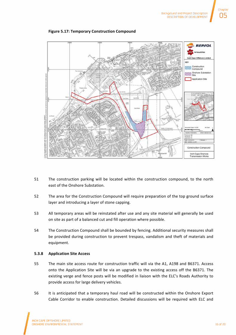
50 An area of approximately 1.7 hectares adjacent to the Onshore Substation will be used to accommodate the temporary work site (see Figure 5.17), known as the Construction Compound and will include:
• Construction parking (located to the north east of the Onshore Substation, close to the Application Site Access);
• Construction welfare facilities (kitchen/cafeteria/drying room);
• Construction meeting room;
• Construction laydown and storage area;
• Construction security facilities (CDM fenced area/gate and security access);
• Construction security lighting; and
• Construction security guards 24/7.
Background and Project DescriptionDESCRIPTION OF DEVELOPMENT
Chapter
05
INCH CAPE OFFSHORE LIMITED ONSHORE ENVIRONMENTAL STATEMENT
15 of 20
Background and Project Description DESCRIPTION OF DEVELOPMENT
INCH CAPE OFFSHORE LIMITED ONSHORE ENVIRONMENTAL STATEMENT
Chapter
05
16 of 20
Figure 5.17: Temporary Construction Compound
51 The construction parking will be located within the construction compound, to the north east of the Onshore Substation.
52 The area for the Construction Compound will require preparation of the top ground surface layer and introducing a layer of stone capping.
53 All temporary areas will be reinstated after use and any site material will generally be used on site as part of a balanced cut and fill operation where possible.
54 The Construction Compound shall be bounded by fencing. Additional security measures shall be provided during construction to prevent trespass, vandalism and theft of materials and equipment.
5.3.8 Application Site Access
55 The main site access route for construction traffic will via the A1, A198 and B6371. Access onto the Application Site will be via an upgrade to the existing access off the B6371. The existing verge and fence posts will be modified in liaison with the ELC’s Roads Authority to provide access for large delivery vehicles.
56 It is anticipated that a temporary haul road will be constructed within the Onshore Export Cable Corridor to enable construction. Detailed discussions will be required with ELC and
Background and Project DescriptionDESCRIPTION OF DEVELOPMENT
Chapter
05
INCH CAPE OFFSHORE LIMITED ONSHORE ENVIRONMENTAL STATEMENT
16 of 20

Background and Project Description DESCRIPTION OF DEVELOPMENT
INCH CAPE OFFSHORE LIMITED ONSHORE ENVIRONMENTAL STATEMENT
Chapter
05
17 of 20
other stakeholders as to the exact routing, land agreements, service diversions and traffic management proposals (passing places etc.). Further investigation during detailed design may offer the potential for an alternative to the temporary haul road to further reduce any potential effects.
57 Most Onshore Substation equipment will be delivered into the construction compound or directly to its installation location within the Onshore Substation. Typically assembly of equipment will occur in both the Onshore Substation and in the construction compound.
5.3.9 Enabling Works
58 To prepare the Application Site, remedial/enabling work will be required prior to any project works commencing. This will include the decommissioning and removal of the existing rail track which runs through the Onshore Substation Site and potentially re-‐routing or protecting existing utilities.
5.3.10 Construction Working Hours
59 The permitted working hours for noisy operations on the Application Site that are audible at the Application Site boundary will be restricted to between 0700 – 1900 Monday to Friday inclusive, and 0800 – 1300 on Saturdays unless otherwise agreed with ELC. It is assumed there will be no working on Sunday, unless with prior arrangement with ELC. However, twenty four hour working, seven days per week has been assumed at the Landfall if the horizontal directional drilling technique is employed to lay the cables due to tidal influence. Local residents with the potential to be disturbed by noise will be consulted with regards to work patterns and appropriate controls will be implemented.
5.3.11 Construction Environmental Management Plan and Community Liaison
60 Prior to the construction works a Construction Environmental Management Plan (CEMP) will be prepared by the Principal Contractor and submitted to ELC for their approval. This will be in addition to any more generic environmental management systems (EMS) such as ISO 140011 which the contractor works under. The CEMP will set out procedures to ensure all activities with potential to affect the environment are appropriately managed. The CEMP will incorporate any submissions such as method statements or work procedures relating to mitigation as agreed with ICOL and other statutory consultees as part of the planning consent conditions. All environmental risks and necessary protection measures (including mitigation measures set out in this ES) will be required to be identified and integrated in the contractor’s method statements for all major construction activities. The CEMP will be included as part of the overall site management and operational procedures. An outline of the contents of the CEMP is provided in Table 5.1.
1 ISO 14001 is an international standard for environmental management
Background and Project DescriptionDESCRIPTION OF DEVELOPMENT
Chapter
05
INCH CAPE OFFSHORE LIMITED ONSHORE ENVIRONMENTAL STATEMENT
17 of 20
Background and Project Description DESCRIPTION OF DEVELOPMENT
INCH CAPE OFFSHORE LIMITED ONSHORE ENVIRONMENTAL STATEMENT
Chapter
05
18 of 20
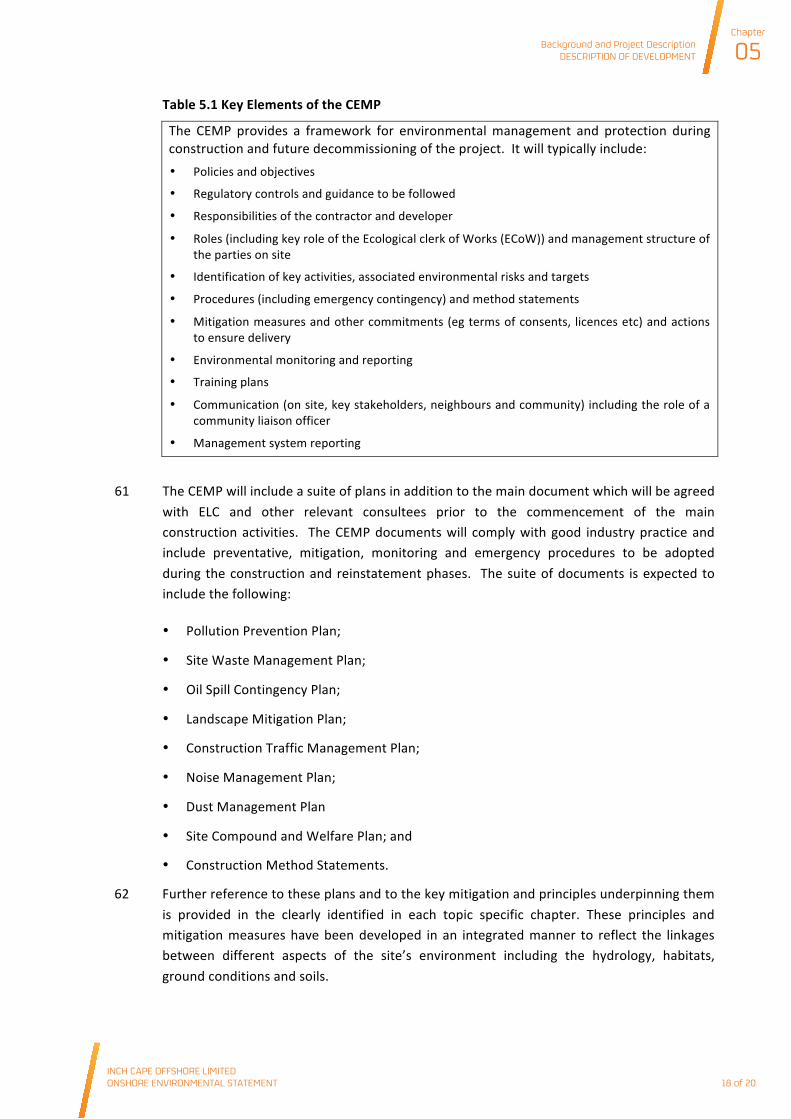
Table 5.1 Key Elements of the CEMP
The CEMP provides a framework for environmental management and protection during construction and future decommissioning of the project. It will typically include: • Policies and objectives
• Regulatory controls and guidance to be followed
• Responsibilities of the contractor and developer
• Roles (including key role of the Ecological clerk of Works (ECoW)) and management structure of the parties on site
• Identification of key activities, associated environmental risks and targets
• Procedures (including emergency contingency) and method statements
• Mitigation measures and other commitments (eg terms of consents, licences etc) and actions to ensure delivery
• Environmental monitoring and reporting
• Training plans
• Communication (on site, key stakeholders, neighbours and community) including the role of a community liaison officer
• Management system reporting
61 The CEMP will include a suite of plans in addition to the main document which will be agreed with ELC and other relevant consultees prior to the commencement of the main construction activities. The CEMP documents will comply with good industry practice and include preventative, mitigation, monitoring and emergency procedures to be adopted during the construction and reinstatement phases. The suite of documents is expected to include the following:
• Pollution Prevention Plan;
• Site Waste Management Plan;
• Oil Spill Contingency Plan;
• Landscape Mitigation Plan;
• Construction Traffic Management Plan;
• Noise Management Plan;
• Dust Management Plan
• Site Compound and Welfare Plan; and
• Construction Method Statements.
62 Further reference to these plans and to the key mitigation and principles underpinning them is provided in the clearly identified in each topic specific chapter. These principles and mitigation measures have been developed in an integrated manner to reflect the linkages between different aspects of the site’s environment including the hydrology, habitats, ground conditions and soils.
Background and Project DescriptionDESCRIPTION OF DEVELOPMENT
Chapter
05
INCH CAPE OFFSHORE LIMITED ONSHORE ENVIRONMENTAL STATEMENT
18 of 20
Background and Project Description DESCRIPTION OF DEVELOPMENT
INCH CAPE OFFSHORE LIMITED ONSHORE ENVIRONMENTAL STATEMENT
Chapter
05
19 of 20
63 All site staff will receive appropriate environmental training at the beginning of the contract and throughout the construction period as required. The contractor’s compliance with environmental procedures including measures for pollution prevention and monitoring of performance will be implemented by the contractor and monitored independently by ICOL and their environmental team.
64 The contractor will be required to establish and maintain effective liaison with the local community throughout construction. This will include information about the ongoing activities and provision of contact telephone numbers to contact the site for information during working hours. A person will be identified with appropriate authority to resolve any problems. A log of complaints and actions taken to remedy these will be available for inspection.
65 The contractor will be required to ensure disturbance to local community from construction activities was minimised to that required for safe implementation of the works.
66 A community liaison officer will be appointed prior to and for the duration of the works as part of the Noise Management Plan and to promote communication with the local community and businesses.
5.3.12 Construction Programme
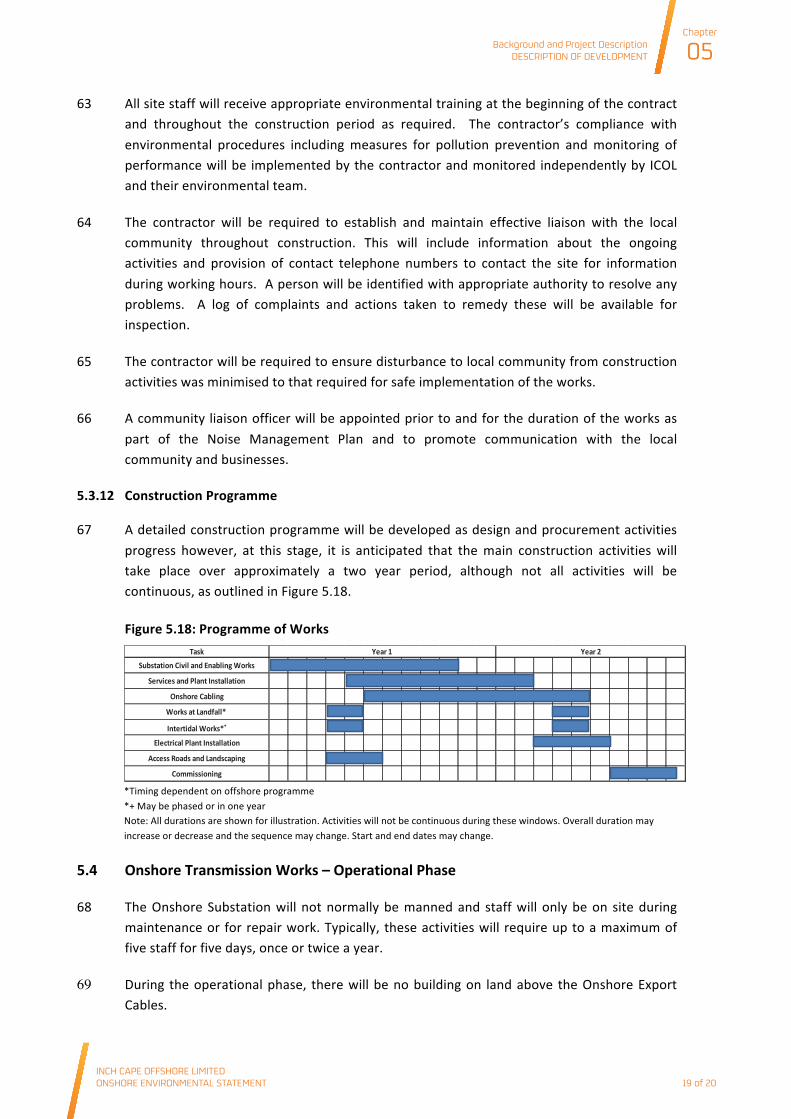
67 A detailed construction programme will be developed as design and procurement activities progress however, at this stage, it is anticipated that the main construction activities will take place over approximately a two year period, although not all activities will be continuous, as outlined in Figure 5.18.
Figure 5.18: Programme of Works
*Timing dependent on offshore programme *+ May be phased or in one year Note: All durations are shown for illustration. Activities will not be continuous during these windows. Overall duration may increase or decrease and the sequence may change. Start and end dates may change.
5.4 Onshore Transmission Works – Operational Phase
68 The Onshore Substation will not normally be manned and staff will only be on site during maintenance or for repair work. Typically, these activities will require up to a maximum of five staff for five days, once or twice a year.
69 During the operational phase, there will be no building on land above the Onshore Export Cables.
Task
Substation Civil and Enabling Works
Services and Plant Installation
Onshore Cabling
Works at Landfall*
Intertidal Works*+
Electrical Plant Installation
Access Roads and Landscaping
Commissioning
Year 1 Year 2
Background and Project DescriptionDESCRIPTION OF DEVELOPMENT
Chapter
05
INCH CAPE OFFSHORE LIMITED ONSHORE ENVIRONMENTAL STATEMENT
19 of 20

Background and Project Description DESCRIPTION OF DEVELOPMENT
INCH CAPE OFFSHORE LIMITED ONSHORE ENVIRONMENTAL STATEMENT
Chapter
05
20 of 20
70 There may be occasions for day visits to the Onshore Substation by one or two staff.
71 No maintenance will be required on the Onshore Export Cables other than an inspection of the link boxes. This will take approximately one day every year.
72 If a cable fault occurs during the operation of the OnTW cable repair work will be undertaken. During the cable repair work the jointing of the cable will usually require a temporary working facility to be established. This would typically be a container similar in size to a shipping container eg 6 m (long) x 2.5 m (wide) x 2.5 m (high). The container would be located within the proximity of the fault for approximately seven days. Approximately five staff would be required to excavate and cover the cable, and three staff to repair the fault. The container would be sited sensitively in consultation with ELC and to avoid environmental constraints where possible.
73 Security during operations will typically be supplied by a contractor supplying services such as site attendance within 15 minutes of security alarm and weekly walk round site and cable route. CCTV may be installed for the operational stage of the Onshore Substation.
5.5 Onshore Transmission Works – Decommissioning Phase
74 The OnTW will be decommissioned following the end of their operational life which is not fixed but anticipated to be up to 50 years. A draft decommissioning plan will be prepared prior to construction and a final plan prior to decommissioning. This final plan will take into account any other projects and activities that are taking place at the time in the Study Area.
Background and Project DescriptionDESCRIPTION OF DEVELOPMENT
Chapter
05
INCH CAPE OFFSHORE LIMITED ONSHORE ENVIRONMENTAL STATEMENT
20 of 20


![INDEX [] · 2.0 Introduction of the Project / Background Information 3 (i) Identification of Project & Project Proponent 3 (ii) Brief Description of Nature of the Project 6 (iii)](https://static.fdocuments.net/doc/165x107/60ca7fe365382b0711542d7a/index-20-introduction-of-the-project-background-information-3-i-identification.jpg)


