Backfill Grouting - 株式会社タック1.Purpose of Backfill Grouting •It prevents collapse of...
20
Backfill Grouting 1 Liquid type(From Europe) And 2 Liquid type(From Japan)
Transcript of Backfill Grouting - 株式会社タック1.Purpose of Backfill Grouting •It prevents collapse of...

Backfill Grouting
1 Liquid type(From Europe)And
2 Liquid type(From Japan)

1.Purpose of Backfill Grouting
• It prevents collapse of Tail-void, then stabilizes looseness of soil-condition, keeps settlement.
• It stabilizes Segment-structure as soon as possible.
• It makes tunnel-track stable.• It protects gap of segment from water.

2.Injection ways of grouting• Injection way is due to injection timing and layout of
injection hole.• Simultaneous injection is the most effective.
Injection behind Excavation
Segment holes(With manual system)
ImmediateInjection
Simultaneous Injection withExcavation
TBM’s Pipes(With automatic system)
SimultaneousInjection
TimingLayout of injection hole
Simultaneous Injection(From TBM’s pipe)
Immediate Injection(From segment hole)
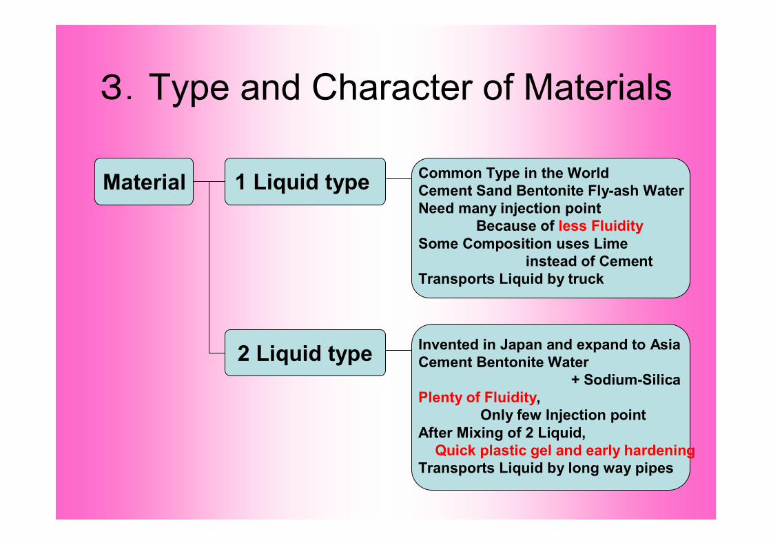
3.Type and Character of Materials
Material 1 Liquid type
2 Liquid type
Common Type in the WorldCement Sand Bentonite Fly-ash WaterNeed many injection point
Because of less FluiditySome Composition uses Lime
instead of CementTransports Liquid by truck
Invented in Japan and expand to AsiaCement Bentonite Water
+ Sodium-SilicaPlenty of Fluidity,
Only few Injection pointAfter Mixing of 2 Liquid,
Quick plastic gel and early hardeningTransports Liquid by long way pipes

1 Liquid type
StickyHigh densityLess FluidityLong time hardening

2 Liquid type
AB
A+B
Mixing GelB Liquid Jet
liquid area gel time plastic area hard area
1 day 30 minuts10 seconds↑
Strongth
B liquid
A liquid
Time→

4.Design ways of Equipment 1
Exca
vate
diam
eter
D’
TBM
Diam
eter
D
Segm
entdi
amet
erd
A Unit of Tail-void Volume=π/4(D2-d2)
<General> Injection Volume L(1m unit)= Tail-void Volume×RateRate is usually 130% due to looseness of soils
<Considering soils> Sometimes Rate depend on soil types
140~160130~150130~150130Rate(%)
Stone GravelSand GravelLoose ClayHard Clay
1.TBM and Tail-void
2. Calculation A Unit of Tail-void Volume

Design ways of Equipment 23.Jack-Speed and Injection-flow volume
For 2 liquid type, each volume needs to calculate
Injection-flow volume (L/min)=(Injection volume(L)×JS(mm/min))/100
4.Choice of Pumps
• Pump’s Choice is due to 1Liquid type and 2. • For 1 Liquid type, Piston type (High Pressure type)• For 2 Liquid type, any kind of pumps is OK.
2 pumps are needed (For 2 Liquid, large and small )• Decide quantity of Pump by points and volume.• For 1 Liquid type, many pumps are needed because
Material is not easy to encircle Segment completly.• For 2 Liquid type, easy to encircle, proper volume is
100~150L/min by one place.
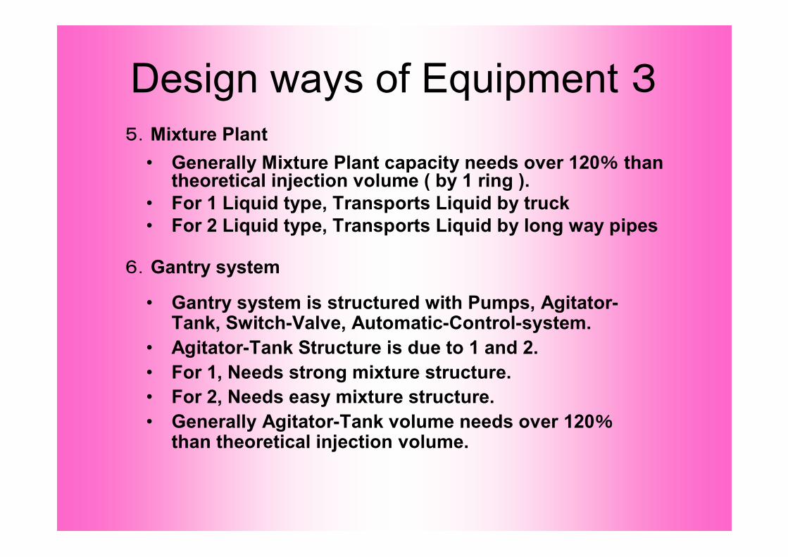
Design ways of Equipment 35.Mixture Plant
• Generally Mixture Plant capacity needs over 120% than theoretical injection volume ( by 1 ring ).
• For 1 Liquid type, Transports Liquid by truck • For 2 Liquid type, Transports Liquid by long way pipes
6.Gantry system
• Gantry system is structured with Pumps, Agitator-Tank, Switch-Valve, Automatic-Control-system.
• Agitator-Tank Structure is due to 1 and 2.• For 1, Needs strong mixture structure.• For 2, Needs easy mixture structure.• Generally Agitator-Tank volume needs over 120%
than theoretical injection volume.
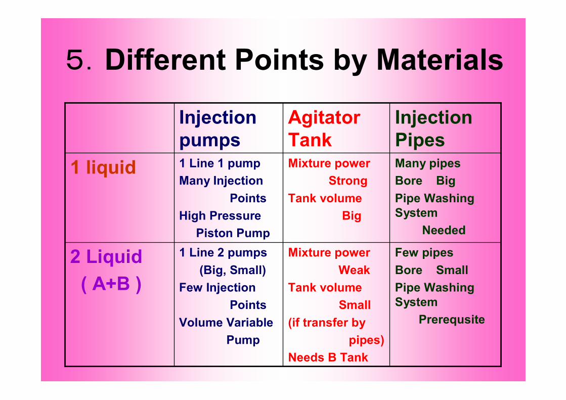
5.Different Points by Materials
Few pipesBore SmallPipe Washing System
Prerequsite
Mixture powerWeak
Tank volume Small
(if transfer bypipes)
Needs B Tank
1 Line 2 pumps(Big, Small)
Few InjectionPoints
Volume VariablePump
2 Liquid( A+B )
Many pipesBore BigPipe Washing System
Needed
Mixture powerStrong
Tank volume Big
1 Line 1 pumpMany Injection
PointsHigh Pressure
Piston Pump
1 liquid
Injection Pipes
Agitator Tank
Injection pumps
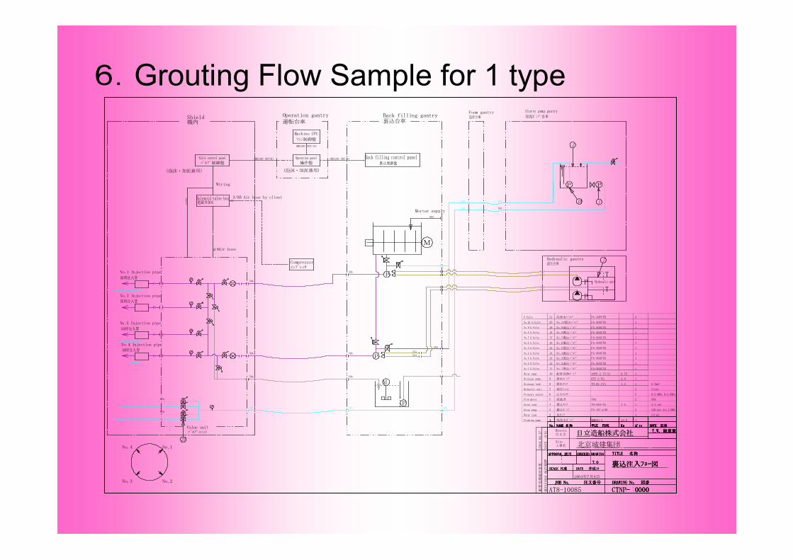
6.Grouting Flow Sample for 1 type
DATE
日付
0000
裏込注入フロー図
APPROVAL 認可 CHECKED
注文番号JOB No. 図番DRAWING No.
DRAWING
-
T.W. 総重量
TITLE 名称
REVISIONS
改訂
履歴
SCALE 尺度 DATE 作成日
APPROVAL 認可 CHECKED
JOB No.
DRAWING
Messrs.注文主
Site工事名
T.W. 総重量
TITLE 名称
SCALE 尺度裏込注入フロー図T.O
APPROVAL 認可 CHECKED
注文番号JOB No. 図番DRAWING No.
DRAWING
-
T.W. 総重量
TITLE 名称
SCALE 尺度 DATE 作成日
NOTE 記事NAME 名称No. Q'tyKw型式 TYPE NOTE 記事NAME 名称No. Q'tyKw型式 TYPE NOTE 記事NAME 名称No. Q'tyKw型式 TYPE NOTE 記事NAME 名称No. Q'tyKw型式 TYPE
0000
裏込注入フロー図T.O
APPROVAL 認可 CHECKED
注文番号JOB No. 図番DRAWING No.
DRAWING
-
T.W. 総重量
TITLE 名称
NOTE 記事NAME 名称No.
SCALE 尺度 DATE 作成日
Q'tyKw型式 TYPE
CTNP
日立造船株式会社
50A
3.5 m3
120L/min Ave.2.0MPa
2.0m3
1
1
5
1
1
1
1
2
2
1
1
1
2
7.5
15.0
0.75
1.5
2.0
PA-15Cφ90
TO-350-75
40PN 2.75-51
TO-02-275
KTV-2-50
2
3
4
5
6
7
8
9
10
11
12
13
14
15
16
17
18
1.Flushing pump
Water tank
Grout pump
Grout tank
Flow meter
Pressure sensor
19
20
1.
Hydraulic unit
Drainage tank
Drainage pump
Water pump
洗浄水ポンプ
流量計
圧力センサー
裏込ポンプ
裏込タンク
水タンク
油圧ユニット
排水タンク
排水ポンプ
配管洗浄ポンプ
21
1
1
1
1
1
1
1
No.1 G.Valve
No.2 G.Valve
No.3 G.Valve
No.4 G.Valve
No.5 G.Valve
No.6 G.Valve
No.7 G.Valve
No.8 G.Valve
No.9 G.Valve
No.10 G.Valve
F.Valve 4
50A
MMK50/4
2004年7月8日
0000
北京城建集団
裏込注入フロー図T.O
APPROVAL 認可 CHECKED
注文番号JOB No. 図番DRAWING No.
DRAWING
-
T.W. 総重量
TITLE 名称
NOTE 記事NAME 名称No.
SCALE 尺度 DATE 作成日
CTNP
Q'tyKw型式 TYPE
日立造船株式会社
AT8-10085配管
受渡場
所変
更2004.08.17
FA-300UTB
FA-300UTB
FA-300UTB
FA-300UTB
FA-300UTB
FA-300UTB
FA-300UTB
FA-300UTB
FA-300UTB
FA-300UTB
FA-10FCTB
Client
2.0 m3
No.10裏込バルブ
No.9裏込バルブ
洗浄水バルブ
No.8裏込バルブ
No.7裏込バルブ
No.6裏込バルブ
No.5裏込バルブ
No.4裏込バルブ
No.3裏込バルブ
No.2裏込バルブ
No.1裏込バルブ
0-3.0MPa 0-2.0MPa
Mortar supply
3/8B Air hose by client
Foam gantry
A
No.4 Injection pipe
No.3 Injection pipe
No.2 Injection pipe
No.1 Injection pipe
No.4
No.3 No.2
No.1
50A
同時注入管
同時注入管
同時注入管
同時注入管
50A
P
M
21
Slurry pump gantry
加泥ポンプ台車
AA
10
7
1
P
A
A
A
A
50A
40A
40A
AA
A
A
A
A
A
A
50A
泡沫台車
TP
Hydraulic unit
油圧台車
2
Hydraulic gantry
P
PT
Solenoid valve box
(泡沫・加泥兼用) (泡沫・加泥兼用)
25A25A
50A
P50A50A
φ8Air hose
Wiring
Back filling gantryShield
Back filling control panel裏込制御盤
80A
P
M
裏込台車
(MELSEC NET/B)
Valne unitバルブユニット
運転台車
電磁弁BOXcable
Valve control panelバルブ制御盤
Operation panel操作盤
(MELSEC NET/B)
(MELSEC NET/10)
Compressorコンプレッサ
機内
Machine CPU
マシン制御盤
Operation gantry
50A
50A 50A
50A
50A 50A50A
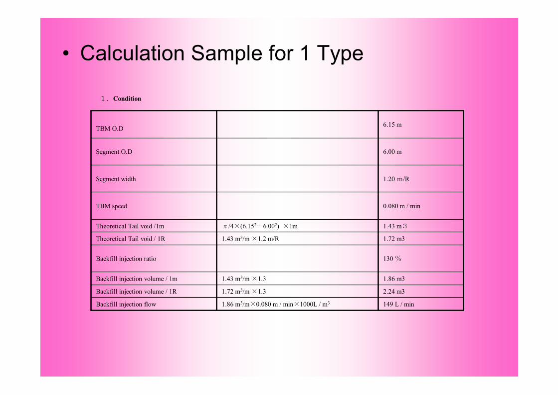
1.Condition
149 L / min1.86 m3/m×0.080 m / min×1000L / m3Backfill injection flow
2.24 m31.72 m3/m ×1.3Backfill injection volume / 1R
1.86 m31.43 m3/m ×1.3Backfill injection volume / 1m
130 %Backfill injection ratio
1.72 m31.43 m3/m ×1.2 m/R Theoretical Tail void / 1R
1.43 m3π/4×(6.152-6.002) ×1mTheoretical Tail void /1m
0.080 m / minTBM speed
1.20 m/RSegment width
6.00 mSegment O.D
6.15 mTBM O.D
• Calculation Sample for 1 Type

2.Specifications
Share it with foaming systemSolenoid valve box
Share it with foaming systemValve control panel
Tank control panel
Backfill system control panel
Auto/hand operationTouch sensor panelOperation panel
4 Pneumatic valves system manifoldCleaning valve unit
12 Pneumatic valves system manifoldValve unit
5setPressure sensor
Magnetic flow meter2setFlow meter
2.0kwDrainage pump
2.0M3 1.5KwDrainage tank
2.0M3Water tank
5.5kw 130mFlushing pump
By the client 22kw ×2 Hydraulic unit
> 149 L/minPiston pump1.0~2.0Mpa (normally using) Maximum 5.0MPa (especially using)Flow Maximum 120L/min(at no-load running)×2
Grout pump
> 2.24 m3 / R3.5 m3 7.5kw (actually3.0m3)Tank
• Specification Sample for 1 Type
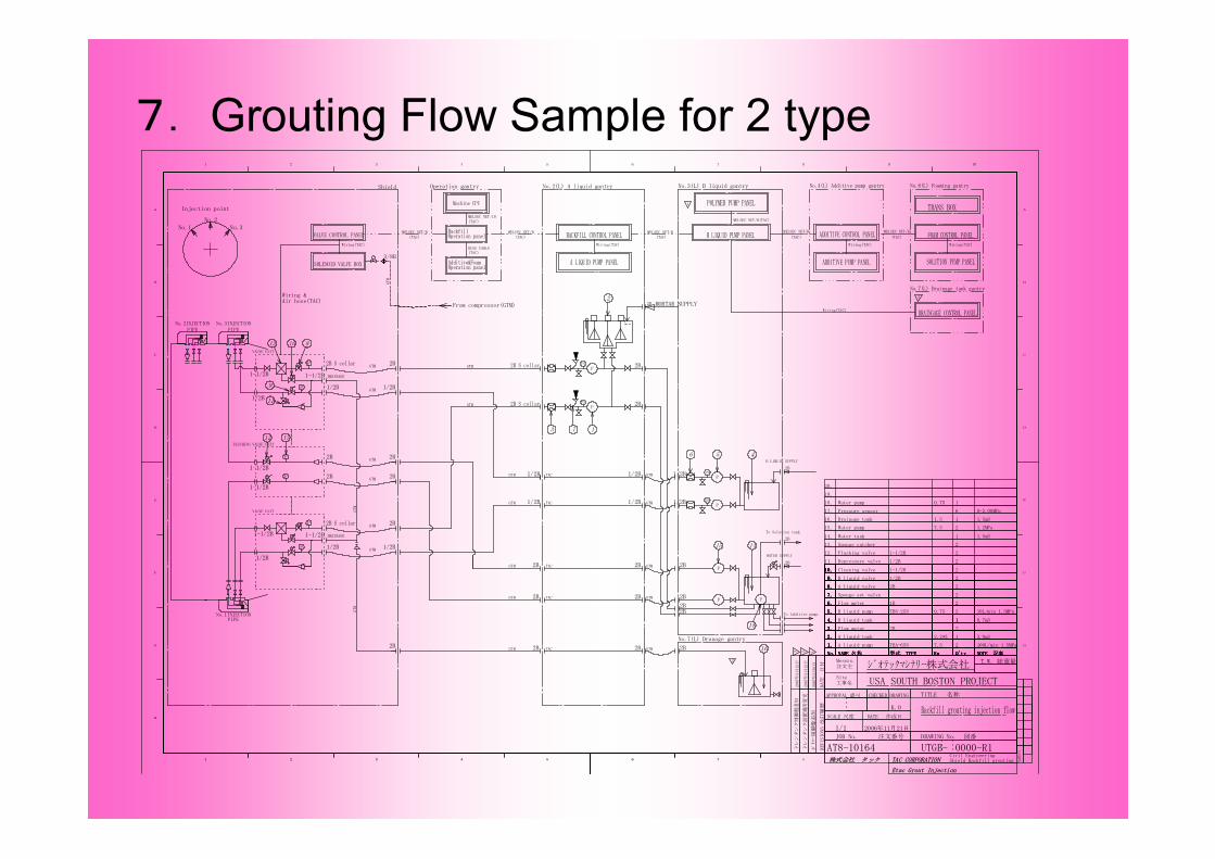
7. Grouting Flow Sample for 2 type
1.
2.
3.
4.
5.
6.
7.
8.
9.
10.
11.
12.
13.
14.
15.
16.
17.
18.
19.
1.
No.
20.
2.
3.
4.
5.
6.
7.
8.
9.
10.
1.
NOTE 記事NAME 名称No. Q'tyKw型式 TYPE
1 2 3 4 5 6 7
A liquid tank
Flow meter
11B liquid tank
A liquid pump
Water tank 1
Water pump 1.2MPa
Flow meter
Cleaning valve
Depressure valve
Sponge set valve
Sponge catcher
Flushing valve
B liquid pump
2B
2
1
TBN-25N 0.75 2 10L/min 1.5MPa
7.5
3.0m31
2
2
2
2
2
2
2
2
2
2B
1/2B
P
A
A
P
A
A9
11
PIPE PIPENo.2INJECTION
2B
1/2B
P
A
A
P
A
A
PIPE
2BA 2B
12
2BA P
P
100L/min 1.5MPa2
8
7.5
1.5m31.5
1.5m3
13
TBA-65N
2B
Pressure sensor 6 0-2.00MPa
17
2.2*3
Machine CPU
MELSEC NET/10(TAC)
Operation panelAdditive&Foam
Operation panelBackfill
Operation gantry
PS
PS
PS
PS
P
P
P
P
P
P
3 7 1
5
15
1/2B
1/2B
2B MORTAR SUPPLY
2B
2BA
MELSEC NET/B(TAC)
MELSEC NET/B(TAC)
MELSEC NET/B(TAC) (TAC)
MELSEC NET/B
GTM
GTM
GTM
GTM
GTM
(TAC)BUSS CABLE
From compressor(GTM)
GTM
GTM
GTM
2.
3.
4.
5.
6.
7.
8.
9.
10.
1.
No. NOTE 記事NAME 名称 Q'tyKw型式 TYPE
2.
3.
4.
5.
6.
7.
8.
9.
10.
1.
No. NOTE 記事NAME 名称 Q'tyKw型式 TYPE
14
P
4
Wiring(TAC)
Wiring &Air hose(TAC)
TAC
TAC
TAC
TAC
TAC
Water pump 10.75
ADDITIVE CONTROL PANEL
Injection point
No.2
No.2(L) A liquid gantry No.3(L) B liquid gantry
B LIQUID PUMP PANEL
ADDITIVE PUMP PANELA LIQUID PUMP PANEL
BACKFILL CONTROL PANEL
No.4(L) Additive pump gantry
(TAC)
MELSEC NET/BFOAM CONTROL PANEL
Wiring(TAC) Wiring(TAC)
3/8B
VALVE UNIT
VALVE UNIT
Wiring(TAC)
GTM
GTM
Drainage tank
No.3No.1
Shield
2
GTM
GTM
GTM
GTM
GTM
No.1INJECTION
No.3INJECTION
2B
2B
2B
2B2B
2B
2B
2B
2B
2B
2B
1/2B
1/2B
2B
2B
10
18
WATER SUPPLY
To Solution tank
B LIQUID SUPPLY
B liquid valve
A liquid valve
MELSEC NET/B(TAC)
16
No.7(L) Dranage gantry
ポリマー制御盤追加
2.
3.
4.
5.
6.
7.
8.
9.
10.
1.
1 2 3 4 5 6 7 8
G
TAC CORPORATIONCivil EngineeringShield Backfill grouting株式会社 タック
出図先
Etac Grout Injection
10987654321
A
B
C
D
E
F
H
A
B
C
D
E
F
G
No. NOTE 記事NAME 名称 Q'tyKw型式 TYPE
1/1 2006年11月21日
DATE
日付
0000-R1
USA SOUTH BOSTON PROJECT
K.O
APPROVAL 認可 CHECKED
注文番号JOB No. 図番DRAWING No.
DRAWING
-
Messrs.注文主
Site工事名
T.W. 総重量
TITLE 名称
REVISIONS改訂履
歴
SCALE 尺度 DATE 作成日
UTGB
ジオテックマシナリー株式会社
AT8-10164
Backfill grouting injection flow
2007年3月
8日
2007年3月
12日
ドレ
ンタン
ク設
置場所
変更
2 1
No.7(L) Drainage tank gantry
DRAINGAGE CONTROL PANELWiring(TAC)
2007年3月
12日
ドレ
ンタン
ク制
御盤追
加3
SOLUTION PUMP PANEL
No.6(L) Foaming gantry
To Additive pump
6
1/2B
1/2B
2B1-1/2B
1/2B
1/2B
1-1/2B
1-1/2B
1-1/2B
1-1/2B
1/2B
1-1/2B
1/2B
2B S collar
2B S collar
DRAINAGE
DRAINAGE
FLUSHING VALVE UNIT
GTM
GTM
GTM
GTM
GTM
GTM
POLYMER PUMP PANEL
VALVE CONTROL PANEL
SOLENOID VALVE BOX
2B S collar
2B S collar
2
1
3
TRANS BOX
0.7m3
2B
1B
2B
1/2B
1-1/2B
1/2B
1-1/2B

TBM O.D 5.86 m Segment O.D 5.69 m Segment width 1.219 m/R TBM speed 0.080 m / min Backfill injection ratio 135 % 2 liquid combination A : B =0.909: 0.091 10 : 1 Theoretical Tail void / 1m π/4×(5.862-5.662) ×1m 1.80 m3 Theoretical Tail void / 1R 1.80 m3/m ×1.219 m/R 2.19 m3 / R Backfill injection volume / 1m 1.80 m3/m ×1.35 2.43m3 Backfill injection volume / 1R 2.43 m3/m ×1.219 2.96 m3 Backfill injection flow 2.43 m3/m×0.080 m / min×1000L / m3 194 L / min Injection volume /1m of A liquid 2.43 m3/1m×0.909 2.21m3 Injection volume /1m of B liquid 2.43 m3/1m×0.091 0.22m3 Injection volume /1R of A liquid 2.96 m3/1R×0.909 2.69m3 Injection volume /1R of B liquid 2.96 m3/1R×0.091 0.27m3 A Liquid flow 2.21 m3/m×0.080 m / min 177 L / min B Liquid flow 0.22 m3/m×0.080 m / min 17.6L / min
• Calculation Sample for 2 Type
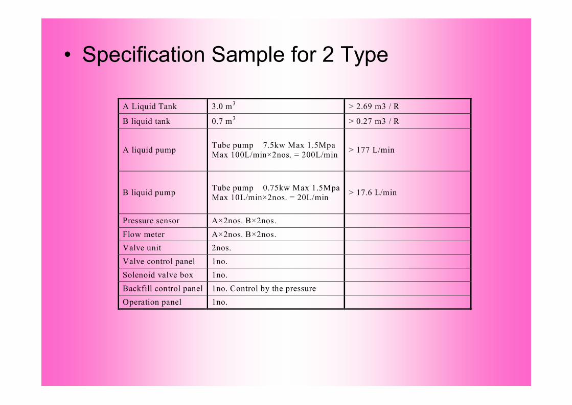
A Liquid Tank 3.0 m3 > 2.69 m3 / R
B liquid tank 0.7 m3 > 0.27 m3 / R
A liquid pump Tube pump 7.5kw Max 1.5Mpa Max 100L/min×2nos. = 200L/min > 177 L/min
B liquid pump Tube pump 0.75kw Max 1.5Mpa Max 10L/min×2nos. = 20L/min > 17.6 L/min
Pressure sensor A×2nos. B×2nos. Flow meter A×2nos. B×2nos. Valve unit 2nos. Valve control panel 1no. Solenoid valve box 1no. Backfill control panel 1no. Control by the pressure Operation panel 1no.
• Specification Sample for 2 Type

8.Variety of PumpsPiston Pump(PA型) Hydraulic
For 1 Liquid type
Tube Pump(TBA型)For 2 Liquid type
Snake PumpFor 2 Liquid type
Piston Pump(BG型)For 2 Liquid type

Variety of Pumps ・2
Piston Pump High Pressure (Putzmeister社 Schwing社)
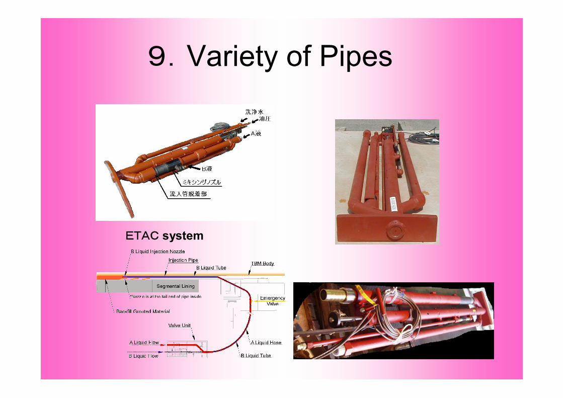
9.Variety of Pipes
ETAC system

10.Variety of Agitator-TankFor 2 Liquid type
Vertical TypeFor 1 Liquid typeHorizontal Type