
Back to Index Technical data BT - Birla Precision … Data.pdfTechnical data BT Form B coolant ......
10
Technical data BT Form B coolant Some toolholders are equipped with the form B coolant-style feature. CAUTION! Toolholders are factory set to the form B coolant supply position. When relocating coolant position screws, use of a removable liquid (small screw thread locker) is recommended. Possible variation of coolant supply to DIN 69871 form AD; tightening screws will stop coolant from escaping through the flange. 126 BT Shank MAS 403, JIS B6339 Back to Index
Transcript of Back to Index Technical data BT - Birla Precision … Data.pdfTechnical data BT Form B coolant ......

Technical data BT
Form B coolant
Some toolholders are equipped with the form B coolant-style feature.
CAUTION!
Toolholders are factory set to the form Bcoolant supply position. When relocatingcoolant position screws, use of aremovable liquid (small screw threadlocker) is recommended.
Possible variation of coolant supply toDIN 69871 form AD; tightening screwswill stop coolant from escapingthrough the flange.
126
BT Shank MAS 403, JIS B6339
Back to Index

DV– Shank DIN 69871/1 - ISO7388 FORM A/AD & FORM B/AD
Technical data DV
Form B coolant
Some toolholders are equipped with the form B coolant-style feature.
127
CAUTION!
Toolholders are factory set to the form Bcoolant supply position. When relocatingcoolant position screws, use of aremovable liquid (small screw threadlocker) is recommended.
Possible variation of coolant supply toDIN 69871 form AD; tightening screwswill stop coolant from escapingthrough the flange.
Back to Index

Technical data CV
Form B coolant
Some toolholders are equipped with the form B coolant-style feature.
128
CV– Shank ANSI-B5.50- FORM A/AD & FORM B/AD
CAUTION!
Toolholders are factory set to the form Bcoolant supply position. When relocatingcoolant position screws, use of aremovable liquid (small screw threadlocker) is recommended.
Possible variation of coolant supply toDIN 69871 form AD; tightening screwswill stop coolant from escapingthrough the flange.
Back to Index

Technical data HSK
ALSO AVAILABLE IN FORM B/ FORM C/ FORM D/ FORM E & FORM F SHANKS ON REQUEST
129
HSK Shank
Back to Index

Shank Dimension to DIN 6535 / Form HA and HE
General Application Instructions
130
Back to Index

Shank Dimension to DIN 6535 / Form HA and HE
General Application Instructions
131
Back to Index

Hydraulic Chuck
BPTL Hydraulic Chucks for ‘Precision Machining.’
• TIR within 3 microns at nose & 5 microns at 4 times the cutting tool diameters.
• Improved vibration damping by using patented silicon compound as the pressuring medium.
• Upto 800Nm transmittable torque, depending on the diameter.
• Improved surface finish of the work piece.
• Higher work piece accuracy.
• Upto 50% longer tool life.
• Increased productivity.
• Patented, leak-proof clamping system.
• Repeatability of 3 microns TIR over 50,000 cycles.
• Available on all popular taper shanks, including HSK
Slim line high-precision chuckBPTL Hydraulic Quality Chucks for ‘High-speed Machining.’• Slim line design and shorter reference dimensions; HSK tapers are also to standardized dimensions.
• Defined piston stroke-against stop-guarantees specified clamping forces.
• Two symmetrical pistons bore for the best repeatability and TIR. One screw for actuation.
• Cutting performance is far less susceptible to heat than with oil-filled high-precision chucks.
• Up to and including 20mm diameter, tools with Weldon or whistle-notch shank can be clampedwithout an intermediate sleeve, ensuring precision and run out accuracy.
• Excellent vibration damping due to silicon pressurizing medium, tool chatter and vibration arereduced, tool life and accuracy are increased.
• The integral clamping sleeve is hardened and tempered to reduce chuck wear and give a longerservice life.
• Extremely high clamping forces, 250Nm at 20mm diameter.
• Upto a speed of 15,000rpm, BPTL high precision chucks can be used without dynamic balancing.At speed above 15,000 and up to 25,000 rpm, additional dynamic balancing may be necessary.
• All BPTL hydraulic high-precision chucks are individually tested for accuracy and torque transmission.Each chuck receives its own certificate showing transmittable torque etc. to acceptable the followingminimum values must be achieved:( The values shown apply to slinline and Standard Chucks.)
Clamping Min.transferable
dia. (mm) torque moment (Nm)
6 12
8 20
10 40
12 70
14 100
16 150
18 210
20 250
25 420
32 800
132
Back to Index
Embedded EPS
There is embedded EPS on this page. Adobe Acrobat does not support the display of this type of object but it will print intact to a PostScript device.

Hydraulic Chuck
Instructions for Use – Hydraulic Tool holders.
Thoroughly CLEAN the tool SHANK and the tool holder BORE. Oil reduces the “Clamping force” by 1/3.
1. Insert the tool to the bottom of the tool holder. Please note tool shank must hold to the“h6” tolerance.
2. Tighten the pressure screw until fully engaged.
3. All tool holders are inspected 100% then individually certified stating actual run out, thusguaranteeing that run out will be no greater than 3 microns at the nose and 5 microns at 4 timesdiameter. Tool holders can be selected for improved run out specifications to the above. All toolholders are individually torque tested prior to leaving the factory to the minimum values statedbelow. The listed values are for round shafts all diameters. Weldon and whistle notch shanks up to20mm dia, all with “h6” shank tolerances held directly in the tool holder.
4. The actuating screw must not be tightened without tool inserted in the chuck.
133
Back to Index
Embedded EPS
There is embedded EPS on this page. Adobe Acrobat does not support the display of this type of object but it will print intact to a PostScript device.

Technical data shrink fit
Shrink Fit Technical details
SSSSShrhrhrhrhrink Fink Fink Fink Fink Fit it it it it TTTTTooooool Hol Hol Hol Hol Holder older older older older TTTTTechnicechnicechnicechnicechnical Infal Infal Infal Infal Infororororormamamamamation.tion.tion.tion.tion.
In shrink fit tool holder the internal bore size is slightly manufactured smaller than thecutting tool shank. By application of heat through the heating unit at holding nose areawill cause the inside bore to expand & the cutting tool shank can be inserted at thisstage. The holding nose is then cooled which shrinks the bore & firmly grips uniformlythe shank of the tool holder.
SSSSShrhrhrhrhrink Fink Fink Fink Fink Fit it it it it TTTTTooooool Hol Hol Hol Hol Holder Aolder Aolder Aolder Aolder Adddddvvvvvananananantagestagestagestagestages
• Greater Clamping Force over Collet Chucks / Hydraulic Chucks.
• Greatly recommended for high-speed application, due to symmetricity as noadditional parts are fitted. Improves surface finish & tool life.
• Guaranteed concentricity of 3 microns at nose due to uniform clamping force.
• Narrow nose design is suited for deep cavity.
• Supplied as pre balanced at G 6.3 @ 15,000 RPM
• Recommended to use “h6” tolerance cutting tool shank without flat.
134
Back to Index
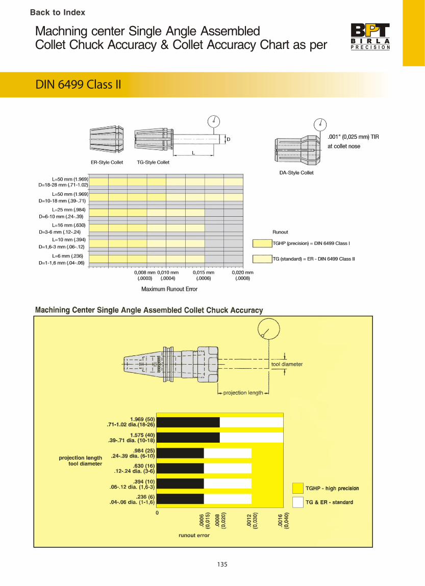
Machning center Single Angle AssembledCollet Chuck Accuracy & Collet Accuracy Chart as per
DIN 6499 Class II
135
Back to Index