BA PNOZ s7 2 en - sensotek.rusensotek.ru/upload/iblock/da0/da08d33c3926ec27130303f21478397b.pdf ·...
13
PNOZ s7.2 Operating Manual-21866-EN-08 Safety relays
Transcript of BA PNOZ s7 2 en - sensotek.rusensotek.ru/upload/iblock/da0/da08d33c3926ec27130303f21478397b.pdf ·...

PNOZ s7.2
Operating Manual-21866-EN-08
Safety relays

PrefaceThis document is the original document.
All rights to this documentation are reserved by Pilz GmbH & Co. KG. Copies may be made for internal purposes. Suggestions and comments for improving this documentation will be gratefully received.
Pilz®, PIT®, PMI®, PNOZ®, Primo®, PSEN®, PSS®, PVIS®, SafetyBUS p®, SafetyEYE®, SafetyNET p®, the spirit of safety® are registered and protected trademarks of Pilz GmbH & Co. KG in some countries.
SD means Secure Digital
PNOZ s7.2
Operating Manual PNOZ s7.2 21866-EN-08
3
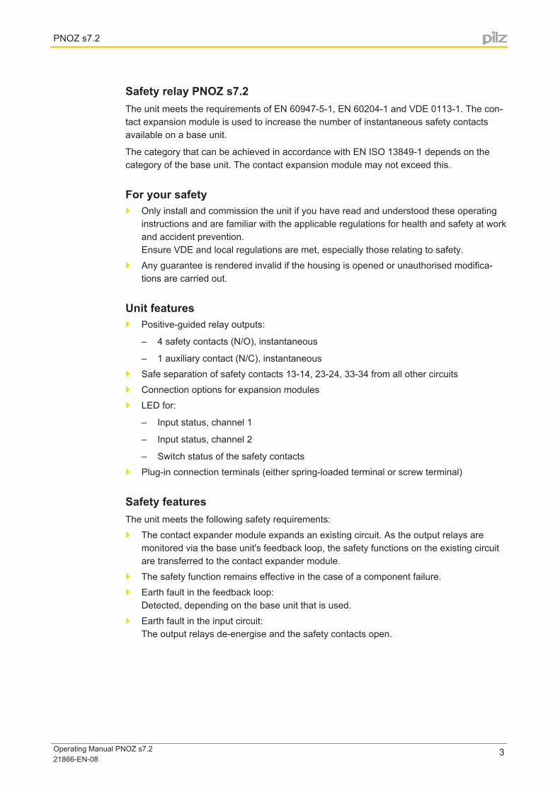
Safety relay PNOZ s7.2The unit meets the requirements of EN 60947-5-1, EN 60204-1 and VDE 0113-1. The con-tact expansion module is used to increase the number of instantaneous safety contacts available on a base unit.
The category that can be achieved in accordance with EN ISO 13849-1 depends on the category of the base unit. The contact expansion module may not exceed this.
For your safety} Only install and commission the unit if you have read and understood these operating
instructions and are familiar with the applicable regulations for health and safety at work and accident prevention. Ensure VDE and local regulations are met, especially those relating to safety.
} Any guarantee is rendered invalid if the housing is opened or unauthorised modifica-tions are carried out.
Unit features} Positive-guided relay outputs:
– 4 safety contacts (N/O), instantaneous
– 1 auxiliary contact (N/C), instantaneous} Safe separation of safety contacts 13-14, 23-24, 33-34 from all other circuits} Connection options for expansion modules} LED for:
– Input status, channel 1
– Input status, channel 2
– Switch status of the safety contacts} Plug-in connection terminals (either spring-loaded terminal or screw terminal)
Safety featuresThe unit meets the following safety requirements:} The contact expander module expands an existing circuit. As the output relays are
monitored via the base unit's feedback loop, the safety functions on the existing circuit are transferred to the contact expander module.
} The safety function remains effective in the case of a component failure.} Earth fault in the feedback loop:
Detected, depending on the base unit that is used.} Earth fault in the input circuit:
The output relays de-energise and the safety contacts open.
PNOZ s7.2
Operating Manual PNOZ s7.2 21866-EN-08
4
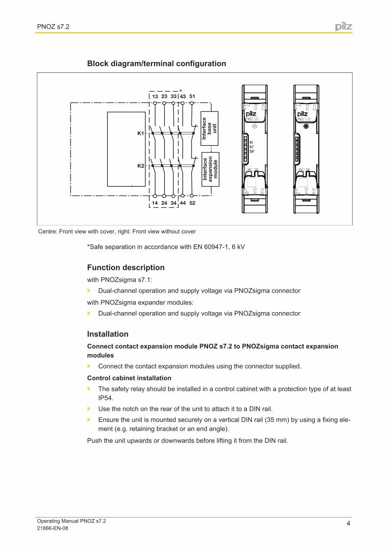
Block diagram/terminal configuration
� �
��
��
�� �� �� ��
�� �� ����
��
����
������
����
���
��
�
����
����
��
���
����
���
�
Centre: Front view with cover, right: Front view without cover
*Safe separation in accordance with EN 60947-1, 6 kV
Function descriptionwith PNOZsigma s7.1:} Dual-channel operation and supply voltage via PNOZsigma connector
with PNOZsigma expander modules:} Dual-channel operation and supply voltage via PNOZsigma connector
InstallationConnect contact expansion module PNOZ s7.2 to PNOZsigma contact expansion modules } Connect the contact expansion modules using the connector supplied.
Control cabinet installation} The safety relay should be installed in a control cabinet with a protection type of at least
IP54.} Use the notch on the rear of the unit to attach it to a DIN rail.} Ensure the unit is mounted securely on a vertical DIN rail (35 mm) by using a fixing ele-
ment (e.g. retaining bracket or an end angle).
Push the unit upwards or downwards before lifting it from the DIN rail.

PNOZ s7.2
Operating Manual PNOZ s7.2 21866-EN-08
5
Expansion options
Please note the max. power consumption of the contact expansion modules (see technical data PNOZ s7.1).
: Base unit
: Contact expansion module PNOZ s7.1
: Contact expansion module PNOZ s7.2
: Contact expansion module PNOZ s7.2 with ter-minator
: Base unit
: Contact expansion module PNOZ s7.1
: Contact expansion module PNOZ s7.2
: Expansion module PNOZ s7, s8, s9, s10, s11 as a terminator
: Contact expansion module PNOZ s7.1 with ter-minator
: Contact expansion module PNOZ s7.2
: Contact expansion module PNOZ s7.2 with ter-minator
PNOZ s7.2
Operating Manual PNOZ s7.2 21866-EN-08
6
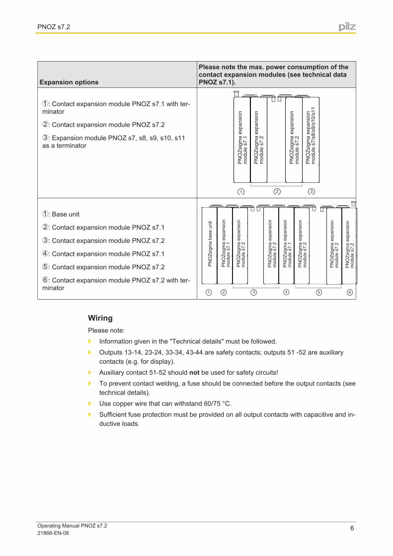
Expansion options
Please note the max. power consumption of the contact expansion modules (see technical data PNOZ s7.1).
: Contact expansion module PNOZ s7.1 with ter-minator
: Contact expansion module PNOZ s7.2
: Expansion module PNOZ s7, s8, s9, s10, s11 as a terminator
: Base unit
: Contact expansion module PNOZ s7.1
: Contact expansion module PNOZ s7.2
: Contact expansion module PNOZ s7.1
: Contact expansion module PNOZ s7.2
: Contact expansion module PNOZ s7.2 with ter-minator
WiringPlease note:} Information given in the "Technical details" must be followed.} Outputs 13-14, 23-24, 33-34, 43-44 are safety contacts; outputs 51 -52 are auxiliary
contacts (e.g. for display).} Auxiliary contact 51-52 should not be used for safety circuits!} To prevent contact welding, a fuse should be connected before the output contacts (see
technical details).} Use copper wire that can withstand 60/75 °C.} Sufficient fuse protection must be provided on all output contacts with capacitive and in-
ductive loads.

PNOZ s7.2
Operating Manual PNOZ s7.2 21866-EN-08
7
Preparing for operation} Supply voltage/input circuit/feedback loop
Supply voltage/input circuit/feedback loop
AC DC
Contact expansion module PNOZ s7.2
����
����
���������
�
������������ �� ���
������������ �� ���
OperationLEDs indicate the status and errors during operation:
LED on
Status indicators
In1 Channel 1 actuated.
In2 Channel 2 actuated.
In1, In2, Out Safety contacts are closed.
Faults - malfunctions} Contact malfunctions: If the contacts have welded, reactivation will not be possible after
the input circuit has opened.

PNOZ s7.2
Operating Manual PNOZ s7.2 21866-EN-08
8
Service life graphThe service life graphs indicate the number of cycles from which failures due to wear must be expected. The wear is mainly caused by the electrical load; the mechanical load is negli-gible.
Example} Inductive load: 0,2 A} Utilisation category: AC15} Contact service life: 2,000,000 cycles
Provided the application requires fewer than 2,000,000 cycles, the PFH value (see techni-cal details) can be used in the calculation.
To increase the service life, sufficient spark suppression must be provided on all output contacts. With capacitive loads, any power surges that occur must be noted. With contac-tors, use freewheel diodes for spark suppression.
PNOZ s7.2
Operating Manual PNOZ s7.2 21866-EN-08
9
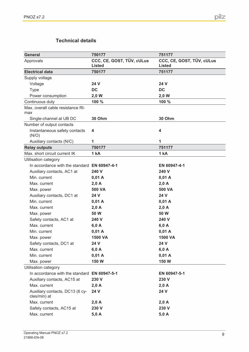
Technical details
General 750177 751177Approvals CCC, CE, GOST, TÜV, cULus
ListedCCC, CE, GOST, TÜV, cULus Listed
Electrical data 750177 751177Supply voltage
Voltage 24 V 24 VType DC DCPower consumption 2,0 W 2,0 W
Continuous duty 100 % 100 %Max. overall cable resistance Rl-max
Single-channel at UB DC 30 Ohm 30 OhmNumber of output contacts
Instantaneous safety contacts (N/O)
4 4
Auxiliary contacts (N/C) 1 1Relay outputs 750177 751177Max. short circuit current IK 1 kA 1 kAUtilisation category
In accordance with the standard EN 60947-4-1 EN 60947-4-1Auxiliary contacts, AC1 at 240 V 240 VMin. current 0,01 A 0,01 AMax. current 2,0 A 2,0 AMax. power 500 VA 500 VAAuxiliary contacts, DC1 at 24 V 24 VMin. current 0,01 A 0,01 AMax. current 2,0 A 2,0 AMax. power 50 W 50 WSafety contacts, AC1 at 240 V 240 VMax. current 6,0 A 6,0 AMin. current 0,01 A 0,01 AMax. power 1500 VA 1500 VASafety contacts, DC1 at 24 V 24 VMax. current 6,0 A 6,0 AMin. current 0,01 A 0,01 AMax. power 150 W 150 W
Utilisation categoryIn accordance with the standard EN 60947-5-1 EN 60947-5-1Auxiliary contacts, AC15 at 230 V 230 VMax. current 2,0 A 2,0 AAuxiliary contacts, DC13 (6 cy-cles/min) at
24 V 24 V
Max. current 2,0 A 2,0 ASafety contacts, AC15 at 230 V 230 VMax. current 5,0 A 5,0 A
PNOZ s7.2
Operating Manual PNOZ s7.2 21866-EN-08
10
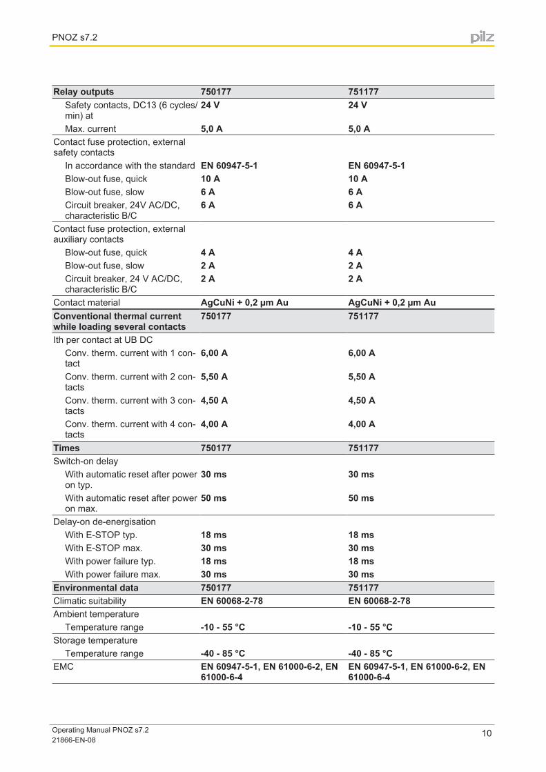
Relay outputs 750177 751177Safety contacts, DC13 (6 cycles/min) at
24 V 24 V
Max. current 5,0 A 5,0 AContact fuse protection, external safety contacts
In accordance with the standard EN 60947-5-1 EN 60947-5-1Blow-out fuse, quick 10 A 10 ABlow-out fuse, slow 6 A 6 ACircuit breaker, 24V AC/DC, characteristic B/C
6 A 6 A
Contact fuse protection, external auxiliary contacts
Blow-out fuse, quick 4 A 4 ABlow-out fuse, slow 2 A 2 ACircuit breaker, 24 V AC/DC, characteristic B/C
2 A 2 A
Contact material AgCuNi + 0,2 µm Au AgCuNi + 0,2 µm AuConventional thermal current while loading several contacts
750177 751177
Ith per contact at UB DCConv. therm. current with 1 con-tact
6,00 A 6,00 A
Conv. therm. current with 2 con-tacts
5,50 A 5,50 A
Conv. therm. current with 3 con-tacts
4,50 A 4,50 A
Conv. therm. current with 4 con-tacts
4,00 A 4,00 A
Times 750177 751177Switch-on delay
With automatic reset after power on typ.
30 ms 30 ms
With automatic reset after power on max.
50 ms 50 ms
Delay-on de-energisationWith E-STOP typ. 18 ms 18 msWith E-STOP max. 30 ms 30 msWith power failure typ. 18 ms 18 msWith power failure max. 30 ms 30 ms
Environmental data 750177 751177Climatic suitability EN 60068-2-78 EN 60068-2-78Ambient temperature
Temperature range -10 - 55 °C -10 - 55 °CStorage temperature
Temperature range -40 - 85 °C -40 - 85 °CEMC EN 60947-5-1, EN 61000-6-2, EN
61000-6-4EN 60947-5-1, EN 61000-6-2, EN 61000-6-4

PNOZ s7.2
Operating Manual PNOZ s7.2 21866-EN-08
11
Environmental data 750177 751177Vibration
In accordance with the standard EN 60068-2-6 EN 60068-2-6Frequency 10,0 - 55,0 Hz 10,0 - 55,0 HzMax. amplitude 0,35 mm 0,35 mm
Airgap creepageIn accordance with the standard EN 60947-1 EN 60947-1Overvoltage category III IIIPollution degree 2 2
Rated insulation voltage 250 V 250 VRated impulse withstand voltage 6,00 kV 6,00 kVProtection type
Mounting (e.g. cabinet) IP54 IP54Housing IP40 IP40Terminals IP20 IP20
Mechanical data 750177 751177Mounting position Any AnyMechanical life 10,000,000 cycles 10,000,000 cyclesMaterial
Bottom PC PCFront PC PCTop PC PC
Cross section of external conduc-tors with screw terminals
1 core flexible 0,25 - 2,50 mm², 24 - 12 AWG –2 core with the same cross sec-tion, flexible with crimp connec-tors, no plastic sleeve
0,25 - 1,00 mm², 24 - 16 AWG –
2 core with the same cross sec-tion, flexible without crimp con-nectors or with TWIN crimp con-nectors
0,20 - 1,50 mm², 24 - 16 AWG –
Torque setting with screw terminals 0,50 Nm –Connection type Screw terminal Cage clamp terminalMounting type plug in plug inCross section of external conduc-tors with spring-loaded terminals: flexible with/without crimp connec-tor
– 0,20 - 2,50 mm², 24 - 12 AWG
Spring-loaded terminals: Terminal points per connection
– 2
Stripping length – 9 mmDimensions
Height 98,0 mm 100,0 mmWidth 17,5 mm 17,5 mmDepth 120,0 mm 120,0 mm
Weight 170 g 170 g
The standards current on 2009-12 apply.

PNOZ s7.2
Operating Manual PNOZ s7.2 21866-EN-08
12
Safety characteristic data
Operating mode
EN ISO 13849-1: 2006PL
EN ISO 13849-1: 2006Category
EN IEC 62061SIL CL
EN IEC 62061PFHD [1/h]
IEC 61511SIL
IEC 61511PFD
EN ISO 13849-1: 2006TM [year]
Safety con-tacts, instan-taneous
PL e Cat. 4 SIL CL 3 2,31E-09 SIL 3 2,03E-06 20
All the units used within a safety function must be considered when calculating the safety characteristic data.
Information
A safety function's SIL/PL values are not identical to the SIL/PL values of the units that are used and may be different. We recommend that you use the PAScal software tool to calculate the safety function's SIL/PL values.
ATTENTION!
It is essential to consider the relay's service life graphs. The relay outputs' safety-related characteristic data is only valid if the values in the service life graphs are met.
The PFH value depends on the switching frequency and the load on the relay output. If the service life graphs are not accessible, the stated PFH value can be used irrespective of the switching frequency and the load, as the PFH value already considers the relay's B10d val-ue as well as the failure rates of the other components.
Order reference
Order reference
Product type Features TerminalsOrder no.
PNOZ s7.2 24 V DC Screw terminals 750 177
PNOZ s7.2 C 24 V DC Spring-loaded terminals 751 177
EC declaration of conformityThis product/these products meet the requirements of the directive 2006/42/EC for machin-ery of the European Parliament and of the Council. The complete EC Declaration of Con-formity is available on the Internet at www.pilz.com/downloads. Representative: Norbert Fröhlich, Pilz GmbH & Co. KG, Felix-Wankel-Str. 2, 73760 Ostfil-dern, Germany
...
Sac
hnum
mer
Prin
ted
in G
erm
any
©
Pilz
Gm
bH &
Co.
KG
, 201
1
+49 711 [email protected]
Pilz GmbH & Co. KGFelix-Wankel-Straße 273760 Ostfildern, GermanyTelephone: +49 711 3409-0Telefax: +49 711 3409-133E-Mail: [email protected]: www.pilz.com
Technical supportIn many countries we are represented by our subsidiaries and sales partners.
Please refer to our homepage for further details or contact our headquarters.
Indu
raN
ET
p®, P
ilz®, P
IT®, P
MC
prot
ego®
, PM
I®, P
NO
Z®, P
rimo®
, PS
EN
®, P
SS
®, P
VIS
®, S
afet
yBU
S p
®, S
afet
yEY
E®, S
afet
yNE
T p®
, the
spi
rit o
f saf
ety®
are
reg
iste
red
and
prot
ecte
d tr
adem
arks
of
Pilz
Gm
bH &
Co.
KG
in s
ome
coun
trie
s. W
e w
ould
poi
nt o
ut th
at p
rodu
ct fe
atur
es m
ay v
ary
from
the
deta
ils s
tate
d in
this
doc
umen
t, de
pend
ing
on th
e st
atus
at t
he ti
me
of p
ublic
atio
n an
d th
e sc
ope
of th
e eq
uipm
ent.
We
acce
pt n
o re
spon
sibi
lity
for
the
valid
ity, a
ccur
acy
and
entir
ety
of th
e te
xt a
nd g
raph
ics
pres
ente
d in
this
info
rmat
ion.
Ple
ase
cont
act o
ur T
echn
ical
Sup
port
if y
ou h
ave
any
ques
tions
.
2186
6-E
N-0
8, 2
013-
05 P
rinte
d in
Ger
man
y ©
Pilz
Gm
bH &
Co.
KG
, 201
1
Back cover