B777-300ER, REGISTRATION 9V-SWB ENGINE FIRE...
46
FINAL REPORT B777-300ER, REGISTRATION 9V-SWB ENGINE FIRE 27 JUNE 2016 AIB/AAI/CAS.122 Transport Safety Investigation Bureau Ministry of Transport Singapore 27 FEBRUARY 2017
Transcript of B777-300ER, REGISTRATION 9V-SWB ENGINE FIRE...

FINAL REPORT
B777-300ER, REGISTRATION 9V-SWB
ENGINE FIRE
27 JUNE 2016
AIB/AAI/CAS.122
Transport Safety Investigation Bureau Ministry of Transport
Singapore
27 FEBRUARY 2017
1 © 2017 Government of Singapore
The Transport Safety Investigation Bureau
The Transport Safety Investigation Bureau (TSIB) is the air and marine accidents and incidents investigation authority in Singapore responsible to the Ministry of Transport. Its mission is to promote aviation and marine safety through the conduct of independent and objective investigations into air and marine accidents and incidents. For aviation related investigations, the TSIB conducts the investigations in accordance with the Singapore Air Navigation (Investigation of Accidents and Incidents) Order 2003 and Annex 13 to the Convention on International Civil Aviation, which governs how member States of the International Civil Aviation Organisation (ICAO) conduct aircraft accident investigations internationally. In carrying out the investigations, the TSIB will adhere to ICAO’s stated objective, which is as follows:
“The sole objective of the investigation of an accident or incident shall be the prevention of accidents or incidents. It is not the purpose of this activity to apportion blame or liability.”
Accordingly, it is inappropriate that TSIB reports should be used to assign fault or blame or determine liability, since neither the investigation nor the reporting process has been undertaken for that purpose.
2 © 2017 Government of Singapore
CONTENTS
Page
GLOSSARY OF ABBREVIATIONS 3 SYNOPSIS
AIRCRAFT DETAIL
4
4
1 FACTUAL INFORMATION 5 1.1 History of the flight 5 1.2 Damage to aircraft 8 1.3 Other damages 15 1.4
1.5 Recorded data Fire
16 16
1.6 Test and research 18 1.7 Additional information on MFOHE 20
2 ANALYSIS 26
2.1 Fuel leakage into engine oil system 26 2.2 Fire initiation and propagation 29 2.3 Fire detection 30 2.4 Detection for fuel leaking into oil system 31 2.5 Design of MFOHE 32 2.6 Service bulletin to resolve cracked tube problem 33 2.7 Execution of FUEL DISAGREE checklist 33 2.8 Decision to return to Singapore 34 2.9 Decision regarding evacuation 34 3 CONCLUSION 37 4 SAFETY ACTIONS 38 5 SAFETY RECOMMENDATIONS 40 Appendix 1
3 © 2017 Government of Singapore
GLOSSARY OF ABBREVIATIONS
ACARS Aircraft Communication and Reporting System AMM Aircraft Maintenance Manual ARFF Airport Rescue and Firefighting Service ATC Air Traffic Control CAAM Continued Airworthiness Assessment Methodologies CVT Centre Vent Tube CVR Cockpit Voice Recorder EICAS Engine Indicating and Crew Alerting System FAA Federal Aviation Administration FC Fire Commander FDR Flight Data Recorder HPC High Pressure Compressor IFS In-flight Supervisor IGV Inlet Guide Vane LT Local Time MFOHE Main Fuel Oil Heat Exchanger PIC Pilot-in-command QAR Quick Access Recorder RET Rapid Exit Taxiway SATCOM Satellite Communication SB Service Bulletin TR Thrust Reverser UTC Coordinated Universal Time VBV Variable Bleed Valve
4 © 2017 Government of Singapore
SYNOPSIS
On 27 June 2016, a Boeing 777-300ER aircraft departed Singapore for Milan. About two hours into the flight, the right engine indication showed a low oil quantity and subsequently, the flight crew felt a vibration in the control column and cockpit floor. The flight crew decided to return to Singapore.
Shortly after landing in Changi Airport, a fire was observed to have occurred
in the vicinity of the aircraft’s right engine. After the aircraft came to a stop on the runway, a fire developed under the right wing. The airport rescue and firefighting service, which was already on standby, responded promptly and the fire was extinguished. All persons on board the aircraft disembarked via a mobile stairs.
Damage to the aircraft included heat damage to the core of the engine,
portions of the engine cowlings, the wing area directly behind and outboard of the right hand engine. There was no injury to any person in this occurrence.
The occurrence was classified as an accident.
AIRCRAFT DETAILS Aircraft type : Boeing B777-300ER Operator : Singapore Airlines Aircraft registration : 9V-SWB Numbers and type of engines : 2 x GE90-115B Date and time of incident : 27 June 2016, 0649 hours (Local Time) Location of occurrence : Changi Airport, Runway 20C Type of flight : Scheduled passenger flight Persons on board : 241

5 © 2017 Government of Singapore
1 FACTUAL INFORMATION All times used in this report are Singapore time. Singapore time is eight hours ahead of Coordinated Universal Time (UTC).
1.1 History of the flight 1.1.1 A Boeing 777-300ER aircraft departed Singapore Changi Airport at 0224
hrs for Milan on 27 June 2016. The aircraft carried two sets of operating crew, i.e. four pilots in total.
1.1.2 As the aircraft was climbing to its cruising altitude, the flight crew encountered weather which required them to perform weather avoidance manoeuvres. About 30 minutes into the flight, when the aircraft had climbed to 30,000 feet, the flight crew noticed that the oil quantity parameter in the Engine Indicating and Crew Alerting System (EICAS) showed 17 units for the left engine but only 1 unit for the right engine. The flight crew also noticed from the EICAS display that the right engine oil pressure was fluctuating between 65 and 70 psi while the oil temperature for the right engine was 10°C higher than the left engine. However, both the oil pressure and temperature parameters were within the normal operating range1.
1.1.3 The flight crew looked through their available manuals but was unable to
find an appropriate procedure that addressed the low engine oil quantity situation.
1.1.4 At 0304 hrs, the Pilot-in-command (PIC) contacted their company’s
engineering control centre for assistance via satellite communication (SATCOM). The PIC informed the engineer on duty of the engine parameters and asked if it was safe to continue with the flight. The engineer informed the PIC that since the oil pressure was within the normal operating range, there could be a faulty oil quantity indication. The engineer advised the PIC to continue with the flight but monitor the right engine oil parameters. The engineer told the PIC that he would also contact the company’s technical services personnel for advice.
1.1.5 After being briefed by the engineer on the situation, the technical services
personnel believed that it was a faulty oil quantity indication. As the aircraft had just departed and was not far from Singapore, the technical services personnel recommended that the aircraft return to Singapore.
1.1.6 According to the flight crew, as they were passing waypoint VPG at
approximately 0320 hrs, the First Officer performed a routine fuel quantity
1 In general, when there is a typical oil leakage situation, the oil quantity will decrease. At a sufficiently low
quantity, there may be a noticeable increase in oil temperature and eventually, a noticeable decrease in oil
pressure.

6 © 2017 Government of Singapore
check. After comparing the TOTALIZER fuel quantity2 with the planned fuel remaining quantity3, it was determined that the fuel consumption was better than expected as the fuel on board was 600 kg more than the expected value.
1.1.7 At 0328 hrs, the engineer sent a message via the Aircraft Communication
and Reporting System (ACARS) to the flight crew informing them about the recommendation by the technical services personnel for the aircraft to return to Singapore and requesting them to contact the engineering control centre.
1.1.8 The PIC contacted the engineering control centre and a conference call
among the PIC, the engineering control centre and the technical services personnel was held, which lasted for about 20 minutes. The PIC informed the rest that the flight crew had been monitoring the right engine oil parameters for 50 minutes and other than the indicated low oil quantity, the parameters appeared normal. It was jointly assessed that the flight could continue to Milan with the proviso that the flight crew monitor the right engine oil parameters and contact the engineering control centre for assistance if needed.
1.1.9 Shortly after the conference call ended, the flight crew felt an unusual vibration in the control column and cockpit floor. The flight crew tried to diagnose the problem by changing the engine power settings and found that the vibration disappeared when the power of the right engine was reduced. At about the same time, the flight crew caught a momentary wisp of burnt smell in the cockpit but the smell disappeared quickly.
1.1.10 At 0404 hrs, the PIC informed the engineering control centre about the vibrations which the flight crew experienced whenever the right engine was operated at higher power settings. In the ensuing conference call among the PIC, the engineering control centre and the technical services personnel, it was assessed that there was no need to shut down the right engine and decided that the aircraft would return to Singapore with the right engine operating at idle power. In the midst of the conference call, the In-flight supervisor (IFS) informed the flight crew that there was a burnt smell detected in the cabin. In response, the flight crew turned off the right engine bleed system4.
1.1.11 According to the cabin crew, the smell was particularly strong in the business class cabin, in the forward part of the aircraft. The cabin crew distributed wet towels for the passengers to hold over their nose and breathe through it.
2 The TOTALIZER fuel quantity is the remaining quantity of fuel determined by the fuel quantity indicating
system. The quantity is calculated based on feedback from sensors in the fuel tanks. 3 The planned fuel remaining quantity is the expected amount of fuel remaining at various waypoints based on
the expected fuel consumption taking the flight plan into consideration. 4 The engine bleed system routes air from the compressor section of the engine for various uses, including air
conditioning.

7 © 2017 Government of Singapore
1.1.12 After the conference call ended, the flight crew reduced the right engine to idle power and proceeded to turn the aircraft around to return to Singapore. For the return journey to Singapore, the flight crew adopted the procedure for single engine operation, including a descent to 17,000 feet before reducing the right engine to idle power.
1.1.13 When the IFS informed the flight crew that the burnt smell in the cabin was still present, the right air conditioning pack and recirculating fans were switched off. Shortly after, the smell in the cabin subsided.
1.1.14 At 0521 hrs, the flight crew received a FUEL DISAGREE message on the EICAS. The flight crew performed the FUEL DISAGREE checklist. The FUEL DISAGREE checklist suggested four scenarios in which a fuel leak should be suspected and when the flight crew should perform the FUEL LEAK checklist. One such scenario is when the TOTALIZER fuel quantity is less than the CALCULATED5 fuel quantity.
1.1.15 The flight crew observed from the display of the flight management system that TOTALIZER fuel quantity was about 79 tonnes and the CALCULATED fuel quantity was about 83 tonnes.
1.1.16 However, the flight crew did not perform the FUEL LEAK checklist. According to the flight crew, they believed the CALCULATED fuel quantity was no longer accurate in view of the following:
(a) Input changes had been made to the flight management system after the right engine was set to idle power6.
(b) They were no longer on the planned flight route. (c) They had 600 kg more fuel than expected when they last performed a
routine fuel check (see paragraph 1.1.6).
1.1.17 Thus, the flight crew performed their own fuel calculation by subtracting the amount of fuel consumed from the total amount of fuel at the start of the flight. The fuel consumed was calculated by multiplying an average fuel flow value (that the flight crew determined) by the duration of the flight. They arrived at a figure of about 79 tonnes. As this tallied well with the TOTALIZER fuel quantity figure, the flight crew concluded that the FUEL DISAGREE message was a spurious one and that there was no need to proceed with the FUEL LEAK checklist.
5 The CALCULATED fuel quantity is determined by the flight management computer by subtracting the fuel
used (calculated basing on fuel flow figures as measured by sensors in the engines) from the total fuel
quantity at the start of the flight. 6 As there was no option on the flight management system to reflect that the right engine was operating at idle
power, the flight crew decided to select the option indicating that one engine was inoperative. This was to
configure the flight management system to compute navigational and performance parameters based on single
engine operation.

8 © 2017 Government of Singapore
1.1.18 Several times on the return journey and as the aircraft approached Singapore, the flight crew was queried by the Air Traffic Control (ATC) if they needed any assistance. The flight crew replied that, other than the need to fly at the lower altitude of 17,000 feet, no assistance was needed as all other operations were normal.
1.1.19 Prior to landing, the flight crew jettisoned about 41,500 kg of fuel to bring the aircraft to below its maximum landing weight.
1.1.20 At 0649 hrs, the aircraft landed on the runway. About 20 seconds after
the thrust reversers on both engines were deployed, the occupants in the cabin heard two loud bangs, accompanied by two flashes, originating from the right engine area. At the same time, the flight crew heard a soft thud. The Airport Rescue and Firefighting Service (ARFF) personnel who were monitoring the aircraft’s arrival informed the Control Tower on seeing the fire at the right engine. The Control Tower informed the flight crew of the fire and instructed the aircraft to stop at the intersection between the runway and rapid exit taxiway E7. The flight crew did not receive any fire warning in the cockpit.
1.1.21 The ARFF which was on standby with four foam tenders and one water tender, entered the runway as soon as clearance to enter the runway was given by the Control Tower. The first foam tender arrived on scene after 57 seconds and started discharging foam at the right engine.
1.1.22 The fire was eventually brought under control (more on firefighting in paragraph 1.5). Disembarkation commenced at 0710 hrs via a mobile stairs positioned at the front left door of the aircraft. All occupants, including the flight crew, vacated the aircraft by 0731 hrs.
1.2 Damage to aircraft
1.2.1 The right wing and engine area of the aircraft sustained extensive damage. There was no damage to the fuselage and the left wing, nor to the windows in the area of fuselage closest to the fire.
1.2.2 Right wing area
1.2.2.1 The most extensive damage to the right wing was in the vicinity of the right engine. Fire damage was also observed on the underside of the right wing, outboard of the engine.
1.2.2.2 Details of the damage to the right wing can be found in Appendix 1. 1.2.3 Engine area
1.2.3.1 Damage to the right engine area includes (hereinafter the clock position
references in this report refer to the aft-looking-forward direction):

9 © 2017 Government of Singapore
• Heat damage and delamination of the outboard thrust reverser (TR) cowl external surfaces from 4 to 6 o’clock position (Figure 1)
Figure 1: Right engine outboard fan cowl and TR forward cowling
• Heat damage to the outboard TR aft cowl (Figure 2)
Figure 2: Outboard TR aft cowl
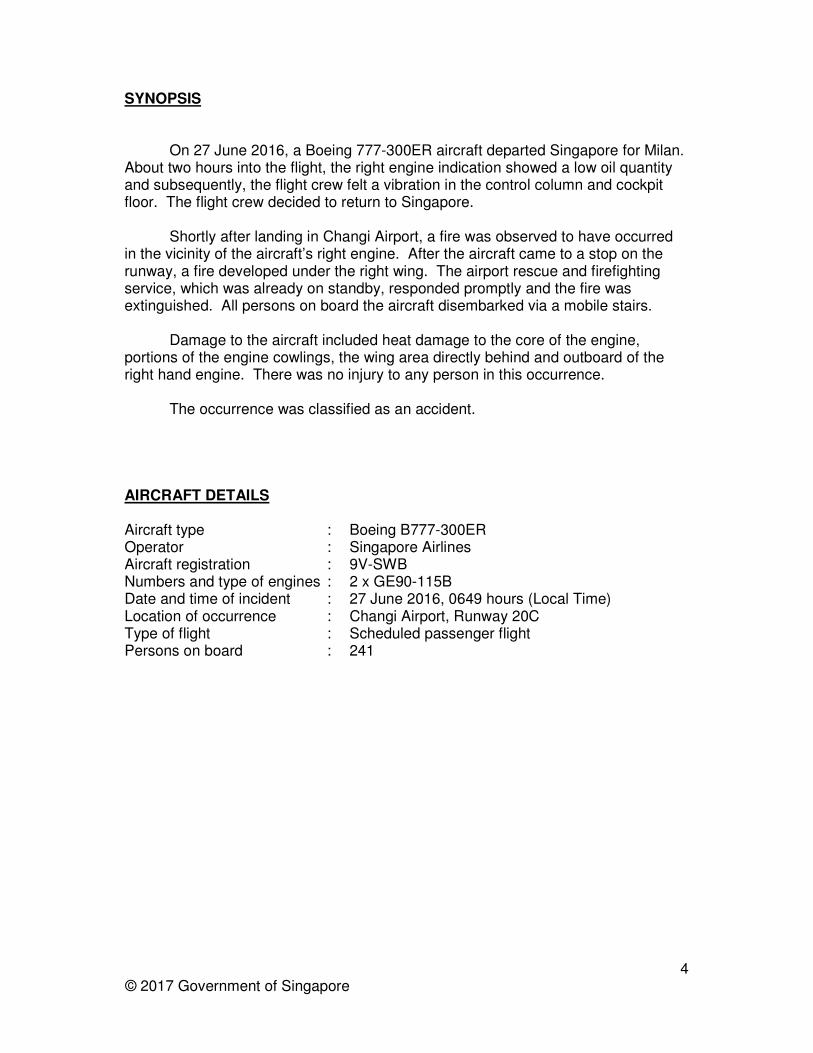
• Heat damage to the TR fan duct inner and outer walls and significant delamination to the outer wall trailing edge surfaces (Figure 3)
10 © 2017 Government of Singapore
Figure 3: Delamination of the inboard TR fan duct walls
• Heat damage observed on all eight inboard TR blocker doors
• Heat damage to the four upper inboard TR blocker door links
• Four lower inboard TR blocker door links sustained heat damage and were severed 3-4 inches above the blocker doors
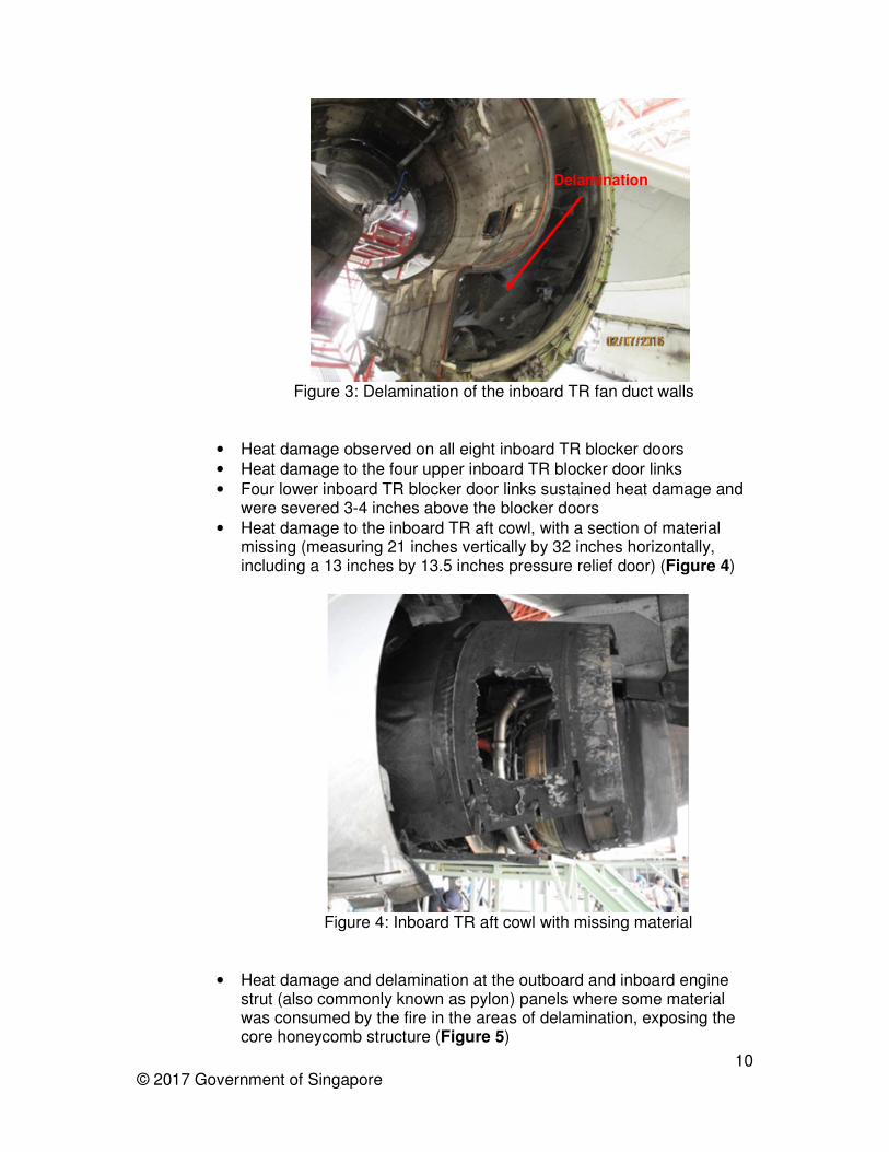
• Heat damage to the inboard TR aft cowl, with a section of material missing (measuring 21 inches vertically by 32 inches horizontally, including a 13 inches by 13.5 inches pressure relief door) (Figure 4)
Figure 4: Inboard TR aft cowl with missing material
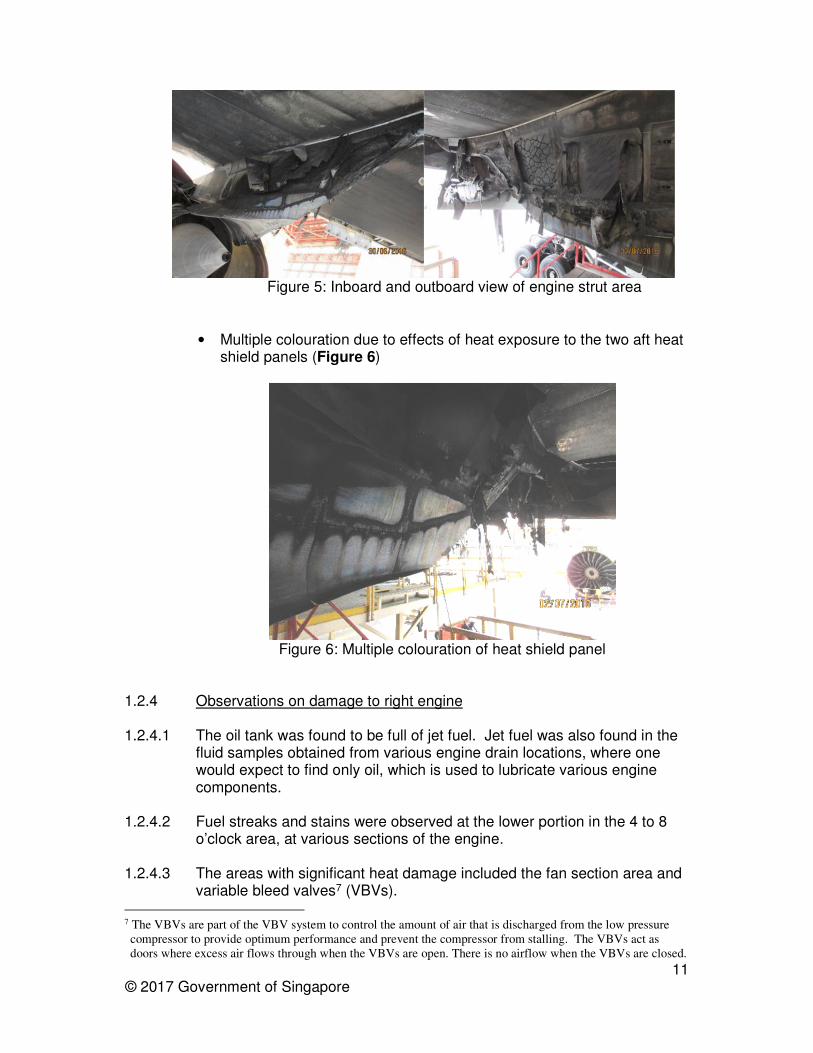
• Heat damage and delamination at the outboard and inboard engine strut (also commonly known as pylon) panels where some material was consumed by the fire in the areas of delamination, exposing the core honeycomb structure (Figure 5)
Delamination
11 © 2017 Government of Singapore
Figure 5: Inboard and outboard view of engine strut area
• Multiple colouration due to effects of heat exposure to the two aft heat shield panels (Figure 6)
Figure 6: Multiple colouration of heat shield panel
1.2.4 Observations on damage to right engine 1.2.4.1 The oil tank was found to be full of jet fuel. Jet fuel was also found in the
fluid samples obtained from various engine drain locations, where one would expect to find only oil, which is used to lubricate various engine components.
1.2.4.2 Fuel streaks and stains were observed at the lower portion in the 4 to 8 o’clock area, at various sections of the engine.
1.2.4.3 The areas with significant heat damage included the fan section area and
variable bleed valves7 (VBVs).
7 The VBVs are part of the VBV system to control the amount of air that is discharged from the low pressure
compressor to provide optimum performance and prevent the compressor from stalling. The VBVs act as
doors where excess air flows through when the VBVs are open. There is no airflow when the VBVs are closed.

12 © 2017 Government of Singapore
1.2.4.4 In the fan section area, heat damage was observed in the 5 to 10 o’clock area of the following areas (Figure 7):
• Fan shroud area with the most significant damage in the 7 to 9 o’clock area
• Outer aft acoustic panels, made of composite material, where the resin material was burnt, leaving the fabric delaminated and loose
• Inner barrel acoustic panels, made of composite material, with the most severe damage in the 6 to 8 o’clock area where the resin material was burnt, leaving the fabric delaminated and loose
• Blistering and fractures on the outlet guide vanes (OGVs)
• Outer inter-vane fairings displayed blistering and distortion, with the most affected region in the 6:30 to 8 o’clock area
Figure 7: Occurrence engine forward looking aft view
Fan shroud damage at
7:30 location
Typical view of delaminated and separated inner barrel
acoustic panel
Blistered and deformed outer inter-
vane fairings
Heat damage in fan section 5 to 10 o’clock area (position based on aft looking forward orientation)
13 © 2017 Government of Singapore
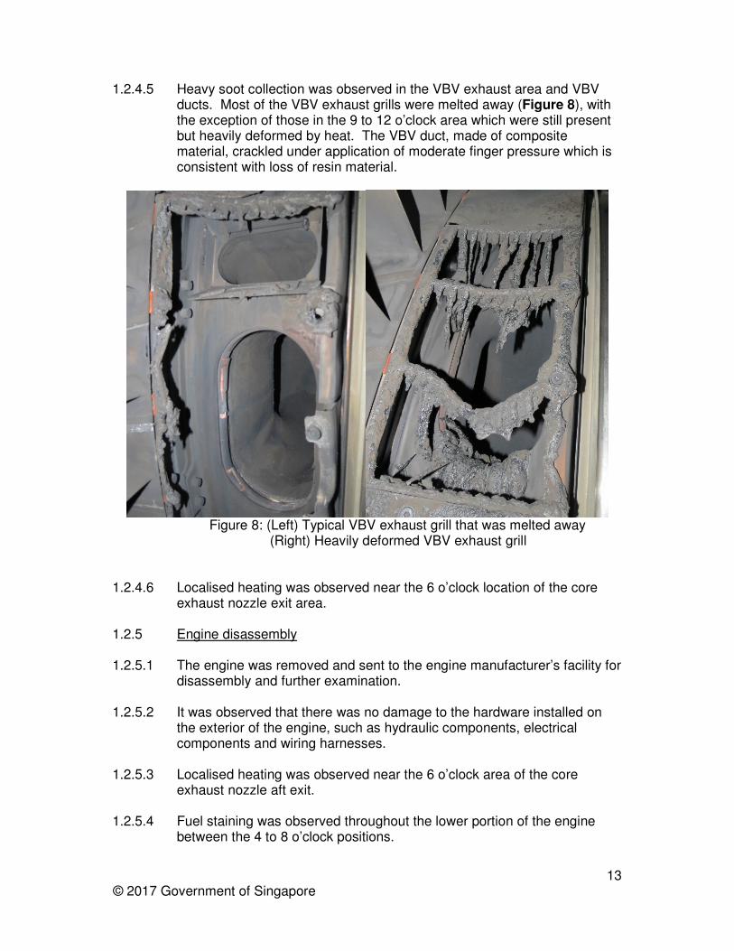
1.2.4.5 Heavy soot collection was observed in the VBV exhaust area and VBV ducts. Most of the VBV exhaust grills were melted away (Figure 8), with the exception of those in the 9 to 12 o’clock area which were still present but heavily deformed by heat. The VBV duct, made of composite material, crackled under application of moderate finger pressure which is consistent with loss of resin material.
Figure 8: (Left) Typical VBV exhaust grill that was melted away
(Right) Heavily deformed VBV exhaust grill
1.2.4.6 Localised heating was observed near the 6 o’clock location of the core
exhaust nozzle exit area. 1.2.5 Engine disassembly
1.2.5.1 The engine was removed and sent to the engine manufacturer’s facility for
disassembly and further examination.
1.2.5.2 It was observed that there was no damage to the hardware installed on the exterior of the engine, such as hydraulic components, electrical components and wiring harnesses.
1.2.5.3 Localised heating was observed near the 6 o’clock area of the core exhaust nozzle aft exit.
1.2.5.4 Fuel staining was observed throughout the lower portion of the engine between the 4 to 8 o’clock positions.

14 © 2017 Government of Singapore
1.2.5.5 The following components which were lubricated by the engine oil system were found to be dry and discoloured:
• All engine bearings8
• Gears of the accessory gearbox
• Bevel gears of the inlet gearbox
1.2.5.6 Jet fuel was also found in the booster spool cavity9. During the initial examination of the engine, the level of the jet fuel collected was up to the rear flange of the booster spool (Figure 9).
Figure 9: Observations with reference to the cross section view of the engine
1.2.5.7 Heat damage was observed at the inlet guide vanes (IGV) of the high pressure compressor (HPC). Three IGVs which were installed at the 6 o’clock position were found separated due to melting near the inner trunnion which holds these IGVs in position (Figure 10). Several IGVs also exhibited signs of heat damage.
8 The main function of the bearings is to support the rotating shafts of the engine. They are housed in three
engine sumps which are designed to ensure proper lubrication and cooling of the bearings. 9 The booster spool is also commonly known as the low pressure compressor (LPC). The booster spool cavity is
a void that is usually not filled with any liquid. It is within the structure that houses the low pressure
compressor rotor blades.
Level of jet fuel in the booster spool cavity
Rear flange of booster cavity
Three IGVs that were separated from their trunnion were at the 6 o’clock position
Decreasing level of soot collection on HPC rotors towards the aft

15 © 2017 Government of Singapore
Figure 10: Damage to IGVs
1.2.5.8 In the high pressure compressor (HPC), the heaviest evidence of soot
collection was observed at the stage 1 rotor with decreasing level of soot collection towards the aft of the HPC (refer to Figure 9).
1.2.5.9 Localised discolouration due to high temperature exposure was observed at a section of the core exhaust nozzle, behind the feature known as the turkey feather seal10 (Figure 11).
Figure 11: Core exhaust nozzle
1.3 Other damages
1.3.1 A patch of the runway about 2.5 m by 1.5 m was damaged by fire fuelled by a pool of jet fuel on the ground.
10 The turkey feather seal is designed to be a fire seal. Its purpose is to prevent flames of a fire under the engine
cowling, from exiting the core compartment in the top quadrant of the engine, where it could reach the
underside of the wing and fuel tank.
Three IGVs that were separated
Typical heat damage to IGVs
Area exposed to high temperature resulting in discolouration
Turkey feather seal

16 © 2017 Government of Singapore
1.4 Recorded data 1.4.1 The aircraft’s flight data recorder (FDR) was downloaded. The FDR data
was of good quality. 1.4.2 The FDR did not record any fire warning during the entire event. 1.4.3 The data downloaded from the cockpit voice recorder (CVR) comprised
three channels of 30 minutes high quality audio recording and two channels of 120 minutes standard quality audio recording. The CVR data included the conversations that took place during the fire occurrence.
1.4.4 The aircraft’s quick access recorder (QAR) data was provided by the
operator. It contained recorded parameters from the occurrence flight and several prior flights.
1.4.5 Video footages from surveillance cameras installed around the runway
were provided by the airport operator. Video footages from video recording devices installed within the firefighting vehicles were provided by the ARFF. The video footages provided to this investigation were useful in establishing the sequence of events for this occurrence.
1.5 Fire 1.5.1 When responding to the fire, the Fire Commander (FC) of the ARFF
requested the Control Tower to ask the flight crew to switch the aircraft radio to the emergency channel for communication between the FC and flight crew.
1.5.2 Subsequently, the FC and PIC established communication on the emergency channel and the key exchanges were as follows:
Time Party
Speaking Content
06:51:50 PIC how is it looking…Is the fire contained
06:51:53 FC …we are still trying to contain the fire…the fire is pretty big…will like to advise… disembarkation11 on your port side
06:52:05 PIC Okay evacuate12 from the port side confirm
11 The FC was confident that the ARFF would be able to bring the fire under control and the occupants of the
aircraft could then disembark from the aircraft. According to the FC, he knew the difference between
evacuation (via escape slides) and disembarkation (via stairs). He specifically used the term
“disembarkation” as he did not think that an evacuation was necessary. 12 According to the PIC, he knew the difference between evacuation and disembarkation. He was trying to ask
the FC for input on the evacuation aspect.

17 © 2017 Government of Singapore
06:52:09 FC …still trying to contain the fire…still some random fire on your right hand engine but we are keeping it under control13
06:52:24 PIC …do you need us to evacuate from the port side
06:52:29 FC …Singapore 368 standby14 standby
06:52:33 PIC Okay standby for your instructions Singapore 368 standby for your instructions
1.5.3 Jet fuel that was discharged from the right engine onto the tarmac fuelled
a fire that impinged on the underside of the right wing near the right engine area.
1.5.4 The ARFF managed to bring the fire under control and put out the visible fire in the right engine area and on the ground at 0653 hrs. However, ARFF personnel, using infra-red detector, found heat signature within the internal section of the engine and they continued to monitor the situation. The key exchanges between the FC and PIC at that point were as follows:
Time Party
Speaking Content
06:54:08 FC …we have kept the fire under control. We will like to advise disembarkation on your port side
06:54:20 PIC okay you want us to disembark through the slides or are you going to provide mobile stairs
06:54:38 FC …we will like to advise disembarkation on your on your port side
06:54:48 PIC okay you want us to disembark on the port side through the emergency slides can you confirm that
06:55:14 PIC …can you just confirm that we need to evacuate through the left through the emergency slides
06:55:33 FC negative negative negative we will like to advise disembarkation disembarkation no evacuation no evacuation
06:55:42 PIC okay disembarkation through mobile steps understand understand…
13 According to the FC, when he mentioned that the fire was under control, it was based on his assessment that
there was no risk of the fire spreading. 14 The FC said the reason he asked the PIC to stand by was that he was on the left side of the aircraft where his
view of the fire was blocked by the fuselage, and he decided to move to the right side of the aircraft to
reassess the situation before giving the PIC a reply.

18 © 2017 Government of Singapore
1.5.5 About three minutes later, the fire appeared again at the forward section of the right engine. It was immediately put out by the ARFF.
1.5.6 There was no fire warning in cockpit when the flight crew were informed of
the ongoing fire by the FC. The flight crew eventually discharged both the bottles of fire extinguishing agent into the right engine when they were queried by the FC if they had discharged the bottles.
1.5.7 Eventually, after the FC had assessed the situation to be safe, the
occupants of the aircraft disembarked via a mobile stairs.
1.5.8 According to the PIC, on being informed that there was an engine fire, he was mentally prepared to initiate an evacuation via the escape slides, even though there was no indication of fire in the cockpit. To prepare for the evacuation, he instructed the cabin crew members to position themselves at the doors as soon as the aircraft came to a stop.
1.5.9 During the initial stages of the fire, several cabin crew members tried to
contact the flight crew through the cabin interphone. However, only one call was answered by a flight crew member and he informed the cabin crew that they were aware of the situation and were handling it.
1.5.10 According to one of the cabin crew members interviewed, during the initial
stage of the fire, heat was felt in the cabin wall at the section of the fuselage closest to the fire. She informed the Chief Steward who then informed the IFS. The IFS could not recall whether this piece of information was conveyed to the flight crew.
1.5.11 According to the PIC, the flight crew were aware that cabin crew members
were a source of information throughout the occurrence. However, the flight crew were not able to attend to every call from the cabin crew as they had to prioritise their tasks. In terms of obtaining information on the fire, they gave priority to the task of communicating with the FC as he was the subject matter expert and would have a better assessment of the fire from his location outside the aircraft.
1.6 Test and research
1.6.1 MFOHE Examination
1.6.1.1 As fuel was found in the booster spool cavity, oil tank, all bearing sumps, accessory and transfer gearboxes; the main fuel oil heat exchanger (MFOHE), a component that is used by both the engine fuel and oil system, was examined for the presence of an internal leak. The MFOHE contains a series of tubes. Fuel flows in these tubes, while oil used for lubricating the engine flows around the tubes (Figure 12). This allows oil to be cooled through heat transfer to the fuel through the tubes. The design of the MFOHE is such that the oil and fuel flow paths will not cross and the oil and fuel will not come into contact with each other.

19 © 2017 Government of Singapore
Figure 12: Schematic diagram of MFOHE
1.6.1.2 The MFOHE was removed from the engine and preliminary pressure tests
performed on it confirmed an internal leak between the oil and fuel flow paths.
1.6.1.3 The MFOHE was sent to the engine manufacturer’s facility where a computer tomography scan was performed on the MFOHE. The scan results showed that there was a cracked fuel tube which was displaced.
1.6.1.4 The MFOHE was then sent to the MFOHE manufacturer’s facility for
further examination. In a test performed to simulate the operation of the MFOHE at idle engine power setting, the leak rate from the displaced cracked tube was found to be about 31 pounds per minute.
1.6.1.5 A portion of the MFOHE casing was removed. One of the fuel flow tubes was found cracked and displaced (Figure 13).
Figure 13: View of cracked tube in MFOHE
Fuel flows in the tubes while oil
flows in the cavity around the tubes
for heat exchange

20 © 2017 Government of Singapore
1.7 Additional information on MFOHE
1.7.1 Design and certification of MFOHE
1.7.1.1 The MFOHE was designed and manufactured by a component manufacturer who supplied it to the engine manufacturer.
1.7.1.2 The MFOHE was designed to have unlimited service lifespan, i.e. periodic replacements would not be required. The engine manufacturer did not require any periodic inspection of the internal portion of the MFOHE during its service lifespan.
1.7.1.3 The GE90-115B engine was certified and entered initial production using the identical MFOHE as the GE90 base engine (which produces less thrust). The engine manufacturer’s preference is to use proven technology wherever feasible, when developing a new product. Subsequently, the design for MFOHE used in the GE90-115B was revised to improve the mounting and sealing capability. The functional portion of all MFOHE variants where heat exchange between oil and fuel takes place are identical. Both MFOHE variants are manufactured using the same process.
1.7.1.4 The manufacturing process involves crimping. Crimping is the application
of a force to deform the tube slightly. The purpose of the crimping is to deform the cross-sectional shape of the tubes so that the tubes cannot slide freely through the round holes of the support plates. This prevents the support plates from moving during assembly (Figure 14).
Figure 14: Crimps on tubes
1.7.1.5 To date, there has not been any report of cracked tube in the service
history of the MFOHEs used on the basic GE90 engine.
1.7.1.6 The MFOHE to be used on the GE90-115B needed to meet certification requirements set by the U.S. Federal Aviation Administration (FAA), the regulatory authority for U.S. aeronautical products. The MFOHE
Crimps

21 © 2017 Government of Singapore
manufacturer substantiated the MFOHE’s compliance with the FAA requirements as follows:
• The MFOHE designed for the GE90-115B was subjected to four physical tests related to pressure requirements, in view of the fact that the GE90-115B’s fuel system was to operate at a higher pressure than that for the basic GE90 engine.
• Compliance with the rest of the requirements were substantiated on the basis of similarity in design with the MFOHE used on the basic GE90 engine.
1.7.2 History of MFOHE leakage
1.7.2.1 According to the MFOHE manufacturer, prior to December 2013, there had been nine instances of leaking MFOHEs on GE90-115B engines that were returned to the MFOHE manufacturer for repair. The MFOHE manufacturer repaired all these MFOHEs using a FAA-approved process. The causes of the leakages in these nine MFOHEs, which would have required destructive examination, were not determined.
1.7.2.2 Between December 2013 and February 2014, the MFOHE manufacturer
received three MFOHEs from the GE90-115B engines which were suspected to be leaking. The engine and MFOHE manufacturers jointly decided to conduct destructive examination of these three units. It was found that two MFOHEs had a partially cracked tube. The cracks were at the crimped areas of the tubes. At that point, the cracks were attributed to the stress concentrations created at the support plate hole edges resulting from the crimping operation. The third unit had a tube with a pinhole leak.
1.7.2.3 In April 2014, the engine and MFOHE manufacturers conducted a review
of the manufacturing operations. Improvements to the manufacturing process were made in May 2014. The improvements included using a standardised crimping tool to eliminate the variation in the crimps due to the use of hand tools. In addition, the crimped fuel tubes that have a history of cracking will be welded close at assembly.
1.7.2.4 The MFOHE manufacturer received another MFOHE unit from a GE90-
115B engine suspected to be leaking that was removed from service in June 2014. This unit was manufactured before the improved manufacturing process was implemented. Destructive examination revealed a partially cracked crimped tube, in the same location as the previous two units examined.
1.7.2.5 In August 2014, a B777-300ER aircraft installed with GE90-115B engines and operated by another operator, experienced after landing and engine shutdown, a small, candle-wicking-like fire emanating from its left engine centre vent tube15. Teardown of the MFOHE revealed that fuel had
15 The centre vent tube allows air in the oil system to be vented.

22 © 2017 Government of Singapore
entered the oil system through a cracked tube. This MFOHE was manufactured before the improved manufacturing process was implemented.
1.7.2.6 The cause of the crack in the August 2014 event, was determined by the
engine and MFOHE manufacturers to be the variation in the crimp on the tube that resulted in contact between the support plate and crimped tube. The contact resulted in stress concentration that could have led to crack initiation.
1.7.2.7 The August 2014 occurrence led the engine manufacturer to introduce a
diagnostics programme to monitor oil consumption trends. After an aircraft has landed, the aircraft operator will send the engine data related to the preceding flight to the engine manufacturer for analysis by the diagnostic programme. Should the diagnostics programme detect any abnormal oil consumption trend related to a suspected fuel leakage into the oil system, the operator will be alerted by the engine manufacturer.
1.7.2.8 In a failure analysis test conducted by the engine manufacturer in
September 2016, it was further discovered that unintended diffusion bonding16 occurred during the manufacturing process of the MFOHE when elevated heat was applied. It was identified that the diffusion bonding occurred at the areas where there was close contact between the tubes and the support plates.
1.7.2.9 During normal operation of the MFOHE, stress was introduced at the
fused area which ultimately led to the tube cracking. It was also determined that crimping increased the likelihood and severity of diffusion bonding to occur.
1.7.3 Service bulletin to resolve cracked tube problem
1.7.3.1 The FAA offers a process known as Continued Airworthiness Assessment Methodologies (CAAM) to help engine manufacturers identify potential unsafe conditions associated with their products. CAAM also helps engine manufacturers determine if the potential unsafe conditions are likely to exist or develop in other products of the same type design.
1.7.3.2 The engine manufacturers may use CAAM to:
• Assess the risk associated with the unsafe conditions
• Develop and prioritise appropriate corrective actions to address the unsafe conditions
• Assess the effectiveness of the corrective actions
1.7.3.3 Under the CAAM process, each occurrence will be accorded a severity level. The severity ranges from Level 1 (minor) to Level 5 (catastrophic).
16 Diffusion bonding is a process whereby similar or dissimilar metals can join under high temperature and
pressure through the transfer of atoms at the interface between the metals.

23 © 2017 Government of Singapore
The determination of the CAAM level is based on the actual damage and consequences in the occurrence. The CAAM level of a possible future occurrence is then assessed and used to determine the urgency to implement corrective actions. The unsafe conditions identified and the corrective actions determined have to be approved by the FAA before being implemented.
1.7.3.4 The small candle wicking fire occurrence in August 2014 was categorised as a CAAM Level 2 event by the engine manufacturer17.
1.7.3.5 Following its investigation into the August 2014 event, the engine manufacturer issued Service bulletin (SB) 79-0034 in December 2014 to address the issue of fuel leakage into the oil system. The SB requires the MFOHE to be removed from the engine no later than the next occasion when the engine is in an engine shop for engine shop maintenance18. This deadline for compliance with the SB was set in accordance with the CAAM consistent with a Level 2 criticality.
1.7.3.6 Subsequently, SB 79-0058 that prescribed similar corrective actions for
the MFOHE installed on the basic GE90 engine was issued in August 2015. The SB was issued even though the MFOHE installed in these engines did not have any history of cracked tube.
1.7.3.7 As required by SBs 79-0034 and 79-0058, the MFOHEs are to be sent
back to the MFOHE manufacturer for checks to ensure that there are no leakages. Should a leakage be detected, the openings at the entrance and exit of the leaking tube will be welded close to prevent fuel from flowing into it. Crimped tubes that have a history of cracking will also be welded close, regardless of whether the MFOHE is found leaking.
1.7.3.8 At the time of the occurrence, the actions called for by SB 79-0034 had
not yet been performed on the occurrence engine. The engine had last undergone an engine shop maintenance in March 2014, before the SB was issued.
1.7.4 Detection of fuel leakage into oil system
1.7.4.1 Fuel leakage into the engine oil system may be suspected when the
following situation arises:
• Abnormal oil consumption
• Abnormal oil quantity indication in-flight
• Fuel odour detected when topping up oil quantity
17 CAAM Level 3 (Serious Consequences) events include uncontained or uncontrolled fire that might result in
impinging flames onto the wing or fuselage. As the small fire in the August 2014 event did not fit this
description, the less critical CAAM Level 2 was used by the engine manufacturer. 18 Engine shop maintenance refers to the process where an engine is removed for maintenance at a specific
facility that includes performance restoration, replacement of life-limited parts, and inspection and
maintenance of the entire engine, and its components and sub-assemblies.
24 © 2017 Government of Singapore
1.7.4.2 Abnormal oil consumption
1.7.4.2.1 For each type of the engines that it has in its fleet of aircraft, the operator has adopted an engine oil consumption monitoring programme, as recommended by the engine manufacturer. In addition, for the GE90-115B engine, the operator also sends engine data to the engine manufacturer for analysis by its diagnostic programme (see paragraph 1.7.2.8).
1.7.4.2.2 The operator’s engine oil consumption programme did not reveal any history of abnormal oil consumption trends in respect of the occurrence engine. The oil consumption of the occurrence engine was similar to that of the left engine.
1.7.4.2.3 The engine manufacturer’s diagnostic programme also did not detect any
abnormal oil consumption trends prior to the occurrence flight. 1.7.4.3 Abnormal oil quantity indication in-flight
1.7.4.3.1 According to the engine manufacturer, when there is a MFOHE fuel
leakage due to a cracked tube in a GE90-115B engine, there will be a sudden increase in the oil quantity indication in the aircraft’s EICAS. This will be followed by a significant decrease and eventually, the oil quantity would stabilise at a low value.
1.7.4.3.2 In the occurrence flight, the recorders’ data shows that there was a sudden increase of engine oil quantity from 21 to 25 units about 14 minutes into the flight. The oil quantity value remained at 25 units for about two seconds before it started to fluctuate and eventually decreased rapidly to 1 unit. This variation in oil quantity occurred over three minutes and the displayed oil quantity value remained at 1 unit for the rest of the flight.
1.7.4.3.3 Subsequently, the engine manufacturer determined that the float within
the oil tank used to detect oil quantity would function properly in liquid jet fuel. However, the engine manufacturer further determined that fuel circulating through the engine oil system tended to foam and that the mixture of foam and fuel had insufficient density to support the float, which would sink to the bottom on the tank and result in a minimum quantity being indicated.
1.7.4.4 Fuel odour detected when topping up oil quantity
1.7.4.4.1 The operator uses its fleet of B777-300ER for long haul flights with
planned flight time exceeding six hours. In line with the aircraft manufacturer’s recommended procedures, it requires engine oil servicing to be performed prior to each flight. The engine oil servicing by the maintenance personnel involves removing the cap of the oil tank and sniffing with the nose for fuel odour as prescribed in the Aircraft Maintenance Manual (AMM) provided by the aircraft manufacturer.
25 © 2017 Government of Singapore
1.7.4.4.2 The operator does not prescribe the use of combustible gas detector for
the maintenance personnel although this is an alternative procedure in the AMM in place of sniffing with one’s nose.
1.7.4.4.3 According to the maintenance personnel who performed engine oil
servicing on the aircraft before the occurrence flight, he did the sniffing but did not detect any fuel odour.
1.7.4.4.4 In an informal study by the engine manufacturer, it was observed that a
person was generally able to detect fuel odour in the case of a 50% fuel / 50% oil mixture. It was also found that the presence of fuel could be detected in a 10% fuel / 90% oil mixture when using a combustible gas detector. This study suggests that a combustible gas detector may be more sensitive than relying on a person’s sense of smell to detect the presence of fuel.

26 © 2017 Government of Singapore
2 ANALYSIS The investigation looked into the following: (a) Fuel leakage into engine oil system (b) Fire initiation and propagation (c) Fire detection (d) Detection for fuel leakage into oil system (e) Design of MFOHE (f) Service bulletin to resolve cracked tube problem (g) Execution of FUEL DISAGREE checklist (h) Decision to return to Singapore (i) Decision regarding evacuation
2.1 Fuel leakage into engine oil system
2.1.1 The cracking of a tube in the MFOHE allowed fuel in the fuel flow path of
the MFOHE to flow into the oil flow path in the MFOHE. The investigation has not revealed other sources of fuel leak.
2.1.2 During all phases of the engine fuel pump operation, fuel is delivered at pressures between 400 and 1600 psi. In comparison, the pressure within the engine oil system is about 100 psi. As such, when the fuel carrying tube in the MFOHE cracked, the higher pressure fuel entered the engine oil distribution system.
2.1.3 During the normal operation of the engine oil system, a small amount of
oil will collect in the A Sump19. However, when fuel leaked into the oil system, it filled the A Sump until its maximum storage capability. The additional quantity of leaked fuel overflowed into the booster spool cavity and started to collect there (Figure 15).
19 During normal operation, oil in the A Sump will be contained and prevented from leaking by labyrinth seals
and surrounding air pressure providing the constant seal (see Figure 15a). With fuel leaking into the A Sump
and reaching its maximum storage capacity, the fuel pressure build-up in the A Sump overcomes the air
pressure and the fuel leaks out.

27 © 2017 Government of Singapore
Figure 15: Process of fuel filling the A Sump and booster spool cavity
2.1.4 Once the booster spool cavity was filled up to the aft lip, the excess fuel leaked through a gap between the spool and aft stage booster vane into these areas (Figure 16):
• HPC through the core airflow
• Fan duct when the VBV doors are open at engine idle power
a: Normal operation with small amount of oil collecting in A Sump (shaded area).
b: Maximum storage capacity of A
Sump reached due to fuel leak c: Fuel leaked into the booster spool
cavity
a b
c

28 © 2017 Government of Singapore
Figure 16: Leak path for fuel
2.1.5 The oil tank and various engine drain points are areas where one would
usually expect to find only oil. Instead, fuel was found in those locations. Similarly, residual fuel was found in the various engine sumps. In addition, the gearboxes and the engine bearings, which are usually coated in oil, were found to be dry. These observations suggest that engine oil was displaced from the engine and fuel, in place of oil, was distributed throughout the engine oil system.
2.1.6 Engine oil lubricates and cools the engine bearings and gearboxes, and
helps in lowering vibration at the engine bearings. Fuel is not as efficient as oil for engine lubrication. Therefore, when oil had been displaced by fuel in the occurrence engine, oil temperature increased. The temperature increase was a result of fuel in the oil system which was not able to cool the engine bearings and gearboxes as efficiently as oil.
2.1.7 The vibration detected by the flight crew when operating the right engine
at a higher power setting was likely due to the fuel that collected in the booster spool cavity. This cavity is a dome shape space and rotational forces would have caused the fuel to be spun against the inner wall of the booster spool cavity as the engine was operating. The rotating fuel created imbalance that resulted in vibration. At higher engine power settings, the vibration would have been more pronounced as compared with the engine at idle operation. This was consistent with the flight crew’s observation that the vibration seemed to disappear when engine was at reduced power setting.
2.1.8 For the remainder of the return journey back to Singapore, fuel leaked
through the core of the engine and the fan duct. As engine was operating at idle power, the VBVs were open, allowing the leaked fuel into the VBV

29 © 2017 Government of Singapore
ducts and the fan duct, where it could accumulate in the honeycomb core material behind the perforated walls of the thrust reverser duct.
2.2 Fire initiation and propagation
2.2.1 The investigation team has determined that the fire was a result of hot
surface ignition20 of leaked fuel at the area behind the turkey feather seal of the core exhaust nozzle. Based on recorded video footages and recorded data from the aircraft, the investigation team believes that the fire first started after the thrust reversers were deployed during the landing.
2.2.2 There was no fire during airborne segment of the aircraft’s return journey to Singapore. This was due to the high velocity of the airflow over the exterior of the engine which prevented both the ignition and sustained combustion of the leaked fuel.
2.2.3 As the aircraft arrived to land, fuel was still leaking from the engine through various leakage areas (Figure 16). When the thrust reversers were deployed, the airflow over the core exhaust nozzle was significantly reduced. The area aft of the turkey feather seal, which is a protrusion on the core exhaust nozzle, would have experienced the most significant disruption of airflow. In addition, the accumulated fuel in the fan duct was also distributed over a wide area of the lower surface of the wing.
2.2.4 The investigation team believes that, with the disrupted airflow, the
mixture of accumulated fuel on the core exhaust nozzle and fuel in the airflow would have been sufficiently heated to the point of ignition.
2.2.5 The investigation team believes also that the fire propagated as follows:
• After ignition, the fire progressed forward in the fan duct, through the thrust reverser blocker doors. The temperature distortion behind the fan caused the fan to stall, which then allowed the flame to enter the engine core airflow path through the booster inlet.
• The fire then travelled through the booster, into the inlet of the HPC and into the VBV system. The core surged from the inlet temperature distortion. The engine began to spool down. These events happened prior to flight crew shutting the engine down.
• As the engine was spooling down, the excess fuel that had been collected in the booster spool cavity was discharged through the fan duct and flowed onto the runway and caught fire.
• The fuel that was distributed over a wide area of the lower surface of the wing also caught fire.
20 Hot surface ignition is the ignition of fuel on hot surfaces in the presence of ventilated airflow.

30 © 2017 Government of Singapore
2.2.6 The heat damage to the engine and wing was consistent with this fire
pattern, in view of the following:
• For the entire core nozzle exhaust, the area behind the turkey feather seal exhibited signs of exposure to the highest level of heat.
• The VBV ducts and several VBV exhaust grills exhibited signs of extensive heat damage.
• A few inlet guide vanes of the HPC exhibited heat damage and were melted away while only soot was observed in the subsequent stages of the HPC.
• The section of the inboard TR aft cowl nearest to the fire on the runway was separated from the rest of the inboard TR aft cowl assembly.
• Extensive heat damage to the right wing trailing edge outboard of the engine.
2.3 Fire detection
2.3.1 The entire fire event lasted for about five minutes before the fire was extinguished by the ARFF. Throughout this period of fire, there was no EICAS indication in the cockpit that a fire was detected.
2.3.2 The schematic diagram in Figure 17 shows the location of the engine fire detection elements.
Figure 17: Location of Fire Detection Elements
2.3.3 These elements are located between the engine cowling and the core of the engine21. As these elements were shielded from the fire by the engine cowlings, there was no EICAS fire indication in the cockpit.
21 A fire in the area where the fire detection elements are located would not be visible.

31 © 2017 Government of Singapore
2.3.4 There are no fire detection elements located outside the engine cowlings,
as fire at the exterior of the engine is highly visible. The flight crew will be alerted to the fire when it is seen by either the occupants in the aircraft or any other person that is in the vicinity of the aircraft. In this occurrence, the ARFF personnel who was monitoring the aircraft’s arrival detected the fire and he swiftly alerted the Control Tower who in turn alerted the flight crew.
2.4 Detection of fuel leak into oil system
2.4.1 Paragraph 1.7.4 identified three methods of detecting fuel leakage into oil system:
• Abnormal oil consumption
• Abnormal oil quantity indication in-flight
• Fuel odour detection when topping up oil quantity
2.4.2 Abnormal oil consumption pattern is one possible detection means. However, data provided by the operator showed that the occurrence engine did not have any history of abnormal oil consumption. The oil quantity top up records for the occurrence engine was almost identical to those of the left engine of this aircraft for the fortnight prior to the day of occurrence.
2.4.3 The operator’s engine oil consumption programme is based on the engine manufacturer’s recommended regime. In addition, the operator also engages the engine manufacturer’s services to monitor the health of the engines in their fleet. Both the operator and engine manufacturer did not detect the possibility of fuel leak prior to the occurrence flight.
2.4.4 During the occurrence flight, the sudden increase and decrease of the
EICAS oil quantity indication shortly into the flight was an indication that the crack in the tube had developed sufficiently to cause the tube to be separated. However, the engine oil quantity is a parameter that is displayed on the secondary EICAS display screen and that is only required to be monitored periodically.
2.4.5 In addition, the flight crew shared that during the climb phase of the flight,
they encountered weather and was performing weather avoidance manoeuvres. Hence, the abnormal behaviour of the oil quantity parameter which occurred over a short span of time was not detected by the flight crew.
2.4.6 The maintenance crew who performed the sniff check using his nose prior
to the departure of the occurrence flight did not detect the presence of fuel odour. However, as suggested by the informal study mentioned in 1.7.4.4.4, a combustible gas detector may be more sensitive than a person’s nose for fuel odour detection.

32 © 2017 Government of Singapore
2.4.7 Had the aircraft operator prescribed the use of combustible gas detector
(which is an alternate means recommended by the aircraft manufacturer) in its engine servicing operation, the fuel leakage might have been detected.
2.5 Design of MFOHE
2.5.1 The revised MFOHE design for the GE90-115B engine was based on the original MFOHE design for the basic GE90 engine. The MFOHE units based on the original design have not exhibited any tube cracking problem.
2.5.2 The MFOHE design for the GE90-115B met FAA’s certification requirements. The cracking of tubes in this occurrence and in the August 2014 occurrence were not expected by the engine and MFOHE manufacturers. In both occurrences, the cracks developed in the crimped area of the same tube at the same location and both MFOHE units had been in service for over 30,000 flight hours. It appears that the crimped areas on this specific tube is susceptible to cracking in the higher engine thrust environment of the GE90-115B and in high flight-hours situation.
2.5.3 The engine and MFOHE manufacturers have identified diffusion bonding
and crimping as factors contributing to the cracking of tubes. They have further identified that close contact between tube and support plate is required to initiate diffusion bonding during the manufacturing process. In addition, crimping increases the likelihood for diffusion bonding to occur and increases the severity of bonding seen around tube circumference.
2.5.4 The actions called for by SB 79-0034 and SB 79-0058 address only tubes
with known history of cracking. As it is also possible for diffusion bonding to affect all tubes regardless of whether they are crimped, the engine and MFOHE manufacturers may have to determine if additional corrective actions are needed to address susceptibility of cracking in tubes that have not yet had a history of cracking.
2.5.5 In addition, it may be desirable for the engine and MFOHE manufacturers to conduct further in-depth studies to better understand if there can be other ways the MFOHE will fail over the expected operating lifespan.
2.5.6 The MFOHE was designed to have unlimited service lifespan, i.e. periodic
replacements would not be required. The engine manufacturer did not require any periodic inspection of the internal portion of the MFOHE during its service lifespan. The few instances of tube cracking suggest that the few methods of detecting fuel leakage inside the MFOHE into the oil system (see paragraph 1.7.4) do not appear to be effective. Such methods will also not reveal the conditions of the tubes inside the MFOHE. There may be a need for periodic inspection of the internal components of the MFOHE.

33 © 2017 Government of Singapore
2.6 Service bulletin to resolve cracked tube problem
2.6.1 As part of its airworthiness control system, the FAA requires engine
manufacturers to identify unsafe conditions and implement corrective actions.
2.6.2 After the small fire occurrence in August 2014, the engine manufacturer conducted an investigation, performed risk analysis and eventually developed SBs to address the issue of tube cracking. The engine manufacturer had used the CAAM to determine a compliance deadline for SB 79-0034.
2.6.3 Despite the engine manufacturer following the CAAM, which was provided
by the FAA, a fuel leak in the MFOHE due to a cracked tube recurred and resulted in a more severe consequence of an uncontrolled fire.
2.6.4 Had the SB been incorporated in the occurrence MFOHE, the fuel leak
would not have occurred and the fire event would have been avoided. There may be room for the FAA to review its airworthiness control system to ensure that corrective actions can be implemented more expeditiously to prevent the recurrence of unsafe conditions.
2.7 Execution of FUEL DISAGREE checklist
2.7.1 The FUEL DISAGREE message that the flight crew encountered was a result of the fuel leak after the tube had cracked in the MFOHE. The FUEL DISAGREE checklist suggested four scenarios in which a fuel leak should be suspected and thus the FUEL LEAK checklist should be performed. One such scenario is when the TOTALIZER fuel quantity is less than the CALCULATED fuel quantity. Given that the TOTALIZER fuel quantity was about 79 tonnes and the CALCULATED fuel quantity about 83 tonnes, the flight crew should have concluded that they had to proceed on to the FUEL LEAK checklist22.
2.7.2 The investigation team notes that the FUEL LEAK checklist has to be performed with both engines maintained at the same power setting. In the event flight, the thrust of both engines were unequal as the flight crew had set the right engine to idle power setting in response to the vibration felt, as advised by the technical service personnel. There is no procedures for pilots to follow to perform a fuel leak check with the engines in different power settings. It may be useful for the aircraft manufacturer to evaluate the need for such a procedure.
22 The FUEL LEAK checklist includes steps to quantify the magnitude of the fuel leak. For leaks of sufficient
magnitude, the checklist directs the crew to shut down the affected engine.

34 © 2017 Government of Singapore
2.7.3 As mentioned in paragraphs 1.1.16 and 1.1.17, the flight crew’s own assessment and fuel calculation put the remaining fuel quantity at about 79 tonnes, which tallied well with the TOTALIZER fuel quantity figure. This gave the flight crew the confidence that the TOTALIZER fuel quantity was accurate and they were not experiencing a fuel leak. They decided that the FUEL DISAGREE message was a spurious one and that, therefore, there was no need to conduct a fuel leak check.
2.7.4 During the initial training to operate this aircraft, the operator provides
training to all its pilots to understand the requirements of the FUEL DISAGREE checklist. However, in this case, the flight crew appeared to have misinterpreted certain requirements of this checklist even though they have undergone the training.
2.7.5 As part of its recurrent training for the pilots, the operator may wish to
consider including periodic refresher training on the requirements of the checklists that are used infrequently. This will increase the likelihood that checklists will be executed as intended.
2.8 Decision to return to Singapore
2.8.1 Over the three SATCOM calls, the flight crew and technical service personnel had discussed in depth the engine parameters. At that point, there were no other anomalies with the aircraft displayed in the cockpit. The flight crew found the low oil quantity indication contradicting the indication of the oil pressure and temperature parameters which were in the normal range.
2.8.2 Had there been a typical oil leakage of sufficient magnitude, there would have been little or no fluid left in the right engine oil system. In such a situation, not only would the oil quantity have been low, there would also have been insufficient oil to keep the oil system pressurised and for the oil temperature sensor to detect the presence of oil and still show the oil temperature in the acceptable operating range.
2.8.3 The decision for the flight to return to Singapore was based on the flight
crew and technical service personnel’s diagnosis that there was a faulty oil quantity indication. As the right engine oil system appeared to be operating normally as suggested by the oil pressure and temperature indications, it was a reasonable assessment that the aircraft could be operated safely for the return journey and it was not necessary to divert the flight.
2.9 Decision regarding evacuation
2.9.1 In the initial communication, the FC advised the PIC “…we are still trying to contain the fire…the fire is pretty big…will like to advise… disembarkation on your port side”. As the commander of the aircraft, the

35 © 2017 Government of Singapore
PIC was aware that the decision to evacuate lay with him and that he could order an evacuation even if the FC advised a disembarkation. Although the PIC was the only person actively communicating with the FC, the rest of the flight crew members were listening to the communication and the decision not to evacuate was reached collectively.
2.9.2 Making a decision to evacuate is not always straightforward:
• On the one hand, the operator’s flight crew training manual recommends that in a situation that a persistent smoke or a fire which cannot positively be confirmed to be completely extinguished, the safest course of action typically requires the earliest possible descent, landing and evacuation. The manual also recommends that pilots should utilise all available sources of information in making a decision regarding evacuation. The manual also highlights that key factors to be considered include the urgency of the situation (e.g. possibility of significant injury or loss of life if a significant delay occurs). The manual also recommends that, in case of doubt, an evacuation should be considered.
• On the other hand, the operator’s flight crew training manual also recognises that fire may be spreading rapidly from spilled fuel or other flammable materials, which may endanger the people who have left the aircraft or are still on the escape slides.
2.9.3 The flight crew will have to balance the pros and cons of a decision to
evacuate given the situation picture that they have. So, it cannot be overemphasised that the flight crew need to exhaust all possibilities and all available resources to try to build up a situation picture that is as accurate as possible.
2.9.4 At 0651:53 hrs, the FC informed the flight crew that the ARFF was trying
to contain the fire and described the fire as “pretty big”. At 0654:08 hrs the FC confirmed to the PIC that the fire was under control and advised disembarkation on the port side. During this interval of over two minutes, while it is appreciated that the FC would have a better view of the external environment and the flight crew ought to seek his input in deciding whether an evacuation was needed, the flight crew could also have explored other ways of ascertaining the fire situation.
2.9.5 In this occurrence, there were a number of resources that were not used
by the flight crew but which could have been of help:
• Taxiing camera system The aircraft was equipped with a system of cameras installed at various locations on the aircraft to assist the flight crew in their taxiing. If switched on, the system could have provided real time video images of the exterior of the fuselage.
36 © 2017 Government of Singapore
There was one camera installed on the leading edge of the right horizontal stabiliser. This camera could provide the flight crew with a vantage view of the fire. According to the flight crew, they would usually switch on this camera system when they are taxiing the aircraft, as required by the operating procedures. However, in this occurrence, they did not switch on the system because they had not reached the taxiing phase as they had been instructed by ATC to stop at the intersection between the runway and rapid exit taxiway E7.
• Cockpit escape window The flight crew could have opened the cockpit escape window23 on the right side to find out the situation outside. Extending the upper body out of the right escape window would allow a person to obtain a view of the fire situation at the right wing and engine area24.
• Cabin crew The cabin crew members could have had a view of the fire situation at the right wing and engine area through the cabin windows. The flight crew could have asked the cabin crew what they could see. However, as mentioned in paragraph 1.5.11, the flight crew did not made use of this resource as they had given priority to communicating with the FC.
2.9.6 Admittedly, the situation that the flight crew faced was a stressful one,
especially in light of the fact that there was no indication of fire from the aircraft’s fire detection system. In that situation, the flight crew depended on the FC as the sole source for information collection and it may have slipped their mind to consider alternative ways of gathering information as suggested in paragraph 2.9.5. Research has shown that decision making under stress may become less systematic and more hurried, and that fewer alternative choices are considered25. The flight crew’s behaviour was consistent with the research findings.
2.9.7 It is recognised that it may not be possible for an operator to practise its
pilots on checklist response for all possible emergency and abnormal situation scenarios. It is therefore all the more critical that pilots develop the ability to always consider alternatives and other resources when they encounter a situation that is not dealt with by any checklist.
23 Flight crews may use a cockpit escape window to exit an aircraft when they are unable to escape otherwise. 24 In performing this manoeuvre, the flight crew must ensure their safety is not compromised by smoke or heat
entering the cockpit. 25 See research paper titled “Effects of Acute Stress on Aircrew Performance: Literature Review and Analysis of
Operational Aspects” authored by Dismukes, R. et al. published in August 2015.

37 © 2017 Government of Singapore
3 CONCLUSION From the information gathered, the following findings are made. These findings should not be read as apportioning blame or liability to any particular organisation or individual.
3.1 The fuel leak in the occurrence flight was a result of a cracked tube within
the MFOHE of the right engine. Fuel leaked into various areas of the engine through the core of the engine and the fan duct.
3.2 When the thrust reverser was deployed during landing, the conditions at the area aft of the turkey feather seal of the core exhaust nozzle resulted in hot surface ignition of the fuel that had leaked from the MFOHE into the various areas of the right engine.
3.3 As the fire developed, it propagated towards the forward section of the
engine and entered the core of the engine through the fan booster inlet.
3.4 The methods that were used to detect fuel leakage into the engine system by the operator and engine manufacturer were not able to detect the fuel leak that resulted from the cracked tube within the MFOHE when it occurred in that event flight.
3.5 The engine manufacturer issued SB 79-0034 to address the issue of
possible fuel leak in the MFOHE. The deadline for incorporating the SB was determined using the CAAM. The actions called for by the SB was not performed on the occurrence engine as the SB was issued after the engine’s last maintenance.
3.6 In the course of the investigation, the engine and MFOHE manufacturers have identified that diffusion bonding can potentially cause any tube in the MFOHE to crack.
3.7 The flight crew did not execute the steps in the FUEL DISAGREE
checklist correctly.
3.8 The flight crew depended on the fire commander as their sole information source when deciding whether an evacuation was needed. Several other resources which could have aided them in making their decision were not utilised.
38 © 2017 Government of Singapore
4 SAFETY ACTIONS During the course of the investigation and through discussions with the
investigation team, the following safety actions were initiated by the aircraft manufacturer, the engine manufacturer, the FAA, the operator and the ARFF.
4.1 The investigation team issued the following recommendations to the
parties concerned on 25 July 2016:
• The engine manufacturer, as the holder of the type certificate, review the need to accelerate the implementation of the main fuel oil heat exchanger service bulletin to ensure no hazardous effect or fire can arise as a result of fuel leakage into the engine oil system [AAIB Recommendation R-2016-001]
• The Federal Aviation Administration require the engine manufacturer, as holder of the type certificate, review the need to accelerate the implementation of the main fuel oil heat exchanger service bulletin to ensure no hazardous effect or fire can arise as a result of fuel leakage into the engine oil system [AAIB Recommendation R-2016-002]
• The aircraft manufacturer review the need for interim operational procedures in the event a flight crew encounters a similar fuel leak situation in-flight [AAIB Recommendation R-2016-003]
• The Federal Aviation Administration require the aircraft manufacturer review the need for interim operational procedures in the event a flight crew encounters a similar fuel leak situation in-flight [AAIB Recommendation R-2016-004]
4.2 The engine manufacturer has taken the following actions, approved by the
FAA:
• The engine manufacturer has accelerated incorporation of SB 79-0034 and is working with affected operators to ensure affected MFOHEs are removed from service and modified by August 2017.
• The engine manufacturer has developed an enhanced engine monitoring algorithm that is able to detect a MFOHE fuel leak situation during post flight ground data processing based on the oil consumption, oil temperature and oil pressure parameters of the engine oil system. Should there be a suspected MFOHE fuel leak, the affected operator will be alerted.
• The engine manufacturer has developed an enhanced algorithm that is able to detect a MFOHE fuel leak situation in-flight based on the temperature, pressure and quantity parameters of the engine oil system. The algorithm has been incorporated into the engine

39 © 2017 Government of Singapore
manufacturer’s condition monitoring system so that the affected operator will be alerted to a possible MFOHE fuel leak.
4.3 The aircraft manufacturer has revised the Aircraft Condition Monitoring
Function software in-flight procedure to incorporate the engine manufacturer’s enhanced algorithm to detect a MFOHE fuel leak in-flight. In conjunction, the aircraft manufacturer has developed an interim in-flight procedure to be used in the event that an in-flight MFOHE fuel leak is suspected. The procedure is designed to minimise the possibility of a fire following landing. This information has been disseminated to all affected operators.
4.4 The engine manufacturer will continue to monitor the MFOHEs that have
incorporated the SB and evaluate if any additional actions are required.
4.5 The engine and MFOHE manufacturers are exploring manufacturing options to provide additional robustness, including prevention of diffusion bonding between tube and baffle during the manufacture of new MFOHEs.
4.6 The FAA is working with the engine manufacturer to monitor the analysis and design issues affecting the MFOHEs installed in the GE90 series engines and all other applicable engines. Where necessary, the FAA will require improvements to be made to existing MFOHE units, to newly produced MFOHE units as well as to the engine system, to prevent a similar fuel leak.
4.7 The airline operator has completed implementation of SB 79-0034 for all
the affected MFOHEs installed on the engines in its fleet. To date, no instance of leak in the improved MFOHEs was detected.
4.8 The ARFF has made changes to its communication protocols to require
its personnel use appropriate radio communication phraseology and tone in the delivery of key messages when communicating with flight crews.

40 © 2017 Government of Singapore
5 SAFETY RECOMMENDATIONS
A safety recommendation is for the purpose of preventive action and shall in no case create a presumption of blame or liability.
Further to the four safety recommendations that have been made on 25 July 2016 (see paragraph 4.1), it is recommended that:
5.1 The airline operator review its training programme to develop its pilots’
ability to always consider alternatives and other resources when they encounter a situation that is not dealt with by any checklist. [TSIB Recommendation RA-2017-012]
5.2 The airline operator ensure that its pilots are able to correctly perform the actions called for in the emergency and non-normal checklists. [TSIB Recommendation RA-2017-013]
5.3 The engine manufacturer conduct in-depth studies to understand if cracks
may develop in the crimped areas of other tubes over time. [TSIB Recommendation RA-2017-0014]
5.4 The FAA consider requiring the engine manufacturer to conduct further in-
depth studies to better understand if there can be other ways the MFOHE can fail over the expected operating lifespan. [TSIB Recommendation RA-2017-015]
5.5 The engine manufacturer evaluate the need to periodically inspect the
internal components of the MFOHE. [TSIB Recommendation RA-2017-0016]
5.6 The FAA consider requiring the engine manufacturer to evaluate the need
to periodically inspect the internal components of the MFOHE. [TSIB Recommendation RA-2017-017]
5.7 The aircraft manufacturer review the use of combustible gas detector as
the preferred means of fuel detection during engine oil servicing instead of relying on maintenance personnel’s sense of smell to detect fuel odour. [TSIB Recommendation RA-2017-018]
5.8 The FAA consider requiring the aircraft manufacturer review the use of
combustible gas detector as the preferred means of fuel detection during engine oil servicing instead of relying on maintenance personnel’s sense of smell to detect fuel odour. [TSIB Recommendation RA-2017-019]
5.9 The airline operator consider the detection of fuel during engine oil
servicing by using combustible gas detector as the preferred method, instead of relying on maintenance personnel’s sense of smell to detect fuel odour. [TSIB Recommendation RA-2017-020]

41 © 2017 Government of Singapore
5.10 The CAAS consider requiring Singapore’s airline operators to use combustible gas detector to detect the presence of fuel in their maintenance activities, instead of relying on their maintenance personnel’s sense of smell to detect fuel odour. [TSIB Recommendation RA-2017-021]
5.11 The FAA to review its airworthiness control system to ensure that
corrective actions can be implemented expeditiously to prevent the recurrence of unsafe conditions. [TSIB Recommendation RA-2017-022]
5.12 The aircraft manufacturer evaluate the need for providing guidance on
how to perform fuel leak check with the engines operated at unequal thrust. [TSIB Recommendation RA-2017-023]
5.13 The FAA to consider requiring the aircraft manufacturer evaluate the need
for providing guidance on how to perform fuel leak check with the engines operated at unequal thrust. [TSIB Recommendation RA-2017-024]

Appendix 1 Page 1 of 5
© 2017 Government of Singapore
Damage to Right Wing Area
Damage to the right wing area includes (hereinafter the position references in this report refer to the aft looking forward direction):
S/No Description Damage 1 Wing lower surface
from the outboard of the engine strut towards the wing tip covered in heavy soot
Soot on outboard wing lower panel (looking outboard)
Inboard limits of soot (looking aft)
2 Upper wing skin areas at the wing leading edge covered in light soot

Appendix 1 Page 2 of 5
© 2017 Government of Singapore
S/No Description Damage 3 Wing rear spar area
and system components installed immediately behind and outboard of the right hand engine sustained fire damage
Typical rear spar damage
4 Lower fixed leading
edge panels towards outboard of wing found with thermal damage on the exterior surface but the inboard surface was not damaged
Typical damage to exterior surface of fixed leading edge panel
Typical condition of interior surface of fixed leading edge panel
5 Upper fixed leading
edge panels behind the slats exhibited discolouration due to heat exposure. The discolouration was more pronounced towards the outboard of the engine with the maximum discolouration occurring about mid-way between the engine and wing tip.
Fixed Leading Edge Panels
Slat

Appendix 1 Page 3 of 5
© 2017 Government of Singapore
S/No Description Damage 6 Leading edge slats
outboard of the engine found with varying degrees of heat damage
7 Heat damage to inboard and outboard trailing edge flap assemblies, flap track fairings, flaperon and spoiler panels in the vicinity of the right engine
Flaperon and panels aft of right engine
Inboard main flap aft of right engine

Appendix 1 Page 4 of 5
© 2017 Government of Singapore
S/No Description Damage
Inner most flap track fairing
Inner portion of right hand outboard flap
8 Outboard facing side of
right main landing gear shock strut door sustained heat damage