B767 ATA 70-80 Student Book
205
TRAINING MANUAL FOR TRAINING PURPOSES ONLY B767-3S2F ATA 71-00 Page - 1 4/24/13 EFF - ALL GE CF6-80C2F POWERPLANT CH 71-80
-
Upload
elijah-paul-merto -
Category
Documents
-
view
670 -
download
123
description
B767 ATA 70-80 Tranining Manual. Contains Operation of the GE CF6-80C2 Engine on the B767.
Transcript of B767 ATA 70-80 Student Book

TRAINING MANUALFOR TRAINING PURPOSES ONLY
B767-3S2F ATA 71-00 Page - 1 4/24/13 EFF - ALL
GE CF6-80C2F POWERPLANT CH 71-80
TRAINING MANUALFOR TRAINING PURPOSES ONLY
B767-3S2F ATA 71-00 Page - 2 4/24/13 EFF - ALL
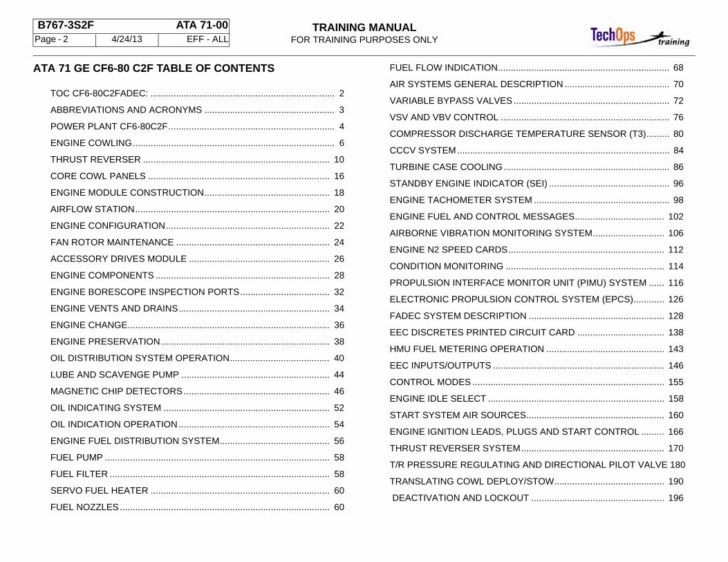
ATA 71 GE CF6-80 C2F TABLE OF CONTENTS
TOC CF6-80C2FADEC: ........................................................................ 2
ABBREVIATIONS AND ACRONYMS ................................................... 3
POWER PLANT CF6-80C2F................................................................. 4
ENGINE COWLING............................................................................... 6
THRUST REVERSER ......................................................................... 10
CORE COWL PANELS ....................................................................... 16
ENGINE MODULE CONSTRUCTION................................................. 18
AIRFLOW STATION............................................................................ 20
ENGINE CONFIGURATION................................................................ 22
FAN ROTOR MAINTENANCE ............................................................ 24
ACCESSORY DRIVES MODULE ....................................................... 26
ENGINE COMPONENTS .................................................................... 28
ENGINE BORESCOPE INSPECTION PORTS................................... 32
ENGINE VENTS AND DRAINS........................................................... 34
ENGINE CHANGE............................................................................... 36
ENGINE PRESERVATION.................................................................. 38
OIL DISTRIBUTION SYSTEM OPERATION....................................... 40
LUBE AND SCAVENGE PUMP .......................................................... 44
MAGNETIC CHIP DETECTORS ......................................................... 46
OIL INDICATING SYSTEM ................................................................. 52
OIL INDICATION OPERATION........................................................... 54
ENGINE FUEL DISTRIBUTION SYSTEM........................................... 56
FUEL PUMP ........................................................................................ 58
FUEL FILTER ...................................................................................... 58
SERVO FUEL HEATER ...................................................................... 60
FUEL NOZZLES.................................................................................. 60
FUEL FLOW INDICATION................................................................... 68
AIR SYSTEMS GENERAL DESCRIPTION ......................................... 70
VARIABLE BYPASS VALVES............................................................. 72
VSV AND VBV CONTROL .................................................................. 76
COMPRESSOR DISCHARGE TEMPERATURE SENSOR (T3)......... 80
CCCV SYSTEM................................................................................... 84
TURBINE CASE COOLING................................................................. 86
STANDBY ENGINE INDICATOR (SEI) ............................................... 96
ENGINE TACHOMETER SYSTEM ..................................................... 98
ENGINE FUEL AND CONTROL MESSAGES................................... 102
AIRBORNE VIBRATION MONITORING SYSTEM............................ 106
ENGINE N2 SPEED CARDS............................................................. 112
CONDITION MONITORING .............................................................. 114
PROPULSION INTERFACE MONITOR UNIT (PIMU) SYSTEM ...... 116
ELECTRONIC PROPULSION CONTROL SYSTEM (EPCS)............ 126
FADEC SYSTEM DESCRIPTION ..................................................... 128
EEC DISCRETES PRINTED CIRCUIT CARD .................................. 138
HMU FUEL METERING OPERATION .............................................. 143
EEC INPUTS/OUTPUTS ................................................................... 146
CONTROL MODES ........................................................................... 155
ENGINE IDLE SELECT ..................................................................... 158
START SYSTEM AIR SOURCES...................................................... 160
ENGINE IGNITION LEADS, PLUGS AND START CONTROL ......... 166
THRUST REVERSER SYSTEM........................................................ 170
T/R PRESSURE REGULATING AND DIRECTIONAL PILOT VALVE 180
TRANSLATING COWL DEPLOY/STOW........................................... 190
DEACTIVATION AND LOCKOUT .................................................... 196
TRAINING MANUALFOR TRAINING PURPOSES ONLY
B767-3S2F ATA 71-00 Page - 3 4/24/13 EFF - ALL
ABBREVIATIONS AND ACRONYMS
ACC - Active Clearance Control
ACTR- Actuator
AVM - Airborne Vibration Monitoring
CCCV - Core Compartment Cooling Valve
CTRL- Control
EEC - Electronic Engine Control
FADEC - Full Authority Digital Engine Control
GE - General Electric
gnd - ground
hdlg - handling
HMU - Hydro-mechanical Unit
HP - High Pressure
IDG - Integrated Drive Generator
LP - Low Pressure
PIMU - Propulsion Interface Monitoring Unit
PRSOV - Pressure Regulating and Shutoff Valve
TAI - Thermal Anti-Ice
TIP - Training Information Point
T/R - Thrust Reverser
T12 - Temperature at Station 1.2
svc - Service
VBV - Variable By-pass Valves
VSV - Variable Stator Vanes
N1 - Low Pressure Compressor Speed
N2 - High Pressure Compressor Speed
TRAINING MANUALFOR TRAINING PURPOSES ONLY
B767-3S2F ATA 71-00 Page - 4 4/24/13 EFF - ALL
GENERAL - POWER PLANT CF6-80C2F
Purpose
The two strut mounted engines provide the airplane with thrust, electrical power, pneumatic power, and hydraulic power.
General Description
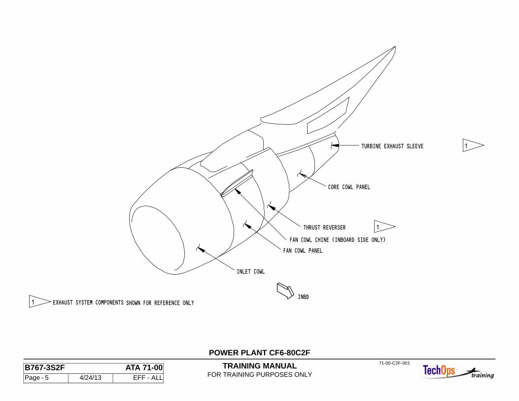
The power plant system is supported by the airplane strut. This includes the engine, cowling, exhaust, mount and drain components. The General Electric CF6-80C2F engines are a high bypass ratio (see engine specifications), dual rotor, turbofan engine.
Engine cowling consists of the inlet cowl, fan cowl and core cowl. The exhaust system discharges fan and turbine air through separate paths to atmosphere. Fan exhaust is directed through a pneumatic thrust reverser. Turbine exhaust passes through the exhaust sleeve. The forward and aft engine mounts carry thrust, vertical, side and torque loads.
Specifications CF6-80C2F
• Rated Thrust Classification 60,000 Pounds • Flat Rated Temperature 86F • Bypass Ratio 5.15 to 1 • Compressor Pressure Ratio 29.9 to 1 • EGT Redline (Max) 960C • N1 Redline (Max) 117.5% • N2 Redline (Max) 112.5% • Weight 9485 lbs
TRAINING MANUALFOR TRAINING PURPOSES ONLY
B767-3S2F ATA 71-00 Page - 5 4/24/13 EFF - ALL
TURBINE EXHAUST SLEEVE
INLET COWL
INBD
THRUST REVERSER
FAN COWL PANEL
CORE COWL PANEL
FAN COWL CHINE (INBOARD SIDE ONLY)
1
1
1 EXHAUST SYSTEM COMPONENTS SHOWN FOR REFERENCE ONLY
71-00-C2F-001
POWER PLANT CF6-80C2F
TRAINING MANUALFOR TRAINING PURPOSES ONLY
B767-3S2F ATA 71-00 Page - 6 4/24/13 EFF - ALL
GENERAL - ENGINE COWLING
Purpose
The cowling provides an aerodynamically smooth protective surface over the engine, engine-mounted components, and accessories. The cowling controls airflow around and through the engine, provides access to various areas of the engine case and fan case.
General Description
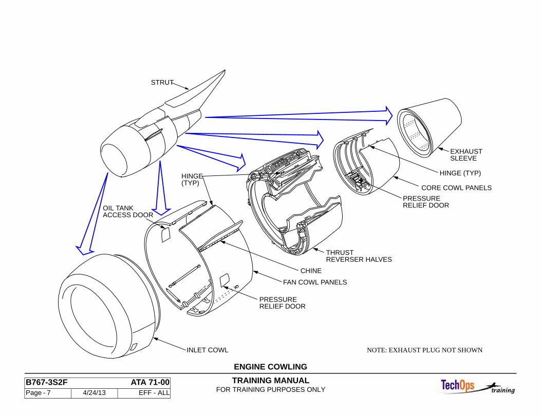
The cowling for each engine includes the inlet cowl, fan cowl, thrust reverser and core cowl. Access doors and openings are provided on the cowling to facilitate maintenance and servicing.
The turbine exhaust consists of hot, combusted gases exiting the low pressure turbine at high velocity. The major components of the turbine exhaust system are the exhaust sleeve and plug.
Fan cowls, thrust reversers and core cowls are mounted to the strut with hinges. Inlet cowl, exhaust sleeve and exhaust plug are bolted directly to the engine case.
General Operation
The engine cowling opening sequence is fan cowl, thrust reverser, core cowl, and closing sequence is in reverse order.
Together with associated exhaust systems, powerplant cowling performs several functions. It minimizes aerodynamic drag of the engine installation. It protects components within from hostile flight environments, provides sound suppression and directs airflow for proper engine operation. Also powerplant cowling provides for fire and over-pressure protection.
Inlet Cowl
Constructed of aluminum structure, with honeycomb core acoustical lining, and kevlar/graphite external panels. Approximately 106 inches outside diameter, 55 inches long and weighs 564 lbs.
Fan Cowls
Constructed of aluminum structure, with nomex honeycomb and kevlar/graphite external panels. The Fan Cowls are approximately 106 inches outside diameter, 53 inches long and weighs a total of 137 lbs. or 68.5 lbs each side.
Thrust Reverser Cowls
The fan thrust reverser cowls incorporate a self-contained hydraulic system to power open the reverser halves for engine access. They provide the forward thrust duct and also block and redirect this thrust forward to accomplish reverse thrust. The Fan Thrust Reverser Cowls are approximately 104 inches outside diameter, 63 inches long and weighs a total of 1538 lbs. or 769 lbs. each side.
Core Cowls
The Core Cowl panels are constructed of aluminum, titanium, and cres (corrosion resistant stainless steel). The Core Cowls are approximately 72 inches outside diameter, 59 inches long and weighs a total of 244 lbs. or 122 lbs. each side.
Exhaust Sleeve And Plug
Both the exhaust sleeve and plug are constructed of welded honeycomb.
TRAINING MANUALFOR TRAINING PURPOSES ONLY
B767-3S2F ATA 71-00 Page - 7 4/24/13 EFF - ALL
ENGINE COWLING
HINGE(TYP)
HINGE (TYP)
SLEEVEEXHAUST
INLET COWL
RELIEF DOORPRESSURE
CORE COWL PANELS
REVERSER HALVESTHRUST
OIL TANKACCESS DOOR
FAN COWL PANELS
RELIEF DOORPRESSURE
STRUT
NOTE: EXHAUST PLUG NOT SHOWN
CHINE
TRAINING MANUALFOR TRAINING PURPOSES ONLY
B767-3S2F ATA 71-00 Page - 8 4/24/13 EFF - ALL
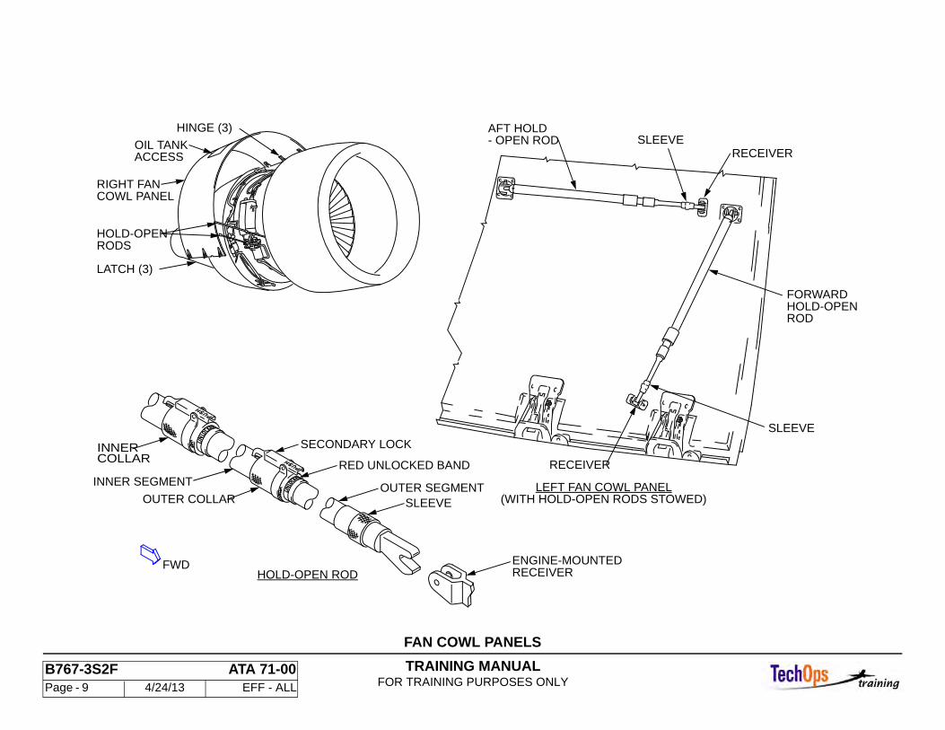
GENERAL - FAN COWL PANELS
Purpose
The left and right fan cowl panels protect the engine fan case.
Access
The fan cowl panels are hinged to the strut and fair with the inlet cowl and thrust reverser. Panels are latched together at the bottom centerline with three flush mounted tension latches. The fan cowl panels open to provide access to components on the engine fan case.
Characteristics
Each fan cowl overlaps the corresponding thrust reverser half. A pressure relief door, located midway up the left cowl, opens to relieve excessive fan cowl compartment pressures. The right fan cowl contains an access door to service the engine oil tank without opening the cowl. Two hold-open rods are installed on each fan cowl panel to support the cowl in the open position. The extended hold-open rods engage brackets on the fan case to hold the fan cowl open to positions of 40 or 55 degrees from the bottom centerline. The free ends of the rods are stowed in receivers on the cowl when not in use.
Opening Fan Cowl Panels
Release fan cowl latches and engage hold-open rods. Engage forward hold-open rod first, then engage aft hold-open rod.
WARNING: ADEQUATE SUPPORT OF FAN COWL PANEL MUST BE MAINTAINED WHILE ENGAGING HOLD-OPEN RODS TO PREVENT INJURY TO PERSONNEL AND/OR ENGINE COMPONENTS.
Retract sleeve at receiver end of hold-open rod to disengage rod from receiver. Fully extend rod to locked position. Check that red UNLOCKED indicator band is not visible.
WARNING: ENSURE THAT HOLD-OPEN ROD IS FULLY EXTENDED AND LOCKED TO PREVENT ACCIDENTAL CLOSING OF
COWL PANEL. PERSONNEL STRUCK BY FALLING COWL PANEL COULD BE SERIOUSLY INJURED. ROD IS NOT LOCKED IF RED BAND WITH THE WORD UNLOCKED IS VISIBLE. IF RED BAND IS VISIBLE, ROD WILL RETRACT UNDER LOAD.
With the sleeve retracted, engage hold-open rod onto engine mounted bracket and release sleeve. Brackets are mounted on engine flanges.
Closing Fan Cowl Panels
The corresponding thrust reverser half must be closed before closing the fan cowl panel. Disengage aft hold-open rod first, then disengage forward hold-open rod. Retract sleeve at receiver end of hold-open rod and disengage rod from engine mounted bracket. Rotate and slide collar in direction indicated to unlock hold-open rod from its extended position.
UNLOCKED indication should be visible. Retract hold-open rod and engage into fan cowl panel receiver.
CAUTION: DO NOT ALLOW FAN COWL PANEL TO SLAM CLOSED. DAMAGE TO FAN COWL PANEL AND/OR ENGINE COMPONENTS MAY RESULT.
Push fan cowl panels together and engage latches.
TRAINING MANUALFOR TRAINING PURPOSES ONLY
B767-3S2F ATA 71-00 Page - 9 4/24/13 EFF - ALL
FAN COWL PANELS
SLEEVE
HOLD-OPENROD
FORWARD
HINGE (3)
HOLD-OPENRODS
LATCH (3)
RIGHT FANCOWL PANEL
ENGINE-MOUNTEDRECEIVER
INNER SEGMENT
SLEEVEOUTER SEGMENT
INNER
OUTER COLLAR
RED UNLOCKED BAND
- OPEN RODRECEIVER
RECEIVER
SECONDARY LOCK
SLEEVE
HOLD-OPEN ROD
(WITH HOLD-OPEN RODS STOWED)LEFT FAN COWL PANEL
ACCESSOIL TANK
AFT HOLD
COLLAR
FWD
TRAINING MANUALFOR TRAINING PURPOSES ONLY
B767-3S2F ATA 71-00 Page - 10 4/24/13 EFF - ALL
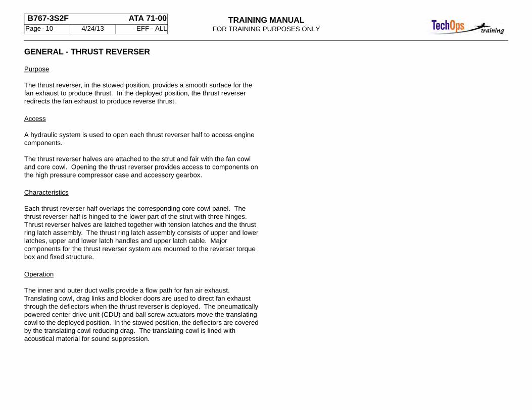
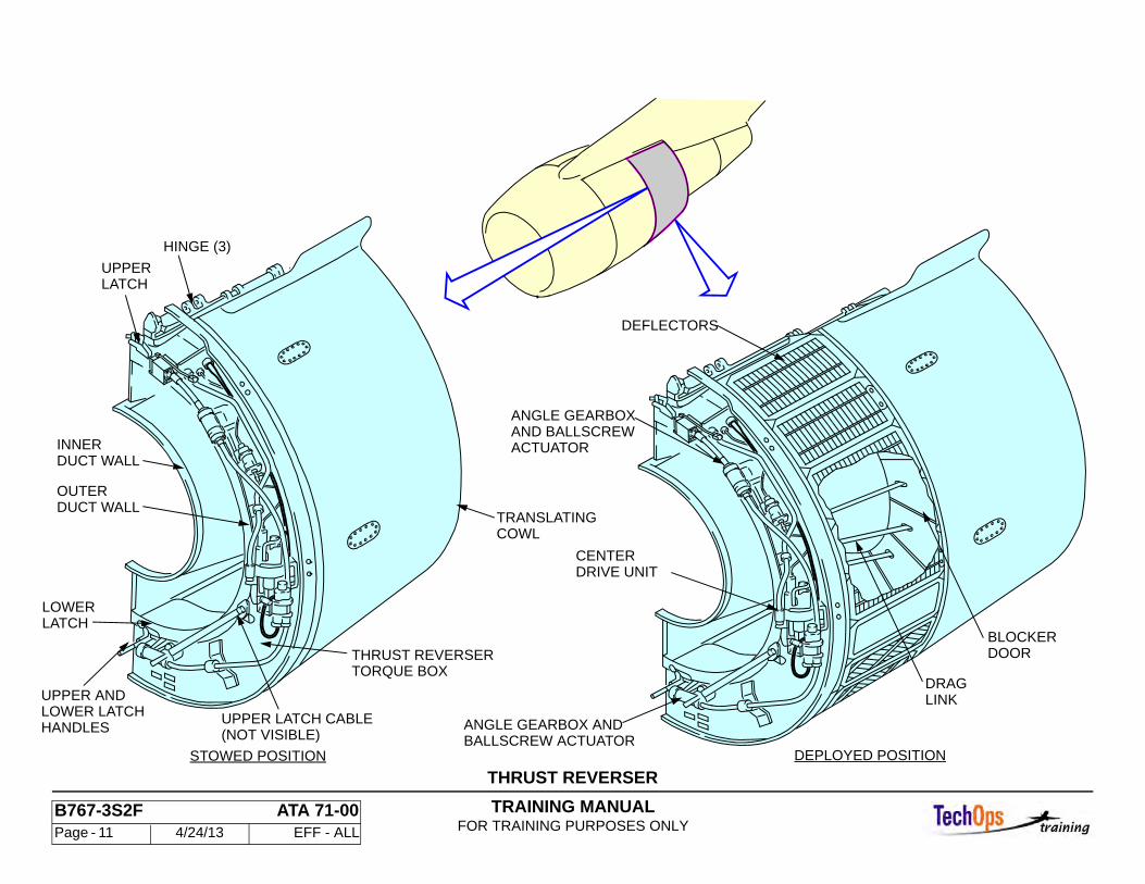
GENERAL - THRUST REVERSER
Purpose
The thrust reverser, in the stowed position, provides a smooth surface for the fan exhaust to produce thrust. In the deployed position, the thrust reverser redirects the fan exhaust to produce reverse thrust.
Access
A hydraulic system is used to open each thrust reverser half to access engine components.
The thrust reverser halves are attached to the strut and fair with the fan cowl and core cowl. Opening the thrust reverser provides access to components on the high pressure compressor case and accessory gearbox.
Characteristics
Each thrust reverser half overlaps the corresponding core cowl panel. The thrust reverser half is hinged to the lower part of the strut with three hinges. Thrust reverser halves are latched together with tension latches and the thrust ring latch assembly. The thrust ring latch assembly consists of upper and lower latches, upper and lower latch handles and upper latch cable. Major components for the thrust reverser system are mounted to the reverser torque box and fixed structure.
Operation
The inner and outer duct walls provide a flow path for fan air exhaust. Translating cowl, drag links and blocker doors are used to direct fan exhaust through the deflectors when the thrust reverser is deployed. The pneumatically powered center drive unit (CDU) and ball screw actuators move the translating cowl to the deployed position. In the stowed position, the deflectors are covered by the translating cowl reducing drag. The translating cowl is lined with acoustical material for sound suppression.
TRAINING MANUALFOR TRAINING PURPOSES ONLY
B767-3S2F ATA 71-00 Page - 11 4/24/13 EFF - ALL
THRUST REVERSER
BALLSCREW ACTUATORANGLE GEARBOX AND
DRIVE UNITCENTER
ACTUATORAND BALLSCREWANGLE GEARBOX
DOORBLOCKER
LINKDRAG
LATCHUPPER
DUCT WALLINNER
DUCT WALLOUTER
LATCHLOWER
HANDLESLOWER LATCHUPPER AND
COWLTRANSLATING
TORQUE BOXTHRUST REVERSER
(NOT VISIBLE)UPPER LATCH CABLE
DEFLECTORS
DEPLOYED POSITIONSTOWED POSITION
HINGE (3)
TRAINING MANUALFOR TRAINING PURPOSES ONLY
B767-3S2F ATA 71-00 Page - 12 4/24/13 EFF - ALL
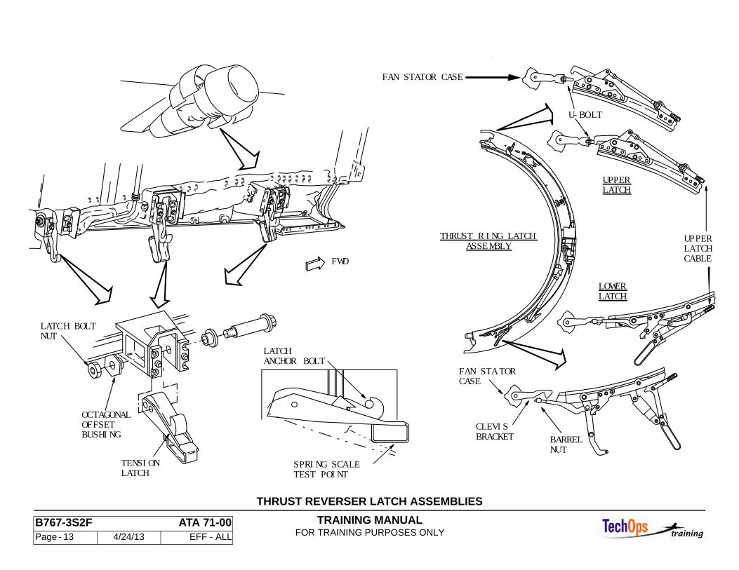
GENERAL - THRUST REVERSER LATCH ASSEMBLIES
Purpose
The thrust ring latch assembly secures the outer leading edge of the thrust reverser halves to the aft flange of the fan frame and case. It transmits reverser loads into the engine fan frame instead of the strut hinges.
Location and Access
This assembly is mounted around the leading edge of each thrust reverser half. Access is gained by opening the appropriate fan cowl panel.
Characteristics
The upper latch of the mounting ring is a hook that slips into a "U" bolt, mounted to a bracket, on top of the fan stator case. Upper latching force is controlled by the adjustable "U" bolt. The bottom latch is a barrel nut that fits into a "claw" type clevis bracket mounted at the bottom of the fan case. The barrel nut is adjustable to control lower latching force. Upper and lower latch handles are used to open/close upper and lower latches. The upper latch cable is adjustable. The thrust ring latch assembly may be removed if the thrust reverser half is replaced.
Operations and Limitations
Opening the thrust ring latch assembly requires pulling lower latch handle outward until latch pin bottoms in slot. Rotate upper latch handle outward disengaging latch pin from slot. The upper latch is now disengaged from the "U" bolt. Rotate lower latch handle outward disengaging barrel nut from clevis bracket. Closing the thrust ring latch assembly requires engaging barrel nut with clevis and rotate lower latch handle inward. Rotate upper latch handle inward engaging latch pin in slot. Upper latch should engage "U" bolt.
CAUTION: DO A VISUAL CHECK THAT THE LATCH RING HOOK HAS ENGAGED THE "U" BOLT WHEN CLOSING. ALSO, WHEN OPENING THE COWLING ENSURE THE LATCH HOOK IS CLEAR OF THE RING HOOK. FAILURE TO COMPLY WITH THIS COULD CAUSE DAMAGE TO THE COWLING AS WELL AS THE ENGINE PYLON.
General
The thrust reverser halves are latched together by three tension latches along the bottom split-line. The latches are mounted within the area covered by the access and blow-out doors on the bottom of the thrust reverser. The forward blow-out door must be opened first and closed last. Latch hooks are on the left half and fit over latch pins on the right half. Latch tension is adjustable.
Adjustment
The fan cowl panels must be open. The access and blow-out doors must be open. Unlatch all three tension latches in order, starting with the aft latch, working forward. Check the tension latches for damage.
The tension latch handle closing force is measured with a spring scale. Adjust tension latches from forward to rear. Adjust the closing force by loosening the latch bolt nut and rotating an octagonal offset bushing.
TRAINING MANUALFOR TRAINING PURPOSES ONLY
B767-3S2F ATA 71-00 Page - 13 4/24/13 EFF - ALL
THRUST REVERSER LATCH ASSEMBLIES
NUTLATCH BOLT
OCTAGONALOFFSETBUSHING
TENSIONLATCH TEST POINT
SPRING SCALE
LATCHANCHOR BOLT
FWD
U-BOLT
ASSEMBLY
FAN STA TORCASE
LOWER
UPPERLATCH
THRUST R ING LATCH
CLEVISBARRELNUT
BRACKET
UPPERLATCHCABLE
LATCH
FAN STATOR CASE
TRAINING MANUALFOR TRAINING PURPOSES ONLY
B767-3S2F ATA 71-00 Page - 14 4/24/13 EFF - ALL
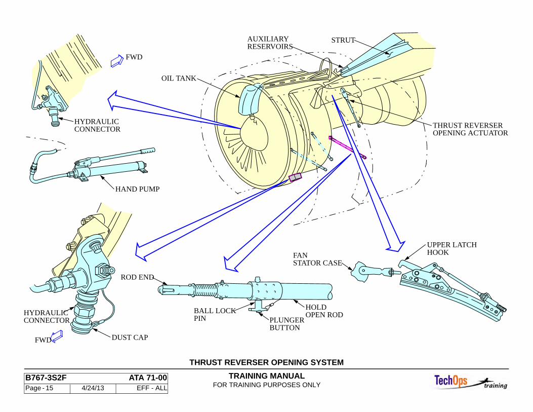
GENERAL - THRUST REVERSER OPENING SYSTEM
General
The thrust reverser cowl opening is done with a hydraulic power opening system. A hand pump is required for opening/closing the thrust reverser.
A hand pump can be connected to a quick disconnect to manually open the thrust reverser.
Thrust Reverser Opening Actuator
The thrust reverser opening actuator is driven by hydraulic pressure to open each thrust reverser half.
Each thrust reverser opening actuator is mounted to a bracket on each side of the airplane strut. The thrust reverser opening relief valve is mounted to the multiple connector. A flexible hose is connected from the strut T-Fitting to the thrust reverser opening actuator inlet fitting.
The thrust reverser opening actuator inlet fitting incorporates a restrictor as a safety device limiting the rate of closure. In the event of a hydraulic line rupture or rapid closure, the restrictor provides a minimum 15 second closing cycle. A 25 micron filter at the input fitting protects the restrictor and actuator assembly from fluid contamination.
The thrust reverser opening relief valve is for system high pressure relief and is set 4350 - 4500 psig.
Thrust Reverser Hold Open Rods
Each thrust reverser half has one hold open rod. The rod pivots from a torque box mount under the center drive unit and is held in stowed position with a quick release clamp.
The hold open rod consists of an inner rod telescoped inside an outer tube. The hold open rod is held in the telescoped position by a ball lockpin which passes through both inner rod and outer tube through either of two holes. The hold open rod engages a single bracket on the engine fan case and holds the reverser half open to the 34 or 45 degree position depending on which hole is engaged.
TRAINING MANUALFOR TRAINING PURPOSES ONLY
B767-3S2F ATA 71-00 Page - 15 4/24/13 EFF - ALL
THRUST REVERSER OPENING SYSTEM
OPENING ACTUATORTHRUST REVERSER
STRUTRESERVOIRSAUXILIARY
OIL TANK
OPEN RODHOLD
PINBALL LOCK
ROD END
BUTTONPLUNGERCONNECTOR
HYDRAULIC
DUST CAP
HAND PUMP
CONNECTORHYDRAULIC
HOOKUPPER LATCH
STATOR CASEFAN
FWD
FWD
TRAINING MANUALFOR TRAINING PURPOSES ONLY
B767-3S2F ATA 71-00 Page - 16 4/24/13 EFF - ALL
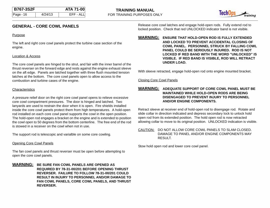
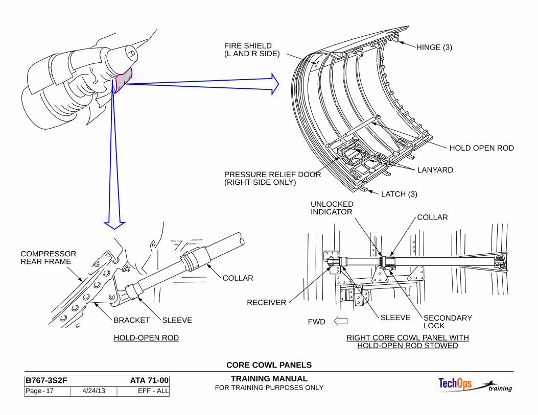
GENERAL - CORE COWL PANELS
Purpose
The left and right core cowl panels protect the turbine case section of the engine.
Location & Access
The core cowl panels are hinged to the strut, and fair with the inner barrel of the thrust reverser on the forward edge and rests against the engine exhaust sleeve on the aft edge. Panels are latched together with three flush mounted tension latches at the bottom. The core cowl panels open to allow access to the combustion and turbine cases of the engine.
Characteristics
A pressure relief door on the right core cowl panel opens to relieve excessive core cowl compartment pressures. The door is hinged and latched. Two lanyards are used to restrain the door when it is open. Fire shields installed inside the core cowl panels protect them from high temperatures. A hold-open rod installed on each core cowl panel supports the cowl in the open position. The hold-open rod engages a bracket on the engine and is extended to position the cowl open to 50 degrees from the bottom centerline. The free end of the rod is stowed in a receiver on the cowl when not in use.
The support rod is telescopic and varialble on some core cowling.
Opening Core Cowl Panels
The fan cowl panels and thrust reverser must be open before attempting to open the core cowl panels.
WARNING: BE SURE FAN COWL PANELS ARE OPENED AS REQUIRED BY 78-31-00/201 BEFORE OPENING THRUST REVERSER. FAILURE TO FOLLOW 78-31-00/201 COULD RESULT IN INJURY TO PERSONNEL AND/OR DAMAGE TO FAN COWL PANELS, CORE COWL PANELS, AND THRUST REVERSER.
Release core cowl latches and engage hold-open rods. Fully extend rod to locked position. Check that red UNLOCKED indicator band is not visible.
WARNING: ENSURE THAT HOLD-OPEN ROD IS FULLY EXTENDED AND LOCKED TO PREVENT ACCIDENTAL CLOSING OF COWL PANEL. PERSONNEL STRUCK BY FALLING COWL PANEL COULD BE SERIOUSLY INJURED. ROD IS NOT LOCKED IF RED BAND WITH THE WORD "UNLOCKED" IS VISIBLE. IF RED BAND IS VISIBLE, ROD WILL RETRACT UNDER LOAD.
With sleeve retracted, engage hold-open rod onto engine mounted bracket.
Closing Core Cowl Panels
WARNING: ADEQUATE SUPPORT OF CORE COWL PANEL MUST BE MAINTAINED WHILE HOLD-OPEN RODS ARE BEING DISENGAGED TO PREVENT INJURY TO PERSONNEL AND/OR ENGINE COMPONENTS.
Retract sleeve at receiver end of hold-open rod to disengage rod. Rotate and slide collar in direction indicated and depress secondary lock to unlock hold open rod from its extended position. The hold open rod is now retracted allowing collar to move to its original position. UNLOCKED indication is visible.
CAUTION: DO NOT ALLOW CORE COWL PANELS TO SLAM CLOSED. DAMAGE TO PANEL AND/OR ENGINE COMPONENTS MAY RESULT.
Stow hold open rod and lower core cowl panel.
TRAINING MANUALFOR TRAINING PURPOSES ONLY
B767-3S2F ATA 71-00 Page - 17 4/24/13 EFF - ALL
CORE COWL PANELS
HOLD OPEN ROD
REAR FRAMECOMPRESSOR
LANYARD
UNLOCKEDINDICATOR
SLEEVE
COLLAR
RECEIVER
SECONDARYLOCK
RIGHT CORE COWL PANEL WITH
FIRE SHIELD
LATCH (3)
HINGE (3)(L AND R SIDE)
BRACKET SLEEVE
COLLAR
HOLD-OPEN ROD
(RIGHT SIDE ONLY)PRESSURE RELIEF DOOR
HOLD-OPEN ROD STOWED
FWD
TRAINING MANUALFOR TRAINING PURPOSES ONLY
B767-3S2F ATA 71-00 Page - 18 4/24/13 EFF - ALL
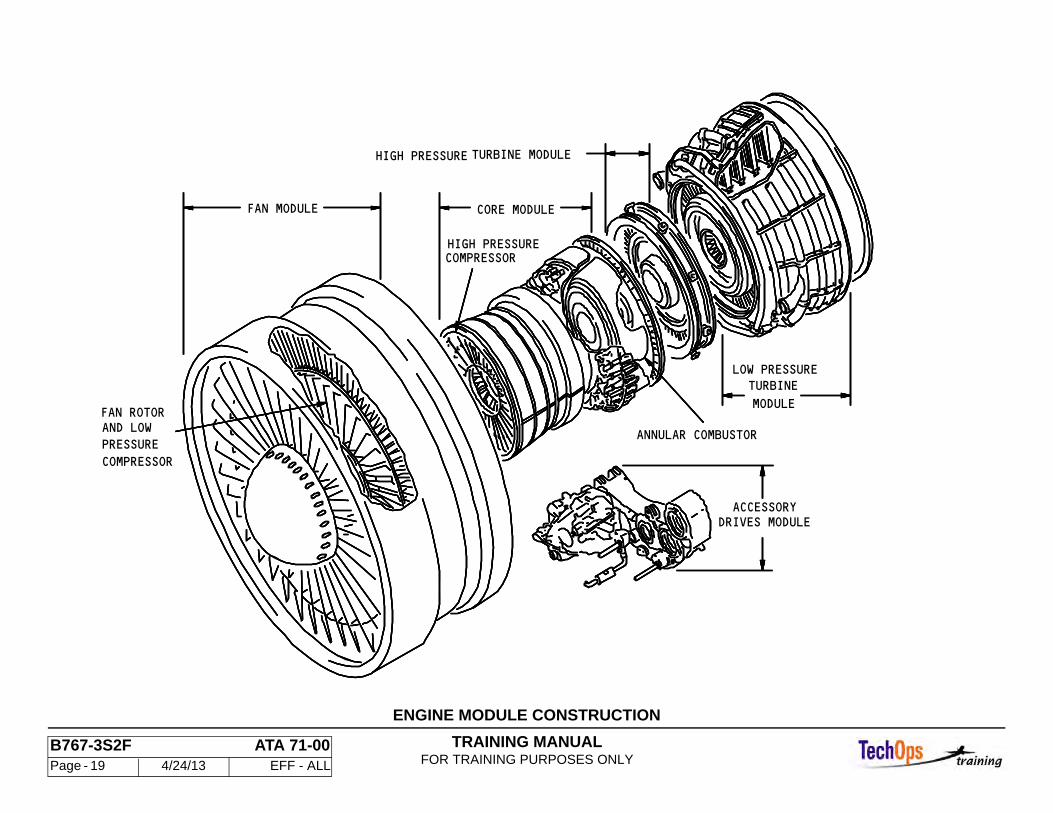
GENERAL - ENGINE MODULE CONSTRUCTION
System Description
The CF6-80C2F is a dual spool, axial flow, high bypass ratio turbofan power plant. It has an integrated fan rotor and low pressure compressor (also referred to as a "booster compressor" and a 14 stage high pressure compressor (HPC). The combustor is annular type. A 2-stage high pressure turbine (HPT) drives the high pressure compressor, while a 5-stage low pressure turbine (LPT) drives the fan and low pressure compressor.
Five modules make up the engine. Each module may be replaced as an assembly without affecting engine performance or integrity. The five modules are:
• Fan module • Core module • High pressure turbine module • Low pressure turbine module • Accessory drives module
TRAINING MANUALFOR TRAINING PURPOSES ONLY
B767-3S2F ATA 71-00 Page - 19 4/24/13 EFF - ALL
COMPRESSOR
PRESSUREAND LOWFAN ROTOR
ANNULAR COMBUSTOR
HIGH PRESSURE TURBINE MODULE
COMPRESSORHIGH PRESSURE
DRIVES MODULE
LOW PRESSURE
CORE MODULEFAN MODULE
MODULE
TURBINE
ACCESSORY
ENGINE MODULE CONSTRUCTION
TRAINING MANUALFOR TRAINING PURPOSES ONLY
B767-3S2F ATA 71-00 Page - 20 4/24/13 EFF - ALL
AERODYNAMIC STATIONS
Identification
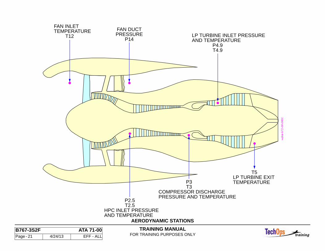
Gas turbine engine manufacturers adhere to Aerospace Recommended Practice (ARP) 755A when assigning aerodynamic station numbers. This standard was developed by the Society Of Automotive Engineers, Inc. and provides performance station identification and nomenclature systems for gas turbine engines. These identifications are referenced by number and alpha characters and relate to both primary and secondary airflow gas paths.
The primary airflow path is identified with numbers 0 through 9 and secondary airflow paths are identified with numbers 10 through 19. Any points of measurement between whole numbers is identified in decimal equivalents.
The alpha prefix character(s) are used to clarify whether air temperature or air pressure are being measured. They also indicate the manner in which the temperature or pressure is being measured. Of the many characters available those used on the GE engines are:
T = TemperatureP = PressureS = Static
Engine Instrument Sensor/Station Relationships
Temperature and pressure sensors are labeled with a T or a P, and a station number which indicates the location of the sensor in the airflow. The CF6-80C2 sensors (not shown) are:
• T12: (Electrical) inlet temperature (2) • P14: Fan duct pressure (Condition Monitoring System) • P2.5: HPC inlet pressure • T2.5: HPC inlet temperature (Condition Monitoring System) • P3: Compressor discharge pressure • T3: Compressor discharge temperature • P4.9: LP turbine inlet pressure (Condition Monitoring System) • T4.9: LP turbine inlet temperature (EGT) • T5: LP turbine exit temperature (Condition Monitoring System)
TRAINING MANUALFOR TRAINING PURPOSES ONLY
B767-3S2F ATA 71-00 Page - 21 4/24/13 EFF - ALL
AERODYNAMIC STATIONS
T12TEMPERATUREFAN INLET
P14PRESSUREFAN DUCT
T4.9P4.9
AND TEMPERATURELP TURBINE INLET PRESSURE
AND TEMPERATUREHPC INLET PRESSURE
T2.5P2.5
PRESSURE AND TEMPERATURECOMPRESSOR DISCHARGE
T3P3 TEMPERATURE
LP TURBINE EXITT5
wdm
t-h7
2-00
-000
1
TRAINING MANUALFOR TRAINING PURPOSES ONLY
B767-3S2F ATA 71-00 Page - 22 4/24/13 EFF - ALL
GENERAL - ENGINE CONFIGURATION
General Configuration
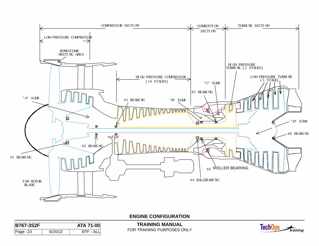
The basic engine configuration for the CF6-80C engine consists of four Sump location:
• Sump A • Sump B • Sump C • Sump D
Sump A has the #1, 2, and 3 bearings. The B sump has #4, Roller and Ball type bearings. The C sump contains the #5 bearing and is located just forward of the HPT inlet. The D sump is the furthest aft on the engine at the LPT outlet..
The LPC module on the CF6-80C engine has four stages of compression and a single stage fan section. This is also referred to as the booster section. The HPC area consists of 14 stages of compression and is located in the main core of the engine forward of the combustion case. A single annular combustor is used on the engine for fuel introduction and combustion. The HPT consists a two stage turbine and is used to drive the 14 stage HPC. The LPT has a five stage turbine and is used to drive the booster section of the engine.
TRAINING MANUALFOR TRAINING PURPOSES ONLY
B767-3S2F ATA 71-00 Page - 23 4/24/13 EFF - ALL
ENGINE CONFIGURATION
L
FAN ROTORBLADE
COMPRESSOR SECTION COMBUSTIONSECTION
TURBINE SECTION
HIGH PRESSURE COMPRESSOR(14 STAGES)
LOW PRESSURE COMPRESSOR
HIGH PRESSURETURBINE (2 STAGES)
LOW PRESSURE TURBINE
"D" SUMP
"B" SUMP"A" SUMP #3 BEARING
#1 BEARING
#2 BEARING
#5 BEARING
#4 ROLLERBEARING
#4 BALLBEARING
HONEYCOMBNESTING AREA
(5 STAGE)
#6 BEARING
"C" SUMP
ROLLER BEARING
TRAINING MANUALFOR TRAINING PURPOSES ONLY
B767-3S2F ATA 71-00 Page - 24 4/24/13 EFF - ALL
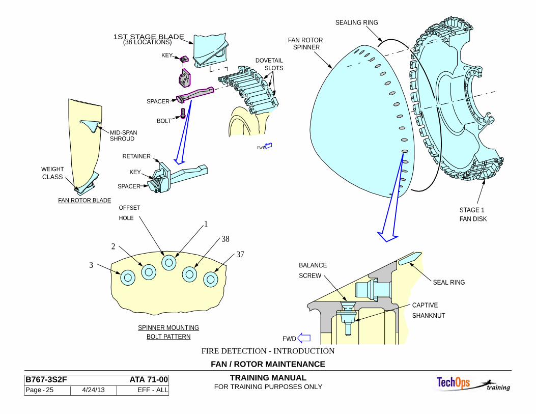
GENERAL - FAN ROTOR MAINTENANCE
Fan Rotor Spinner
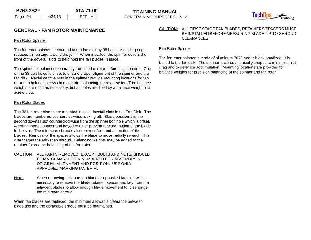
The fan rotor spinner is mounted to the fan disk by 38 bolts. A sealing ring reduces air leakage around the joint. When installed, the spinner covers the front of the dovetail slots to help hold the fan blades in place.
The spinner is balanced separately from the fan rotor before it is mounted. One of the 38 bolt holes is offset to ensure proper alignment of the spinner and the fan disk. Radial captive nuts in the spinner provide mounting locations for fan rotor trim balance screws to make trim balancing the rotor easier. Trim balance weights are used as necessary, but all holes are filled by a balance weight or a screw plug.
Fan Rotor Blades
The 38 fan rotor blades are mounted in axial dovetail slots in the Fan Disk. The blades are numbered counterclockwise looking aft. Blade position 1 is the second dovetail slot counterclockwise from the spinner bolt hole which is offset. A spring-loaded spacer and keyed retainer prevent forward motion of the blade in the slot. The mid-span shrouds also prevent fore and aft motion of the blades. Removal of the spacer allows the blade to move radially inward. This disengages the mid-span shroud. Balancing weights may be added to the retainer for coarse balancing of the fan rotor.
CAUTION: ALL PARTS REMOVED, EXCEPT BOLTS AND NUTS, SHOULD BE MATCHMARKED OR NUMBERED FOR ASSEMBLY IN ORIGINAL ALIGNMENT AND POSITION. USE ONLY APPROVED MARKING MATERIAL.
Note: When removing only one fan blade or opposite blades, it will be necessary to remove the blade retainer, spacer and key from the adjacent blades to allow enough blade movement to disengage the mid-span shroud.
When fan blades are replaced, the minimum allowable clearance between blade tips and the abradable shroud must be maintained.
CAUTION: ALL FIRST STAGE FAN BLADES, RETAINERS/SPACERS MUST BE INSTALLED BEFORE MEASURING BLADE TIP-TO-SHROUD CLEARANCES.
Fan Rotor Spinner
The fan rotor spinner is made of aluminum 7075 and is black anodized. It is bolted to the fan disk. The spinner is aerodynamically shaped to minimize inlet drag and to deter ice accumulation. Mounting locations are provided for balance weights for precision balancing of the spinner and fan rotor.
TRAINING MANUALFOR TRAINING PURPOSES ONLY
B767-3S2F ATA 71-00 Page - 25 4/24/13 EFF - ALL
FAN / ROTOR MAINTENANCE
FIRE DETECTION - INTRODUCTION
FAN ROTOR BLADE
SHROUDMID-SPAN
(38 LOCATIONS)1ST STAGE BLADE
RETAINER
BOLT
KEY
SPACER
SLOTSDOVETAIL
SPACER
KEYWEIGHTCLASS
FWD
2
1
38
BOLT PATTERNSPINNER MOUNTING
HOLE
OFFSET
373
FAN DISKSTAGE 1
SPINNERFAN ROTOR
SEALING RING
FWD
CAPTIVE
SHANKNUT
SEAL RINGSCREW
BALANCE
TRAINING MANUALFOR TRAINING PURPOSES ONLY
B767-3S2F ATA 71-00 Page - 26 4/24/13 EFF - ALL
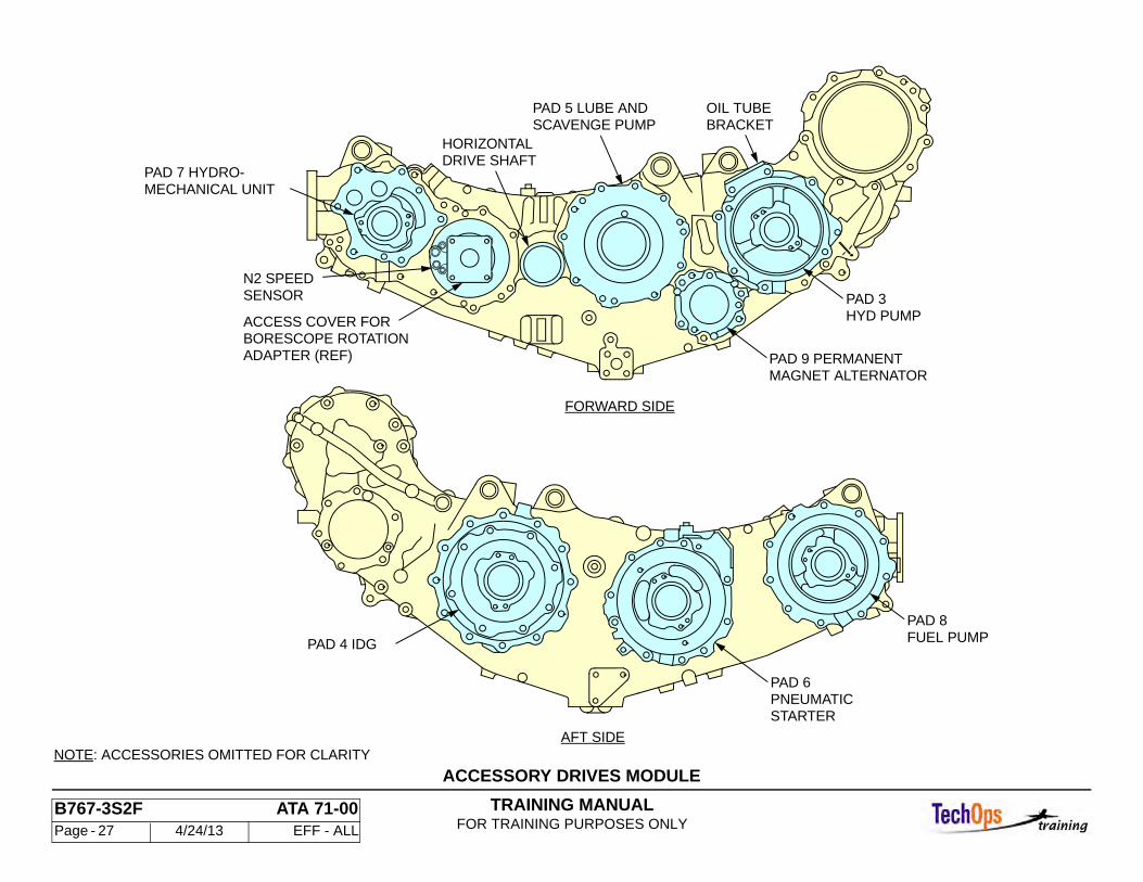
GENERAL - ACCESSORY DRIVE MODULES
General
Most of the gear driven engine accessories are mounted on, and driven by the accessory gearbox. Refer to the diagram for the pad locations for the following accessories:
Forward Side
• Main engine control (Fuel Control Unit) • Lube and scavenge pump assembly • EEC Control alternator • Hydraulic pump
Aft Side
• Integrated Drive Generator (IDG) • Pneumatic starter • Fuel pump
TRAINING MANUALFOR TRAINING PURPOSES ONLY
B767-3S2F ATA 71-00 Page - 27 4/24/13 EFF - ALL
ACCESSORY DRIVES MODULE
N2 SPEED
ADAPTER (REF)
ACCESS COVER FOR
NOTE: ACCESSORIES OMITTED FOR CLARITY
BRACKETOIL TUBE
DRIVE SHAFTHORIZONTAL
SCAVENGE PUMPPAD 5 LUBE AND
PAD 4 IDG FUEL PUMPPAD 8
STARTERPNEUMATICPAD 6
MAGNET ALTERNATORPAD 9 PERMANENT
HYD PUMPPAD 3
AFT SIDE
FORWARD SIDE
MECHANICAL UNITPAD 7 HYDRO-
BORESCOPE ROTATION
SENSOR
TRAINING MANUALFOR TRAINING PURPOSES ONLY
B767-3S2F ATA 71-00 Page - 28 4/24/13 EFF - ALL
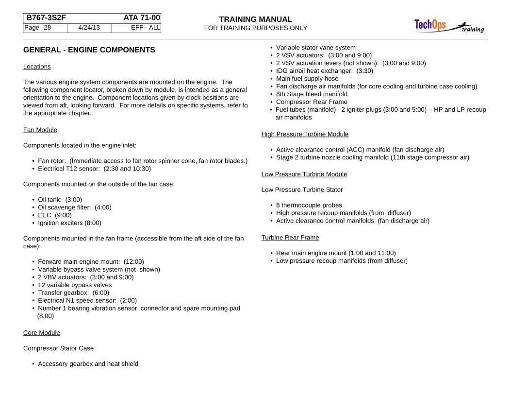
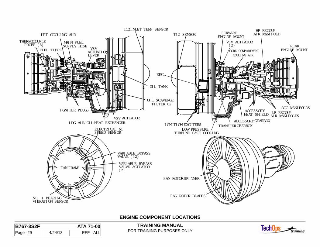
GENERAL - ENGINE COMPONENTS
Locations
The various engine system components are mounted on the engine. The following component locator, broken down by module, is intended as a general orientation to the engine. Component locations given by clock positions are viewed from aft, looking forward. For more details on specific systems, refer to the appropriate chapter.
Fan Module
Components located in the engine inlet:
• Fan rotor: (Immediate access to fan rotor spinner cone, fan rotor blades.) • Electrical T12 sensor: (2:30 and 10:30)
Components mounted on the outside of the fan case:
• Oil tank: (3:00) • Oil scavenge filter: (4:00) • EEC (9:00) • Ignition exciters (8:00)
Components mounted in the fan frame (accessible from the aft side of the fan case):
• Forward main engine mount: (12:00) • Variable bypass valve system (not shown) • 2 VBV actuators: (3:00 and 9:00) • 12 variable bypass valves • Transfer gearbox: (6:00) • Electrical N1 speed sensor: (2:00) • Number 1 bearing vibration sensor connector and spare mounting pad
(8:00)
Core Module
Compressor Stator Case
• Accessory gearbox and heat shield
• Variable stator vane system • 2 VSV actuators: (3:00 and 9:00) • 2 VSV actuation levers (not shown): (3:00 and 9:00) • IDG air/oil heat exchanger: (3:30) • Main fuel supply hose • Fan discharge air manifolds (for core cooling and turbine case cooling) • 8th Stage bleed manifold • Compressor Rear Frame • Fuel tubes (manifold) - 2 igniter plugs (3:00 and 5:00) - HP and LP recoup
air manifolds
High Pressure Turbine Module
• Active clearance control (ACC) manifold (fan discharge air) • Stage 2 turbine nozzle cooling manifold (11th stage compressor air)
Low Pressure Turbine Module
Low Pressure Turbine Stator
• 8 thermocouple probes • High pressure recoup manifolds (from diffuser) • Active clearance control manifolds (fan discharge air)
Turbine Rear Frame
• Rear main engine mount (1:00 and 11:00) • Low pressure recoup manifolds (from diffuser)
TRAINING MANUALFOR TRAINING PURPOSES ONLY
B767-3S2F ATA 71-00 Page - 29 4/24/13 EFF - ALL
SPINNERFAN ROTOR
(2)VSV ACTUATOR
(2)
VALVE (12)VARIABLE BYPASS
VALVE ACTUATORVARIABLE BYPASS
SPEED SENSORELECTRICAL N1
FRAMEFAN
FAN ROTOR BLADESVIBRATION SENSORNO. 1 BEARING
HEAT EXCHANGER
SUPPLY HOSEMAIN FUEL
FUEL TUBESPROBE (8)
ACTUATORVSV
FILTER C2OIL SCAVENGE
OIL TANK
IDG AIR/OIL
VSV
THERMOCOUPLE
LEVER
IGNITER PLUGS
T12INLET TEMP SENSOR
ACTUATION
T12 SENSOR
HEAT SHIELD
ENGINE MOUNT
ACCESSORY GEARBOXGEARBOXTRANSFER
ACC MANIFOLDS
AIR MANIFOLDSLP RECOUPACCESSORY
EXCITERSIGNITION
HP RECOUPAIR MANIFOLDENGINE MOUNT
FORWARD
REAR
EEC
HPT COOLING AIR
CORE COMPARTMENTCOOLING AIR
LOW PRESSURETURBINE CASE COOLING
ENGINE COMPONENT LOCATIONS
TRAINING MANUALFOR TRAINING PURPOSES ONLY
B767-3S2F ATA 71-00 Page - 30 4/24/13 EFF - ALL
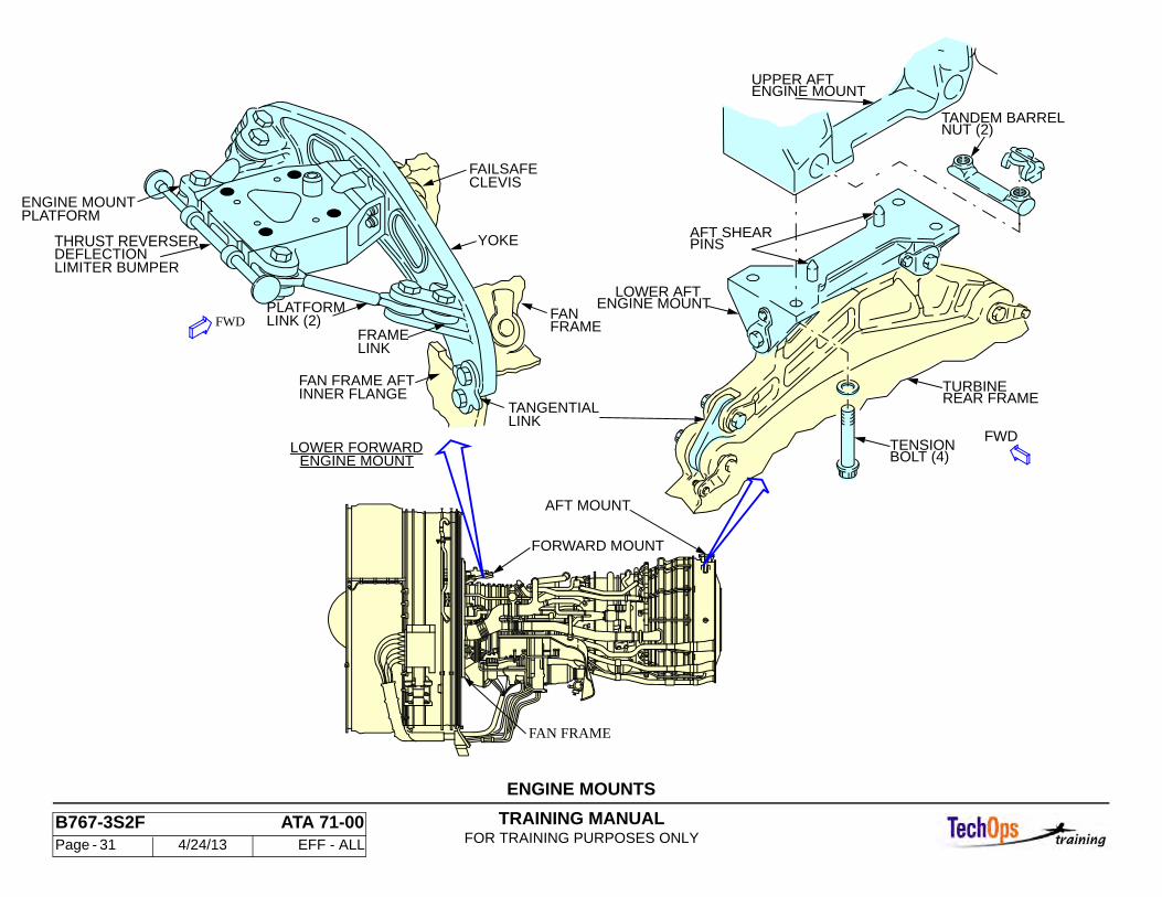
GENERAL - ENGINE MOUNTS
Purpose
The forward and aft engine mounts transfer engine thrust and absorb vertical and side loads. The mounts allow axial and radial growth due to thermal expansion.
General Component Locations
The forward mount is attached to the fan frame aft inner flange and the aft mount is attached to the turbine rear frame.
Inspection/check or removal/installation of either engine mount requires removal of the engine.
Characteristics
Forward Lower Engine Mount - This mount provides suspension of the engine at three points. The two thrust links are attached to the inner fan frame on either side of the mount assembly. The forward lower engine mount is attached to the strut by four tension bolts.
Aft Lower Engine Mount - The mount lower fitting suspends the engine at two points from a double flange on the turbine rear frame. The upper fitting is attached to the strut by four bolts and barrel nuts. One point incorporates a tangential link. The aft mount transfers side, vertical and torque loads.
TRAINING MANUALFOR TRAINING PURPOSES ONLY
B767-3S2F ATA 71-00 Page - 31 4/24/13 EFF - ALL
ENGINE MOUNTS
FAN FRAME
FORWARD MOUNT
LOWER FORWARD
INNER FLANGEFAN FRAME AFT
LIMITER BUMPER
THRUST REVERSERDEFLECTION
PLATFORMENGINE MOUNT
YOKE
FRAMEFAN
FAILSAFECLEVIS
LINK (2)PLATFORM
FRAME
LINKTANGENTIAL
LINK
ENGINE MOUNT
FWD
AFT MOUNT
TANDEM BARRELNUT (2)
UPPER AFT
LOWER AFT
BOLT (4)TENSION
REAR FRAMETURBINE
AFT SHEARPINS
ENGINE MOUNT
ENGINE MOUNT
FWD
TRAINING MANUALFOR TRAINING PURPOSES ONLY
B767-3S2F ATA 71-00 Page - 32 4/24/13 EFF - ALL
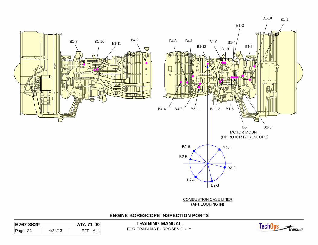
GENERAL - ENGINE BORESCOPE INSPECTION PORTS
General
Inspection of the internal parts of the engine is primarily done by means of the borescope. The engine has access for borescope inspection of each stage of the high pressure compressor, high pressure and low-pressure turbine inlets, and from ports at Stages 2 and 4 of the low pressure turbine. Additional borescope-access holes are provided in the compressor rear frame for the inspection of combustion liner and first stage turbine nozzle. A hand-operated or motor-driven system is available to facilitate borescope viewing of all high pressure rotor blades. This mounts to the accessory gearbox.
TRAINING MANUALFOR TRAINING PURPOSES ONLY
B767-3S2F ATA 71-00 Page - 33 4/24/13 EFF - ALL
ENGINE BORESCOPE INSPECTION PORTS
B1-7 B1-10 B1-11
B4-2
B1-1
B1-10
B4-4
B4-3 B4-1B1-13
B1-9
B1-8
B1-4
B1-3
B1-2
B3-2 B3-1 B1-12 B1-6
B1-5B5MOTOR MOUNT
B2-2
B2-3
B2-1
B2-4
B2-5
B2-6
(HP ROTOR BORESCOPE)
(AFT LOOKING IN)COMBUSTION CASE LINER
B4-2 B4-3 B4-1B1-13
B1-8B1-2
B1-10
TRAINING MANUALFOR TRAINING PURPOSES ONLY
B767-3S2F ATA 71-00 Page - 34 4/24/13 EFF - ALL
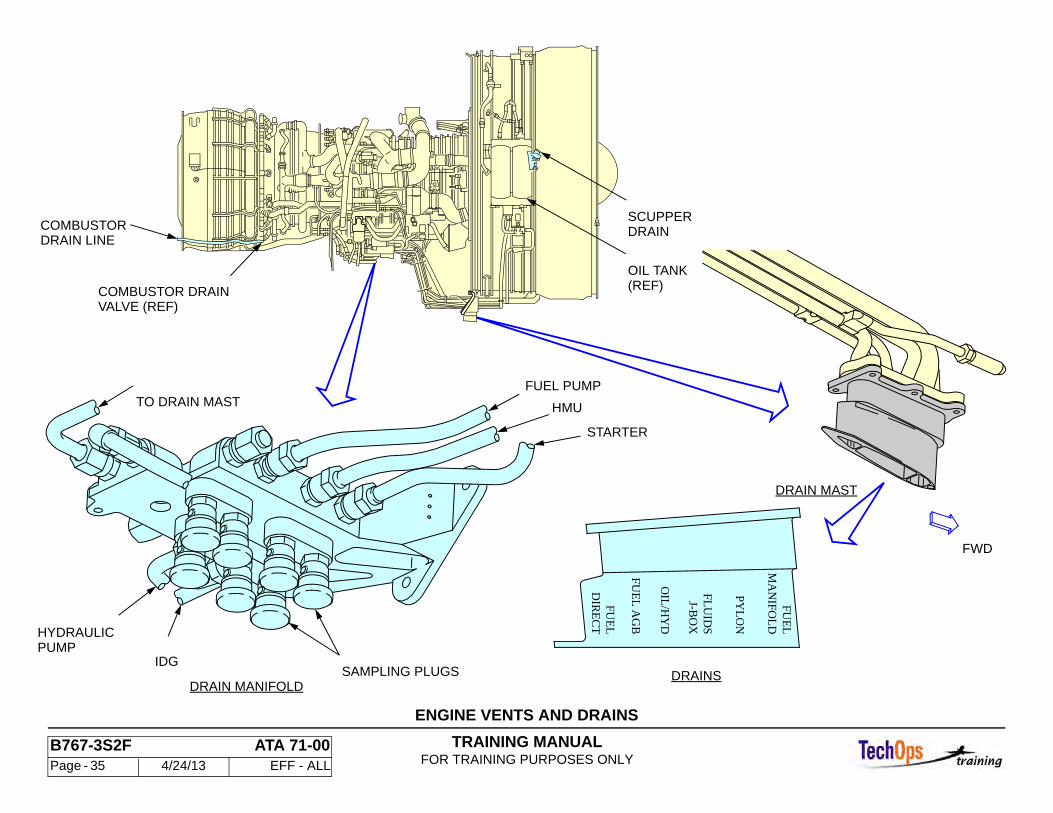
GENERAL - ENGINE VENTS AND DRAINS
Purpose
The engine vents and drains system collects and discharges drain fluids overboard.
General Description
The drain system is divided into two parts. A drain module retains fluids until expelled during flight and the drain mast discharges fluid directly overboard through the drain mast. The oil tank scupper drain and combustion chamber drain are not connected to the drain module or drain mast.
General Component Locations
The drain module is mounted to the aft side of the engine accessory gearbox. A drain mast is attached to the fan stator case and protrudes through the engine cowling into the airstream.
Drain Mast and Module
The drain module is bolted on the engine accessory gearbox lower backside and is accessed by opening the thrust reverser. The drain mast is bolted to the engine fan stator case rear underside, and extends below the fan cowl.
Drain Module
The accessories shown in the graphic have seperate drain cavities in the drain module for storing leakage. When proper airspeed is reached the spring loaded valve inside the module opens to admit air. This air flow empties the drain cavities and discharges any accumulated fuel and oil overboard through the drain mast.
The module also has push-to- open drain valves on the bottom. Each drain valve is labeled for identification. Drain valves are provided for the following components:
• Hydraulic Pump Pad • Main Fuel Pump Pad • Hydro Mechanical Unit (HMU) Mount Pad
• Starter Pad • IDG Pad
Drain Mast
An ambient air inlet port provides air flow to the drain module. The drain lines that exit directly through the main drain are
• Strut Drain • Left and Right Variable Stator Vane (VSV) actuator • Left and Right Variable Bleed Valve (VBV) actuator • Fuel Line Shroud • Fuel Drain Manifold • Forward Electrical Junction Box • IDG Pressure Relief Valve
TRAINING MANUALFOR TRAINING PURPOSES ONLY
B767-3S2F ATA 71-00 Page - 35 4/24/13 EFF - ALL
ENGINE VENTS AND DRAINS
DRAIN MAST
STARTER
DRAIN MANIFOLD
HMU
FUEL PUMP
IDG
HYDRAULICPUMP
TO DRAIN MAST
SAMPLING PLUGS DRAINS
OIL
/HY
D
J-BO
XFL
UID
S
PYL
ON
MA
NIFO
LD
FUE
L
FUE
L A
GB
DIR
EC
TFU
EL
FWD
COMBUSTOR DRAIN
DRAIN LINECOMBUSTOR
(REF)OIL TANK
DRAINSCUPPER
VALVE (REF)
TRAINING MANUALFOR TRAINING PURPOSES ONLY
B767-3S2F ATA 71-00 Page - 36 4/24/13 EFF - ALL
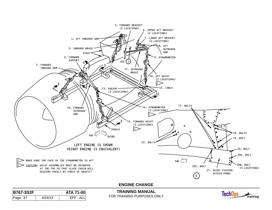
ENGINE CHANGE
Engine Removal
• Remove the fan cowl panels • Open the thrust reverser doors • Remove the core cowl doors
• Remove starter for use on engine being installed • Install cover over variable bypass valve • Disconnect Engine • Remove the engine drain mast
• Install bootstrap equipment • Disconnect the engine mounts • Perform a general visual inspection for corrosion, powerplant strut
Engine Installation
• Install new barrel nuts in the aft engine mount pylon fitting • Prepare engine mounts for engine installation • Install new serviceable mount nuts on forward engine mount • Verify the Serial Number on the serviceable tag matches the Serial number
on the engine data plate • Provide OK to install engine • Install Engine • Remove cradle from engine and lower to transport stand • Remove forward and aft bootstrap equipment • Install the bolts on each side of the strut • Install access panel for the skirt fairing • Tighten the thrust links to platform attach bolts. • Install the bolt and nut retainers on the forward mount • Inspect mount bolt installation • Install starter • Drain the starter oil, check the starter magnetic chip detector and replenish
the starter with oil • Connect thrust reverser opening hydraulic lines • Connect the strut drain line • EQ Connect the drain lines for the strut raceway • Install the drain mast • Connect the line to the pre-cooler inlet duct • Connect the hydraulic lines • Install the pneumatic starter duct
• Connect the fire extinguishing discharge flex line to the tube fitting • Connect pre-cooler inlet duct • Connect the line to the pressure regulating valve • Connect the main fuel supply line
TRAINING MANUALFOR TRAINING PURPOSES ONLY
B767-3S2F ATA 71-00 Page - 37 4/24/13 EFF - ALL
22. BOLTS
_______CAUTION: HOIST ASSEMBLIES MUST BE ORIENTED
MAKE SURE THE FACE OF THE DYNAMOMETER IS AFT
DESCEND FREELY BY FORCE OF GRAVITY AT THE TOP SO THAT SLACK CHAIN WILL
A
2. FORWARD SUPPORT
A
ARM OUTBOARD16. FORWARD
1. FORWARD INBOARD ARM
LEFT ENGINE IS SHOWN(RIGHT ENGINE IS EQUIVALENT) 20. BOLT
20B. BOLT20C. BOLT
20A. BOLT
18. BOLTS
19. BOLT
(5 LOCATIONS)
ACCESS PANEL21. SKIRT FAIRING
1
(2 LOCATIONS)14. DYNAMOMETER
FWD
17. BOLTS
A
2CRADLE
15. FORWARD HOIST (2 LOCATIONS)
10. AFT HOIST (2 LOCATIONS)
2
13. SHEAVE (2 LOCATIONS)
7. LOWER AFT BRACKET
8. AFT OUTBOARD
11. OUTBOARD BRACE
12. CABLE
(2 LOCATIONS)
6. UPPER AFT BRACKET (2 LOCATIONS)
OUTBD
9. DYNAMOMETER
ARM
FWD
D
E
D
E
2
1
STRUT
3. INBOARD BRACE
4. AFT INBOARD ARM
5. FORWARD BRACKET (2 LOCATIONS)
SEE A
ENGINE CHANGE
TRAINING MANUALFOR TRAINING PURPOSES ONLY
B767-3S2F ATA 71-00 Page - 38 4/24/13 EFF - ALL
POWERPLANT ENGINE PRESERVATION
General
The GE engine must be stored and preserved against corrosion, liquids, debris and atmospheric conditions. There are three periods of preservation:
• Up to 30 days • Up to 3 months • 3 months to 1 year.
Preservation
All engines removed from an aircraft, serviceable or unserviceable, must be preserved to the 30-day preservation procedures per the applicable Engine Maintenance Manual prior to movement into the serviceable/unserviceable engine storage areas. This preservation shall include vapor proof paper, moisture indicators and dehydrating agent even if the 30-day preservation procedures do not require it. The vapor proof paper is used to cover the intake, fan exit, and turbine exhaust. All other openings on the engine must be capped, covered, bagged, and/or protected from damage and/or contamination.
TRAINING MANUALFOR TRAINING PURPOSES ONLY
B767-3S2F ATA 71-00 Page - 39 4/24/13 EFF - ALL
ENGINE PRESERVATION
POWER PLANT - MAINTENANCE PRACTICES (PRESERVATION AND DEPRESERVATION)
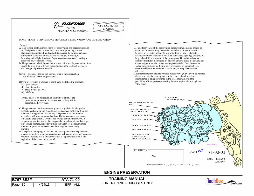
1. General A. This section contains instructions for preservation and depreservation of installed power plants. Preservation consists of protecting a power plant against corrosion, liquid and debris entering the power plant, and atmospheric conditions during periods of storage, inactivity, or following an in-flight shutdown. Depreservation consists of restoring a preserved power plant to service. B. The procedure to be followed in the preservation and depreservation of an installed power plant will vary depending upon the length of inactivity, and the type of preservation used.
NOTE: For engines that do not operate, refer to the preservation procedures in the GE Engine Manual.
(1) The preservation procedure is based upon the following schedule: (a) Up to 30 days. (b) Up to 3 months. (c) Three months to 1 year (d) Indefinite.
NOTE: There is no restriction on the number of times the preservation procedure can be renewed, as long as it is accomplished every year.
C. The procedures in this section are given as a guide in deciding what precautions should be exercised to provide adequate protection from the elements during periods of inactivity. The power plant preservation schedule is a flexible program that should be implemented in a manner which suits the particular weather and storage conditions involved. A program for inactive power plants exposed to high humidity and/or large temperature changes, especially if near salt water, would require more attention to preservation needs than those engines stored in dry climates. D. The preservation program for inactive power plants must be planned in advance to implement the preservation renewal requirements, and monitored regularly to assure that the required action is implemented prior to the expiration of the preservation period.
E. The effectiveness of the preservation measures implemented should be evaluated for determining the need to extend or shorten the periods between preservation action. To be most effective, power plants in nacelles should be desiccated, and inlet and exhaust openings plugged, to help dehumidify the interior of the power plant. Humidity indicators might be helpful in monitoring moisture conditions inside the power plant even though the nacelle cannot be completely sealed from the weather.F. When desiccants are used, they must be changed on a regular basis, determined by the environmental conditions, to keep the desiccant effective.G. It is recommended that the variable bypass valve (VBV) doors be pumped closed any time the power plant is to be preserved and stored or maintenance is being performed in the area. This will avoid the possibility of foreign objects entering the core engine inlet through the VBV doors.
EFFECTIVITY71-00-03
ALLH01A Page 202
Apr 22/07BOEING PROPRIETARY - Copyright (C) - Unpublished Work - See title page for details.
767-400MAINTENANCE MANUAL
ENGINESCF6-80C2 SERIES
wdmt-71-00-0017
ACCESSORYGEARBOX (REF)
METERING VALVEHEAD SENSOR
VSV ROD PORT
VSV HEAD PORT
UPPER PCB PORT
VBV OPEN PORT
PCR REGULATEDREFERENCEPRESSURE PORT
FWD
HYDROMECHANICALUNIT
TRAINING MANUALFOR TRAINING PURPOSES ONLY
B767-3S2F ATA 79-00 Page - 40 4/24/13 EFF - ALL
OIL SYSTEM - DISTRIBUTION SYSTEM OPERATION
System Control
The engine oil distribution system is completely automatic in operation.
Pressure Oil Flow
Engine oil which is stored in the oil tank flows by gravity through the supply inlet screen to the lube and scavenge pump. The pressure pump element of the lube and scavenge pump provides the motive force for lubricating and cooling the engine bearings and gears. The oil flows from this pressure pump, through the lube filter. (An oil filter service shutoff valve is provided for filter maintenance.) From the oil filter the oil flows up through a gravity loop (which keeps the oil from flowing from the tank to the bearings after engine shutdown) and out to the bearings and gears.
Lubrication and Cooling
The oil pressure line to the A sump distributes oil to the No. 1 (ball) bearing, Nos. 2 and 3 (roller) bearings, the accessory gear drive and bearings, and the accessory gearbox. Sump A incorporates an air/oil separator.
The oil pressure line to the B and C sumps sprays oil on the No. 4 (ball), 4 (roller) and 5 (roller) bearings. Oil is sprayed on the vent tube that vents air from the B and C sumps to the A sump to reduce coking on the vent tube.
The oil pressure line to the D sump sprays oil on the No. 6 (roller) bearing.
Scavenge Oil Flow
Oil from the A sump drains down the radial drive shaft housing into the transfer gearbox where it is scavenged. A slinger-type disk pumps in the A and D sumps provide positive sump draining for high altitude operation or airplane maneuvers when scavenge would otherwise be difficult. The oil from the sumps and the gearboxes returns to the Lube and Scavenge Pump via inlet screens to the five scavenge pump elements. All scavenge oil flow from the five scavenge pump elements is combined within the pump gallery to be discharged at one common port .
From the lube and scavenge pump the scavenge oil flows under pressure past the magnetic chip detector and then through the servo fuel heater and the fuel/ oil heat exchanger. The scavenge oil flow is then cleaned by the scavenge oil filter as it returns to the oil tank. Note: The lubrication system is fully operational only when the engine is
running. It is not fully operational when the engine is motoring or wind milling. Motoring and wind milling operations do not provide adequate sump seal pressurization nor sufficient scavenge flows. Consequently, increased apparent oil consumption rates and abnormal oil hiding occur.

TRAINING MANUALFOR TRAINING PURPOSES ONLY
B767-3S2F ATA 79-00 Page - 41 4/24/13 EFF - ALL
OIL DISTRIBUTION SYSTEM OPERATION
PRSENSOROIL TEMP
~POIL FILTER
OIL FILTERSCAVENGE
D SUMP
B
PRESS XMTRENG OIL
SWITCHOIL PRESSENG LOW
HEATERSERVO FUEL
EXCHANGERFUEL/OIL
FLAME
B/C SUMP
MAGNETIC CHIP
QTYOIL
DEAERATOR
PUMPDISKSLINGER
LUBE AND SCAVENGE PUMP
PRESS
GEAR BOXTRANSFER
A SUMP
XMTRSIGHT
FILLOVER
PUMPPRESS
ANTI-STATIC LEAK VLV
ACCESSORY
RELIEFVALVE
GLASS
DETECTOR
ARRESTOR
DRAIN PLUGOIL STRAINER
MAG DETROLLER BRGBALL BRG
SCAVENGE
OIL JETVENT
SCAVENGESUPPLYPRESS
OIL LINE
PUMP OUT
PUMP IN
GEAR BOX
TRAINING MANUALFOR TRAINING PURPOSES ONLY
B767-3S2F ATA 79-00 Page - 42 4/24/13 EFF - ALL
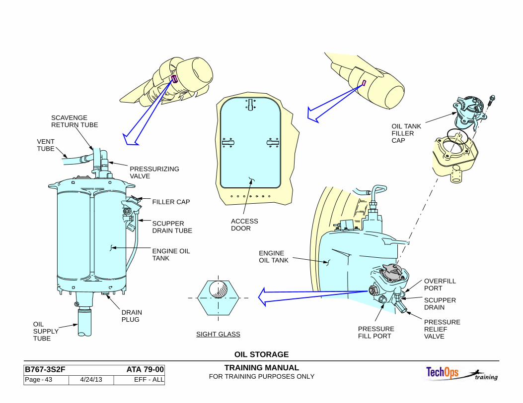
OIL SYSTEM - OIL STORAGE SYSTEM
Storage System Components
The oil storage system consists of the following components:
• Oil Tank • Oil Tank Filler Cap • Oil Tank Pressurizing Valve • Oil Tank Pressure Relief Valve
Oil Tank
The oil tank provides storage for the engine oil. It is located on the right side of the fan case. Access is gained by opening the right fan cowl panel. It is constructed of aluminum and may have an external coating of a silicone rubber compound for insulation. A plug for oil draining is provided on the bottom of the oil tank.
Oil Tank Filler Cap
The oil tank filler cap allows manual filling of the oil tank and seals the opening of the fill port. The filler cap is located on the upper right side of the oil tank. access for servicing may be gained by opening the oil tank access door located on the right fan cowl panel or by opening the right fan cowl panel.
Oil Tank Pressurizing Valve
The oil tank pressurizing valve maintains tank internal pressure. The pressurizing valve is located on top of the oil tank. Access is gained by opening the right fan cowl panel. The oil tank is pressurized by the returning air-oil stream. The oil tank pressurizing valve vents air into the A sump at 7-11 psi above the transfer gearbox vent pressure.
Pressure Relief Valve
The pressure relief valve is a back-up safety valve that relieves tank pressure. at 27 psi venting to ambient air preventing tank rupture. The relief valve is located below the fill port scupper. Access is gained by opening the right fan cowl panel.
CAUTION: DO NOT OVERFILL. IF ENGINE HAS BEEN MOTORED WITHOUT SUBSEQUENT OPERATION FOR SCAVENGING, OIL LEVEL WILL BE APPROXIMATELY TWO QUARTS (TWO LITERS) LOW.
TRAINING MANUALFOR TRAINING PURPOSES ONLY
B767-3S2F ATA 79-00 Page - 43 4/24/13 EFF - ALL
OIL STORAGE
OIL TANKFILLERCAP
OIL TANK
OVERFILLPORT
PRESSURERELIEFVALVEFILL PORT
PRESSURE
ENGINE
PRESSURIZING
SCAVENGERETURN TUBE
VENTTUBE
ENGINE OILTANK
OILSUPPLYTUBE
PLUGDRAIN
FILLER CAP
SCUPPERDRAIN TUBE
DRAINSCUPPER
DOORACCESS
SIGHT GLASS
VALVE
TRAINING MANUALFOR TRAINING PURPOSES ONLY
B767-3S2F ATA 79-00 Page - 44 4/24/13 EFF - ALL
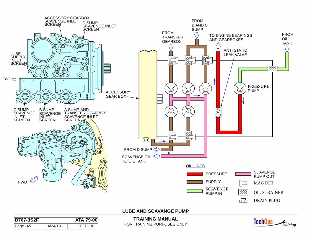
OIL SYSTEM - LUBE AND SCAVENGE PUMP
Purpose
The Lube and scavenge pump provides the motive force for the lubricating oil.
Location and Access
The lube and scavenge pump is mounted on the forward side of the accessory gearbox. It is accessible when the Thrust Reversers are open.
Characteristics
The lube and scavenge pump contains one pressure pump element and five scavenge pump elements. In the pump housing are two rows of vane type positive displacement pumps. Each row contains three pumping elements. The difference between the pumping elements is capacity which is determined by the diameter and length of each. No regulation of oil pressure is provided within the oil pump.
Power
The lube and scavenge pump is spline shaft driven by the accessory gearbox.
TRAINING MANUALFOR TRAINING PURPOSES ONLY
B767-3S2F ATA 79-00 Page - 45 4/24/13 EFF - ALL
LUBE AND SCAVANGE PUMP
FROM
SUMPB AND C
SCAVENGEPUMP IN
OIL LINES
PRESSURE
SUPPLY
TRANSFERGEARBOX
FROM
TO OIL TANKSCAVENGE OIL
PUMP OUTSCAVENGE
OIL STRAINER
DRAIN PLUG
MAG DET
FROM D SUMP
TANKOILFROM
ANTI STATICLEAK VALVE
TO ENGINE BEARINGSAND GEARBOXES
ACCESSORYGEAR BOX
PRESSUREPUMP
FWD
SCREENINLETSUPPLYLUBE
SCREENSCAVENGE INLET
SCREENSCAVENGE INLET
SCREENINLETSCAVENGE
SCREENINLETSCAVENGEB SUMP
SCREENSCAVENGE INLETTRANSFER GEARBOXA SUMP AND
FWD
D SUMPACCESSORY GEARBOX
C SUMP
TRAINING MANUALFOR TRAINING PURPOSES ONLY
B767-3S2F ATA 79-00 Page - 46 4/24/13 EFF - ALL
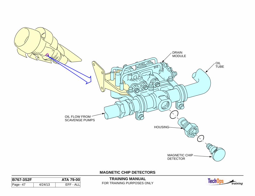
OIL SYSTEM - MAGNETIC CHIP DETECTORS
Magnetic Chip Detectors
The magnetic chip detectors attract metallic particles carried in the scavenge oil. One is provided for each scavenge pump as well as a master chip detector for all scavenge oil on return. The master chip detector is located in the scavenge discharge flow tubing adjacent to the drain module. The individual scavenge pump chip detectors are located on the inlet side of the respective scavenge pump, and are saftied to the pump with safety wire. Access is gained by opening the integrated drive generator service door or by opening the thrust reversers.
Characteristics
The magnetic chip detector is a permanent magnet probe. An internal check valve permits removal of the chip detector probe for inspection without draining the oil system.
CAUTION: WHEN REMOVING CHIP DETECTOR ENSURE A SERVICABLE “O” RING IS INSTALLED UPON INSTALLATION.
TRAINING MANUALFOR TRAINING PURPOSES ONLY
B767-3S2F ATA 79-00 Page - 47 4/24/13 EFF - ALL
MAGNETIC CHIP DETECTORS
HOUSING
MAGNETIC CHIPDETECTOR
OILTUBE
DRAINMODULE
OIL FLOW FROMSCAVENGE PUMPS
TRAINING MANUALFOR TRAINING PURPOSES ONLY
B767-3S2F ATA 79-00 Page - 48 4/24/13 EFF - ALL
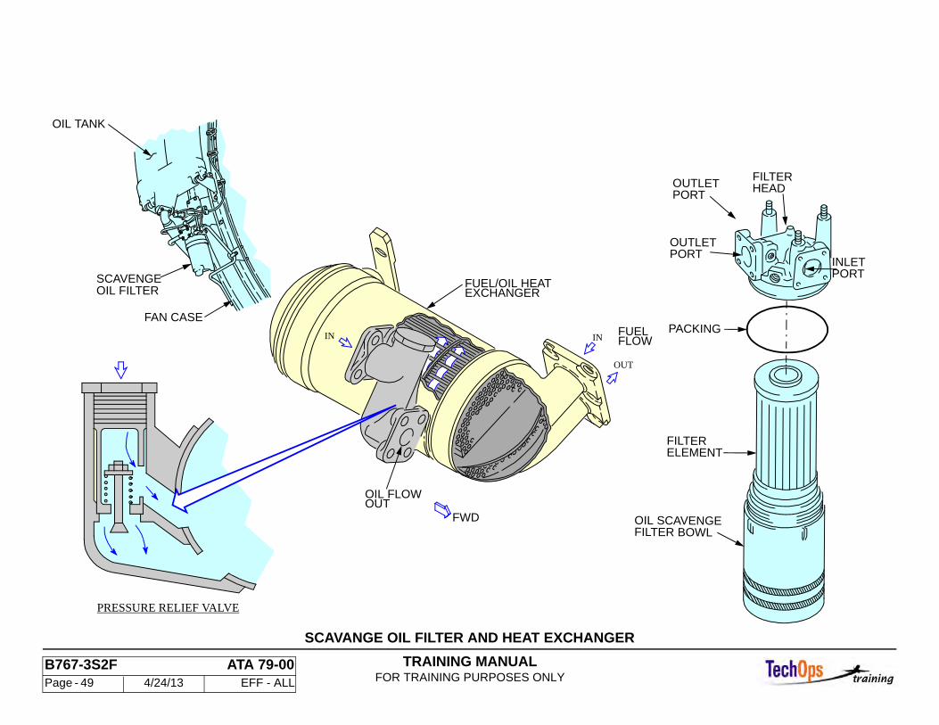
OIL SYSTEM - SCAVENGE OIL FILTER AND HEAT EXCHANGERS
Scavenge Oil Filter
The scavenge oil filter, in conjunction with the lube filter and the supply and scavenge inlet screens, clean contaminants from the oil.
Characteristics
The scavenge oil filter is of the replaceable element type. A filter relief valve is provided that begins bypassing oil at approximately 40 psid for a partially clogged filter. At 60 psid the relief valve is fully open.
The scavenge oil filter is located below the oil tank on the right side of the fan case. Access is gained by opening the right fan cowl panel.
Fuel Oil Heat Exchanger
The fuel/oil heat exchanger dissipates oil heat and heats the fuel.
Characteristics
The fuel/oil heat exchanger consists of a multi-tube core, mounted in a cylindrical housing that contains two inlet ports and two outlet ports. One set of ports is used for fuel passage through the tubes of the heat exchanger core. The other set of ports allows passage of oil around the core tubes within the housing. All engine fuel passes through the heat exchanger since there is no provision for bypass. A pressure relief valve permits scavenge oil to bypass the core tubes at engine start up during cold weather.
The fuel/oil heat exchanger is bolted to the fuel pump on the bottom right side of the engine. It is accessible when the thrust reversers are open.
Servo Fuel Heater
The servo fuel heater is used for additional heating of the fuel specifically used for hydraulic movement of components.
Characteristics
The servo fuel heater consists of a multi-tube core, mounted in a cylindrical housing that contains two inlet ports and two outlet ports. One set of ports is used for fuel passage through the tubes of the heater core. The other set of ports allows passage of oil around the core tubes within the housing.
The servo fuel heater is located on the right side of the engine at the 5:00 position. It is accessible when the right thrust reverser is open.
TRAINING MANUALFOR TRAINING PURPOSES ONLY
B767-3S2F ATA 79-00 Page - 49 4/24/13 EFF - ALL
SCAVANGE OIL FILTER AND HEAT EXCHANGER
PRESSURE RELIEF VALVE
FUELFLOWIN
OUT
FUEL/OIL HEATEXCHANGER
OIL FLOWOUT
IN
FWD
OIL FILTERSCAVENGE
FAN CASE
OIL TANK
ELEMENTFILTER
PACKING
PORTOUTLET
PORTINLET
FILTER BOWLOIL SCAVENGE
PORTOUTLET
HEADFILTER
TRAINING MANUALFOR TRAINING PURPOSES ONLY
B767-3S2F ATA 79-00 Page - 50 4/24/13 EFF - ALL
OIL SYSTEM - OIL DISTRIBUTION SYSTEM
Purpose
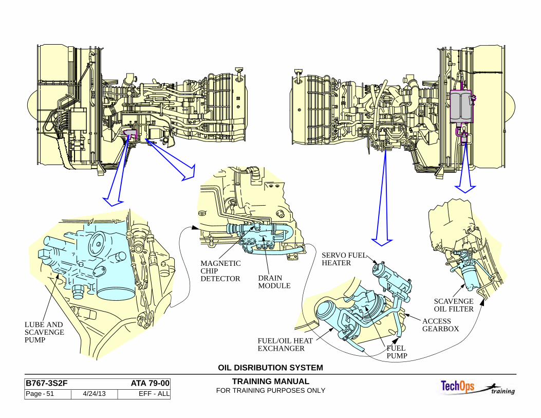
The oil distribution system provides supply and scavenge force for lubricating the engine bearings and gearboxes, for cooling the oil, and for cleaning any contaminants from the oil.
General Component Locations
The system component can be located inside the right thrust reverser and fan cowls. System components are:
• Lube and Scavenge Pump • Scavenge Oil Filter • Engine Lube Filter • Fuel/Oil Heat Exchanger • Servo Fuel Heater • Magnetic Chip Detectors
General Operation
All functions of the oil distribution system are completely automatic in operation.
TRAINING MANUALFOR TRAINING PURPOSES ONLY
B767-3S2F ATA 79-00 Page - 51 4/24/13 EFF - ALL
OIL DISRIBUTION SYSTEM
EXCHANGERFUEL/OIL HEAT
PUMPFUEL
HEATERSERVO FUEL
GEARBOXACCESS
OIL FILTERSCAVENGE
DETECTORCHIP
MODULEDRAIN
MAGNETIC
PUMPSCAVENGELUBE AND
TRAINING MANUALFOR TRAINING PURPOSES ONLY
B767-3S2F ATA 79-00 Page - 52 4/24/13 EFF - ALL
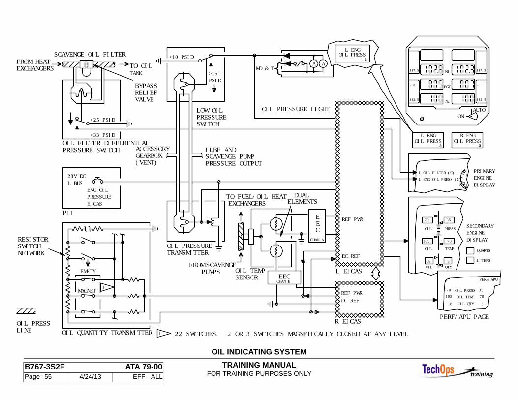
OIL SYSTEM - OIL INDICATING SYSTEM
General
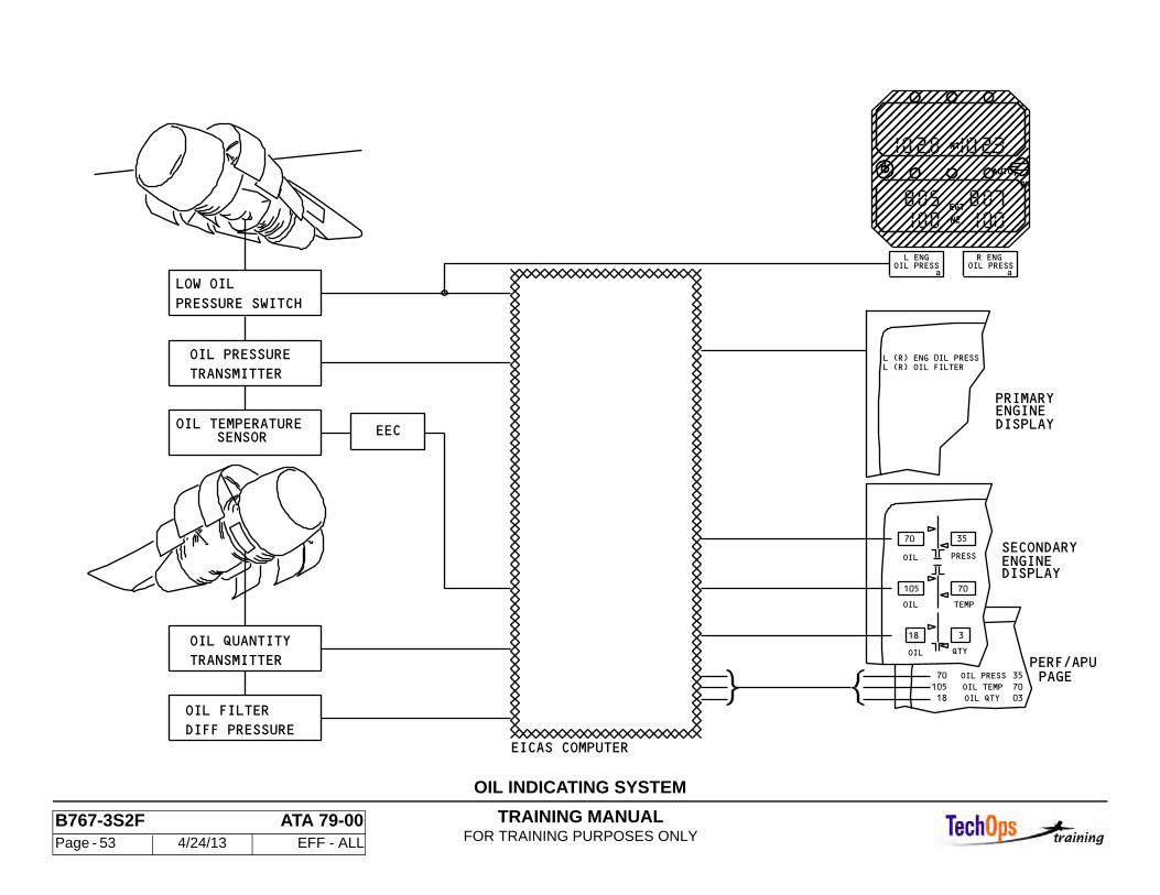
The oil indicating system includes:
• oil quantity • oil temperature • oil pressure • low oil pressure • oil filter bypass indicating
Oil indication appears on EICAS. A L(R) ENG OIL PRESS light for each engine is located below the Standby Engine Indicator.
Indications
All oil pressure indications are visible on the Secondary Engine display and the “PERF / APU” page. The engine oil temperature indication is provided to EICAS from the EEC. Also, the following messages are displayed on the primary engine display:
• L / R ENG OIL PRESS (C) • L / R OIL FILTER (C)
In the case of the “Low Oil Press” indication two engine discrete lights are located directly under the SEI. These lights indicate “L / R ENG OIL PRESS”. The lights are normally on with the engines shut down and input for these comes directly from the low oil pressure switch on the engine.
TRAINING MANUALFOR TRAINING PURPOSES ONLY
B767-3S2F ATA 79-00 Page - 53 4/24/13 EFF - ALL
N2
EGT
ON
AUTO
N1
35
03 70
35 70
3
70
EICAS COMPUTER
PAGEPERF/APU
DISPLAYENGINESECONDARY
DISPLAYENGINEPRIMARY
18
L (R) ENG 0IL PRESS
OIL
OIL QTY
L (R) OIL FILTER
a aOIL PRESS L ENG R ENG
OIL PRESS
N2
EGT
ON
AUTO
N1
OIL PRESS
OIL TEMP 18105
70
105
QTY
TEMPOIL
PRESSOIL
DIFF PRESSURE
OIL FILTER
TRANSMITTER
OIL QUANTITY
SENSOROIL TEMPERATURE
TRANSMITTER
OIL PRESSURE
PRESSURE SWITCH
LOW OIL
EEC
OIL INDICATING SYSTEM

TRAINING MANUALFOR TRAINING PURPOSES ONLY
B767-3S2F ATA 79-00 Page - 54 4/24/13 EFF - ALL
OIL SYSTEM - OIL INDICATION OPERATION
Oil Quantity
The oil quantity transmitter provides a reference signal to the EICAS computers for determining the level of oil in the tank. The oil quantity transmitter is mounted into the top of the rear half of the oil tank. Access is gained by opening right the fan cowl. Oil Quantity appears on the EICAS Secondary Engine Display and on the PERF/APU page.
The oil quantity transmitter contains a sealed liquid-level sensing unit. The sensing unit is a hollow tube containing magnetic reed switches and a resistor network, a cylindrical float houses a permanent magnet. The indicator unit is line replaceable.
Oil Pressure Transmitter
Oil pressure appears on the EICAS Secondary Engine Display and on the PERF/APU page. The oil pressure transmitter senses the differential pressure between the oil supply manifold and the accessory gearbox vent. The oil pressure transmitter is mounted on a bracket adjacent to the lube filter. Access is gained by opening the right thrust reverser.
Oil Pressure Limits
The lower red line limit for oil pressure is 10 psid. The yellow band upper limit changes between idle and full power as a linear function of N2. The yellow band upper limit is 13 psid when the engine is at low idle (60% N2). At full power (110% N2), the yellow band upper limit is 34 psid.
Low Oil Pressure Switch
The low oil pressure switch senses the differential pressure between the oil supply manifold and the accessory gearbox vent. It is bracket-mounted adjacent to the lube filter. Access is gained by opening the thrust reverser. The switch contacts are normally closed. The switch opens at 15 psid and closes at 10 psid. When the oil pressure is low, the switch illuminates the low oil pressure warning light and the message L(R) ENG OIL PRESS appears on EICAS.
Oil Temperature Sensor
The oil temperature sensor is a thermocouple probe which sends a digital signal to EICAS. Oil temperature is indicated on the EICAS secondary engine display and on the PERF/APU page.
The oil temperature (TEO) sensor contains two chromel-alumel type thermocouples. The sensor is located on the forward side of the accessory gearbox immediately inboard and below the control alternator. The sensor mounts on a T-fitting in the scavenge oil return path between the master chip detector and the lube and scavenge pump.
The operational range of the TEO sensor input to the EEC is from -81 to 352 degrees F(-63 to 178 degrees C). The red line limit is 347 degrees F (175 degrees C). The yellow band range is from 320 degrees F(160 degrees C) to the red line limit.
Oil Filter Differential Pressure Switch
The oil filter differential pressure switch is a diaphragm-controlled snap-action normally opens the switch that closes when the differential pressure across the scavenge filter element is 25 - 33 psid. The switch configuration is normally open. The switch is mounted to a bracket on the fan stator case below the oil tank and above the scavenge oil filter.
An EICAS level (C) message “L(R) OIL FILTER” appears when the switch isclosed. The EICAS message will extinguish when the switch opens at 25 psid. Or less.
TRAINING MANUALFOR TRAINING PURPOSES ONLY
B767-3S2F ATA 79-00 Page - 55 4/24/13 EFF - ALL
117.5
960
112.5
N1
N2
EGT
117.5
960
112.5
AUTOON
OIL PRESSR ENG
OIL PRESSL ENG
aa
OIL PRESSL ENG
a
OIL FILTER DIFFERENTIALPRESSURE SWITCH
FROM HEATEXCHANGERS
SCAVENGE OIL FILTER
BYPASSRELIEFVALVE
<10 PSID
>15PSID
PRESSURESWITCH
LOW OIL
TO OILTANK
L BUS
ACCESSORYGEARBOX(VENT)
LUBE ANDSCAVENGE PUMPPRESSURE OUTPUT
ENG OILPRESSUREEICAS
P11
OIL PRESSURETRANSMITTER
OIL PRESSURE LIGHT
MAGNET
EMPTY
1.
1.
PRESS
OIL TEMP
QTY
105
18
PERF/APU
35 70
3
OIL18
SECONDARYENGINEDISPLAY
PERF/APU PAGE
EXCHANGERS
FROM SCAVENGEPUMPS
RESISTORSWITCHNETWORK
70
105
OIL PRESSOIL TEMPOIL QTY
70
OIL
TO FUEL/OIL HEAT
OIL TEMPSENSOR
REF PWR
DC REF
L EICAS
R EICAS
REF PWR
DUALELEMENTS
OIL PRESSLINE
1
35
70
3
L ENG OIL PRESS (C)
MD & T
>33 PSID
OIL QUANTITY TRANSMITTER
QUARTS
LITERS
PRIMARYENGINEDISPLAY
<25 PSID
DC REF
L OIL FILTER (C)28V DC
1 22 SWITCHES. 2 OR 3 SWITCHES MAGNETICALLY CLOSED AT ANY LEVEL
AA
EEC
EEC
CHAN A
CHAN B
OIL INDICATING SYSTEM
TRAINING MANUALFOR TRAINING PURPOSES ONLY
B767-3S2F ATA 73-00 Page - 56 4/24/13 EFF - ALL
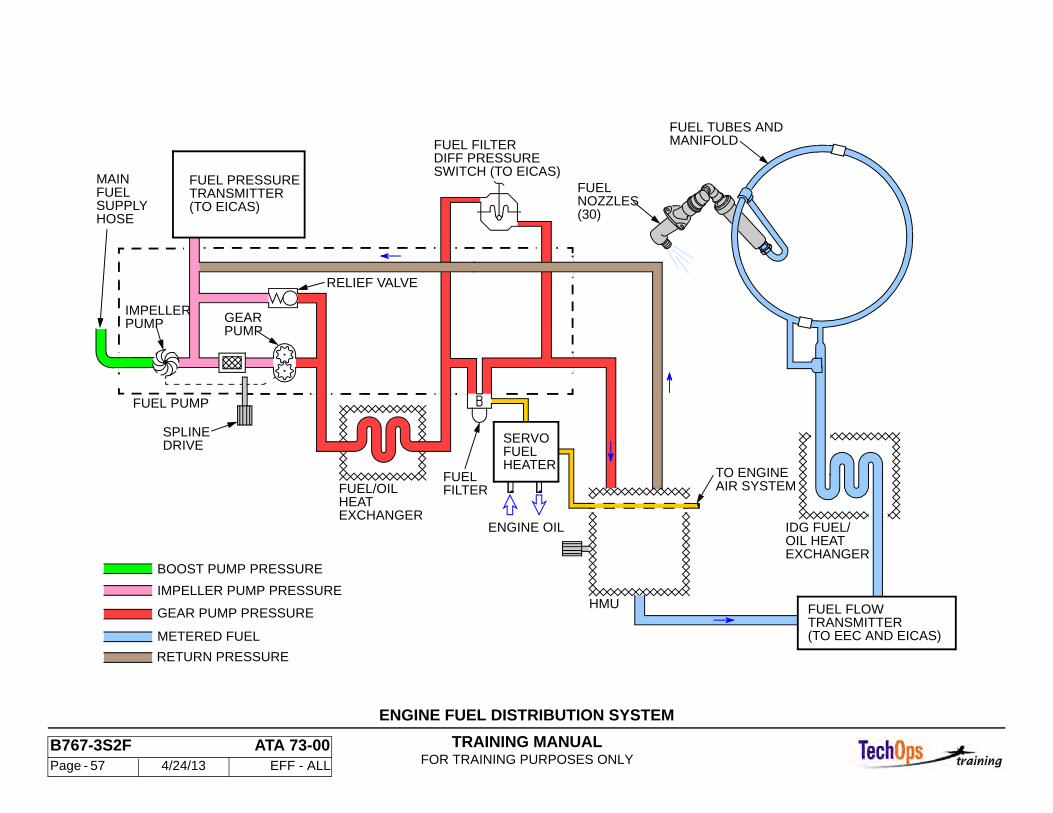
ENGINE FUEL SYSTEM - ENGINE FUEL DISTTIBUTION
General Description
The engine fuel and control system includes distribution, control, and indicating.
Distribution
The fuel distribution system receives and filters fuel from the airplane fuel tanks, and pressurizes and distributes the fuel through fuel tubes and fuel nozzles to the engine combustion section.
The system utilizes engine oil to heat the main engine control (MEC) servo fuel.
The components of the distribution system are located on the engine, these are:
• Main Fuel Supply Hose • Fuel Pump • Fuel Filter • Servo Fuel Heater • Fuel Tubes (Manifold) • Fuel Nozzles
Operation
The boost pump and gear pump pressurize fuel from the Main Supply Hose. The pressurized fuel is supplied through the Fuel/Oil Heat Exchanger and Fuel Filter to the HMU. Metered fuel from the HMU is supplied through the Fuel Flow Transmitter, IDG Fuel/Oil Heat Exchanger, and Fuel Tubes Manifold to the Fuel Nozzles.
Any fuel collected in the combustor drains through a Combustor Drain Valve when the engine is shut down.
Note: The combustor drain valve is being deleted on some CF6 engines.
Interfaces
The Servo Fuel Heater provides heated fuel for the Engine Air System. The fuel also cools the engine oil and IDG oil.
TRAINING MANUALFOR TRAINING PURPOSES ONLY
B767-3S2F ATA 73-00 Page - 57 4/24/13 EFF - ALL
ENGINE FUEL DISTRIBUTION SYSTEM
RETURN PRESSURE
METERED FUEL
IMPELLER PUMP PRESSURE
GEAR PUMP PRESSURE
BOOST PUMP PRESSURE
(TO EICAS)TRANSMITTERFUEL PRESSURE
(TO EEC AND EICAS)TRANSMITTERFUEL FLOW
IDG FUEL/OIL HEATEXCHANGER
ENGINE OIL
RELIEF VALVE
FUEL PUMP
TO ENGINEAIR SYSTEM
FUELSERVO
HEATER
HMU
FUEL/OILHEATEXCHANGER
FUELFILTER
SPLINEDRIVE
MAINFUELSUPPLYHOSE
IMPELLERPUMP GEAR
PUMP
FUELNOZZLES(30)
MANIFOLDFUEL TUBES AND
SWITCH (TO EICAS)
FUEL FILTERDIFF PRESSURE
TRAINING MANUALFOR TRAINING PURPOSES ONLY
B767-3S2F ATA 73-00 Page - 58 4/24/13 EFF - ALL
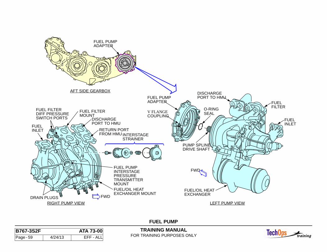
ENGINE FUEL SYSTEM - FUEL PUMP
Purpose
The fuel pump supplies pressurized fuel to the Hydro Mechanical Unit (HMU).
Location
The pump is mounted to the engine accessory gearbox with a hinged 'V' flange coupling on the aft side at the 5:00 position.
Characteristics
The pump spline drive shaft engages the wet spline of the accessory gearbox adapter. An O-ring seal on the pump shaft retains lubricating oil. A carbon seal prevents fuel leakage into the accessory gearbox adapter.
The fuel/oil heat exchanger, fuel pressure transmitter and fuel filter are mounted directly to the pump assembly. The pump has two pumping elements, a centrifugal boost element, and a fixed displacement high pressure gear element. An inter-stage strainer is designed to protect the gear pump from particle damage. Fuel outlet and bypass ports interconnect the fuel pump to the HMU. An internal relief valve prevents over-pressurization of the pump. A drain plug on the pump allows the assembly to be drained prior to disconnection.
Operation and limitations
The fuel from the airplane tanks is boosted in pressure by the boost element impeller pump sufficiently to prevent cavitation of the gear pump. This inter-stage pressure (Pb) is measurable from a port on the pump. Boost pressure is 0-152 psid, depending on RPM.
The fuel from the impeller pump flows through the inter-stage strainer to the positive-displacement gear pump. The outflow pressure is maintained below 1500-1700 psi by a relief valve.
Outflow from the gear pump flows through the externally mounted heat exchanger and fuel filter to the discharge port. Excess fuel is returned to the inter-stage section through the bypass port. Ports are provided for filter supply pressure and filter discharge pressure.
Servicing
The metal inter-stage strainer is removable for cleaning.
Removal and Installation
The fuel pump is removed from the accessory gearbox after draining the fuel lines. The fuel/oil heat exchanger and fuel filter are removed if necessary.
The pump must be supported during removal and installation to prevent damage to the seals and spline shaft (weight approximately 43 lbs.) reference the Aircraft M/M for pump installation test procedures.
ENGINE FUEL SYSTEM - FUEL FILTER
TRAINING MANUALFOR TRAINING PURPOSES ONLY
B767-3S2F ATA 73-00 Page - 59 4/24/13 EFF - ALL
FUEL PUMP
FWD
DRIVE SHAFTPUMP SPLINE
FUEL PUMPADAPTER
DISCHARGEPORT TO HMU
EXCHANGERFUEL/OIL HEAT
O-RINGV FLANGECOUPLING
LEFT PUMP VIEW
FUELFILTER
FUELINLET
FROM HMURETURN PORT
DISCHARGEPORT TO HMU
MOUNTFUEL FILTER
MOUNTTRANSMITTERPRESSUREINTERSTAGEFUEL PUMP
EXCHANGER MOUNTFUEL/OIL HEAT
FWDDRAIN PLUGSRIGHT PUMP VIEW
INTERSTAGE
SWITCH PORTSDIFF PRESSUREFUEL FILTER
AFT SIDE GEARBOX
FUEL PUMPADAPTER
FUELINLET
SEAL
STRAINER
TRAINING MANUALFOR TRAINING PURPOSES ONLY
B767-3S2F ATA 73-00 Page - 60 4/24/13 EFF - ALL
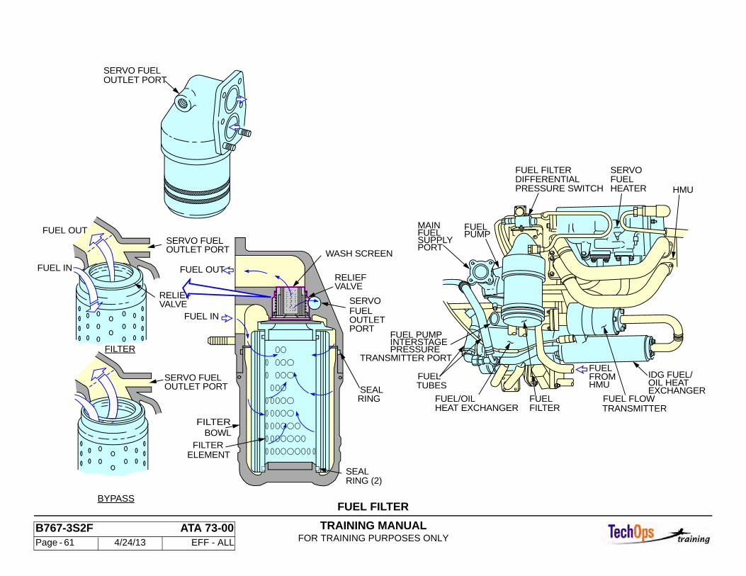
Purpose
The fuel filter removes particles from the fuel that are large enough to cause contamination/damage to the using systems.
Location
The fuel filter is bolted to flanged ports on the side of the fuel pump.
Characteristics
The filter element is a disposable unit. It is made of an epoxy impregnated inorganic glass/polyester compound, pleated and supported with a course aluminum mesh. Each end has a seal ring.
A relief valve in the filter body allows fuel to bypass an obstructed filter element at 35+/-5 psid. A wash screen with a relief valve is located in the filter body to screen the servo fuel. The relief valve opens at 15+/-5 psid.
A servo fuel outlet port is located on the filter.
Removal and Installation
The fuel filter element is reversible allowing either end to be inserted into the filter bowl during replacement. During installation the filter bowl is installed hand tight only.
ENGINE FUEL SYSTEM - SERVO FUEL HEATER
TRAINING MANUALFOR TRAINING PURPOSES ONLY
B767-3S2F ATA 73-00 Page - 61 4/24/13 EFF - ALL
FUEL FILTER
FROMFUEL
FUEL FLOWTRANSMITTER
TUBESFUEL
DIFFERENTIALPRESSURE SWITCH
FUEL FILTERFUELSERVO
HEATER
PUMPFUEL
FUEL
PORTSUPPLY
MAIN
FUEL PUMPINTERSTAGE
TRANSMITTER PORTPRESSURE
FUEL/OILHEAT EXCHANGER FILTER
FUELEXCHANGEROIL HEATIDG FUEL/
HMU
HMU
PORTOUTLET
SERVO
FUEL OUT
FUEL IN
FUEL IN
FUEL OUT
OUTLET PORTSERVO FUEL
BYPASS
FILTER
RELIEFVALVE
FILTERELEMENT
BOWLFILTER
RING (2)SEAL
RINGSEAL
VALVERELIEF
WASH SCREEN
SERVO FUELOUTLET PORT
SERVO FUELOUTLET PORT
FUEL
TRAINING MANUALFOR TRAINING PURPOSES ONLY
B767-3S2F ATA 73-00 Page - 62 4/24/13 EFF - ALL
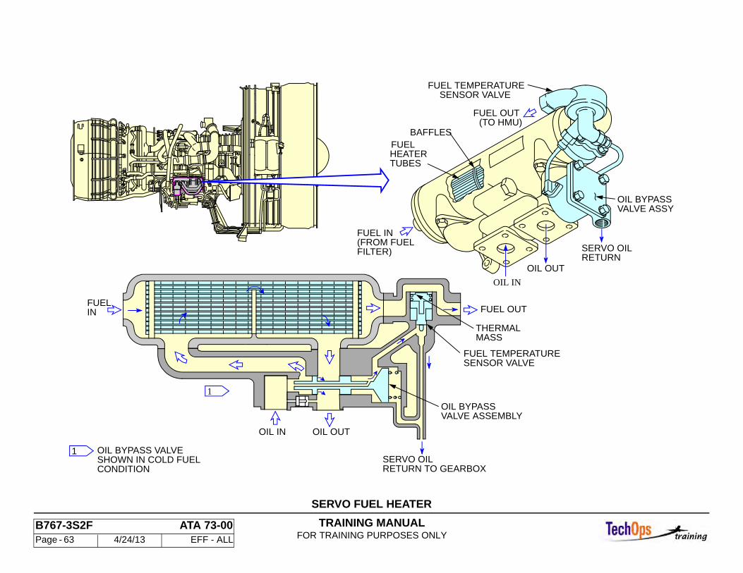
Purpose
The servo fuel heater heats the fuel used for HMU servo operations to prevent icing of the fuel.
Location
The servo fuel heater is bolted to a bracket in the accessory compartment on the right side of the Accessory Gearbox.
Characteristics
Hot oil from the engine lube system enters the heater through a relief valve assembly to flow around fuel heater tubes. The relief valve opens at 60 psid if the oil passage become blocked or attempting to start the engine in cold weather. Baffles force the oil to change direction four times before exiting the heater. Fuel passes straight through the heater tubes, without bypass, absorbing heat from the oil before exiting.
ENGINE FUEL SYSTEM - FUEL NOZZLES
TRAINING MANUALFOR TRAINING PURPOSES ONLY
B767-3S2F ATA 73-00 Page - 63 4/24/13 EFF - ALL
SERVO FUEL HEATER
OIL BYPASSVALVE ASSY
SERVO OILRETURN
SENSOR VALVEFUEL TEMPERATURE
(TO HMU)FUEL OUT
OIL OUT
OIL IN
SENSOR VALVEFUEL TEMPERATURE
VALVE ASSEMBLYOIL BYPASS
FUEL OUT
OIL OUTOIL IN
FUELIN
RETURN TO GEARBOXSERVO OIL
FUEL IN
FILTER)(FROM FUEL
FUELHEATERTUBES
BAFFLES
OIL BYPASS VALVESHOWN IN COLD FUELCONDITION
1
1
THERMALMASS
TRAINING MANUALFOR TRAINING PURPOSES ONLY
B767-3S2F ATA 73-00 Page - 64 4/24/13 EFF - ALL
Purpose
The fuel nozzles distribute and atomize the fuel within the combustion section.
Location and Access
The 30 fuel nozzles are mounted through the compressor rear frame (CRF). Access is by opening the thrust reversers.
Characteristics
The nozzles are flange-mounted to the CRF. They are numbered 1 through 30, clockwise from the top. Each nozzle includes an inlet check valve, a primary flow passage, a secondary flow passage, a flow divider valve, a heat shield, and an air shroud. There are 2 different type nozzles. Each is identified with a colored aluminum identity band on the nozzle. Nozzles with blue identity bands are used as pilot light nozzles at locations 15 and 16 only. Nozzles with aluminum color identity bands are used at all other locations.
If replacing nozzles be sure to install the proper part numbers in the proper locations.
Inlet Check Valve
The inlet check valve is closed when fuel pressure is less than 20 psid. This prevents the fuel manifold from draining into the combustor when the engine is shut down.
Primary Flow Passage
At low fuel flows, during starting and acceleration to idle, the primary flow passage is used. The flow divider valve is closed.
Fuel nozzles 15 and 16 (blue band) have richer primary flows to help prevent deceleration flameouts.
Secondary Flow Passage
As fuel flow increases with engine acceleration, the flow divider valve opens to allow fuel through the secondary flow passage.
Heat Shield The heat shield prevents excessive temperatures from reaching the flow passages.
Maintenance Practices Be certain that a fuel nozzle is replaced with the same type (color band and part number). The metallic gasket may require tape to hold it in place during installation. If tape is used, it must be removed prior to final torquing.
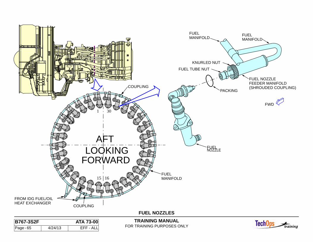
TRAINING MANUALFOR TRAINING PURPOSES ONLY
B767-3S2F ATA 73-00 Page - 65 4/24/13 EFF - ALL
FUEL NOZZLES
1 30
1615
NOZZLEFUEL
COUPLING
COUPLING
FUELMANIFOLD
FROM IDG FUEL/OILHEAT EXCHANGER
(SHROUDED COUPLING)
FUEL NOZZLEFEEDER MANIFOLD
FUELMANIFOLD
KNURLED NUT
FUELMANIFOLD
FUEL TUBE NUT
PACKING
FWD
AFTLOOKING
FORWARD
TRAINING MANUALFOR TRAINING PURPOSES ONLY
B767-3S2F ATA 73-00 Page - 66 4/24/13 EFF - ALL
ENGINE FUEL SYSTEM - FUEL FILTER BYPASS & INTER-STAGE PRESSURE TRANSMITTER
General
Fuel indicating systems fuel pump inter-stage pressure and fuel filter bypass warning. The indications can be seen on the Primary Engine Page, and the “PERF/APU” page.
Fuel Pressure Transmitter
The fuel pressure transmitter measures the inter-stage fuel pressure in the fuel pump. This indication can be viewed on the “PERF APU” page on the lower EICAS display. The fuel pressure transmitter sends an electrical analog signal to the EICAS computer system for display on the EICAS PERF/APU page.
The transmitter is an external component attached to the fuel pump adjacent to the fuel filter.
Fuel Filter Bypass Indication
The fuel filter bypass indication system provides a display in the flight compartment of excessive differential pressure across the fuel filter. The system signifies an impending filter bypass situation by using a differential pressure switch to generate an EICAS message. The system uses an EICAS status and maintenance message for indication.
The fuel filter differential pressure switch signal is sent to the EICAS computers. Fuel tubes connect the switch to the filter supply and outlet ports on the fuel pump. The fuel filter differential pressure switch is mounted by a bracket to the top of the Fuel Filter.
System Operation
When blockage of the fuel filter causes a differential pressure across the filter of 21 psid or greater, the fuel filter differential pressure switch sends a ground Signal to EICAS. EICAS then generates a C level message “L(R) ENG FUEL FILT” after a 10 second time delay.
If the differential pressure decreases to 18 psid or less, the ground signal to EICAS is removed. The filter bypass valve does not open until approximately 35 psid, therefore, the indication is for impending fuel filter bypass, and does notnecessarily indicate that bypass has occurred.
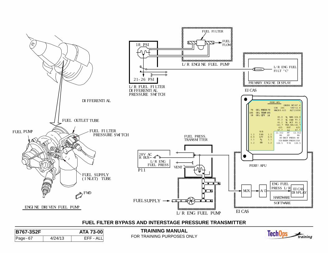
TRAINING MANUALFOR TRAINING PURPOSES ONLY
B767-3S2F ATA 73-00 Page - 67 4/24/13 EFF - ALL
FUELFLOW
L/R ENG FUEL FILT "C"
L/R ENGINE FUEL PUMP
L/R FUEL FILTER DIFFERENTIALPRESSURE SWITCH
18 PSI
FUEL FILTER
21-26 PSI
P11 VENT
EICASDISPLAYA/DMUX
SOFTWAREHARDWARE
28V ACR BUS
FUEL PRESS.TRANSMITTER
L/R ENGFUEL PRESS
FUELSUPPLY
L/R ENG FUEL PUMP
ENG FUEL PRESS L/R
(INLET) TUBE FUEL SUPPLY
FUEL FILTER
DIFFERENTIAL
PRESSURE SWITCH
FUEL OUTLET TUBE
PUMPFUEL
FWD
EICAS
EICAS
10SEC
PRIMARY ENGINE DISPLAY
PERF/APU
2
VIBFANLPTNBB
OIL QTYOIL TEMPOIL PRESS
104.081.281.2
81.2 81.2
62562567.767.7
8640350
120.5
8640350
120.5
12.31212.312
141.7141.7
85.0
T/RBURN PRESSDUCT PRESS
FPFFN2EGT
TRA SELN ACT1N CMD1N MAX1
1.10.9
1.2
1.2
1.10.9
1.2
1.2
105 10518
70
18
70 21030+12.0187.6
2450.615 ALT
TATGROSS WT
MACHCAS
PERF/APU
ENGINE DRIVEN FUEL PUMP
FUEL FILTER BYPASS AND INTERSTAGE PRESSURE TRANSMITTER
TRAINING MANUALFOR TRAINING PURPOSES ONLY
B767-3S2F ATA 73-00 Page - 68 4/24/13 EFF - ALL
ENGINE FUEL SYSTEM - FUEL FLOW INDICATION
General
The fuel flow indication system provides fuel flow indication to the flight crew in LBS/ph. These indications are also delivered to the FMS for fuel economy calculations. The system is operated completely automatically.
System Operation
The time interval between start and stop pulses is measured by the EICAS computers, and converted to fuel flow rate. this information is sent to the EICAS computer by the EEC. The resulting fuel flow is displayed on the secondary engine display on EICAS. the measurement is read in KG/ph and LBS/ph as programed by the EICAS computers programing. This indication can also be viewed in a digital format on the “PERF/APU” maintenance page.
Interfaces
A digital signal of the flow rate is sent from EICAS to the FMC. The FMC uses fuel flow to calculate a total fuel quantity for comparison with the FQIS total.
Normal fuel flow is 500 to 600 LBS/ph (227 KG/ph) at engine ignition light-off. Fuel flow at idle should be approximately 1279 to 1588 LBS/ph (580-720 KG/ph).
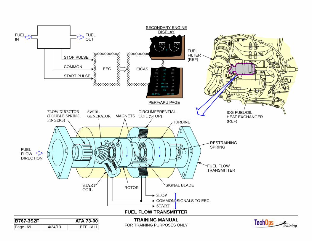
TRAINING MANUALFOR TRAINING PURPOSES ONLY
B767-3S2F ATA 73-00 Page - 69 4/24/13 EFF - ALL
FUEL FLOW TRANSMITTER
PERF/APU PAGE
STOP PULSE
START PULSE
FUELIN
FUELOUT
COMMON
DISPLAYSECONDARY ENGINE
EICASEEC
RESTRAININGSPRING
FUEL FLOWTRANSMITTER
CIRCUMFERENTIAL
TURBINE
STOP
START
COIL (STOP)
SIGNAL BLADE
COMMON SIGNALS TO EEC
MAGNETS
ROTOR
SWIRLGENERATOR
STARTCOIL
(DOUBLE SPRINGFINGERS)
FUELFLOWDIRECTION
FLOW DIRECTOR IDG FUEL/OILHEAT EXCHANGER(REF)
FUELFILTER(REF)
428EGT
26.5
1.705
35
40
390
120.5
73.2
4.310
75
40
390
-90.1
428
FF
FP
DUCT PR
BURN PR
T/R
EGT REDOIL T YEL
N2
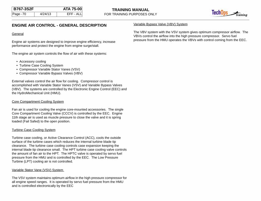
TRAINING MANUALFOR TRAINING PURPOSES ONLY
B767-3S2F ATA 75-00 Page - 70 4/24/13 EFF - ALL
ENGINE AIR CONTROL - GENERAL DESCRIPTION
General
Engine air systems are designed to improve engine efficiency, increase performance and protect the engine from engine surge/stall.
The engine air system controls the flow of air with these systems:
• Accessory cooling • Turbine Case Cooling System • Compressor Variable Stator Vanes (VSV) • Compressor Variable Bypass Valves (VBV)
External valves control the air flow for cooling. Compressor control is accomplished with Variable Stator Vanes (VSV) and Variable Bypass Valves (VBV). The systems are controlled by the Electronic Engine Control (EEC) and the HydroMechanical Unit (HMU).
Core Compartment Cooling System
Fan air is used for cooling the engine core-mounted accessories. The single Core Compartment Cooling Valve (CCCV) is controlled by the EEC. Engine 11th stage air is used as muscle pressure to close the valve and it is spring loaded (Fail Safed) to the open position.
Turbine Case Cooling System
Turbine case cooling, or Active Clearance Control (ACC), cools the outside surface of the turbine cases which reduces the internal turbine blade tip clearance. The turbine case cooling controls case expansion keeping the internal blade tip clearance small. The HPT turbine case cooling valve controls the amount of fan air to the HPT. The HPTC valve is operated by servo fuel pressure from the HMU and is controlled by the EEC. The Low Pressure Turbine (LPT) cooling air is not controlled.
Variable Stator Vane (VSV) System
The VSV system maintains optimum airflow in the high pressure compressor for all engine speed ranges. It is operated by servo fuel pressure from the HMU and is controlled electronically by the EEC
Variable Bypass Valve (VBV) System
The VBV system with the VSV system gives optimum compressor airflow. The VBVs control the airflow into the high pressure compressor. Servo fuel pressure from the HMU operates the VBVs with control coming from the EEC.
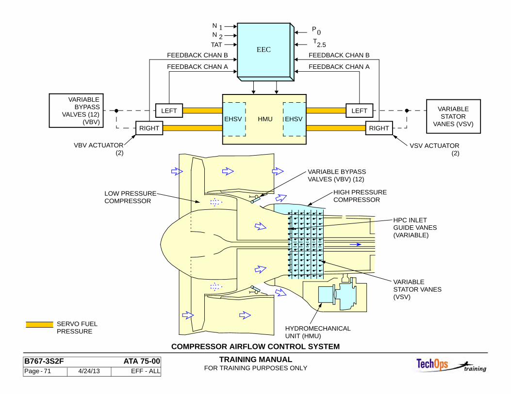
TRAINING MANUALFOR TRAINING PURPOSES ONLY
B767-3S2F ATA 75-00 Page - 71 4/24/13 EFF - ALL
COMPRESSOR AIRFLOW CONTROL SYSTEM
COMPRESSOR
(VSV)
VARIABLE
HPC INLETGUIDE VANES(VARIABLE)
VALVES (VBV) (12)VARIABLE BYPASS
HIGH PRESSURECOMPRESSOR
LOW PRESSURE
HYDROMECHANICALUNIT (HMU)
FEEDBACK CHAN B
FEEDBACK CHAN A
FEEDBACK CHAN B
FEEDBACK CHAN A
VSV ACTUATOR
VARIABLESTATOR
VANES (VSV)
VARIABLEBYPASS
(VBV) EHSVHMU
VBV ACTUATOR
EHSV
EECTAT
PN
N 1 2
T 2.5
0
PRESSURESERVO FUEL
LEFT
RIGHT
STATOR VANES
VALVES (12)LEFT
RIGHT
(2) (2)
TRAINING MANUALFOR TRAINING PURPOSES ONLY
B767-3S2F ATA 75-00 Page - 72 4/24/13 EFF - ALL
ENGINE AIR CONTROL - VARIABLE BYPASS VALVES
General
The Variable Bypass Valves (VBVs) control the HPC inlet airflow. The 12 valves use hydraulic actuators. Servo fuel from the HMU is used as the hydraulic fluid to operate the actuators, scheduling is controlled by the EEC.
The VBV components are located in the fan frame. Twelve valves are modulated in unison by two actuators. The VBVs are open at low power and move toward closed as power increases. The open valves divert a portion of the LPC primary discharge from the HPC to the secondary flow path.
Each VBV actuator has a Linear Variable Differential Transformer (LVDT) to send feedback signals to the EEC. The actuator LVDTs on the left side of the engine are excited by and send feedback signals to EEC channel A. The right side actuator LVDTs are excited by and send feedback signals to EEC channel B.
General Operation
The EEC uses input signals from engine sensors to control Electro-Hydraulic Servo Valves (EHSVs) on the HMU. The EHSVs use servo fuel to move the VBV actuators. The two actuators are connected by a unison ring to all 12 VBV’s. The EEC increases signal current to the EHSV in proportion to N2. The EHSV sends servo fuel pressure to the actuators to move them to the commanded position.
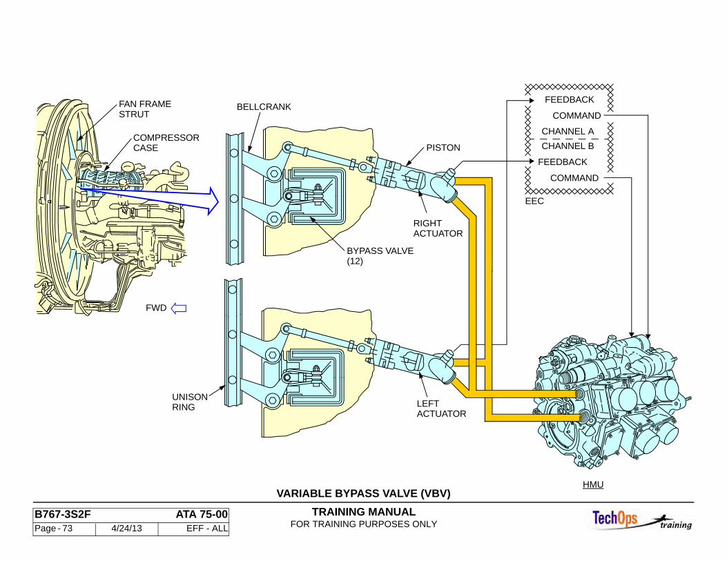
TRAINING MANUALFOR TRAINING PURPOSES ONLY
B767-3S2F ATA 75-00 Page - 73 4/24/13 EFF - ALL
VARIABLE BYPASS VALVE (VBV)
COMMAND
FEEDBACK
COMMAND
CHANNEL A
CHANNEL B
FEEDBACK
EEC
BYPASS VALVE(12)
BELLCRANK
PISTON
RINGUNISON
LEFTACTUATOR
RIGHTACTUATOR
HMU
STRUTFAN FRAME
CASECOMPRESSOR
FWD
TRAINING MANUALFOR TRAINING PURPOSES ONLY
B767-3S2F ATA 75-00 Page - 74 4/24/13 EFF - ALL
ENGINE AIR CONTROL - VARIABLE STATOR VANE SYSTEM
Introduction
Two VSV actuators position the stator vanes to control the airflow through the HPC to prevent compressor surge.
Access to the VSV system components is under the thrust reverser halves.
General
The VSV system components include these components:
• Two actuators • Two actuation levers • Six actuation rings connected to VSV lever arms
VSV Actuators
The VSV actuators are a double-action piston type located at the 3:00 and 9:00 positions on the HPC case forward flange.
Operation
The Variable Stator Vanes (VSVs) control the HPC airflow. Both valves use hydraulic actuators. Servo fuel from the HMU is used as the hydraulic fluid to operate the actuators, scheduling is controlled by the EEC.
The VSV include the HPC inlet guide vanes and the first five stages of the HPC stator vanes. Modulation of these vanes permits optimum compressor performance throughout the engine operating range. The VSV components are on the forward HPC case. The VSVs are varied in unison by two VSV actuators. They are closed at low power and modulate open as power increases.
An electrical connector on each actuator provides position feedback to the EEC from an LVDT inside the actuator. The left actuator LVDT is excited by and sends position feedback signals to EEC channel A. The right actuator LVDT is excited by and sends position feedback signals to EEC channel B.
MAINTENANCE TIP
The actuator guide can only be fitted to the actuator lever one way. The word AFT is embossed on the rear of the actuator to ensure proper installation.
If the actuator is not installed properly, the engine will surge when operated.
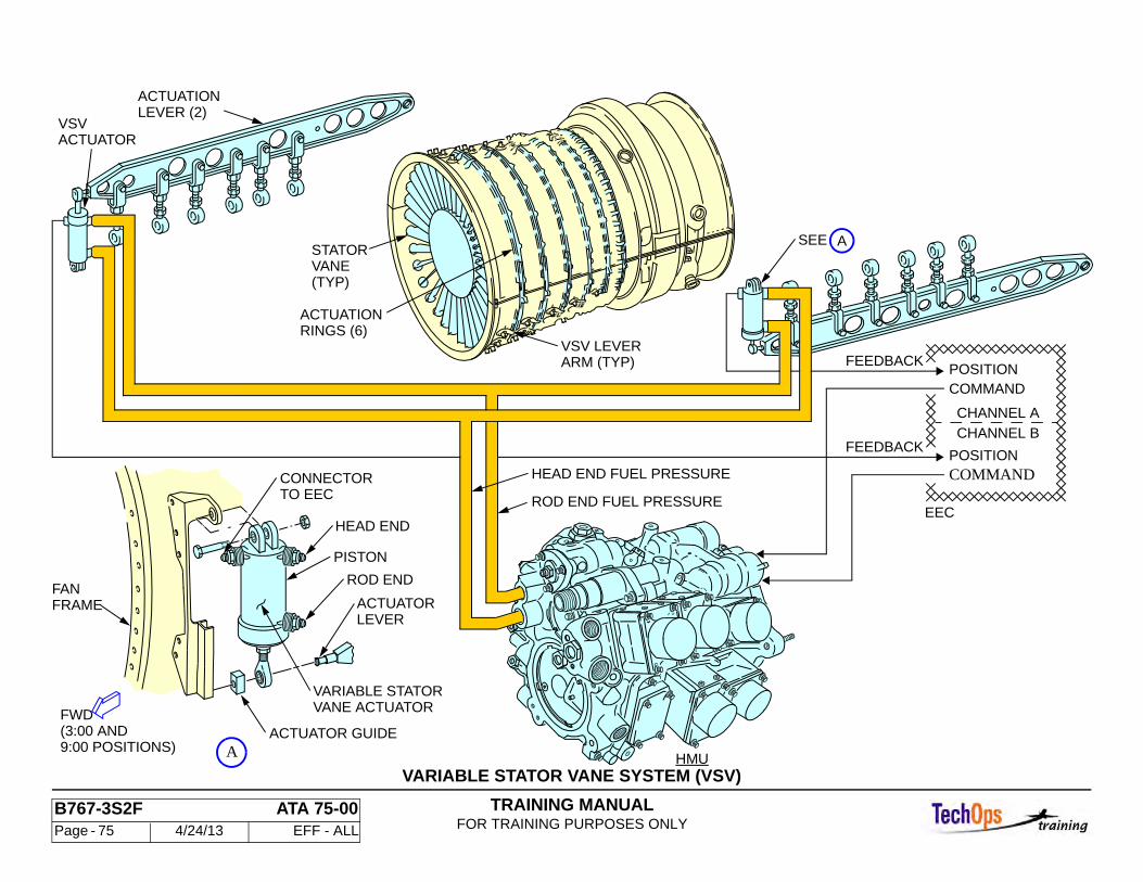
TRAINING MANUALFOR TRAINING PURPOSES ONLY
B767-3S2F ATA 75-00 Page - 75 4/24/13 EFF - ALL
VARIABLE STATOR VANE SYSTEM (VSV)
A
EEC
CHANNEL A
CHANNEL B
POSITIONCOMMAND
POSITIONCOMMAND
HEAD END FUEL PRESSURE
VARIABLE STATOR
ARM (TYP)VSV LEVER
(TYP)VANESTATOR
HMU
FANFRAME
FWD VANE ACTUATOR
ACTUATOR GUIDE
PISTON
ROD END
HEAD END
LEVERACTUATOR
CONNECTORTO EEC
ACTUATORVSV
LEVER (2)ACTUATION
RINGS (6)ACTUATION
(3:00 AND9:00 POSITIONS)
ASEE
FEEDBACK
FEEDBACK
ROD END FUEL PRESSURE
TRAINING MANUALFOR TRAINING PURPOSES ONLY
B767-3S2F ATA 75-00 Page - 76 4/24/13 EFF - ALL
ENGINE AIR CONTROL - VSV AND VBV CONTROL
General
The logic schedule for VSV and VBV control are incorporated into the EEC software. The VSV’s are modulated as a function of actual N2, T2.5, and PO. The VSV’s are modulated as a function of actual N1. TAT, and VSV positions.
When the engine is started, the VBV’s are open and the VSV’s are closed. As the engine accelerates, the EEC commands the EHSV to signal the VSV actuators to gradually open the vanes. The position feedback signal tells the EEC that the actuators have moved to the commanded position. The VSV position is also used by the EEC to schedule the position of the VBV’s. The VBV actuators get fuel pressure signals to gradually close as power increases. At high power, the VSV’s are fully open and the VBV’s are fully closed. The opposite occurs during power reductions.
Modulation Schedule Revisions
The EEC increases compressor stall margin during rapid decelerations ( throttle chop) and reverse thrust operations.
Rapid decelerations are sensed by the EEC. The large mass of the fan does not decelerate as quickly as the high pressure compressor. This causes an overload of airflow at the HPC inlet. To prevent a compressor stall, the EEC revises the normal VBV schedule so that the VBV’s are opened an additional 30 square inches. When the EEC senses that the decelerations of the fan and compressor have stabilized, it returns to the normal VBV schedule.
During reverse thrust operation, the reversed fan air disturbs the airflow at the engine inlet. To ensure the engine does not stall, the EEC revises the normal VBV schedule so that the VBV’s are open an additional 30 square inches until reverse thrust is stopped.
The VSV’s are closed an additional four degrees from the normal schedule during reverse thrust.
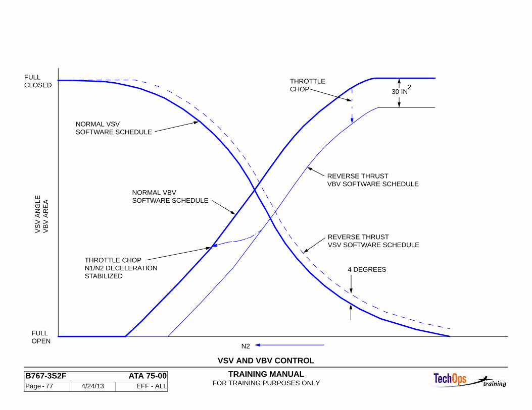
TRAINING MANUALFOR TRAINING PURPOSES ONLY
B767-3S2F ATA 75-00 Page - 77 4/24/13 EFF - ALL
VSV AND VBV CONTROL
VSV SOFTWARE SCHEDULE
VBV SOFTWARE SCHEDULEREVERSE THRUST
REVERSE THRUST
4 DEGREES
NORMAL VBV
SOFTWARE SCHEDULENORMAL VSV
SOFTWARE SCHEDULE
STABILIZEDN1/N2 DECELERATIONTHROTTLE CHOP
FULLCLOSED
FULLOPEN
N2
230 INCHOP
THROTTLE
VB
V A
RE
AV
SV
AN
GL
E
TRAINING MANUALFOR TRAINING PURPOSES ONLY
B767-3S2F ATA 75-00 Page - 78 4/24/13 EFF - ALL
ENGINE AIR CONTROL - ENGINE COOLING SYSTEMS
General
The engine cooling system controls the flow of air for these components:
• Accessory cooling • Turbine Case Cooling
External valves control the air flow for cooling. The systems are controlled by the Electronic Engine Control (EEC) and the HydroMechanical Unit (HMU). A single Core Compartment Cooling Valve (CCCV) is operated for core cooling. Also, a single High Pressure Turbine Cooling Valve (HPTCV) is operated to cool HPT case.
Note: The LPT case is cooled continuously throughout the full range of engine operation. There is no control valve provided for this operation.
Core Compartment Cooling System
Fan air is used for cooling the engine core-mounted accessories. The single Core Compartment Cooling Valve (CCCV) is controlled by the EEC and operated using 11th stage muscle air pressure.
Turbine Case Cooling System
Turbine case cooling, or active clearance control, cools the outside surface of the turbine cases which reduces the internal turbine blade tip clearance. The turbine case cooling controls case expansion keeping the internal blade tip clearance small thus improving engine efficiency. The HPT turbine case cooling valve controls the amount of fan air to the HPT. The HPTC valve is operated by servo fuel pressure from the HMU which is controlled electronically by the EEC.
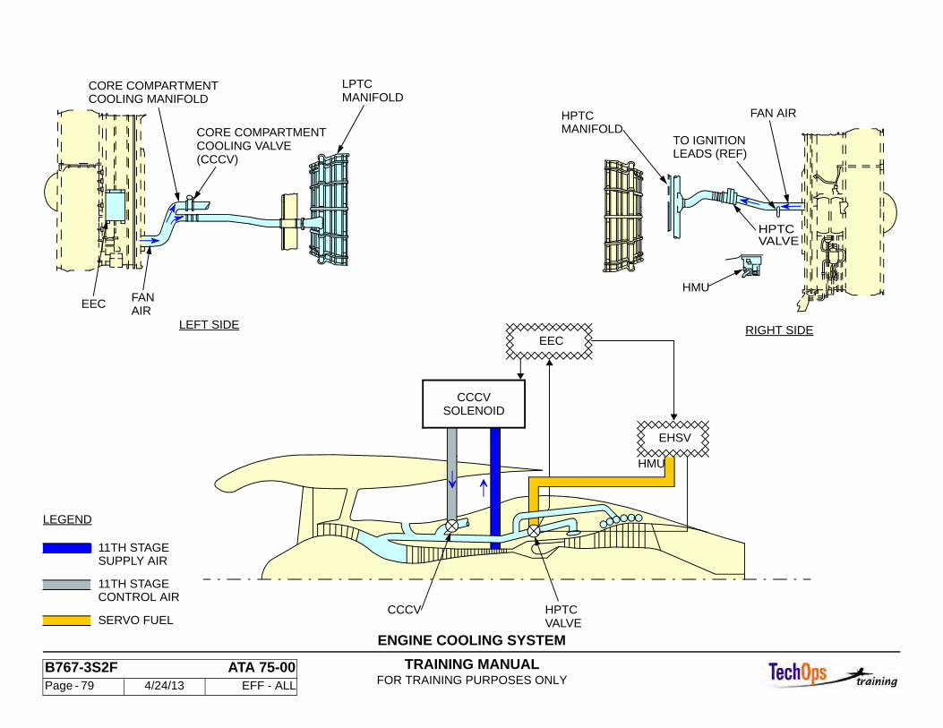
TRAINING MANUALFOR TRAINING PURPOSES ONLY
B767-3S2F ATA 75-00 Page - 79 4/24/13 EFF - ALL
ENGINE COOLING SYSTEM
RIGHT SIDELEFT SIDE
CCCV
EEC
LEADS (REF)TO IGNITION
FAN AIR
HPTC VALVE
HMU
HPTCMANIFOLD
LPTCMANIFOLD
CORE COMPARTMENTCOOLING VALVE(CCCV)
COOLING MANIFOLDCORE COMPARTMENT
EHSV
FANAIR
LEGEND
11TH STAGESUPPLY AIR
11TH STAGECONTROL AIR
SERVO FUEL
SOLENOID
HPTCVALVE
CCCV
HMU
EEC
TRAINING MANUALFOR TRAINING PURPOSES ONLY
B767-3S2F ATA 75-00 Page - 80 4/24/13 EFF - ALL
ENGINE AIR CONTROL - COMPRESSOR DISCHARGE TEM-PERATURE SENSOR (T3)
General
The T3 sensor measures HPC discharge air temperature. The EEC uses this temperature to sequence the HPTC active clearance control valve.
The T3 temperature sensor is mounted to the forward end of the compressor rear frame at the 11:30 position. The T3 sensor has dual chromel/alumel thermocouples, one for each engine EEC channel. A single electrical connector sends both outputs to the cold junctions inside the EEC. The connector is located above the EGT shunt junctions box on a bracket on the LPT cooling air tube. The outputs from the T3 sensor go to the connector through a metal cased ceramic sheathed lead.
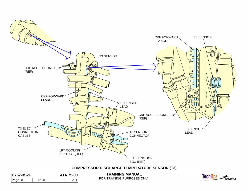
TRAINING MANUALFOR TRAINING PURPOSES ONLY
B767-3S2F ATA 75-00 Page - 81 4/24/13 EFF - ALL
COMPRESSOR DISCHARGE TEMPERATURE SENSOR (T3)
CONNECTORT3 SENSOR
T3 ELECCONNECTORCABLES
AIR TUBE (REF)LPT COOLING
EGT JUNCTIONBOX (REF)
LEADT3 SENSOR
CRF FORWARDFLANGE
CRF ACCELEROMETER(REF)
FLANGECRF FORWARD
(REF)CRF ACCELEROMETER
T3 SENSOR
T3 SENSORLEAD
T3 SENSOR
TRAINING MANUALFOR TRAINING PURPOSES ONLY
B767-3S2F ATA 75-00 Page - 82 4/24/13 EFF - ALL
ENGINE AIR CONTROL - CORE COMPARTMENT COOLING VALVE CONTROL
Valve Operation
The EEC controls the flow of eleventh stage air used to close the CCCV through the CCCV solenoid. The solenoid has two electrically independent coils. Each is controlled by a different channel of the EEC. There is no position feedback from the CCCV. The EEC energizes the CCCV solenoid to close the valve during these conditions:
• N1 is greater than 86 percent • Ambient pressure is less than 7.95 psia (17,000 foot altitude) • T49 (EGT) is less than 699C • Engine acceleration rate is less then 70 RPM per second • Commanded N2 is not more than five percent more than the actual N2
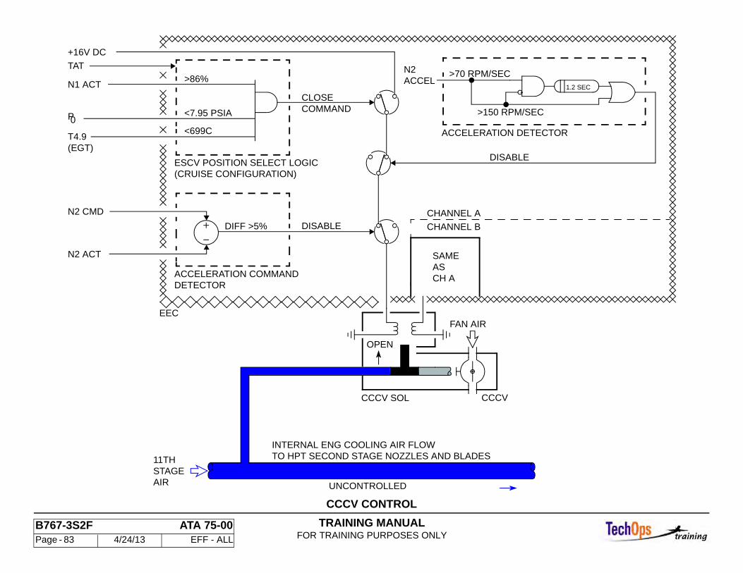
TRAINING MANUALFOR TRAINING PURPOSES ONLY
B767-3S2F ATA 75-00 Page - 83 4/24/13 EFF - ALL
CCCV CONTROL
FAN AIR
DETECTOR
DISABLE
EEC
DIFF >5%
ACCELERATION COMMAND
OPEN
DISABLE
>150 RPM/SEC
>70 RPM/SEC
ACCELERATION DETECTOR<699C
<7.95 PSIA
>86%
ESCV POSITION SELECT LOGIC
1.2 SEC
(CRUISE CONFIGURATION)
+16V DC
TAT
(EGT)T4.9
0P
N2 CMD
N1 ACT
N2 ACT SAME
CHANNEL A
CHANNEL B
AS CH A
ACCELN2
COMMANDCLOSE
TO HPT SECOND STAGE NOZZLES AND BLADESINTERNAL ENG COOLING AIR FLOW
AIRSTAGE11TH
UNCONTROLLED
CCCV SOL CCCV
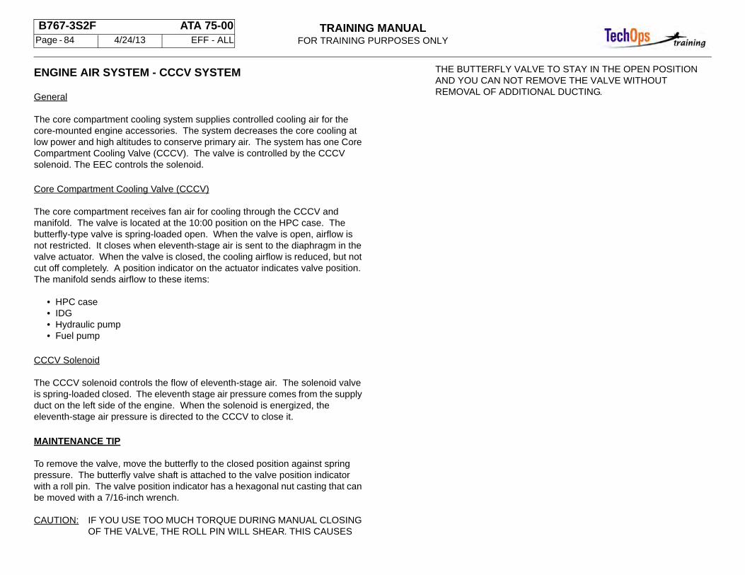
TRAINING MANUALFOR TRAINING PURPOSES ONLY
B767-3S2F ATA 75-00 Page - 84 4/24/13 EFF - ALL
ENGINE AIR SYSTEM - CCCV SYSTEM
General
The core compartment cooling system supplies controlled cooling air for the core-mounted engine accessories. The system decreases the core cooling at low power and high altitudes to conserve primary air. The system has one Core Compartment Cooling Valve (CCCV). The valve is controlled by the CCCV solenoid. The EEC controls the solenoid.
Core Compartment Cooling Valve (CCCV)
The core compartment receives fan air for cooling through the CCCV and manifold. The valve is located at the 10:00 position on the HPC case. The butterfly-type valve is spring-loaded open. When the valve is open, airflow is not restricted. It closes when eleventh-stage air is sent to the diaphragm in the valve actuator. When the valve is closed, the cooling airflow is reduced, but not cut off completely. A position indicator on the actuator indicates valve position. The manifold sends airflow to these items:
• HPC case • IDG • Hydraulic pump • Fuel pump
CCCV Solenoid
The CCCV solenoid controls the flow of eleventh-stage air. The solenoid valve is spring-loaded closed. The eleventh stage air pressure comes from the supply duct on the left side of the engine. When the solenoid is energized, the eleventh-stage air pressure is directed to the CCCV to close it.
MAINTENANCE TIP
To remove the valve, move the butterfly to the closed position against spring pressure. The butterfly valve shaft is attached to the valve position indicator with a roll pin. The valve position indicator has a hexagonal nut casting that can be moved with a 7/16-inch wrench.
CAUTION: IF YOU USE TOO MUCH TORQUE DURING MANUAL CLOSING OF THE VALVE, THE ROLL PIN WILL SHEAR. THIS CAUSES
THE BUTTERFLY VALVE TO STAY IN THE OPEN POSITION AND YOU CAN NOT REMOVE THE VALVE WITHOUT REMOVAL OF ADDITIONAL DUCTING.
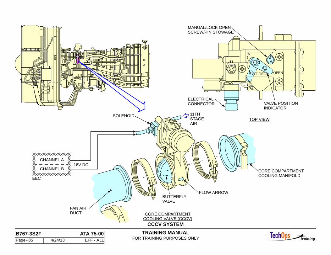
TRAINING MANUALFOR TRAINING PURPOSES ONLY
B767-3S2F ATA 75-00 Page - 85 4/24/13 EFF - ALL
CCCV SYSTEMCOOLING VALVE (CCCV)CORE COMPARTMENT
MANUAL/LOCK OPENSCREW/PIN STOWAGE
VALVE POSITIONINDICATOR
ELECTRICALCONNECTOR
11THSTAGEAIR
BUTTERFLYVALVE
FAN AIRDUCT
CHANNEL B
CHANNEL A
SOLENOID
16V DC
EEC
TOP VIEW
FLOW ARROW
OPENCLOSED
CORE COMPARTMENTCOOLING MANIFOLD

TRAINING MANUALFOR TRAINING PURPOSES ONLY
B767-3S2F ATA 75-00 Page - 86 4/24/13 EFF - ALL
ENGINE AIR - TURBINE CASE COOLING
Introduction
The turbine case cooling (active clearance control) system uses separate manifolds to cool the LPT and HPT cases. The HPTC valve controls the fan air to the HPT manifold. There is no valve for the LPTC manifold. The LPTC and HPTC manifolds send fan air onto their respective turbine cases. This decreases case expansion which decreases turbine blade tip-to-case clearance and increases turbine efficiency.
Description
The HPTC valve is located on the right side of the engine at the 1:00 position near the eleventh-stage bleed manifold.
HPTC Valve
A hydraulic piston actuator controls the butterfly-type HPTC valve. Hydraulic fluid pressures received from Electro-Hydraulic Servo Valve (EHSV) in the HydroMechanical Unit (HMU) controls the modulation of the valve. The EEC controls the EHSV. The valve assembly has two Linear Variable Differential Transformers (LVDTs) which supply valve position signals to the EEC. There is an electrical connector for each LVDT. One LVDT is excited and read by EEC channel A. The other LVDT is excited and read by EEC channel B.
The valve is commanded open when the pressure altitude is above 15,000 feet and N2 speed is between 82 and 98 percent.
Operation
These are software components in the EEC channel processors:
• Turbine growth calculators • HPTC command calculators • Demand calculators • Valve drivers
The growth calculators receive multiple engine sensor inputs and insure the size of the inner diameter of the turbine case is equal to the size of the outer diameter of the rotor plus the desired clearance.
TRAINING MANUALFOR TRAINING PURPOSES ONLY
B767-3S2F ATA 75-00 Page - 87 4/24/13 EFF - ALL
ACTIVE CHANNEL
HPTC
HMU
DMD
HPTCCOMMAND
CALCULATOR
FEEDBACKN1 ACT
N2 ACT
T49
T25
PS3
TAT
T3
PO
PT
POSITION FEEDBACKHPTC VALVE
DRIVEVALVEHPTC
HPTCVALVE
FUELIN
HPTCEHSV
SERVOREGULATOR
DEMANDCALCULATOR HPT
CMDHPT
SERVO
DIMENSIONALCALCULATOR
HPT
ERRORSIZE
EEC
TURBINE CASE COOLING CONTROL
TRAINING MANUALFOR TRAINING PURPOSES ONLY
B767-3S2F ATA 75-00 Page - 88 4/24/13 EFF - ALL
ENGINE AIR CONTROL - TURBINE CASE COOLING (TCC OR ACC)
Description
The turbine case cooling system uses separate manifold to cool the LPT and HPT cases. The fan air to the HPT manifold is controlled by the High Pressure Turbine Cooling Valve (HPTCV). Then LPTC and the HPTC manifolds encircle and direct fan air onto their respective turbine cases. This reduces case expansion, thus minimizing turbine blade tip to case clearance which increases turbine efficiency.
The HPTCV is mounted on the right side of the engine at the 1:00 position near the eleventh stage bleed manifold. The valve is clamped at each end to the respective cooling air pipes through which they receive fan air.
HPTCV
The HPTCV is a butterfly type valve controlled by a hydraulic piston actuator. Modulation of the valve is operated by a hydraulic fluid pressure received from an EHSV on the Hydro Mechanical Unit (HMU). The EHSV is controlled by the EEC. The valve assembly has two Linear Variable Differential Transformers (LVDT’s) which supply valve position signals to the EEC. There is an electrical connector for each LVDT. One LVDT delivers feed back to channel A and the other to channel B of the EEC.
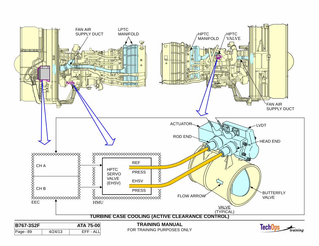
TRAINING MANUALFOR TRAINING PURPOSES ONLY
B767-3S2F ATA 75-00 Page - 89 4/24/13 EFF - ALL
TURBINE CASE COOLING (ACTIVE CLEARANCE CONTROL)
MANIFOLDLPTC
SUPPLY DUCTFAN AIR
EHSV
PRESS
PRESS
REF
HMU
CH B
CH A
EECVALVE
FLOW ARROW VALVEBUTTERFLY
HEAD ENDROD END
ACTUATOR LVDT
SERVOHPTC
(EHSV)VALVE
SUPPLY DUCTFAN AIR
VALVEHPTC
MANIFOLDHPTC
(TYPICAL)
TRAINING MANUALFOR TRAINING PURPOSES ONLY
B767-3S2F ATA 75-00 Page - 90 4/24/13 EFF - ALL
ENGINE AIR - INDICATIONS
General
Position indications show on the EPCS page for these engine air system components:
• Variable Stator Vane (VSV) actuators • Variable Bypass Valve (VBV) actuators • High Pressure Turbine Cooling (HPTC) valve
These parameter values show on the EPCS page for the temperatures and pressures for control of engine air system components:
• Ambient (static) pressure (P0) • HPC discharge (burner) static pressure (PS3) • HPC inlet temperature (T2.5) • HPC discharge (burner) temperature (T3)
The indications are in percent of maximum angle, with 0 percent equal to fully-closed positions and 100 percent equal to fully-open. The ranges for the indications are from -5.0 percent to 105.0 percent.
The P0 pressure indication range is from -1.5 to 20 PSIA, the PS3 indication range is from -5 to 600 PSIA, the T25 indication range is from 55 to 160C, and the T3 indication range is from -55 to 650C.
A box surrounds the EEC channel that is in control.
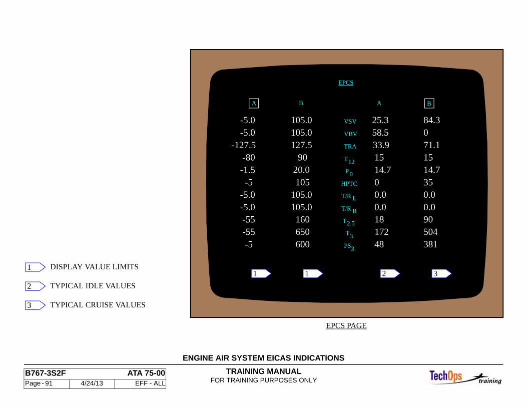
TRAINING MANUALFOR TRAINING PURPOSES ONLY
B767-3S2F ATA 75-00 Page - 91 4/24/13 EFF - ALL
ENGINE AIR SYSTEM EICAS INDICATIONS
PS3
3
381 600 48 -5 172
-5.0 -5.0
0.0 0.0
-55 -55 18
105.0105.0 160 90
0.0 0.0
650 504T
T/R
T/R L
R
T 2.5
EPCS
TRA
VBV
VSV
B BAA
105.0105.0127.5
84.3 0 71.1
25.3 58.5
33.9
-5.0 -5.0
-127.5
-5 -1.5 -80
0 14.7 15 15 90
105 35 14.7 20.0
HPTC
T12
0P
EPCS PAGE
1 2 311
2
3
DISPLAY VALUE LIMITS
TYPICAL IDLE VALUES
TYPICAL CRUISE VALUES
TRAINING MANUALFOR TRAINING PURPOSES ONLY
B767-3S2F ATA 75-00 Page - 92 4/24/13 EFF - ALL
ENGINE AIR - ENGINE AIR SYSTEM - OPERATION
Variable Stator Vanes
The VSVs move from fully closed during starting to fully open at takeoff power. The modulation schedule changes during reverse thrust operation. The VSVs fail-safe closed.
Variable Bypass Valves
The VBVs move from fully open during starting to fully closed at takeoff power. The modulation schedule changes during rapid deceleration and reverse thrust operation. The VBVs fail-safe open.
Core Compartment Cooling Valves
The CCCV is closed at stabilized cruise power when the aircraft is above 17,000 feet altitude and the EGT is less than 699C. Cooling airflow to engine accessories is reduced when the CCCV is closed. The CCCV is fail-safe open.
HPTC Valve
The HPTC valve opens at cruise power settings when the aircraft is above 17,000 feet altitude and N2 is between 82 percent and 98 percent. Turbine case cooling airflow is increased when the valve is open. The HPTC valve is fail-safe closed.
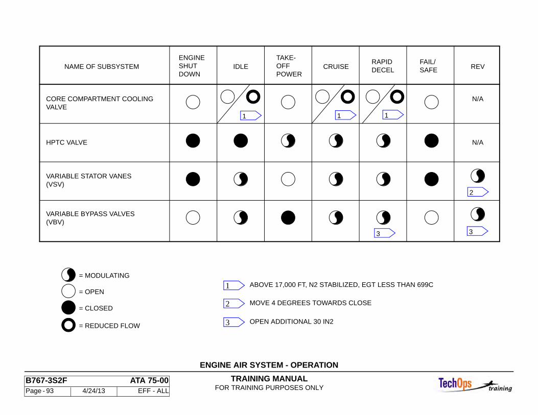
TRAINING MANUALFOR TRAINING PURPOSES ONLY
B767-3S2F ATA 75-00 Page - 93 4/24/13 EFF - ALL
ENGINE AIR SYSTEM - OPERATION
HPTC VALVE
REVSAFEFAIL/
DECELRAPID
CRUISEPOWER
TAKE-OFFIDLE
DOWNSHUTENGINE
NAME OF SUBSYSTEM
CORE COMPARTMENT COOLINGVALVE
(VSV)VARIABLE STATOR VANES
(VBV)VARIABLE BYPASS VALVES
N/A
N/A
OPEN ADDITIONAL 30 IN2
MOVE 4 DEGREES TOWARDS CLOSE
ABOVE 17,000 FT, N2 STABILIZED, EGT LESS THAN 699C= MODULATING
= OPEN
= CLOSED
= REDUCED FLOW
1
2
3
1
2
33
11
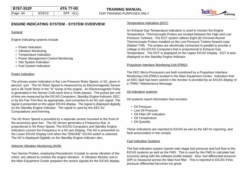
TRAINING MANUALFOR TRAINING PURPOSES ONLY
B767-3S2F ATA 77-00 Page - 94 4/24/13 EFF - ALL
ENGINE INDICATING SYSTEM - SYSTEM OVERVIEW
General
Engine indicating systems include
• Power Indication • Vibration Monitoring • Temperature Indication • Power Management Control Monitoring • Oils System Indication • Fuel System Indication
Power Indication
The primary power indication is the Low Pressure Rotor Speed, or N1, given in percent rpm. The N1 Rotor Speed is measured by an Electromagnetic Sensor and a 38 Tooth Rotor in the "A" Sump of the engine. An Electromagnetic Pulse is generated in the Sensor Coils each time a Tooth passes. The pulses per unit of time are measured by the EICAS Computers, Standby Engine Indicator, EEC, or by the Fan Trim Box as appropriate, and converted to an N1 rpm signal. The signal is presented on the upper EICAS display. The signal is displayed digitally on the Standby Engine Indicator. The signal is used by the EEC for Computations and trimming.
The N2 Rotor Speed is provided by a seperate sensor mounted to the front of the accessory gear box. The N2 sensor generates a Frequency that is proportional to N2 Rotor Speed. The EICAS Computers and Standby Engine Indicators convert the Frequency to a N2 rpm Display. The N2 is presented on the Lower EICAS Display Unit when the "ENGINE" EICAS switch is selected. The N2 is displayed Digitally on the Standby Engine Indicator also.
Airborne Vibration Monitoring (AVM)
Two Sensor Probes, employing Piezoelectric Crystals to sense vibration of the rotors, are utilized to monitor the engine vibration. A Vibration Monitor unit in the Main Equipment Center prepares the sensor signals for the EICAS display.
Temperature Indication (EGT)
An Exhaust Gas Temperature indication is used to monitor the Engine Temperature. Thermocouple Probes are located between the High and Low Pressure Turbines. The EGT system utilizes Eight (8) Chromel-Alumel Thermocouple Probes installed on the Low Pressure Turbine forward case (Station T49). The probes are electrically connected in parallel to provide a voltage to the EICAS Computers that is proportional to Exhaust Gas Temperature. The EGT is displayed on the Upper EICAS Display. EGT is also displayed on the Standby Engine Indicator.
Propulsion Interface Monitoring Unit (PIMU)
The EEC Micro-Processors are both monitored by a Propulsion Interface Monitoring Unit (PIMU) located in the Main Equipment Center. Indication that an EEC fault has been stored in the monitor is provided by an EICAS display ofa "PIMU" Maintenance Message.
Oil Indication systems
Oil systems report information that includes:
• Oil Pressure • Low Oil Pressure • Oil Filter DP Indication • Oil Temperature • Oil Quantity
These indications are reported to EICAS as wel as the SEI for reporting, and fault annunciation in the cockpit.
Fuel Indication Systems
The fuel indication system reports inter-stage fuel pressure and fuel flow to the EICAS systems as well as the FMS. This is used by the FMS to calculate fuel economy along with the software profile loaded. Also, fuel differential pressure (DP) is measured across the Main fuel filter. This is reported to EICAS if this pressure differential becomes too great.
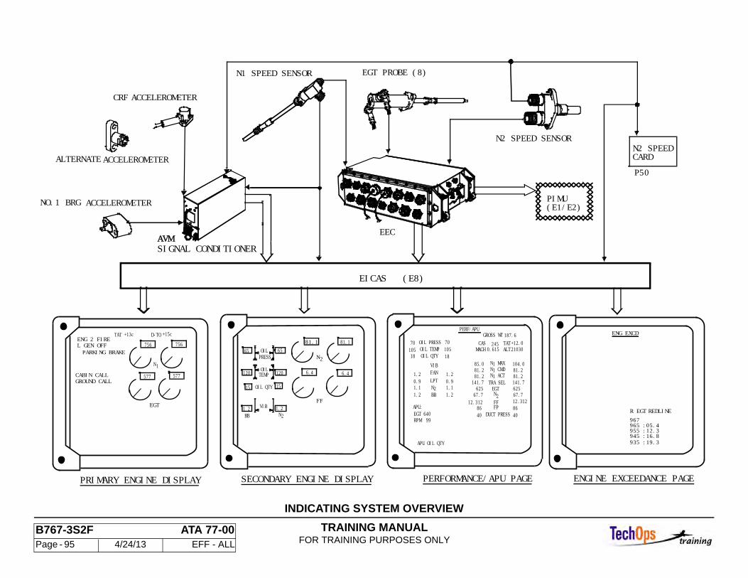
TRAINING MANUALFOR TRAINING PURPOSES ONLY
B767-3S2F ATA 77-00 Page - 95 4/24/13 EFF - ALL
VIBFF
PRESSOIL
TEMPOIL
OIL QTY
N2
120 120
1.2 1.2
15 15
65 6581.1
N
81.1
2
PARKING BRAKE
ENG 2 FIREL GEN OFF
CABIN CALLGROUND CALL
EGT
577 577
TAT +15cD-TO+13c
SECONDARY ENGINE DISPLAYPRIMARY ENGINE DISPLAY
REDLINE
:19.3935945955965
:16.8:12.3:05.4
R EGT967
ENGINE EXCEEDANCE PAGE
EEC
N1 SPEED SENSOR
N2 SPEED SENSOR
EGT PROBE (8)
N2 SPEEDCARD
PIMU(E1/E2)
P50
AVMSIGNAL CONDITIONER
CRF ACCELEROMETER
NO.1 BRG ACCELEROMETER
EICAS (E8)
ALTERNATE ACCELEROMETER
2
VIBFANLPTNBB
OIL QTYOIL TEMPOIL PRESS
104.081.281.2
81.2 81.2
62562567.767.7
8640
8640
12.31212.312
141.7141.7
85.0
DUCT PRESSFPFFN2EGT
TRA SELN ACT1N CMD1N MAX1
1.10.9
1.2
1.2
1.10.9
1.2
1.2
105 10518
70
18
7021030+12.0
187.6245
0.615 ALTTAT
GROSS WT
MACHCAS
PERFORMANCE/APU PAGE
ENG EXCDPERF/APU
APU:EGT 640RPM 99
APU OIL QTY
6.46.4
BB
756 756
N1
INDICATING SYSTEM OVERVIEW
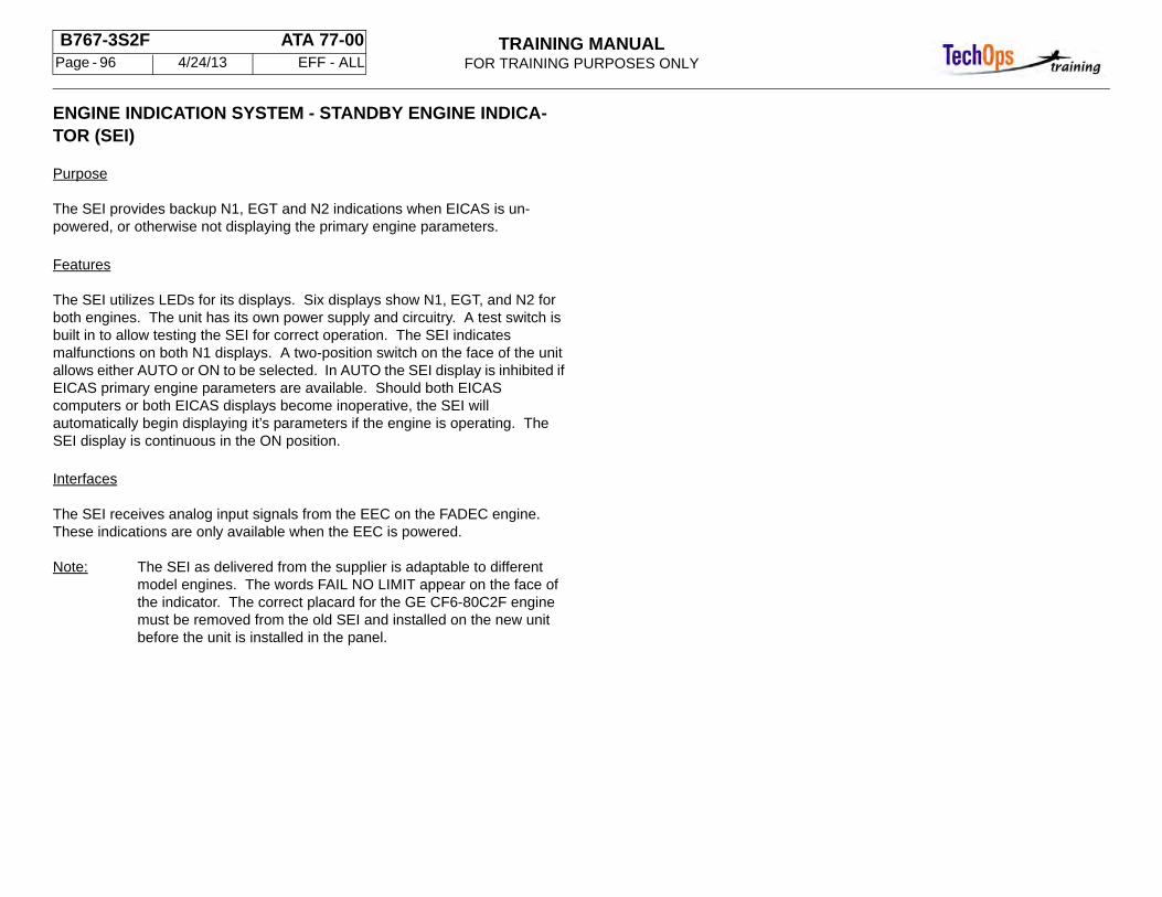
TRAINING MANUALFOR TRAINING PURPOSES ONLY
B767-3S2F ATA 77-00 Page - 96 4/24/13 EFF - ALL
ENGINE INDICATION SYSTEM - STANDBY ENGINE INDICA-TOR (SEI)
Purpose
The SEI provides backup N1, EGT and N2 indications when EICAS is un-powered, or otherwise not displaying the primary engine parameters.
Features
The SEI utilizes LEDs for its displays. Six displays show N1, EGT, and N2 for both engines. The unit has its own power supply and circuitry. A test switch is built in to allow testing the SEI for correct operation. The SEI indicates malfunctions on both N1 displays. A two-position switch on the face of the unit allows either AUTO or ON to be selected. In AUTO the SEI display is inhibited if EICAS primary engine parameters are available. Should both EICAS computers or both EICAS displays become inoperative, the SEI will automatically begin displaying it’s parameters if the engine is operating. The SEI display is continuous in the ON position.
Interfaces
The SEI receives analog input signals from the EEC on the FADEC engine. These indications are only available when the EEC is powered.
Note: The SEI as delivered from the supplier is adaptable to different model engines. The words FAIL NO LIMIT appear on the face of the indicator. The correct placard for the GE CF6-80C2F engine must be removed from the old SEI and installed on the new unit before the unit is installed in the panel.
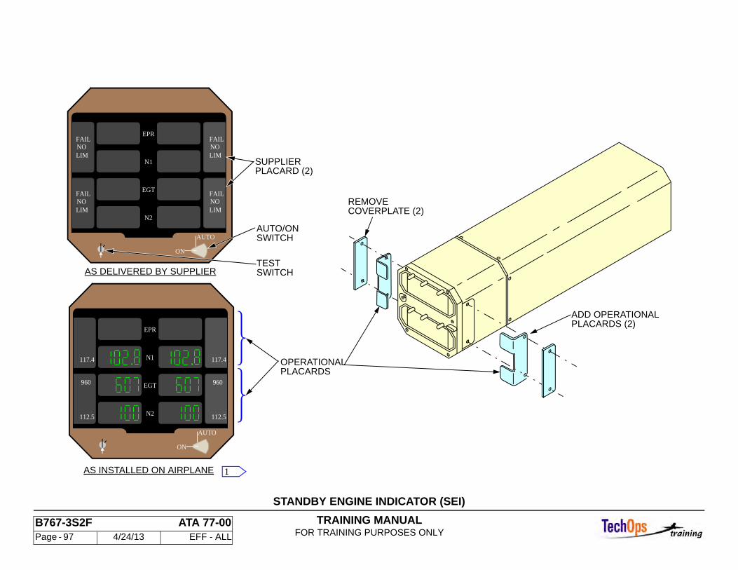
TRAINING MANUALFOR TRAINING PURPOSES ONLY
B767-3S2F ATA 77-00 Page - 97 4/24/13 EFF - ALL
STANDBY ENGINE INDICATOR (SEI)
EPR
ON
EGT
LIM
AUTO
N2
N1
FAILNO
LIM
FAILNO
LIM
FAILNO
LIM
FAILNO
AS DELIVERED BY SUPPLIER
OPERATIONALPLACARDS
COVERPLATE (2)REMOVE
PLACARDS (2)ADD OPERATIONAL
AS INSTALLED ON AIRPLANE
AUTO/ONSWITCH
TESTSWITCH
SUPPLIERPLACARD (2)
EPR
ON
EGT
117.4
AUTO
N2
N1
1
112.5
960
117.4
112.5
960
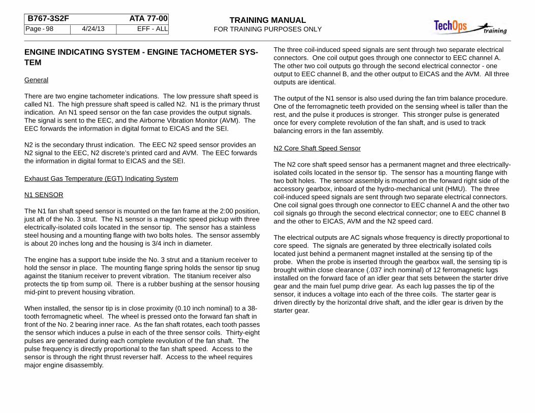
TRAINING MANUALFOR TRAINING PURPOSES ONLY
B767-3S2F ATA 77-00 Page - 98 4/24/13 EFF - ALL
ENGINE INDICATING SYSTEM - ENGINE TACHOMETER SYS-TEM
General
There are two engine tachometer indications. The low pressure shaft speed is called N1. The high pressure shaft speed is called N2. N1 is the primary thrust indication. An N1 speed sensor on the fan case provides the output signals. The signal is sent to the EEC, and the Airborne Vibration Monitor (AVM). The EEC forwards the information in digital format to EICAS and the SEI.
N2 is the secondary thrust indication. The EEC N2 speed sensor provides an N2 signal to the EEC, N2 discrete’s printed card and AVM. The EEC forwards the information in digital format to EICAS and the SEI.
Exhaust Gas Temperature (EGT) Indicating System
N1 SENSOR
The N1 fan shaft speed sensor is mounted on the fan frame at the 2:00 position, just aft of the No. 3 strut. The N1 sensor is a magnetic speed pickup with three electrically-isolated coils located in the sensor tip. The sensor has a stainless steel housing and a mounting flange with two bolts holes. The sensor assembly is about 20 inches long and the housing is 3/4 inch in diameter.
The engine has a support tube inside the No. 3 strut and a titanium receiver to hold the sensor in place. The mounting flange spring holds the sensor tip snug against the titanium receiver to prevent vibration. The titanium receiver also protects the tip from sump oil. There is a rubber bushing at the sensor housing mid-pint to prevent housing vibration.
When installed, the sensor tip is in close proximity (0.10 inch nominal) to a 38-tooth ferromagnetic wheel. The wheel is pressed onto the forward fan shaft in front of the No. 2 bearing inner race. As the fan shaft rotates, each tooth passes the sensor which induces a pulse in each of the three sensor coils. Thirty-eight pulses are generated during each complete revolution of the fan shaft. The pulse frequency is directly proportional to the fan shaft speed. Access to the sensor is through the right thrust reverser half. Access to the wheel requires major engine disassembly.
The three coil-induced speed signals are sent through two separate electrical connectors. One coil output goes through one connector to EEC channel A. The other two coil outputs go through the second electrical connector - one output to EEC channel B, and the other output to EICAS and the AVM. All three outputs are identical.
The output of the N1 sensor is also used during the fan trim balance procedure. One of the ferromagnetic teeth provided on the sensing wheel is taller than the rest, and the pulse it produces is stronger. This stronger pulse is generated once for every complete revolution of the fan shaft, and is used to track balancing errors in the fan assembly.
N2 Core Shaft Speed Sensor
The N2 core shaft speed sensor has a permanent magnet and three electrically-isolated coils located in the sensor tip. The sensor has a mounting flange with two bolt holes. The sensor assembly is mounted on the forward right side of the accessory gearbox, inboard of the hydro-mechanical unit (HMU). The three coil-induced speed signals are sent through two separate electrical connectors. One coil signal goes through one connector to EEC channel A and the other two coil signals go through the second electrical connector; one to EEC channel B and the other to EICAS, AVM and the N2 speed card.
The electrical outputs are AC signals whose frequency is directly proportional to core speed. The signals are generated by three electrically isolated coils located just behind a permanent magnet installed at the sensing tip of the probe. When the probe is inserted through the gearbox wall, the sensing tip is brought within close clearance (.037 inch nominal) of 12 ferromagnetic lugs installed on the forward face of an idler gear that sets between the starter drive gear and the main fuel pump drive gear. As each lug passes the tip of the sensor, it induces a voltage into each of the three coils. The starter gear is driven directly by the horizontal drive shaft, and the idler gear is driven by the starter gear.
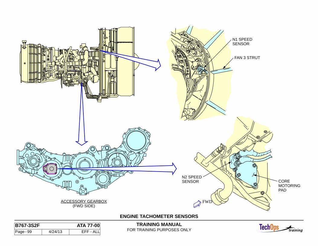
TRAINING MANUALFOR TRAINING PURPOSES ONLY
B767-3S2F ATA 77-00 Page - 99 4/24/13 EFF - ALL
ENGINE TACHOMETER SENSORS
MOTORINGCORE
PAD
SENSORN2 SPEED
N1 SPEEDSENSOR
FAN 3 STRUT
ACCESSORY GEARBOX(FWD SIDE)
FWD
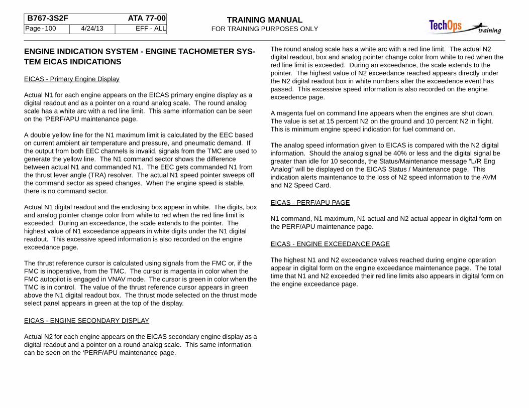
TRAINING MANUALFOR TRAINING PURPOSES ONLY
B767-3S2F ATA 77-00 Page - 100 4/24/13 EFF - ALL
ENGINE INDICATION SYSTEM - ENGINE TACHOMETER SYS-TEM EICAS INDICATIONS
EICAS - Primary Engine Display
Actual N1 for each engine appears on the EICAS primary engine display as a digital readout and as a pointer on a round analog scale. The round analog scale has a white arc with a red line limit. This same information can be seen on the ‘PERF/APU maintenance page.
A double yellow line for the N1 maximum limit is calculated by the EEC based on current ambient air temperature and pressure, and pneumatic demand. If the output from both EEC channels is invalid, signals from the TMC are used to generate the yellow line. The N1 command sector shows the difference between actual N1 and commanded N1. The EEC gets commanded N1 from the thrust lever angle (TRA) resolver. The actual N1 speed pointer sweeps off the command sector as speed changes. When the engine speed is stable, there is no command sector.
Actual N1 digital readout and the enclosing box appear in white. The digits, box and analog pointer change color from white to red when the red line limit is exceeded. During an exceedance, the scale extends to the pointer. The highest value of N1 exceedance appears in white digits under the N1 digital readout. This excessive speed information is also recorded on the engine exceedance page.
The thrust reference cursor is calculated using signals from the FMC or, if the FMC is inoperative, from the TMC. The cursor is magenta in color when the FMC autopilot is engaged in VNAV mode. The cursor is green in color when the TMC is in control. The value of the thrust reference cursor appears in green above the N1 digital readout box. The thrust mode selected on the thrust mode select panel appears in green at the top of the display.
EICAS - ENGINE SECONDARY DISPLAY
Actual N2 for each engine appears on the EICAS secondary engine display as a digital readout and a pointer on a round analog scale. This same information can be seen on the ‘PERF/APU maintenance page.
The round analog scale has a white arc with a red line limit. The actual N2 digital readout, box and analog pointer change color from white to red when the red line limit is exceeded. During an exceedance, the scale extends to the pointer. The highest value of N2 exceedance reached appears directly under the N2 digital readout box in white numbers after the exceedence event has passed. This excessive speed information is also recorded on the engine exceedence page.
A magenta fuel on command line appears when the engines are shut down. The value is set at 15 percent N2 on the ground and 10 percent N2 in flight. This is minimum engine speed indication for fuel command on.
The analog speed information given to EICAS is compared with the N2 digital information. Should the analog signal be 40% or less and the digital signal be greater than idle for 10 seconds, the Status/Maintenance message “L/R Eng Analog” will be displayed on the EICAS Status / Maintenance page. This indication alerts maintenance to the loss of N2 speed information to the AVM and N2 Speed Card.
EICAS - PERF/APU PAGE
N1 command, N1 maximum, N1 actual and N2 actual appear in digital form on the PERF/APU maintenance page.
EICAS - ENGINE EXCEEDANCE PAGE
The highest N1 and N2 exceedance valves reached during engine operation appear in digital form on the engine exceedance maintenance page. The total time that N1 and N2 exceeded their red line limits also appears in digital form on the engine exceedance page.
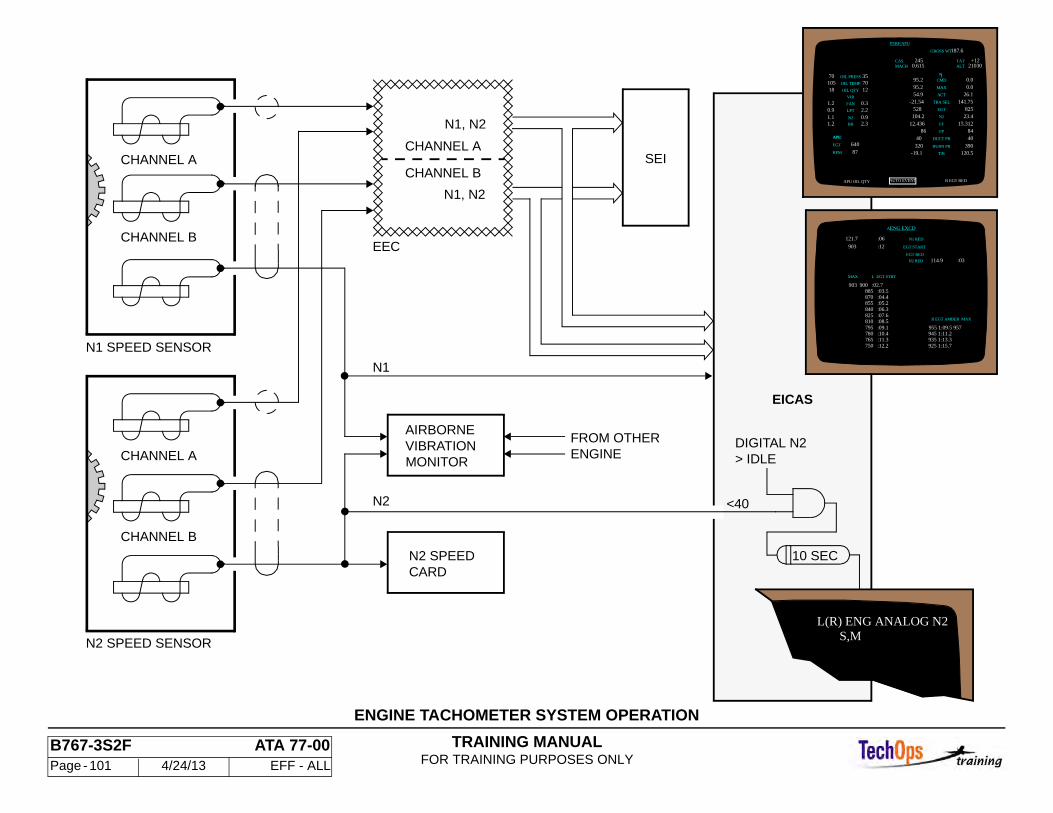
TRAINING MANUALFOR TRAINING PURPOSES ONLY
B767-3S2F ATA 77-00 Page - 101 4/24/13 EFF - ALL
ENGINE TACHOMETER SYSTEM OPERATION
N2
FROM OTHERENGINE > IDLE
DIGITAL N2
10 SEC
CHANNEL B
CHANNEL B
CHANNEL A
CHANNEL B
CHANNEL A
N1 SPEED SENSOR
N2 SPEED SENSOR
N1
N2 SPEEDCARD
EEC
N1, N2
N1, N2
CHANNEL ASEI
VIBRATIONAIRBORNE
MONITOR
EICAS
<40
S,ML(R) ENG ANALOG N2
903
903 900 :02.7
L EGT STRT
AENG EXCD
121.7
R EGT AMBER MAX
MAX
N2 RED
EGT RED
EGT START
N1 RED
:12
:06
:03
885 :03.5870 :04.4855 :05.2840 :06.3825 :07.6810 :08.5 795 :09.1780 :10.4765 :11.3750 :12.2 925 1:15.7
114.9
955 1:09.5 957945 1:11.2 935 1:13.3
PERF/APU
AUTO EVENT
0.3 VIB
BB1.2N2
1.2
2.30.9
LPT
1.1
35105 OIL TEMP
2.2FAN
0.9
70
12 70
OIL QTY
OIL PRESS
18
-19.1 T/R 120.5 320 390BURN PR
40DUCT PR 4084FP86
12.436 FF 15.312N2 23.4104.2
EGT 825-21.54 141.75 54.9 ACT 26.1
MAX 0.0 95.2
N 1
CAS
GROSS WT
R EGT RED
0.0 95.2
APU OIL QTY
187.6
CMD
21030 +12
ALTTAT
0.615 245
MACH
APU:
EGT 640
TRA SEL
RPM 87
528
APU:
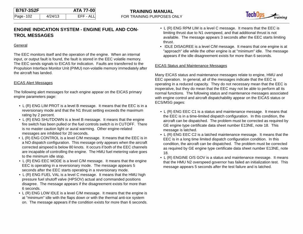
TRAINING MANUALFOR TRAINING PURPOSES ONLY
B767-3S2F ATA 77-00 Page - 102 4/24/13 EFF - ALL
ENGINE INDICATION SYSTEM - ENGINE FUEL AND CON-TROL MESSAGES
General
The EEC monitors itself and the operation of the engine. When an internal input, or output fault is found, the fault is stored in the EEC volatile memory. The EEC sends signals to EICAS for indication. Faults are transferred to the Propulsion Interface Monitor Unit (PIMU) non-volatile memory immediately after the aircraft has landed.
EICAS Alert Messages
The following alert messages for each engine appear on the EICAS primary engine parameters page:
• L (R) ENG LIM PROT is a level B message. It means that the EEC is in a reversionary mode and that the N1 thrust setting exceeds the maximum rating by 2 percent.
• L (R) ENG SHUTDOWN is a level B message. It means that the engine fire switch has been pulled or the fuel controls switch is in CUTOFF. There is no master caution light or aural warming. Other engine-related messages are inhibited for 20 seconds.
• L (R) ENG CONTROL is a level C/M message. It means that the EEC is in a NO dispatch configuration. This message only appears when the aircraft corrected airspeed is below 80 knots. It occurs if both of the EEC channels are incapable of controlling the engine. The HMU fuel metering valve goes to the minimum idle stop.
• L (R) ENG EEC MODE is a level C/M message. It means that the engine EEC is operating in a reversionary mode. The message appears 5 seconds after the EEC starts operating in a reversionary mode.
• L (R) ENG FUEL VAL is a level C message. It means that the HMU high pressure fuel shutoff valve (HPSOV) actual and commanded positions disagree. The message appears if the disagreement exists for more than 6 seconds.
• L (R) ENG LOW IDLE is a level C/M message. It means that the engine is at "minimum" idle with the flaps down or with the thermal anti-ice system on. The message appears if the condition exists for more than 6 seconds.
• L (R) ENG RPM LIM is a level C message. It means that the EEC is limiting thrust due to N1 overspeed, and that additional thrust is not available. The message appears 3 seconds after the EEC starts limiting thrust.
• IDLE DISAGREE is a level C/M message. It means that one engine is at "approach" idle while the other engine is at "minimum" idle. The message appears if the idle disagreement exists for more than 6 seconds.
EICAS Status and Maintenance Messages
Many EICAS status and maintenance messages relate to engine, HMU and EEC operation. In general, all of the messages indicate that the EEC is operating in a reduced capacity. They do not necessary mean that the EEC is inoperative, but they do mean that the EEC may not be able to perform all its normal functions. The following status and maintenance messages associated with engine control and aircraft dispatchability appear on the EICAS status or ECS/MSG pages:
• L (R) ENG EEC C1 is a status and maintenance message. It means that the EEC is in a time-limited dispatch configuration. In this condition, the aircraft can be dispatched. The problem must be corrected as required by GE engine type certificate data sheet number E13NE, note 18. This message is latched.
• L (R) ENG EEC C2 is a latched maintenance message. It means that the EEC is in a long time limited dispatch configuration condition. In this condition, the aircraft can be dispatched. The problem must be corrected as required by GE engine type certificate data sheet number E13NE, note 18.
• L (R) ENGINE O/S GOV is a status and maintenance message. It means that the HMU N2 overspeed governor has failed an initialization test. This message appears 5 seconds after the test failure and is latched.
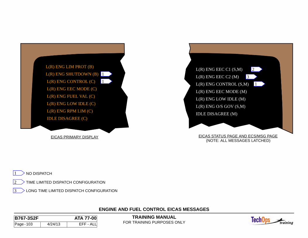
TRAINING MANUALFOR TRAINING PURPOSES ONLY
B767-3S2F ATA 77-00 Page - 103 4/24/13 EFF - ALL
ENGINE AND FUEL CONTROL EICAS MESSAGES
L(R) ENG EEC C2 (M)
L(R) ENG CONTROL (S,M)
L(R) ENG EEC MODE (M)
L(R) ENG LOW IDLE (M)
IDLE DISAGREE (M)
L(R) ENG O/S GOV (S,M)
(NOTE: ALL MESSAGES LATCHED)EICAS STATUS PAGE AND ECS/MSG PAGE
LONG TIME LIMITED DISPATCH CONFIGURATION
TIME LIMITED DISPATCH CONFIGURATION
IDLE DISAGREE (C)
L(R) ENG RPM LIM (C)
L(R) ENG LOW IDLE (C)
L(R) ENG FUEL VAL (C)
L(R) ENG EEC MODE (C)
L(R) ENG CONTROL (C)
L(R) ENG SHUTDOWN (B)
NO DISPATCH
EICAS PRIMARY DISPLAY
L(R) ENG LIM PROT (B)L(R) ENG EEC C1 (S,M)
1
11
3
2
1
2
3
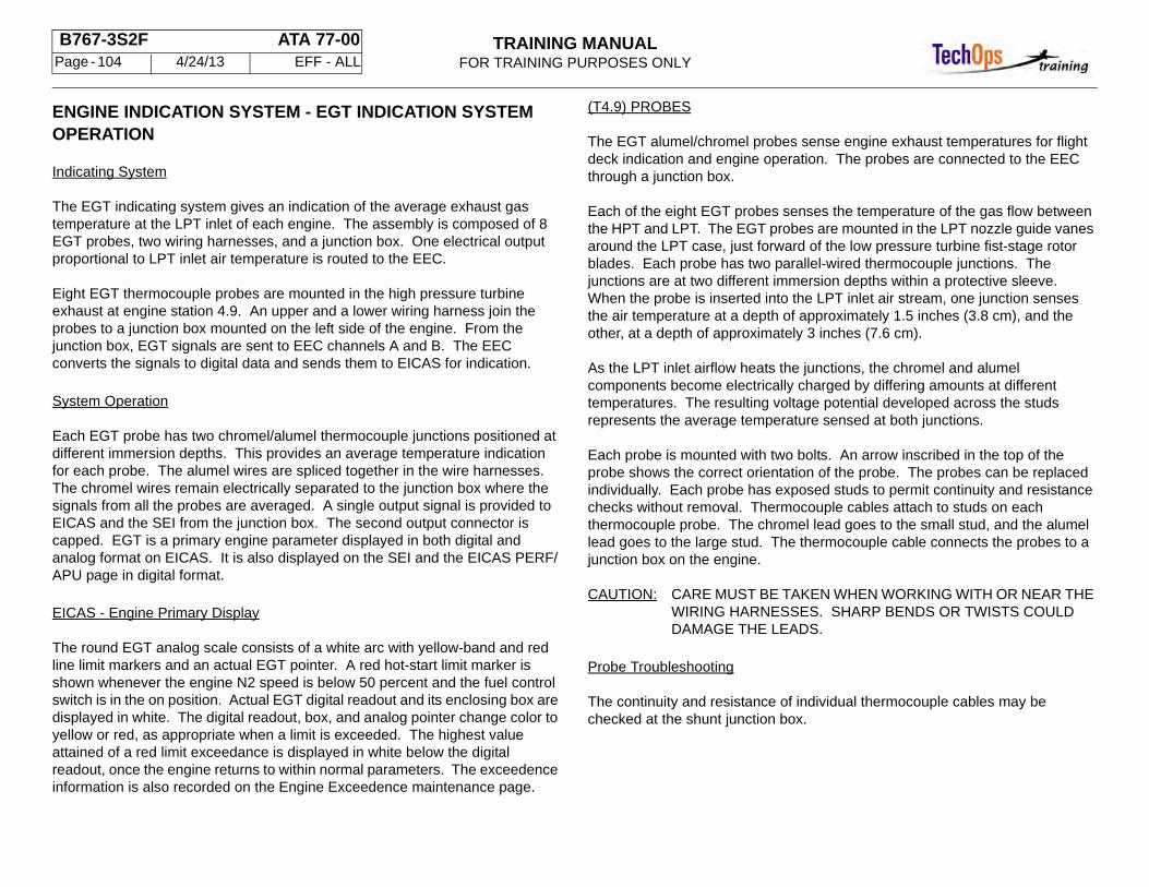
TRAINING MANUALFOR TRAINING PURPOSES ONLY
B767-3S2F ATA 77-00 Page - 104 4/24/13 EFF - ALL
ENGINE INDICATION SYSTEM - EGT INDICATION SYSTEM OPERATION
Indicating System
The EGT indicating system gives an indication of the average exhaust gas temperature at the LPT inlet of each engine. The assembly is composed of 8 EGT probes, two wiring harnesses, and a junction box. One electrical output proportional to LPT inlet air temperature is routed to the EEC.
Eight EGT thermocouple probes are mounted in the high pressure turbine exhaust at engine station 4.9. An upper and a lower wiring harness join the probes to a junction box mounted on the left side of the engine. From the junction box, EGT signals are sent to EEC channels A and B. The EEC converts the signals to digital data and sends them to EICAS for indication.
System Operation
Each EGT probe has two chromel/alumel thermocouple junctions positioned at different immersion depths. This provides an average temperature indication for each probe. The alumel wires are spliced together in the wire harnesses. The chromel wires remain electrically separated to the junction box where the signals from all the probes are averaged. A single output signal is provided to EICAS and the SEI from the junction box. The second output connector is capped. EGT is a primary engine parameter displayed in both digital and analog format on EICAS. It is also displayed on the SEI and the EICAS PERF/APU page in digital format.
EICAS - Engine Primary Display
The round EGT analog scale consists of a white arc with yellow-band and red line limit markers and an actual EGT pointer. A red hot-start limit marker is shown whenever the engine N2 speed is below 50 percent and the fuel control switch is in the on position. Actual EGT digital readout and its enclosing box are displayed in white. The digital readout, box, and analog pointer change color to yellow or red, as appropriate when a limit is exceeded. The highest value attained of a red limit exceedance is displayed in white below the digital readout, once the engine returns to within normal parameters. The exceedence information is also recorded on the Engine Exceedence maintenance page.
(T4.9) PROBES
The EGT alumel/chromel probes sense engine exhaust temperatures for flight deck indication and engine operation. The probes are connected to the EEC through a junction box.
Each of the eight EGT probes senses the temperature of the gas flow between the HPT and LPT. The EGT probes are mounted in the LPT nozzle guide vanes around the LPT case, just forward of the low pressure turbine fist-stage rotor blades. Each probe has two parallel-wired thermocouple junctions. The junctions are at two different immersion depths within a protective sleeve. When the probe is inserted into the LPT inlet air stream, one junction senses the air temperature at a depth of approximately 1.5 inches (3.8 cm), and the other, at a depth of approximately 3 inches (7.6 cm).
As the LPT inlet airflow heats the junctions, the chromel and alumel components become electrically charged by differing amounts at different temperatures. The resulting voltage potential developed across the studs represents the average temperature sensed at both junctions.
Each probe is mounted with two bolts. An arrow inscribed in the top of the probe shows the correct orientation of the probe. The probes can be replaced individually. Each probe has exposed studs to permit continuity and resistance checks without removal. Thermocouple cables attach to studs on each thermocouple probe. The chromel lead goes to the small stud, and the alumel lead goes to the large stud. The thermocouple cable connects the probes to a junction box on the engine.
CAUTION: CARE MUST BE TAKEN WHEN WORKING WITH OR NEAR THE WIRING HARNESSES. SHARP BENDS OR TWISTS COULD DAMAGE THE LEADS.
Probe Troubleshooting
The continuity and resistance of individual thermocouple cables may be checked at the shunt junction box.
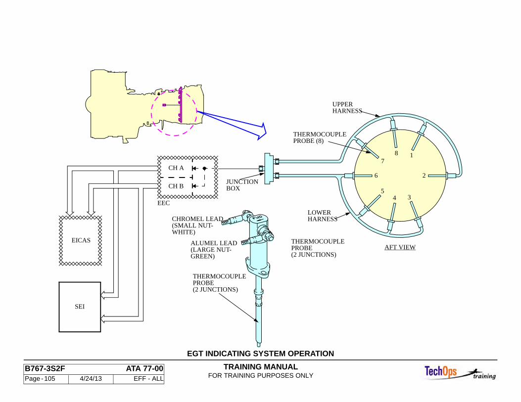
TRAINING MANUALFOR TRAINING PURPOSES ONLY
B767-3S2F ATA 77-00 Page - 105 4/24/13 EFF - ALL
EGT INDICATING SYSTEM OPERATION
CH B
CH A
SEI
EEC
EICASAFT VIEW
JUNCTIONBOX
LOWERHARNESS
PROBE (8)THERMOCOUPLE
UPPERHARNESS
5
6
71
2
3
8
4
THERMOCOUPLE
(2 JUNCTIONS)PROBE
(SMALL NUT-WHITE)
CHROMEL LEAD
ALUMEL LEAD
GREEN)(LARGE NUT-
THERMOCOUPLE
(2 JUNCTIONS)PROBE
TRAINING MANUALFOR TRAINING PURPOSES ONLY
B767-3S2F ATA 77-00 Page - 106 4/24/13 EFF - ALL
ENGINE INDICATION SYSTEM - AIRBORNE VIBRATION MON-ITORING SYSTEM
General
The airborne vibration monitoring (AVM) system continuously monitors engine vibrations to detect malfunctions. The system has two accelerometers mounted on each engine, and an AVM signal conditioner located on the E2-4 rack in the main equipment center. Vibration indications are shown on EICAS.
Accelerometers
The No. 1 bearing accelerometer and compressor rear frame (CRF) accelerometer sense vibrations caused by rotation imbalances of the N1 and N2 systems (shafts, blades, rotors, etc.) using piezo crystals. The crystals produce an electric charge proportional to engine vibrations. The charge signals from both accelerometers go to the AVM signal conditioner over shielded wire leads.
AVM Signal Conditioner
Four signals are sent from each engine to the AVM signal conditioner. They are:
• Fan vibration signals from the No. 1 bearing accelerometer. • Core vibration signals from the CRF accelerometer. • N1 speed signal from the N1 speed sensor. • N2 speed signal from the N2 speed sensor.
The AVM signal conditioner uses the accelerometer and speed signals to determine vibration velocity and displacement data for each airplane. The vibration data is sent to EICAS on an ARINC 429 digital bus. Data sent by the signal conditioner to EICAS can also be used for fan trim balancing.
The AVM signal conditioner has four cable connectors -- three on the back (not shown) and one on the front panel. The connector on the front panel is a 24-pin bayonet connector with protective cover. Maintenance operations are performed using the front panel connector; the signal conditioner has no additional test switches, status LEDs or fault readout displays.
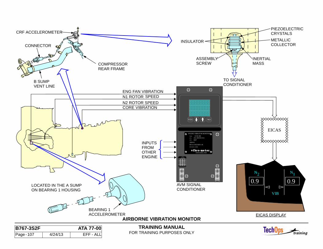
TRAINING MANUALFOR TRAINING PURPOSES ONLY
B767-3S2F ATA 77-00 Page - 107 4/24/13 EFF - ALL
AIRBORNE VIBRATION MONITOR
N2 ROTOR SPEED
AVM SIGNALCONDITIONER
VIB
0.90.9
N2 N1
EICAS DISPLAY
ENG FAN VIBRATION
CORE VIBRATION
BEARING 1ACCELEROMETER
LOCATED IN THE A SUMPON BEARING 1 HOUSING
B SUMPVENT LINE
CONNECTOR
COMPRESSORREAR FRAME
N1 ROTOR SPEED
INPUTS
ENGINE
FROMOTHER
METALLICCOLLECTOR
INERTIALMASS
TO SIGNALCONDITIONER
SCREWASSEMBLY
CRYSTALSPIEZOELECTRIC
INSULATOR
CRF ACCELEROMETER
EICAS
20
19
18
17
16
15
14
13
12
11
10
9
8
7
6
5
4
3
2
1
YES NO
RECORDMOD
SWITZERLAND
FSCM No: S3960
BO no S362A001-1R
2000-01
0007S/N:
241-280-001-011P/N:
EVM 280Type:
ENGINE VIBRATOR MONITOR
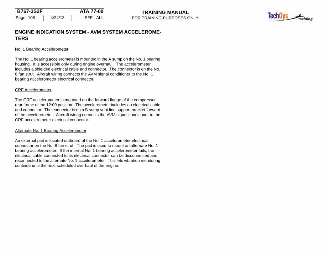
TRAINING MANUALFOR TRAINING PURPOSES ONLY
B767-3S2F ATA 77-00 Page - 108 4/24/13 EFF - ALL
ENGINE INDICATION SYSTEM - AVM SYSTEM ACCELEROME-TERS
No. 1 Bearing Accelerometer
The No. 1 bearing accelerometer is mounted in the A sump on the No. 1 bearing housing. It is accessible only during engine overhaul. The accelerometer includes a shielded electrical cable and connector. The connector is on the No. 8 fan strut. Aircraft wiring connects the AVM signal conditioner to the No. 1 bearing accelerometer electrical connector.
CRF Accelerometer
The CRF accelerometer is mounted on the forward flange of the compressor rear frame at the 12:00 position. The accelerometer includes an electrical cable and connector. The connector is on a B sump vent line support bracket forward of the accelerometer. Aircraft wiring connects the AVM signal conditioner to the CRF accelerometer electrical connector.
Alternate No. 1 Bearing Accelerometer
An external pad is located outboard of the No. 1 accelerometer electrical connector on the No. 8 fan strut. The pad is used to mount an alternate No. 1 bearing accelerometer. If the internal No. 1 bearing accelerometer fails, the electrical cable connected to its electrical connector can be disconnected and reconnected to the alternate No. 1 accelerometer. This lets vibration monitoring continue until the next scheduled overhaul of the engine.
TRAINING MANUALFOR TRAINING PURPOSES ONLY
B767-3S2F ATA 77-00 Page - 109 4/24/13 EFF - ALL
AVM SYSTEM ACCELEROMETERS
(REF)
FAN STRUT
FWD
CONNECTOR (REF)
NO. 8
BEARING ACCELEROMETERALTERNATE NO. 1
ELECTRICALCONNECTOR
ACCELEROMETERNO. 1 BEARINGALTERNATE
ELECTRICALACCELEROMETERNO. 1 BEARING
PT 2.5PROBE
ALTERNATEMOUNTING PAD
TRAINING MANUALFOR TRAINING PURPOSES ONLY
B767-3S2F ATA 77-00 Page - 110 4/24/13 EFF - ALL
ENGINE INDICATION SYSTEM - AVM SYSTEM INDICATIONS
General
Engine vibration data appears on the EICAS secondary engine display directly below the oil quantity indications. The indications consist of a vibration mode call out, and the vibration value using both a digital readout and a vertical analog pointer. The vibration data also appears on the PERF/APU page.
Vibration Mode
A white FAN, LPT, N2 or BB call out appears above the actual readout to identify the source of the highest vibration.
Vibration Data
A digital indication of engine vibration appears as a white number enclosed in a white box next to the vertical scale. The readout indicates engine vibration in the unit less range 0 to 5. A white triangular pointer on the inside of a vertical scale also indicates engine vibration level. There are two digital and vertical scale indications, one for each engine.
PERF/APU Page
The FAN, LPT, N2 and BB vibration levels are all shown on the PERF/APU page.

TRAINING MANUALFOR TRAINING PURPOSES ONLY
B767-3S2F ATA 77-00 Page - 111 4/24/13 EFF - ALL
AVM SYSTEM INDICATION
2.3
BB
SECONDARY ENGINE DISPLAY PERF/APU PAGE
OIL PRESS
TEMP
OIL QTY
VIB
105
18 12
70
N
35
70OIL
12.4
93
3.1
FAN
FF
2
93
12.4
2.03.1
VIB
N1
FAN
N2
BB1.2 FAN PH
LPT PH
180 90
AUTO EVENT
-19.1 T/R 120.5 320 390BURN PR
40DUCT PR 4084FP86
12.436 FF 15.312N2 23.4104.2
EGT 825 528-21.54 141.75
54.9 ACT 26.1MAX 0.0 95.2
N 1
CAS
GROSS WT
R EGT RED
0.0 95.2
APU OIL QTY
187.6
CMD
21030 +12
ALTTAT
0.615 245
MACH
TRA SEL
PERF/APU
35105 70
12 70
18OIL TEMP
OIL QTY
OIL PRESS
0.3
0.91.10.9
2.3
45 90
640
87
EGT
RPM
APU:
TRAINING MANUALFOR TRAINING PURPOSES ONLY
B767-3S2F ATA 77-00 Page - 112 4/24/13 EFF - ALL
ENGINE INDICATION SYSTEM - ENGINE N2 SPEED CARDS
Purpose
The engine N2 speed cards interface between the control alternators (N2 speed sensor) and other airplane systems to provide an N2 speed signal as required. Two cards, one for each engine, are located in the P50 card file in the main equipment center.
Characteristics
The cards are a printed circuit type. They each have two channels. There is a toggle-type test switch for each channel. Channel 1 has a non-momentary switch. Channel 2 has a momentary switch. Comparators control relays within the card to send speed signals to user systems.
WARNING: MOVING ENGINE N2 DISCRETE PRINTED CIRCUIT CARD CH. 1 SWITCH TO TEST CAUSES PROBE HEAT POWER TO BE APPLIED. PHYSICAL CONTACT WITH PROBE BODY CAN CAUSE SEVERE BURNS.
CAUTION: MOVING ENGINE N2 DISCRETE PRINTED CIRCUIT CARD CH. 1 SWITCH TO TEST CAUSES PROBE HEAT POWER TO BE APPLIED. BE SURE ANY PROTECTIVE COVERS AND TEST EQUIPMENT IS CLEAR OF PROBE BODY. HIGH PROBE TEMPERATURES MAY DAMAGE EQUIPMENT.
CAUTION: STATIC SENSITIVE. DO NOT HANDLE BEFORE READING PROCEDURE FOR HANDLING ELECTROSTATIC DISCHARGE SENSITIVE DEVICES. CONTAINS DEVICES THAT CAN BE DAMAGED BY STATIC DISCHARGES.
Operation
Each N2 speed card channel gets power from the 28vdc battery bus. Each channel gets the N2 core shaft speed sensor output signal. The signal is converted to a speed value by the N2 speed card sensing logic. The N2 speed value is compared to set values by four comparators. When the N2 speed value is determined to be above a fixed comparator value, N2 speed card relays are energized. The relay states permit user systems to determine if the N2 speed is above or below set values.
If the channel 1, 50% comparator, disagrees with the channel 2, 52% comparator, for more than 10 seconds, the EICAS status and maintenance message L(R) ENG SPEED CARD appears. This is a latched message. The message is inhibited when the standby bus does not have power.
Displays and Indications
If the two channels of a card disagree on sensed 50% speed for more than 10 seconds, a L(R) ENG SPEED CARD message appears on the EICAS status page and ECS/MSG page. The message is latched, and is inhibited by the STBY BUS OFF message.

TRAINING MANUALFOR TRAINING PURPOSES ONLY
B767-3S2F ATA 77-00 Page - 113 4/24/13 EFF - ALL
CARD FRONTEDGE
A
BB
A
ENGINE N2 SPEED CARD (P50)
OVERRIDE PUMP SHUT DOWN
EEC ALTN LIGHT INHIBIT
N2 SPEEDSENSOR
52/49%
50/47%COMPARATOR
50/47%COMPARATOR
COMPARATOR
28V DCBAT BUS
SENSEENG SPEED
28V DCBAT BUS
SENSEENG SPEED
P11
POWERSUPPLY
N2 SENSING
TEST
NORM
CHANNEL 2CHANNEL 1
PITOT/STATIC PROBE HEATENG START SW RELAY
POWERSUPPLY
TEST
NORM
COMPARATOR83/72%
EQUIPMENT COOLING
RAT EXTENSION
ECS HI FLOW INHIBIT
LOAD SHED (GND SVC BUS)
AOA PROBE HEAT
STARTER CUTOUT MESSAGE
10 SEC
STBY BUS ON
L(R) ENG N2 SPEED CARD "SM"
STATUS AND MAINT MSG PAGES
OPEN = FAULTGND = NORMAL
N2 SENSING
NORMAL
NORMAL
TEST
TEST
CH 2
CH 1
MOMENTARY
NON-MOMENTARY
NVM
1
1
EITHER ENGINE N2 < 50% (AIRBORNE ONLY) (K9)BUS WHEN THE R UTILITY BUS IS UNPOWERED AND(OPTIONAL) SHEDS A PORTION OF THE GROUND SERVICE
AND IS ON SUCTION FLOWA
ILLUMINATES THE RESPECTIVE ENGINE START VALVE
(K6)PACK WITH EITHER ENGINE N2 < 50% (AIRBORNE ONLY)
DC PUMP WHEN AIRBORNE WHEN L ENGINES N2 < 72%
UNTIL THE L ENGINE N2 > 83%
72%
83%
OPERATE WITH N2 > 52% (K5)
(K7)PROBE ON THE GROUND WITH EITHER ENGINE N2 > 50%
WITH EITHER ENGINE N2 < 50% (K7)
ABOVE 80 KNOTS WITH BOTH ENGINES N2 < 50% (K8)
(K6)COOLING ON THE GROUND WITH BOTH ENGINES N2 > 50%
RELAY WHEN N2 > 50% (K1)
THE GROUND WHEN EITHER ENGINE N2 > 50% (K2)
50%
RESPECTIVE ENGINE N2 < 50% (K4)
ENGINE N2 < 50% (K-2)
1
A
B
CHAN
2
SHUTS OFF THE OVERRIDE PUMP WHEN THE RESPECTIVE
NO.
ENERGIZING THE START SWITCH SOLENOID AND START
OPENS THE APU ISOLATION VALVE AND STARTS THE
AMBER LIGHT WHEN THE STARTER CONTINUES TO
INHIBITS ANGLE-OF-ATTACK PROBE HEAT ON THE GROUND
2
2
2
2
2
80-11
30-33
30-32
30-31
29-00
21-58
21-51
24-51
52%
50%
50%
50%
50%
50%
E
D
D
D
D
D
PROVIDES "INBOARD OPEN LOOP" FOR EQUIPMENT
INHIBITS THE AMBER LIGHT FOR THE TOTAL AIR TEMP
PROVIDES LOW HEAT MODE ON PITOT-STATIC PROBES ON
EXTENDS THE RAM-AIR-TURBINE (RAT) WHEN AIRBORNE
INHIBITS HIGH FLOW SCHEDULE FOR OPPOSITE COOLING
50%
50%
50%
50%
2
1
1
1
1
1
CHAPTER-
80-11
73-21
28-22
28-25
28-25
D
B
B
C CLOSES RESPECTIVE ENGINE START VALVE BY DE-
INHIBITS THE "EEC INOP" AMBER LIGHT WITH THE
ISOLATION VALVE OPEN AND DC PUMP OPERATINGM1093 L ENG SPEED CARD ONLY. RETAINS THE APU
PURPOSEREFN2SUBJECT
TABLE - SPEED CARD DISCRETES
EICAS
ENGINE N2 SPEED CARDS

TRAINING MANUALFOR TRAINING PURPOSES ONLY
B767-3S2F ATA 77-00 Page - 114 4/24/13 EFF - ALL
ENGINE INDICATION SYSTEM - CONDITION MONITORING
General
The condition monitoring system includes three pressure probes and one temperature sensor which send analog signals to the EEC. The EEC converts the converts the analog signal to digital data and sends a multiplexed signal to the PIMU. The ARINC communications and reporting system (ACARS) uses this information for diagnosis and fault information.
The condition monitoring system includes signals from the following engine mounted sensors:
• PS14 Fan Discharge Pressure • P4.9 LPT Inlet Pressure • T5 LPT Discharge Temperature • P2.5 Compressor Inlet Pressure
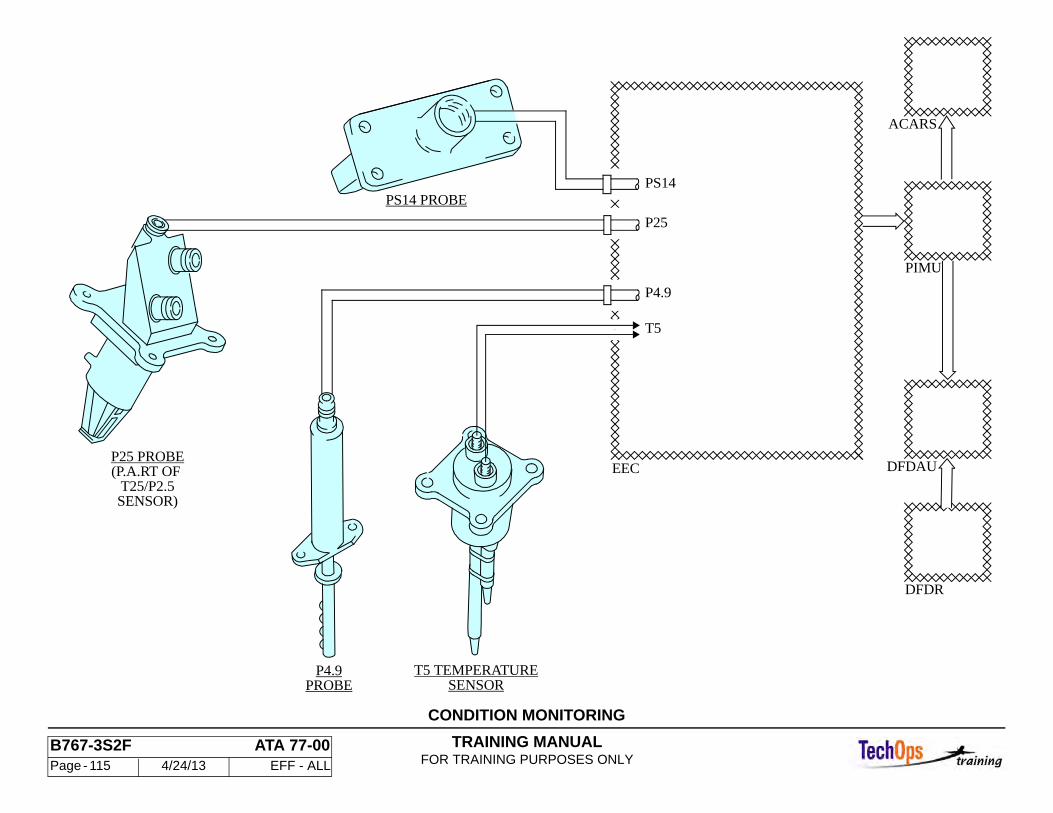
TRAINING MANUALFOR TRAINING PURPOSES ONLY
B767-3S2F ATA 77-00 Page - 115 4/24/13 EFF - ALL
CONDITION MONITORING
P4.9
P25
PS14
T5
EEC
PS14 PROBE
T25/P2.5
P25 PROBE(P.A.RT OF
SENSOR)
T5 TEMPERATUREPROBE
P4.9SENSOR
DFDAU
PIMU
DFDR
ACARS
TRAINING MANUALFOR TRAINING PURPOSES ONLY
B767-3S2F ATA 77-00 Page - 116 4/24/13 EFF - ALL
ENGINE INDICATION SYSTEM - PROPULSION INTERFACE MONITOR UNIT (PIMU) SYSTEM
The Propulsion Interface Monitor Unit (PIMU) collects and stores fault information from the EEC. There are two PIMUs, one for each engine, located in the main equipment center. The left engine PIMU is in the E1-3 rack and the right engine PIMU is in the E2-4 rack.
The 115vac ground service bus supplies power to the unit. Engine operating data is sent by both EEC channels. The unit accepts fault data from the EEC for 5 seconds after the airplane has landed and the air/ground relay has switched to the ground position. The monitor unit has a nonvolatile memory to store the data. The EICAS maintenance message "L(R) PIMU" appears if a fault is stored. The interface between the EEC and the aircraft components operate automatically. When the PIMU is interrogated, fault messages are shown on the face of the monitor unit. The PIMU interface buffer sends the data to the digital flight data acquisition unit (DFDAU) and the thrust management computer (TMC).
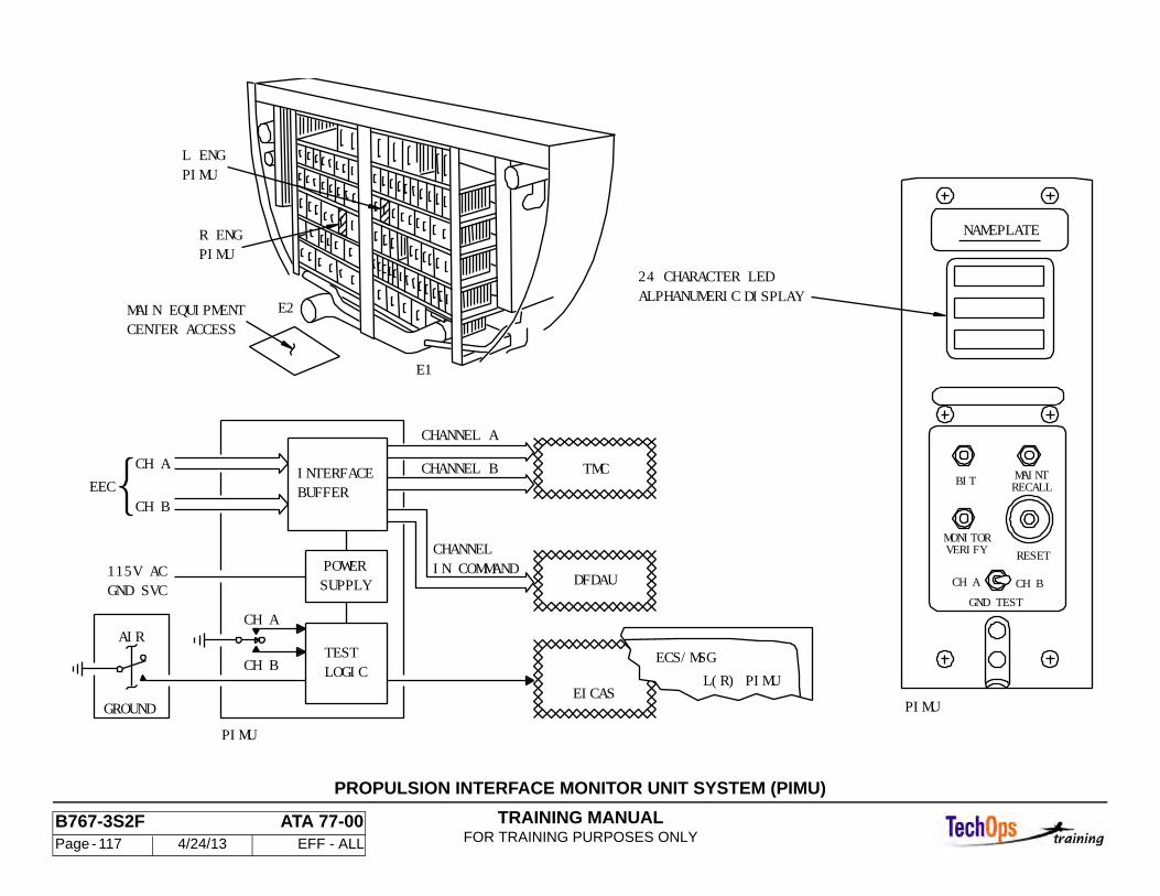
TRAINING MANUALFOR TRAINING PURPOSES ONLY
B767-3S2F ATA 77-00 Page - 117 4/24/13 EFF - ALL
BUFFERINTERFACE
GROUNDPIMU
CH AEEC
CH B
GND SVC115V AC
AIR
DFDAU
TMC
POWERSUPPLY
TESTLOGIC
PIMUL ENG
PIMUR ENG
E1
MAIN EQUIPMENTCENTER ACCESS
E2
24 CHARACTER LEDALPHANUMERIC DISPLAY
NAMEPLATE
CH BCH A
RECALLMAINT
GND TEST
RESETVERIFYMONITOR
BIT
PIMU
IN COMMANDCHANNEL
CHANNEL B
CHANNEL A
CH A
CH BL(R) PIMU
EICAS
ECS/MSG
PROPULSION INTERFACE MONITOR UNIT SYSTEM (PIMU)
TRAINING MANUALFOR TRAINING PURPOSES ONLY
B767-3S2F ATA 77-00 Page - 118 4/24/13 EFF - ALL
ENGINE INDICATION SYSTEM - AUTOMATIC FAULT RECORDING DURING FLIGHT OPERATIONS
General
PIMU automatic fault recording occurs when the Air / Ground relay system signals that the airplane has landed. For a period of 5 seconds, the PIMU records in non-volatile memory (NVM) any faults being sent over the channel A and B data busses from the EEC.
The flight is not finished at the time of landing. Thrust reverse, taxi and engine shutdown operations are yet to happen. The EEC will continue to monitor the system for faults. Any faults will be held in the EEC buffer until the N2 speed decreases below 20% on engine shutdown.
Faults detected by the EEC after touchdown will not be stored by the PIMU. The only way to determine if faults were stored in the EEC NVM after landing is to perform the PIMU maintenance recall procedures. Unless there was an EICAS message that was not appropriate for the results of a normal PIMU BITE procedure, there would not be any indication that hidden faults exist in EEC memory.
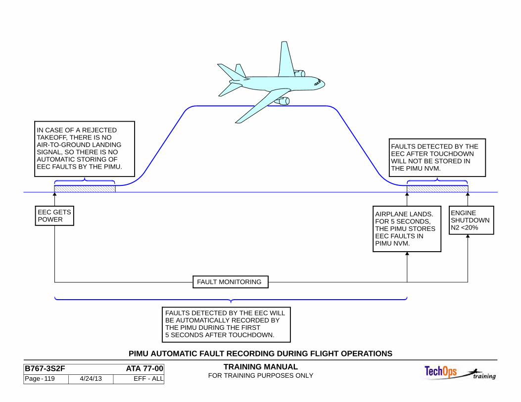
TRAINING MANUALFOR TRAINING PURPOSES ONLY
B767-3S2F ATA 77-00 Page - 119 4/24/13 EFF - ALL
PIMU AUTOMATIC FAULT RECORDING DURING FLIGHT OPERATIONS
5 SECONDS AFTER TOUCHDOWN.THE PIMU DURING THE FIRSTBE AUTOMATICALLY RECORDED BYFAULTS DETECTED BY THE EEC WILL
THE PIMU NVM.WILL NOT BE STORED INEEC AFTER TOUCHDOWNFAULTS DETECTED BY THE
EEC FAULTS BY THE PIMU.
AIRPLANE LANDS.FOR 5 SECONDS,THE PIMU STORES
PIMU NVM.EEC FAULTS IN
ENGINEPOWEREEC GETS
AUTOMATIC STORING OFSIGNAL, SO THERE IS NOAIR-TO-GROUND LANDINGTAKEOFF, THERE IS NOIN CASE OF A REJECTED
SHUTDOWNN2 <20%
FAULT MONITORING
TRAINING MANUALFOR TRAINING PURPOSES ONLY
B767-3S2F ATA 77-00 Page - 120 4/24/13 EFF - ALL
ENGINE INDICATION SYSTEM - MOST RECENT FLIGHT (BITE)
Operation
Note: Make sure the 115vac ground service bus is powered prior to PIMU interrogation.
Push the “Monitor Verify” switch and hold. A matrix of point light emitting diodes (LED’s) 5 LED wide by 7 LED’s high should appear for each of the 24 character positions. Note if any are not operating but continue the test. Release the “Monitor Verify” test switch. The PIMU enters a self test mode. If the test takes more than three seconds, the message “Test In Progress” appears. The message “Ready” appears for 10 seconds if the test was successful.
Push the BIT switch. The first channel A fault will appear if there are any. To see the next fault, push the BIT switch again. After all of the channel A faults are viewed the next push of the BIT switch will show the first channel B fault if any exist. When all faults have been displayed, or if no faults are present, the message END appears for 10 seconds. After this time the display will blank.
Be sure to erase the fault data from the PIMU by pushing the RESET switch. This will erase PIMU NVM faults but will not erase the faults stored in the EEC. If the PIMU memory is not erased, the faults from the next flight will be added to the current faults in the PIMU memory.
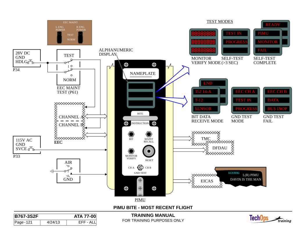
TRAINING MANUALFOR TRAINING PURPOSES ONLY
B767-3S2F ATA 77-00 Page - 121 4/24/13 EFF - ALL
PIMU BITE - MOST RECENT FLIGHT
EICAS
L(R) PIMUECS/MSG
TMC
DFDAU
CH BCH A
RECALLMAINT
GND TEST
RESETVERIFY
MONITOR
BIT
NAMEPLATE
BITE
INSTRUCTION
ALPHANUMERICDISPLAY
FAILGND TEST
MODEGND TEST
RECEIVE MODEBIT DATA
SELF-TESTCOMPLETE
MONITORVERIFY MODE (>3 SEC)
SELF-TEST
TEST MODES
EEC
CHANNEL B
CHANNEL A
AIR
GND
P33
GNDSVCE
115V AC
PIMU
SENSOR
T-12
352 14-A
BUS INOP
DATA
EEC CH B
PROGRESS
TEST IN
EEC CH A
END
FAIL
MONITOR
PIMU
READY
PROGRESS
TEST IN
TEST (P61)EEC MAINT
P34
28V DCGNDHDLG
NORM
TEST
TEST
NORM
EEC MAINT
POWERR ENGL ENG
POWER
EEC
DAVIN IS THE MAN
TRAINING MANUALFOR TRAINING PURPOSES ONLY
B767-3S2F ATA 77-00 Page - 122 4/24/13 EFF - ALL
ENGINE INDICATION SYSTEM - PIMU GROUND TEST
General
The PIMU ground test is used to determine if there are any current faults detected by the EEC. Both the EEC and the PIMU must be powered to conduct the test. There are three ways to power the EEC.
• Put the EEC maintenance switch (P61 panel) to the TEST position • Motor the engine above 11% N2 • Start the engine
To supply power to the PIMU, the 115vac ground service bus must be powered.
Operation
Push the RESET switch to erase any faults stored in the PIMU non volatile memory. Test the PIMU by pushing the MONITOR VERIFY switch and releasing it. Wait for the message READY to appear and then go out.
A spring loaded return-to-off toggle switch on the PIMU starts the test. Push the switch to the CH A position and release. Wait 10 seconds. The message TEST IN PROGRESS appears. The display then blanks. Push the switch to CH B position and release. Wait 10 seconds. The message TEST IN PROGRESS appears. The display then blanks. If a channel is not powered, the message DATA BUS INOP will appear.
If there are active faults detected by the EEC, they will be received by the PIMU and stored in non volatile memory. To view any faults that the PIMU has recorded in NVM, push the BIT switch once for each fault. If there are no faults or if you have viewed all the faults detected, the message END appears.
To remove fault data from the PIMU, push RESET. This will erase PIMU NVM faults but will not erase the faults that are stored in the EEC.
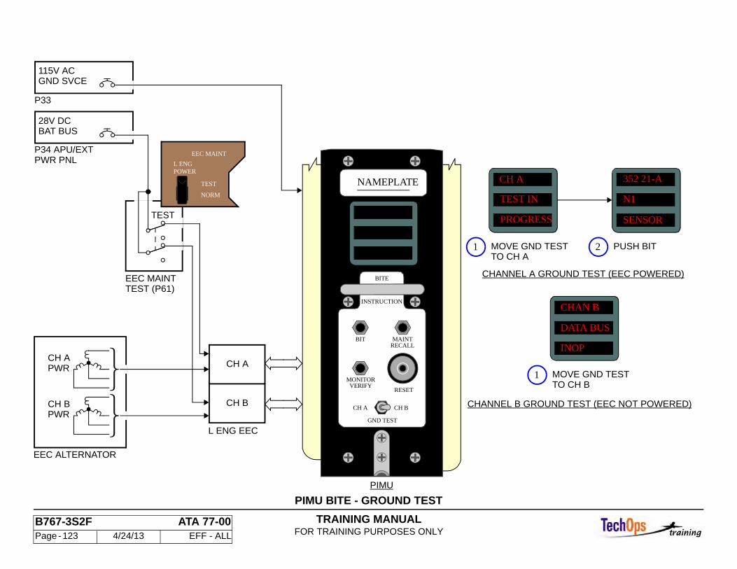
TRAINING MANUALFOR TRAINING PURPOSES ONLY
B767-3S2F ATA 77-00 Page - 123 4/24/13 EFF - ALL
PIMU BITE - GROUND TEST
CH BCH A
RECALLMAINT
GND TEST
RESETVERIFY
MONITOR
BIT
NAMEPLATE
BITE
INSTRUCTION
PIMU
CHANNEL B GROUND TEST (EEC NOT POWERED)
CHANNEL A GROUND TEST (EEC POWERED)
PWRCH A
PWRCH B
EEC ALTERNATOR
CH A
CH B
L ENG EEC
DATA BUS
N1
352 21-A
TEST IN
CH A
SENSORPROGRESS
INOP
CHAN B
P33
GND SVCE115V AC
P34 APU/EXT
28V DCBAT BUS
PWR PNL
EEC MAINTTEST (P61)
TO CH B
1 MOVE GND TESTTO CH A
1 MOVE GND TEST
PUSH BIT2
TEST
NORM
TEST
EEC MAINT
L ENGPOWER
TRAINING MANUALFOR TRAINING PURPOSES ONLY
B767-3S2F ATA 77-00 Page - 124 4/24/13 EFF - ALL
ENGINE INDICATION SYSTEM - PIMU MAINTENANCE RECALL
General
The maintenance recall procedures allow the recall of the fault history stored in the EEC. Faults from the most recent flight, flight 1, will be displayed first. Then the faults for the next oldest flight that had faults can be shown on the PIMU. This procedure allows us to look at the fault history of that channel of that engine for the last 64 flight legs.
The maintenance recall procedure will transfer faults only for the channel in control of the engine at that time. The engine must be shut down and maintenance ground power applied to the EEC. The faults are brought over from the EEC NVM into the PIMU’s random access memory, one fault at a time.
To view the faults that have been recorded in the EEC NVM for the other channel, exit the maintenance recall mode by pushing the MONITOR VERIFY switch, un-power that EEC by cycling the maintenance ground test switch to NORM, then back to the TEST position, and finally pull the appropriate engine channel circuit breaker. This procedure changes the channel-in-control as shown on the EPCS EICAS page.
Operation
Push the MONITOR VERIFY switch to test the PIMU. READY will show if there are no faults in the PIMU itself. Pushing the MAINTENANCE RECALL switch begins the transfer of data from the EEC NVM to the PIMU random access memory (RAM), one fault bit at a time. You must wait 5 seconds while TEST IN PROGRESS is shown. When the transfer of the fault is completed, the FLIGHT LEG # message appears.
Pushing the BIT switch will display the fault. The dollar ($) symbol between the label and bit designation shows that this is maintenance mode data from the EEC NVM. Only faults for the channel in control will be shown. Pushing the BIT switch again and again will toggle between the fault just seen and the flight leg number. To see the next fault you must push the MAINTENANCE RECALL switch, wait for 5 seconds until the FLIGHT LEG # is shown, and then push the BIT switch to display the fault.
The Fault Isolation Manual only requires that the latest flight leg with faults be recalled. For historical data or to analyze recent problems, it may be required to recall all of the faults for all possible 64 flights. A maximum of 40 faults can be recalled for each channel.
To get the faults from the opposite channel, exit the maintenance mode with the MONITOR VERIFY switch, shut off the ground test power, turn the ground test power back on, and pull the appropriate circuit breaker to change the channel in control. The recall procedure for the other channel can then be done.
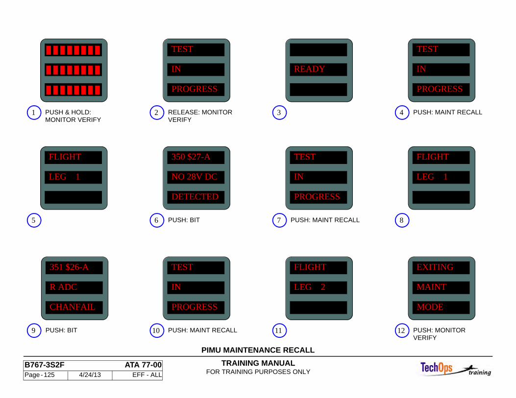
TRAINING MANUALFOR TRAINING PURPOSES ONLY
B767-3S2F ATA 77-00 Page - 125 4/24/13 EFF - ALL
PIMU MAINTENANCE RECALL
MODE
MAINT
EXITING
LEG 2
FLIGHTTEST
IN
PROGRESSCHANFAIL
R ADC
351 $26-A
LEG 1
FLIGHTTEST
IN
PROGRESSDETECTED
NO 28V DC
350 $27-A
LEG 1
FLIGHT
TEST
IN
PROGRESS
TEST
IN
PROGRESS
READY
PUSH: MAINT RECALLVERIFYPUSH: MONITOR1211PUSH: BIT9 10
5 PUSH: MAINT RECALLPUSH: BIT6 87
PUSH: MAINT RECALLVERIFYRELEASE: MONITOR2 43
MONITOR VERIFYPUSH & HOLD:1
TRAINING MANUALFOR TRAINING PURPOSES ONLY
B767-3S2F ATA 77-00 Page - 126 4/24/13 EFF - ALL
ENGINE INDICATION SYSTEM - ELECTRONIC PROPULSION CONTROL SYSTEM (EPCS)
General
The values for various engine controls and status parameters appear on the EPCS maintenance pages 1 and 2. The parameters are shown as real time. AUTO EVENT or MAN EVENT data.
EPCS Page 1
Data from both channels of the EEC on each engine appear. The channel which is currently in control of the engine operations is indicated by a square around the channel letter. In the case of the AUTO / MAN EVENT the square displayed indicates the channel which controlled that engine at the time the event was recorded.
EPCS Page 2
Page 2 of the EPCS display is accessed by pressing the EPCS maintenance switch a second time. Page 2 is real time information only. There is no MAN / AUTO EVENTS for this page. The hexi-decimal ARINC 429 labels can be decoded using the FIM manual, with the PIMU MESSAGE INDEX.
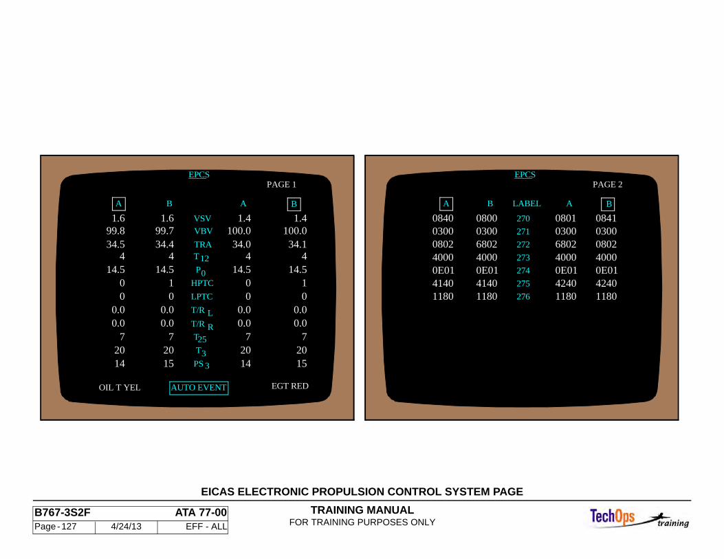
TRAINING MANUALFOR TRAINING PURPOSES ONLY
B767-3S2F ATA 77-00 Page - 127 4/24/13 EFF - ALL
EICAS ELECTRONIC PROPULSION CONTROL SYSTEM PAGE
A
0840 0800 0801
080203000841
AB
____EPCS
BA
14
7
0.00
14.5 4
34.0100.0
1.4
0
20
0.0 0.0 7
15
0.00
14.5 4
34.1100.0
1
20
1.6
0.00.0 0 1
14.5 4
34.4 99.7
15 20
7
B
1.6
A
0.0 0.0 0 0
14.5 4
34.5 99.8
14 20
7
____EPCS
AUTO EVENTOIL T YEL
3
VBV
TRA
B
T
EGT RED
VSV
LPTC
R
LT/R
T/R
HPTC
T 25
T12
PS 3
0P
PAGE 1 PAGE 2
1.4
LABEL
270
271
272
273
274
275
276
0300680240000E0141401180
0300680240000E01
1180
40000E01
1180
0300080240000E0141401180
4240 4240
TRAINING MANUALFOR TRAINING PURPOSES ONLY
B767-3S2F ATA 77-00 Page - 128 4/24/13 EFF - ALL
ENGINE CONTROL - CLUTCH AND MICROSWITCH PACKS
General
The autothrottle clutch pack assembly is the interface between the autothrottle system and the engine fuel control system. It is in the forward equipment center.
The microswitch pack is linked to the clutch pack assembly through the forward cable drum. It is the interface to other aircraft systems. The switch pack is below the drum.
Autothrottle Clutch Packs
The autothrottle clutch packs supply friction and feel for the thrust levers (manual) and let the autothrottle servo unit move the thrust levers. The clutch packs are on a common shaft. The thrust levers connect to one face of a clutch pack. The autothrottle servo unit connects to the other face of both clutch packs.
The clutch friction is set to supply the correct feel when the thrust levers are moved manually against the autothrottle servo unit. When the autothrottle is engaged, the autothrottle servo unit moves the thrust levers through the clutch packs. In reverse thrust, the autothrotle clutch cannot increase engine thrust. In reverse thrust, all thrust changes are manual. The clutch packs make manual override of the servo unit possible at all times.
Microswitch Pack
The microswitch pack has two cam-following arms and two sets of switches for each engine. Cam surfaces machined on the lower half of the forward drums move the arms. This operates the switches to send thrust lever position signals to other aircraft systems.
Training Information Point
The switches of the microswitch pack may be replaced, but the entire switch pack must first be removed. There is an adjustment screw for each microswitch.
These screws are adjusted to have all switches in the group operate at the same time. In addition, there is an adjustment bolt for each group. Adjust the bolt to get the switches to operate at the correct thrust lever angle.
To adjust the switch group, put the thrust levers at the proper angle as described in the Maintenance Manual. A scale on the forward drum shows the position. Push on the lock channel to disengage the adjustment bolt. Turn the bolt to adjust the switch. Make sure the position is correct by a continuity test on the applicable pins in the electrical connector. When the position is correct, release the lock channel to re-engage the bolt.
Switches
These are the switches:
• S1, S5 - L/R LANDING WARNING • S2, S3 - L AUTOBRAKE/AUTOBRAKE REJECTED TAKEOFF (RTO) • S6, S7 - R AUTOBRAKE/AUTOBRAKE REJECTED TAKEOFF (RTO) • S8, S11 - L/R THRUST REVERSER DIRECTIONAL CONTROL VALVE • S10, S14 - L/R SPEEDBRAKE RETRACT • S12, S16 - L/R THRUST MANAGEMENT SYSTEM (TMS) THRUST
REVERSE • S17 - LOAD SHED/PRESSURE CONTROL L • S18 - LOAD SHED/PRESSURE CONTROL R.
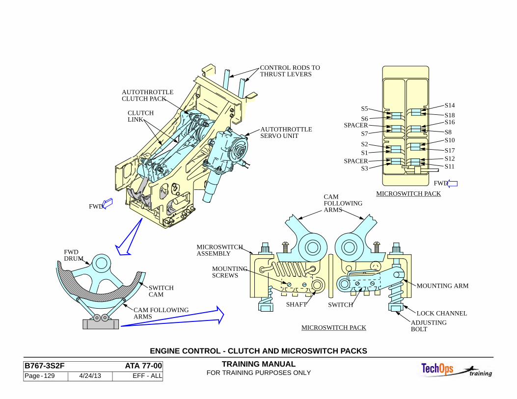
TRAINING MANUALFOR TRAINING PURPOSES ONLY
B767-3S2F ATA 77-00 Page - 129 4/24/13 EFF - ALL
ENGINE CONTROL - CLUTCH AND MICROSWITCH PACKS
S7SPACER
S5
S6
SPACERS3
S2S1
MICROSWITCH PACK
FWD
ARMSCAM FOLLOWING
MICROSWITCH PACK
SWITCHCAM
S8
S16S18
S14
S10
S17
S11
MICROSWITCHASSEMBLY
CAMFOLLOWINGARMS
CLUTCHLINK
CLUTCH PACKAUTOTHROTTLE
THRUST LEVERSCONTROL RODS TO
SERVO UNITAUTOTHROTTLE
SHAFT
SCREWSMOUNTING
SWITCH
MOUNTING ARM
LOCK CHANNEL
ADJUSTING
DRUM
FWD
BOLT
FWD
S12
TRAINING MANUALFOR TRAINING PURPOSES ONLY
B767-3S2F ATA 77-00 Page - 130 4/24/13 EFF - ALL
ENGINE CONTROL - THRUST LEVER ANGLE (TLA) RESOLV-ERS
General
The thrust levers control engine thrust. Each thrust lever is mechanically linked through the autothrottle clutchpack to a two-channel thrust lever angle (TLA) resolver. The TLA resolver is a rotary transducer. The clutchpack turns the resolver rotor when the thrust lever is moved. The resolvers are on the clutchpack assemblies in the forward equipment center. Access is through the forward equipment center access door.
Each resolver has two sets of electrical outputs that are a function of the thrust lever angle. One signal from each resolver goes to EEC channel A, the other signal goes to EEC channel B.
Each EEC channel sends a sine wave signal through its respective connector to the rotor of the dual coil TLA resolver. The excitation induces a sine-cosine feedback signal for each channel as the rotor moves in response to power lever position changes. The EEC converts the sensed analog feedback signals into a digital thrust lever angle value. The EEC uses this phase angle to determine commanded N1.
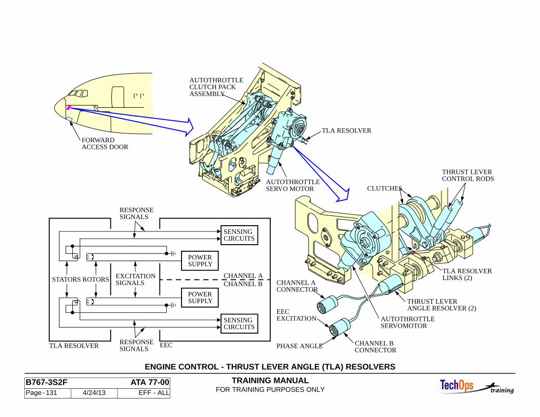
TRAINING MANUALFOR TRAINING PURPOSES ONLY
B767-3S2F ATA 77-00 Page - 131 4/24/13 EFF - ALL
ENGINE CONTROL - THRUST LEVER ANGLE (TLA) RESOLVERS
ACCESS DOORFORWARD
EECEXCITATION
PHASE ANGLE
AUTOTHROTTLESERVOMOTOR
SIGNALSRESPONSE
SIGNALSRESPONSE
CHANNEL BCHANNEL AEXCITATION
SIGNALSROTORSSTATORS
TLA RESOLVER EEC
SUPPLY
CIRCUITSSENSING
POWER
CIRCUITSSENSING
SUPPLYPOWER
AUTOTHROTTLESERVO MOTOR
TLA RESOLVER
AUTOTHROTTLECLUTCH PACKASSEMBLY
TLA RESOLVERLINKS (2)
ANGLE RESOLVER (2)THRUST LEVER
THRUST LEVERCONTROL RODS
CLUTCHES
CHANNEL A
CHANNEL B
CONNECTOR
CONNECTOR
TRAINING MANUALFOR TRAINING PURPOSES ONLY
B767-3S2F ATA 76-00 Page - 132 4/24/13 EFF - ALL
ENGINE CONTROL SYSTEM - FADEC SYSTEM DESCRIPTION
General
The General Electric CF6-80C2 full authority digital electronic control (FADEC) system is a computer-based engine control system. Each engine on the 767 has its own independent engine control system. The main component of the FADEC system is the electronic engine control (EEC). The FADEC system is divided into subsystems to perform two basic functions - information processing and engine control.
The information processing functions receive, manipulate and send large amounts of data. The EEC gets information about the environment and operating conditions within the engine. This information comes form engine control switches in the flight deck, thrust lever position inputs, temperature and presser inputs on the engine. The EEC uses this information to control the engine through the EEC which also sends data and messages to EICAS, the SEI and the engine discrete card. The flight management computer (FMC), thrust management computers (TMC) and the air data computers (ADC) also interface with the EEC.
The engine control functions control the engine fuel and air systems to operate the engine efficiently at all rated performance levels. The FADEC system is composed of an engine control (EEC), Hydro-Mechanical Unit (HMU), Permanent Magnet Alternator (PMA), Engine rating Plug, Engine Identification Plug, engines sensors and components from the Variable Stator Vane (VSV), Variable Bleed Valve (VBV), HPT Active Clearance Control (HPTACC) and Engine Starting and Ignition systems. It is divided into seven separate subsystems that provide two basic system functions - Information Processing and Engine Control:
• Information processing refers to the FADEC's ability to input, manipulate and output large amounts of electronic data. Using these functions, the FADEC computer gathers information about the environment and operating conditions within the engine. With the information, the computer calculates fuel and air flows required to maintain engine operation at the rated performance levels with peak efficiency. Information processing also allows the FADEC computer to communicate directly with other computerized aircraft systems including the:
• Engine Indicating and Crew Alerting System (EICAS) • Air Data Computer (ADC)
• Auto-Throttle System (ATS)
It is extensive information processing capabilities, more than any other, that distinguishes FADEC from mechanical engine control systems.
ENGINE CONTROL refers the FADEC's ability to physically control the operating, performance and efficiency characteristics of the engine. Capabilities in this area include precise control over fuel flow, primary and parasitic airflow, internal rotor to stator clearances (Active Clearance Control), engine start sequencing and igniter operation.
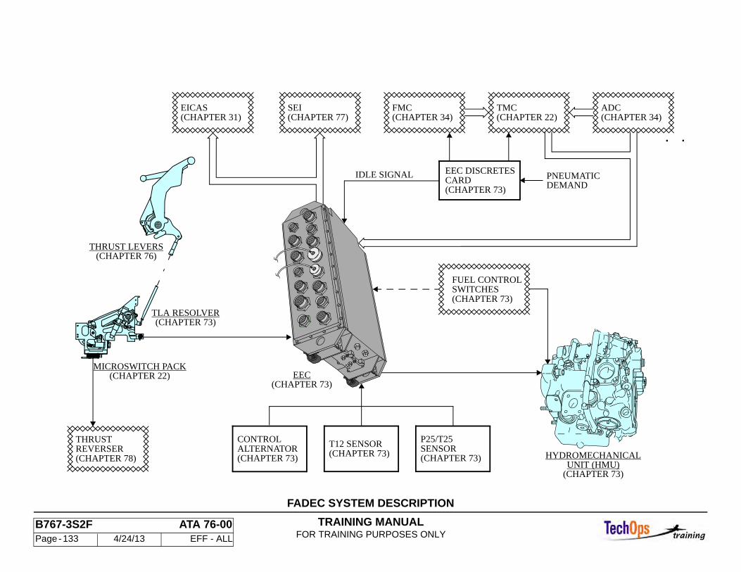
TRAINING MANUALFOR TRAINING PURPOSES ONLY
B767-3S2F ATA 76-00 Page - 133 4/24/13 EFF - ALL
FADEC SYSTEM DESCRIPTION
. .
SWITCHESFUEL CONTROL
(CHAPTER 73)
T12 SENSOR(CHAPTER 73)
CONTROLALTERNATOR(CHAPTER 73)
P25/T25SENSOR(CHAPTER 73)
TLA RESOLVER(CHAPTER 73)
MICROSWITCH PACK(CHAPTER 22)
EICAS(CHAPTER 31)
(CHAPTER 73)EEC
DEMANDCARD(CHAPTER 73)
EEC DISCRETESIDLE SIGNAL
(CHAPTER 22)(CHAPTER 34)TMCFMC
(CHAPTER 34)ADC
(CHAPTER 77)SEI
PNEUMATIC
(CHAPTER 76)THRUST LEVERS
THRUSTREVERSER(CHAPTER 78)
UNIT (HMU)HYDROMECHANICAL
(CHAPTER 73)
TRAINING MANUALFOR TRAINING PURPOSES ONLY
B767-3S2F ATA 76-00 Page - 134 4/24/13 EFF - ALL
ENGINE CONTROL SYSTEM - ELECTRONIC ENGINE CON-TROL (EEC)
The electronic engine control (EEC) manages the following engine functions:
• Compressor airflow control (Chapter 75) • Core compartment cooling (75) • Turbine case cooling (75) • Engine/aircraft interface (EICAS , TMC, etc..) (76) • Power management in response to commanded thrust (76) • Engine limit protection (76) • Built-in testing (76) • Fault detection (76) • Engine status indications (77) • Maintenance indications (77) • Thrust reverser interlock and control (78) • Start/Ignition control (74/80)
The EEC is a two channel (A and B), digital electronic microcomputer. It is mounted using vibration isolators on the left side of the fan case at the 8:30 position. There are fifteen electrical connectors on the front side of the unit, identified as J1 through J15. Engine wiring harnesses are color coded for easy identification. There are four connections for pressure robes on the bottom of the unit. The unit is cooled by natural convection.
The EEC is designed to support a variety of engine/aircraft combinations and different thrust ratings. An engine Identification Plug on connector J15 programs the EEC for desired application. The plug is attached to the engine fan case by a lanyard and remains with the engine if the EEC is changed. It must be connected to the EEC to dispatch the airplane. The EEC has two modes of operation: control and test. The EEC is normally in the control mode. It is in test mode if the airplane is on the ground, the fuel control switch is in CUTOFF, and the EEC ground test switch on the P61 panel is in the TEST position.
Various airplane and engine systems communicate with the EEC and have redundant paths to the EEC channels (channel A and channel B). The 15 electrical connectors on the EEC are grouped by aircraft interfaces (J1-J6), on-engine components (J7-J13) and EEC use (J14-J15).
Aircrft Interface Connectors (J1-J6)
• J1 Ignition Exciter #1. DC Power In/Out; Channel A Ground Handeling Bus Power In
• J2 Ignition Exciter #2. DC Power In/Out; Channel B Ground Handeling Bus Power In
• J3 Fuel On; Starter Air Valve Open; Chanel A Reset: EEC Fault; Digital Data Bus (ADC & TMC) In/Out, Channel A TLA resolver In/Out
• J4 Single/Dial; Igniters; Idle Select; Hard Reversionary Mode; Channel B TLA Resolver In/Out
• J5 Aircraft Type; Engine Position (L/R); channel A Thrust reverser Position • TMC Disconnect; Operating Mode Select (Control or Test); Channel B
Thrust Reverser Position
Engine Interface Connectors
• J7 Black Channel A • J8 Brown Channel B • N2 Sensor; ESCV Solenoid, Escv Position Switches; HMU • J9 red Channel A • J10 Orange Channel B • Control Alternator; Starter Air Valve; N1 Sensor; T12 • J11 Yellow Channel A • J12 Green Channel B • T2.5; HPTC Valve; VSV Actuators; VBV Actuators • J13 Blue Channel A and B • T3; T49; T5; Engine Oil Temperature Sensort; Fuel Flow Transmitter
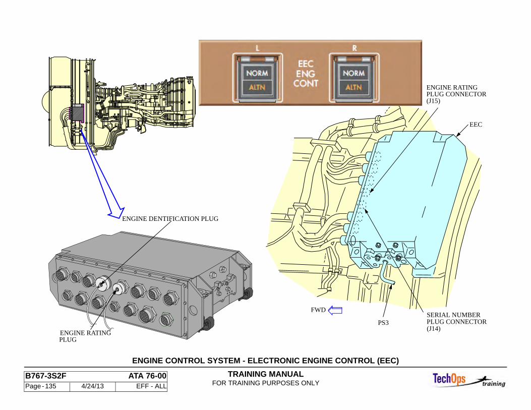
TRAINING MANUALFOR TRAINING PURPOSES ONLY
B767-3S2F ATA 76-00 Page - 135 4/24/13 EFF - ALL
ENGINE CONTROL SYSTEM - ELECTRONIC ENGINE CONTROL (EEC)
EEC
ENGINE RATINGPLUG CONNECTOR(J15)
SERIAL NUMBERPLUG CONNECTORPS3(J14)
FWD
ENGINE DENTIFICATION PLUG
ENGINE RATINGPLUG
TRAINING MANUALFOR TRAINING PURPOSES ONLY
B767-3S2F ATA 76-00 Page - 136 4/24/13 EFF - ALL
ENGINE CONTROL SYSTEM - ELECTRONIC ENGINE CON-TROL (EEC) (CONT)
Data Plugs
• J15 Engine Rating Plug • J14 Identification Plug
These two plugs are captive to the engine by lanyards. Multiple tables are contained in the EEC and the P14 determines the rating table to be used. The P15 provides engine hardware informatin to the EEC:
• N1 Modifier • EGT Shunt Valve • Active Clearance Control Schedules • Engine Serial Number (Programed Through J15)
Pressure Inputs
The EEC has pressure transducer and signal conditioning circuits. The pressures measured are as follows:
• Ambient Pressure (PO) • Compressor Discharge Pressure (Ps3)
One transducer for each channel measures PO through a small hole in the EEC case. A tube for Ps3 goes to the EEC. The two channels send data to each other on a crosstalk data bus.
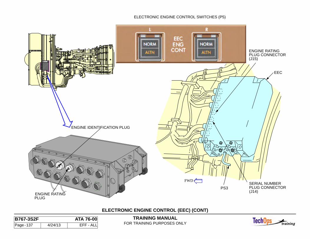
TRAINING MANUALFOR TRAINING PURPOSES ONLY
B767-3S2F ATA 76-00 Page - 137 4/24/13 EFF - ALL
ELECTRONIC ENGINE CONTROL (EEC) (CONT)
EEC
ENGINE RATINGPLUG CONNECTOR(J15)
SERIAL NUMBERPLUG CONNECTORPS3(J14)
FWD
ENGINE IDENTIFICATION PLUG
ENGINE RATINGPLUG
ELECTRONIC ENGINE CONTROL SWITCHES (P5)
TRAINING MANUALFOR TRAINING PURPOSES ONLY
B767-3S2F ATA 76-00 Page - 138 4/24/13 EFF - ALL
ENGINE CONTROL SYSTEM - CONTROL ALTERNATOR
Purpose
The control alternator provides the EEC channels A and B with electrical power.
Characteristics
The alternator is located on the forward center section of the accessory gearbox. Opening the thrust reverser allows access.
The alternator consists of two separate assemblies:
• Rotor • Stator
Rotor
The rotor is a permanent magnet assembly - Permanent Magnet Alternator - PMA. It is mounted to the Accessory Gearbox (AGB) splined drive shaft with a lock nut.
Stator
The stator mounts on the AGB case with three bolts. The stator has three independent windings. Two windings power the EEC channels A and B.
Operation
The alternator operates whenever the gearbox is turning. It will meet all required EEC power at 11% N2. It continues to meet the power requirements until the N2 decreases below 9%. If one phase of either or both windings fail, the control alternator continues to meet all EEC power requirements if the N2 is above 45%.

TRAINING MANUALFOR TRAINING PURPOSES ONLY
B767-3S2F ATA 76-00 Page - 139 4/24/13 EFF - ALL
PERMENANT MAGNET ALTERNATOR
O-RING
NUT
SHAFTAGB DRIVE
MOUNTING PAD
CHANNEL B
CHANNEL A
ROTOR
FLATS (3)
WINDINGS (2)
MAGNETSPERMANENT
STATOR
TRAINING MANUALFOR TRAINING PURPOSES ONLY
B767-3S2F ATA 76-00 Page - 140 4/24/13 EFF - ALL
ENGINE CONTROL SYSTEM - INLET SENSORS (T12)
Engine Inlet Temperature Sensor (T12)
There are two T12 Inlet temp sensors. Each supplies inlet temp data to one of the EEC channels. The sensors are identical and are mounted on the forward edge of the fan case at the 2:00 and 10:00 positions. The elements in the sensor are resistive thermal devices. Hence, temperature changes in the engine inlet area varies the resistance of the probes. The housing the sensor is mounted in protects it from physical damage. It also prevents water and ice contact interfering with the accurate operation of the probe.
The T12 sensor is used by the EEC to correct N1 and N2 speed inputs, and to calculate the position of the Fuel Metering Valve and the HPTACC Valve. Inputs from the sensor mounted in the 2:00 position are received and processed by Channel A, and channel B inputs are from the sensor mounted at the 10:00 position.
Each EEC channel supplies a 10 ma direct current excitation signal to its respective sensor. The voltage drop across the sensor is measured by the EEC and corrected for ram air effects to determine the inlet air temperature. The digital equivalent of each input is made available at the aircraft interface for monitoring.
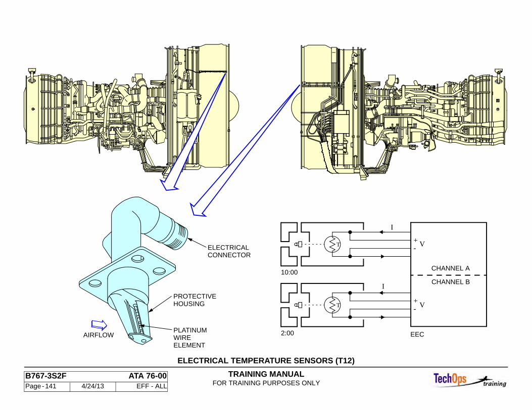
TRAINING MANUALFOR TRAINING PURPOSES ONLY
B767-3S2F ATA 76-00 Page - 141 4/24/13 EFF - ALL
ELECTRICAL TEMPERATURE SENSORS (T12)
2:00
10:00
T
T
CHANNEL B
EEC
CHANNEL A
-+
+-
V
V
I
I
HOUSINGPROTECTIVE
ELEMENTWIREPLATINUM
CONNECTORELECTRICAL
AIRFLOW

TRAINING MANUALFOR TRAINING PURPOSES ONLY
B767-3S2F ATA 76-00 Page - 142 4/24/13 EFF - ALL
ENGINE CONTROL SYSTEM - INLET SENSORS (P/T 2.5)
General
The P2.5 probe is a part of the compressor inlet temperature/pressure T2.5/P2.5 sensor. The P2.5 probe senses the total pressure of the high pressure compressor inlet airflow.
The T2.5/P2.5 sensor is on the fan frame hub outer surface at the 7:30 position.The P2.5 probe has a pitot tube to sense pressure. The pressure signal goes to a P2.5 pressure transducer in the EEC. The operation range of the P2.5 input to the EEC is from 2 to 75 psia.
Compressor Inlet Temperature/Pressure Sensor (T2.5)
The compressor inlet temperature sensor (T2.5), is part of the T2.5/P2.5 temperature sensor. This sensor is mounted on the fan frame at the 7:30 position between the number 8 and 9 fan struts. The sensor has two separate temperature sensing elements, one for each channel of the EEC. Once again temperature varies resistance in this sensor and that change is read by the EEC as a temperature.
The T2.5 is used by the EEC to correct N2 speed inputs. Two T2.5 inputs are received from the sensor. One input is received and processed by Channel A, and the other by Channel B. Each channel supplies 10 ma (max) direct current excitation signal to the sensor. The digital equivalent of each input is made available at the aircraft interface for monitoring.
Note: The P2.5 portion of this sensor is not currently used.
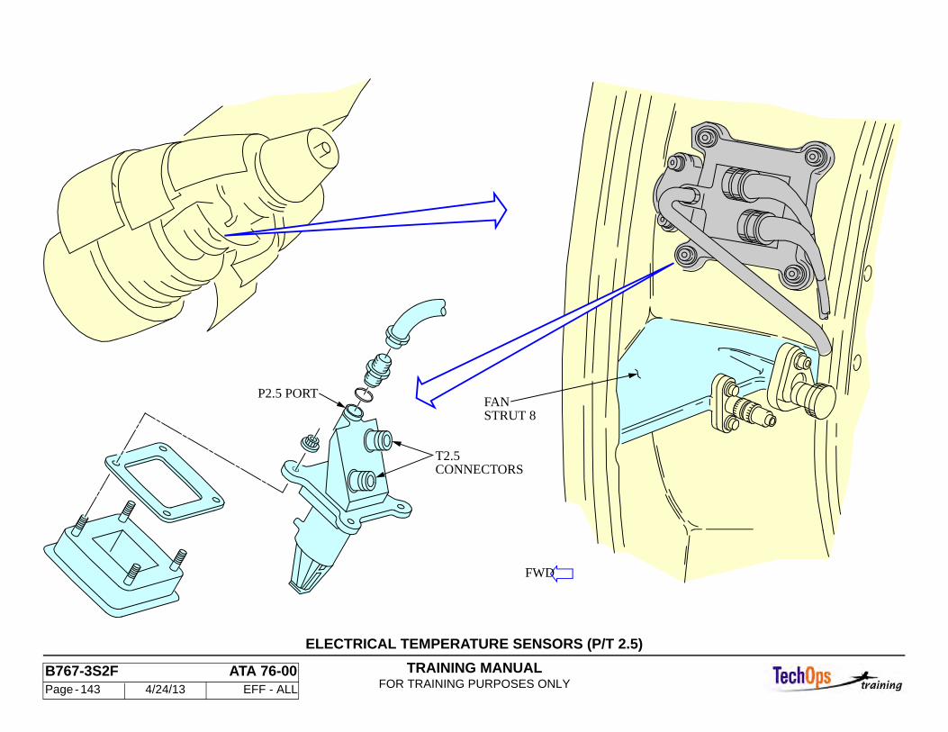
TRAINING MANUALFOR TRAINING PURPOSES ONLY
B767-3S2F ATA 76-00 Page - 143 4/24/13 EFF - ALL
ELECTRICAL TEMPERATURE SENSORS (P/T 2.5)
P2.5 PORT
CONNECTORST2.5
FAN STRUT 8
FWD
TRAINING MANUALFOR TRAINING PURPOSES ONLY
B767-3S2F ATA 76-00 Page - 144 4/24/13 EFF - ALL
ENGINE CONTROL SYSTEMS - EEC DISCRETES PRINTED CIRCUIT CARD
One EEC discrete’s printed circuit card serves both engines. It is an interface between various pneumatic user systems and the TMC and FMC. The TMC supplies both EEC’s with bleed state information. The card also supplies a time-delay for the idle select control circuits.
The card is in the P50 card file in the main equipment center. Relays on the card connect in puts and outputs. The card has two sections, one for each engine. The 28vdc battery bus and the left 28vdc bus supply power to the card's left engine section. The 28vdc battery bus and the right 28vdc bus supplies power to the card's right engine section.
CAUTION: THIS CARD IS STATIC SENSITIVE. DO NOT HANDLE BEFORE READING THE PROCEDURE FOR HANDLING ELECTROSTATIC DISHARGE SENSITIVE DEVICES (REF 20-41-01). THE CARD CONTAINS DEVICES THAT CAN BE DAMAGED BY STATIC DISCHARGE.
Characteristics
The card is a printed circuit type. Relays on the card provide interface between inputs and outputs. The card has two sections, one for the left engine and one for the right. The left engine section is shown.
Power
The left engine section of the card is powered by the 28 volt dc battery bus and the left 28 volt dc bus, the right engine section is powered by the 28 volt dc bat. bus and the right 28 volt dc bus.
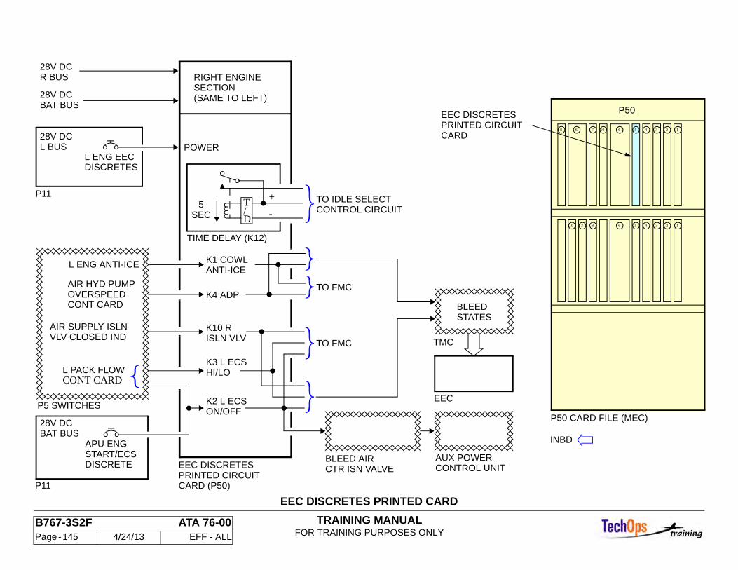
TRAINING MANUALFOR TRAINING PURPOSES ONLY
B767-3S2F ATA 76-00 Page - 145 4/24/13 EFF - ALL
EEC DISCRETES PRINTED CARD
P50 CARD FILE (MEC)
(SAME TO LEFT)
RIGHT ENGINESECTION
INBD
EEC DISCRETESPRINTED CIRCUITCARD
P50
6
310
1076
8 6 5 4 3 2 1
8 5 4 3 2 1
P11
P11
CONTROL UNITAUX POWER
CTR ISN VALVEBLEED AIR
EEC DISCRETES
CARD (P50)PRINTED CIRCUIT
ISLN VLV TO FMC
K2 L ECS
K10 R
OVERSPEEDCONT CARD
TO FMC
K3 L ECS
K4 ADP
ON/OFF
HI/LO
ANTI-ICEK1 COWL
CONT CARDL PACK FLOW
VLV CLOSED INDAIR SUPPLY ISLN
AIR HYD PUMP
L ENG ANTI-ICE
BAT BUS
DISCRETESTART/ECSAPU ENG
28V DC
CONTROL CIRCUIT
TIME DELAY (K12)
SEC5
-
+
D
T
POWER
DISCRETESL ENG EEC
L BUS28V DC
BAT BUS28V DC
R BUS28V DC
TO IDLE SELECT
EEC
TMC
BLEEDSTATES
/
P5 SWITCHES
TRAINING MANUALFOR TRAINING PURPOSES ONLY
B767-3S2F ATA 76-00 Page - 146 4/24/13 EFF - ALL
ENGINE CONTROL SYSTEM - HMU FUEL METERING OPERA-TION
General
Fuel flow is metered by the hydro-mechanical unit (HMU) mounted on the front right side of the accessory gearbox. In addition, the HMU supplies servo fuel for the operation of the engine air system. The HMU gets control signals from the EEC and the aircraft.
Fuel Metering Valve
A fuel metering valve (FMV) inside the HMU controls fuel flow to the fuel nozzles. The hydraulically driven metering valve is controlled by the FMV EHSV. Control of the EHSV is through two coils , one for each EEC channel. The controlling EEC channel increases current through its EHSV coil to hydraulically open the FMV. The FMV has two position indicating resolvers, each providing feedback to and getting power from it’s own respective EEC channel.
High Pressure Fuel Shutoff Valve
A solenoid controls the position of the high pressure fuel shutoff valve (HPSOV). The fuel control switch and engine fire switch on the P10 panel control the HPSOV solenoid. The solenoid gets power directly from the 28 volt battery bus. It has two latching coils:
• Run • Cutoff
Placing the fuel control switch to RUN energizes the run coil of the HPSOV solenoid. Placing the fuel control switch to CUTOFF, or pulling the engine fire switch, energizes the cutoff coil of the HPSOV solenoid. The solenoid is magnetically latched in the last commanded position.
When the HPSOV solenoid is in the cutoff position, the HPSOV sends high pressure servo fuel to the pressurizing and shutoff valve to stop metered fuel flow to the fuel nozzles. When the solenoid is in the run position, the high pressure servo fuel is cutoff and the pressurizing and shutoff valve can open.
When the pressurizing and shutoff valve is closed, a permanent magnet mounted to a translating structure on the valve is in close proximity with three reed-type switches. The magnet closes the three switches. One of the switch outputs goes to EEC channel A, one to EEC channel B, and one to the ENG VALVE disagreement light circuit. The EICAS level C message L(R) ENG FUEL VAL appears if the pressurizing and shutoff valve actual and commanded positions disagree. The ENG VALVE light on the P10 panel also comes on when the valve actual and commanded positions disagree.
Bypass Valve
The bypass valve has a piston inside a multi ported sleeve. Un-metered fuel from the fuel pump enters the sleeve, is blocked by the piston, and is forced out of the sleeve ports. The fuel flow rate to the FMV, and the bypass return flow to the fuel pump, are controlled by moving the piston in and out of the sleeve, varying the number of outlet ports. The piston position is controlled by the delta P regulator.
The delta P regulator maintains a constant pressure drop across the FMV. This makes the fuel flow rate vary with the FMV position.
The regulator monitors the pressure difference between the un-metered fuel input and the metered fuel output developed across the FMV. The regulator positions the bypass valve to equalize the two fuel pressures. If the FMV input pressure increases above the output pressure, the delta P regulator opens the bypass valve to increase bypass fuel flow to the fuel pump. If the FMV input pressure decreases below the output pressure, the bypass valve closes to decrease bypass fuel flow..
.
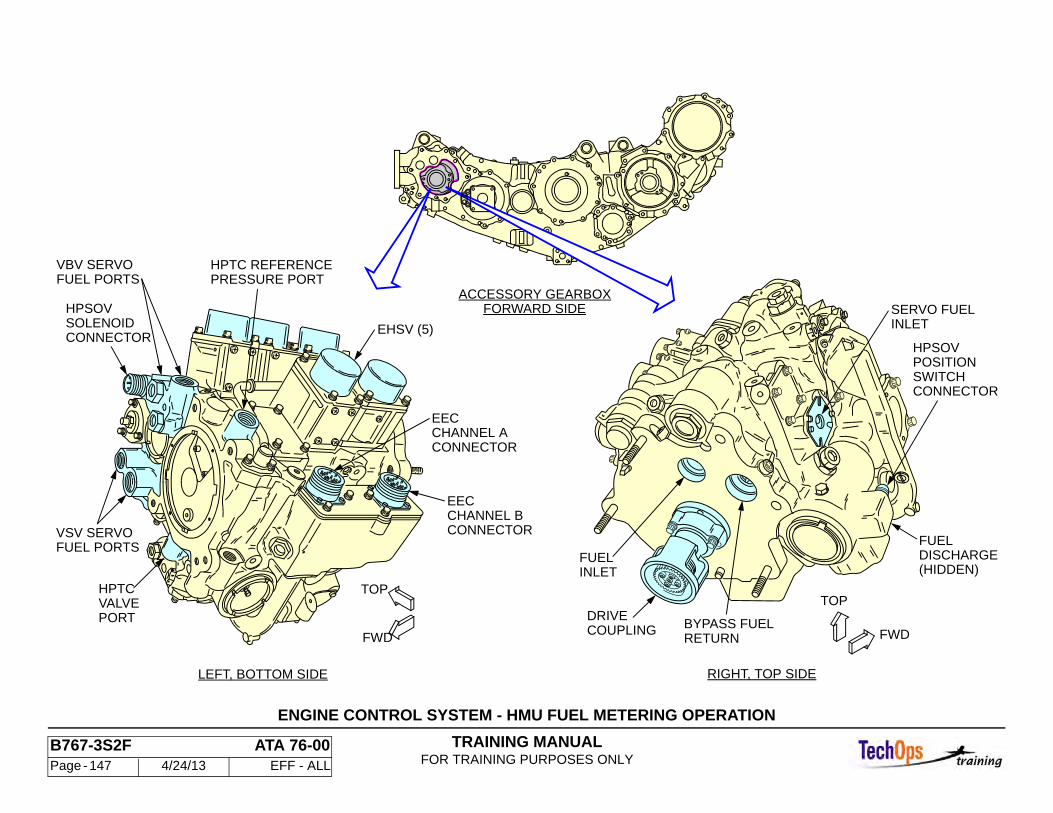
TRAINING MANUALFOR TRAINING PURPOSES ONLY
B767-3S2F ATA 76-00 Page - 147 4/24/13 EFF - ALL
ENGINE CONTROL SYSTEM - HMU FUEL METERING OPERATION
EHSV (5)
HPTC
PORTVALVE
LEFT, BOTTOM SIDE
CONNECTOR
EECCHANNEL B
CONNECTOR
EECCHANNEL A
FUEL PORTSVBV SERVO
PRESSURE PORTHPTC REFERENCE
CONNECTORSOLENOIDHPSOV
FUEL PORTSVSV SERVO
TOP
FWD COUPLINGDRIVE
FWD
FUELDISCHARGE(HIDDEN)
RIGHT, TOP SIDE
SERVO FUELINLET
HPSOVPOSITIONSWITCHCONNECTOR
BYPASS FUEL
TOP
RETURN
FUELINLET
FORWARD SIDEACCESSORY GEARBOX
TRAINING MANUALFOR TRAINING PURPOSES ONLY
B767-3S2F ATA 76-00 Page - 148 4/24/13 EFF - ALL
ENGINE CONTROL SYSTEMS - HYDROMECHANICAL UNIT (HMU) (CONT)
The fuel metering system is completely contained in the Hydromechanical Unit (HMU). The HMU is mounted on the front, right side of the accessory gearbox. It is driven by a mechanical connection to the gearbox. The HMU responds to electrical signals from the EEC to meter fuel flow for combustion and to modulate servo fuel flow to operate the engine air systems. The HMU also receives signals from the aircraft fuel control system to control an internal high pressure fuel shutoff valve (HPSOV). Access to the HMU is through the right thrust reverser half.
There are four electrical connectors for electrical interfaces with the aircraft and MU with the fuel pump and nozzles. There are five hydraulic connections for control interface with the engine fuel and air systems. Each hydraulic interface is controlled by an electro-hydraulic servo valve (EHSV) that varies servo fuel pressure in response to EEC signals.
The fuel connections are:
• Fuel inlet from the fuel pump • Fuel discharge to the fuel nozzles • Fuel bypass discharge to the fuel pum • Servo fuel inlet from the servo fuel heater
The hydraulic connections are:
• Servo fuel pressure to the Low Pressure Turbine Cooling Valve (LPTC) • Servo fuel pressure to the High Pressure Turbine Cooling Valve (HPTC) • Servo fuel reference pressure to the LPTC and HPTC valves • Servo fuel pressure to the variable bypass valves (VBV’s) • Servo fuel pressure to the Variable Stator Vanes (VSV’s)
Note: The LPTC system is currently not used on the 767. The EHSV is still located on the HMU, however the control valve has been removed. The system flows constantly without and external control systems.
The electrical connections to the HMU are:
• Fuel control signals from the EEC channel A • Fuel control signals from the EEC channel B • HPSOV solenoid inputs from the fuel control valves • HPSOV position indicating outputs to the EEC

TRAINING MANUALFOR TRAINING PURPOSES ONLY
B767-3S2F ATA 76-00 Page - 149 4/24/13 EFF - ALL
ENGINE CONTROL SYSTEMS - HYDROMECHANICAL UNIT (HMU) (CONT)
EHSV (5)
HPTC
PORTVALVE
LEFT, BOTTOM SIDE
CONNECTOR
EECCHANNEL B
CONNECTOR
EECCHANNEL A
FUEL PORTSVBV SERVO
PRESSURE PORTHPTC REFERENCE
CONNECTORSOLENOIDHPSOV
FUEL PORTSVSV SERVO
TOP
FWD COUPLINGDRIVE
FWD
FUELDISCHARGE(HIDDEN)
RIGHT, TOP SIDE
SERVO FUELINLET
HPSOVPOSITIONSWITCHCONNECTOR
BYPASS FUEL
TOP
RETURN
FUELINLET
FORWARD SIDEACCESSORY GEARBOX
TRAINING MANUALFOR TRAINING PURPOSES ONLY
B767-3S2F ATA 76-00 Page - 150 4/24/13 EFF - ALL
ENGINE CONTROL SYSTEM - HMU FUEL METERING OPERA-TION (CONT)
Overspeed Governor
The overspeed governor senses N2 speed through the HMU mechanical drive from the accessory gearbox. If the N2 exceeds 113.4 percent, the governor overides the delta P regulator input to the bypass valve to reduce the metered fuel flow regardless of the FMV position.
When the overspeed governor operates, it closes an overspeed indication switch inside the HMU. This switch is connected to the EEC. When the switch closes, the latched EICAS status and maintenance message L(R) ENG S/O GOV appears.
When the engine is started, remaining fuel between the spar valve and the pressurizing and shutoff valve causes the overspeed governor to operate, closing the overspeed switch. The overspeed governor returns to normal operation at 50% N2. This performs a functional test of the overspeed governor. If the switch does not close during engine start, the L (R) ENG O/S GOV message appears.
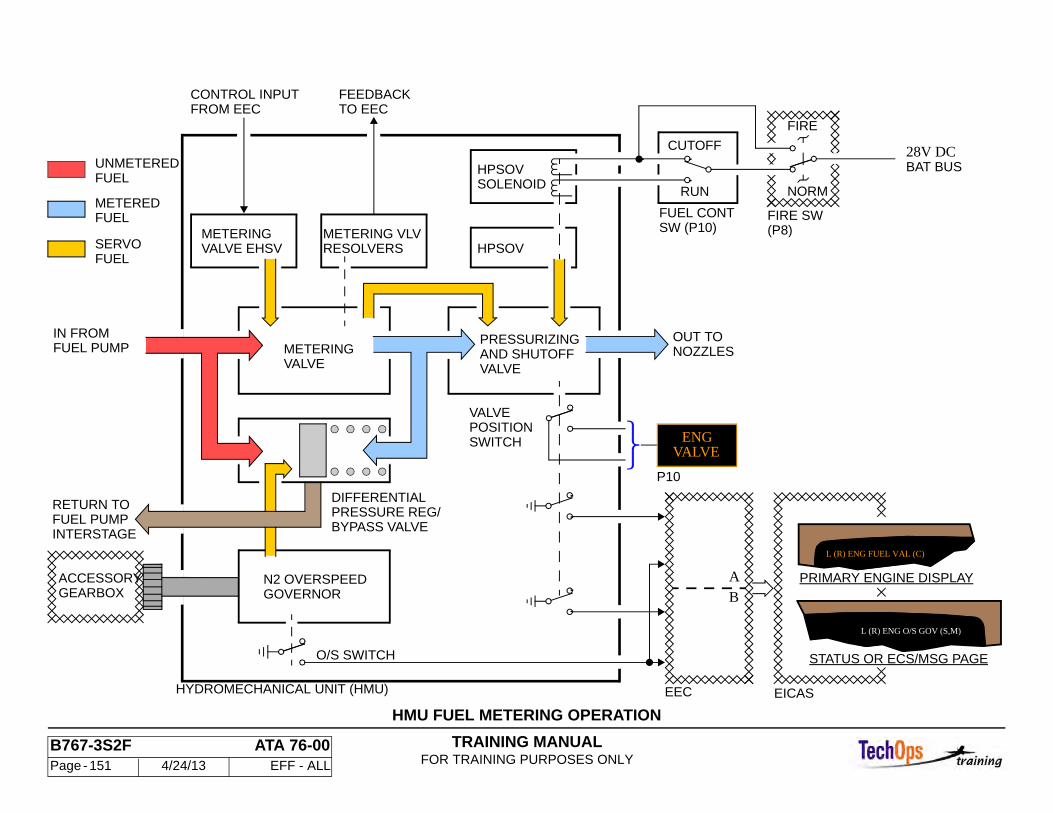
TRAINING MANUALFOR TRAINING PURPOSES ONLY
B767-3S2F ATA 76-00 Page - 151 4/24/13 EFF - ALL
HMU FUEL METERING OPERATION
EICAS
METERINGVALVE EHSV
BAT BUS28V DC
FIRE SW
NORM
FIRE
P10
A
EEC
B
SW (P10)FUEL CONT
FEEDBACKTO EEC
CONTROL INPUTFROM EEC
INTERSTAGEFUEL PUMPRETURN TO
O/S SWITCH
METERED
FUELSERVO
FUEL
FUELUNMETERED
SWITCH
VALVEPOSITION
GEARBOXACCESSORY
SOLENOIDHPSOV
HPSOV
AND SHUTOFFVALVE
PRESSURIZINGFUEL PUMPIN FROM
DIFFERENTIALPRESSURE REG/BYPASS VALVE
RESOLVERSMETERING VLV
METERINGVALVE
GOVERNORN2 OVERSPEED
HYDROMECHANICAL UNIT (HMU)
ENGVALVE
CUTOFF
RUN
NOZZLESOUT TO
(P8)
L (R) ENG O/S GOV (S,M)
STATUS OR ECS/MSG PAGE
PRIMARY ENGINE DISPLAY
L (R) ENG FUEL VAL (C)
TRAINING MANUALFOR TRAINING PURPOSES ONLY
B767-3S2F ATA 76-00 Page - 152 4/24/13 EFF - ALL
ENGINE CONTROL SYSTEM - EEC INPUTS/OUTPUTS
The EEC gets analog input data from the engine and aircraft. It also receives digital input data and discrete inputs from the aircraft. The EEC uses power from the Permanent Magnet Alternator (PMA) when the engine is running, and from the aircraft when the engine is not running.
The EEC sends analog output signals to the hydro-mechanical unit (HMU), engine air systems, thrust reverser interlock and start/ignition systems. The EEC sends digital signals to EICAS and the propulsion interface monitor unit (PIMU). The two EEC channels are redundant and independent. Each channel receives the same inputs. The system is designed so that no single failure causes the engine to stop running.
The EEC includes extensive self-test and fault recovery features. When the EEC is on, it monitors all critical functions and inputs. If an input signal is faulty or missing, the EEC usually uses the value input to the other EEC channel. If that input is faulty or missing, the EEC often calculates an approximate value for the missing data. The EEC takes the following actions when input data is faulty or missing:
• Engine sensor data is used to backup the air data computer (ADC) TAT and PO values.
• The EEC calculates a mach number if MACH is not received from the ADC. • Cross-channel data is used if T12 or PO sensor data is invalid. If cross-
channel data is invalid, the EEC switches to the soft reversionary mode. • Comparisons are made between N1, N2, P3 or T2.5 sensor data inputs
using cross-channel data. If sensor values disagree, the closest to an EEC calculated value is used; if both sensor values are lost or invalid, EEC calculated values are used.
• Comparisons are made between TLA data inputs using cross-channel data. If both inputs are lost or invalid, the last TLA value is used during takeoff; otherwise, the TLA is reduced to idle.
• The EEC calculates values for the HMU fuel metering valve, VSV actuator and VBV actuator if the position data is invalid or missing.
• The HPTC, CCC valves and the thrust reverser interlocks fail-safe to open or closed.
• The EEC uses 28vdc aircraft power if power is not available from the control alternator.
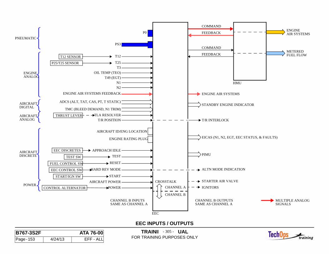
TRAINING MANUALFOR TRAINING PURPOSES ONLY
B767-3S2F ATA 76-00 Page - 153 4/24/13 EFF - ALL
EEC INPUTS / OUTPUTS
- 305 -- 305 -
P0
PS3
ENGINE AIR SYSTEMS FEEDBACK
N2N1
T49 (EGT)
OIL TEMP (TEO)
T12
T3T25
T12 SENSOR
P25/T25 SENSOR
SAME AS CHANNEL ACHANNEL B INPUTS
POWER
ANALOGAIRCRAFT
DIGITALAIRCRAFT
ANALOGENGINE
PNEUMATIC
ADCS (ALT, TAT, CAS, PT, T STATIC)
T/R POSITION
TMC (BLEED DEMAND, N1 TRIM)
TLA RESOLVERTHRUST LEVER
DISCRETEAIRCRAFT
ENGINE RATING PLUG
AIRCRAFT ID/ENG LOCATION
CONTROL ALTERNATOR POWER
CROSSTALKAIRCRAFT POWER
START
HARD REV MODE
RESET
TEST
APPROACH IDLE
START/IGN SW
EEC CONTROL SW
FUEL CONTROL SW
TEST SW
EEC DISCRETES
SIGNALSMULTIPLE ANALOG
ENGINE AIR SYSTEMS
CHANNEL B OUTPUTS
T/R INTERLOCK
STANDBY ENGINE INDICATOR
COMMAND
FEEDBACK
FEEDBACK
COMMAND
HMU
METEREDFUEL FLOW
AIR SYSTEMSENGINE
CHANNEL A
CHANNEL B
PIMU
EICAS (N1, N2, EGT, EEC STATUS, & FAULTS)
SAME AS CHANNEL A
ALTN MODE INDICATION
STARTER AIR VALVE
IGNITORS
EEC
TRAINING MANUALFOR TRAINING PURPOSES ONLY
B767-3S2F ATA 76-00 Page - 154 4/24/13 EFF - ALL
ENGINE CONTROL SYSTEM - EEC OPERATION
The two EEC channels (A and B) are identical and equally capable of controlling the engine. Each channel contains:
• a power supply • central processor unit • digital interface unit • signal conditioning unit • data interface unit • solenoid driver unit
The channels are physically separated within the EEC.
The internal power supply for each EEC channel gets three-phase ac power from separate windings of the control alternator when the engine is running (N2 greater than 11 percent). Aircraft power is supplied when:
• the engine is being started • the engine fuel control switch is in the RUN position • the EEC maintenance engine power switch is in the TEST position
Normally, aircraft power is used for ignition, pneumatic starter control valve operation, and power for some of the internal EEC solenoid drivers. Control alternator power is used for all other EEC functions.
If both channels are healthy, the channel in control of the engine switches with every engine start. If one or both channels have faults, the healthiest channel is always selected as the active channel during engine starting. If a fault is detected in the active channel during engine run, the standby channel takes control if it is healthier than the other channel. If both channels have faults, the channel with the least severe fault(s) takes control. If both channels have failed, the engine is shut down. Detected faults are stored in the volatile memory of each channel. Fault information is shared between the two channels through the crosstalk data bus.
Pressure transducers and signal conditioners for pressure inputs are located inside the EEC. There are separate pressure sensor circuits for each channel.
When the engine is running, both channels have power, receive input signals, process data, and send information to aircraft systems and to the other EEC channel. However, only the active channel operates the servo valves, solenoids and relays to control the engine. Similar outputs from the standby channel are terminated inside the EEC by switching relays.
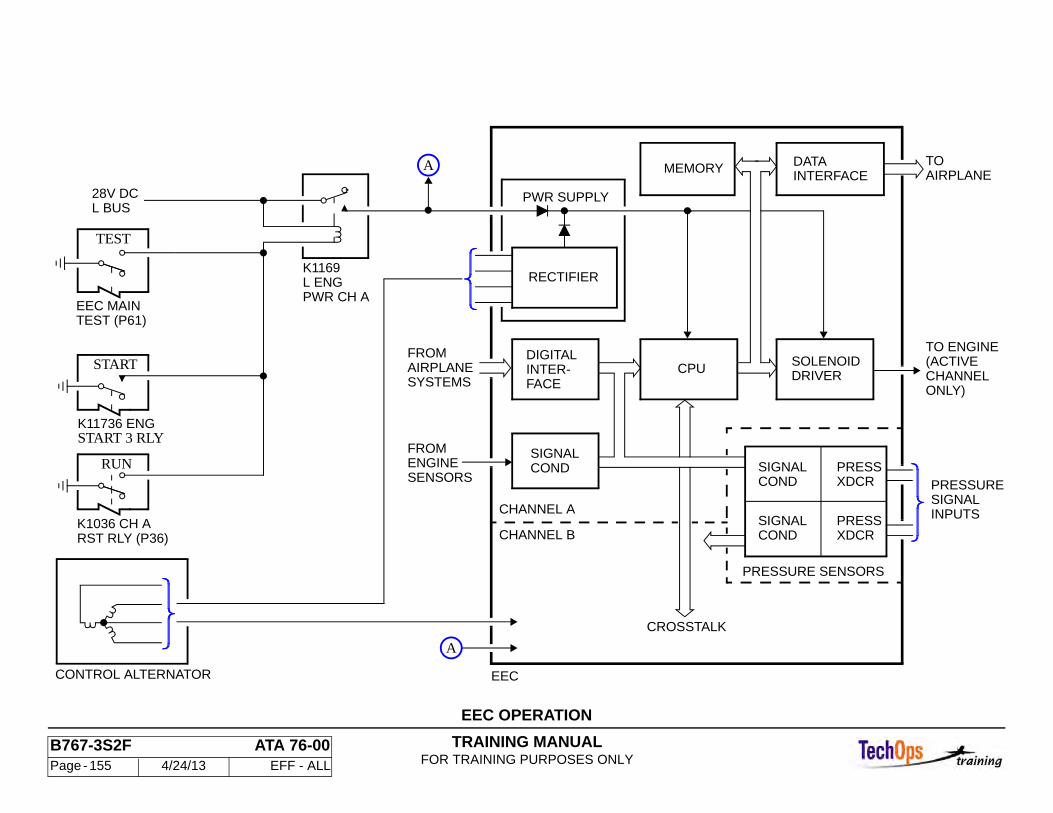
TRAINING MANUALFOR TRAINING PURPOSES ONLY
B767-3S2F ATA 76-00 Page - 155 4/24/13 EFF - ALL
EEC OPERATION
RST RLY (P36)K1036 CH A
RUN
START 3 RLYK11736 ENG
START
TEST (P61)EEC MAIN
TEST
CONTROL ALTERNATOR
L BUS28V DC
PWR CH AL ENGK1169
SENSORSENGINEFROM
CHANNEL A
CHANNEL B
SIGNALCOND
EEC
SYSTEMSAIRPLANE
RECTIFIER
PWR SUPPLY
DIGITALINTER-FACE
FROM
INTERFACEDATA
DRIVERSOLENOIDCPU
MEMORYTOAIRPLANE
XDCRPRESS
XDCRPRESS INPUTS
SIGNALPRESSURE
TO ENGINE(ACTIVECHANNELONLY)
CONDSIGNAL
CONDSIGNAL
CROSSTALK
PRESSURE SENSORS
A
A
TRAINING MANUALFOR TRAINING PURPOSES ONLY
B767-3S2F ATA 76-00 Page - 156 4/24/13 EFF - ALL
ENGINE CONTROL SYSTEM - CHANNEL RESET AND FUEL ON
Channel Reset
The channel reset signal causes the EEC to alternate the active channel between channel A and channel B. Both EEC channels get a reset signal through the reset relays when the fuel control switch is moved to CUTOFF. Channel A also gets a reset signal if the fire switch is pulled. If a channel reset signal is received while channel A is the active channel, channel B will become the new active channel if it is at least as healthy as channel A. If channel A is healthier than channel B, channel A will remain the active channel.
Fuel On
When the fuel control switch is set to RUN and the fire switch is set to NORM, a fuel-on signal is sent to both EEC channels. The EEC will then send signals to the solenoid valve inside the HMU to latch open the Pressurizing and Shutoff Valve. When the fuel control switch is set to the CUT-OFF position a signal is sent to the EEC and it signals the latch closed solenoid in the HMU to close the Pressurizing and Shutoff Valve. The fire switch pulled up to the FIRE position will also signal the EEC to close the Pressurizing and Shutoff Valve.
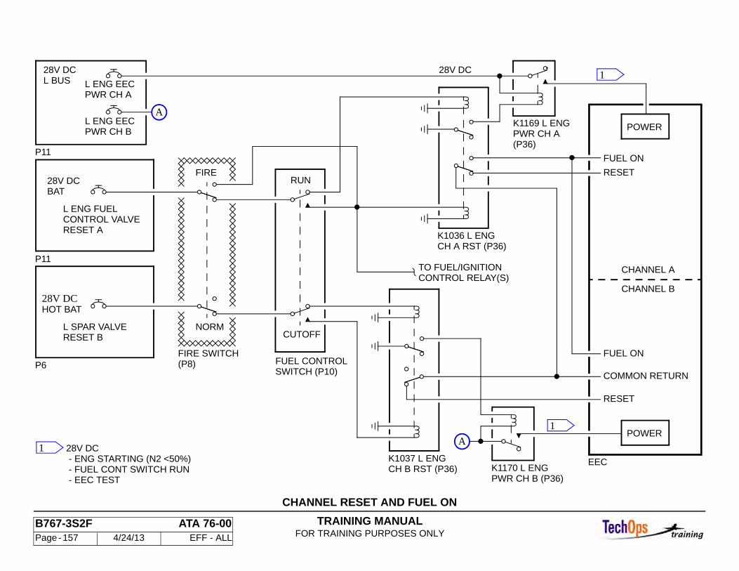
TRAINING MANUALFOR TRAINING PURPOSES ONLY
B767-3S2F ATA 76-00 Page - 157 4/24/13 EFF - ALL
CHANNEL RESET AND FUEL ON
RESET B
CH B RST (P36)PWR CH B (P36)
CH A RST (P36)
(P36)PWR CH A
POWER
L BUS28V DC 28V DC
EEC
FUEL ON
COMMON RETURN
RESET
CHANNEL B
CHANNEL A
POWER
FUEL ON
RESET
K1036 L ENG
FUEL CONTROLSWITCH (P10)
CUTOFF
RUN
P11
P6
P11
28V DCHOT BAT
L SPAR VALVE
FIRE SWITCH(P8)
NORM
FIRE
K1037 L ENG28V DC - ENG STARTING (N2 <50%) - FUEL CONT SWITCH RUN - EEC TEST
PWR CH BL ENG EEC
PWR CH AL ENG EEC
K1170 L ENG
K1169 L ENG
TO FUEL/IGNITIONCONTROL RELAY(S)
BAT28V DC
L ENG FUELCONTROL VALVERESET A
1
1
1
A
A
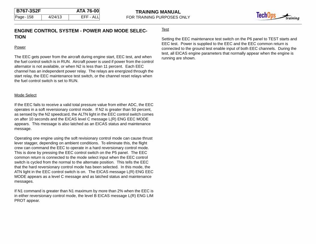
TRAINING MANUALFOR TRAINING PURPOSES ONLY
B767-3S2F ATA 76-00 Page - 158 4/24/13 EFF - ALL
ENGINE CONTROL SYSTEM - POWER AND MODE SELEC-TION
Power
The EEC gets power from the aircraft during engine start, EEC test, and when the fuel control switch is in RUN. Aircraft power is used if power from the control alternator is not available, or when N2 is less than 11 percent. Each EEC channel has an independent power relay. The relays are energized through the start relay, the EEC maintenance test switch, or the channel reset relays when the fuel control switch is set to RUN.
Mode Select
If the EEC fails to receive a valid total pressure value from either ADC, the EEC operates in a soft reversionary control mode. If N2 is greater than 50 percent, as sensed by the N2 speedcard, the ALTN light in the EEC control switch comes on after 10 seconds and the EICAS level C message L(R) ENG EEC MODE appears. This message is also latched as an EICAS status and maintenance message.
Operating one engine using the soft revisionary control mode can cause thrust lever stagger, depending on ambient conditions. To eliminate this, the flight crew can command the EEC to operate in a hard reversionary control mode. This is done by pressing the EEC control switch on the P5 panel. The EEC common return is connected to the mode select input when the EEC control switch is cycled from the normal to the alternate position. This tells the EEC that the hard reversionary control mode has been selected. In this mode, the ATN light in the EEC control switch is on. The EICAS message L(R) ENG EEC MODE appears as a level C message and as latched status and maintenance messages.
If N1 command is greater than N1 maximum by more than 2% when the EEC is in either reversionary control mode, the level B EICAS message L(R) ENG LIM PROT appear.
Test
Setting the EEC maintenance test switch on the P6 panel to TEST starts and EEC test. Power is supplied to the EEC and the EEC common return is connected to the ground test enable input of both EEC channels. During the test, all EICAS engine parameters that normally appear when the engine is running are shown.
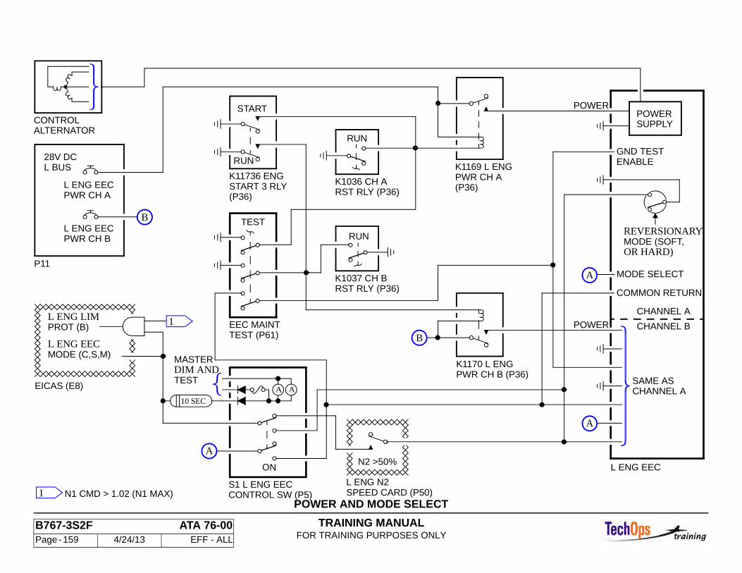
TRAINING MANUALFOR TRAINING PURPOSES ONLY
B767-3S2F ATA 76-00 Page - 159 4/24/13 EFF - ALL
POWER AND MODE SELECTSPEED CARD (P50)L ENG N2
N2 >50%ON
ALTERNATORCONTROL
10 SEC
AA
28V DCL BUS
L ENG EEC
L ENG EECPWR CH A
PWR CH B
P11
L ENG EEC
EICAS (E8)
MASTERDIM ANDTEST
START
L ENG EECMODE (C,S,M)
TEST
EEC MAINTTEST (P61)
RUN
K1037 CH B
(P36)START 3 RLY
RST RLY (P36)
RUN
K1036 CH A(P36)PWR CH AK1169 L ENG
PWR CH B (P36)K1170 L ENG
CHANNEL A
CHANNEL B
CHANNEL A
K11736 ENG
COMMON RETURN
MODE SELECT
SAME AS
POWER
S1 L ENG EECCONTROL SW (P5)
REVERSIONARY
ENABLEGND TEST
MODE (SOFT,OR HARD)
POWERSUPPLY
POWER
RST RLY (P36)
L ENG LIMPROT (B)
RUN
N1 CMD > 1.02 (N1 MAX)
1
1
B
A
A
B
A
TRAINING MANUALFOR TRAINING PURPOSES ONLY
B767-3S2F ATA 76-00 Page - 160 4/24/13 EFF - ALL
ENGINE CONTROL SYSTEM - CONTROL MODES
General
The EEC uses total air temperature (T2), ambient pressure (PO), and total pressure (PT2) to compute the N1 command needed to meet commanded thrust. The thrust rating logic uses N1 command and several EEC control systems to determine required fuel flow.
Normal Control Mode
The air data computers (ADC’s) supply T2, PO and PT2 to each EEC. The left ADC sends data to channel A. The right ADC sends data to channel B. Engine temperature sensors send air data to the EEC. The left T12 sensor data goes to channel A. The right T12 sensor data goes to channel B. Each EEC channel has a PO input. Using the crosstalk data bus, the data from both ADC’s, both T12 sensors, and both PO inputs are available to each channel.
Each EEC channel compares the total air temperature inputs (T2 LADC, T2 RADC, T12 CH A, and T12 CH B) to select a T2 value for calculating N1 command. The ambient pressure inputs (PO LADC, PO RADC, PO CH A, and PO CH B) are used to select a PO value. A PT2 value is selected by comparing total pressure inputs (PT2 LADC and PT2 RADC).
The selected PT2 value is used to calculate mach number (Mn), impact pressure (Q), the difference between ambient and standard day temperature (DTAMB), and the ambient temperature (TAMB). These values are used with T2 and PO to determine N1 command. The thrust lever angle (TLA) and bleed value received from the FMC are also used.
Soft Reversionary Control Mode
The normal control mode is used if PT2 LADC and PT2 RADC are both available and valid, and agree within 0.437 psia. Probe heat must also be ON. If these conditions are not met, the EEC automatically enters a soft reversionary control mode. If N2 is greater than 50 percent when the EEC switches to the soft reversionary control mode, the ALTN light on the EEC switch comes on,
and the EICAS level C message L(R) ENG EEC MODE appears. The most recent DTAMB value while in the normal control mode is used for the soft reversionary control mode.
This permits a smooth transition from the normal to soft reversionary modes. The fixed DTAMB value is used to calculate an assumed TAMB as altitude changes, and to calculate Mn and Q. N1 command is calculated using the assumed values for Mn, Q, TAMB and DTAMB and the PO, T2, TLA and bleed values.
If the conditions required for normal control mode operation return while the EEC is in the soft reversionary control mode, the EEC goes back to the normal control mode if the current calculated Mn is within 0.1 of the current actual Mn. This ensures that control mode change does not cause significant changes in N1.
Hard Reversionary Control Mode
If an EEC remains in a soft reversionary control mode for an extended time, the two engines will develop different thrust levels. The hard reversionary control mode permits engine operation for extended periods. Manually selecting this mode ensures that both engines supply the same thrust at the same TLA position. This mode is selected by pressing both EEC switches, the ALTN lights on the EEC switches comes on, and the EICAS level C messages L ENG EEC MODE and R ENG EEC MODE appear. In the hard reversionary control mode, the DTAMB value used in calculating N1 command corresponds to the corner point DTAMB value. The thrust can increase by using the corner point DTAMB value instead of the DTAMB value used in the soft reversionary control mode. This can cause over boosting of the engine depending on actual ambient conditions and thrust lever angle. To prevent over-boosting, the thrust levers must be pulled back to an intermediate position prior to selecting the hard reversionary control mode.
The corner point DTAMB value is used to calculate an assumed TAMB as altitude changes, and to calculate Mn and Q. N1 command is calculated using the calculated values for Mn, Q, TAMB and DTAMB and the PO, T2, TLA and bleed values.

TRAINING MANUALFOR TRAINING PURPOSES ONLY
B767-3S2F ATA 76-00 Page - 161 4/24/13 EFF - ALL
ENGINE CONTROL SYSTEM - CONTROL MODES
CMDN1
ALTERNATEMODE SELECT(USING EECSWITCH)
N2IDLE
TO EEC SW
AND EICASALTN LIGHT
PT2
TR MAX
SCHEDULEDECELACCEL/
N2
N1
TLA
T/R POS
CONTROLREVERSE
PROTECTIONN2PS3
SEL
LIMITN1
CONTROLREVERSIONARYSOFT
REVERSIONARYHARD
TAT/T12
MIN IDLEN2 MINPS3PO
CONTROL
LOGICFAULT
INPUT FAIL
EEC
FLOWFUEL
LOGICRATINGTHRUST
CONTROLNORMALPO (CH A), PO (CH B)
PO (L ADC), PO (R ADC)T12 (CH A), T12 (CH B)T2 (L ADC), T2 (R ADC)BLEED VALVES (TMC)TLA
PT2 (R ADC)PT2 (L ADC)
ADC DATA
CORNERPOINTAT AMB (30C)
LAST VALID
FROML ADC
PT2
POT2
DIGITALINTERFACE
DIGITALINTERFACE CPUFROM
PT2
POT2
R ADC
CHANNEL ACHANNEL B
CROSSCHANNELDATA BUS
CPU
TRAINING MANUALFOR TRAINING PURPOSES ONLY
B767-3S2F ATA 76-00 Page - 162 4/24/13 EFF - ALL
ENGINE CONTROL SYSTEM - CONTROL MODES (CONT)
Limit Protection
The EEC limits N1, N2 and the compressor discharge pressure (PS3). If any of the limits are approached or exceeded, the EEC reduces the fuel flow regardless of the TLA position. The N1 limit is 3,854 rpm (117.5%), the N2 limit is 11,055 rpm (112.5%), and PS3 is limited to 430psid. The N2 limit schedule is used in addition to a mechanical overspeed governor in the hydro-mechanical unit (HMU).
Acceleration / Deceleration Control
The EEC limits the N1 and N2 acceleration and deceleration rates. If the commanded thrust increase is higher than allowable, the EEC limits fuel flow to the maximum rate allowed to prevent engine overboosting. If the commanded thrust decrease is lower than allowable, the EEC maintains a fuel flow sufficient to prevent engine flame out. This control ensures that all engines respond to thrust lever angle changes at the same rate.
Idle Control
The idle control calculates N2 demand. If minimum idle is not selected, the EEC calculates a flight idle N2 demand valve based on ambient temperature and pressure. When minimum idle is selected, the flight idle N2 demand is set to 6,050 rpm (61.6 percent). The fuel flow is set to keep N2 speed at or above the flight idle N2 demand. If the N2 demand makes the compressor discharge pressure to low to meet bleed requirements, fuel flow is increased.
Reverser Control
Reverse control is active whenever the thrust reverser is not fully stowed. The EEC calculates the reverse thrust demand based on the thrust lever position. If the calculated reverse thrust N1 demand is greater than 3,280 rpm, or if the thrust demand is calculated to be greater than about 30,700 pounds, the fuel flow is reduced to ensure that these limits are not exceeded.
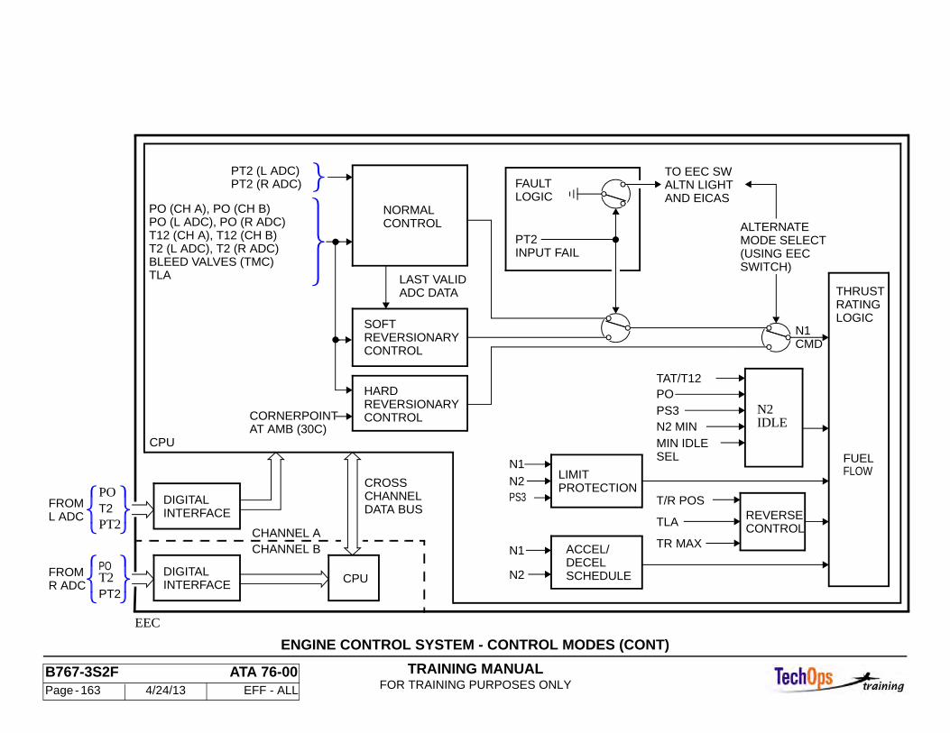
TRAINING MANUALFOR TRAINING PURPOSES ONLY
B767-3S2F ATA 76-00 Page - 163 4/24/13 EFF - ALL
ENGINE CONTROL SYSTEM - CONTROL MODES (CONT)
CMDN1
ALTERNATEMODE SELECT(USING EECSWITCH)
N2IDLE
TO EEC SW
AND EICASALTN LIGHT
PT2
TR MAX
SCHEDULEDECELACCEL/
N2
N1
TLA
T/R POS
CONTROLREVERSE
PROTECTIONN2PS3
SEL
LIMITN1
CONTROLREVERSIONARYSOFT
REVERSIONARYHARD
TAT/T12
MIN IDLEN2 MINPS3PO
CONTROL
LOGICFAULT
INPUT FAIL
EEC
FLOWFUEL
LOGICRATINGTHRUST
CONTROLNORMALPO (CH A), PO (CH B)
PO (L ADC), PO (R ADC)T12 (CH A), T12 (CH B)T2 (L ADC), T2 (R ADC)BLEED VALVES (TMC)TLA
PT2 (R ADC)PT2 (L ADC)
ADC DATA
CORNERPOINTAT AMB (30C)
LAST VALID
FROML ADC
PT2
POT2
DIGITALINTERFACE
DIGITALINTERFACE CPUFROM
PT2
POT2
R ADC
CHANNEL ACHANNEL B
CROSSCHANNELDATA BUS
CPU
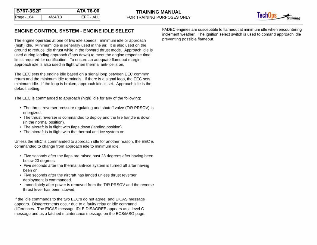
TRAINING MANUALFOR TRAINING PURPOSES ONLY
B767-3S2F ATA 76-00 Page - 164 4/24/13 EFF - ALL
ENGINE CONTROL SYSTEM - ENGINE IDLE SELECT
The engine operates at one of two idle speeds: minimum idle or approach (high) idle. Minimum idle is generally used in the air. It is also used on the ground to reduce idle thrust while in the forward thrust mode. Approach idle is used during landing approach (flaps down) to meet the engine response time limits required for certification. To ensure an adequate flameout margin, approach idle is also used in flight when thermal anti-ice is on.
The EEC sets the engine idle based on a signal loop between EEC common return and the minimum idle terminals. If there is a signal loop, the EEC sets minimum idle. If the loop is broken, approach idle is set. Approach idle is the default setting.
The EEC is commanded to approach (high) idle for any of the following:
• The thrust reverser pressure regulating and shutoff valve (T/R PRSOV) is energized.
• The thrust reverser is commanded to deploy and the fire handle is down (in the normal position).
• The aircraft is in flight with flaps down (landing position). • The aircraft is in flight with the thermal anti-ice system on.
Unless the EEC is commanded to approach idle for another reason, the EEC is commanded to change from approach idle to minimum idle:
• Five seconds after the flaps are raised past 23 degrees after having been below 23 degrees.
• Five seconds after the thermal anti-ice system is turned off after having been on.
• Five seconds after the aircraft has landed unless thrust reverser deployment is commanded.
• Immediately after power is removed from the T/R PRSOV and the reverse thrust lever has been stowed.
If the idle commands to the two EEC’s do not agree, and EICAS message appears. Disagreements occur due to a faulty relay or idle command differences. The EICAS message IDLE DISAGREE appears as a level C message and as a latched maintenance message on the ECS/MSG page.
FADEC engines are susceptible to flameout at minimum idle when encountering inclement weather. The ignition select switch is used to comand approach idle preventing possible flameout.
TRAINING MANUALFOR TRAINING PURPOSES ONLY
B767-3S2F ATA 76-00 Page - 165 4/24/13 EFF - ALL
ENGINE IDLE SELECT
CONTINUOUSIGNITION ON
P11
P11
P34
AIR/GND BAT RLY
ENG IDLE
BUSHANDLING28V DC GND
28V DCL BUS
L ENG IDLE
R ENG IDLE
R BUS28V DC
COMMONRETURN
CHANNEL A
CHANNEL B
MINIDLE
A
EICAS
R ENG
RLY (P36)DEPLOY IDLEK1025 L T/R
CIRCUITENGINETO RIGHT
(P36)VALVE RELAYK1034 L T/R
GND
K141 SYS AIR/GND RLY (P36)
AIR
GND
AIR
K167 SYS 1
(P36)LANDINGFLAPS CARD (P50)
EEC DISCRETES
T/D
5 SEC
RLY (P36)IDLE SOLK434 L
A
L FLAP/STABPOSITIONMODULE (P50)
NORMALDEPLOYED AND FIRE HANDLE
ENERGIZED WITH T/R PRSOV
K785 L ENGTAI IDLE
ONTAI
CONTROL
CONTROL
CONTROL
ENERGIZED WHEN T/R
IDLE DISAGREE (C) MESSAGE
ENG LOW IDLE (C) MSG
EEC (L ENG)
- N1 BELOW APPROACH IDLE - TAI ON
12
3
4
1
2
3
4(P36)
TRAINING MANUALFOR TRAINING PURPOSES ONLY
B767-3S2F ATA 80-00 Page - 166 4/24/13 EFF - ALL
ENGINE START SYSTEM - START SYSTEM AIR SOURCES
Ground Air
Ground air is available through the ground service pneumatic connections. The nominal required pressure is 45 psi.
APU Air
The auxiliary power unit (APU) provides approximately 54 psi air. The APU air supply shutoff valve (SOV) is controlled by APU switch on the P-5 overhead panel. The center isolation valve is normally open. The left and right isolation valves are controlled by switches on the P-5 overhead panel. During a main engine start the APU operates at a higher speed to insure adequate air flow.
Engine Air
During a cross-engine start, air from an operating engine is used to start the other engine. Two engine air sources are available; 8th stage bleed air and 14th stage bleed air. At high engine speeds, the high pressure SOV is closed and 8th stage air is used. At low engine speeds (idle to 75% N2), the high pressure SOV is open, the low pressure air supply check valve is closed, and 14th stage air is used.
General Operation
During a cross-engine start, the air supply pressure regulating and shutoff valve (PRSOV) must be open on the running engine and closed on the engine that is being started. The PRSOV is controlled by switches on the P5 overhead panel.
To pressurize the starting system, the air conditioning pack control selector must be in "OFF", the pneumatic starter control valve must be open and applicable PRSOVs (depending upon the air source) are shut. The pneumatic starter control valve is controlled by the engine start switch on pilots' overhead panel.
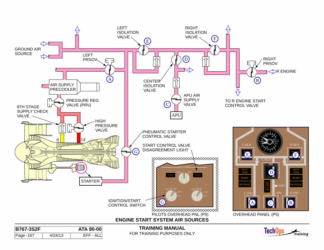
TRAINING MANUALFOR TRAINING PURPOSES ONLY
B767-3S2F ATA 80-00 Page - 167 4/24/13 EFF - ALL
ENGINE START SYSTEM AIR SOURCES
ENG START
BOTHSINGLE
AUTOOFFGND
CONT
FLT
AUTO OFFGND
CONT
FLT
L
VALVE
R
VALVE
PILOTS OVERHEAD PNL (P5)
RIGHTISOLATIONVALVE
LEFTISOLATIONVALVE
R ENGINE
CONTROL VALVE
HIGH
CONTROL VALVEPNEUMATIC STARTER
DISAGREEMENT LIGHT
APU
APU AIRSUPPLY
CENTERISOLATIONVALVE
STARTER
START CONTROL VALVE
TO R ENGINE START
CONTROL SWITCH
8 14
VALVESUPPLY CHECK8TH STAGE VALVE (PRV)
PRESSURE REG
IGNITION/START
AIR SUPPLYPRECOOLER
LEFTPRSOV
PRSOVRIGHT
PRESSUREVALVE
GROUND AIRSOURCE
VALVE
F
D
E
A B
G
C
40
60 80
20 0
DUCTPRESS
PSI
LR
R ISLN
VALVE
C ISLN
UCT
D LEAK
F
OF
L ENG
L ISLN
VALVE
LEAKDUCT
BLEED
R ENGAPU
ADP
FFO
VA
EVL
HI STAGE
E
VALV
LEAKDUCT
BLEED
HI STAGE
OVERHEAD PANEL (P5)
G
E
A
D
C
F
B
TRAINING MANUALFOR TRAINING PURPOSES ONLY
B767-3S2F ATA 80-00 Page - 168 4/24/13 EFF - ALL
ENGINE START SYSTEM - START SYSTEM COMPONENTS
Location and Features
Pneumatic Starter - The pneumatic starter is mounted to the accessory gearbox in the 6 o'clock position. It provides the initial rotation of the N2 compressor needed to ensure a successful engine start.
Pneumatic Starter Control Valve - The pneumatic starter control valve is mounted between the starter inlet and the air supply ducts and controls the flow of air to the pneumatic starter.
Engine Ignition and Start Control Module - The engine ignition and start control module located on the P5 overhead panel provides a means of controlling starting operations. The module contains two valve lights, the ignition selector switch and the two engine start switches. The operations of the switches pertaining to engine ignition are discussed in the Engine Ignition Chapter.
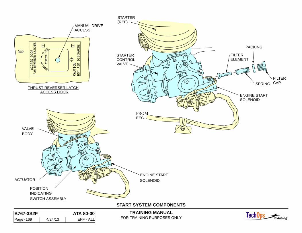
TRAINING MANUALFOR TRAINING PURPOSES ONLY
B767-3S2F ATA 80-00 Page - 169 4/24/13 EFF - ALL
START SYSTEM COMPONENTS
SPRING
SOLENOIDENGINE START
FILTERELEMENT
PACKING
FILTERCAP
EECFROM
STARTERCONTROLVALVE
(REF)STARTER
ACCESSMANUAL DRIVE
1
THRUST REVERSER LATCHACCESS DOOR
1
SOLENOID
ENGINE STARTACTUATOR
BODYVALVE
INDICATING
SWITCH ASSEMBLY
POSITION
TRAINING MANUALFOR TRAINING PURPOSES ONLY
B767-3S2F ATA 80-00 Page - 170 4/24/13 EFF - ALL
ENGINE START SYSTEM - ENGINE START CONTROL
EICAS R (L) Engine Starter Message
The EICAS level C message, L(R) ENG STARTER is displayed after a 5 second time delay if the starter valve does not open when commanded.
EICAS R (L) Starter Cutout Message
If the starter valve fails to close, or if K666 does not relax before N2 RPM reaches 52 percent, the start fail time delay is activated. After 2 seconds the engine start VALVE light illuminates by a ground through the N2 engine speed card 52 percent switch.
The EICAS level B message L(R) STARTER CUTOUT is then displayed after 5 seconds. This message inhibits all other caution and advisory messages for 20 seconds. If this occurs, position the engine ignition and start control switch to OFF, and if necessary remove pneumatic supply to the starter. Some operators procedures may require the affected engine to be shut/down.
CAUTION: IF VALVE IS NOT CLOSED WHEN N2 INDICATION SHOWS 50% RPM, STARTER MAY BE DAMAGED.
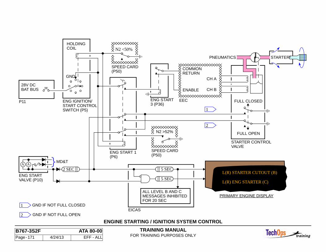
TRAINING MANUALFOR TRAINING PURPOSES ONLY
B767-3S2F ATA 80-00 Page - 171 4/24/13 EFF - ALL
ENGINE STARTING / IGNITION SYSTEM CONTROL
START CONTROLENG IGNITION/
GND IF NOT FULL OPEN
GND IF NOT FULL CLOSED
STARTER
FULL OPEN
FULL CLOSED
CH A
CH B
STARTER CONTROLVALVE
PRIMARY ENGINE DISPLAY
N2 >52%
ALL LEVEL B AND CMESSAGES INHIBITEDFOR 20 SEC
EICAS
N2 <50%HOLDINGCOIL
28V DCBAT BUS
P11
GND
2 SEC
MD&T
ENG START
PNEUMATICS
SWITCH (P5)
SPEED CARD(P50)
ENG START 1(P6)
SPEED CARD(P50)
VALVE (P10)
ENG START3 (P36)
RETURN
ENABLE
COMMON
EEC
L(R) STARTER CUTOUT (B)
L(R) ENG STARTER (C)
1
2
AA
1
2
5 SEC
5 SEC
TRAINING MANUALFOR TRAINING PURPOSES ONLY
B767-3S2F ATA 74-00 Page - 172 4/24/13 EFF - ALL
ENGINE IGNITION SYSTEM - ENGINE IGNITION LEADS, PLUGS AND START CONTROL
Location
The ignition start control and select switches are located on the P-5 overhead panel in the engine ignition and start control panel.
Ignition Select Switch
There are two positions:
• Single • Both
The switch allows either circuit 1 or 2 to be selected by the EEC, or both circuits to be selected. This selection is for both engines.
Ignition/Start Switches
There is a separate switch for each engine. The switches have five positions. These positions are
• GND • AUTO • OFF • CONT • FLT
The switch is detented in the AUTO position to prevent inadvertent selection of other switch positions.
Location
The leads run from the exciter box location at the 7 o'clock position on the left fan case, to the igniter plugs on the compressor rear frame at the 3 and 4 o'clock position.
Characteristics
The conductor is 14 AWG stranded copper wire with silicone rubber insulation within a flexible conduit. The conduit contains an inner copper braid and an outer braid of nickel wire. Tubular plastic covers the cold section of the lead and an air cooling jacket covers the hot section.
Fan air, used for cooling the lead enters through perforations at the forward end as the cable passes through a plenum. After cooling the lead, the air is discharged through a concentric port just above the coupling nut at the igniter plug.
Igniter Plugs
The igniter plug is a surface gap type used to ignite fuel within the combustion chamber. A coupling nut secures the igniter plug into a recessed adapter bolted into the compressor rear frame at two places, 4 and 3 o'clock.
The immersion depth of the igniter plug is preset at the factory using spacers under the adapter. No depth check is required.
Safety Precautions
Due to the high voltages, care should be taken with all ignition system components. See the following WARNING:
WARNING: IGNITION SYSTEM VOLTAGE IS DANGEROUSLY HIGH. IGNITION SWITCH MUST BE IN OFF POSITION BEFORE REMOVAL OF ANY IGNITION COMPONENTS. ALLOW SEVERAL MINUTES TO ELAPSE BETWEEN OPERATION OF IGNITION SYSTEM AND REMOVAL OF COMPONENTS. UPON DETACHING CABLE FROM IGNITER PLUG, DISCHARGE CURRENT BY GROUNDING CABLE TERMINAL TO ENSURE COMPLETE DISSIPATION OF ENERGY FROM THE SYSTEM. SEVERE INJURY COULD RESULT.
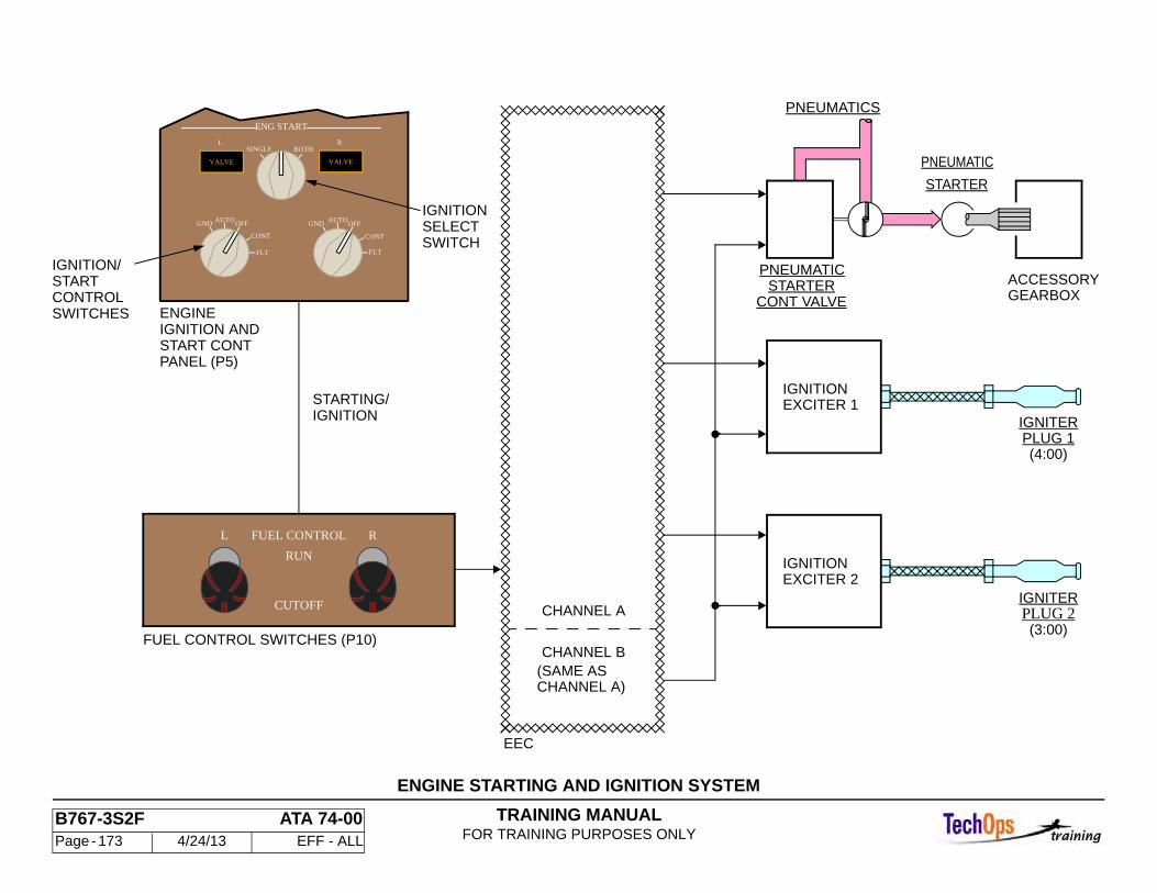
TRAINING MANUALFOR TRAINING PURPOSES ONLY
B767-3S2F ATA 74-00 Page - 173 4/24/13 EFF - ALL
ENGINE STARTING AND IGNITION SYSTEM
ENG START
BOTHSINGLE
AUTOOFFGND
CONT
FLT
AUTOOFFGND
CONT
FLT
L
VALVE
R
VALVE
EEC
CHANNEL A
CHANNEL B
CHANNEL A)(SAME AS
ENGINE
START CONTPANEL (P5)
IGNITIONSTARTING/
IGNITIONSELECTSWITCH
IGNITION/STARTCONTROLSWITCHES
ACCESSORYGEARBOX
PNEUMATICS
IGNITIONEXCITER 2
IGNITIONEXCITER 1
CONT VALVE
PNEUMATIC
STARTER
PNEUMATIC
(4:00)
IGNITERPLUG 1
(3:00)
IGNITERPLUG 2
IGNITION AND
STARTER
FUEL CONTROLL
RUN
R
CUTOFF
FUEL CONTROL SWITCHES (P10)
TRAINING MANUALFOR TRAINING PURPOSES ONLY
B767-3S2F ATA 74-00 Page - 174 4/24/13 EFF - ALL
ENGINE IGNITION SYSTEM - IGNITION ELECTRICAL POWER SUPPLY SYSTEM
Power
Power is supplied to ignition exciter 1 from the 115 volt ac left main bus or alternately from the 115 volt ac standby bus. Power for ignition exciter 2 is supplied from the 115 volt ac right main bus or the 115 volt ac standby bus.
Ignition Select and Start Control Switches
The engine ignition and start control panel located on the pilots' P-5 overhead panel contains the ignition select switch and the Ignition / Start switches for the left and right engines. The switch allows Single or Both exciters to be selected.The switch allows power to the exciters as follows:
• GND: ignition is enabled for the EEC selected igniter • AUTO: ignition is enabled for the EEC selected igniter when thermal
anti-ice is "ON" or if the slats are extended • OFF: no ignition • CONT: ignition is enabled continuously for the EEC selected igniter • FLT: ignition is enabled for both igniters bypassing the ignition select
switch
In all cases the Fuel / Ignition control relay must be de-energized to enable ignition. This requires the fire handles be in the NORM position and the fuel control switch in RUN.
Ignition Exciters
The two independent exciter units are mounted on the engine fan case, left side at 7:00 o'clock. They are electrical capacitors that are enclosed in welded steel cases.
Control and Operation
Ignition is controlled as a function of the ignition select switch, the ignition / start control switches, the fuel / ignition control relay, engine thermal anti-ice relay
and slat position. The EEC actually selects the ignition plug to fire in the SINGLE position. The EEC alternates Igniter plugs every other engine start in this position. In the BOTH position the EEC selects igniter plugs One and Two to fire together.
Displays and Indications
If the left or right AC bus is unpowered, the associated power sense relay No. 1 allows standby bus power to the system. The power sense relay No. 2 provides a ground signal to EICAS. This causes the maintenance message IGN 1(2) STBY BUS to appear.
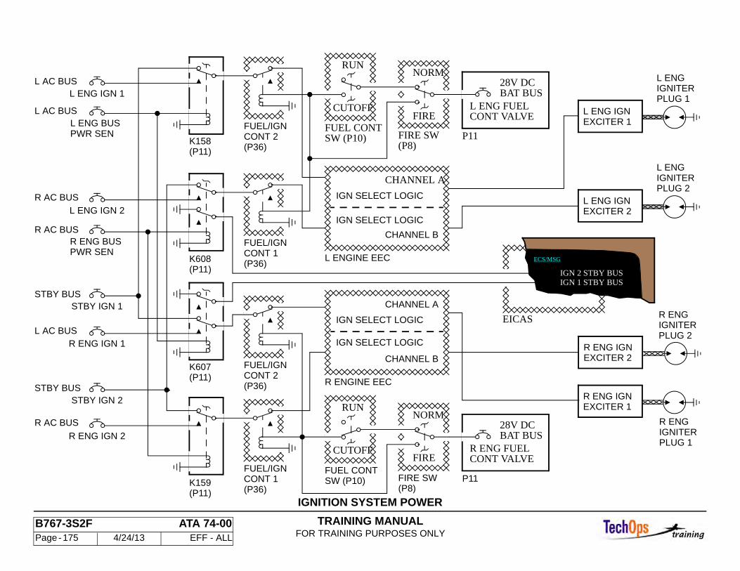
TRAINING MANUALFOR TRAINING PURPOSES ONLY
B767-3S2F ATA 74-00 Page - 175 4/24/13 EFF - ALL
IGNITION SYSTEM POWER
ECS/MSG
IGN 1 STBY BUSIGN 2 STBY BUS
CONT 1
STBY BUSSTBY IGN 2
R AC BUS
R ENG IGN 2
P11
P11
EICAS
L ENG
PLUG 2IGNITER
EXCITER 2L ENG IGN
PLUG 1IGNITERL ENG
EXCITER 1L ENG IGN
PLUG 2
R ENG
EXCITER 2R ENG IGN
IGNITER
R ENG
EXCITER 1R ENG IGN
PLUG 1IGNITER
28V DCBAT BUS
28V DCBAT BUS
R ENG FUELCONT VALVE
L ENG FUELCONT VALVE
IGN SELECT LOGIC
IGN SELECT LOGIC
IGN SELECT LOGIC
IGN SELECT LOGIC
CHANNEL A
CHANNEL B
CHANNEL A
CHANNEL B
NORM
FIRE SW
FIRE
(P8)
NORM
FIRE SW
FIRE
(P8)K159(P11)
CONT 1(P36)
FUEL/IGN
L ENGINE EEC
CONT 2(P36)
(P36)
FUEL/IGN
(P36)
R ENGINE EEC
K607
SW (P10)FUEL CONT
CUTOFF
RUN
FUEL/IGN
CONT 2FUEL/IGN
SW (P10)FUEL CONT
CUTOFF
RUN
L AC BUS
L AC BUS
R AC BUS
R AC BUS
L AC BUS
STBY BUS
(P11)K158
(P11)
K608(P11)
PWR SENL ENG BUS
L ENG IGN 1
R ENG IGN 1
L ENG IGN 2
STBY IGN 1
PWR SENR ENG BUS
TRAINING MANUALFOR TRAINING PURPOSES ONLY
B767-3S2F ATA 78-00 Page - 176 4/24/13 EFF - ALL
THRUST REVERSER - THRUST REVERSER SYSTEM
The thrust reverser, when deployed, redirects fan air forward to decelerate the airplane. The thrust reverser is normally deployed during landing rollout or during a rejected takeoff.
Each engine has two thrust reverser halves. Each half includes a translating cowl, six blocker doors with drag links, 16 deflectors, and a Center Drive Unit (CDU) with three actuators, two of which are driven through flexible drive shafts and angle gearboxes. The two translating cowls operate independently.
When the thrust reverser is stowed, the translating cowl fairs with the fan cowl and the blocker doors are retracted. In the stowed position, the thrust reverser directs fan air aft for forward thrust.
When the thrust reverser is deployed, the translating cowl slides aft to expose the deflectors and to block the fan air path with the blocker doors. This directs fan air forward, reversing the direction of thrust.
Turbine exhaust air is not reversed. While the fan air is deflected forward to provide deceleration, turbine exhaust is still providing some forward thrust.
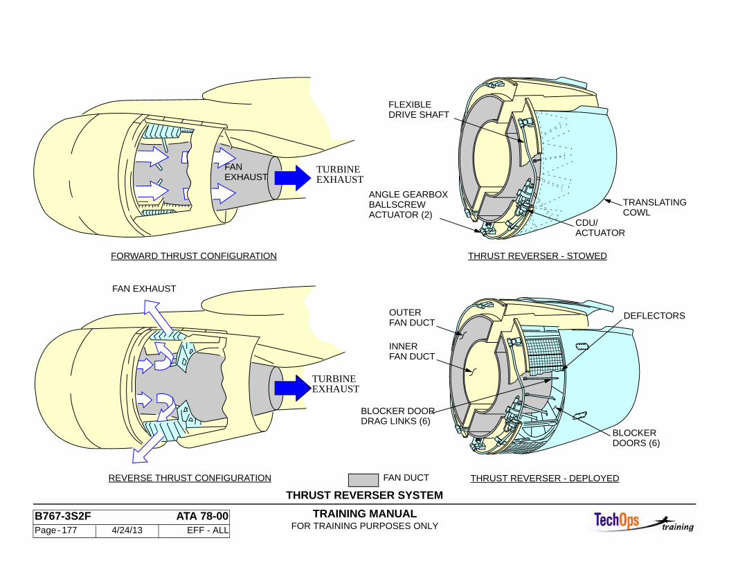
TRAINING MANUALFOR TRAINING PURPOSES ONLY
B767-3S2F ATA 78-00 Page - 177 4/24/13 EFF - ALL
THRUST REVERSER SYSTEM
OUTERFAN DUCT
INNERFAN DUCT
TRANSLATINGCOWL
DRIVE SHAFTFLEXIBLE
DOORS (6)BLOCKER
BLOCKER DOORDRAG LINKS (6)
DEFLECTORS
BALLSCREWACTUATOR (2)
ANGLE GEARBOX
FANEXHAUST
FORWARD THRUST CONFIGURATION
TURBINEEXHAUST
TURBINEEXHAUST
FAN EXHAUST
REVERSE THRUST CONFIGURATION
THRUST REVERSER - STOWED
THRUST REVERSER - DEPLOYED
ACTUATORCDU/
FAN DUCT
TRAINING MANUALFOR TRAINING PURPOSES ONLY
B767-3S2F ATA 78-00 Page - 178 4/24/13 EFF - ALL
THRUST REVERSER - DEFLECTORS
General
There are 16 deflectors on each thrust reverser half that direct fan air forward when the thrust reverser is deployed. When the reverser is stowed, the translating cowls cover the deflectors. When the reverser is deployed, the blocker doors direct fan air through the deflectors.
The deflectors are made of cast aluminum. The front and rear edges of the deflectors are bolted to the thrust reverser fixed structure. There are gang channels between the deflectors to interconnect the deflectors. The gang channels are screwed to the deflectors. The top deflector has two gang channels.
Five different types of deflectors are mounted on each thrust reverser half. Each type directs the air differently. Deflectors are also called cascade segments or cascade vane segments.
Maintenance Practices
Thrust reverser deflectors are not interchangeable because of the different flow angles. Exact deflector position is found in the maintenance manual.
Deflectors must be inspected periodically for cracks, corrosion, and impact damage.
CAUTION: DO NOT OPERATE ENGINE IN REVERSE THRUST WITH DEFLECTORS MISSING. DAMAGE TO THE REVERSER MAY RESULT.
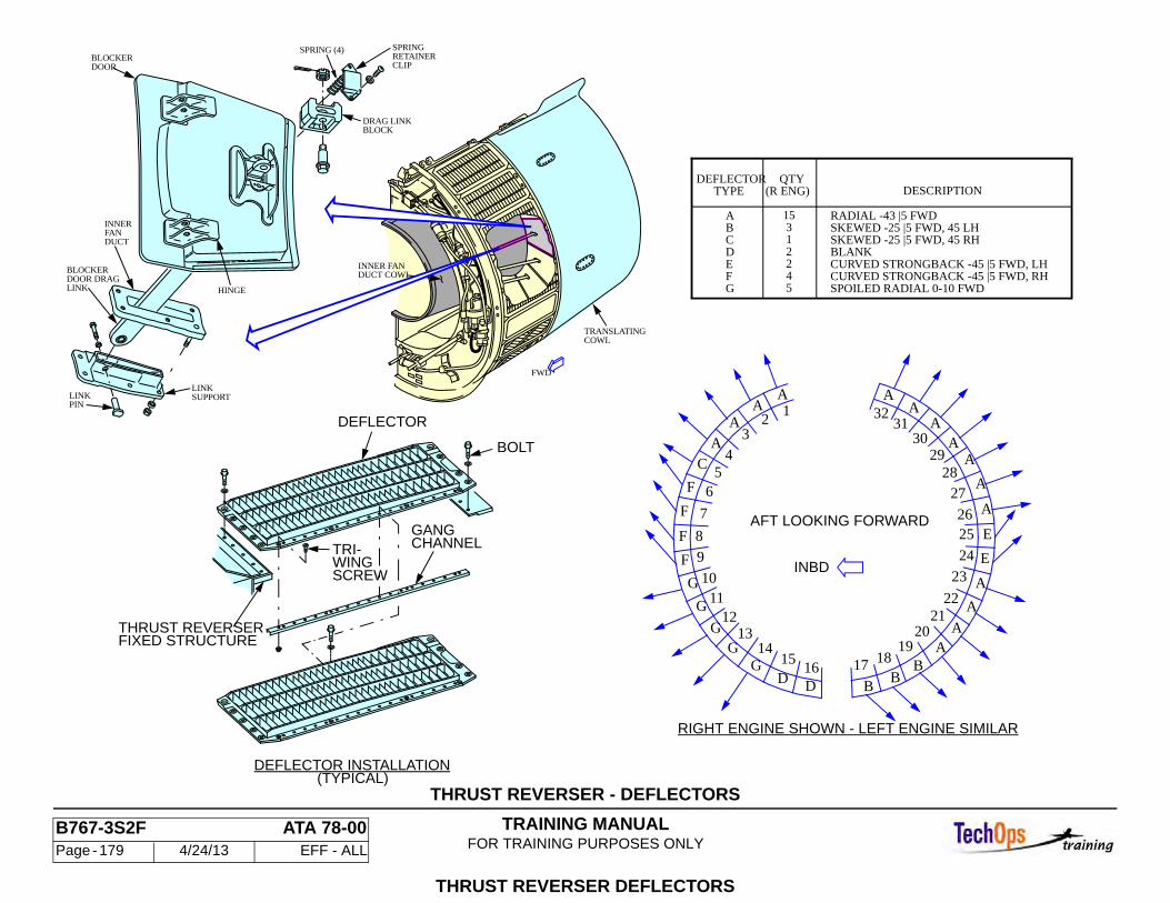
TRAINING MANUALFOR TRAINING PURPOSES ONLY
B767-3S2F ATA 78-00 Page - 179 4/24/13 EFF - ALL
THRUST REVERSER - DEFLECTORS
THRUST REVERSER DEFLECTORS
THRUST REVERSERFIXED STRUCTURE
DEFLECTOR INSTALLATION(TYPICAL)
TRI-WINGSCREW
CHANNELGANG
DEFLECTOR
BOLT
DEFLECTOR
RADIAL -43 |5 FWDSKEWED -25 |5 FWD, 45 LH
QTYDESCRIPTION(R ENG)TYPE
SPOILED RADIAL 0-10 FWD
CURVED STRONGBACK -45 |5 FWD, LHCURVED STRONGBACK -45 |5 FWD, RH
BLANKSKEWED -25 |5 FWD, 45 RH
15 3 1 2 2 4 5
DC
AB
EFG
INBD
AA
AA
A
A
AA
AA
D
12
34
56
7
8
9
1011
1213
1415
16B
B
AA
A
A
A
3132
3029
2827
2625
24
23
2221
2019
1817
C
F
F
F
F
G
G
GG
GD
B
E
E
RIGHT ENGINE SHOWN - LEFT ENGINE SIMILAR
AFT LOOKING FORWARD
INNER FANDUCT COWL
TRANSLATINGCOWL
DRAG LINK
LINK
BLOCK
SUPPORT
SPRING (4)BLOCKERDOOR
BLOCKERDOOR DRAGLINK HINGE
SPRINGRETAINERCLIP
LINKPIN
INNERFANDUCT
FWD
TRAINING MANUALFOR TRAINING PURPOSES ONLY
B767-3S2F ATA 78-00 Page - 180 4/24/13 EFF - ALL
THRUST REVERSER - THRUST REVERSER SYSTEM OPERA-TION
General
Thrust reversers are used by the flight crew to decelerate the airplane immediately after landing or during a refused takeoff. Normal thrust reverser operation requires that the airplane be on the ground, engine running, fire switch in normal, and both pneumatic pressure and electrical power be available.
Deploy
When reverser deployment is commanded, switch and relay logic provide power to unlock the electro-mechanical brake, to energize the directional pilot valve and to open the Thrust Reverser Pressure Regulating and Shut Off Valve (T/R PRSOV). Air from the T/R PRSOV flows to the left and right CDUs and to the DPV. An air signal from the DPV to the CDU arms the CDU to the deploy mode. Air motors in the CDUs drive ballscrew actuators attached to the translating cowls. Angle gearbox and ballscrew actuators are attached to the upper and lower ends of the translating cowls. Flexible drive shafts mechanically connect the angle gearbox and ballscrew actuators to the CDUs.
The air motors in the CDUs drive the center ballscrew actuators and the upper and lower flexible drive shafts. The flexible drive shafts then drive the upper and lower angle gearbox and ballscrew actuators. The ballscrews move the translating cowls aft. Blocker doors, pulled by the drag links, rotate from a flush position against the inside of the translating cowl to a position blocking the fan air discharge path. The fan air discharge is redirected forward through the deflectors. Electronic position feedback on each half of the thrust reverser, provided to the EEC allows the throttle interlock solenoid to operate. The crew can then move the reverse thrust levers to the high power position. Engine Operation During the approach to landing, the engine is not permitted to decelerate below flight idle. After touchdown, the engine speed is maintained at flight (high) idle for 5 seconds by a time delay relay on the engine discrete’s card. This allows 5 seconds for the pilot to decide to go around or to use reverse thrust. If the pilot
does neither, after 5 seconds the engine will decelerate to ground (low) idle and the crew will use the airplane brakes to slow down.
Thrust Reverser Indications
When both halves of a thrust reverser are fully deployed, a green REV indication will appear on the upper EICAS display just above the N1 digital display. When both of the translating sleeves are fully stowed there is no REV message shown. When either or both of the translating sleeves are between the fully stowed and fully deployed position, a yellow REV indication appears above the N1 indication. No thrust reverser messages are shown to the flight crew in flight unless there is an actual abnormal in-flight deployment of a thrust reverser. Then the yellow or green REV indication could be observed.
After the airplane has been on the ground for 60 seconds, faults in the thrust reverser system detected in-flight will illuminate the REV ISLN light and cause the EICAS advisory and latched maintenance message "L (R) REV ISLN VAL" to be displayed.
Thrust Reverser Relay Module
The thrust reverser relay module (M1987) (located in the main equipment center) monitors operation of the thrust reverser system. If in-flight faults lasting more than 5 seconds occur, magnetically latched relays will illuminate light emitting diode indication lights on the module's front panel. The thrust reverser relay module provides fault indications for both engines. It incorporates a self test and a lamp test capability.
Stow
When the thrust reverser is commanded to stow, air from the T/R PRSOV flows to the left and right CDUs and the DPV. Now the DPV remains closed, blocking the air signal to the CDUs. This arms the CDUs to the stow mode. The air motors reverse direction, driving the actuators and translating cowl forward to the stow position. The blocker doors (pushed by the drag links) rotate back to a flush position with the inner translating cowl. When fully stowed, the system de-energizes the solenoids on the electro-mechanical brakes. The system is now locked in the stowed position by the CDU cone brakes and by the electro-mechanical brakes.
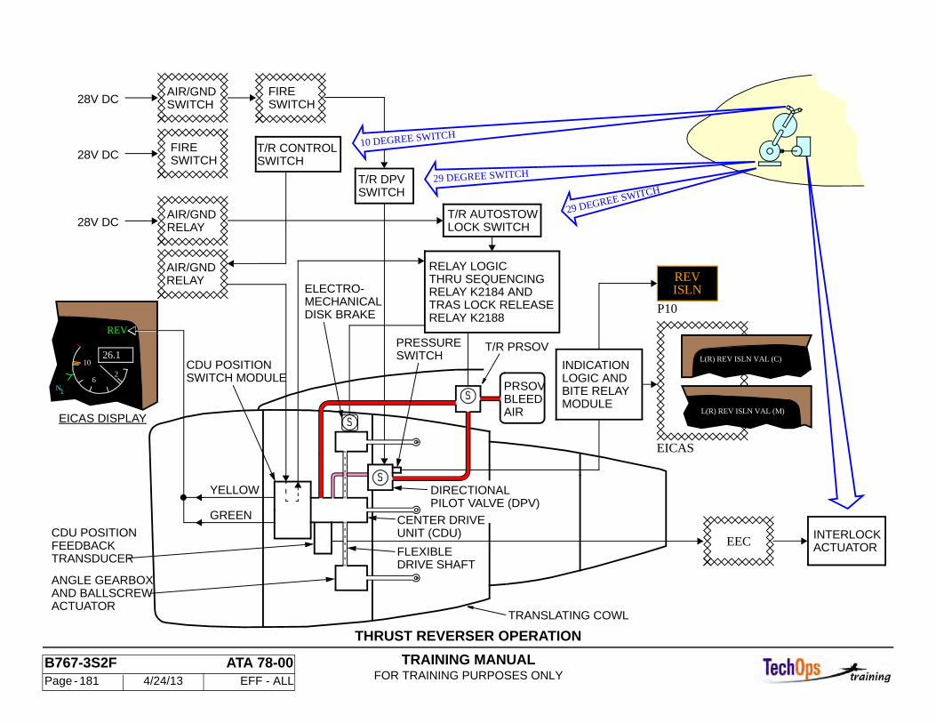
TRAINING MANUALFOR TRAINING PURPOSES ONLY
B767-3S2F ATA 78-00 Page - 181 4/24/13 EFF - ALL
THRUST REVERSER OPERATION
EICAS DISPLAY
SWITCHAIR/GND
SWITCHFIRE
28V DC
EICAS
INDICATIONLOGIC ANDBITE RELAYMODULE
SWITCH MODULECDU POSITION
ANGLE GEARBOXAND BALLSCREWACTUATOR
FEEDBACKTRANSDUCER
CDU POSITION
DRIVE SHAFT
GREEN
YELLOW
FLEXIBLE
SWITCHFIRE
SWITCHT/R CONTROL
28V DC
28V DCAIR/GNDRELAY
SWITCHT/R DPV
AIR/GND
ISLNREV
P10
ACTUATORINTERLOCK
RELAY
DIRECTIONALPILOT VALVE (DPV)
T/R PRSOV
AIRBLEEDPRSOV
CENTER DRIVEUNIT (CDU)
EEC
TRANSLATING COWL
T/R AUTOSTOWLOCK SWITCH
ELECTRO-MECHANICALDISK BRAKE
PRESSURESWITCH
RELAY LOGICTHRU SEQUENCINGRELAY K2184 ANDTRAS LOCK RELEASERELAY K2188
L(R) REV ISLN VAL (M)
L(R) REV ISLN VAL (C)
N
10
62
1
REV
26.1
10 DEGREE SWITCH
29 DEGREE SWITCH
29 DEGREE SWITCH
TRAINING MANUALFOR TRAINING PURPOSES ONLY
B767-3S2F ATA 78-00 Page - 182 4/24/13 EFF - ALL
THRUST REVERSER THRUST REVERSER CONTROL SWITCHES
Three thrust reverser control switches control the electrical signals to deploy or stow the thrust reverser. The control switches are in the pilot's control stand (P8). One switch, in the forward thrust lever handle, controls the signal to the T/R PRSOV. The other two switches, in the micro-switch pack assembly, control the signals to the electro-mechanical brakes (TRAS brakes) and to the DPV.
The T/R PRSOV switch closes when the reverse thrust lever is raised more than 10 degrees. The DPV control switch closes when the reverser thrust lever is raised above 29 degrees. This signals the directional pilot valve to open, directing air to the DEPLOY side of the CDU air motor. At 29 degrees the TRAS lock switch closes, providing power to several relays which unlock the electro-mechanical brakes and signal the T/R PRSOV to open.
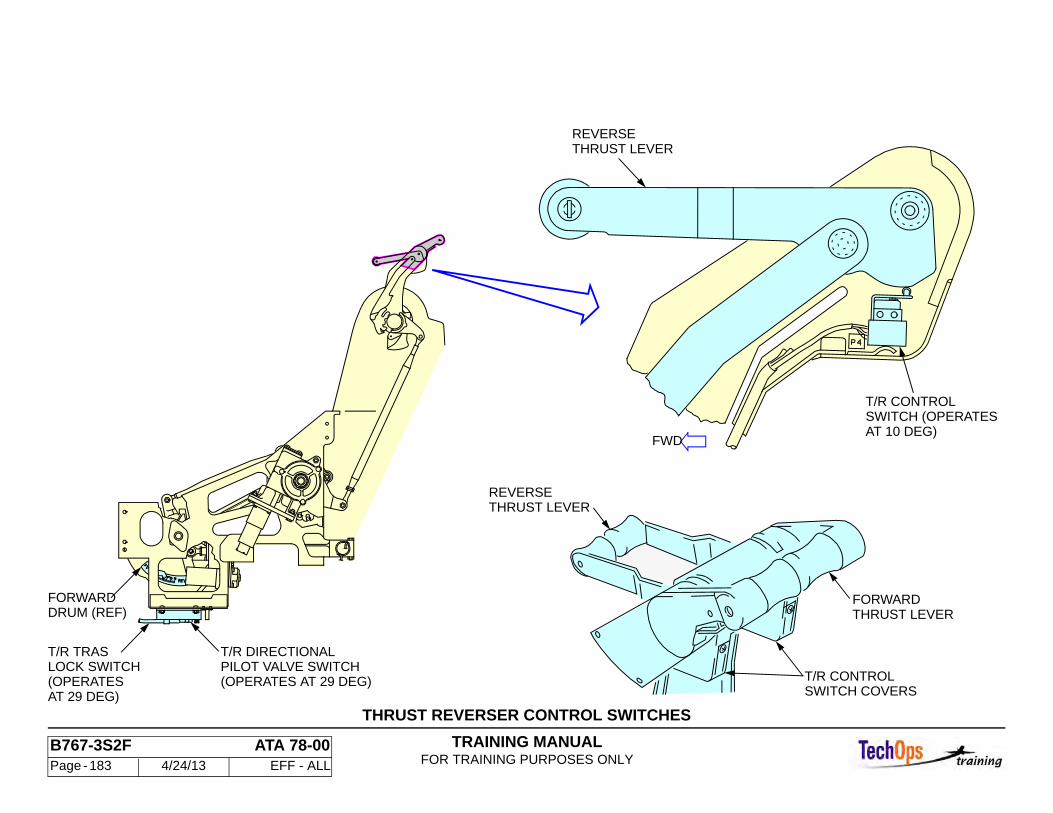
TRAINING MANUALFOR TRAINING PURPOSES ONLY
B767-3S2F ATA 78-00 Page - 183 4/24/13 EFF - ALL
THRUST REVERSER CONTROL SWITCHES
(OPERATES AT 29 DEG)PILOT VALVE SWITCHT/R DIRECTIONAL
(OPERATESLOCK SWITCHT/R TRAS
THRUST LEVERREVERSE
THRUST LEVERFORWARD
DRUM (REF)FORWARD
T/R CONTROL
SWITCH COVERST/R CONTROL
SWITCH (OPERATESAT 10 DEG)
THRUST LEVERREVERSE
FWD
AT 29 DEG)
TRAINING MANUALFOR TRAINING PURPOSES ONLY
B767-3S2F ATA 78-00 Page - 184 4/24/13 EFF - ALL
THRUST REVERSER - ELECTRO-MECHANICAL (TRAS) BRAKE
General
The electro-mechanical brakes (also called the thrust reverser actuation system or "TRAS" brake) provide a third level of safety to prevent uncommanded deployment of the thrust reversers in flight. (The auto stow system, the locking center drive units, and the TRAS brakes provide three levels of safety.) The brake mechanism has a separate, dedicated electrical circuit for its control that is independent of other thrust reverser components.
Description
There are two electro-mechanical brakes installed on each engine, one on each thrust reverser half. The brakes are mounted on brackets attached to the fan reverser torque boxes. Each brake is connected to its upper angle gearbox by a flexible drive shaft. The electro-mechanical brakes are solenoid activated disk brakes. When 28VDC is applied to the brake solenoids, the brakes will release to permit thrust reverser operation. These brakes lock their reverser half by locking the flex drive cable at the upper actuator.
Operation
The electro-mechanical brake (TRAS lock) is spring loaded to the fully braked position. Dual rotors contacting stators provide the braking force friction. To release the brake, the solenoid is energized by electrical current from the thrust reverser actuation system relays and switches. This solenoid force acts against the springs to reduce the rotor/stator friction force, thus releasing the brake.
A manual lockout lever is mounted to the upper surface of the brake. Lifting of this lever will cause an internal cam to act against the springs to reduce the rotor/stator friction force, thus releasing the brake. The lockout lever is used during manual extension of the translating cowl for maintenance and rigging of the thrust reverser. The lockout manual release handle will automatically be returned to the brake position when the fan cowl is closed.
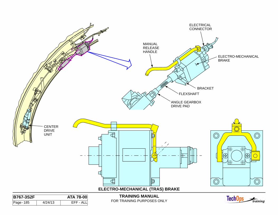
TRAINING MANUALFOR TRAINING PURPOSES ONLY
B767-3S2F ATA 78-00 Page - 185 4/24/13 EFF - ALL
ELECTRO-MECHANICAL (TRAS) BRAKE
FLEXSHAFT
ELECTRICALCONNECTOR
ANGLE GEARBOXDRIVE PAD
BRACKET
MANUAL
HANDLEELECTRO-MECHANICALBRAKE
CENTERDRIVEUNIT
RELEASE
TRAINING MANUALFOR TRAINING PURPOSES ONLY
B767-3S2F ATA 78-00 Page - 186 4/24/13 EFF - ALL
THRUST REVERSER PRESSURE REGULATING VALVE
Pressure Regulating and Shutoff Valve (T/R PRSOV)
The thrust reverser (T/R) pressure regulating and shutoff valve (PRSOV) isolates the thrust reverser pneumatic system from the airplane pneumatic system, and regulates the pressure.
There is one valve in each strut at the entrance to the reverser supply duct downstream of the pre-cooler. Access is through a pressure relief door on the right side of the strut. The T/R PRSOV has a steel valve body with a poppet valve, a solenoid valve, a pressure regulator, and a relief valve.
T/R PRSOV Operation
The poppet valve is spring-loaded closed. When reverse thrust is selected, the solenoid valve is energized. Air flows around the poppet valve stem, through the solenoid valve, and pressurizes the pneumatic actuator. This opens the poppet valve. The pressure regulator opens when the inlet pressure is higher than 70 psig. This modulates the poppet valve, regulating downstream pressure. Normally, the air supply pressure is not high enough to require valve regulation. However, the engine may develop enough 8th stage bleed pressure to open the regulator during a rejected takeoff. The relief valve opens if actuator pressure exceeds 150 psig.
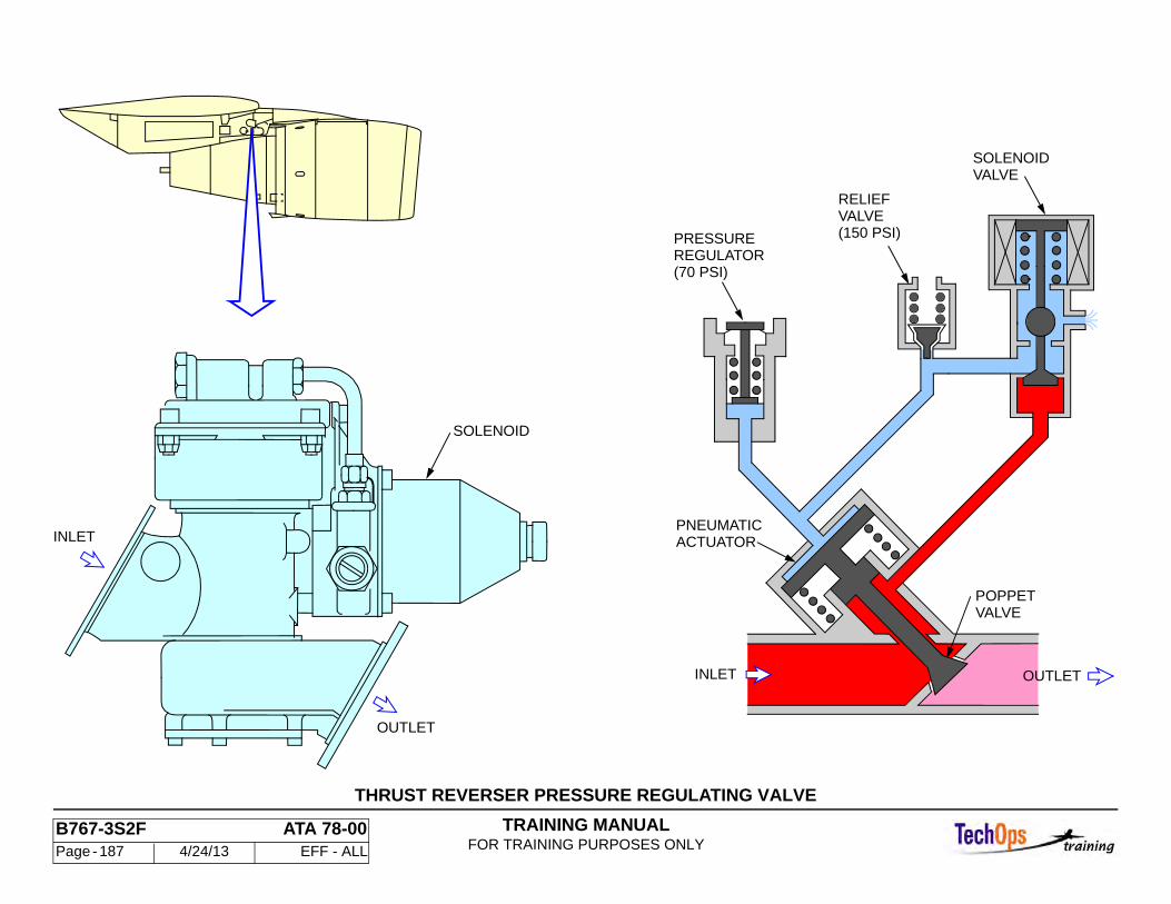
TRAINING MANUALFOR TRAINING PURPOSES ONLY
B767-3S2F ATA 78-00 Page - 187 4/24/13 EFF - ALL
THRUST REVERSER PRESSURE REGULATING VALVE
OUTLET
SOLENOID
INLET ACTUATORPNEUMATIC
VALVESOLENOID
VALVERELIEF
REGULATORPRESSURE
VALVEPOPPET
OUTLETINLET
(70 PSI)
(150 PSI)
TRAINING MANUALFOR TRAINING PURPOSES ONLY
B767-3S2F ATA 78-00 Page - 188 4/24/13 EFF - ALL
DIRECTIONAL PILOT VALVE
General
The directional pilot valve (DPV) is a solenoid controlled pressure operated valve. Switch and relay logic control the solenoid. Air pressure is supplied when the T/R PRSOV is open.
When the DPV is open, it provides air pressure to both halves of the thrust reverser for that engine. This air pressure, called signal air, operates on a piston within each of the CDUs.
The result of the piston motion is to change the position of the directional control valve (DCV) in each CDU. The main flow of air from the T/R PRSOV into the air motor is determined by the position of the DCV. The air motor direction of rotation is reversed as the position of the DCV is changed. One direction of motor rotation moves the sleeves to the deployed position. The opposite direction of air motor rotation moves the sleeves to the stow position. The operation of the air motor and the DCV is discussed later.
The DPV pressure switch completes a circuit for thrust reverser indication.The DPV and pressure switch are on the torque box of the left reverser half. There is one on each engine. Access is through the left fan cowl panel.The DPV is spring-loaded closed. It has a ball and poppet valve on a common shaft, a solenoid, and a cleanable air filter. The pressure switch is a two-position microswitch.
Operation
When reverse thrust is selected, the solenoid is energized and the ball valve moves down and closes the vent. The poppet valve opens to let air pressure from the T/R PRSOV go to the directional control valve.
When the thrust reverser system is in the stow position, the solenoid is de-energized. Air pressure from the T/R PRSOV is blocked. The signal air lines to both CDU directional control valves are vented through the DPV ball valve to ambient.
The pressure switch senses air pressure to the DPV. It is open when the T/R PRSOV is closed. The pressure switch closes when it senses pressure from
the T/R PRSOV. Its position is independent of the directional pilot valve position. There is an indication in the flight compartment if the pressure switch position disagrees with the T/R PRSOV position. This indication is discussed later.
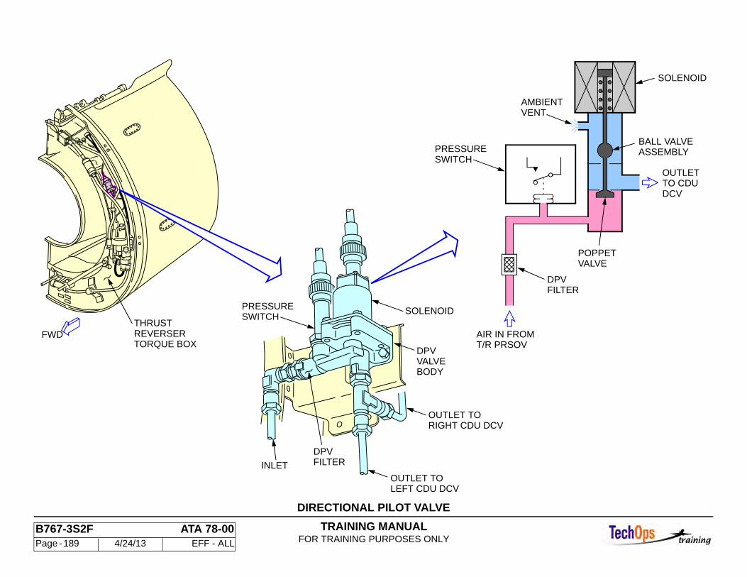
TRAINING MANUALFOR TRAINING PURPOSES ONLY
B767-3S2F ATA 78-00 Page - 189 4/24/13 EFF - ALL
DIRECTIONAL PILOT VALVE
FILTERDPV
DCVTO CDUOUTLET
SOLENOID
BALL VALVEASSEMBLY
SWITCHPRESSURE
VENTAMBIENT
DPVFILTER
POPPETVALVE
LEFT CDU DCV
RIGHT CDU DCV
SOLENOID
DPVVALVEBODY
PRESSURESWITCH
OUTLET TO
OUTLET TO
INLET
FWDTHRUSTREVERSERTORQUE BOX
AIR IN FROMT/R PRSOV
TRAINING MANUALFOR TRAINING PURPOSES ONLY
B767-3S2F ATA 78-00 Page - 190 4/24/13 EFF - ALL
THRUST REVERSER - CENTER DRIVE UNIT
General
The center drive unit (CDU) is a pneumatic motor with a ballscrew actuator for deploying and stowing the thrust reverser. The CDU has a position switch module, a gearbox and a position feedback rod assembly. The gearbox has two flexible drive shaft output drives and a manual drive pad. A Directional Control Valve (DCV) includes a directional valve, a helix rod and spring, and a valve actuator piston. The DCV is spring-loaded in the stow position. The actuator cone brake has a spring-loaded friction cone and rotating mating cone mounted on the air motor shaft. The valve actuator piston moves a pivoted lever to release the brake. When the brake is engaged, the air motor can rotate in the stow direction, but not in the deploy direction.
The ballscrew and ballnut actuator is one assembly. The air motor turns the ballscrew. The ballscrew is free to rotate, but can not translate. It engages the ballnut actuator. The ballnut actuator is free to translate but can not rotate because it is attached to the translating cowl.
The stop rod is linked to the DCV assembly on one end and has a mushroom shaped head on the other. It turns the DCV through an override linkage, operates the CDU position indicating switch assembly, and keeps the cone brake from engaging until the cowl is completely stowed. The CDU position indicating switch assembly has stow and deploy limit switches to indicate thrust reverser position. The switches also control electrical power to the T/R PRSOV. They are operated by the stop rod.
Deploy Operation
Air from the DPV moves the valve actuator piston to the DEPLOY position. The helix rod turns the DCV as the valve actuator piston moves. The piston and pivoted lever release the cone brake, and the air motor rotates turning the ballscrew in the deploy direction. The ballnut and ballscrew actuator move the translating cowl to the deploy position. The stop rod is pulled toward the deploy stop as the actuator approaches fully deployed. At about 1.5 inches from full deploy, the stop rod touches the ballnut.
The stop rod then moves the DCV to the neutral position to stop airflow to the air motor, and engage the cone brake. The stop rod also activates the switches in the CDU position indicating switch module. This causes the T/R PRSOV to close and controls indication of thrust reverser position.
Stow Operation
The air signal from the DPV stops when the stow mode is selected. The spring in the DCV assembly drives the valve actuator piston and moves the DCV to the stow direction. The directional valve override linkage lets the valve turn without the stop rod moving. Air is admitted to the air motor. The ballscrew turns and the ballnut and ballscrew actuator begin moving toward stow. When the actuator is about .25 inch from fully stowed, the stop rod moves the DCV toward neutral. When closed, the DCV has bleed air holes which allows air to drive the CDU to the full stow stop to pre-load the actuation system.
Removal
Remove middle actuator access panel. Manually deploy the thrust reverser half about 6-8 inches until the ballscrew actuator clevis pin is exposed. Deactivate the thrust reverser by reversing the lockout plate. Loosen the retaining clip bolt. Rotate clip and remove clevis pin using a pin extracting tool.
CAUTION: DO NOT REMOVE CLEVIS PIN RETAINING CLIP BOLT. BACK BOLT OUT ENOUGH TO ROTATE RETAINING CLIP. REMOVAL OF BOLT WILL DAMAGE NUTPLATE.
Disconnect the feedback cable and the rotary flexible drive shafts. Remove the 4 CDU flange bolts. Ensure that the CDU upper flexible drive shaft does not slide out of the sheath. Pull CDU and ballscrew actuator from torque box noting shim installation details. Mark the position of the actuator on the ballscrew to aid CDU installation.
Note: Be sure to reference the aircraft M/M when ever you perform any maintenance operation.
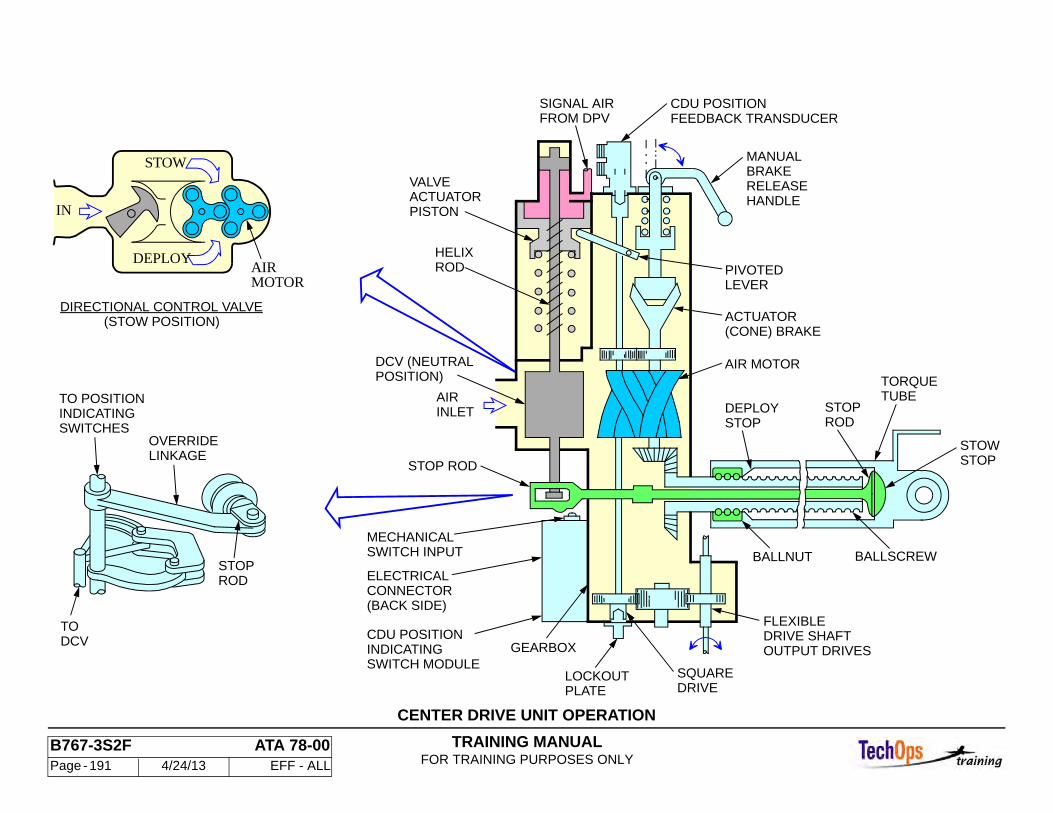
TRAINING MANUALFOR TRAINING PURPOSES ONLY
B767-3S2F ATA 78-00 Page - 191 4/24/13 EFF - ALL
CENTER DRIVE UNIT OPERATION
INDICATINGSWITCHES
TO POSITION
DCV
ROD
OVERRIDELINKAGE
STOP
TO
AIR
INLETAIR
SWITCH MODULEINDICATINGCDU POSITION
(BACK SIDE)CONNECTORELECTRICAL
PLATELOCKOUT
GEARBOX
SWITCH INPUTMECHANICAL
POSITION)DCV (NEUTRAL
FROM DPVSIGNAL AIR
PISTONACTUATORVALVE
RODHELIX
STOP ROD
DRIVESQUARE
BALLNUT
OUTPUT DRIVESDRIVE SHAFTFLEXIBLE
HANDLERELEASEBRAKE
(CONE) BRAKEACTUATOR
LEVERPIVOTED
AIR MOTOR
STOPDEPLOY
BALLSCREW
RODSTOP
TUBETORQUE
STOPSTOW
MANUAL
CDU POSITIONFEEDBACK TRANSDUCER
DIRECTIONAL CONTROL VALVE(STOW POSITION)
DEPLOY
STOW
IN
MOTOR
TRAINING MANUALFOR TRAINING PURPOSES ONLY
B767-3S2F ATA 78-00 Page - 192 4/24/13 EFF - ALL
THRUST REVERSER - ANGLE GEARBOX AND BALLSCREW ACTUATOR
General
Three ballscrew actuators move the translating cowl. One of the ballscrew actuators is driven directly by the CDU. The other two ballscrew actuators are driven by the angle gearboxes. The gearboxes are driven by the CDU through the flexible drive shafts. Access is through the fan cowl. Each gearbox has two square input drives to connect a rotary flexible drive shaft and to permit manual operation, and a splined output for the ballscrew actuator connection. The square drive opposite the drive shaft end is capped. This end may also be used to lock the actuator or for rigging. The 0.2 inch drive requires a special tool to fit the hole.
The ballscrew actuator is coupled to the gearbox spline. A stop collar (not shown) is pinned to the end of the ballscrew to limit actuation length. The ballnut and actuator tube translates as the ballscrew turns.
Removal
The angle gearbox and ballscrew actuator must be removed as a unit. The angle gearbox can be separated from the ballscrew actuator after removal. To remove, deploy the translating cowl 6-8 inches to access the ballscrew actuator clevis pin. Remove the flexible drive shaft, then the clevis pin, and finally the gearbox and actuator.
CAUTION: ENSURE THAT THE DRIVE SHAFT CORE DOES NOT SLIDE OUT OF OUTER CASE WHEN REMOVING THE ROTARY FLEXIBLE DRIVE SHAFT.
CAUTION: DO NOT REMOVE THE CLEVIS PIN RETAINING CLIP BOLT. BACK THE BOLT OUT ONLY ENOUGH TO ROTATE THE RETAINING CLIP. THE NUT PLATE WILL BE DAMAGED IF THE BOLT IS REMOVED.
Note: When installing a gearbox and actuator the side plate on the gearbox must be facing inward.
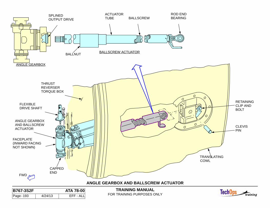
TRAINING MANUALFOR TRAINING PURPOSES ONLY
B767-3S2F ATA 78-00 Page - 193 4/24/13 EFF - ALL
ANGLE GEARBOX AND BALLSCREW ACTUATOR
BALLNUT
BEARINGROD END
OUTPUT DRIVE TUBE
BALLSCREW ACTUATOR
BALLSCREWACTUATORSPLINED
ANGLE GEARBOX
ACTUATOR
ANGLE GEARBOXAND BALLSCREW
NOT SHOWN)(INWARD FACINGFACEPLATE
DRIVE SHAFTFLEXIBLE
CLEVIS
FWD
PIN
CAPPEDEND
TORQUE BOX
THRUST
RETAININGCLIP ANDBOLT
TRANSLATINGCOWL
REVERSER
TRAINING MANUALFOR TRAINING PURPOSES ONLY
B767-3S2F ATA 78-00 Page - 194 4/24/13 EFF - ALL
THRUST REVERSER - ELECTRICAL OPERATION
Operational Description - Electrical Circuits
The electrical control system consists of four switches, four solenoids, two position switches, and eight relays for each thrust reverser. Operation of the left engine thrust reverse will be explained. The operation of the right engine thrust reverser is the same, but the components have different numbers and locations.
Deploy Mode
For an engine thrust reverser deployment the T/R PRSOV, DPV and the two TRAS solenoids all must be energized. To energize the four solenoids, the airplane must be on the ground. With the forward thrust levers at the forward idle position the pilot rotates the reverse thrust lever aft. Rotation of the reverse thrust lever to the rear sequentially closes three switches:
• T/R control switch (S5) • T/R DPV control switch (S11) • TRAS lock switch (S21).
The T/R control switch (S5) is the first to close at approximately 10 degrees of reverse thrust lever rotation.
At approximately 29 degrees of reverse thrust lever rotation the T/R DPV control and the TRAS lock switches close. The DPV solenoid, T/R sequence relay (K2184), and TRAS lock release relay (K2182) are energized; followed by the T/R PRSOV solenoid (V360), the left and right TRAS solenoids, and the T/R unstow relay (K26); and finally the TRAS lock release control relay (K2188).
The proper sequencing of the four controlling solenoids is critical. The DPV solenoid is the first to be energized even though it is controlled by one of the 29× switches. The T/R PRSOV solenoid and the left and right TRAS solenoid are essentially energized simultaneously, however, the TRAS brakes are released prior to pneumatics being available to drive the CDUs. There is approximately a 160 millisecond window between the TRAS brake release and the CDUs spinning up to speed thereby insuring that the TRAS brakes are not released under load. With proper sequencing, the engine thrust reverser, driven by the CDUs, translates to the fully deployed position.
Stow Mode During stow operations, the reverse thrust levers are moved forward and down. There is no stop position between deployed and stowed. The 29× switches open first and then the 10× switch opens. The DPV closes. The T/R PRSOV opens to drive the translating sleeves to the stow position. Position switches signal the T/R PRSOV to close, removing air from the CDUs. Two seconds after removal of the pneumatic operating pressure from the thrust reverser system, the 28 VDC power is removed from the electro-mechanical brake solenoids and the brakes engage again.
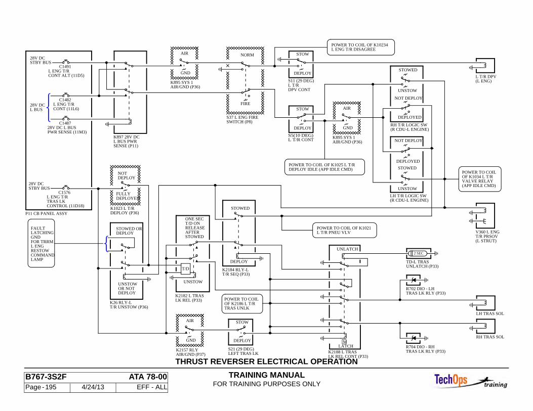
TRAINING MANUALFOR TRAINING PURPOSES ONLY
B767-3S2F ATA 78-00 Page - 195 4/24/13 EFF - ALL
THRUST REVERSER ELECTRICAL OPERATION
POWER TO COIL
(APP IDLE CMD)VALVE RELAYOF K1034 L T/R
DEPLOY IDLE (APP IDLE CMD)POWER TO COIL OF K1025 L T/R
C1576
STOWED ORDEPLOY
RH T/R LOGIC SW
POWER TO COILOF K2186 L T/RTRAS UNLK
T/R SEQ (P33)K2184 RLY-L
DEPLOY
T/R PRSOV(L STRUT)
LH T/R LOGIC SW(R CDU-L ENGINE)
V360 L ENG
AIR/GND (P36)K895 SYS 1
(R CDU-L ENGINE)
STBY BUS28V DC
CONT ALT (11D5)L ENG T/R
C1491
DPV CONT
S11 (29 DEG)
SWITCH (P8)S37 L ENG FIRE
P11 CB PANEL ASSY
28V DCL BUS
PWR SENSE (11M3)28V DC L BUS
C1487
CONT (11L6)L ENG T/R
C1482
SENSE (P11)L BUS PWRK897 28V DC
AIR/GND (P36)K895 SYS 1
S5(10 DEG)
POWER TO COIL OF K10234L ENG T/R DISAGREE
LAMPCOMMANDRESTOWL ENGFOR TRRMGNDLATCHINGFAULT
T/R UNSTOW (P36)K26 RLY-L
STBY BUS28V DC
UNSTOWOR NOTDEPLOY
K2157 RLYAIR/GND (P37)
S21 (29 DEG)
K2182 L TRASLK REL (P33)
(L ENG)L T/R DPV
RH TRAS SOL
LH TRAS SOL
LATCHK2188 L TRASLK REL CONT (P33)
UNLATCH
TRAS LK RLY (P33)R704 DIO - RH
R702 DIO - LHTRAS LK RLY (P33)
2 SEC
TD-L TRASUNLATCH (P33)T/D
UNSTOW
STOWED
POWER TO COIL OF K1021L T/R PNEU VLV
L ENG T/RTRAS LKCONTROL (11D18)
K1023 L T/RDEPLOY (P36)
T/D ONRELEASEAFTERSTOWED
ONE SEC
STOWED
NOT DEPLOY
DEPLOYED
UNSTOW
STOW
AIR
GND
NOT DEPLOY
DEPLOYED
UNSTOW
STOWED
STOW
DEPLOY
NORM
FIRE
AIR
GND
STOW
DEPLOY
AIR
GND DEPLOY
DEPLOYNOT
FULLYDEPLOYED
L T/R CONT
L T/R
LEFT TRAS LK
M
TRAINING MANUALFOR TRAINING PURPOSES ONLY
B767-3S2F ATA 78-00 Page - 196 4/24/13 EFF - ALL
THRUST REVERSER - THRUST REVERSER INDICATING SYS-TEM OPERATION
General
This system gives indications of thrust reverser position and malfunctions. No thrust reverser messages are shown to the flight crew in flight unless there is an actual abnormal in-flight deployment of a thrust reverser. Then the yellow or green REV indication could be observed.
T/R Position Indication
When both halves of a thrust reverser are fully deployed, a green REV indication will appear on the upper EICAS display just above the N1 digital display. When both of the translating sleeves are fully stowed there is no REV indication shown. When either or both of the translating sleeves are between the fully stowed and fully deployed position, a yellow REV indication appears above the N1 indication.
T/R Malfunction Indications
After the airplane has been on the ground for 60 seconds, faults in the thrust reverser system detected in-flight will illuminate REV ISLN light and cause the EICAS advisory and latched maintenance message "L (R) REV ISLN VAL" to be displayed. Appearance of these indications on the ground (the messages and the light are inhibited in-flight by air/ground logic) mean either:
• that the reverser may not deploy when commanded on the ground, or • that the thrust reverser relay module (TRRM) detected and latched an in-
flight fault in the reverser system
Thrust Reverser Relay Module (TRRM)
The thrust reverser relay module (M1987) (located in the main equipment center) monitors operation of the thrust reverser system. If in-flight faults lasting more than 5 seconds should occur, magnetically latched relays will illuminate light emitting diode indication lights on the module's front panel. The thrust
reverser relay module provides fault indications for both engines. It incorporates a self test and a lamp test capability. The thrust reverser relay module only monitors the reverser system while the airplane is in the air mode. It is inhibited on the ground. However, the TRRM can be utilized to monitor the reverser system on the ground to aide troubleshooting by pushing the test enable switch located on the front panel. A reset switch releases the magnetically latched relays to turn off the fault lights. A lamp test switch illuminates all light emitting diodes while pressed.
The thrust reverser relay module will latch a fault if any of the following conditions exist for more than 5 seconds while the airplane is in-flight:
• An unstowed sleeve is detected by the limit switches on the center drive unit. The LED labeled RESTOW COMMAND will be illuminated.
• The electro-mechanical brake solenoids are being commanded to release the brakes due to power being present at the thrust reverser activation system (TRAS) lock release control relay (K2188). The LED labeled TRAS UNLOCK will be illuminated.
• Pneumatic pressure is present downstream of the T/R PROSOV as indicated by the pressure switch mounted on the directional pilot valve. The LED labeled PRSOV PRESSURE will be illuminated.
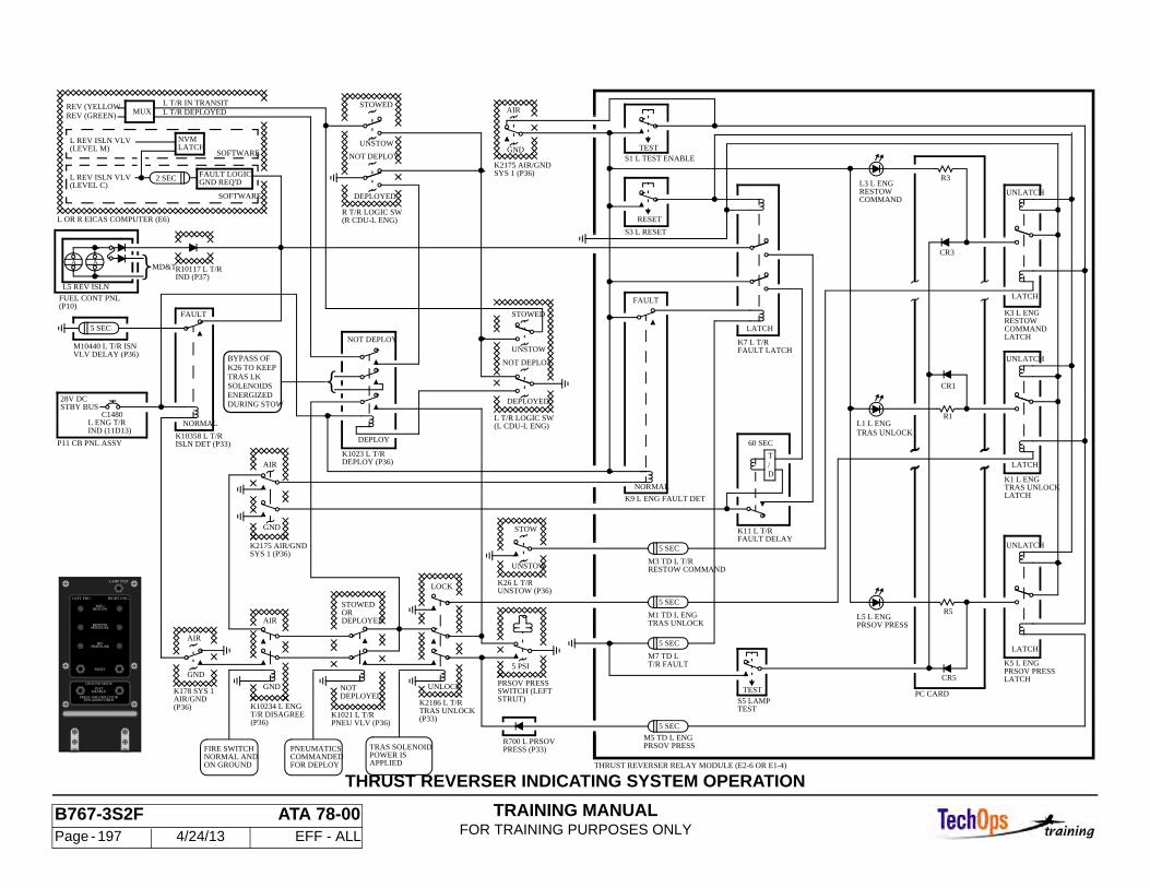
TRAINING MANUALFOR TRAINING PURPOSES ONLY
B767-3S2F ATA 78-00 Page - 197 4/24/13 EFF - ALL
THRUST REVERSER INDICATING SYSTEM OPERATION
GND REQ'D
NOT DEPLOY
(R CDU-L ENG)R T/R LOGIC SW
STOW
UNSTOW
UNSTOW (P36)K26 L T/R
5 SEC
5 SEC
L REV ISLN VLV(LEVEL M)
L REV ISLN VLV(LEVEL C)
UNSTOW
STOWED
DEPLOYED
NOTDEPLOYED
DEPLOYED
STOWEDOR
K1021 L T/RPNEU VLV (P36)
FAULT
MD&T
5 SEC
IND (11D13)L ENG T/R
C1480
K10358 L T/R
28V DCSTBY BUS
MUXREV (YELLOWREV (GREEN)
L T/R IN TRANSIT
NVMLATCH
SOFTWARE
SOFTWARE
L T/R DEPLOYED
L5 REV ISLN
NORMAL
AA
IND (P37)R10117 L T/R
FAULT LOGIC
ISLN DET (P33)
5 PSI
K178 SYS 1AIR/GND(P36)
NOT DEPLOY
SYS 1 (P36)K2175 AIR/GND
UNSTOW
(L CDU-L ENG)L T/R LOGIC SW
DEPLOYED
NOT DEPLOY
STOWED
DEPLOY
DURING STOWENERGIZEDSOLENOIDSTRAS LKK26 TO KEEPBYPASS OF
2 SEC
5 SEC
5 SEC
(P10)FUEL CONT PNL
P11 CB PNL ASSY
DEPLOY (P36)K1023 L T/R
L OR R EICAS COMPUTER (E6)
M10440 L T/R ISNVLV DELAY (P36)
POWER ISTRAS SOLENOID
APPLIED
M3 TD L T/RRESTOW COMMAND
M7 TD LT/R FAULT
FAULT
(P33)
PNEUMATICSCOMMANDEDFOR DEPLOY
K10234 L ENG
(P36)T/R DISAGREE
FIRE SWITCHNORMAL ANDON GROUND
R700 L PRSOVPRESS (P33)
LOCK
STRUT)SWITCH (LEFTPRSOV PRESSUNLOCK
AIR
GND
AIR
SYS 1 (P36)K2175 AIR/GND
M5 TD L ENGPRSOV PRESS
M1 TD L ENGTRAS UNLOCK
TRAS UNLOCK
GND
NORMAL
K2186 L T/R
AIR
GND
AIR
GND
TEST
TESTS5 LAMP
S1 L TEST ENABLE
S3 L RESET
K9 L ENG FAULT DET LATCHTRAS UNLOCKK1 L ENG
LATCH
UNLATCH
LATCH
UNLATCH
K3 L ENG
LATCH
UNLATCH
LATCHCOMMANDRESTOW
LATCH
FAULT LATCHK7 L T/R
COMMANDRESTOWL3 L ENG
RESET
R5
60 SEC
D/T
FAULT DELAYK11 L T/R
CR5
CR1
R1
TEST
PC CARD
THRUST REVERSER RELAY MODULE (E2-6 OR E1-4)
TRAS UNLOCKL1 L ENG
PRSOV PRESSL5 L ENG
LATCHPRSOV PRESSK5 L ENG
CR3
R3
LAMP TEST
PSEU
TEN (10)SECONDS
RESET
PRESS AND HOLD FOR
ENABLETEST
GROUND MODE
RESTOWPRESSURE
RESTOW
HIVPRESSURE
LEFT ENG RIGHT ENG
TRAINING MANUALFOR TRAINING PURPOSES ONLY
B767-3S2F ATA 78-00 Page - 198 4/24/13 EFF - ALL
THRUST REVERSER - TRANSLATING COWL MANUAL DEPLOY/STOW
General
This procedure covers manual cowl translation (deploy or stow) of the translating cowl using either a manual speed wrench or an air-powered wrench. Each cowl is operated independently of the other using this procedure. Do not extend either translating cowl if the thrust reverser is opened more than the 34-degree (first stick) position.
WARNING: YOU MUST CAREFULLY FOLLOW THE INSTRUCTIONS IN THIS TASK. IF YOU DO NOT, THE THRUST REVERSER CAN ACCIDENTLY OPERATE AND CAUSE INJURY TO PERSONS AND DAMAGE TO EQUIPMENT.
WARNING: DO THE DEACTIVATION PROCEDURE FOR THE SPOILER/SPEED BRAKE SYSTEM OR REMOVE ALL PERSONS AND EQUIPMENT AWAY FROM THE SPOILERS. THE SPOILERS CAN RETRACT QUICKLY AND CAUSE INJURIES TO PERSONS AND DAMAGE TO EQUIPMENT. (REF AMM 27-61-00/201)
CAUTION: DO NOT OPEN THE THRUST REVERSER HALF TO MORE THAN THE 34-DEGREE (FIRST STICK) POSITION IF THE TRANSLATING COWL IS EXTENDED. DAMAGE TO THE TRANSLATING COWL OR THE STRUT CAN OCCUR.
CAUTION: MAKE SURE THAT THERE IS NO EQUIPMENT IN THE AREA AFT OF THE THRUST REVERSER. DAMAGE CAN OCCUR IF THE THRUST REVERSER HITS THE EQUIPMENT.
CAUTION: WHEN YOU MANUALLY MOVE THE THRUST REVERSER, LOOK FOR THE TOP AND BOTTOM BALLSCREW ACTUATORS TO TURN. IF YOU DO NOT SEE THESE BALLSCREW ACTUATORS TURN, DO A CHECK FOR FLEXSHAFTS THAT ARE BROKEN OR GONE.
Deploy
Open the applicable circuit breakers on the P11 panel to remove power from the thrust reverser actuation system; install DO-NOT-CLOSE identifiers on the circuit breakers. Deactivate the spoiler/speed brake control system. Insure that the reverse thrust levers are fully forward, and attach a DO-NOT-OPERATE tag. Make sure that a pneumatic source is not connected to the thrust reverser. Open the fan cowl panels. Make sure that the D-shaped pressure relief door is closed and latched. If the thrust reverser is opened to the 34-degree (first stick) position, make sure that the leading edge slats are fully retracted. Pull up on the manual release handle to unlock the electro-mechanical (TRAS lock) brake. Pull the cone brake release handle out and away from the CDU until the detent is felt. Remove the two bolts that attach the lockout plate to the manual drive pad on the bottom of the CDU. Put a 1/4-inch square-drive into the CDU manual drive. Turn the square-drive on the CDU to extend the translating cowl. Less than 10 pound-inches of torque should be applied. Open the other thrust reverser half if it is necessary.
CAUTION: IF YOU USE AN AIR WRENCH TO EXTEND/RETRACT THE TRANSLATING COWL, LOOK FOR MOVEMENT OF THE FEEDBACK ROD WHEN THE TRANSLATING COWL IS ALMOST FULLY EXTENDED/RETRACT. WHEN YOU SEE MOVEMENT, REMOVE THE AIR WRENCH AND FULLY EXTEND/RETRACT THE TRANSLATING COWL WITH A MANUAL WRENCH. THE CDU WILL LOCK IF THE STOPS ARE ENGAGED, AND DAMAGE TO THE CDU CAN OCCUR.
Stow
Prepare the thrust reverser for stowing the thrust reverser as you did for deploying the translating cowl. Put a 1/4-inch square-drive into the CDU manual drive. Turn the square-drive on the CDU to retract the translating cowl. Less than 10 pound-inches of torque should be applied. When the translating cowl is about one inch from the fully retracted position, push the stow rig button on the CDU. Stop turning the CDU when the stow rig pin moves and then starts to move out again. Turn the wrench in the direction that aligns the rig pin plunger with the groove in the CDU actuator. Measure to make sure that the clearance between the torque box and the translating cowl is between 0.060-0.150 inch (1.5-3.8 mm). Restore the airplane to normal.
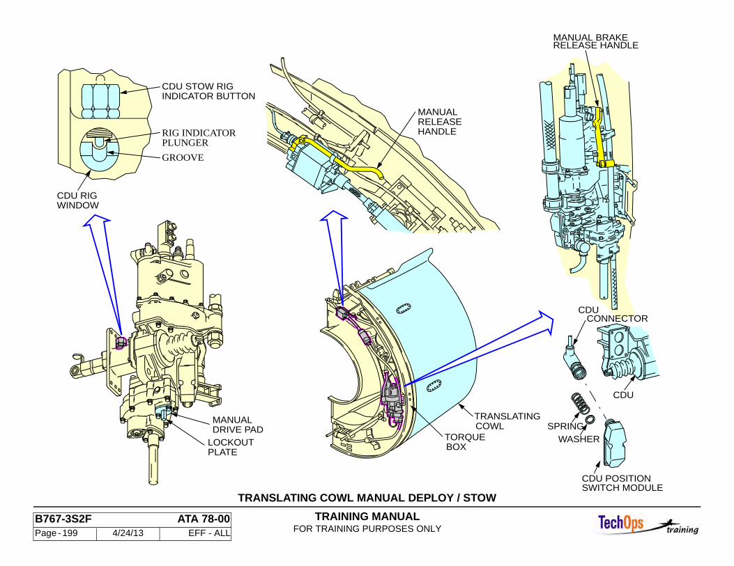
TRAINING MANUALFOR TRAINING PURPOSES ONLY
B767-3S2F ATA 78-00 Page - 199 4/24/13 EFF - ALL
TRANSLATING COWL MANUAL DEPLOY / STOW
SPRING
WASHER
CDU
CDU POSITIONSWITCH MODULE
COWLTRANSLATING
TORQUEBOX
INDICATOR BUTTON
PLUNGERRIG INDICATOR
GROOVE
CDU STOW RIG
WINDOWCDU RIG
HANDLERELEASEMANUAL
CDU
MANUAL BRAKERELEASE HANDLE
DRIVE PADMANUAL
LOCKOUTPLATE
CONNECTOR
TRAINING MANUALFOR TRAINING PURPOSES ONLY
B767-3S2F ATA 78-00 Page - 200 4/24/13 EFF - ALL
THRUST REVERSER - TRANSLATING COWL POWER DEPLOY/STOW USING AIR APPLIED DIRECTLY TO THE CDU
General
This procedure covers power translation of the translating cowl using a ground pneumatic air source connected directly to the CDU. Do not extend a translating cowl with the thrust reverser open beyond the 34-degree (first stick) position.
WARNING: BE SURE TO COMPLY WITH ALL MM WARNINGS, CAUTIONS AND ADVISORIES. FAILURE TO DO SO MAY RESULT IN PERSONAL INJURY OR DAMAGE TO EQUIPMENT.
Deploy
Open the selected circuit breakers on the P11 panel and install DO-NOT-CLOSE identifiers. (see MM) Deactivate the spoiler/speedbrake control system, ensure the reverse thrust levers are in the forward (stow) position, and ensure that the thrust reverser is not open beyond the 34-degree position, ensure that the core cowl panels are removed or closed. Open the fan cowl.
Remove the blue cap opposite the CDU pneumatic supply and connect pneumatic power from a ground air source. Slowly pressurize to 20-30 psig. Remove the DO-NOT-CLOSE identifiers and close the T/R PRSOV circuit breakers. Place the reverse thrust levers to the reverse idle position and allow translating cowl to fully deploy.
Stow Provide pneumatic power and place the reverse thrust lever to forward (stow) position. Allow translating sleeve to fully stow. Reduce pneumatic pressure to zero and disconnect ground pneumatic source. Install, tighten and lockwire the blue cap on the CDU air connection. Ensure the thrust reverser is fully stowed by checking that the gap between the torque box and the translating cowl is 0.060 - 0.150 inch at the center drive unit. Return the aircraft to normal.
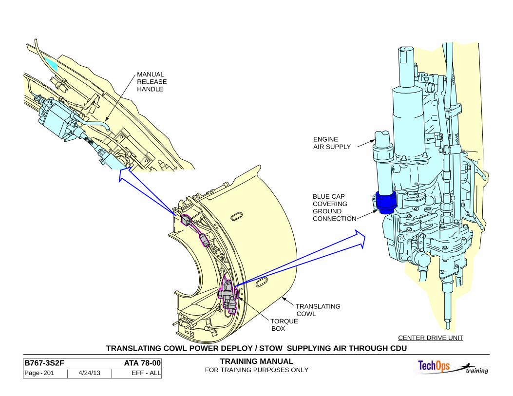
TRAINING MANUALFOR TRAINING PURPOSES ONLY
B767-3S2F ATA 78-00 Page - 201 4/24/13 EFF - ALL
TRANSLATING COWL POWER DEPLOY / STOW SUPPLYING AIR THROUGH CDU
HANDLERELEASEMANUAL
COWLTRANSLATING
TORQUEBOX
ENGINEAIR SUPPLY
BLUE CAPCOVERING
CONNECTIONGROUND
CENTER DRIVE UNIT

TRAINING MANUALFOR TRAINING PURPOSES ONLY
B767-3S2F ATA 78-00 Page - 202 4/24/13 EFF - ALL
THRUST REVERSER - TRANSLATING COWL DEPLOY / STOW WITH GROUND SERVICE SWITCH
General
This procedure covers power translation of the thrust reverser translating sleeve using air from the opposite engine, external pneumatics connection or the APU. This air in the pneumatic system normally can not back-flow through the Engine PRSOV to the T/R PRSOV. This process electronically opens the PRSOV using the ground service switch. This is a guarded switch, spring loaded to the “OFF” position that is located next to the engine oil tank.
WARNING: BE SURE TO COMPLY WITH ALL M/M WARNINGS, CAUTIONS, AND ADVISORIES. FAILURE TO DO SO MAY RESULT IN PERSONAL INJURY OR DAMAGE TO EQUIPMENT.
Refer to the applicable MM for Spoiler / Speedbrake deactivation. Inadvertent spoiler movement caused by actuating thrust levers could result in serious injury to personnel. Ensure reverse thrust levers are in the forward thrust (stowed) position and thrust reverser control circuit breakers are opened. Injury to personnel and or damage to equipment could occur when providing external pneumatic power. Thrust reversers will move when the T/R lever is moved to the reverse thrust position. Ensure area aft of the T/R is clear of personnel and equipment before operating the thrust reverser.
Note: With pneumatic power provided, a deployed thrust reverser will stow if electrical power is lost to the directional pilot valve.
WARNING: WHEN MAINTENANCE IS PERFORMED ON OR NEAR THE T/R THE SYSTEM SHOULD BE LOCKED OUT PER THE MM.
Deploy
Open the selected T/R circuit breakers on the P11 panel and install “DO NOT CLOSE” identifiers. Deactivate the spoiler speed brakes. Ensure the thrust reverser levers are in the forward thrust position (stowed). Ensure T/R is not open beyond the 34 degree position, and that the core cowl panels are removed or closed. Open the fan cowl panels. Provide pneumatic power to the airplane per MM. Push the applicable L or R ENG OFF switch lights on the air supply
module on the P5 panel to the open position. Remove the “DO NOT CLOSE” identifiers and close the T/R PRSOV circuit breakers. Place the reverse thrust levers to the reverse idle position. Lift the guard on the PRSOV ground service switch. Push the switch to the up position and hold it. Allow the translating cowls to fully deploy before releasing the switch.
Stow
Provide pneumatic power. Push the applicable “L or R ENG OFF” switch light on the air supply module on the P5 panel to the open position and place the reverse thrust lever to the forward position (stowed). Lift the guard on the PRSOV ground service switch and push the switch up. Hold the switch until the T/R is fully stowed. Release the ground service switch. Ensure the T/R is fully stowed by checking the gap between the torque box and the translating cowl is between 0.060 and 0.150 inch at the CDU. Return the aircraft to normal configuration.
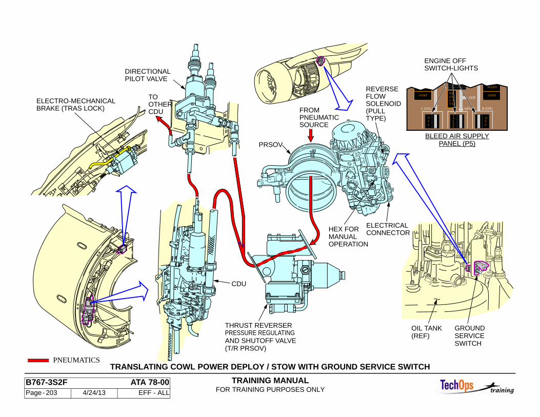
TRAINING MANUALFOR TRAINING PURPOSES ONLY
B767-3S2F ATA 78-00 Page - 203 4/24/13 EFF - ALL
TRANSLATING COWL POWER DEPLOY / STOW WITH GROUND SERVICE SWITCH
OIL TANK(REF)
GROUNDSERVICESWITCH
ELECTRO-MECHANICALBRAKE (TRAS LOCK)
PNEUMATICS
FROMPNEUMATICSOURCE
PRSOV
ELECTRICALCONNECTOR
REVERSEFLOWSOLENOID(PULLTYPE)
HEX FORMANUALOPERATION
CDU
PRESSURE REGULATINGAND SHUTOFF VALVE(T/R PRSOV)
THRUST REVERSER
DIRECTIONALPILOT VALVE
CDU
TOOTHER
PANEL (P5)BLEED AIR SUPPLY
SWITCH-LIGHTSENGINE OFF
OVHTOVHT
L ENGa
FFO
E
LV
AV
FFO
KTACEULD
APU
ADP
R ENG
BLEED
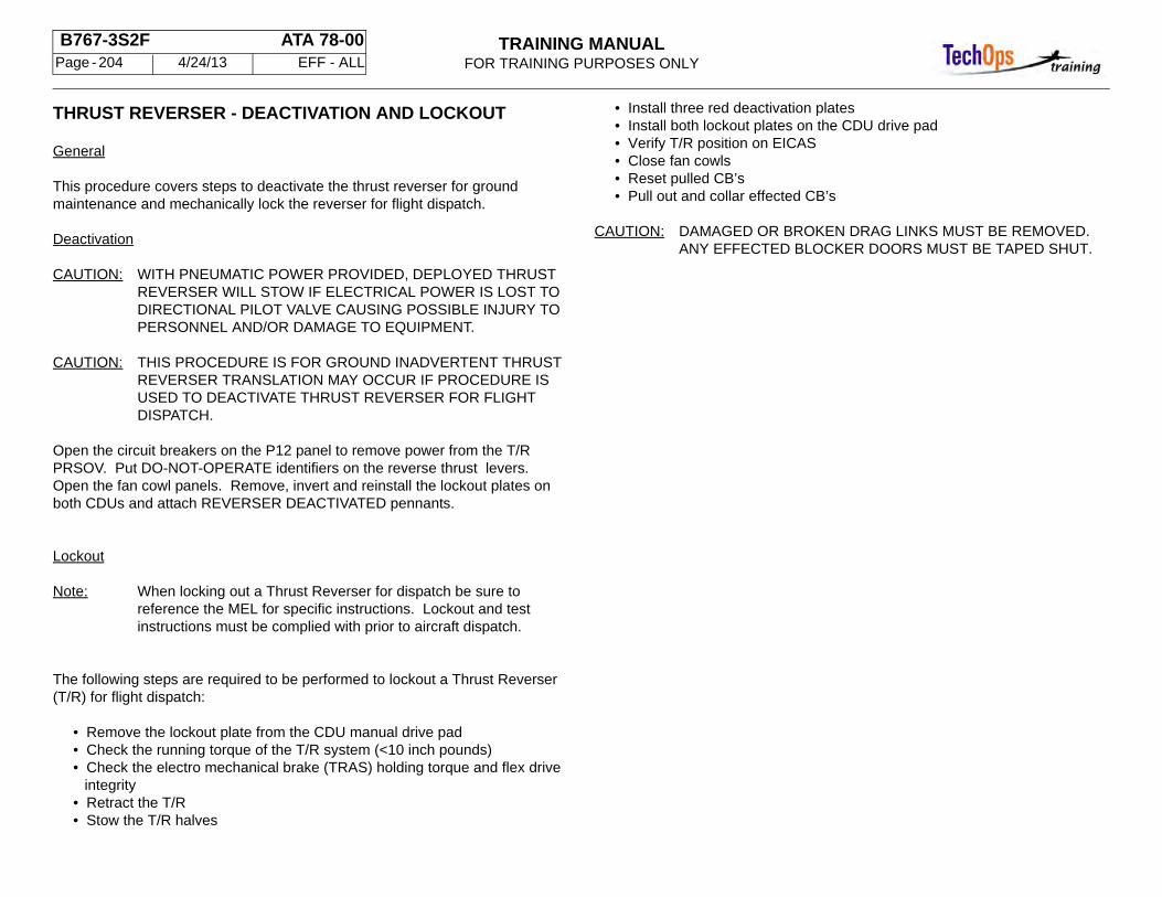
TRAINING MANUALFOR TRAINING PURPOSES ONLY
B767-3S2F ATA 78-00 Page - 204 4/24/13 EFF - ALL
THRUST REVERSER - DEACTIVATION AND LOCKOUT
General
This procedure covers steps to deactivate the thrust reverser for ground maintenance and mechanically lock the reverser for flight dispatch.
Deactivation
CAUTION: WITH PNEUMATIC POWER PROVIDED, DEPLOYED THRUST REVERSER WILL STOW IF ELECTRICAL POWER IS LOST TO DIRECTIONAL PILOT VALVE CAUSING POSSIBLE INJURY TO PERSONNEL AND/OR DAMAGE TO EQUIPMENT.
CAUTION: THIS PROCEDURE IS FOR GROUND INADVERTENT THRUST REVERSER TRANSLATION MAY OCCUR IF PROCEDURE IS USED TO DEACTIVATE THRUST REVERSER FOR FLIGHT DISPATCH.
Open the circuit breakers on the P12 panel to remove power from the T/R PRSOV. Put DO-NOT-OPERATE identifiers on the reverse thrust levers. Open the fan cowl panels. Remove, invert and reinstall the lockout plates on both CDUs and attach REVERSER DEACTIVATED pennants.
Lockout
Note: When locking out a Thrust Reverser for dispatch be sure to reference the MEL for specific instructions. Lockout and test instructions must be complied with prior to aircraft dispatch.
The following steps are required to be performed to lockout a Thrust Reverser (T/R) for flight dispatch:
• Remove the lockout plate from the CDU manual drive pad • Check the running torque of the T/R system (<10 inch pounds) • Check the electro mechanical brake (TRAS) holding torque and flex drive
integrity • Retract the T/R • Stow the T/R halves
• Install three red deactivation plates • Install both lockout plates on the CDU drive pad • Verify T/R position on EICAS • Close fan cowls • Reset pulled CB’s • Pull out and collar effected CB’s
CAUTION: DAMAGED OR BROKEN DRAG LINKS MUST BE REMOVED. ANY EFFECTED BLOCKER DOORS MUST BE TAPED SHUT.
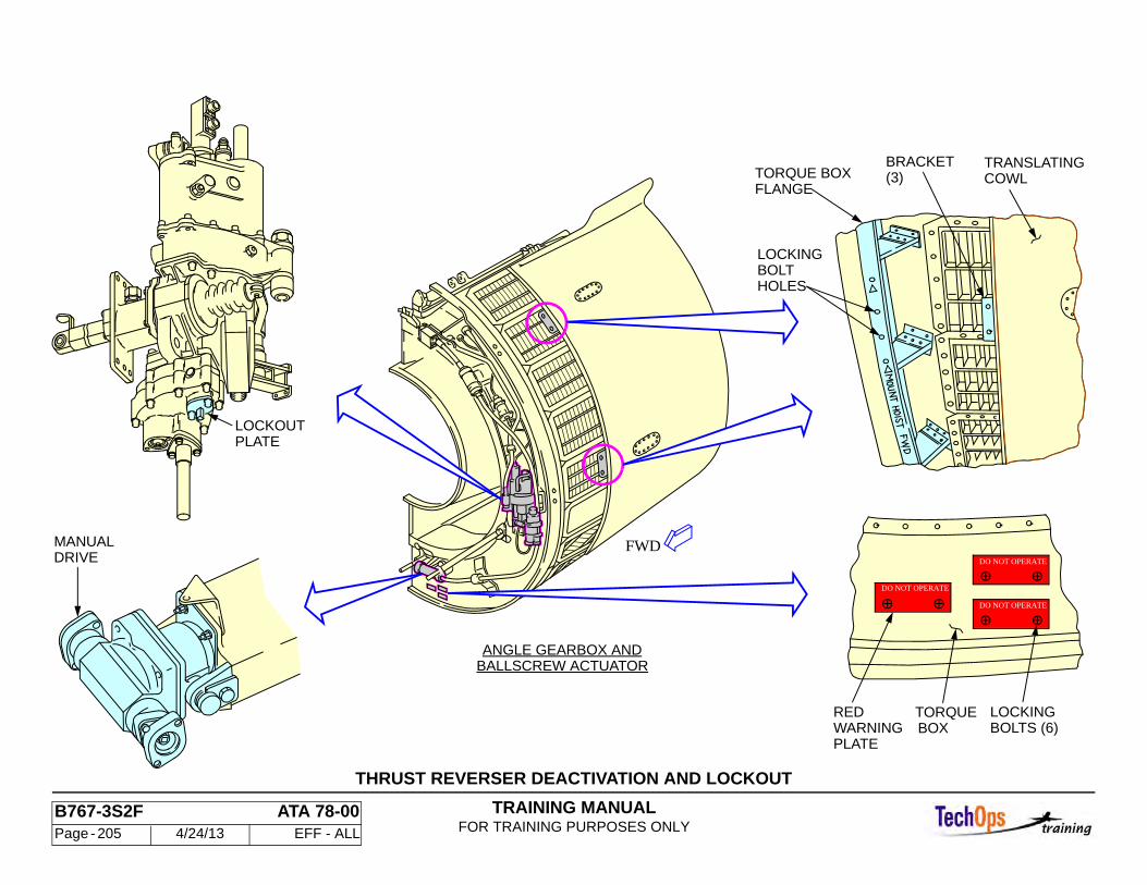
TRAINING MANUALFOR TRAINING PURPOSES ONLY
B767-3S2F ATA 78-00 Page - 205 4/24/13 EFF - ALL
THRUST REVERSER DEACTIVATION AND LOCKOUT
PLATELOCKOUT
FWD
TORQUE BOXFLANGE
BOLTHOLES
LOCKING
TRANSLATINGCOWL(3)
BRACKET
BOXTORQUE
BOLTS (6)LOCKING
DO NOT OPERATE
DO NOT OPERATE
DO NOT OPERATE
REDWARNINGPLATE
MANUALDRIVE
ANGLE GEARBOX ANDBALLSCREW ACTUATOR