B5/B7 NA English Operator Manual - Tennant...
33
B5/B7 9011480 Rev. 03 (12-2014) www.tennantco.com Walk-Behind Battery Burnisher *9011480* North America / International For the latest Parts manuals and other language Operator manuals, visit: www.tennantco.com/manuals English EN Operator Manual TennantTrue Parts
-
Upload
nguyendien -
Category
Documents
-
view
219 -
download
1
Transcript of B5/B7 NA English Operator Manual - Tennant...
B5/B7
9011480Rev. 03 (12-2014)
www.tennantco.com
Walk-Behind Battery Burnisher
*9011480*
North America / InternationalFor the latest Parts manuals and otherlanguage Operator manuals, visit:
www.tennantco.com/manuals
English EN
Operator Manual
TennantTrue Parts

2 Tennant B5/B7 (01- 2014)
INTRODUCTION
This manual is furnished with each new model.It provides necessary operation and maintenanceinstructions.
Read this manual completely andunderstand the machine beforeoperating or servicing it.
A complete illustrated Parts Manual is also furnishedwith each new model. Use the Parts Manual to orderreplacement parts. To ensure prompt delivery, followthe “HOW TO ORDER PARTS” instructions printed inthe Parts Manual.
This machine will provide excellent service. However,the best results will be obtained at minimum costs if:
S The machine is operated with reasonable care.
S The machine is maintained regularly - per themaintenance instructions provided.
S The machine is maintained with manufacturersupplied or equivalent parts.
To view, print or download manuals online visitwww.tennantco.com/manuals
PROTECT THE ENVIRONMENTPlease dispose of packaging materialsand used machine components suchas batteries in an environmentally safeway according to your local wastedisposal regulations.
Always remember to recycle.
Tennant CompanyPO Box 1452Minneapolis, MN 55440Phone: (800) 553- 8033 or (763) 513- 2850
www.tennantco.com
“Set and Forget” is a trademark of Tennant Company.
Trojan and HydroLINK are registered trademarks of Trojan Battery Company.
Specifications and parts are subject to change without notice.
Original Instructions. Copyright E2014 Tennant Company.All rights reserved. Printed in U.S.A.
INTENDED USE
The burnisher machine is intended for commercial use,for example in hotels, schools, hospitals, factories,shops, offices and rental businesses. It is designed toburnish smooth dry hard floor surfaces (VCT, terrazzo,marble, finished hardwood, coated concrete, etc.) in anindoor environment only. Do not use this machine oncarpeted surfaces. Use only recommended burnishingpads intended for machine application. Do not use thismachine other than described in this Operator Manual.
MACHINE DATA
IMPORTANT: To ensure full warranty protection, fill outthe attached MACHINE INSTALLATION / WARRANTYREPORT REPLY CARD and return to Tennant within30 days of purchase.
Please fill out at time of installationfor future reference.
Model No. -
Serial No. -
Installation Date -
Tennant B5/B7 (12- 2014) 3
TABLE OF CONTENTS
INTRODUCTION 2. . . . . . . . . . . . . . . . . . . . . . . . . . . .
INTENDED USE 2. . . . . . . . . . . . . . . . . . . . . . . . . . . .
MACHINE DATA 2. . . . . . . . . . . . . . . . . . . . . . . . . . . .
OPERATIONIMPORTANT SAFETY INSTRUCTIONS 4. . . . . . .
SAFETY LABELS 6. . . . . . . . . . . . . . . . . . . . . . . . . . .
MACHINE COMPONENTS 7. . . . . . . . . . . . . . . . . . .
MACHINE INSTALLATION 8. . . . . . . . . . . . . . . . . . .UNCRATING MACHINE 8. . . . . . . . . . . . . . . . . .INSTALLING BATTERIES 8. . . . . . . . . . . . . . . .
HOW THE MACHINE WORKS 9. . . . . . . . . . . . . . .
MACHINE SETUP 9. . . . . . . . . . . . . . . . . . . . . . . . . .INSTALLING BURNISHING PAD 9. . . . . . . . . .PAD PRESSURE SETTING (Models equipped withmechanical pad pressure adjustment) 10. . . . . .INSTALLING DUST COLLECTION BAGAND HEPA FILTER 11. . . . . . . . . . . . . . . . . . . . .
MACHINE OPERATION 12. . . . . . . . . . . . . . . . . . . . .PRE-OPERATION 12. . . . . . . . . . . . . . . . . . . . . . .OPERATING THE MACHINE 12. . . . . . . . . . . . .EMERGENCY SHUT-OFF BUTTON(Drive Models) 14. . . . . . . . . . . . . . . . . . . . . . . . . .CONTROL CONSOLE ALERT SYMBOLS 14. .WHILE OPERATING THE MACHINE 14. . . . . . .BATTERY DISCHARGE INDICATOR 15. . . . . . .HOUR METER 15. . . . . . . . . . . . . . . . . . . . . . . . . .CIRCUIT BREAKERS / FUSE 15. . . . . . . . . . . . .SERVICE INDICATOR CODES 16. . . . . . . . . . . .
MAINTENANCEMAINTENANCE CHART 18. . . . . . . . . . . . . . . . . . . . .
MACHINE MAINTENANCE 19. . . . . . . . . . . . . . . . . .AFTER DAILY USE 19. . . . . . . . . . . . . . . . . . . . . .AFTER WEEKLY USE 19. . . . . . . . . . . . . . . . . . .AFTER EVERY 50 HOURS OF USE 20. . . . . . .AFTER EVERY 100 HOURS OF USE 20. . . . . .AFTER EVERY 200 HOURS OF USE 20. . . . . .AFTER EVERY 1000 HOURS OF USE 21. . . . .MOTOR MAINTENANCE 21. . . . . . . . . . . . . . . . .
BATTERIES 21. . . . . . . . . . . . . . . . . . . . . . . . . . . . . . . .MAINTENANCE- FREE BATTERIES 21. . . . . . .FLOODED (WET) LEAD- ACID BATTERIES 21CHECKING CONNECTIONS / CLEANING 22. .CHARGING BATTERIES 22. . . . . . . . . . . . . . . . .BATTERY CHARGER SETTINGS 23. . . . . . . . .HYDROLINK BATTERY WATERINGSYSTEM (OPTION) 25. . . . . . . . . . . . . . . . . . . . .
MACHINE JACKING 26. . . . . . . . . . . . . . . . . . . . . . . .
LOADING/UNLOADING MACHINE FORTRANSPORTING 26. . . . . . . . . . . . . . . . . . . . . . . . . .
STORING MACHINE 27. . . . . . . . . . . . . . . . . . . . . . . .
TROUBLESHOOTING 28. . . . . . . . . . . . . . . . . . . . . . .
SPECIFICATIONSB5 GENERAL MACHINE DIMENSIONS/CAPACITIES/PERFORMANCE 29. . . . . . . . . . . . . .
B7 GENERAL MACHINE DIMENSIONS/CAPACITIES/PERFORMANCE 30. . . . . . . . . . . . . . .
B5 MACHINE DIMENSIONS 31. . . . . . . . . . . . . . . . .
B7 MACHINE DIMENSIONS 32. . . . . . . . . . . . . . . . .

OPERATION
4 Tennant B5/B7 (01- 2014)
IMPORTANT SAFETY INSTRUCTIONS - SAVE THESE INSTRUCTIONS
The following warning precautions are used throughoutthis manual as indicated in their description:
WARNING: To warn of hazards or unsafepractices which could result in severe personalinjury or death.
FOR SAFETY: To identify actions which must befollowed for safe operation of equipment.
The following information signals potentiallydangerous conditions to the operator. Know whenthese conditions can exist. Locate all safety devices onthe machine. Report machine damage or faultyoperation immediately.
WARNING: To Reduce the Risk of Fire,Explosion, Electric Shock or Injury:
- Read manual before operating machine.
- Do not use or pick up flammable materials.
- Do not use near flammable liquids, vapors orcombustible dusts.This machine is not equipped with anexplosion proof motor. The electric motor willspark upon start up and during operationwhich could cause a flash fire or explosion ifmachine is used in an area where flammablevapors/liquids or combustible dusts arepresent.
- Batteries emit hydrogen gas. Explosion or firecan result. Keep sparks and open flame awaywhen charging.
- Disconnect battery cables and charger cordbefore cleaning and servicing machine.
- Do not charge batteries with damaged cord. Donot modify plug.
If the charger supply cord is damaged orbroken, it must be replaced by themanufacturer or its service agent or a similarlyqualified person in order to avoid a hazard.
The use of incompatible battery chargers maydamage the battery and potentially cause a firehazard.
- Do not use outdoors or on wet surfaces. Storeindoors. This machine is for dry use only.
- This machine is not suitable for picking uphazardous dust.
- Spinning pad, keep hands away.
FOR SAFETY:
1. Do not operate machine:- Unless trained and authorized.- Unless operator manual is read and
understood.- Unless mentally and physically capable of
following machine instructions.- Under the influence of alcohol or drugs.- While using a cell phone or other types of
electronic devices.- If not in proper operating condition.- In outdoor areas. This machine is for
indoor use only.- With pads or accessories not supplied or
approved by Tennant. The use of otherpads may impair safety.
- In areas with possible falling objects.- In areas that are too dark to safely see the
controls or operate machine.- Without dust bag and filters in place.
2. Before operating machine:- Make sure all safety devices are in place
and operate properly.
3. When operating machine:- Use only as described in this manual.- Report machine damage or faulty operation
immediately.- Wear closed- toe, non- slip work shoes.- Reduce speed when turning.- Keep hands away from spinning pad.- Go slowly on inclines and slippery
surfaces.- Do not burnish on inclines that exceed 9%
grade or transport on inclines that exceed19.5% grade.
- Do not carry passengers on machine.- Use care when reversing machine.- Keep children and unauthorized persons
away from machine.- Do not allow to be used as a toy.
OPERATION
Tennant B5/B7 (01- 2014) 5
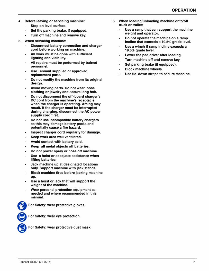
4. Before leaving or servicing machine:- Stop on level surface.- Set the parking brake, if equipped.- Turn off machine and remove key.
5. When servicing machine:- Disconnect battery connection and charger
cord before working on machine.- All work must be done with sufficient
lighting and visibility.- All repairs must be performed by trained
personnel.- Use Tennant supplied or approved
replacement parts.- Do not modify the machine from its original
design.- Avoid moving parts. Do not wear loose
clothing or jewelry and secure long hair.- Do not disconnect the off- board charger’s
DC cord from the machine’s receptaclewhen the charger is operating. Arcing mayresult. If the charger must be interruptedduring charging, disconnect the AC powersupply cord first.
- Do not use incompatible battery chargersas this may damage battery packs andpotentially cause a fire hazard.
- Inspect charger cord regularly for damage.- Keep work area well ventilated.- Avoid contact with battery acid.- Keep all metal objects off batteries.- Do not power spray or hose off machine.- Use a hoist or adequate assistance when
lifting batteries.- Jack machine up at designated locations
only. Support machine with jack stands.- Block machine tires before jacking machine
up.- Use a hoist or jack that will support the
weight of the machine.- Wear personal protection equipment as
needed and where recommended in thismanual.
For Safety: wear protective gloves.
For Safety: wear eye protection.
For Safety: wear protective dust mask.
6. When loading/unloading machine onto/offtruck or trailer:- Use a ramp that can support the machine
weight and operator.- Do not operate the machine on a ramp
incline that exceeds a 19.5% grade level.- Use a winch if ramp incline exceeds a
19.5% grade level.- Lower the pad driver after loading.- Turn machine off and remove key.- Set parking brake (if equipped).- Block machine wheels.- Use tie- down straps to secure machine.

OPERATION
6 Tennant B5/B7 (01- 2014)
SAFETY LABELS
The safety labels appear on the machine in the locations indicated. Replace labels if they are missing or becomedamaged or illegible.
WARNING LABEL - Located on side of control console.
WARNING LABEL -Disconnect batterycables before servicingmachine.Located on control boardcover.
WARNING LABEL -Batteries emithydrogen gas.Explosion or firecan result. Keepsparks and openflame away whencharging.Located on backsideof machine cover.
WARNING LABEL -Spinning Pad. Keep Hands Away.Located on burnishing head.

OPERATION
Tennant B5/B7 (01- 2014) 7
MACHINE COMPONENTS
24
14
3
6
8
12
4
13
109
5
15
7
11
16
17
19
18
1
2
Mechanical Pad Pressure ConsoleAutomated Pad Pressure Console
21
20
23 22
25
26
27 28 29
30
31 32 33 34
1. Cup Holder2. On- board Instruction Guide3. Battery Compartment Hood Latches4. Circuit Breaker Panel, located near batteries.5. Battery Compartment Hood6. Burnishing Pad Motor7. Head Tilt Lock/Release Knob8. Bumper/Head Lift Handle9. Burnishing Head10. Wall Roller11. Dust Control Skirt12. Dust Collection Bag Compartment13. HEPA Filter (Active Dust Collection Model)14. Control Handle15. Start Bail16. Main Power On/Off Key Switch17. USB Program Port18. Emergency Stop Button (Drive Model)
19. Hour Meter20. On- board Battery Charger Cord21. On- board Battery Charger Cord Storage Hooks22. Burnishing Head Lift Pedal23. Anti- static Strap24. Parking Brake (Optional)25. Off- board Battery Charger Receptacle26. Speed Dial (Drive Model)27. Pad Pressure Decrease Button (Automated Model)28. Pad Pressure Indicator (Automatic Model)29. Pad Pressure Increase Button (Automated Model)30. Directional Lever (Drive Model)31. Service Indicator32. Motor Overheat Indicator33. Battery Discharge Indicator34. Check Dust Bag Indicator

OPERATION
8 Tennant B5/B7 (01- 2014)
MACHINE INSTALLATION
UNCRATING MACHINE
1. Carefully check machine for signs of damage.Report damages at once to carrier.
2. Check the contents list. Contact distributor orTennant for missing items.Contents:D Burnishing Pad (pre- installed)D Dust Collection Bag (pre- installed)
Cloth bag (Option)D Battery TrayD Battery Watering System (pre- installed Option)D Off- Board Battery Charger (Option)D Charger Cord/off- board charger model
(Option)D Parts ManualD Use & Care Guide Wall Chart20 in / 510mm Model:D 3 Batteries (pre-installed Option)D 2 Battery CablesD 6 Battery Post Rubber BootsD 1- 2 Foam Battery Spacers24 in/610mm, 27 in/690mm Models:D 6 Batteries (pre-installed Option)D 5 Battery CablesD 12 Battery Post Rubber BootsD 2 Foam Battery Spacers (AGM Batteries)
3. To uncrate the machine, remove straps, wheelblocks and shipping brackets. Using the suppliedramp carefully back the machine off the pallet(Figure 1). Make sure the burnishing head is in theraised position.
ATTENTION: Do not remove machine from palletwithout using ramp, machine damage may occur.
FIG. 1
INSTALLING BATTERIES
Contact distributor or Tennant for batteryrecommendations if machine is not supplied withbatteries.
IMPORTANT: For machine’s supplied with batteriesand battery charger, the battery discharge indicator isfactory programmed for battery type supplied. Formachine’s supplied without batteries, the machine’sbattery discharge indicator (BDI) is pre- programmed towork with wet/lead acid batteries as the default. Ifinstalling a different battery type (i.e. sealed, AGMbatteries, etc.) the battery discharge indicator will needto be reprogrammed to prevent battery damage. SeeBATTERIES for further details.
BATTERY SPECIFICATIONS:B5 Model -3- 12 volt, deep cycle, 185 AH wet lead acid batteries(Push Model).
3- 12 volt, deep cycle, 225 AH wet lead acid batteries(Drive Model).
3- 12 volt, deep cycle, 234 AH AGM sealed batteries(Optional, Push and Drive Models)
B7 Model -6- 6 volt, deep cycle, 240 AH wet lead acid batteries(24 in/610mm Model).
6- 6 volt, deep cycle, 330 AH wet lead acid batteries(27 in/690mm Models).
6- 6 volt, deep cycle, 360 AH wet lead acid batteries(Optional, 24 in/610mm, 27 in/690mm Models).
6 - 6 volt, deep cycle, 312 AH AGM sealed batteries(Optional, 24 in/610mm, 27 in/690mm Models)
WARNING: Fire Or Explosion Hazard.Batteries emit hydrogen gas. Explosion or fire canresult. Keep sparks and open flame away whencharging.
FOR SAFETY: When servicing machine, wearappropriate personal protection equipment asneeded. Avoid contact with battery acid.
1. Park the machine on a level surface, turn machineoff and remove the key.
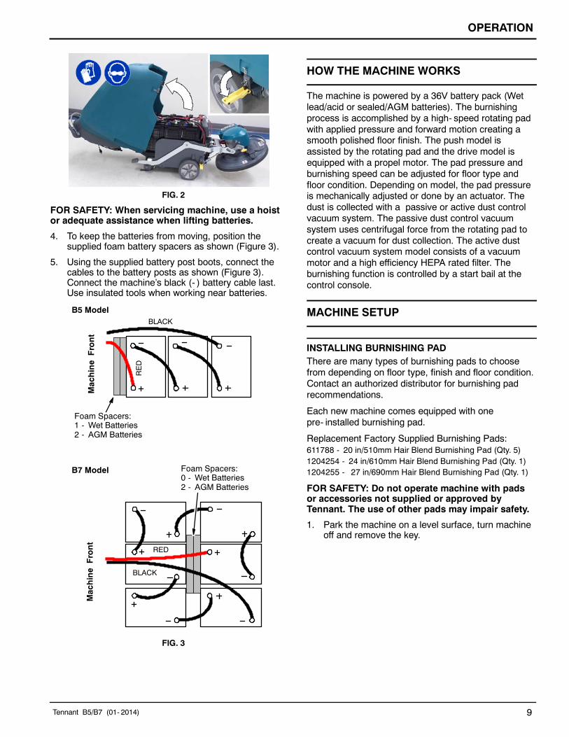
2. Unlatch the battery compartment hood latches andlift the hood backwards (Figure 2).
3. With adequate assistance carefully install thebatteries into the battery compartment. Arrange thebatteries as shown (Figure 3).
OPERATION
Tennant B5/B7 (01- 2014) 9
FIG. 2
FOR SAFETY: When servicing machine, use a hoistor adequate assistance when lifting batteries.
4. To keep the batteries from moving, position thesupplied foam battery spacers as shown (Figure 3).
5. Using the supplied battery post boots, connect thecables to the battery posts as shown (Figure 3).Connect the machine’s black (- ) battery cable last.Use insulated tools when working near batteries.
RED
BLACK
MachineFront
Foam Spacers:0 - Wet Batteries2 - AGM Batteries
MachineFront
B7 Model
B5 Model
Foam Spacers:1 - Wet Batteries2 - AGM Batteries
RED
BLACK
FIG. 3
HOW THE MACHINE WORKS
The machine is powered by a 36V battery pack (Wetlead/acid or sealed/AGM batteries). The burnishingprocess is accomplished by a high- speed rotating padwith applied pressure and forward motion creating asmooth polished floor finish. The push model isassisted by the rotating pad and the drive model isequipped with a propel motor. The pad pressure andburnishing speed can be adjusted for floor type andfloor condition. Depending on model, the pad pressureis mechanically adjusted or done by an actuator. Thedust is collected with a passive or active dust controlvacuum system. The passive dust control vacuumsystem uses centrifugal force from the rotating pad tocreate a vacuum for dust collection. The active dustcontrol vacuum system model consists of a vacuummotor and a high efficiency HEPA rated filter. Theburnishing function is controlled by a start bail at thecontrol console.
MACHINE SETUP
INSTALLING BURNISHING PADThere are many types of burnishing pads to choosefrom depending on floor type, finish and floor condition.Contact an authorized distributor for burnishing padrecommendations.
Each new machine comes equipped with onepre- installed burnishing pad.
Replacement Factory Supplied Burnishing Pads:611788 - 20 in/510mm Hair Blend Burnishing Pad (Qty. 5)1204254 - 24 in/610mm Hair Blend Burnishing Pad (Qty. 1)1204255 - 27 in/690mm Hair Blend Burnishing Pad (Qty. 1)
FOR SAFETY: Do not operate machine with padsor accessories not supplied or approved byTennant. The use of other pads may impair safety.
1. Park the machine on a level surface, turn machineoff and remove the key.

OPERATION
10 Tennant B5/B7 (01- 2014)
2. Step down and to the left on the burnishing head liftpedal to raise head off floor (Figure 4). Pull thehead lift handle upward until head locks into thepad change position.
FIG. 4
3. Install the burnishing pad on pad driver (Figure 5).Make sure pad is centered on pad driver. Securepad with center- lock. Do not operate machinewithout pad center- lock installed.
FIG. 5
4. Pull the head tilt lock knob to release the head fromthe pad change position (Figure 6).
FIG. 6
PAD PRESSURE SETTING (Models equipped withmechanical pad pressure adjustment)
For models equipped with mechanical pad pressureadjustment, the pad pressure is factory set at theoptimal setting. Many variables come in to play toachieving optimal burnishing performance; floor type,floor finish, floor condition and pad type.
To confirm that the factory setting best meets yourburnishing application, it’s recommended to perform thefollowing procedure. Once the pad pressure is properlyset for your burnishing application, this will provideconsistent performance for your routine burnishingschedule. This is referred to as the “Set and Forget”method.
1. To activate the pad pressure mode, locate thehidden button (small indent) on the left side of thecontrol panel (Figure 7).
2. Press and hold the hidden button and turn the keyon. Hold the button until a single green light appearsat the battery discharge indicator (Figure 7). Whenthe button is released, the green light will turn off andthe service indicator symbol will turn on.
The machine is now ready to verify the current padpressure.
FIG. 7
3. Pull the start bail and begin burnishing for aminimum of 10 seconds (Figure 8). The LED’s willripple then a single light will appear confirming thecurrent pad pressure setting. See the followingchart for down pressure settings.
FIG. 8

OPERATION
Tennant B5/B7 (01- 2014) 11
LED Code =On Down Pressure Setting
S S S S Flashing - Too Low
S S S S Low
S S S S Medium Low
S S S S Medium
S S S S Medium High
S S S S High
S S S S Flashing - Too High
The medium down pressure setting is recommended.Determine the burnishing performance at this settingand adjust as necessary.
To adjust pressure setting proceed to the next step.
4. Raise the burnishing head and remove key. Locatethe pad pressure adjustment cotter pin (Figure 9).
FIG. 9
5. To increase down pressure, move the cotter pin tothe next hole towards the motor. To decrease thedown pressure move the cotter pin in oppositedirection (Figure 10).
FIG. 10
6. Repeat steps 1- 3 and adjust the pin until desireddown pressure is achieved.
INSTALLING DUST COLLECTION BAG AND HEPAFILTER
Each new machine is equipped with one pre- installedpaper bag. Models equipped with the optional ActiveDust Control system includes a pre- installed HEPAfilter.
Replacement bags/filters:p/n 1210869 - 1 package/10 paper bagsp/n 1208744 - Cloth bag (optional).p/n 1203162 - HEPA filter
NOTE: The optional cloth bag is not intended formodels equipped with the Active Dust Control system.
FOR SAFETY: Do not operate machine withoutdust bag and filters in place.
1. Park the machine on a level surface, turn machineoff and remove the key.
2. Remove the the cover from the dust collection bagcompartment. Press the two cover tabs to removecover (Figure 11).
FIG. 11
3. Install dust bag and HEPA filter as shown. Replacecover (Figure 12). The HEPA filter is included withthe Active Dust Collection model.
FIG. 12

OPERATION
12 Tennant B5/B7 (07- 2014)
4. The check dust bag indicator will periodically lightup on the control console alerting operator to checkbag for fullness. Replace the bag when it becomeshalf full (Figure 13). Restart the key to reset thecheck bag indicator.
FIG. 13
5. The HEPA filter requires to be replaced every 200hours of use (Figure 14).
FIG. 14
MACHINE OPERATION
FOR SAFETY: Do not operate machine unlessoperator manual is read and understood.
PRE-OPERATION
- Sweep floor and remove any obstructions.
- Scrub floor from any soil buildup.
- Check that the floor surface is dry.Do not use machine with spray buffing solution.
- Check battery discharge level indicator.
- Select proper burnishing pad.
- Check condition of burnishing pad.
- Check dust collection bag for fullness.
- Check vacuum hose connection at bag compartment.
- Check machine for proper operation.
OPERATING THE MACHINE
1. Lower the burnishing head to the floor by releasingthe burnishing head lift pedal as shown (Figure 15).
FIG. 15
2. Release the parking brake lever if equipped(Figure 16)
3. Turn the key to the on ( I ) position (Figure 16).
FIG. 16
4. For drive models, push the directional lever to theforward position (Figure 17). To reverse machine pullthe directional lever backwards.
FORWARD
REVERSE
FIG. 17

OPERATION
Tennant B5/B7 (01- 2014) 13
5. To begin burnishing, pull the start bail (Figure 18).The burnishing head will draw to the floor by suction.
FIG. 18
6. For push models, slowly push the machine forward.The rotating brush will help assist the machineforward.
For drive models, adjust the burnishing speed byturning the speed dial to the desired speed(Figure 19).
FIG. 19
7. For models equipped with automated downpressure, adjust the pad pressure to the desiredsetting by pressing the increase or decrease padpressure buttons (Figure 20). For optimalperformance set the pad pressure indicator to thecenter LED setting.
FIG. 20
For models equipped with mechanical padpressure, the pad pressure setting is factory set foroptimal performance. To confirm the pad pressureis properly set for your burnishing application, seePAD PRESSURE SETTING in the MACHINESETUP section.
8. To stop burnishing, release the start bail (Figure21). The drive model has an electromagnetic brakesystem that will automatically stop the machinewhen the bail is released.
FIG. 21
9. To transport the machine from one location toanother, raise the burnishing head to the transportposition (Figure 22).
FIG. 22
OPERATION
14 Tennant B5/B7 (01- 2014)
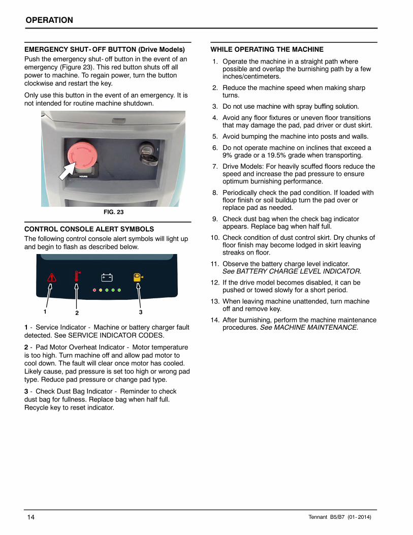
EMERGENCY SHUT-OFF BUTTON (Drive Models)Push the emergency shut- off button in the event of anemergency (Figure 23). This red button shuts off allpower to machine. To regain power, turn the buttonclockwise and restart the key.
Only use this button in the event of an emergency. It isnot intended for routine machine shutdown.
FIG. 23
CONTROL CONSOLE ALERT SYMBOLSThe following control console alert symbols will light upand begin to flash as described below.
1 2 3
1 - Service Indicator - Machine or battery charger faultdetected. See SERVICE INDICATOR CODES.
2 - Pad Motor Overheat Indicator - Motor temperatureis too high. Turn machine off and allow pad motor tocool down. The fault will clear once motor has cooled.Likely cause, pad pressure is set too high or wrong padtype. Reduce pad pressure or change pad type.
3 - Check Dust Bag Indicator - Reminder to checkdust bag for fullness. Replace bag when half full.Recycle key to reset indicator.
WHILE OPERATING THE MACHINE
1. Operate the machine in a straight path wherepossible and overlap the burnishing path by a fewinches/centimeters.
2. Reduce the machine speed when making sharpturns.
3. Do not use machine with spray buffing solution.
4. Avoid any floor fixtures or uneven floor transitionsthat may damage the pad, pad driver or dust skirt.
5. Avoid bumping the machine into posts and walls.
6. Do not operate machine on inclines that exceed a9% grade or a 19.5% grade when transporting.
7. Drive Models: For heavily scuffed floors reduce thespeed and increase the pad pressure to ensureoptimum burnishing performance.
8. Periodically check the pad condition. If loaded withfloor finish or soil buildup turn the pad over orreplace pad as needed.
9. Check dust bag when the check bag indicatorappears. Replace bag when half full.
10. Check condition of dust control skirt. Dry chunks offloor finish may become lodged in skirt leavingstreaks on floor.
11. Observe the battery charge level indicator.See BATTERY CHARGE LEVEL INDICATOR.
12. If the drive model becomes disabled, it can bepushed or towed slowly for a short period.
13. When leaving machine unattended, turn machineoff and remove key.
14. After burnishing, perform the machine maintenanceprocedures. See MACHINE MAINTENANCE.
OPERATION
Tennant B5/B7 (01- 2014) 15
BATTERY DISCHARGE INDICATOR
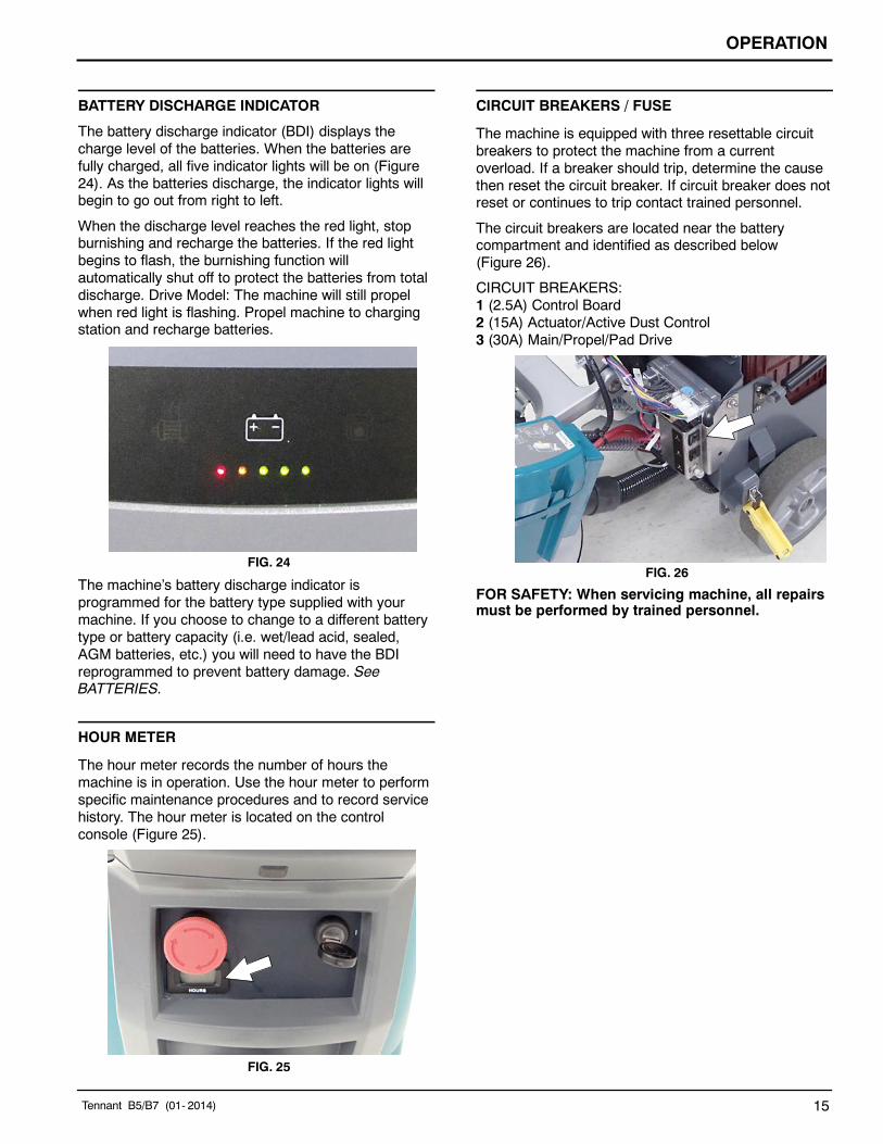
The battery discharge indicator (BDI) displays thecharge level of the batteries. When the batteries arefully charged, all five indicator lights will be on (Figure24). As the batteries discharge, the indicator lights willbegin to go out from right to left.
When the discharge level reaches the red light, stopburnishing and recharge the batteries. If the red lightbegins to flash, the burnishing function willautomatically shut off to protect the batteries from totaldischarge. Drive Model: The machine will still propelwhen red light is flashing. Propel machine to chargingstation and recharge batteries.
FIG. 24
The machine’s battery discharge indicator isprogrammed for the battery type supplied with yourmachine. If you choose to change to a different batterytype or battery capacity (i.e. wet/lead acid, sealed,AGM batteries, etc.) you will need to have the BDIreprogrammed to prevent battery damage. SeeBATTERIES.
HOUR METER
The hour meter records the number of hours themachine is in operation. Use the hour meter to performspecific maintenance procedures and to record servicehistory. The hour meter is located on the controlconsole (Figure 25).
FIG. 25
CIRCUIT BREAKERS / FUSE
The machine is equipped with three resettable circuitbreakers to protect the machine from a currentoverload. If a breaker should trip, determine the causethen reset the circuit breaker. If circuit breaker does notreset or continues to trip contact trained personnel.
The circuit breakers are located near the batterycompartment and identified as described below(Figure 26).
CIRCUIT BREAKERS:1 (2.5A) Control Board2 (15A) Actuator/Active Dust Control3 (30A) Main/Propel/Pad Drive
FIG. 26
FOR SAFETY: When servicing machine, all repairsmust be performed by trained personnel.
OPERATION
16 Tennant B5/B7 (12- 2014)
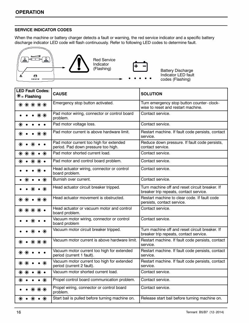
SERVICE INDICATOR CODES
When the machine or battery charger detects a fault or warning, the red service indicator and a specific batterydischarge indicator LED code will flash continuously. Refer to following LED codes to determine fault.
Red ServiceIndicator(Flashing) Battery Discharge
Indicator LED faultcodes (Flashing)
LED Fault Codes:= Flashing
CAUSE SOLUTION
Emergency stop button activated. Turn emergency stop button counter- clock-wise to reset and restart machine.
S S S Pad motor wiring, connector or control boardproblem.
Contact service.
S S S S Pad motor voltage loss. Contact service.
S S Pad motor current is above hardware limit. Restart machine. If fault code persists, contactservice.
S S S Pad motor current too high for extendedperiod. Pad down pressure too high.
Reduce down pressure. If fault code persists,contact service.
S Pad motor shorted current load. Contact service.
S S Pad motor and control board problem. Contact service.
S S S S Head actuator wiring, connector or controlboard problem.
Contact service.
S S S Burnish over current. Contact service.
S S S Head actuator circuit breaker tripped. Turn machine off and reset circuit breaker. Ifbreaker trip repeats, contact service.
S Head actuator movement is obstructed. Restart machine to clear code. If fault codepersists, contact service.
S Head actuator or vacuum motor and controlboard problem.
Contact service.
S S S S Vacuum motor wiring, connector or controlboard problem
Contact service.
S S S Vacuum motor circuit breaker tripped. Turn machine off and reset circuit breaker. Ifbreaker trip repeats, contact service.
S Vacuum motor current is above hardware limit. Restart machine. If fault code persists, contactservice.
S S S Vacuum motor current too high for extendedperiod (current 1 fault).
Restart machine. If fault code persists, contactservice.
S S Vacuum motor current too high for extendedperiod (current 2 fault).
Restart machine. If fault code persists, contactservice.
S S Vacuum motor shorted current load. Contact service.
S S S Propel control board communication problem. Contact service.
S S Propel wiring, connector or control boardproblem.
Contact service.
S S Start bail is pulled before turning machine on. Release start bail before turning machine on.

OPERATION
Tennant B5/B7 (12- 2014) 17
SERVICE INDICATOR CODES - Continued
LED Fault Code:= Flashing
CAUSE SOLUTION
S S S Propel motor short. Contact service.
S S S Propel circuit breaker tripped. Turn machine off and reset circuit breaker. Ifbreaker trip repeats, contact service.
S S Software load failure. Contact service.
On-Board Battery Charger Service Indicator codes:
LED Fault Code:= Flashing
CAUSE SOLUTION
S S Charger error condition. Contact service.
S S S Charger is not connected to battery pack. Check cable connections.
S S S SCharger overheated. Let charger cool. Move to well ventilated area.
Charge batteries in areas with temperatures80F/27C or less. If fault persists, contactservice.
S S Charger not communicating with machine. Restart charger. If fault code persists, contactservice.
S S Charger timer exceeded maximum chargingtime. Interrupts charging cycle.
Replace Batteries.
MAINTENANCE
18 Tennant B5/B7 (12- 2014)
MAINTENANCE CHART
3
4
11
8
2
5
1
6
9
10
7
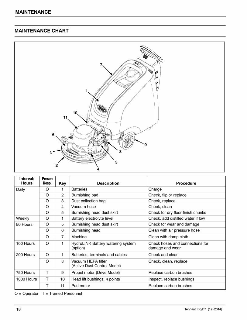
Interval/Hours
PersonResp. Key Description Procedure
Daily O 1 Batteries ChargeO 2 Burnishing pad Check, flip or replaceO 3 Dust collection bag Check, replaceO 4 Vacuum hose Check, cleanO 5 Burnishing head dust skirt Check for dry floor finish chunks
Weekly O 1 Battery electrolyte level Check, add distilled water if low
50 Hours O 5 Burnishing head dust skirt Check for wear and damage
O 6 Burnishing head Clean with air pressure hose
O 7 Machine Clean with damp cloth
100 Hours O 1 HydroLINK Battery watering system(option)
Check hoses and connections fordamage and wear
200 Hours O 1 Batteries, terminals and cables Check and clean
O 8 Vacuum HEPA filter(Active Dust Control Model)
Check, clean, replace
750 Hours T 9 Propel motor (Drive Model) Replace carbon brushes
1000 Hours T 10 Head lift bushings, 4 points Inspect, replace bushings
T 11 Pad motor Replace carbon brushes
O = Operator T = Trained Personnel

MAINTENANCE
Tennant B5/B7 (12- 2014) 19
MACHINE MAINTENANCE
To keep the machine in good working condition, simplyperform the following maintenance procedures.
FOR SAFETY: Before leaving or servicing machine,stop on level surface, turn off machine, remove keyand set parking brake if equipped.
FOR SAFETY: When servicing machine wearpersonal protection equipment as needed. Allrepairs must be performed by trained personnel
AFTER DAILY USE
1. Flip the burnishing pad over or change to a newpad (Figure 27).
FIG. 27
2. Check the dust collection bag for fullness. Replacebag when half full (Figure 28).
FIG. 28
3. Check vacuum hose for clogging. Clean hose asnecessary (Figure 29).
FIG. 29
4. Charge batteries (Figure 30). See BATTERIES forcharging instructions.
ON- BOARD CHARGER OFF- BOARD CHARGERFIG. 30
AFTER WEEKLY USE
Check the electrolyte level in all batteries (Figure 31).See BATTERIES for further details.
FIG. 31

MAINTENANCE
20 Tennant B5/B7 (12- 2014)
AFTER EVERY 50 HOURS OF USE
1. Check the dust skirt for wear or damage(Figure 32). Replace if worn or damaged.
FIG. 32
2. Clean the burnishing head and pad motor of anydust buildup using an air pressure hose (Figure33). Maximum air pressure 100 psi / 690 kPa.
FOR SAFETY: When servicing machine, wearappropriate personal protection equipment asneeded
FIG. 33
3. Clean the outside surface of the machine with anall purpose cleaner and damp cloth (Figure 34).
FIG. 34
AFTER EVERY 100 HOURS OF USEIf machine is equipped with the optional HydroLINKbattery watering system, check the watering hoses andconnections for damage and wear (Figure 35). Replacesystem if damaged.
FOR SAFETY: When servicing batteries, wearpersonal protection equipment as needed. Avoidcontact with battery acid.
FIG. 35
AFTER EVERY 200 HOURS OF USE1. Clean batteries and check for loose battery cable
connections (See BATTERY MAINTENANCE).2. Replace the HEPA filter if model is equipped with
the active dust control collection option (Figure 36).
FIG. 36

MAINTENANCE
Tennant B5/B7 (12- 2014) 21
AFTER EVERY 1000 HOURS OF USE
Inspect the four bushings at the head lift bracketassembly for wear (Figure 37). If you experience headbounce or vibration, have the bushings replaced.
FIG. 37
MOTOR MAINTENANCE
Replace motor carbon brushes as indicated. Contacttrained personnel for carbon brush replacement.
Carbon Brush Replacement Hours
Propel Motor (Drive Model) 750
Pad Motor 1000
BATTERIES
FOR SAFETY: Before servicing machine, stop onlevel surface, turn off machine, remove key and setparking brake if equipped.
The lifetime of the batteries depends on their propermaintenance. To get the most life from the batteries;
S Do not charge the batteries more than once a dayand only after running the machine for a minimum of15 minutes.
S Do not leave the batteries partially discharged forlong period of time.
S Only charge the batteries in a well-ventilated area toprevent gas build up. Charge batteries in areas withambient temperatures 27_C (80_F) or less.
S Allow the charger to complete charging the batteriesbefore re-using the machine.
S Maintain the proper electrolyte levels of flooded (wet)batteries by checking levels weekly.
Your machine is equipped with either flooded (wet)lead- acid or maintenance- free batteries supplied byTennant.
FOR SAFETY: When servicing machine, keep allmetal objects off batteries. Avoid contact withbattery acid.
MAINTENANCE-FREE BATTERIES
Maintenance- free (Sealed AGM) batteries do notrequire watering. Cleaning and other routinemaintenance is still required.
FLOODED (WET) LEAD-ACID BATTERIESThe flooded (wet) lead- acid batteries require routinewatering as described below. Check the batteryelectrolyte level weekly.
NOTE: Do Not check the electrolyte level if themachine is equipped with the battery watering system.Proceed to the BATTERY WATERING SYSTEM(OPTION).
The level should be slightly above the battery plates asshown before charging. Add distilled water if low. DONOT OVERFILL. The electrolyte will expand and mayoverflow when charging. After charging, distilled watercan be added up to about 3 mm (0.12 in) below thesight tubes.
Before Charging After Charging
FIG. 38
NOTE: Make sure the battery caps are in place whilecharging. There may be a sulfur smell after chargingbatteries. This is normal.

MAINTENANCE
22 Tennant B5/B7 (12- 2014)
CHECKING CONNECTIONS / CLEANING
After every 200 hours of use, check for loose batteryconnections and clean the surface of the batteries,including terminals and cable clamps to prevent batterycorrosion. Use a scrub brush with a strong mixture ofbaking soda and water (Figure 39). Do not removebattery caps when cleaning batteries.
FIG. 39
CHARGING BATTERIES
The charging instructions in this manual are intendedfor the battery charger supplied with your machine. Theuse of other battery chargers that are not supplied andapproved by Tennant are prohibited. If your machine isequipped with an off- board battery charger refer to thecharger’s owners manual for operating instructions.Contact distributor or Tennant for battery chargerrecommendations if machine is not equipped withcharger.
FOR SAFETY: The use of incompatible batterychargers may damage battery packs andpotentially cause a fire hazard.If the on- board battery charger detects a problem whilein use, the machine will display a service code. SeeSERVICE INDICATOR CODES. For off- board batterycharger error codes refer the to manual supplied withcharger.
Battery Charger Specifications:
S CHARGER TYPE:- For wet (Lead acid) Batteries- For Sealed (AGM) Batteries
S OUTPUT VOLTAGE - 36 VOLTS
S OUTPUT CURRENT - 25 AMPS
S AUTOMATIC SHUTOFF CIRCUIT
S FOR DEEP CYCLE BATTERY CHARGING
IMPORTANT NOTICE: The battery charger is set tocharge the battery type supplied with your machine. Ifyou choose to change to a different battery type orcapacity (i.e. flooded (wet) lead- acid,maintenance- free, sealed, AGM batteries, etc.), thebattery charger and the machine’s battery dischargeindicator (BDI) must be reprogrammed to preventbattery damage. See BATTERY CHARGERSETTINGS.
1. Transport the machine to a well- ventilated area.
WARNING: Fire Or Explosion Hazard.Batteries emit hydrogen gas. Explosion or fire canresult. Keep sparks and open flame away whencharging.
2. Park the machine on a flat, dry surface, turn offmachine and remove key.
FOR SAFETY: When servicing batteries, stop onlevel surface, turn off machine, remove key and setparking brake if equipped.
3. If the machine is equipped with flooded (wet) lead-acid batteries check the battery electrolyte levelweekly before charging. See FLOODED (WET)LEAD-ACID BATTERIES.
4. For models equipped with on- board chargers,remove the charger’s power cord from the storagehooks and plug power cord into a properlygrounded wall outlet (Figure 40).
FIG. 40
For models equipped with off- board chargers, firstconnect the charger’s DC cord into the machine’sbattery charge receptacle then plug the AC powersupply cord into a properly grounded wall outlet(Figure 41). Refer to the off- board batterycharger’s owner manual for operating instructions.
FOR SAFETY: Do not disconnect the off- boardcharger’s DC cord from the machine’s receptaclewhen the charger is operating. Arcing may result. Ifthe charger must be interrupted during charging,disconnect the AC power supply cord first.
MAINTENANCE
Tennant B5/B7 (12- 2014) 23
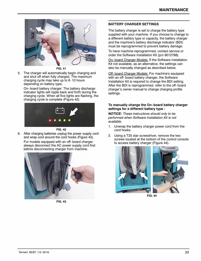
FIG. 41
5. The charger will automatically begin charging andand shut off when fully charged. The maximumcharging cycle may take up to 6- 10 hoursdepending on battery type.On- board battery charger: The battery dischargeindicator lights will ripple back and forth during thecharging cycle. When all five lights are flashing, thecharging cycle is complete (Figure 42).
FIG. 426. After charging batteries unplug the power supply cord
and wrap cord around the cord hooks (Figure 43).For models equipped with an off- board charger,always disconnect the AC power supply cord firstbefore disconnecting charger from machine.
FIG. 43
BATTERY CHARGER SETTINGS
The battery charger is set to charge the battery typesupplied with your machine. If you choose to change toa different battery type or capacity, the battery chargerand the machine’s battery discharge indicator (BDI)must be reprogrammed to prevent battery damage.
To have machine reprogrammed, contact service ororder the Software Installation Kit (p/n 9012788).
On- board Charger Models: If the Software InstallationKit not available, as an alternative, the settings canalso be manually changed as described below.
Off- board Charger Models: For machine’s equippedwith an off- board battery changer, the SoftwareInstallation Kit is required to change the BDI setting.After the BDI is reprogrammed, refer to the off- boardcharger’s owner manual to change charging profilesettings.
To manually change the On- board battery chargersettings for a different battery type :NOTICE: These instructions should only to beperformed when Software Installation Kit is notavailable.
1. Unwrap the battery charger power cord from thecord hooks.
2. Using a T25 star screwdriver, remove the twoscrews located at the bottom of the control consoleto access battery charger (Figure 44).
FIG. 44

MAINTENANCE
24 Tennant B5/B7 (12- 2014)
3. Carefully peel back the charger display label toaccess the dial settings (Figure 45).
FIG. 45
4. Using a small standard screwdriver, turn the dial tothe appropriate battery type according to thefollowing chart (Figure 46).
FIG. 46
NOTE: The only time the dial should be changed fromthe “0” position is when changing to a different batterytype and Software Installation Kit is not available. Thepreferred method is to use the Software Installation Kitand keeping the dial set at the “0” position at all times.
When using the Software Installation Kit, the dial MUSTbe set to the “0”position to properly program otherwisebattery damage may result.
DialPosition Battery Description Settings
0 Software Program Setting (all battery types)
1 Wet, Trojan 180- 250 AH
2 Wet, Trojan 260- 360 AH
3 Wet, Enersys 200- 350 AH
4 AGM, Discover 200- 300 AH
5 AGM, Fullriver 200- 350 AH
6 Gel, Sonnenschein 150- 250 AH
5. Re- apply the display label.
6. Replace the control console.
7. To set the BDI to the new battery type, plug theon- board battery charger cord into an electricaloutlet. The machine’s software will automaticallyreprogram the BDI to the new battery type.

MAINTENANCE
Tennant B5/B7 (12- 2014) 25
HYDROLINK BATTERY WATERING SYSTEM(OPTION)
The following instructions are for models equipped withthe HydroLINK battery watering system option.
The optional HydroLINK battery watering systemprovides a safe and easy way to maintain the properelectrolyte levels in your batteries.
This battery watering system is also offered as anaftermarket kit (p/n 9010301). It is designed exclusivelyfor Trojan flooded (wet) lead- acid batteries.
FOR SAFETY: When servicing machine, wearpersonal protection equipment as needed. Avoidcontact with battery acid.
Before using the battery watering system check hosesand connections for damage or wear.
1. Fully charge batteries prior to using the batterywatering system. Do not add water to batteriesbefore charging, the electrolyte level will expandand may overflow when charging.
2. After charging batteries, check the batteryelectrolyte level indicators located on the batterycovers (Figure 47). If the level indicator is whiteadd water as described in the followinginstructions. If the level indicators are black theelectrolyte is at the correct level, no water isrequired.
FIG. 47
3. Locate the battery fill hose coupler inside thebattery compartment. Remove the dust cap andconnect the hand pump hose (Figure 48).
FIG. 48
4. Submerge the other end of the hand pump hoseinto a bottle of distilled water (Figure 49).
DistilledWater
FIG. 49
5. Squeeze the bulb on the hand pump hose until firm(Figure 50). The level indicators will turn blackwhen full.
FIG. 50
6. After adding water, replace the dust cap on thebattery fill hose and store the hand pump hoseinside the machine’s battery compartment for futureuse.

MAINTENANCE
26 Tennant B5/B7 (01- 2014)
MACHINE JACKING
FOR SAFETY: Before leaving or servicingmachine, stop on level surface, turn off machineand remove key.
Use the designated jacking locations for jacking up themachine (Figure 51). Use a jack capable of supportingthe weight of the machine. Position the machine on aflat, level surface and block the tires before jacking.
FOR SAFETY: When servicing machine, jackmachine up at designated locations only. Use jackor hoist that will support machine weight. Blockmachine up with jack stands.
FIG. 51
LOADING/UNLOADING MACHINE FORTRANSPORTING
When transporting the machine by use of trailer ortruck, carefully follow the loading and tie- downprocedure:
1. Raise the burnishing head to the transport positionto prevent potential head damage when ramploading machine on truck or trailer (Figure 52).
FIG. 52
2. Use a ramp that can support the machine weightand operator and carefully load machine. Do notoperate the machine on a ramp incline thatexceeds a 19.5% grade level (Figure 53). A winchmust be used when ramp incline exceeds a 19.5%grade level.
FOR SAFETY: When loading/unloading machineonto/off truck or trailer, use a ramp that cansupport the machine weight and operator.
Do not operate the machine on a ramp incline thatexceeds a 19.5% grade level. Use tie- down strapsto secure machine to truck or trailer.
19.5% maximum ramp grade
FIG. 53
3. Once loaded, position the front of the machine upagainst the front of the trailer or truck. Lower theburnishing head to the floor and turn the key off(Figure 54).
4. Place a block behind each wheel (Figure 54).
5. Using tie- down straps, secure the front and rear ofthe machine using the four tie- down bracketslocated on the machine frame (Figure 54). It maybe necessary to install tie-down brackets to thefloor of your trailer or truck. Do not use theburnishing head lift pedal as a tie down.
FIG. 54
6. When unloading machine, carefully back themachine down the ramp. Do not unload machinegoing in the forward direction.

MAINTENANCE
Tennant B5/B7 (01- 2014) 27
STORING MACHINE
The following steps should be taken when storing themachine for extended periods of time.
1. Charge the batteries before storing machine toprolong the life of the batteries. Recharge batteriesevery 3 months.
2. Raise the burnishing head off the floor.
3. Park the machine in a cool, dry area.
4. Turn machine off and remove key.
NOTE: To prevent potential machine damage storemachine in a rodent and insect free environment.
WARNING: To Reduce the Risk of Fire,Explosion, Electric Shock or Injury do not exposethe machine to rain, store indoors.
5. For storage areas with limited space, raise thehead as shown (Figure 55).
FIG. 55

MAINTENANCE
28 Tennant B5/B7 (07- 2014)
TROUBLESHOOTINGPROBLEM CAUSE SOLUTION
Service indicator symbolis flashing.
Machine or on- board battery chargerfault has been detected
See SERVICE INDICATOR CODES in manual
No power Emergency stop button activated Turn button to reset
Batteries discharged Recharge batteries
Loose or disconnected battery cable Secure battery cable connections
Circuit breaker tripped Reset circuit breaker
Faulty key switch Contact Service Center
Machine does not propel(Drive Model)
Propel fault has been detected. See SERVICE INDICATOR CODES in manual
Circuit breaker tripped Reset circuit breaker
Faulty propel motor or wiring Contact Service Center
Worn carbon brushes in motor Contact Service Center
Pad motor does notoperate
Low voltage interrupter activated Recharge batteries
Pad motor fault has been detected. See SERVICE INDICATOR CODES in manual
Faulty pad motor or wiring Contact Service Center
Worn carbon brushes in motor Contact Service Center
Vacuum motor does notoperate(Active Dust CollectionModel)
Vacuum motor fault has been detected See SERVICE INDICATOR CODES in manual
Faulty vacuum motor or wiring Contact Service Center
Circuit breaker tripped on vacuum Reset circuit breaker button
Push model is not brushassisted
Burnishing head angle not properlyadjusted
Contact Service Center
Battery charger will notoperate
Batteries over discharged Replace batteries
Battery charger fault detected See SERVICE INDICATOR CODES in manual
Faulty charger Replace charger
Poor burnishingperformance
Worn pad Flip or replace pad
Pad pressure incorrect Adjust pad pressure
See Setting Pad Pressure
Short run time Low battery charge Charge batteries
Batteries need maintenance See BATTERY MAINTENANCE.
Defective battery or end of battery life Replace batteries
Battery discharge indicator (BDI)programmed incorrectly
See CHARGING BATTERIES
Pad pressure too high Decrease pad pressure
See Setting Pad Pressure
Faulty charger Replace battery charger
Machine vibration Pad not properly centered Remove and reinstall pad
Improper pad for application Change to proper pad
Pad unevenly worn Replace pad
Soiled pad Replace pad
Worn head lift bracket bushings Inspect, replace bushings
SPECIFICATIONS
Tennant B5/B7 (07- 2014) 29
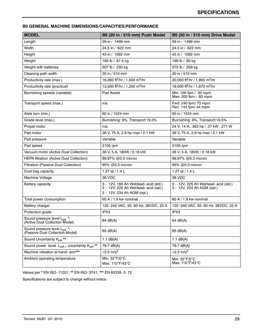
B5 GENERAL MACHINE DIMENSIONS/CAPACITIES/PERFORMANCE
MODEL B5 (20 in / 510 mm) Push Model B5 (20 in / 510 mm) Drive Model
Length 59 in / 1499 mm 59 in / 1499 mm
Width 24.5 in / 622 mm 24.5 in / 622 mm
Height 43 in / 1092 mm 43 in / 1092 mm
Weight 193 lb / 87.5 kg 198 lb / 90 kg
Weight with batteries 507 lb / 230 kg 572 lb / 259 kg
Cleaning path width 20 in / 510 mm 20 in / 510 mm
Productivity rate (max.) 16,260 ft2/hr / 1,500 m2/hr 20,000 ft2/hr / 1,900 m2/hr
Productivity rate (practical) 13,500 ft2/hr / 1,200 m2/hr 18,000 ft2/hr / 1,670 m2/hr
Burnishing speeds (variable) Pad Assist Min: 100 fpm / 30 mpmMax: 200 fpm / 60 mpm
Transport speed (max.) n/a Fwd: 240 fpm/ 73 mpmRev: 144 fpm/ 44 mpm
Aisle turn (min.) 60 in / 1524 mm 60 in / 1524 mm
Grade level (max.) Burnishing: 9%, Transport:19.5% Burnishing: 9%, Transport:19.5%
Propel motor n/a 24 V, 14 A, .363 hp / .27 kW , 271 W
Pad motor 36 V, 75 A, 2.8 hp max / 2.1 kW 36 V, 75 A, 2.8 hp max / 2.1 kW
Pad pressure Variable Variable
Pad speed 2100 rpm 2100 rpm
Vacuum motor (Active Dust Collection) 36 V, 5 A, 180W / 0.18 kW 36 V, 5 A, 180W / 0.18 kW
HEPA filtration (Active Dust Collection) 99.97% @0.3 micron 99.97% @0.3 micron
Filtration (Passive Dust Collection) 95% @0.3 micron 95% @0.3 micron
Dust bag capacity 1.27 qt / 1.4 L 1.27 qt / 1.4 L
Machine Voltage 36 VDC 36 VDC
Battery capacity 3 - 12V, 185 Ah Wet/lead- acid (std.)3 - 12V, 225 Ah Wet/lead- acid (opt.)3 - 12V, 234 Ah AGM (opt.)
3 - 12V, 225 Ah Wet/lead- acid (std.)3 - 12V, 234 Ah AGM (opt.)
Total power consumption 60 A / 1.9 kw nominal 60 A / 1.9 kw nominal
Battery charger 120- 240 VAC, 50- 60 Hz, 36VDC, 25 A 120- 240 VAC, 50- 60 Hz, 36VDC, 25 A
Protection grade IPX3 IPX3
Sound pressure level LpA *(Active Dust Collection Model) 64 dB(A) 64 dB(A)
Sound pressure level LpA *(Passive Dust Collection Model) 65 dB(A) 65 dB(A)
Sound Uncertainty KpA ** 1.1 dB(A) 1.1 dB(A)
Sound power level LwA + uncertainty KwA ** 79.7 dB(A) 79.7 dB(A)
Machine vibration at hand- arm*** <2.5 m/s2 <2.5 m/s2
Ambient operating temperature Min: 32F/0CMax: 110F/43C
Min: 32F/0CMax: 110F/43C
Values per * EN ISO- 11201, ** EN ISO- 3741, *** EN 60335- 2- 72
Specifications are subject to change without notice.

SPECIFICATIONS
30 Tennant B5/B7 (12- 2014)
B7 GENERAL MACHINE DIMENSIONS/CAPACITIES/PERFORMANCE
MODEL B7 (24 in / 610 mm) Drive Model B7 (27 in / 690 mm) Drive Model
Length 61.5 in / 1562 mm 63 in / 1602 mm
Width 30 in / 762 mm 31.5 in / 800 mm
Height 43 in / 1092 mm 43 in / 1092 mm
Weight 246 lb / 111.5 kg 254 lb / 115 kg
Weight with batteries 616 lb / 279 kg 797 lb / 361 kg
Cleaning path width 24 in / 610 mm 27 in / 690 mm
Productivity rate (max.) 24,000 ft2/hr / 2,200 m2/hr 27,000 ft2/hr / 2,500 m2/hr
Productivity rate (practical) 22,000 ft2/hr / 2,000 m2/hr 25,000 ft2/hr / 2,300 m2/hr
Burnishing speeds (variable) Min: 100 fpm / 30 mpmMax: 200 fpm / 60 mpm
Min: 100 fpm / 30 mpmMax: 200 fpm / 60 mpm
Transport speed (max.) Fwd: 240 fpm/ 73 mpmRev: 144 fpm/ 44 mpm
Fwd: 240 fpm/ 73 mpmRev: 144 fpm/ 44 mpm
Aisle turn (min.) 62.5 in / 1588 mm 64 in / 1626 mm
Grade level (max.) Burnishing: 9%, Transport:19.5% Burnishing: 9%, Transport:19.5%
Propel motor 24 V, 14 A, .363 hp / .27 kW , 271 W 24 V, 14 A, .363 hp / .27 kW , 271 W
Pad motor 37 V, 90 A, 3.6 hp max / 2.6 kW 37 V, 90 A, 3.6 hp max / 2.6 kW
Pad pressure Variable Variable
Pad speed 1875 rpm 1875 rpm
Vacuum motor (Active Dust Collection) 36 V, 5 A, 180W / 0.18 kW 36 V, 5 A, 180W / 0.18 kW
HEPA filtration (Active Dust Collection) 99.97% @0.3 micron 99.97% @0.3 micron
Filtration (Passive Dust Collection) 95% @0.3 micron 95% @0.3 micron
Dust bag capacity 1.27 qt / 1.4 L 1.27 qt / 1.4 L
Machine Voltage 36 VDC 36 VDC
Battery capacity 6 - 6V, 240 Ah Wet/lead- acid (std.)6 - 6V, 312 Ah AGM (opt.)6 - 6V, 360 Ah Wet/lead- acid (opt.)
6 - 6V, 330 Ah Wet/lead- acid (std.)6 - 6V, 312 Ah AGM (opt.)6 - 6V, 360 Ah Wet/lead- acid (opt.)
Total power consumption 75 A / 2.7 kw nominal 75 A / 2.7 kw nominal
Battery charger 120- 240 VAC, 50- 60 Hz, 36VDC, 25 A 120- 240 VAC, 50- 60 Hz, 36VDC, 25 A
Protection grade IPX3 IPX3
Sound pressure level LpA *(Active Dust Collection Model) 63 dB(A) 63 dB(A)
Sound pressure level LpA *(Passive Dust Collection Model) 65 dB(A) 65 dB(A)
Sound Uncertainty KpA ** 1.1 dB(A) 1.1 dB(A)
Sound power level LwA + uncertainty KwA ** 79.7 dB(A) 79.7 dB(A)
Machine vibration at hand- arm*** <2.5 m/s2 <2.5 m/s2
Ambient operating temperature Min: 32F/0CMax: 110F/43C
Min: 32F/0CMax: 110F/43C
Values per * EN ISO- 11201, ** EN ISO- 3741, *** EN 60335- 2- 72
Specifications are subject to change without notice.

SPECIFICATIONS
Tennant B5/B7 (01- 2014) 31
B5 MACHINE DIMENSIONS
24.5 in / 622 mm
59 in / 1,499 mm
43 in1,092 mm

SPECIFICATIONS
32 Tennant B5/B7 (01- 2014)
B7 MACHINE DIMENSIONS
30 in / 762 mm(24 in / 610 mm Model)
43 in1,092 mm
31.5 in / 800 mm(27 in / 690 mm Model)
63 in / 1,602 mm(27 in / 690 mm Model)
61.5 in / 1,562 mm(24 in / 610 mm Model)