B503SL SERIES Solar Photovoltaic Pump...
32
B503SL SERIES Solar Photovoltaic Pump Controller INSTRUCTION MANUAL V1.0.1 GUANGZHOU BEDFORD ELECTRIC EQUIPMENT.CO.,LTD.
Transcript of B503SL SERIES Solar Photovoltaic Pump...
B503SL SERIES Solar Photovoltaic Pump Controller
INSTRUCTION MANUAL
V1.0.1
GUANGZHOU BEDFORD ELECTRIC EQUIPMENT.CO.,LTD.


CONTENTS
SAFETY PRECAUTIONS.............................................................................................................................. 2 1 SPECIFICATION ...................................................................................................................................... 3
1.1 Output 3AC 380V.............................................................................................................................. 3 1.2 Output 3AC 220V.............................................................................................................................. 3 1.3 Description of Name Plate ................................................................................................................. 4 1.4 Selection Guide.................................................................................................................................. 4 1.5 Parts Description................................................................................................................................ 5 1.6 External Dimension ........................................................................................................................... 6
2 INSTALLATION ....................................................................................................................................... 6 2.1 Installation Space............................................................................................................................... 6
3 WIRING .................................................................................................................................................... 7 3.1 Schematic........................................................................................................................................... 7 3.2 Solar cell array power supply ............................................................................................................ 8 3.3 Solar cell array and AC power supply ............................................................................................... 9 3.4 Specifications of breaker, cable. ...................................................................................................... 10 3.5 The wiring of water-level automatic control.....................................................................................11
4 OPERATION ........................................................................................................................................... 16 4.1 Keypad Description ......................................................................................................................... 16
4.1.1 Keypad schematic diagram ................................................................................................... 16 4.1.2 key function description........................................................................................................ 16 4.1.3 Indicator light description ..................................................................................................... 17
4.2 Operation Process ............................................................................................................................ 17 4.2.1 Parameter setting................................................................................................................... 17 4.2.2 Fault reset.............................................................................................................................. 18
4.3 Running State................................................................................................................................... 18 4.3.1 Power-on initialization.......................................................................................................... 18 4.3.2 stand -by................................................................................................................................ 18 4.3.4 Running state ........................................................................................................................ 19
5 PARAMETER FUNCTION .................................................................................................................... 20 6 INITIAL DEBUGGING .......................................................................................................................... 23 7 TROUBLE SHOOTING.......................................................................................................................... 24
7.1 fault and trouble shooting ................................................................................................................ 24 7.2 Common Faults and Solutions ......................................................................................................... 25
8 MAINTENANCE .................................................................................................................................... 26 8.1 Daily Maintenance........................................................................................................................... 26 8.2 Periodic Maintenance....................................................................................................................... 27 8.3 Replacement of wearing parts.......................................................................................................... 28 8.4 Warranty........................................................................................................................................... 28

1
Thanks for choosing our product, we will supply you with considerate service as well as ever.
This product is suitable for solar photovoltaic pump system, aimed at environmental and
economy market, to replace battery with retain water and without any battery components.
Photovoltaic Pump Controller receives the DC which produced by Solar Modules and then
transform into AC to drive all kinds of pump directly. It is reaction rapidly, little temperature and humidity influence, balance the system’s supply and demands, do well in energy-saving, and so on.
●Through adopting advanced MPPT technology ,this product can make full use of the
efficiency of the solar cell array.
● It can automatically adjust the motor speed and the water flow along with the intensity of
sunlight.
● Automatic sleep when on high-water level and automatic restart when on low-water level to
realize automatic control through water level.
● Can prevent pump from anhydrous idling;
● It also can enter automatically to sleep mode when the intensity of sunlight is weak (e.g. the
sunset.), as well as can exit the sleep mode when the intensity of sunlight is becoming strong
(e.g. the sun rise.).
● Protect itself in trouble and improve the reliability of whole system.
2
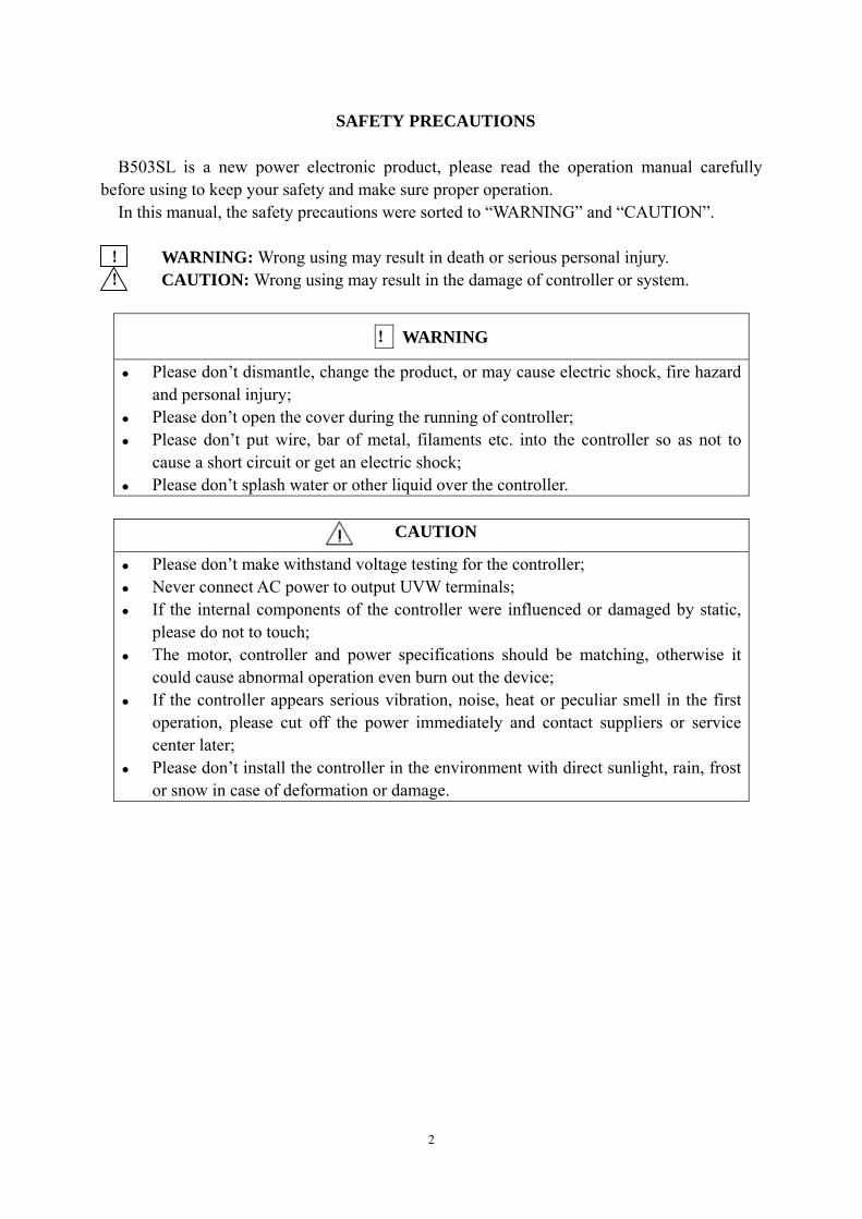
SAFETY PRECAUTIONS
B503SL is a new power electronic product, please read the operation manual carefully before using to keep your safety and make sure proper operation.
In this manual, the safety precautions were sorted to “WARNING” and “CAUTION”.
! WARNING: Wrong using may result in death or serious personal injury. ! CAUTION: Wrong using may result in the damage of controller or system.
! WARNING
Please don’t dismantle, change the product, or may cause electric shock, fire hazard and personal injury;
Please don’t open the cover during the running of controller; Please don’t put wire, bar of metal, filaments etc. into the controller so as not to
cause a short circuit or get an electric shock; Please don’t splash water or other liquid over the controller.
CAUTION
Please don’t make withstand voltage testing for the controller; Never connect AC power to output UVW terminals; If the internal components of the controller were influenced or damaged by static,
please do not to touch; The motor, controller and power specifications should be matching, otherwise it
could cause abnormal operation even burn out the device; If the controller appears serious vibration, noise, heat or peculiar smell in the first
operation, please cut off the power immediately and contact suppliers or service center later;
Please don’t install the controller in the environment with direct sunlight, rain, frost or snow in case of deformation or damage.

3
1 SPECIFICATION
1.1 Output 3AC 380V
Maximum input DC voltage 800VDC
Recommended DC input voltage range 420~720VDC
Recommended input working voltage 540VDC
The number of Input port 1
Rated output voltage 3AC 380V
Output frequency range 0~600Hz
Cooling method Air cooling
altitude
This controller should be installed with
altitude of lower than 1000m.
It will be degraded when the altitude higher
than 1000m. For details, rated output current
should be degraded 1% for every 100m
Standard CE
1.2 Output 3AC 220V
Maximum input DC voltage 410VDC
Recommended DC input voltage range 220-370VDC
Recommended input working voltage 305VDC
The number of Input port 1
Rated output voltage 3AC 220V
Output frequency range 0~600Hz
Cooling method Air cooling
Altitude
This controller should be installed with
altitude of lower than 1000m.
It will be degraded when the altitude higher
than 1000m. For details, rated output current
should be degraded 1% for every 100m
Standard CE

4
1.3 Description of Name Plate
B503SL-4010
Figure1.1 Nameplate of controller
1.4 Selection Guide
1)Output 3AC 380V
Model No. Rated
Output Powe(KW)
Rated Input Current(A)
Rated Output
Current(A)
Motor Power (KW)
Size
Output 3AC 380V B503SL-4001 0.75 3.4 2.5 0.75 B B503SL-4002 1.5 5.0 3.7 1.5 B B503SL-4003 2.2 5.8 5 2.2 B B503SL-4005 4.0 10 9 4.0 C B503SL-4007 5.5 15 13 5.5 C B503SL-4010 7.5 20 17 7.5 D B503SL-4015 11 26 25 11 D B503SL-4020 15 35 32 15 D B503SL-4025 18.5 38 37 18.5 E B503SL-4030 22 46 45 22 E B503SL-4040 30 62 60 30 E
Please contact company for other specification. 2)Output 3AC 220V
Model No. Rated
Output Power(KW)
Rated Input Current(A)
Rated Output
Current(A)
Motor Power (KW)
Size
Output 3AC 220V B503SL-2001 0.75 5.0 4.5 0.75 A B503SL-2002 1.5 7.7 7 1.5 B B503SL-2003 2.2 11.0 10 2.2 B B503SL-2005 3.7 17.0 16 3.7 C B503SL-2007 5.5 21.0 20 5.5 C B503SL-2010 7.5 31.0 30 7.5 D
Current Vector Control
Output Voltage Class 4—380V 2—220V
Power Symbol 010—10HP/7.5kw 015—15HP/11kw

5
Model No. Rated
Output Power(KW)
Rated Input Current(A)
Rated Output
Current(A)
Motor Power (KW)
Size
B503SL-2015 11.0 43.0 42 11.0 E B503SL-2020 15 56.0 55 15.0 E B503SL-2025 18.5 71.0 70 18.5 E
Please contact company for other specification
1.5 Parts Description
Figure 1.2 Parts of controllers(15KW and below)
Figure 1.3 Parts of controllers (18.5KW and above)
6
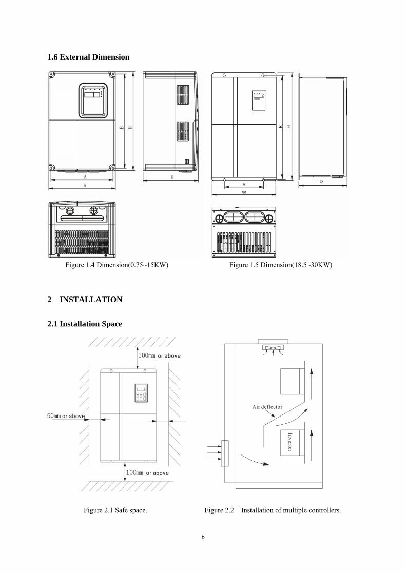
1.6 External Dimension
Figure 1.4 Dimension(0.75~15KW) Figure 1.5 Dimension(18.5~30KW)
2 INSTALLATION
2.1 Installation Space
Figure 2.1 Safe space. Figure 2.2 Installation of multiple controllers.
7
Notice: Add the air deflector when apply the up-down installation.
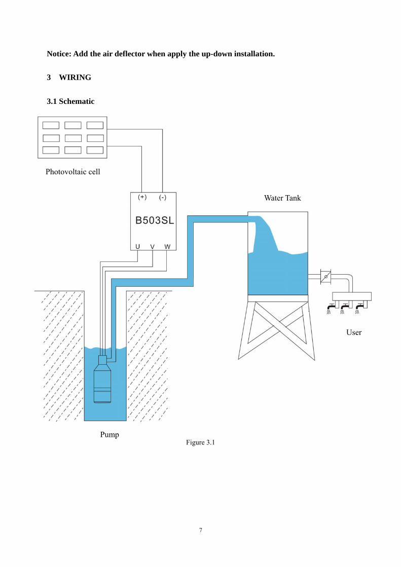
3 WIRING
3.1 Schematic
Figure 3.1
Photovoltaic cell
Pool
Solar Photovoltaic Pump Controller
Pump
Photovoltaic cell
Water Tank
User

8
3.2 Solar cell array power supply
Figure 3.2
Motor-pump
Photovoltaic cell
9
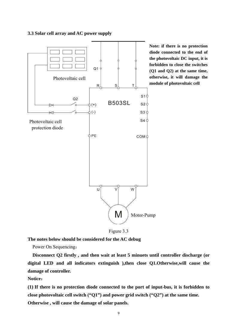
3.3 Solar cell array and AC power supply
Figure 3.3
The notes below should be considered for the AC debug Power On Sequencing:
Disconnect Q2 firstly , and then wait at least 5 minuets until controller discharge (or
digital LED and all indicators extinguish ),then close Q1.Otherwise,will cause the
damage of controller. Notice:
(1) If there is no protection diode connected to the port of input-bus, it is forbidden to
close photovoltaic cell switch (“Q1”) and power grid switch (“Q2”) at the same time.
Otherwise , will cause the damage of solar panels.
Note: if there is no protection diode connected to the end of the photovoltaic DC input, it is forbidden to close the switches (Q1 and Q2) at the same time, otherwise, it will damage the module of photovoltaic cell
Photovoltaic cell protection diode
Photovoltaic cell
Motor-Pump

10
(2) When need to transform the power supply mode from power frequency to
photovoltaic cell; you only need to turn off “Q1”firstly and then close “Q2”. Main circuit terminal functions are summarized according to the terminal to the terminal
symbols in the following table. Wire the terminal correctly for the desired purposes. Terminal Symbol Function Description
R、S、T Terminals of 3 phase AC input (+)、(-) Terminals of DC input
U、V、W Terminals of 3 phase AC output
/PE Terminals of ground
S1,S2 Input terminals of Water-level detection signal for the wells
S3,S4 Input terminals of Water-level detection signal for the reservoir
COM Input common terminal of water-level detection signal
3.4 Specifications of breaker, cable.
Model No. Circuit Breaker (A) Input/ Output Cable ( 2mm )
B503SL-2001 16 2.5 B503SL-2002 20 4 B503SL-2003 32 6 B503SL-2005 40 6 B503SL-2007 63 6 B503SL-2010 100 10 B503SL-2015 125 25 B503SL-2020 160 25 B503SL-2025 160 25 B503SL-4001 10 2.5 B503SL-4002 16 2.5 B503SL-4003 16 2.5 B503SL-4005 25 4 B503SL-4007 25 4 B503SL-4010 40 6 B503SL-4015 63 6 B503SL-4020 63 6 B503SL-4025 100 10 B503SL-4030 100 16 B503SL-4040 125 25
Please contact company for other specification

11
3.5 The wiring of water-level automatic control
3.5.1 The wiring to prevent pump from anhydrous idling
3.5.1.1 The wiring for floater water-level switch connected by cable
The common port ,which using floater water-level switch connected by cable ,is fed to the
terminal “COM” of B503 SL controller . And then ,select NO (Normally Open )and connect to
“S1” (S1and S2 connected together ). If the NC was connected to “S1”, the parameter
“F0.12 ”should be set as follow: S1=1,S2=1.
Figure 3.4 the low water-level Figure 3.5 the high water-level
Remarks: when the actual water-level in the wells is higher than the horizontal line of
high water-level ,“S1” and “S2”will be connected to the “COM” as well as controller
automatically will start the pump.On the contrary, if the actual water-level is lower than the
horizontal line of low water-level ,“S1” and “S2”will be disconnected from “COM”as well as
controller automatically stop the pump to prevent anhydrous idling.
3.5.1.2 the wiring for floater water-level switch connected by rod
The floater water-level switch connected by rod is the normally open contact to output
and its common wire is connected to the terminal “COM”of B503SL controller.At the same
time ,the low level-water wire is connected to the terminal “S1” of B503SL controller and the
high water-level wire is connected the terminal “S2” .If the NC was selected,the parameter
F0.12 should be set as follow:S1=1,S2=1.
Low water-level
High water-level

12
Figure 3.6 low water-level Figure 3.7 high water-level Remarks: when the actual water-level in the wells is higher than the horizontal line of high
water-level ,“S1”and “S2” will be connected to the “COM”as well as controller automatically
start the pump .On the contrary, if the actual water-level is lower than the horizontal line of
low water-level ,“S1”and“S2”will be disconnected from“COM”as well as controller
automatically stop the pump to prevent anhydrous idling.
3.5.1.3 The wiring for water-level sensors
There are three signal leads as given (left image)for
detecting water-level. The shortest signal line is ,which is ①
corresponding to the horizontal line of high water-level ,is
connected to the terminal “S2”of controller. The signal line ②
that is corresponding to the horizontal line of low water- level
need to be connected to the terminal “S1” . The longest line is
,which is corresponding to the common port is connected to ③
the terminal “COM”of controller.
Remarks :
when the actual water-level in the wells is higher than
the horizontal line of high water-level ,“S1”and“S2”will be connected to the “COM”as well as
controller automatically start the pump .On the contrary, if the actual water-level is lower than
the horizontal line of low water-level ,“S1”and“S2”will be disconnected from “COM”as well
as controller automatically stop the pump to prevent anhydrous idling.
Notice : if only use one detection signal of water-level in the wells , “S1”and “S2”
must be connected together by conductor.
low water-level
high water-level
High
water-level
Low
water-level
13
3.5.2 The wiring of reservoir
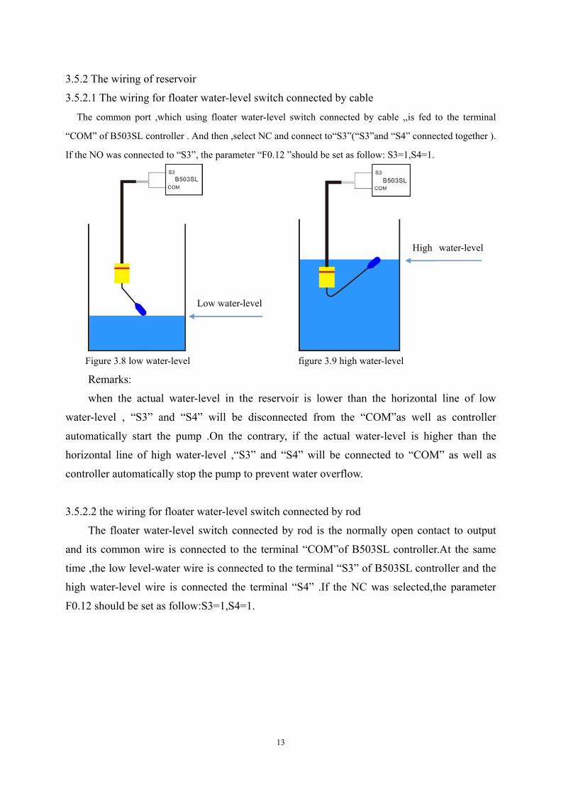
3.5.2.1 The wiring for floater water-level switch connected by cable
The common port ,which using floater water-level switch connected by cable ,,is fed to the terminal
“COM” of B503SL controller . And then ,select NC and connect to“S3”(“S3”and “S4” connected together ).
If the NO was connected to “S3”, the parameter “F0.12 ”should be set as follow: S3=1,S4=1.
Figure 3.8 low water-level figure 3.9 high water-level
Remarks:
when the actual water-level in the reservoir is lower than the horizontal line of low
water-level , “S3” and “S4” will be disconnected from the “COM”as well as controller
automatically start the pump .On the contrary, if the actual water-level is higher than the
horizontal line of high water-level ,“S3” and “S4” will be connected to “COM” as well as
controller automatically stop the pump to prevent water overflow.
3.5.2.2 the wiring for floater water-level switch connected by rod
The floater water-level switch connected by rod is the normally open contact to output
and its common wire is connected to the terminal “COM”of B503SL controller.At the same
time ,the low level-water wire is connected to the terminal “S3” of B503SL controller and the
high water-level wire is connected the terminal “S4” .If the NC was selected,the parameter
F0.12 should be set as follow:S3=1,S4=1.
Low water-level
High water-level
14
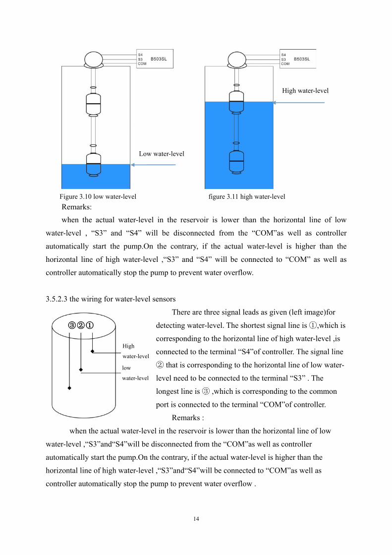
Figure 3.10 low water-level figure 3.11 high water-level Remarks: when the actual water-level in the reservoir is lower than the horizontal line of low
water-level , “S3” and “S4” will be disconnected from the “COM”as well as controller
automatically start the pump.On the contrary, if the actual water-level is higher than the
horizontal line of high water-level ,“S3” and “S4” will be connected to “COM” as well as
controller automatically stop the pump to prevent water overflow.
3.5.2.3 the wiring for water-level sensors
There are three signal leads as given (left image)for
detecting water-level. The shortest signal line is ,which is ①
corresponding to the horizontal line of high water-level ,is
connected to the terminal “S4”of controller. The signal line
that is corresponding to the horizontal line of low water② -
level need to be connected to the terminal “S3” . The
longest line is ,which is corresponding to the common ③
port is connected to the terminal “COM”of controller.
Remarks :
when the actual water-level in the reservoir is lower than the horizontal line of low
water-level ,“S3”and“S4”will be disconnected from the “COM”as well as controller
automatically start the pump.On the contrary, if the actual water-level is higher than the
horizontal line of high water-level ,“S3”and“S4”will be connected to “COM”as well as
controller automatically stop the pump to prevent water overflow .
Low water-level
High water-level
High
water-level
low
water-level

15
低水位
3.5.3 the wiring for floater water-level switch mounted on a side
The floater water-level switch mounted on a side is the normally open contact to output
and its common wire is connected to the terminal “COM”of B503SL controller.At the same
time ,the low level-water wire is connected to the terminal “S3” of B503SL controller and the
high water-level wire is connected the terminal “S4”.If the NC was selected,the parameter
F0.12 should be set as follow:S3=1,S4=1.
Figure 3.12 low water-level figure 3.13 high water-level
Remarks:
when the actual water-level in the reservoir is lower than the horizontal line of low water-level , “S3”
and “S4” will be disconnected from the “COM”as well as controller automatically start the pump .On the
contrary, if the actual water-level is higher than the horizontal line of high water-level ,“S3” and “S4” will
be connected to “COM” as well as controller automatically stop the pump o prevent water overflow.
Notice:
1 . If only use one detection signal of water-level in the reservoir , “S3”and “S4” must be
connected together by conductor.
2 . It is required to modify the wiring of floater switch’s NC or NO according to the parameter
setting (F0.12)
Low water-level
High water-level
Detector switch Of high water-level
Detector Switch Of low Water-level
Detector switch Of high water-level
Detector Switch Of low
B503SL
B503SL B503SL
B503SL
16
4 OPERATION
4.1 Keypad Description
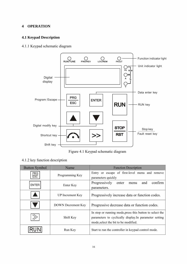
4.1.1 Keypad schematic diagram
Figure 4.1 Keypad schematic diagram
4.1.2 key function description
Button Symbol Name Function Description
Programming Key
Entry or escape of first-level menu and remove parameters quickly
Enter Key
Progressively enter menu and confirm parameters.
UP Increment Key Progressively increase data or function codes.
DOWN Decrement Key Progressive decrease data or function codes.
Shift Key
In stop or running mode,press this button to select the parameters to cyclically display.In parameter setting mode,select the bit to be modified.
Run Key Start to run the controller in keypad control mode.

17
Button Symbol Name Function Description
STOP/RESET Key
In running status, can be used to stop the controller. When fault alarm, can be used to reset the controller in any control mode
Jog Key Jog
+
Combination Key Pressing the RUN and STOP/RST at the same time can achieve controller coast to stop.
4.1.3 Indicator light description
4.1.3.1 Function Indicator Light Description Indicator Light Name Indicator Light Description
RUN/TUNE Extinguished: stop status Light on: operation status
LOC/REM Extinguished: keypad control Flickering:terminal control.
FAULT Extinguished: normal operation status Light on:overload pre-warning status
4.1.3.2 Unit Indicator Light Description Symbol Description
Hz Frequency unit A Current unit V Voltage unit
RPM Rotation speed unit % Percentage
4.1.3.3 Digital Display
Have 5 digit LED , which can display all kinds of monitoring data and alarm codes such as reference frequency, output frequency and so on.
4.2 Operation Process
4.2.1 Parameter setting
Three levels of menu are:
1、Function code group (first-level);
2、Function code (second-level);
18
3、Function code value (third-level).
Remarks: Press both the PRG/ESC and the ENTER can return to the second-class menu
from the third-class menu. The difference is: pressing ENTER will save the set parameters
into the control panel, and then return to the second-class menu with shifting to the next
function code automatically; while pressing PRG/ESC will directly return to the second-class
menu without saving the parameters, and keep staying at the current function code
4.2.2 Fault reset
If the controller has fault, it will prompt the related fault information. User can use
STOP/RST to reset the fault. After fault reset, the controller is at stand-by state. If user does
not reset the controller when it is at fault state, the controller will be at operation protection
state, and can not run.
4.3 Running State
4.3.1 Power-on initialization
Firstly the system initializes during the controller power-on, and LED displays “SL503”,
and seven indicator lights are all on. After the initialization is completed, the controller is on
stand-by status.
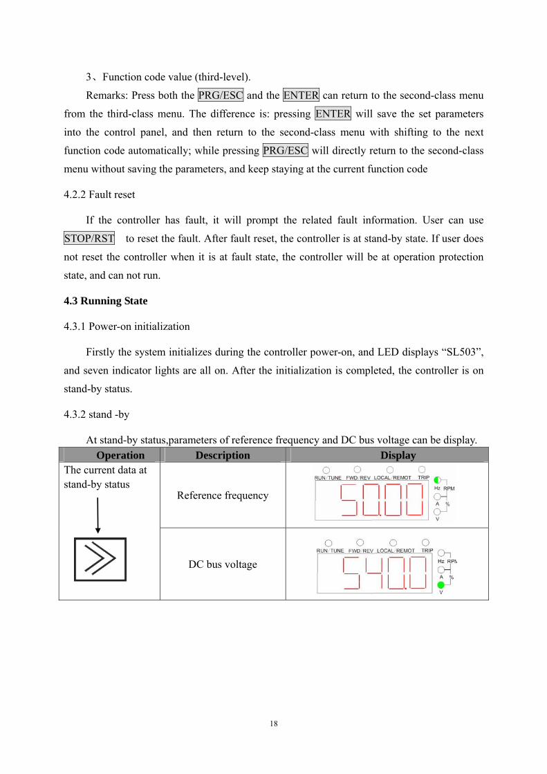
4.3.2 stand -by
At stand-by status,parameters of reference frequency and DC bus voltage can be display. Operation Description Display
Reference frequency
The current data at stand-by status
DC bus voltage
19
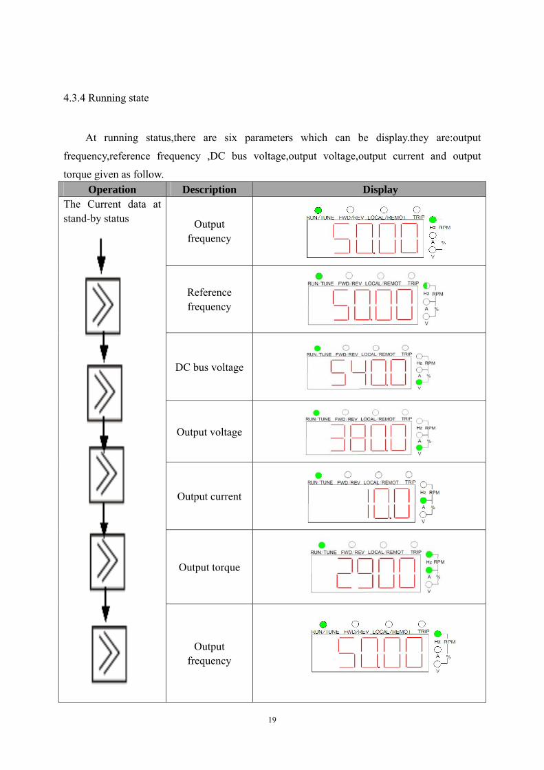
4.3.4 Running state
At running status,there are six parameters which can be display.they are:output
frequency,reference frequency ,DC bus voltage,output voltage,output current and output
torque given as follow. Operation Description Display
Output frequency
Reference frequency
DC bus voltage
Output voltage
Output current
Output torque
The Current data at stand-by status
Output frequency

20
5 PARAMETER FUNCTION
Function code
Name Description Factory setting
F0.00 Run command
source
0:water-level automatic control through keypad start/ stop 1:water-level automatic control 2:manual control through keypad
0
F0.01 Upper
frequency limit
Output frequency range:0~600.00Hz 50.00Hz
F0.02 Lower
frequency
If output frequency is lower than F0.02 and DC bus voltage is low than F0.04,the controller stop .please refer to description of F0.04
30.0Hz
F0.03 Restart delay
time
Restart delay time after power on .please refer to description of F0.13 when using.
10s
100~900V(OUTPUT 220V series) 200V
F0.04
Output threshold
voltage after start
Only DC bus voltage is greater than the value of F0.04 to give rise output.
100~900V(OUTPUT 380Vseries) 400V
100~900V(OUTPUT 220Vseries) 305V F0.05
Maximum power point ‘s
voltage
PV array voltage correspond to maximum power point
100~900V(OUTPUT 380Vseries) 540V
100~900V(OUTPUT 220Vseries) 400V F0.06
Open circuit voltage
The open circuit voltage of PV array 100~900V(OUTPUT 380Vseries) 720V
F0.07 Motor-pump rated power
0.4~900KW Depend on
model
F0.08 Motor-pump
rated frequency
10Hz~F0.01 Depend on
model
F0.09 Motor-pump rated voltage
0~460V Depend on
model
F0.10 Motor-pump rated current
0.1~2000.0A 50.0Hz
F0.11 Reserve
F0.12 NO/NC input
statue selection of
BIT0:Define the NC or NO of S1; BIT1:Define the NC or NO of S2: BIT2:Define the NC or NO of S3:
00

21
Function code
Name Description Factory setting
Water-level detection terminal
BIT3:Define the NC or NO of S4: 0:NC Action;1:NO Action.(0~F) NC: Si connected to COM is valid,disconnected is invalid NO: Si disconnected from COM is valid,connected is invalid. E.g.:if NC is valid for S1 and S2 and NO is valid for S3 and S4 ,this parameter F0.012 need to be set as follow: The statues( S4~S1) can be represented as a binary “1100”( “C”in hex notation ),that is to say , F0.12 should be set as “C”
F0.13 Power on
restart selection
0:invalid 1:valid Pleased refer to the parameter F0.00 to select this function. it is meaningful only to F0.00=0
1
F0.14 Carrier
frequency 1.0~15KHz
Depend on mode
F0.15 Acceleration
time 0.1~3600.0s
Depend on mode
F0.16 Deceleration
time 0.1~3600.0s
Depend on mode
F0.17 Restore
parameter
0:no action 1:restore factory setting 2:clear fault records
0
F0.18 Maximum
output frequency
0.00~600.00Hz 50.00Hz
F0.19 Third latest fault type
F0.20 Second latest
fault type
F0.21 Current fault
type
0:no fault 1:IGBT Ph-U fault(OUT1) 2:IGBT Ph-V fault(OUT2) 3:IGBT Ph-W fault(OUT3) 4:Over-current(OC1~OC3) 5:Over-voltage(OV1~OV3) 6:DC bus under-voltage(P.OFF) 7:Motor overload(OL1~OL2) 8:Output phase failure(SPO) 9:Overheat(OH1~OH2) 10: Current detection fault(ITE) 11:EEPROM fault(EEP)
F0.22 Output
frequency at current fault
0.0Hz

22
Function code
Name Description Factory setting
F0.23 Output current
an current fault
0.0A
F0.24 DC bus
voltage at current fault
0.0V
F0.25 Reserve

23
6 INITIAL DEBUGGING
In order to ensure photovoltaic water supply system can work in efficiency ,reliability and
steady,the parameters setting of controller and debugging for the first time were performed by
the professional electrical engineering technicist according to the following steps.( you’d
better choose a sunny day with strong sunlight to debugging.)
Manual control
Figure 6.1 Flow chart of debugging for the first time
Confirm the motor-pump wiring: 1、press the “RUN” to check the outlet water yield; 2、Press the “STOP”to change the connection order; 3、press the “RUN” again to check the outlet water yield; 4、Press the“STOP”and then choose the large water yield connection as the motor-pump wiring.
Modify the motor-pump parameters and start voltage: Modify these parameters (F0.04,F0.05,F0.06,F0.07,F0.08,F0.09,F0.10) according to the parameters of solar cell array and the pump nameplate parameters included rated frequency ,rated voltage,rated current .Set F0.00 is to 2。
Select run command source
Set F0.00 = 2
Set F0.00=0
Water-level automatic control
Press“RUN”
key to start Press “stop”key to stop
Water-level automatic control through Keypad Start/Stop
Press “RUN”
key to start
According to chapter “4.5”description to connect the water-level detection line and set F0.12
According to water-level to operate or sleep down automatically
Press“STOP”key to stop
According tochapter “4.5”description toconnect thewater-level detection lineand set F0.12
Set F0.00=1

24
7 TROUBLE SHOOTING
7.1 fault and trouble shooting
Fault Code
Fault Type Reason Solution
OUT1 IGBT Ph-U
fault
OUT2 IGBT Ph-V
fault
OUT3 IGBT Ph-W
fault
1.IGBT module fault; 2.Malfunction caused by interference; 3.Grounding is not properly.
1. Ask for support 2. Inspect external equipment and eliminate interference
OC Over-current
1. Sudden change of pump; 2. Low input voltage; 3.The capacity of controller is small.
1. Inspect pump and reduce the change 2. Check the power supply 3. Select Select bigger capacity controller
OV Over-voltage 1. High input voltage; 2. Regenerative energy from the motor is too large
1. Check the power supply; 2. Avoid to restart the motor until it
stop running completely
P.OFF DC bus
under-voltage Low input voltage
Check the the power supply (photovoltaic array voltage)
OL Motor
overload
1.Low input voltage; 2.Improper current protection threshold of motor; 3.Sudden change of pump; 4.The capacity of motor is too small
1. Check the power supply(photovoltaic array voltage);
2. Set the rated current of motor properly;
3. Check the pump, adjust the value of torque boost;
4. Select proper capacity motor
SPO Output phase
failure Open-phase occurred at
output side of main circuit Check the wiring, installation and motor
OH Overheat fault
1. Sudden over-current; 2.Input/output side has short circuit; 3.Cooling fans of controller stopped or damaged,.Obstruction of ventilation channel; 4.Ambient temperature is too high; Carrier frequency is too high; Near heat source; 5.Wires or connectors of control board are loose;
1. Refer to measures of over-current
2. Check the wiring 3. Replace cooling fans; Clear the ventilation channel; 4. Install cooling unit; Decrease carrier frequency; Remove the heat source; 5. Check the wires and connectors; 6. Ask supplier for support; 7. Ask supplier for support; 8. Ask supplier for support;

25
Fault Code
Fault Type Reason Solution
6.Auxiliary power supply unit is damaged or low driving voltage for IGBT; 7.Power module bridge is damaged; 8.Control board is abnormal
ITE Current
detection fault
1.Wires or connectors of control board are loose; 2.Hall sensor is damaged ; 3. Amplifying circuit is abnormal
1.Check the wiring and connectors 2.Ask supplier for support; 3..Ask supplier for support;
EEP EEPROM
fault 1.R/w fault of control parameters; 2.. EEPROM is damaged.
1.Press STOP/RST to reset ,Ask for support. 2. Ask for support.
7.2 Common Faults and Solutions
Controller may have following faults or malfunctions during operation, please refer to the
following solutions.
7.2.1 No display after power on:
Inspect whether the voltage of power supply is the same as the controller rated voltage or
not with multi-meter. If the power supply has problem, inspect and solve it.
Check the CHARGE light. If the light is off, Please ask for support. If the light is on, the
fault may be lies in the switching power supply. Please ask for support.
7.2.2 Power supply air switch trips off when power on:
Inspect whether the input power supply is grounded or short circuit. Please solve the
problem.
7.2.3 Motor doesn’t move after controller running:
Inspect if there is balanced three-phase output among U, V, W. If yes, then motor could be
damaged, or mechanically locked. Please solve it.
If the output is unbalanced or lost, the controller drive board or the output module may be
damaged, ask for support.
7.2.4 Controller displays normally when power on, but switch at the input side trips when
running:
Inspect whether the output side of controller is short circuit. If yes, ask for support.

26
Inspect whether ground fault exists. If yes, solve it.
If trip happens occasionally and the distance between motor and controller is too far, it is
recommended to install output AC reactor.
8 MAINTENANCE
! WARNING
Maintenance must be performed according to designated maintenance methods. Maintenance, inspection and replacement of parts must be performed only by authorized
personnel. After turning off the main circuit power supply, waiting for 10 minutes before
performance maintenance or inspection DO NOT directly touch components or devices of PCB board. Otherwise controller can
be damaged by electrostatic. After maintenance, all screws must be tightened.
8.1 Daily Maintenance
In order to prevent the fault of controller to make it operate smoothly in
high-performance for a long time, user must inspect the controller periodically (within half
yea).The following table indicates the inspection content. Main inspections Criteria Items to be
checked Inspection content Frequency Means/methods
Operation environment
1、temperature 2、humidity 3、dust 4、vapor 5、gases
1、point thermometer hygrometer 2、observation 3、visual examination and smelling
1.ambient temperature shall be lower than 40℃,otherwise, the rated values should be decreased. Humidity shall meet the requirement 2、no dust accumulation, no traces of water leakage and no condensate.
3、no abnormal color and smell.
Controller
1、vibration 2、cooling and heating 3、noise
1.point thermometer 2.comprehensive observation 3.listening
1.smooth operation without vibration. 2.fan is working in good condition. Speed and air flow are

27
Main inspections Criteria Items to be checked Inspection content Frequency Means/methods
normal. No abnormal heat. 3.No abnormal noise
Motor 1、vibration 2、heat 3、noise
1、Comprehensive observation 2、point thermometer 3、listening
1. No abnormal vibration and no abnormal noise. 2. No abnormal heat. 3. No abnormal noise.
Operation status parameters
1.power input voltage 2. controller output voltage 3.controller output current 4.internal temperature
1. voltmeter 2.rectifying voltmeter 3. ammeter 4. point thermometer
1.satisfying the specification 2.satisfying the specification 3.satisfying the specification 4.temperature rise is lower than 40℃
8.2 Periodic Maintenance
Customer should check the drive every 3 months or 6 months according to the actual
environment
8.2.1 Check whether the screws of control terminals are loose. If so, tighten them with a
screwdriver;
8.2.2 Check whether the main circuit terminals are properly connected; whether the mains
cables are over heated;
8.2.3 Check whether the power cables and control cables are damaged, check especially
for any wear on the cable tube;
8.2.4 Check whether the insulating tapes around the cable lugs are stripped;
8.2.5 Clean the dust on PCBs and air ducts with a vacuum cleaner;
8.2.6 For drives that have been stored for a long time, it must be powered on every 2 years.
When supplying AC power to the drive, use a voltage regulator to raise the input voltage to
rated input voltage gradually. The drive should be powered for 5 hours without load.
8.2.7 Before performing insulation tests, all main circuit input/output terminals should be
short-circuited with conductors. Then proceed insulation test to the ground. Insulation test of
single main circuit terminal to ground is forbidden; otherwise the drive might be damaged.
Please use a 500V Mega-Ohm-Meter.
8.2.8 Before the insulation test of the motor, disconnect the motor from the drive to avoid
28
damaging it.
8.3 Replacement of wearing parts
Fans and electrolytic capacitors are wearing part, please make periodic replacement to
ensure long term, safety and failure-free operation. The replacement periods are as follows:
Fan: Must be replaced when using up to 20,000 hours;◆
Electrolytic Capacitor: Must be replaced when using up to 30,000~40, 000 hours.◆
8.4 Warranty
For B503SLseries controller,our company provides 12 months warranty after the date of
leave factory.

Agent: