‘ZE.!mml MIL-W-1687BF(NAVY) SUPERSEDING MIL...
33
‘ZE.!mml MIL-W-1687BF(NAVY) SUPERSEDING MIL-W-16878E(NAVY) 10 August 1?51 (See 6.9) MILITARY SPECIFICATION WmE, ELECTSUCAL, IimmAmD, GENERA.LSPECIFICATION FOR This specification is approved for use by the Deparmnt of tha Navy and is available for use by all Deparusents and Agencies of the Department of Defense. 1. SCOPE 1.1 ~. This specification covers unshielded wire for hookup and lead wiring of electrical and ● lectronic components and ● quipment so that nik size and weight are consistentwith service requirements. The testpermurerating of wire included in this specification ranges to a ~ of 260 degrees Celsius (“C), with potential rating from 250 to 5000 volts root meen square (Vrms). 1.2 ~. Wire is of the following conductor naterial, sizm, stranding,and insulation color code, as specified (s-e 3.1 and 6.2). 1-2.1 ~. Part numberbs shall be of the following form, as specified (see K16B7am (see 1.2.2) 6.2.1): B G 1 * (see 1.2.3) (see 1.2.4) (see 1.2.5) (see 1.2.6) 1.2.2 ~. The Military specificationsheet number designation consists of a prefix H which indicates a military specification item, the specificationnumber and the specification sheet number. Beneficialcoawents (recmndations, ● dditions, del*tions) and any pertinent daeauhich muybeof ueeiniqmovhg this ~t should be 8dd~8SS8d to: @mender, lhmal Sea Systems Comend, SBA 5S23, Department of the Navy, Washington,DC 20362-5101by using the self-addressed Standardization~t ImprovementProposal (DD Form 1426) appearing ● t the ● nd of this document OK by letter. A#!sCN/A FSC 6145 1# ~. Approved f= PUbl~C rel-se; distrib”~~on iS Unlimited. - L Downloaded from http://www.everyspec.com
Transcript of ‘ZE.!mml MIL-W-1687BF(NAVY) SUPERSEDING MIL...

‘ZE.!mmlMIL-W-1687BF(NAVY)
SUPERSEDINGMIL-W-16878E(NAVY)10 August 1?51(See 6.9)
MILITARY SPECIFICATION
WmE, ELECTSUCAL, IimmAmD,GENERA.LSPECIFICATION FOR
This specification is approved for use by the Deparmnt of tha Navy andis available for use by all Deparusents and Agencies of the Departmentof Defense.
1. SCOPE
1.1 ~. This specification covers unshielded wire for hookup and leadwiring of electrical and ●lectronic components and ●quipment so that nik sizeand weight are consistentwith service requirements. The testpermurerating ofwire included in this specification ranges to a ~ of 260 degrees Celsius(“C), with potential rating from 250 to 5000 volts root meen square (Vrms).
1.2 ~. Wire is of the following conductor naterial, sizm,stranding,and insulation color code, as specified (s-e 3.1 and 6.2).
1-2.1 ~. Part numberbs shall be of the following form,as specified (see
K16B7am
(see 1.2.2)
6.2.1):
B G 1 *
(see 1.2.3) (see 1.2.4) (see 1.2.5) (see 1.2.6)
1.2.2 ~. The Military specificationsheetnumber designation consists of a prefix H which indicates a military specificationitem, the specificationnumber and the specification sheet number.
Beneficialcoawents (recmndations, ●dditions, del*tions) and any pertinentdaeauhich muybeof ueeiniqmovhg this ~t should be 8dd~8SS8d to:@mender, lhmal Sea Systems Comend, SBA 5S23, Department of the Navy,Washington,DC 20362-5101by using the self-addressed Standardization~tImprovementProposal (DD Form 1426) appearing ●t the ●nd of this document OKby letter.
A#!sCN/A FSC 6145
1#
~. Approved f= PUbl~C rel-se; distrib”~~on iS Unlimited. -L
Downloaded from http://www.everyspec.com
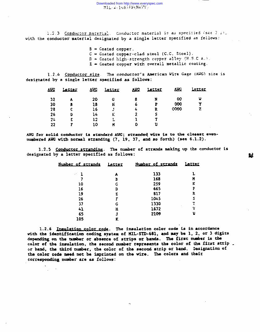
‘.3 CGRdU~~QY Fa:fTTq~. Corcdu~~orma~eri~] jg as Specitis!dI’SE~~ 1!,:.-with t’neconductor material designated by a single letter specified as foiiows:
B- Coated copper.C - Coated copper-clad steel (C.C. Steel).E- Coated high-strength co~per alloy !F5.C A.}.E= Coated copper with overall metallic coating.
1.2.h Conductor size. The conductor’s American Wire Ga~e (AWG) size isdesignatedby a sin~le letter specified as follows:
4?KZ6&LexkMLSLL4kK M?GLELQ2XS=
32 A 20” G 8 N 00 w30 B 18 M 6 P 000 Y28 c 16 J h R 0000 226 D 14 K 2 s24 t 12 L 1 T22 F 10 n o u
AWG for solid conductor is standard AUC; stranded+wire %s to the cloaemt even-numberedAUG with normal stranding (7, 19, 37, and so forth) (see 6.1.2).
1.2.5 . The number of strands making up the conductorisdesignatedby a letter specified as follows:
1710161926374165105
titter
ABcDEFGHJK
1331682596658171045133016722109
Ln~
PRsTvu
1.2.6 on color c d The tneulation color code %s in accordancewith the identificationcoding”s;stemof KXL-STD-681, and may ba 1, 2, or 3 digitsdependingon the number or absence of strips or bands. The first rnnsboris *color of tlm insulation, the second number represents the color of the first stxiP .cm band, the third nuaber, the color of the second strip or band. ksiption ofthe color code need net be imprinted on the wire. The colors ●nd theircorrespondingnumber are as follows:
Downloaded from http://www.everyspec.com
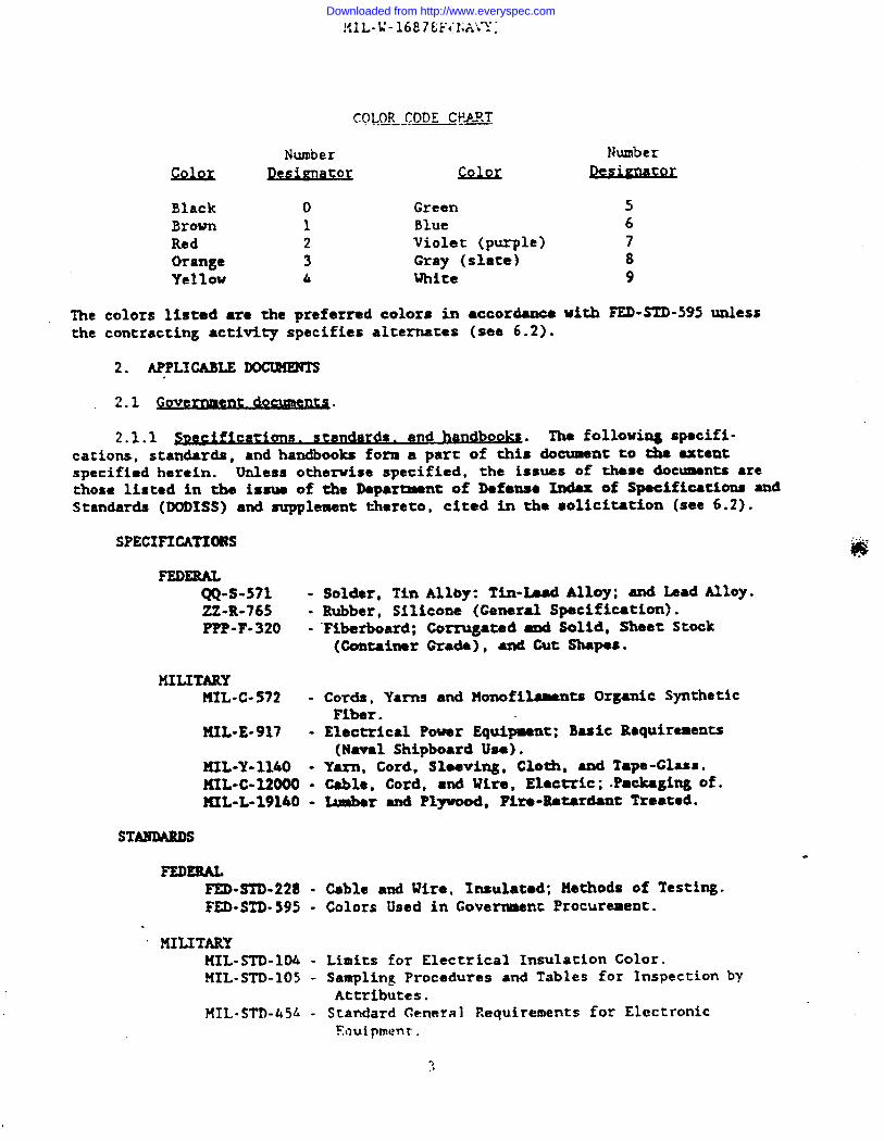
COLOR CODF CPA!!T....+- .—
Number Number
Coloc Qesimat ro Colm
Black o Green 5Brown 1 Blue 6Red 2 Violet (purple) 7Orange 3 Gray (slate) 8Yellow & White 9
The colors listed are the preferred colors in ●ccordance with FED-STD-595unlessthe contracting ●ctivity specifies alternates (see 6.2).
2. APPLICABLE ~.
2.1 ~t d-nt~ .
2.1.1 ~~ec=cari~s. sta@@s. and handbooa. The following specifi-cations, standards, and handbooks form a part of this document to the extant
specifiedherein. Unless otherwise specified, the issues of theme documents ●rethose listed in the issue of the Departmentof Defense Index of SpaoificstionsandStandards (DODISS) and supplement thereto, cited in the solicitation (see 6.2).
SPECIFICATIONS
FEDERALQQ-S-571 -ZZ-R-765 -PPP-F-320 -
MILITARY?HL.C-S72 -
IUL”E-917 -
HIL-Y-1140 -KIL-C-12000 -?IIL-L-19160-
STANDARDS
FEDERALFED=STD-228 -FED-STD-595 -
“ MILITARYHXL-STD-104 -MXL-STD-105 -
NIL-sTr)-45L-
Solder, Tin Allby: Tin-Laad Alloy; and Lead Alloy.Rubber, Silicone (General Specification).Fiberboard: Corrugate&and Solid, Sheet Stock(OontainerGrade), and Cut Shapes.
Cords, Yarns and Monofllaments Organic SyntheticFiber.Electrical Power Equipment; Basic Requirements(Naval Shipboard Use).
Yarn. Cord. SleevinE. Cloth, and Tape-Glass.cable,Ltmber
Cord, and Wi~e, Elactric;.Pa&aging of.and Plyuood, Fire-Retardant Treated.
Cable and Wire, Insulated: Methods of Testing.Colors Used in Governmcm Procurement.
Limits for Electrical Insulation Color.Sampling Procedures and Tables for InspectionbyAttributes.Standard General Requirements for Electronic%luipment.
9,,
Downloaded from http://www.everyspec.com
!’.!L-L’.lf)8!:~!iAVl;l;
(Unless othexwise indicated, copies of federal and milita~ specifications,standards. and hanobooks are available from ~he Scaridardization Documents Ordc=Desk, BLDG. 4D, 700 Robbins Avenue, Philadelphia,PA 19111-5094.)
2.2 ~on-Governmentmlblications. The following document(s) form a part ofthis document to the extent specified herein. Unless oche-ise specified, theissues of the documents whjch are DOD adopted are those listed in the issue of theDODISS cited in the solicitation. Unless otherwise specified, the tssues ofdocumentsnot listed in the DODISS are the issues of the documents cited in thesolicitation(see 6.2).
,AMEMCAN NATIONAL STANDARDS INSTIIWTE (ANSI)B46.1 - Surface Texture {SurfaceRoughness, Waviness, and Lay).
(DoD adopted)
(Applicationfor copies should be addressed co the American NationalStandardsInstitute, 1430 Broadway, New York, NY 10018.)
AHERICAN SOCIETY FOR TESTING AND HATEUIAXS {ASTM)B33 - Standard Specification for Tinned Soft or Anw+led Copper
Wire for Electrical Purposes. (DoD adopted)B 173 - Standard Specification for Rope-Lay-StrandedCopper
Conductors Having Concentric-StrandedMembers, forElectrical Conductors. (DoD adopted)
B 286 - Standard Specification for Copper Conductors for Use inHookup wire for ElectronicEquipment. (DoDidoptedl
B 298 - Standard Specification for Silver-Goated Soft or AnnealedCopper Wire. (DoD adopted)
B 355 - Standard Specification for Nickel-Coated Soft or AnnealedCopper Wire. (DoD adopted)
B 670 - Standard Specification for Bonded Copper Conductors forUse in Hookup Wire for Electronic Equipment.
B 501 - Standard Specification for Silver-Coated,Copper-CladSteal Wire for Electronic Application.
B 559 - Standard Specification for Nickel-Coated, Copper-CladSteel Vire for ElectronicApplication.
B 624 - Standard Specification for H@h-Strmgth, High-Conductivity Copper-AlloyWire for ElectronicAppllcatlon. (DoD adopted)
D 1248 - Standard Specification for Polyethylene Plastics Molding .and Extrusion Materials. (DoD adopted)
D 2116 - Standard Specification for FEP-Plwwcarbon !40Ming ●ndExmxsion Materials. (DoD adopted)
D 4066 - Standard Specification for Nylon Injection and ExtrusionMaterials (PA). (DoD adopted)
I)4314 - Standard Specification for General-Purpose,Heaw-Duty.and Extra-Heavy-Duty Crosslinked ChlorosulfonatedPolyethylene Jackets for Wire and Cable.
D4895 - Standard Specification for Poly!xtrafluoroethylene (PTFE)::esinProduced from Dispersion.
Downloaded from http://www.everyspec.com

G2L. Standard Practice ior Determining Resistance of SyntheticPolymeric Materials to Fungi. (DoD adopted)
(Application for copies should be addressed to the American Society forTes:ing md tl~terials, 1?16 .R=e Strec:, ?hiladelphie, ?A ~0103.)
NATIONAL ELECTRICALMANUFACTURERS ASSOCIATION (NEMA)UC 52 - High-Temperature and Electronic InsulatedWire-Impulse
Dielectric Testing.
(Applicationfor copies should be addressed to the National ElectricalManufacturersAssociation, Suite 300, 2101 L Street, NW, Washington, DC 20037.)
SOCIETY OF AUTO!40TIVEENGINEERS, INC. (SAE)MS 3249 - Ethylene Propylene (kPD?l)Rubber Hydrasine-Base-Fluid
Resistant 75-85. (DoD ●dopted)
(Applicationfor copies should be addressed to Society of AutomotiveEngineers,Inc., LOO CommonwealthDrive, Warrendale, PA 15096.)
/
UNDERWRITERS LABORATORIES, INC. (UL)1581 - Reference Standard for Electrical Wires, Cables and Flexible
Cords.
(Applicationfor copies should be addressed to UndarwricerslaboratoriesInc., 333 Pfingsten Road, Norchbrook, IL 60062.)
INsuLATm CASLE ENGINEEM AssocwrIoN, INc.PublicationT-24-380 - Partial Discharge Test Procedure
(Applicationfor copies should be ●ddressed to Insulated Cable Engineers$woc%ation, Post Office BOX 440, South Yarmouth, MA 026M.)
(Non-Goverrnsentstandards and other publications are noraally available fromthe organizations-t prepare or distribute tb documents. These documents alsomay be available in or through Libraries oz other informational s*ndw.)
2.3 ~. In the event of a conflict between the text ofthis doctment and the references cited herein (axcapt for rc~ted associatedspeclfloationsheets), the text of this doament takes precedence. Nothing hthis document,however, supersedes applicable laws and repd.ationsunless aspecificexemptionhas been obtained.
3.1 . The individual item requirements shall be asspecifiedhere$n.and in ●ccordance with the ●pplicable specificationsheet. Inthe event of sny conflict be~een We requirements of this specificationand thespecificationsheet, the latter shall govern.
Downloaded from http://www.everyspec.com
~,~ ~]assific~tj~~ Of y~c,~j,~emen~s, The applicable requirements are
classified as follows:
First article 3.3
Materials 3.4
Construction 3.5
Performance 3.6
3.3 First article. When specified (see 6.2), a sample shall be subjectedtofirst article inspection (see 6.3) fn accordance with 4.3.
3.& Hateri~. Materials shall be as specified herein. When a mattrial isnot specified,a material shall be used which will enable the insulated wire tomeet the performance requirementsof this specification. Acceptance of anyconstituentmaterial shall not be construed as a guaranty of the acceptance of thefinished product (see 4.5.1).
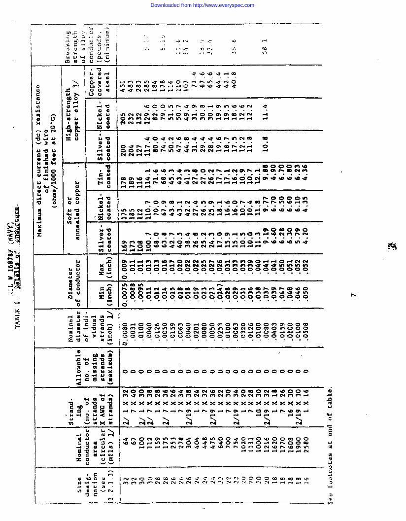
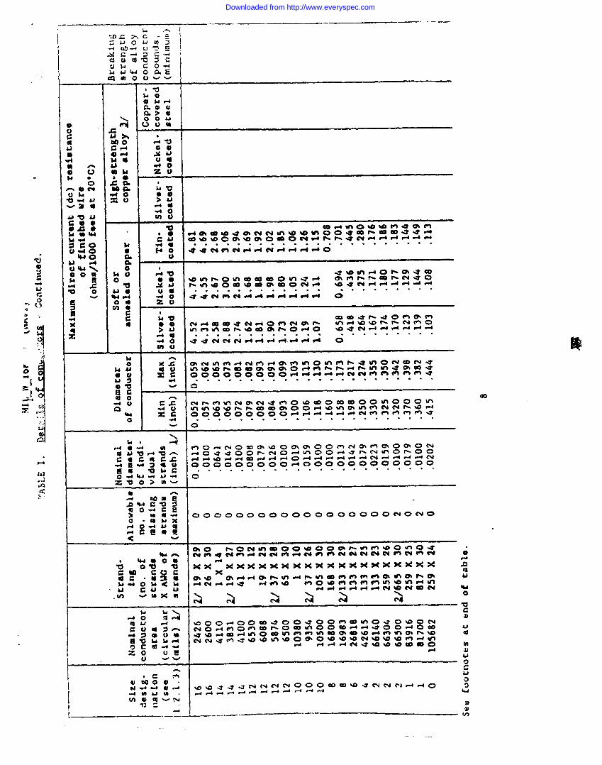
3.4.1 $onductor~. Conductorsshall be solid (see 6.1:3) or stranded asspecifiedin table I, or ●s ●pprovedby the contracting act%vity. Each SUad ofthe conductor shall be of the same composition. When coated wires are uwd,individualstrands shall be coated before stranding. Each strand shall have thesame coating. Application of metallic coating shall be permitted after strandingin accordancewith ASTM B 470, type 11. Conductors shall meet the requirementsspecifiedin 3.4.1.1 through 3.4.1.7before application of insulation.
r c~ . Tin-coatsd copper conductors shallbe in accordance with MIX B 33 for soft, annealed copper.
3.4.1.2 ~ver-coated. c~. Silver-coated,soft, annealedcopper conductors shall be in ●ccordance with ASTM B 298 with 40 nicroi.xdw(minimum)thickness of silver.
3.4.1.3 pi kel coated- c m~ctors. Nickel-coated, soft. ~aiedcopper conductor: shall be in ~ccordancewith ~TM B 355 and shall be coated with50 microinches (minimum) thicknessof commerciallypure nickel.
3.4.1.4 $il er coat d. cobwr-c~a . steel co*m- d Sllvcr-coatod,copper-cladsteelvconduct~rsshall be in ●ccordance with ciass 40A of AS%N B 501with 40 microinches (minimum)thickness of silver.
3.4.1.5 el.coated. Nickel-coated,copper-cladsteel conductors shall be in accordance ~itb A!& B 559 with 50microinches (minimnm) thicjnessof coameercialnickel.
.
3.A.1.6 ~-stre~. cower ~lov eo@xto~ . Mgh-strmgth, copper ●lloyconductorsshall be in accordancewith ASTM B 624 and table I. The strands shallbe silver- or nickel-coated in accordancewith 3.4.1.2 or 3.4.1.3 as applicable.
Downloaded from http://www.everyspec.com
—.. ———. —.A /-
I . .. ,:,.-i m.+ [)-J E I -4 .-6 .2 (X —- .- m ,-4
dao&
G90Cu
w
*
.-.
?J$=.A
. . .
.. . . . . . . . . . . . . . ●
6.---.”””
3’ . . ... “ . . “ - . . “ .’.. ‘. . .. .
0
00000009000 0000000000000
.
!-4
Downloaded from http://www.everyspec.com
.— .— —. .—k .-
. . . . . . . . . . . . . . . . . . . ..au-mfl-$ddddd d o
00000000000 Ooooooomomo
8)
Qc*
__... -_. —----
Downloaded from http://www.everyspec.com

L
1.
mas-la
s
.
uoG
0
r-5w0-4
M
.
Downloaded from http://www.everyspec.com
NIL-K- 1fJ878F<>’~lPJ”:l
?.4.1.7 Coared cower with overail metallic ~oati~- Coated coPPerconductors in which wires in the scran~ are metallically bordad together by theapplication of overall tin or alloy coating. Coating prevents strand frayingandshall be in accordance with ASTM B h70, Type 11
3.6,2 Insulation and iacket nacerti. ?laterialsshall be as specifiedin3,L.2.1 through 3.4.2.8 as applicable (see 3.1).
3.&.2.l PolWinvl chloride (PVCI. When specified (see 3.1), the insulationshall be PVC or its copolymerpolyinyl acetate, v“hichconforms to the require-ments of the applicable specificationsheet.
3.4.2.2 Eolvamide (nvlonl. When specified (see 3.1), polyamide shall be inaccordancewith ASTM D 4066 or when used in braid shall be in accordancewith typeP of MIL-c-572. “
3.4.2.3 Fluorinatedetiwlcn mroutine (m . b%en specified (see 3.1), FEPshall be in accordance with ASTM ; 2116.
3.4.2.k X ~Yt trafluoroethvlene {~ . Uhen specified (see 3.1), PTP’Eshall be in •cc~rda~ce With ASTM D 4895.
3.4.2.5 Polvethvlenq. When specified (see 3.1), polyethylene shall be inaccordancewith type 11 of ASTM D 1248, except colored material can be used.
3.4.2.6 ~. When spacified (see 3.1), silicone rubber shall be *in accordance with class 2a, grade 25, 40, or 50 of ZZ-R-765.
3.4.2.7 Chlor sulfon ted vol~ne = When specified (see 3.1),CSPE shall be in ac~ordancswith ASTM D 4314. -
3.4.2.8 5thv~-moDvlene die~sr~ When specified (see3.1), EPDH shall be in accordancewith SAEAMS 3249. “
3.4.2.9 d material. Additional materials shall be acceptableforchanging the above materials if the crosslhked final product meets therequirementsof the ●pplicable Specification sheet (see 3.1).
3.4.2.10 Other mat-. When other materials are specified,”theyshall becertifiedvirgin materials containbg no additives, except those requiredsswetting agents, pigmentationsfor color, and lubricants wed in ext~ion.
3.4.3 ~. When speclfled (see 3.1), braids shall be synthetictextilein -accordancewith type P of ML-C-572, or glass yarn in accordance with MXL-Y-1140,as specified (see 6.2).
3.5 Cons~tion.
3.5.1 Conductors. Stranding shall be as specified in table I afterinsulation. The conductorsshall be round in shape, uniform in cross seccionandfree from flaws, scales and other imperfection.s.Unless ozhelwise specified(see6.2]. the method of stranding for AUG sizes No. 32 (single cmduccor) through No. ~“’
Downloaded from http://www.everyspec.com
!41L-b’-l6878F+/uAvy)
10 (105 stranding) inclwive, shall be at the option of the contractor. Rope laystranding only shall be used for AUG sizes No. 8 (133 strandzng) and Larger.Length of lay of finished, stranded conductors shall be in accordancewith ASTM B286 or ASTM B 173, as applicable.
3.5.2 Jnsulation, A tight-fitting, continuous coating of insulation shallbe added over the conductor and shall be cured, processed, or maintained toprovide for accurate centering of the conductor (see 3.6.6). The insulationshallbe free from splinters, blisters ●nd other non-homogeneitiesvisible to the normaleye. The insulation shall be constructed to be readily stripped from theconductor co that the conductor is clean for soldering or crimping. A cleanconductor shall have no particles of insulation visible to the naked qe.
3.5.3 ~. When specified (see 3.1), a closely voven braid shall beapplied over the insulation. Braids shall be saturated or filled and coated withfungus-,heat-, flame- and moisrure-resistant lacquers to a smooth finish whichshall minimize fraying at the cut en& under conditions incident to handling whilebeing installed and during normal sexvice. Coatings shall be sufficientlytranslucentso as not to impair the visibility of any underlying color code of thebraid materials when strips are specified. Color carriers used in braM.s shall beone carrier (minimas) revolting in the same direction and shall be composed ofsynthetic textile or glass yarn (see 3.4.3). The braid shall not increase theoutsi& diameter of the finished wire by more then the maximum amount specified intable II.
Diameter over insulation Diameter f.morease(inch) (inch, maximum)
0.125 or less 0.0150.126 - 0.250 0.020
Greater than 0.250 0.03s.
3.5.& &ckeq. When specified (see 3.1), a jacket shall be extruded over theinsulation.
3.5.s ~. colors shall be in accordeaoe withmI.L-sTD-M4; class 1,●xcept pastel colors shall be •coep~le wham oroealimkiag is dome by irradiation.When Insulation surfaces have bean oolor ooded wi~ laks or dyes;theyshall benonconductive,permanently fast and shall not change, fade, rum, or blead WIMnused in direct sunlight and within the specific temperature rating of theinsulationmaed.
3.5*5.1 ~. When specified (see 3.1), the length of lay ofcolored stripes shall be as specified in table XII.
Downloaded from http://www.everyspec.com

TABLE 111, Lenzth of lay of Strin~.
Diameter over finished wire bngth of lay(inch) (inches,maximum)
0.000 CO 0.083 1.000.084 to 0.110 1.500.111 and larger 2.00
3.5.6 $Dlices. Splices shall not be ma& in a szrxnded conductor as a whole;however, individual strands and solid conductors may be spliced. Splices shall bemade by electro welding or brazing with silver composition solder in accordancewith QQ-S-S71. “
3.6 perfo~ e. Unless otherwise specifiedherein, all requirements(see3.6.1 through 3.6.16) shall be met on finished wire.
,
3.6.1~ulation flaw~. After application of the primary insulation, thewire shall withstand the spaxk test or ‘Impuse dielectric test voltage asspecified (see 3.1) without breakdown. Afzer applicationsof braids or Jackacs,the finishedwire shall withstand the spark test or the impulse dielectrictestwithout breakdown <see 4.5.2.1 and 4.5.2.2).
3.6.2 The wire shall withstand thespecifiedvoltago for 1 minute (mixdua) wi&iout breakdown (see 3.1 and 4.S.3).
3.6.3 . The insulation resistance shall be not lessthan the value ~pecified (see 3.1 and 4.5.4).
3.6.h ~. The conductor resistance of the finishedwireshall be not greater then the value specified (see 3.4.1 and 4.5.5).
3.6.5 ~oldben~. Specimens”shallreveal no readily visible cracks in theinsulation●nd shall pass the dielectric withstanding voltage requirementsasspecified (sm 3.6.2 and 4.5.6}.
3.6.6 Conc~. The concentricity of finfshedwlre insulationend theprimary i.asulationof dtl-leyered Lneulation or jacket, SW be 70 percent(minimum). The faflure of the concentricf~ of any cross-section shall constitutefailure for the entire speciaen (see 4.5.7).
3.6.7 (w%re ti~ The surface ..res~s~e shall be 5 Dsgoba-i.xIches(minimum). A surface resistance of 1SSS ~1000 megohm-inchesshell not change by mora then SO percent from the inicf.almeasuredvalue after the application of the high potential end remeasurementOf
surface resistance (see 3.1 and 4.5.8).
3.6.8 Urariback test (nFE insulation Specimens shall reveal no
cracks when visually examined and shall pass the dielectric withstanding voltage
requirements as specified (see 3.6.2 and A.5.9). ... .
12
Downloaded from http://www.everyspec.com

MIL-U-16878F{NAVY)
3.6.9 Heat resist nnce. Specimens shall reveal no cracking or delaminationof the insulation (and jacket when applicable), no ex*tion of we i~~tionthrough the braid in constructions incorporating braids, no readily visibledefects in any of the wire component parts (slight discolorationafter aging isconsidered normal ●nd acceptile) and shall pass the dielectric viths-ingvoltage requirements ES specified (see 3.6.2 and 4.5.10). .
3.6.10 -ablJJ@. Insulation shall not burn for more than the specifiedtime and the flame shall not travel more than the specified distance nor releaseflaming particles that ignite combustible materials4.5.11).
3.6.11open up over
3.6.12
SihKhMQ. Insulation shall not flarethe bent portion, nor shrink back more
~. Insulation elongation andchange more than specified (see 3.1 and 6.5.13).
in its vicinity (see 3.1 and
away from the conductor northa.nO.125 inch (see 4.5.12).
tensile strength shall not
3.6.13 lation tensile strene* ihe minimum tensileinsulation shall”be as specified (see 3.1 and 4.5.14).
3.6.14 ~. fie~*uIse longationofas specified (see 3.1 and 4.5.15).
screngtb of
insulation shall be
3.6.15 ~. A“iIIi~ Of 125 cycles ‘f ‘hemandrel shall not remove the printed marking or color code stripe from the wires~le (see 4.5.16).
3.6.16 ~. All nonmetallic materials, including compoundedmaterials, that are not fungus-inert in ●ccordance with MIL-STD-&54 shall bSfungus resistantas specified (see 3.1 and 4.5.17).
3.6.17 ulati~ tl~ (PTFE extruded ~on O-The circumferentialelongation for m ext~d insuhtim shall not be less than
.
the average percent for conductor size of y~le IV (sea 4.4.3.1.3 and 4.5.19).
T=~. ~
Conductor size Percent (Average)
28 to 16 20014 to 12 1.5010 to 8 100
3.6-1; ~.voltage tests on the lead wire. The
equal to.20 percent greater than thebut shall not exceed the required acshall be as specified in 4.5.20,
Test shall be ma& prior to the ●c and dcapplied voltage shall be raised to ● valueminimum partial-discharge extinction levnltest voltage for the lead wire. This test
1’3
Downloaded from http://www.everyspec.com
MTL-U-lb87f?.F<NAVk’)
3.7 Jdentifjcation of mroduc~. Unless otherwise specified {SW 3.1 and 6.2),finishedwire shall be identifiedby a printed marking applied to the outersurface of the wire or visible through the outer surface. The printedidentificationshall be at intenals of 9 to 60 inches oeasured from the beginningof ~ne =oq~ete ~ark~ng to the ~eg~nn~ng of the succeeding complere marking and
shall consist
(a)(b)(c)(d)(e)
of the following:
K16878/* (* applicable specification sheet).Conductor material as identified per PIN number.Conductor size as Identified per PIN number.Voltage ratingManufacturer’s supply code designation.
Printingshall be of a contrastingcolor (black or white is preferable) in apermanent ink or dye. Idencificacionprinting shall be applied with the verticalaxis of che prinC8d characters either crosswise or lengchwlse on the wire when thenominal diameter of che wire is greater than 0.050 inch. Identificationprintingshall be applied with the vertical axis of the printed characters lengthwiseonthe wire when the nominal dismecer of the finished wire is 0.050 inch or smaller.Printed characters shall be complete and legible to the naked eye.
3.8 Uorkmanshi~. Wire shall be free of kinks, abrasions, and cracked orpeeled surfaces. Wire shall be a uniform and consistent product and shall be freefrom defects which will adversely affect the serviceability of the product.
3.9 ~. Materiala specified herein for the construction of the p
insulatedwire shall be selected to provide maximum resistance to burning. Thecombustionof these materials shall not create ● concentration of toxic gases thatexceed maximum concentration levels specified in HIL-E-917, table I (see 3.6.10,4.5.11 end 4.5.18).
Uith respect to toxici~ levels of wire inspected to this specification,it SS the
Goverment’s intent to accumulate data from the testing of first article samples.This data will be compiled and evaluated to establish ●ppropriate concentrationlevels of toxic gases for future acceptable maximum concentration levels.Contractorsare requested to provide such data with repect to their productsfollowing first ●rticle testing. This date will noc be used for the rejectionof~ prkct first article testing.
4. wm--=-=~sx~s .
4-1 ~. Unless otherwise specified in thecontract or purchase order, the contractor is responsible for the performanceof .●ll inspection requirements (examinations●nd tests) as specified herein. Exceptes othertrlsespecified in the contract or purchase order, the contractor BSY usehls own ox ●ny other faciliths suitable for the performance of the inspectionrequirementsspecified herein, unless disapproved by the Government. TheGove~ent resezwes the right to perform any of the inspections set forth in thisspecification where such inspections are deemed necessary to ensure supplies and
scmices cmfom cc prescribed requirements.
.
Downloaded from http://www.everyspec.com
I’lIL-W-16878HNAVS)
4,1.1 ~esnonsfhilftv for comolJ.ante. All items shsll meat all requirementsof sections 3 and 5. ‘X’heinspection set forth in this specificationshall becomea part of the contractor’s overall inspection system or quality program. Theabsence of any inspection requirements in ~e specification shall not relieve thecontractorof the responsibility of ensuring that all products or suppliessubmitted to the Government for acceptance comply with all require-n~ of thecontract. Sampling inspection, as part of the manufacturing operations, is anacceptable practice to ascertain conformance to requirements,however, this doesnot authorize submission of known defective material, either indicatedor actual,nor does it conseitthe Government to ●ccept defective oateri.al.
4.2 Classificationof inspections. The inspection requirementsspecifisdherein are classified as follows:
(s) First ●rticle inspection (see 4.3).(b) Quality conformance inspection (see 4.4).
4.3 ~. First article inspection shll co~ist of allthe tests (groups A, B, and C of table V) and examinations of this specification.
4.4 ~. Quality Confoz’ma=t inspectionshallconsis~of the inspections Msted in table V (groups A and B) and as specified in4.5. Quality conformance shall be performed on every lot of wire procured underthis specification.
4.4.1 ~. Unless ofierwise specified (see 6.2), an inspectionlot shall consist of ●ll wire of the same part number, produced under essentiallythe same conditions, and presented for.inspection and shfpment ●t one time.
4.4.2 Wt of vro~ . The unit of product for determining lot size.forsampling shall be the quantity of wire offered for inspectionon one coil, O*reel, or one spool, ●s applicable.
4.4.3 ~. Group A inspection shall consist of the tests. specified in table V. These tests cannot be performed on the finished wire ●s
submitted for Inspection; therefore, they shall be performed ●t the mostappropria~ stage of th~ manufacturing operation. The tests shell be performedonevery lot of wtre acquired under this specification.
. . . ,-, -------- ... . .. . . . . . .
4.4.3.1 <. Sampling for grk~ A’inepectian shell”b~:aa specified in4.4.3.1.1 and 4.4.3.1.2.
4.4.3.1.1 ●nd al examina~ (extent f~ Threesamples representative of the inspection lot shall be selected (see 6.6.1.1).
.
4.4.3.1=2 ~. Wire provided under this specificationshall besubjected to the appropriate insulation flaws test as specified in 4.S.2.Insulationbreakdowns resulting from this test and ends or portions net subjectedto the test, shall bc cmked or cut out of the finished wire.
Downloaded from http://www.everyspec.com
ML-u- i6876F4NAW)
.-[extxuded ~FEJJISUL@ cion oniyl. Wire
4.4.3 .1.3 Circumfe rential elon~ation
insulationshall be sub~ected to the circumferential elongation test as spec~fled
. .? y
in fb.5.19.
&.J+.& ~rouD B . Croup B inspaczion shall consist of the tests
specified in table V. The sample shall be selected from inspection low that have
passed group A inspection.
L.fb.f).l M ecimens. Smples for group B inspectionshall be 26 foot(minim~] lengths for the insulation resistance test. and unless othenfise
specified herein, for all other test shall be the length specified in rhe
applicabletest method. Only one specimen for each test shall be taken from any
one sample unit.
TABLE V. First fIcicIs$ anda~w ~i.
rons.
Inspection
Group A
Visual ●nd mechanicalexaminationInsulationflaws:SparkImpulse dielectricCircumferentialelongation .
Group B
Dielectricwiths-~ngvoltageInsulationresistanceConductor resistanceCold bendConcentricitywrap backInsulation tensile strengthInsulationelongationliarkingand stripe durabili~
Group C
Surfaoe resistxbceHut r8si8tamceFleusaabili~ShrinkageHeat ●gingFungus resistance
Requirement I
3.1, 3.4, 3.4.1, 3.5.3.5.6, 3.7 and3.8
.
3.6.13.6.13.6.17
3.6.2
3.6.33.6.43.6.53.6.63.6.83.6.133.6.143.6.15
.
3.6.7. 3.6.9” ;..
3.6.103.6.113.6.123.6.163.9
Test Method
4.5.1
4.5.24.5.2.14.5.2.24.5.19
4.5.3
4.5.46.5.54.5.6&.5.74.5.94.5.14f4.5.154.5.16
-
4.5.17
Toxicity4.S.18 4
4.5.4~4.5.104.5.114.5.124.5.13
ih
Downloaded from http://www.everyspec.com
MIL-X-16878F<NAW)
TABLE 1’ First artjc~e amd qu~l; tl,conformance immections.
Inspection Requirement
I
Test method Classificationof defect
Group A .
Visual and mechanical
examination 3.1, 3.4, 3.4.1,3.5, 3.5.6, 3.7and 3.8 L.5.1 tlajor
Insulation flaws: 4.5.2
Spark 3.6.1 &.5.2.l CriticalImpulse dielectric 3.6.1 4.5,2.2 CriticalCircumferentialelongation 3.6.17 4.5.19 Hajor
Group B
Dielectricwithstandingvoltage 3.6.2 4.5.3 criticalInsulationresistance 3.6.3 &,s.fb KajorConductor resistance 3.6.4 4.5.5 MajorCold bend 3.6.5 4.5.6 HajoxConcentricity 3.6.6 4.5.7 CriticalUrap back 3.6.8 4,5.9 Criticallnaulationtensilestrength 3.6.3.3 4.5.14 CriticalInsulationelongation 3.6.14 4.5.15 CriticalMarking and strip
●
durabili~ 3.6.15 4.5.16 Minor
Group C
Surface resistance 3.6.7 4.5.8 nejorHe&t resistance 3.6.9 4.5.10 Majornamebiliq 3.6.10 4.5.11 !linorShrinkage 3.6.11 4.5.12 Uajor
Heat Aging 3.6.12
_ ~i%~e
4.5.13 Major3.6.16 4.s.17 Minor
Toxicity 3.9 4.5.18 “ --Z/ ‘
L/ Crieical defect - A defect likely to result in hazardous or unsafeconditions for-indivhhals; or is,likely to prevent -parfomsnce of tie tactical fimction of a major enditem such as an aircraft cormaunicationssystem, ormul.npart thereof.
hjor defect - A defect, other than critical, likely to result Infailure or reduce materially the usability of theproduct for its intended purpose.
17
Downloaded from http://www.everyspec.com
?llL-W-16878F<NA~)
Minor defect - A defect not likly to reduce materially the usabiiitYof the produc~ for its intended purpose. or is adeparture from established standards having littlebearing on the effective use or operation of theproduce.
A.4.4.2 $=n~inr Dla The sampling plan shall be in accordancewithF!IL-STD-105for special in~pectionlevel S-2 (see 6.6.2). The sample size shallbe based on the inspectionlot size from which the sample was selectedfor group Ainspection.
b.4.4.3 Re~ ctee d lots. If an inspection lot is rejected, the contractor mayrework it to correct the defects, or screen out the defective units and resubmitfor reinspection. Resubmittedlots shall be inspected using tightenedinspection.Such lots shall be separate from new lots and shall be identifiedas reinspected10CS.
L.4.L.4 Disposition of sanlDleun its. Sample units which have passed all khegroup B inspections may be delivered if the lot is accepted and the sample unitsare srlll within specifiedelectrical tolerances.
4.5 tiethods f insvectioq. Inspections shall be performed as specified in6.5.1 through 4.5.~7,
*4.5.1 .ex~atlon . Finished wire shall be examined to
dete~ine that the materials,physical dimensions, constmction, splices.-rking,and workaanahip ●re in accorda~e with the applicable3.4.1, 3.5, 3.5.6, 3.7, and3.8 respectively).
4.5.2 ~. Testing for ix=ulationin4.5.2.l tttrough4.5.2.2, as applicable.
requirements (see 3.1, 3.4.
flaws shall be as specified
L.5.2.1 ~. The spark test shall be performed in accordancewithmethod 6211.1 of FED-STD-228 at ● rate that subjects each point on the tire to 9cycles (Rinimsm)of voltage at 60 hertz (~) or 12 qc19s (ninkxb) of volt$ge ●t3000 Hz. l%e tast voltage shall be as specified (see 3.1).
4.5.2.2 ~. Tba impulse dielectric test shall be inaccordancewith NEMA UC 52, except tie i~~at~~ sM1 be reaovad or Mentlfiedfor subsequent removal fox a ●infmm of 3 inches oneacb side of tiepoi.nt ofdielectric failure. The test voltage shell be as specified (see 3.1).
4.5.3 ~ Vo~. Om * of ilmzlationshll be “removed from each eml of th. apec~n and the specimen shall be ●t~cbed to anelectrlc lead. The specimen shall be imetsed in ● 5 percent (by weight) solutionof sodim chloride in water at 20 to 25*c, except the uninsulated ends, plus 1.Sinches of fnsulaced wire ●t each ●nd, shall be exposed to the air. ARerimmersion for 1 hour, the voltage specified (see 3.1) at 60 Hz shall be appliedbetween the conductor and an electrode in contact with the liquid. The appliedvoltage shall be unifornly increas~d from zero to the specified peak voltage in 30seconds, maintained at that voltage for a period of 1 minute and uniformly reduced-.,
18
Downloaded from http://www.everyspec.com
KIL-G-Ma7t.F{liAvYj
>.to zero in 30 secon&. Wire shall meet the requirements specified in 3.6,2.
4.5.4 ~. The insulation resistance test shall beperformed on the same wire sample used for the Dielectric Withstand Voltage Test(4”.5.3)and shall be in accordance with method 6031 of FED-STD-228 vith thefollowing exceptions:
(a) The test voltage shall be 500 +/- 5 volts direct current (Vdc)applied for 60, plus 5, minus O seconds from the time it is
reached.(b) The specimen shall be at least 26 feet long.
(c) The stf.rrerneed not be used.
Wire shall meet the requirements specified in 3.6.3,.
4.5.5 Conductor re~ The conductor resistance test shall beperformed in accordancewith method 6021.1 of FED-sTD-228. Wire shall meet therequirementsspecified in 3.6.&.
4.5.6 gold be@. The cold bend test shall be performed in accordancewithmethod 2011 of FED-STD-228 with the following exceptions:
(a)
(b)
(c)(d)
(e)(f)
(g)
(h)
(i)
Specimen length shall be 12 inches, plus length required forwrapping on the mandrel.Specimen shall be stripped 1 inch on each end down to the bareconductor,Usmdrel size shall be as spec%f%ed (see 3.1).Mandrels of less than 3-inch diameter shall rotate ●t ● rate of1S +/- 3 revolutions per minute (4.0 +/- 0.2 seconds perrevolution).Specimens shall be conditioned as specified (see 3.1).Specimens for which a 3-inch or larger mandrel is specified shallbe subjected to a 180-degree bend over the mandrel, Chen -o-dand bent 180 degrees in the opposite direction over the mandrel.Specimens for which a mandrel less than 3 inches in diameter isspecified shall be subjected to at least three close turns of wireon the mandrel and rewrapped in the opposite direction in asimilar msmrum.
The specimen shall be removed from the mandrel and e~inadwithoutstraightening.
Wire shall be ilwaersed,except for 1.5 inches on ●ach end, for 1hour at 30*C (maximum).After 1 hour, while ieeaersed,wire shall be subjected to thedielectric withstandi.ngvoltage test specified in 4.5.3.
Wire shall meet the requirements specified in 3.6.S.
4*5.7 ~. The concentricig of the insulation shall be messtiedon a cross-sectionof the finished wire at 10X magnification. If the vireconstruction includes additional layers over the primary insulation, separatedeterminationsshall be made tor the primary insulation and finished wire. Inmaking the determination, the minimum thickness of the primary insulation or
Downloaded from http://www.everyspec.com
finished wire shall be located and measured in the cross-section. The maximumthickness of the pri=ry insulacior,or finished bi~e wall shali be located anameasured in the same cross-section. The percent concentricity is 100 times theratio of the mi* measurement to the corresponding maximum measurement. Threecross-seccions shall be measured in each specimen. Wire shall meet therequirements specified in 3.6.6. The failure of the concentricity of any cross-section shall comtitute failure of the entire specimen.
h.5.8 . Surface resistance
shall be measured in accordance with method 6041 of FED-STD-228 with the followingexceptiom- and additio=:
(a) Two 0.250 inch electrodes consisting of ring-type metal foil shallbe allowed.
(b) Electrodesshall be attached near che center of the specimenlength.
(c) The maximus potential shall be 200 to 500 Vclc.(d) Specimen shall be conditioned at 25 +/- 5-C, and 95 percent
relative humidity.(e) If the initial surface resistance is greater than 1000 megotus-
inches, the test shall be considered complete.
Wire shall meet the requirements specified in 3.6.7.
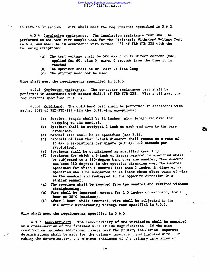
4.5.9 Ura~ back test (mm insulation onlv~. The center portion of a 12-inch (minimum) length specimen of finished wire shall be t@htly wound back oni.ts*lffor a minimum of four close turns (see figure 1). The specimenshall thenbe placed in an oven and heated for 2 hours at 307 +/- 5°C. At the end of thisperiod, the specimen shall be examined (without magnification) ●nd subjactedtothe dielectric withstandingvoltage-test specified in 4.5.3. Wire shall meet therequirements specified in 3.6.8.
.-.
MCURE 1. UraD back tes~.
4.5.10 Heat resistancq. Specimens of finished wire shall be 12 inches long,plus the length required for winding on the mandrel. The specimen shall besubjected to the specified temperature (see 3.1) for the following duration oftesting:
.,.,
. ..
Downloaded from http://www.everyspec.com
MIL-W-16878F{NAVY)
(a) PE insulation 48. plus 1. minus C)hours.(b) All (except PE, CSPE, EPDM) 96, PIUS 1, minus O hours.(c) CSPE insulation 2k0, plus 1. minus O hours.(d) EPDM insulation 240, plus 1, minus O hours.
The specimen shall then be removed from the conditioning chamber and ●llowed toreturn to room temperature. If strmd sealer has been used to make a watertightconstruction,the sealing compound shall not drip from the ends of the wire. Melength of exposed conductor, if any, at each end of the specimen shall beconsideredas shrinkage of the Inaulaclon. In no case shall the shrinkage ●teither end exceed 0.125 inch. Following the oven aging, ●nd unless otherwiserequired in the applicable specification sheet, specimens shall be wound tightlyaround a mandrel approximately (but not less than) three timesthe overalldiameter of the wire for five close turns and removed as ● helical coil. Noreadilyvisible defects shall result from this heating and coiling. The coiledsections shall be Immersed (except for approximately 2 inches ●t each ●nd) for 1hour in tap wscer at room temperature, and shall then withstand the dielectricwithstandingvoltage test specified in 4.5.3 for 1 minute. Wire shall meet therequirementsspecified in 3.6.9.
L.s.11 ~ Testing for insulation flammability shall be asperformed in accordance with VW-1 flame test ❑ethod of lJLStandard 1581. Wireshall meet the requirements specified in 3.6.10.
6.5.12 ~. Finished vire shell be tested in ●ccordance with method8231 of FED-STD-228. Insulation shall meet the requirements specified in 3.6.11.
4.5.13 ~. The heat aging test shall be performed inaocordancewith method 4031 of FED-sTD-228 with the following..exceptions:
(a) Temperature shall be as specified (see 3.1).(b) Duration of hating shall be 96, plus 1, minus O hours.(c) Specimens shall be left at room tempera-e from 16 to 48 hours
before elongation and tensile strength tests are performed..
Insulationshall meet the requirements specified in 3.6.12.
4=5-14 ~. The insulation tensile strength testshall be performed in ●cco~e W* ~~d 3021 of ~-~-228, ●xcept that the
rate of travel of pmrer ●cwted grip shall be 2 inches (mimimum) amd20imcheamaxima) per minute travel. Insulation shall meet the requirements specified in$.6.13.
4*5*15 ~* The ●longation test shall be ~xfommed inaccordancewith method 3031 of ~.STD-228, except that the rate of travel Ofpower actuated grip shall be 2 inches (minimum) and20 inches (maximum) per minutetreve1. Insulation shall meet the requirements specified in 3.6.14.
4.5.16 and stri~e durabilitv. ?%1s test shall determine the abilityof printed information on insulating or jacketing meteria]. to remain legible inthe presence of repeated abrasion.
21
Downloaded from http://www.everyspec.com
L.5.16.1 $neclme~. The specimen shall consist of a piece of completed wirewhich shall have suffieienr Aength for use in the testas specified in f+.S.16.3.This test shall not apply to constructions which have clear jackets or braid overthe primary insulation.
4.5.16-2 ~. Apparatus shall hcl@s an ●bradin~machhewhich shall support and secure the specimen so that it is straight and horizontal,and which shall abrade the specimen printed identificationby means of a motordriven. crmnsversely reciprocating steel pin. This steel pin shall have ●
diameter of 0.025 ~ 0.001 inch where it ●brades the specimen, and shall have asurfaco roughness of not less than 2 aicroinches, in ●ccordance with ARSI B66.1.(A selected sewing needle DSy satisfy these requirements.) The steel pin shall behorizontal and perpendicularto the specimen axis, shall ride along ~Ae top of thespecimen, and shall be weighted to bear down on the specimen with a force of 1
plus 1/16, minb O pound for wire size number 24 or larger, and 1/2 plus 1/8,minus O pound for wire size number 20 or less, at all times during the test. This 4pin shall be reciprocatedat a rate of 60 ~ 2 cycles per minute, so that the pin :..
is drawn ●long the specimen for a distance of 3/8 plus 1/16, minus O inch in eachdirection (3/4-inch minimum total excursion) during ●ach cycle. The abradingmachine shall incorporate an automatic counter to total the number of times thatthe specimen is abraded by the steel pin during the test.
k.5.16.3 R ocedur~. The specimen shall be wiped with a clean, dry cloth toremove any lubricant or dirt, and shall be secured in the abrading machine withthe specimen printed identification facing upwards, i!%where it is co be abraded by “the steel pin. The automatic counter shall be set initially to zero. The●brading machine motor shall then be turned on, allowing the steel pin torec%procmte and abrade the specimen printed ideatlflcationeither until theprinted identificationis no longer Itgible in &e ibraded region, or until notless than 125 abrasive cycles (250 strokes) have been completed, whicheveroccursfirst. The number of abrasive cycles completed shall then be noted. This testshall next be repeated four more times (five times COCS1), subjecting● freshportion of the specimen printed identlficacf.onco abrasion each time.
4.5.16.4 Obsevatl~. Specimen failure shall be const-ed if the medianvalue of the number of abrasive cycles co~leted during ●ach of the five tests isless than 125.
k.s.17 r sisu~ The fungus resistance test shall be performed inaccordancewith ASTM ; 21. Ui~e shall meet tho requirements specifiedin 3.6.16.
4.5.18 ~. Toxiciv concentration levels for the finishedwire shall ,not mxceed the values specified in ML-E-.917, table 1, in ●ccordancewith the - ‘methods apecl.fied(see 6.4). Wixo shall meat tk requirements specifiedin 3.9. ‘
4.5.19~lon ~. This test Esthod measures the elongation of ● thin ●lug ofluireinsul~tion in the circumferential (radial) direction. The wire insulationslugradially elongated by axial movement
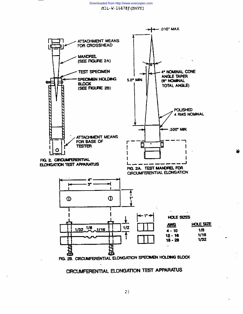
slug. Tho werall test apparatus isinsulation shall be removed from the
of a capered cone through the stationaryshown in figure 2. A 1 to l-1/2-inchslugconductor. Care shall be taken to prevent
~’J
is
of.../;.
1
Downloaded from http://www.everyspec.com
HZ L-W-16878F(N.%:JY)
+- .OIO-MAX.
~1
(SEEnGmE 29)
/A17ACt+MEW ME-FOR BASEOF
fmz~EK)NGA” TEST APIWUii
r
B
—— —-. 1
!- 1
I 1“I 1L ------ --- -1
FIG 2A. TEsTMAMmELmRcmtnwmmnu -ATl~
CKXMFERENTIAL ELONGATIONTEST AFPARA~
??J
Downloaded from http://www.everyspec.com
~c~atchir.g,crirr~lng srretc}lirg or otherk’ise damaging the insulation. mediameter of the exposed conductor should be measured to the nearest 0.001 inch.
Cut five test specimens 0,125 inch ~.02 inch in length from the insulation slugusing A sharp razor blade or an appropriate sample preparation fixture. Both endsof the cesr specimens shall ‘becut square, Slide a specimen onto the cone untilit just touches the edges of che cone. The cone should be attached to.a moveablecrosshead as shown in figure 2a. Position the specimen holding blockperpendicularto the cone as shown in figure 2b. Align the cone tip and theappropriate sized hole of che specimen holding block for the wire size beingtested. Move the cone through the stationary specimen at ● uniform speed of 20
k.2 inches/minuteuntil the specimen ruptures. Determine the length of the conethat has passed through the specimen causing rupmre. The percent circumferentialelongation (% CE) is calculatedas follows:
(2 x J.x Tan@ - CO~%CE-
CDx loot
L- Cone length required :0 rupture specimen (inches)
CD - Conductor diameter (inches)# - Measured cone angle taper (degrees)2 x L x Tan@ - Inner diameter of the test specimen at rupture (inches)
Five specimens shall be tested and the average value of the five specimenscalculated.
4.5.20 partial disa (Corq@ le ●l test .Sample.of completed Insulatec’wire shall comply with the minimum dischar~e (coro&) level specified in ASTllD2802 when tested in accortince with the procedures of ICEA PublicationT-24-380.
4.6 Znsnection of Sample packages and packs, and the inspectionof the presentation, packing and marking for shipment and storage shall be inaccordance with the requirements of section 5 and
5. PACKAGING
(The packaging requirementsspecified hdrein
the documents specified therein.
apply only for direct Governmentacquisition. For the extent of applicability of the packaging requirementsofreferenceddocuments listed in section 2, see 6.5.)
5.1 Gene*.. .
5.1.1 put-urn. Unless otherwise spmcifiod (see 3.1 end 6.2), the wire shallbe furnished in continuous lengths of 500 to 1000 feet coiled, on spools or reels -●t the contractor’soption. HO more than 25 percent of the total fooqge of qone wire part or identifyingnumber (PIN) (see 6.7) shall he shipped in lengthsless than minimum. See appendix B for PTFE length requirements.
5.2 e reuuirementq. The packaging of5.1.1), shall be in accordance with tIIIL-C-12000foror C), the level of packing (A, B, or Cj, includingacquisitioning options therein, as specified (see 6
2Ll
wire, put-up as specified (seeche level of preservation (Amarking and packaging2). ln addition, for Navy
Ii!!
Downloaded from http://www.everyspec.com
zcquisi:ions , tkke fol~owing applies:(a) Pam ffre retardant re~. uiremenc s.
(1) J.umber and D1vwood . ken specified (see 6.2), all lumber andplywood including laminated veneer material used in shippingcontainer and pallet construction, menbers, blocking,bracing, and reinforcing shall be fire-retardanttreatedmaterial conforming to MXL-L-19140 as follows:
Level A ●nd B - Type 11 wmather resistant.Category 1 - general use.
Level C . Type I non weather resistant.Categorv 1 - general use.
(2) ~iberboard. Vhen spticified (see 6.2), fiberboard used in theconstruction of class-domestic, non-weather resistantfiberboard and cleated fiberboard boxes including interiorpackaging forms shall meet che flame spread index andspecific optic density requirements of PPP-F-320 and
, amendments chereco.
(b) ~ial~ . Unless ochemise specified (see 6.2), each coilspool or reel, as applicable, in addftion to the MIL-C-12000marking requirements, shall be marked wi.chthe following:
[:; ~Ncification sheet title and date..
(3) !fanufacturer’s name or logo.(4) Bar code.
6. NOTES
(This section contains information of a general or explanatory nature thatmay be helpful, but is not mandatory.)
6.1 ended USQ. The single conductor wire covered h th~s specification1s intended for use in lead wire and internal wiring of electrical and electronicequipment and switchboards.
6.1.1 ~ulatioq. Precautionary considerations should be givenwhexasolocting thin wall insulated wire. Wire having thin wall insulation of0.007 inch thickness or less 1s intended for limited low voltage ●pplications. is -relatively frag{la,●asily damaged, and should not be used where mechanical stressor abrasive ●nvironment nay exist. Use of this wire may not be ●ppropriate incircuits requiring the highest degree of reliability. In order to appearconsistent, the temperature rating is the same as assigned to heavier walls of thesame dielectric material. However, care should be taken during installationtoavoid damaging zhe dielectric wi:h hot Solderirtg iron or mechanical abuse and to
ieave no residual physical strain cm the dielectric wall, because plastic flow mayresult in failures.
Downloaded from http://www.everyspec.com

F’!I1..L’-16U7W(NA1T)
6.i.2 ~Lrsndec? ccxk:c: zize desirnat icms. The conduc:or sfzes and the
corresponding size designations of this specification ●re in accortincewithestablished usage for stranded. copper conductors for hookup wire in the
electronicand aircraft industries. These Eizes and size designationsare notidentical with AWG sfzes for solid wire and stranded wire. The diameter andcross-sectional areas of ~he stranded conductors of this specification are, inmost sizes, only roughly approximate to those of AWG solid conductors of the same
numerical size designation.
6.1.2 $alid conductc~. The use of solid conductors should be cautioned.Usage should be limited to lengths less than 10 inches and is not recommendedwhere flexing may occur or the wire may be subjected to different vibratory modesalong its length, such as between different chassis.
6.2 Acau~ion reauiremencs. Acquisition documents UIUSCspecify thefollowing:
(a)(b)(c)
(d)(e)
(f)
(g)
(h)
(i)
(j)(k)(1)
(m)
(n)(o)
Title, number. and date of this specification.
Classification of wire required (see 1.2 and 6.7).Issue of DoDISS to be cited in the solicitation, and if required,the specific issue of Indlvidud documencs referenced (see 2.1.1and 2.2).
Title, number and date of applicable specification sheet (see 3-1).Conductor coating matarial (see 3.4.1.1 through 3.4.1.7).Whether braid, if required, is co be made of synthetic textile orglass yarn (see 3.L.3).
Method of stranding for AUG sizes No. 10 and smaller, if ocher thanspecified (see 3.5.1).Product identification requirements, if other than specified(see 3.7).
Quality conformance inspection lot, if other than specified(see 4.L.1).
Length of wire, if other than specified (see 5.1.1).Form or put-up if other than contractors option (see 5.1.1).Coil, spool, and reel marking requirements, if ocher than specified
(see 5.2 and 5.2(b)).Leve2 of preservation, packing, ●nd packaging opciona required(see 5.2).
Fire-retardantmaterial, when required (see 5.2(a)).Special or unique storage or time conditions.
6.3 ~. When first article inspection 1s required, thecontractingofficer should provide specific guidance to offerors whether tie -item(s) should be ● preproduccionsample, a first article sample, a firstproduction item, a sample selected from the first 10 production items, a standardproduction item from the contractor’s current inventory (- 3.2), ~ tie berof items to be tested as spec$fled in 4.3. The contracting officer should●lsoinchde specific instructions in acquisition documents regarding arrangementsforexaminations,approval of first arricle test results, and disposition of firstarticles. Invitations for bids should provide that the Government resenes the
right to waive the requirement for samples for firs= article inspection to those ....
bidders offeri!l~ z IIrcduc:Khick tI~Sk)~erlPI”E’JiOUSl-J acquired rIrreseed by the ‘“-
Downloaded from http://www.everyspec.com
tlXL-U-16878F(NAVy)
Government, and that bidders offering such products. who wish to reiV on suchproduction or test, must furnish evidence with the bid that prior Governmentapproval is presently appropriate for the pending contract. Bidders should notsubmit alternate bi& unless specifically requested to do so in the solicitation.
6.& T~~~=if-v ~~ticm lev~ of Wi@ respect to
toxicity levels of wire inspected to this specification, it is the Government’sintent to accumulate data from the testing of first ●rticle samples. Ikis datawill be compiled and evaluated to establish appropriate concentration levels oftoxic gases for future acceptable maximum concentration levels. Contractors are
requested to provide such data with respect to their products following firstarticle testing. This data will not be used for the rejection of my productfirst article testing.
6.5 $ub-cont~ted material and Dartsi. The packaging requirements ofreferenced documents listed in section 2 do not apply when material and parts areacquired by the contractor for incorporation into the equipment and lose theirseparate identity when the equipment is shipped.
6.6 Mt acce~ta.mk.md rejection criteria.
6.6.1 Grouv A i.nsoection.
6.6.1.1 Visual and mechanical exafmination(exceDt for s~ . Failure ofany sample to pass these examinations constitutes a failure of the lot (seeL.Z.3.1:1). -
6.6.2 f&uD B ~. The acceptance quality levelpercent.
6.6.2.1 Jloncomliunce. If a sample fails to pass groupcontractor should notify the cognizant inspection activity oftake corrective action on the materials or processes, or both,
(AQL) b 6.5
B inspection, thesuch failure andas warranted, and
on all units of the product which can be coirected and which were manufacturedwith essentially the same materials and processes, and which are co=idereds~ject to the same failure. Acceptance and shipment of.the product will bediscontinued until corrective action acceptable to the inspection activity has
been taken. After the corrective action has been taken, group B inspection shouldbe repeated on ●dditional sample units. (~is includes ●ll tests and examina-tions, or the test which the original sample failed, ●t the option of theinspection activi~.) Croup A inspection may be reinstituted; however, finalacceptance and shipment will be witield until group B inspection has shown thatthe corrective action wes successful. In the event of failure after reinspection, -informationconcerning the failure should be provided to the cognizant inspectionactivity.
6:7 ~. PINs should be of the following form, as specified (see 6.2):
~878/lJ II G E *
(see 6.7.1) (see 1.2.3) (see 1.2.4) (see 1.2.5) (see 1.2.6)
w?
?7
Downloaded from http://www.everyspec.com
6.7.1 !jilIrarw soecjfication st~eetn~ber. The ?l:litaryspecificat~on sheet
number designation consiscs of a prefix H which indicates an item defined by inch-pound units, the specification number, and the specification sheet number followedby applicable dash numbers (letters).
6.8 $xbiect term (V.evword) listil!g.
Chlorosulfonated polyethyleneConductor, solidConductor, strandedEthylene-propylene diene ●lastomerPolyolefln, cross-linkedPolyamidePolyethylenePolytetrafluoroethylenePol~inyl chlorideRubber, silicone
6.9 Chan~es from Drevious issq. ?larginal nocacions are not used in thisrevision to identify changes with respect to the previous issue due to theextensiveness of the changes.
Reviewing activity: Preparing activicy:Navy - AS Navy - SH
(Project 6145-N330)
Downloaded from http://www.everyspec.com

A?PESl)::iP.
~IRE, E~cTRIc*L, lNsu~~EJ)
GENEIUL SPECIFICATION FOR
10. SCOPE.
10.1 ~COD~. This ●ppendix provides a guide for supersession of wire typesdefined in MIL-U-16878D to those covered in HIL-U-16878F.
20. APPLICABLE DOCUMENTS
This section is not applicable to this appendtx.
30. SUPERSESSION DATA
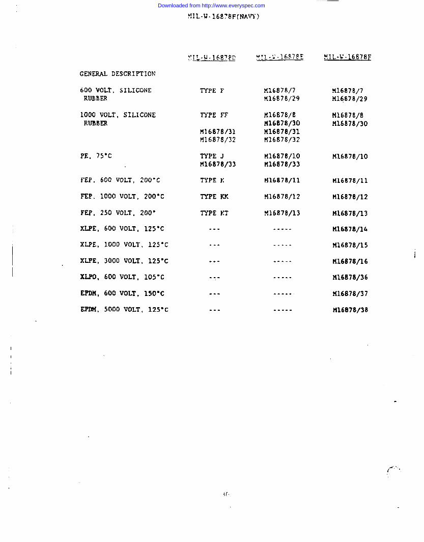
!?IL-N-15876D MIL -W-16878~ MlL-U-16878F
GENERAL DESCR1PTION .
600 VOLT, 105*C PVC
1000 VOLT, 105’C PVC
3000 VOLT, 105-C PVC
600 VOLT, 200-C/260*CPm
1000 VOLT, 200*C/260-CPTFE
250 VOLT, 200”C/260*CPTFE
TYPE B M16878/1 M16878/1M16878/17 K16878/17
TYPE CH16878/18
TYPE DH16878/19
TYPE E
M16878/25!516878/26
TYPE EE
ri16878/27M16878/28!416878/34
M16878/35
TYPE ET
M16878/23M16878/24
?i16t378/2t416878/18
M16878/3K16878/19
H16878/4tt16878/21H16878/25!416878/26
M16878/5!06878/22tf16878/27!416878/28U16878/34H16878/35
X1687816U16878/20CS16878/23M16878/24
H16878/2
H16878/3
M16878/4U16878/21
M16878/5H16878/22
.K16878/6!416878/20
! ,,
Downloaded from http://www.everyspec.com
.——
P!l L.u-16878F(NAm-)
GENERAL DESCRIPTION
600 VOLT, SILICONERUBBER
TYPE F K16878/7K16878/29
316878/7M16878/29
1000 VOLT, SILICONERUBBER
H16878/8H16878/30!f16878/31M16876/32
TYPE FF
!116878131M16878/32
TYPE JM16878/33
TYPE X
TYPE I(X
TYPE XT
H16878/8!i16878/30
PE, 75-C K16878/10U16878/33
M16878/10
FEP, 600 VOLT, 200”C
PEP. 1000 VOLT, 200°C
FEP, 250 VOLT, 200D
XLPE, 600 VOLT, 125°C
XLPE, 1000 VOLT, 125*C
XLPE, 3000 VOLT, 125=C
XLPO, 600 VOLT, 105*C
EPDH, 600 VOLT, 150”C
EPDH, 5000 VOLT, 125-C
M16878/11 H1687B/11
M16878/12
M16878/13
M16878/14
11116878/15
K16878/16
F$16878/36
H16878/37
M16878/38
H16878/12
M16878/13
--- -.-.-
.-. --..-1
--- -----
--- -.-.-
-.. -----
--- -----
I
___{ . .
“{f
Downloaded from http://www.everyspec.com
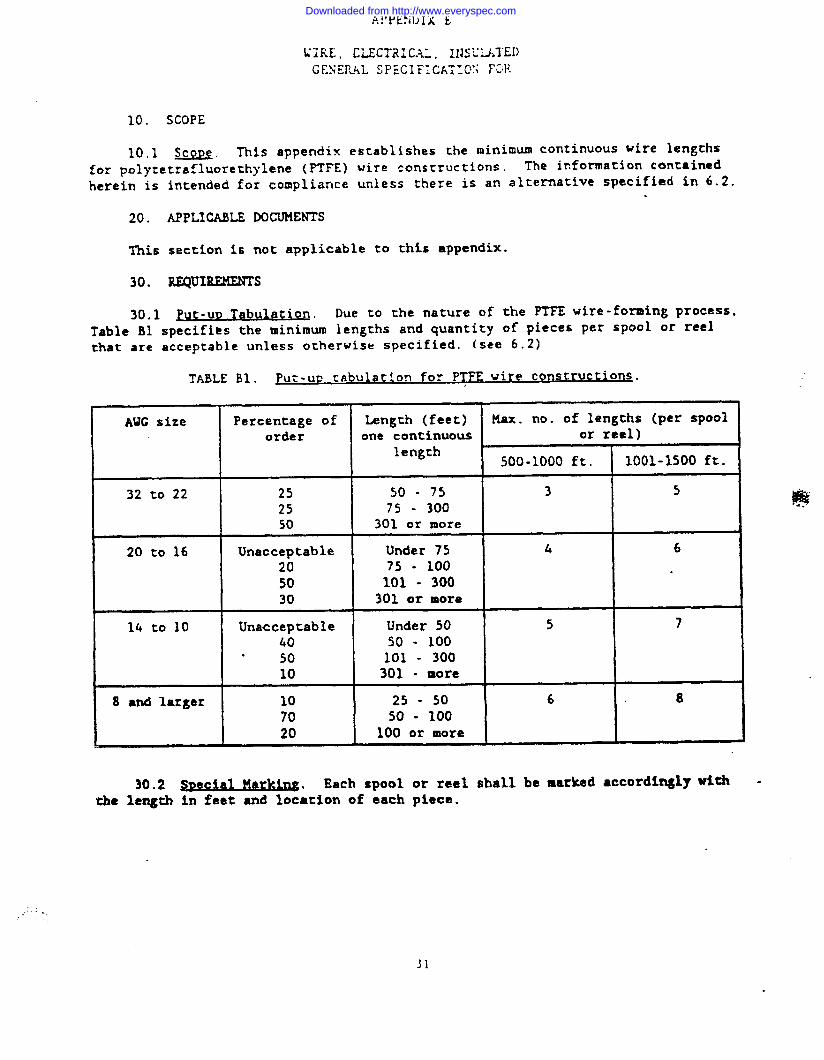
10. SCOPE
10.1 scoDe. This appendix establishes the minimum continuous wire lengths
for ~olvtetrafluorethylene (=FE) wire constructions. The information contained
herek is
20.
Thi6
30.
30.1
intended for compliance unless there is an alternative specified in 6.2.
APPLICABLE DOCUMENTS
section is not applicable to this appendix.
REQuxREMEIWs
W UQ Tabu~at. ion. Due to the nature of the PTFE wire-forming process,Table B1 suecifips the minimum lengths and quantity of pieces per spool or reelthat ●re acceptable unless otherwise specified. ~see 6.2)
TABLE B1. Pur-up ciibulacion for PTFP.wire constructims .
AWG size Percentage of Length (feet) Max. no. of lengths (per spoolor&r one continuous or reel)
length500-1000 ft. 1001-1500 ft.
32 to 22 25 50 - 75 3 525 75 - 30050 301 or more
20 to 16 Unacceptable Under 75 4 6
20 75 - 10050 101 - 30030 301 or mora
14 to 10 Unacceptable Under 50 5 740 50 - 100
. 50 101 - 30010 301 - more
8 and larger 10 25 - 50 6 870 50 - 10020 100 or more
30.2 ~ Pla~. Each spool or reel shall be marked accordingly withthe length in feet and location of each piece.
.,’---,,
Downloaded from http://www.everyspec.com
Downloaded from http://www.everyspec.com
STANDARDIumON DOCUMENT IMPROVEMEW” PROPOSAL
INSTRUCTIONS
1. The preparing activity mu$t tomplete blocks 1, 2, 3, and 8.In block 1, both the document number and revision
lettershould be given.
2. The submitter of this form must complete blocks 4,5,6, and 7. t
3. The preparingactivity must provide a reply within 30days from receipt of the form.
NOTE: This form may not be wed to request copies of documenti,nor to request wti-, or clarification of
requirement on current contracts. Comments submitted on this form do not constitute or imply ●uthofiutiw to i
waive any portion of the referenced document(s) or to ●mend contractual requirement.
.
X 00WMEMT OATt (~-)11 SEPTEMBER 1992
WIRE , ELECTRICAL, INSULATED. GENERAL SPE. NATURE W --GE (titifY PwWWh -br •~ ~~* ~ ~-r
~w’bk. A~~ •~~ -~ ● ~~
_.. .- . . ..—.-— rv● . NAME b. TaEP’Mq4E(- Ama -J
TECHNICAL POUT OF CONTRACT{1)Commerf-1 (2) Mnc7vcm
MR. C. Y. LU., SEA 05E23 (703) 602-3124 8-332-3124 .:. :““
L__
t. AOORESS@CludPz code~: (!5Q42, NAVU SEA SYSTDfS
F YOU DO NOT RECEIVE A REMY WKNIN 45 DAYS. CONYACT:
COMMAM)ER, ATT
COMMAND , 2531 NATIONAL CENTER 3
oetwne OualitYWI StandardizatmOtkeS203 MSbUKj P[ke. $Wte ~403,FBIIsChub, VA 22041.Mti
WASHIN~ON , I’).C . 20362-5160~der)twe(703)7%-z3~ AuToWN 28%23@
-,---cM3 Form 1426, OU 89
Previous ditlon.f @r@ ObSO&@
Downloaded from http://www.everyspec.com